

Page 1

INSTRUCTION MANUAL
FOR
LOSS OF EXCITATION RELAY
BE1-40Q
Publication: 9171500990
Revision: N 12/12
Page 2

Page 3

INTRODUCTION
This instruction manual provides information about the operation and installation of the BE1-40Q Loss of
Excitation Relay. To accomplish this, the following information is provided:
General Information and Specifications
Controls and Indicators
Functional Description
Installation
Testing
WARNING!
To avoid personal injury or equipment damage, only qualified personnel should
perform the procedures in this manual.
NOTE
Be sure that the relay is hard-wired to earth ground with no smaller than 12 AWG
copper wire attached to the ground terminal on the rear of the unit case. When
the relay is configured in a system with other devices, it is recommended to use a
separate lead to the ground bus from each unit.
9171500990 Rev N BE1-40Q Introduction i
Page 4

First Printing: November 1986
Printed in USA
© 2012 Basler Electric, Highland Illinois 62249 USA
All Rights Reserved
December 2012
CONFIDENTIAL INFORMATION
of Basler Electric, Highland Illinois, USA. It is loaned for confidential use, subject
to return on request, and with the mutual understanding that it will not be used in
any manner detrimental to the interest of Basler Electric.
It is not the intention of this manual to cover all details and variations in equipment, nor does this manual
provide data for every possible contingency regarding installation or operation. The availability and design
of all features and options are subject to modification without notice. Should further information be
required, contact Basler Electric.
BASLER ELECTRIC
12570 STATE ROUTE 143
HIGHLAND IL 62249 USA
http://www.basler.com, info@basler.com
PHONE +1 618.654.2341 FAX +1 618.654.2351
ii BE1-40Q Introduction 9171500990 Rev N
Page 5

REVISION HISTORY
The following information provides a historical summary of the changes made to the BE1-40Q instruction
manual (9171500990). Revisions are listed in reverse chronological order.
Manual
Revision and Date
N, 12/12
M, 01/11
L, 09/07
K, 02/01
J, 10/98
H, 03/95
G, 01/94
Standardized case and cover drawings in Section 4.
Updated equations in Note 1 under Figure 5-2.
Improved timing specs under Operational Test, Timing Verification in
Section 5.
Added manual part number and revision to footers.
Updated Output Contact ratings in Section 1.
Updated Power Supply Burden data in Section 1.
Updated front panel illustrations to show laser graphics.
Updated Target Indicator description in Section 3.
Added GOST-R to Section 1, General Information.
Moved content of Section 7, Manual Change Information to Manual
Introduction.
Moved content of Section 6, Maintenance to Section 4, Installation.
Updated S1 case drawings in Section 4 to the most recent drawings.
Corrected Voltage Sensing in Specifications from “Each have a
burden that is less than 0.1 ohm over the” to “Each have a burden
that is less than 1 VA over the”.
Deleted 500 Vdc from Resistive Output Circuits.
Deleted all references to Service Manual.
Updated Style Number Identification Chart by changing Power Supply
Type T from “230 Vac” to “240 Vac”.
Added new power supply information to Specifications and Section 3
starting with “Basler Electric enhanced the power supply design…”
Changed the format of the manual.
Changed Section 1, General Information, Specifications, Output
Circuits and Isolation.
Added phase rotation sensitivity information to Section 3, Functional
Description.
Changed Section 4, Installation, Dielectric Test, to reflect specification
changes.
Corrected Figure 4-1 and changed Figure 5-2, note 2.
Corrected typographical error in Table 5-4, Reactive Power (Vars),
+120.
Corrected typographical error in Section 6, Maintenance, General.
Deleted references to mho characteristic.
Corrected Figure 4-3 (Sensing Input Test Setup), current sensing
input terminals 8 and 9 were reversed on earlier versions;
renumbered equations; updated format; and added new internal
connection diagrams Figures 4-3 through 4-5, added new mounting
diagrams Figures 4-6 through 4-14.
Added new Section 5, Setting and Testing, moved appropriate data
from Section 4 into Section 5, and changed Section 5 and 6 to
Section 6 and 7.
Change
9171500990 Rev N BE1-40Q Introduction iii
Page 6

Manual
Revision and Date
F, 01/91
E, 09/90
D, 08/89
C, 06/89
B, 11/88
A, 11/88
—, 01/86
Change
Pages 1-3, 1-5 (Style Chart), 1-7 2-1 (Item H), 4-4 (step 3), 4-7 (Step
3): Time delay range is 0.1 to 9.90 seconds, adjustable in increments
of 0.1 seconds. This was previously unclear or (in some cases)
erroneous.
Page 1-8: RFI specification added.
Pages 1-6, 5-1: minor editing.
Legend of Figure 3-2 corrected.
Page 3-1 (under “Phase Shift”): 68 was 52.
Equations 4.1 through 4.4 put into standard form by removing
negative sign from the angle theta.
Figure 3-2 corrected.
Equations on page 4-8 restated for clarification.
Arithmetical errors corrected in the example given on page 4-8.
Table 4-2 corrected.
Figure 4-3 was reformatted.
Figure 4-7 revised to clarify installation.
Minor corrections and editing.
Figure 3-3 added.
Editing changes made to clarify specifications.
Two articles added to Section 4, entitled, “Setting the Pickup” (page
4-5) and, “Relay Characteristic Verification” page 4-7.
Initial release
iv BE1-40Q Introduction 9171500990 Rev N
Page 7

CONTENTS
SECTION 1 • GENERAL INFORMATION ................................................................................................ 1-1
PURPOSE ........................................................................................................................................... 1-1
APPLICATION .................................................................................................................................... 1-1
Capability Curves ......................................................................................................................... 1-1
BE1-40Q Operating Characteristics ............................................................................................. 1-1
Time Delay .................................................................................................................................... 1-1
MODEL AND STYLE NUMBER .......................................................................................................... 1-3
Style Number Example ................................................................................................................. 1-3
SPECIFICATIONS .............................................................................................................................. 1-4
Current Sensing ............................................................................................................................ 1-4
Current Sensing Burden ............................................................................................................... 1-4
Voltage Sensing ........................................................................................................................... 1-4
Pickup Range ............................................................................................................................... 1-4
Pickup Accuracy ........................................................................................................................... 1-4
Dropout ......................................................................................................................................... 1-4
Time Delay Range ........................................................................................................................ 1-4
Timing Accuracy ........................................................................................................................... 1-4
Output Contacts ............................................................................................................................ 1-5
Power Supply................................................................................................................................ 1-5
Target Indicators ........................................................................................................................... 1-6
Type Tests .................................................................................................................................... 1-6
Physical ........................................................................................................................................ 1-6
Agency Recognition/Certification.................................................................................................. 1-6
SECTION 2 • CONTROLS AND INDICATORS ....................................................................................... 2-1
INTRODUCTION ................................................................................................................................. 2-1
SECTION 3 • FUNCTIONAL DESCRIPTION ........................................................................................... 3-1
INTRODUCTION ................................................................................................................................. 3-1
VOLTAGE SENSING .......................................................................................................................... 3-1
PHASE SHIFT ..................................................................................................................................... 3-1
CURRENT SENSING ......................................................................................................................... 3-2
HI/LOW RANGE SWITCH .................................................................................................................. 3-2
TAP SWITCH ...................................................................................................................................... 3-3
TRANSDUCER ................................................................................................................................... 3-3
COMPARATOR .................................................................................................................................. 3-3
TIMING ................................................................................................................................................ 3-3
OUTPUTS ........................................................................................................................................... 3-3
PUSH-TO-ENERGIZE OUTPUT PUSHBUTTON .............................................................................. 3-3
POWER SUPPLY STATUS OUTPUT ................................................................................................ 3-3
POWER SUPPLY ............................................................................................................................... 3-3
TARGET INDICATORS ...................................................................................................................... 3-4
Internally Operated Targets .......................................................................................................... 3-4
Current Operated Targets ............................................................................................................ 3-4
SECTION 4 • INSTALLATION ................................................................................................................. 4-1
INTRODUCTION ................................................................................................................................. 4-1
RELAY OPERATING GUIDELINES AND PRECAUTIONS ............................................................... 4-1
MOUNTING ......................................................................................................................................... 4-1
CONNECTIONS ................................................................................................................................ 4-14
MAINTENANCE ................................................................................................................................ 4-17
STORAGE ......................................................................................................................................... 4-17
9171500990 Rev N BE1-40Q Introduction v
Page 8

SECTION 5 • TESTING ............................................................................................................................ 5-1
SETTING ............................................................................................................................................. 5-1
Per Unit Conversion Example ...................................................................................................... 5-1
OPERATIONAL TEST ........................................................................................................................ 5-2
Introduction ................................................................................................................................... 5-2
Pickup Verification ........................................................................................................................ 5-2
Timing Verification ........................................................................................................................ 5-4
Relay Characteristics Verification ................................................................................................. 5-4
vi BE1-40Q Introduction 9171500990 Rev N
Page 9

SECTION 1 • GENERAL INFORMATION
PURPOSE
Loss of excitation protection is applied on nearly all synchronous generators. Reduced or complete loss of
excitation can cause loss of synchronism, instability and, possibly, damage to the generator from
overheating. Many modern excitation systems include minimum-excitation limiters to prevent
underexcitation; however, loss of excitation protective relays are still applied as backup to these
automatic controls. BE1-40Q Loss of Excitation Relays provide this protection by monitoring the field
excitation (measuring t he magnitude and direct ion of var flow) and tripp ing the generator befor e serious
damage to the generator can occur.
Synchronous generators in parallel are normally operated in the overexcited (lagging) region, which
allows generation o f reactive pow er (vars). Altho ugh the field ex citation may be safely adjusted to cause
the generator to abs orb vars (leading), this is usu ally avoided because stability is unreliable under this
condition.
When field excitation is not sufficient to m aintain the ter minal voltage of a n interconnect ed generator, the
system will attempt to supply reactive power to excite the generator. If the system cannot supply the
required vars, the weakened field may allow the rotor to slip poles during disturbances such as load
changes or faults, causing loss of synchronism.
When the system can supply the necessary vars, the generator will act as an induction generator,
drawing excitation fro m the system. The machine vo ltage will remain above the s etting of undervoltage
relays, but the current induced by the rotor slip will flow in the damper (amortisseur) windings. The
excessive heating caused by the current flow reduces machine life exponentially.
Under either condition, BE1-40Q Relays will detect the increased vars at the generator terminals as a loss
of excitation and trips the generator to prevent loss of synchronism or excessive heating within the
generator.
APPLICATION
Capability Curves
Generator manufacturer s supply c apability c urves that s pecify the opera ting limits of a particular mac hine
(similar to those shown in Figure 1-1). The curves ar e derived from the h eating charac teristics that oc cur
on the stator end iron, th e s tator windi ng, and t he roto r wind ing. Plott ed on the co mplex power pla ne, real
power P (kW) is on the horizontal axis and reactive power Q (var) is on the vertical axis.
An additional limit is often included on these curves, as shown in Figure 1-2. Here, the steady state
stability limit further defi nes the safe operating limit of the gen erator. If the stability limit is exceeded, an
out-of-step condition can occur due to loss of synchronism.
BE1-40Q Operating Characteristics
BE1-40Q relay charac teristics c losely follow the gen erator capabi lity curves. The r esponse character istic
is represented by a line eight degrees from horiz ontal, placed above the most restrictive limit of nor mal
operation. As shown in Figure 1-3, the attendant inter c ept of the l ine o n the Q axi s (at –0.4 per unit v ar s in
this example) is used to es tablish the pickup of the relay. A front panel rot ary switch is used to set the
TAP setting. Refer to Section 5, Setting and Testing , for specific informat ion on determining the pickup
setting.
Time Delay
A time delay is included in BE1-40Q Relays to prevent misoperation for transient conditions such as
power swings due to s ynchronizing or externa l fault clearing. A definite time delay of 0.1 to 9.9 seconds
can be set on the fro nt panel thumbwheels in increments of 0.1 s econd. Setting both thumbw heels to 0
causes an instantaneous trip signal t o be sent when t he TAP setting is ex ceeded. Refer to Section 5 for
specific setting information.
9171500990 Rev N BE1-40Q General Information 1-1
Page 10
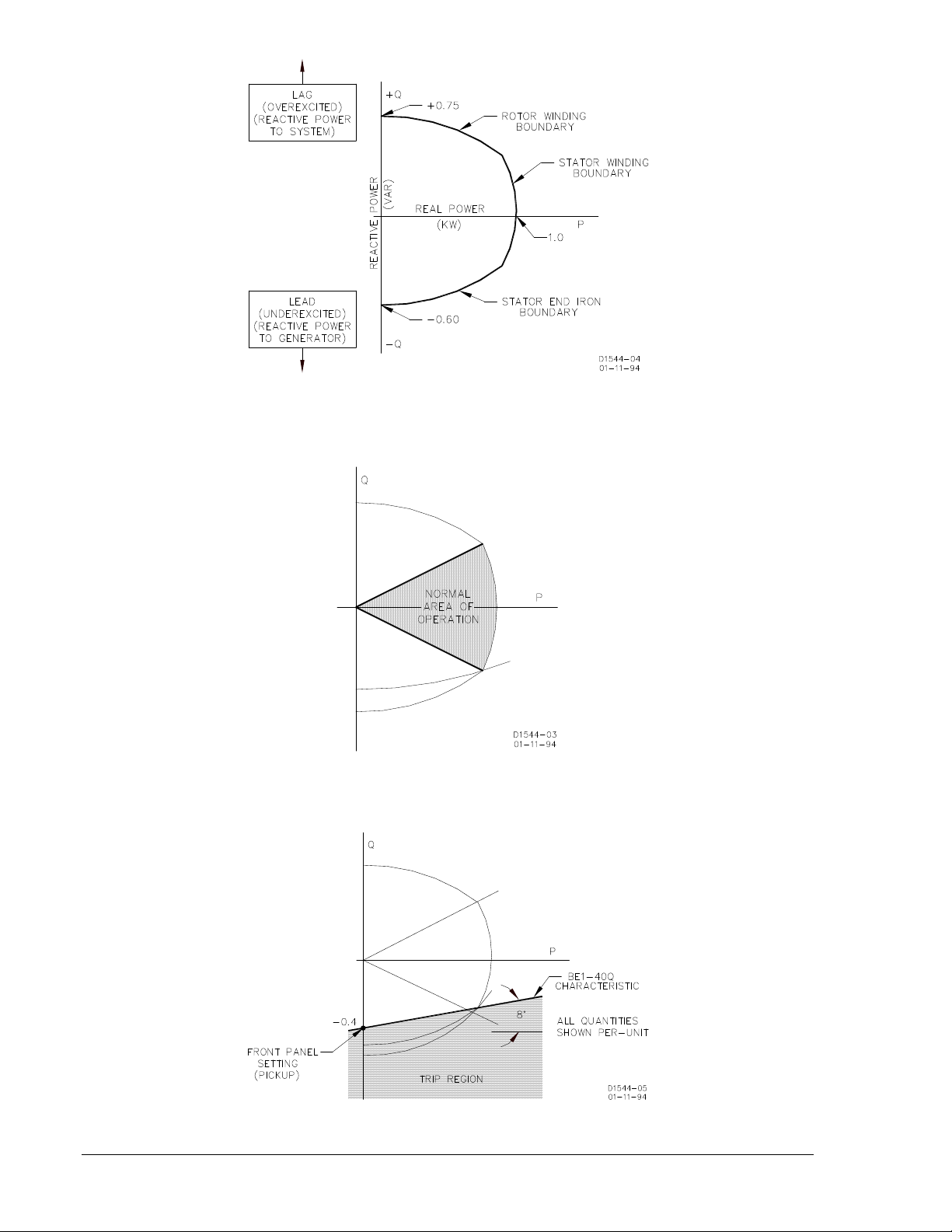
Figure 1-1. Typical Generator Capability Curve
Figure 1-2. Normal Operation with Steady State Stability Limit
Figure 1-3. An example of BE1-40Q Relay Operating Characteristics
1-2 BE1-40Q General Information 9171500990 Rev N
Page 11
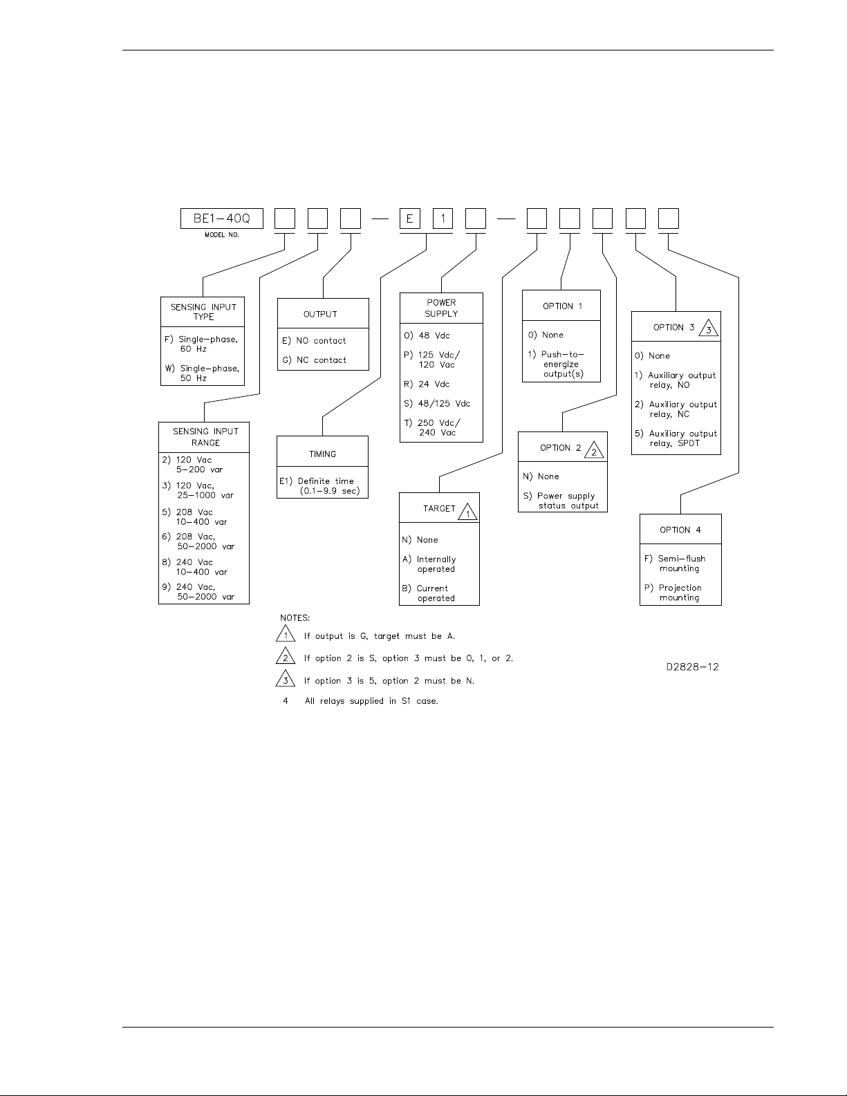
MODEL AND STYLE NUMBER
BE1-40Q electrical charact eristics and operational features are defined by a combination of lett ers and
numbers that make up the style number. Model number BE1-40Q designates the relay as a Basler
Electric Loss of Excitation Relay. The model number, together with the style number, describes the
options included in a sp ecif ic device and app ears on the front panel, draw -out c radle, an d ins ide the c ase
assembly.
The style number identification chart for the BE1-40Q relay is illustr at ed in Figure 1-4.
Figure 1-4. BE1-40Q Style Identification Chart
Style Number Example If a BE1-40Q relay has a style number of F3E–E1O–B1S2F, the relay has the following features:
F -------- 60 Hz single-phase current sensing
3 -------- 120 Vac, 25-1000 var
E -------- One output relay with normally open contacts
E1 ------ Definite timing
O ------- Operating power derived from 48 Vdc
B -------- One current operated target
1 -------- Push-to-energize output
S -------- Power supply status output
2 -------- One auxiliary output relay with normally closed contacts
F -------- Semi-flush mounting case
9171500990 Rev N BE1-40Q General Information 1-3
Page 12

SPECIFICATIONS
BE1-40Q electrical and physical specifications are listed in the following paragraphs.
Current Sensing
Unit is designed to operate from the secondar y of a st andard cur rent trans former r ated at 5 A, 50 and 60
Hz (based on configurat ion). Internal cur rent sensing t ransformers are r ated at 10 A continu ous, 15 A for
1 minute, and 200 A for 1 second.
Current Sensing Burden
Maximum sensing burden is less than 0.1 ohm at pickup over the frequency range of 45 to 65 Hz.
Voltage Sensing
Three line-to-line volt age sensing inputs are available: 120 , 208, and 240 Vac (nominal). Each have a
burden that is less than 1 VA over the frequency range of 45 to 65 Hz.
Pickup Range
Refer to Table 1-1.
Table 1-1. Pickup Ranges
Sensing Input
Range
2
120 Vac
3
120 Vac
5
208 Vac
6
208 Vac
8
240 Vac
9
240 Vac
Pickup Accuracy
±2% of the front panel setting or ±0.1 var, whichever is greater for a power factor angle of –90°.
Tap A B C D E F G H J K
HI 20 40 60 80 100 120 140 160 180 200
LOW 5.0 10 15 20 25 30 35 40 45 50
HI 100 200 300 400 500 600 700 800 900 1000
LOW 25 50 75 100 125 150 175 200 225 250
HI 40 80 120 160 200 240 280 320 360 400
LOW 10 20 30 40 50 60 70 80 90 100
HI 200 400 600 800 1000 1200 1400 1600 1800 2000
LOW 50 100 150 200 250 300 350 400 450 500
HI 40 80 120 160 200 240 280 320 360 400
LOW 10 20 30 40 50 60 70 80 90 100
HI 200 400 600 800 1000 1200 1400 1600 1800 2000
LOW 50 100 150 200 250 300 350 400 450 500
Dropout
Not less than 95% of actual pickup.
Time Delay Range
Definite time delay is adjustable by two front panel thumbwheels over a range of 01 to 99 (0.1 to 9.9
seconds) in increments of 0.1 seconds. A setting of 00 enables instantaneous operation.
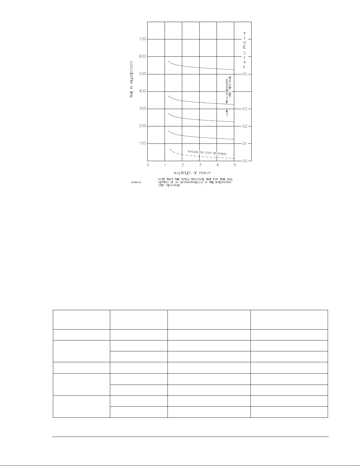
Timing Accuracy
Shown in Figure 1-5. Note that eac h curve is slightly offset by a factor that repr esents integration time.
Repeatability is within ±5% or 25 milliseconds, whichever is greater.
1-4 BE1-40Q General Information 9171500990 Rev N
Page 13
Input Voltage
O (midrange)
48 Vdc
24 to 150 Vdc
1.9 W
125 Vdc
24 to 150 Vdc
2.2 W
120 Vac
90 to 132 Vac
18.4 VA
R (low range)
24 Vdc
12 to 32 Vdc ∗
1.9 W
48 Vdc
24 to 150 Vdc
1.9 W
250 Vdc
68 to 280 Vdc
2.3 W
240 Vac
90 to 270 Vac
32.1 VA
Figure 1-5. Typical Relay Response Time for Time Dial Settings
Output Contacts
Resistive Ratings
120 Vac: Make, break, and carry 7 Aac continuously
250 Vdc: Make and carry 30 Adc for 0.2 s, carry 7 Adc continuously,
break 0.3 Adc
500 Vdc: Make and carry 15 Adc for 0.2 s, carry 7 Adc continuously,
break 0.3 Adc
Inductive Ratings
120 Vac, 125 Vdc, 250 Vdc: Break 0.3 A (L/R = 0.04)
Power Supply
Power supply types and specifications are listed in Table 1-2.
Table 1-2. Power Supply Ratings
Type
P (midrange)
S (midrange)
T (high range)
∗ Type R power supply initi ally requir es 14 Vdc to begi n operat ing. Onc e operati ng, the i nput v oltage m ay
be reduced to 12 Vdc and operation will continue.
9171500990 Rev N BE1-40Q General Information 1-5
Nominal
125 Vdc 24 to 150 Vdc 2.2 W
Input Voltage Range Burden at Nominal
Page 14

Target Indicator
An electronically latched, manually reset targ et indicator is optionally avai lable to indicate closure of the
trip output contact. Either an internally operated or a current operated target may be specified. An
internally operated target should be selected when a normally closed (NC) output contact is specified.
Current Operated Target
Minimum Rating: 200 mA flowing through the trip circuit
Continuous Rating: 3 A
1 Second Rating: 30 A
2 Minute Rating: 7 A
Type Tests
Shock: Withstands 15 G in each of three mutually perpendicular planes
without structural damage or performance degradation.
Vibration: Withstands 2 G in each of three mutually perpendicular planes,
swept over the range of 10 to 500 Hz for a total of six sweeps, 15
minutes each sweep, without structural damage or degradation of
performance.
Dielectric Strength: Tested in accor dance wit h IEC 255-5 and IEEE C37.90. All circuits to
ground: 2,121 Vdc. Input to Output circuits: 1,500 Vac/2,121 Vdc.
Radio Frequency Interference: Maintains proper operation when tested for interference in
accordance with IEEE C37.90.2-1987, Stand ar d Withs tand
Capability of Relay Systems to Radiated Electromagnetic
Interference from Transceivers.
Surge Withstand Capability: Qualified to IEEE C37.90.1-1989, Standard Surge Withstand
Capability (SWC) Tests for Protective Relays and Relay Systems.
Physical
Temperature
Operating Range: –40 to 70°C (–40 to 158°F)
Storage Range: –65 to 100°C (–85 to 212°F)
Weight: 13.5 lb (6.12 kg)
Case Size: S1 (Refer to Section 4 for case dimensions.)
Agency Recognition/Certification
UL Recognition: UL recognized per Standard 508, File E97033
NOTE: Output contacts are not UL recognized for voltages greater
than 250 volts.
GOST-R Certification: GOST-R certified per the relevant standards of Gosstandart of
Russia.
1-6 BE1-40Q General Information 9171500990 Rev N
Page 15
SECTION 2 • CONTROLS AND INDICATORS
Locator
Description
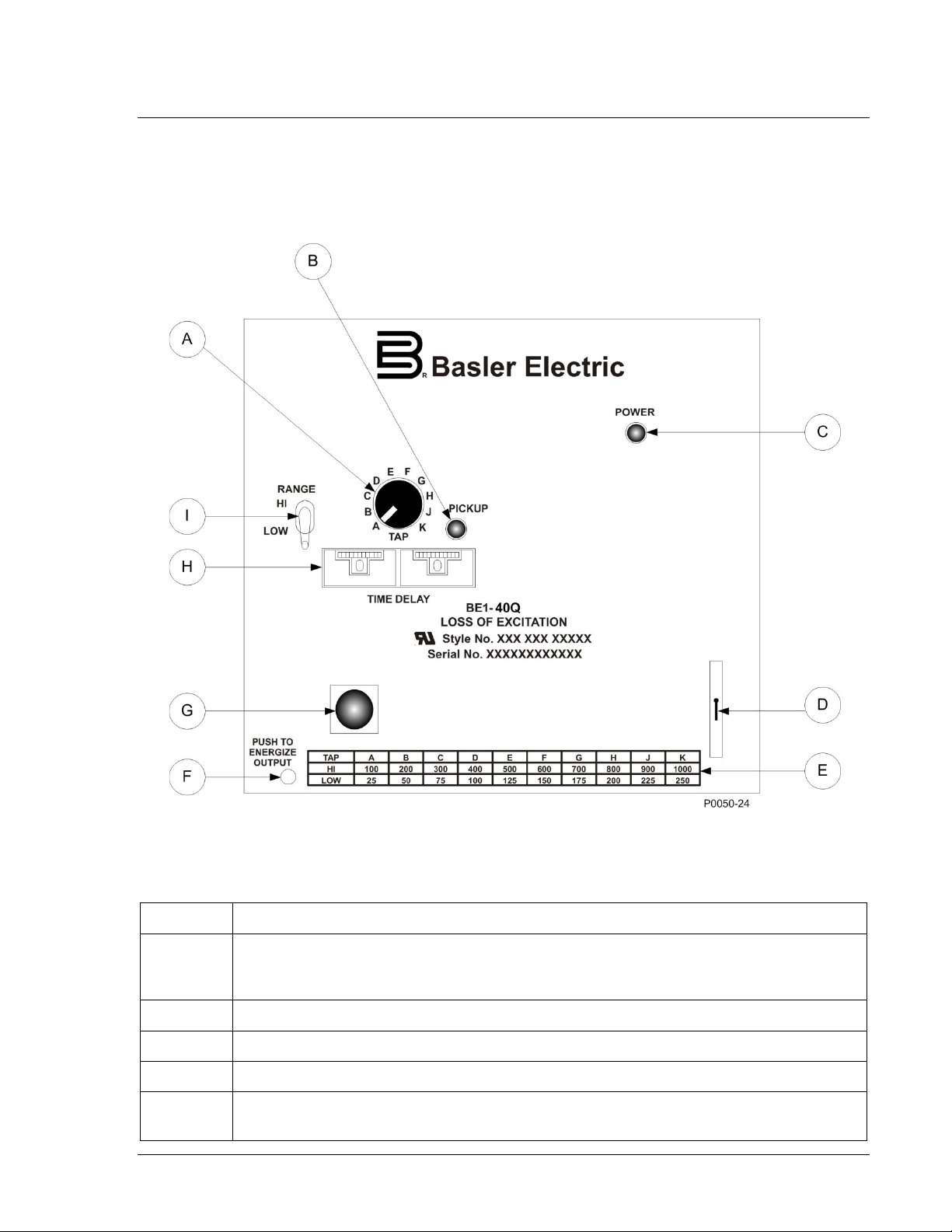
INTRODUCTION
All BE1-40Q cont rols and indicat ors ar e located on th e front pan el. Th e controls and indic ators are show n
in Figure 2-1 and described in Table 2-1. Figure 2-1 illustrates a relay with the maximum number of
controls and indicators . Your relay may not hav e all of the controls and indicators shown and des cribed
here.
Figure 2-1. BE1-40Q Controls and Indicators
Table 2-1. Control and Indicator Descriptions
A
B Pickup Indicator. LED illuminates to indicate that the pickup level has been exceeded.
C Power Indicator. This red LED lights when operating power is applied to the relay.
D Target Reset Switch. This switch is operated to reset the target indicator.
E
9171500990 Rev N BE1-40Q Controls and Indicators 2-1
Tap Switch. A ten-posi tion rotary switch sets the pic kup point when used in con junction
with the Range switch (see Locator I). Pickup levels (in vars) are labeled on the Tap
Range Chart (see Locator E).
Tap Range Chart. Provides an index of re active power leve ls (in vars) that corr espond to
the Tap switch positions.
Page 16

Locator Description
F
G
H
I Range Switch. Two-position switch selects the reactive power range (HI or LOW) desired.
Output Test Pushbutton. This pushbutton allows manual actuation of the output relay.
Output relay actuation is achieved by inserting a nonconductive rod through the front
panel access hole.
Target Indicator. The electronically latched red target indicator illuminates when the
corresponding output re lay ener g izes . T o ensur e pr op e r oper ati on of th e c ur rent -operated
target, the current flow ing through the trip circuit must be 200 mA or higher. The target
indicator is reset by operating the target reset switch (locator D).
Time Delay Selectors. Two thumbwheel switches select the trip time delay. The left
thumbwheel represents seconds; the right thumbwheel represents tenths of a second.
2-2 BE1-40Q Controls and Indicators 9171500990 Rev N
Page 17

SECTION 3 • FUNCTIONAL DESCRIPTION
INTRODUCTION
BE1-40Q Loss of Excitation relays are static devices that respond to the relation of voltage to current
magnitudes of the monitore d circuit. As such, they are sensitive to phas e rotation. All conn ections shown
in this manual assume ABC rotat ion. BE1-40Q relay functions are illustrated in Figure 3-1 and described
in the following paragraphs.
Figure 3-1. Function Block Diagram
VOLTAGE SENSING
The monitored voltag e input is derived from a system voltage tra nsformer c onnected phase-to-phase. An
internal voltage trans former ( PT) provid es isolation and reduc es the nom inal va lue of the vo ltage sens ing
input (i.e., 120, 208, or 240 Vac) to internal circuitry requirements.
PHASE SHIFT
Since the voltage input, VAB, leads the sensed input current , IB, by an angle of 150° for a unity power f actor
condition, the voltage phasor is interna lly shifted 68° in a lagg ing direction (del ayed) to achieve the re lay
response characteristics. The resultant I
power factor angle (Ө) is equal to –90° as shown in Figure 3-2.
leads the polarizing voltage V
TRIP
by 8° (when the system
POL
9171500990 Rev N BE1-40Q Functional Description 3-1
Page 18

( )
( )
°
−°
8cos
8sin
3
θ
BAB
IV
( )
−°
°
=
θ
8sin
8cos3
Setting Pickup Panel
Front
AB
B
V
I
The response of the relay is:
Figure 3-2. Phase Shift Example
Front Panel Pickup Setting =
Or
Where:
V
I
Ө = system power factor angle = (voltage angle) – (current angle)
= phase A to phase B voltage magnitude
AB
= phase B current magnitude
B
CURRENT SENSING
The monitored current is derived from the secondary of a system current trans former rated nominal fiv e
amperes. An internal c urrent transformer (CT) provid es isolation and scaling for pr oper relay operation.
The front panel HI/LO W RANG E switch uses th e tapped sec ondary of the internal CT for ra nge selec tion
to increase pickup stability.
Note that when the connection plugs (paddles) are removed, the CT inputs are shorted.
HI/LOW RANGE SWITCH
The front panel HI/LO W RANGE sw itch selects w hich secondar y winding of t he interna l CT is connec ted
to the TAP switch and thus the measure ment circuitry. The pos ition of this switch may be c hanged while
3-2 BE1-40Q Functional Description 9171500990 Rev N
Page 19

sensing current is pr esent. The effect of this sw itch, in conjunction w ith the TAP switch, is shown in the
Specifications, Table 1-1, and on the front panel tap range chart.
TAP SWITCH
The front panel TAP s witch selec ts th e pick up sett ing (in si ngle-phase vars), depe nding o n the p ositi on of
the HI/LOW RANGE swi tch, as shown in Table 1-1. The T AP switch selects the resistiv e burden value
that is placed across the output of the internal sensing input CT. The resistive burden establishes the
scaling of the internal signal that represents the input current value.
TRANSDUCER
The transducer consists of a multiplier and integrator. The multiplier and associated control circuits
produce an output th at is repres entative of the pro duct of th e scaled cur rent input and the sc aled, phas eshifted voltage input signa l. The output waveform of the multiplier is an instantaneous value; therefore,
the output is integrated to develop a signal that represents the average var value. The integrator
response time is a function of the pickup multiple, as shown in Section 1, Specifications.
COMPARATOR
The signal representing the single-phase var value is compared with the pickup reference. When the
reference value is exceeded, the PICKUP LED indicator is illuminated and timing is initiated.
TIMING
A definite time delay is initiated wh en the monitored var level ex ceeds the pickup r eference. A calibrated
frequency generating circuit, in conjunction with counter circuits and the front panel TIME DELAY
thumbwheel switches, establishes the definite time delay interval.
Time delay is adjustable from 0.1 to 9.9 seconds in 0.1-second intervals. A setting of 00 enables
instantaneous (no intentional time delay) operation. Timing is instantaneously reset if the var level
reduces to less than the pickup setting.
For a complete description of timing accuracy, refer to Specifications in Section 1.
OUTPUTS
Defined by the styl e number, the out put relay may ha ve either a norma lly open (NO) or nor mally closed
(NC) configuration. T he nor mally open output c ontac t opti on is r equire d wh en a current oper ated t arget is
desired.
In addition, an auxiliary out put cont act may b e prov ide d which is specif ied by style num ber as NO , NC, or
SPDT. If an auxiliary contact is provided, then the power supply status output is not available.
PUSH-TO-ENERGIZE OUTPUT PUSHBUTTON
A small pushbutton switch may be provided as an option to allow testing the primary output contact and (if
present) the auxiliary output contac t. To prevent ac cidental oper ation, the pushb utton is rec essed behind
the front panel and is depres sed by inserting a thin, non-conducting rod t hrough an access hole in the
front panel.
POWER SUPPLY STATUS OUTPUT
The power supply status rel ay has a set of normally closed c ontac ts an d e ner gizes when operating pow er
is applied to the BE1-40Q. If relay operating power is lost or either side of the power supply output
(+12 Vdc or –12 Vdc) fails, the power supply status relay de-energizes and opens the power supply
status output contacts.
POWER SUPPLY
Operating power for the r el ay circ uitry is supplie d by a wide rang e, elec trica lly iso lated, low-b urden pow er
supply. Power supply operating power is not polarity sensitive. The front panel power LED and power
supply status output indicate when the power supply is operating. Power supply specifications are listed in
Table 1-1.
9171500990 Rev N BE1-40Q Functional Description 3-3
Page 20

TARGET INDICATOR
A target indicator is an optional compone nt selected when a relay is ordered. T he electronically latched
and reset target consis ts of a red LED indicator locate d on the relay front panel. A la tched target is reset
by operating the target reset switch on the front panel. If relay operating power is lost, an illuminated
(latched) target is extinguished. Whe n relay operating power is restor ed, the previously latched tar get is
restored to its latched state.
A relay can be equipped with either an internally operated target or current operated target.
Internally Operated Target
The relay trip output is d irectly appl ied to drive th e target in dicator. The indicator is illuminated regardless
of the current level in the trip circuit.
Current Operated Target
A current operated tar get is triggered by closure of t he output contact and the presence of at least 200
milliamperes of current flowing in the trip circuit.
NOTE
Prior to September 2007, BE1-40Q the target indicator consisted of a
magnetically latched, disc indicator. This mechanically latched target indicator
has been replaced by the electronically latched LED target in use today.
3-4 BE1-40Q Functional Description 9171500990 Rev N
Page 21

SECTION 4 • INSTALLATION
INTRODUCTION
BE1-40Q relays are shippe d in sturdy cartons to prevent da mage during transit. Upon rec eipt of a relay,
check the model an d style number a gainst the r equis ition and p acking l ist to s ee that they agree . Inspec t
the relay for shipping dama ge. If ther e is ev idenc e of d amage, f ile a cl aim wi th the carrier, an d notify your
sales representative or Basler Electric.
If the relay will not be installed immed iately, store it in its or iginal shipp ing carton i n a moisture- and dustfree environment. Before placing the relay in service, it is recommended that the test procedures of
Section 5, Setting and Testing be performed.
RELAY OPERATING GUIDE L INES AND PRECAUTIONS
Before installing or operating the relay, not the following guidelines and precautions.
• For proper current operated target operation, a minimum current of 200 milliamperes must flow
through the output trip circuit.
• If a wiring insulation test is required, remove the connection plugs and withdraw the relay from its
case.
CAUTION
When the connection plugs are removed, the relay is disconnected from the
operating circuit and will not provide system protection. Always be sure that
external operating (mo nitored) conditions are stable b efore removing a relay for
inspection, test, or service.
NOTE
Be sure that the re lay is hard-wired to earth gr oun d w it h no s ma ller tha n 12 AWG
copper wire attached to th e ground terminal on the rear of the case. When the
relay is configured i n a system with other devices , it is recommended to use a
separate lead to the ground bus from each device.
MOUNTING
Because the relay is of solid-state design, it does not have to be mounted vertically. Any convenient
mounting angle may be c hosen. Relay outline dimensions and panel drilling diagrams are illustrated in
Figures 4-1 through 4-12.
9171500990 Rev N BE1-40Q Installation 4-1
Page 22

3.03 (77)
6.06 (154)
0.25 (6) diameter, 4 places
C
L
Cut-Out
0.575
(15)
8.63
(219)
0.552
(14)
5.69 (144)
Outer Edge of Cover
0.480
(12)
8.25
(210)
4.13
(105)
0.480
(12)
P0072-12
Figure 4-1. Panel Cutting/D rill ing, Semi-Flush, S1 Case
4-2 BE1-40Q Installation 9171500990 Rev N
Page 23

Figure 4-2. S1 Case Dimensions, Rear View, Double Ended, Semi-Flush Mount
9171500990 Rev N BE1-40Q Installation 4-3
Page 24

.75
(19.1)
(157.2)
6.19
(49.53)
1.95
10-32 SCREWS
(7.9)
.31
10-32 SCREWS
(102.4)
4.03
4.03
(102.4)
(7.9)
.31
MOUNTING PANEL
(55.75)
2.195
P0066-64
Figure 4-3. S1 Case Dimensions, Side View, Double Ended, Semi-Flush Mount
4-4 BE1-40Q Installation 9171500990 Rev N
Page 25

Figure 4-4. S1 Case Dimensions, Rear View, Single Ended, Semi-Flush Mount
9171500990 Rev N BE1-40Q Installation 4-5
Page 26

.75
(19.1)
(157.2)
6.19
(49.53)
1.95
10-32 SCREWS
MOUNTING PANEL
(55.75)
2.195
P0066-69
8.06
(204.72)
(7.9)
.31
Figure 4-5. S1 Case Dimensions, Side View, Single Ended, Semi-Flush Mount
4-6 BE1-40Q Installation 9171500990 Rev N
Page 27

Figure 4-6. Panel Cutting/D rill ing, Doubl e End ed, Proj e c tion Mou nt, S1 Cas e
9171500990 Rev N BE1-40Q Installation 4-7
Page 28

Figure 4-7. S1 Case Dimensions, Rear View, Double Ended, Projection Mount
4-8 BE1-40Q Installation 9171500990 Rev N
Page 29

.75
(19.1)
(157.2)
6.19
(49.53)
1.95
10-32 SCREWS
(7.9)
.31
10-32 SCREWS
(102.4)
4.03
4.03
(102.4)
(7.9)
.31
(55.75)
2.195
P0066-67
TERMINAL EXTENSION (TYP.)
FOR DETAILED INSTRUCTIONS,
SEE THE TERMINAL PROJECTION
MOUNTING KIT SUPPLIED.
.25
(6.4)
5/16-18 STUD
2 PLACES
MOUNTING PANEL
Figure 4-8. S1 Case Dimensions, Side View, Double Ended, Projec t ion Mou nt
9171500990 Rev N BE1-40Q Installation 4-9
Page 30

Figure 4-9. Panel Cutting/Drilling, Single Ended, Projection Mount, S1 Case
4-10 BE1-40Q Installation 9171500990 Rev N
Page 31

Figure 4-10. S1 Case Dimensions, Rear View, Single Ended, Projec tion Mount
9171500990 Rev N BE1-40Q Installation 4-11
Page 32

(157.2)
6.19
(49.53)
1.95
10-32 SCREWS
MOUNTING PANEL
(55.75)
2.195
P0066-71
TERMINAL EXTENSION (TYP.)
FOR DETAILED INSTRUCTIONS,
SEE THE TERMINAL PROJECTION
MOUNTING KIT SUPPLIED.
.25
(6.4)
5/16-18 STUD
2 PLACES
MOUNTING PANEL
8.06
(204.72)
(7.9)
.31
.75
(19.1)
Figure 4-11. S1 Case Dimensions , Side Vi ew, Sin gl e Ended , Projec t ion Mou nt
4-12 BE1-40Q Installation 9171500990 Rev N
Page 33

P
0066-
68
Figure 4-12. S1 Case Cover Dimensions, Front View
9171500990 Rev N BE1-40Q Installation 4-13
Page 34

CONNECTIONS
Be sure to check the model and style number of a relay before connecting and energizing the relay.
Incorrect wiring may r es u lt i n da mag e t o th e r e lay. Except where not ed, connections should be mad e with
wire no smaller than 14 AWG.
Typical sensing input connections are shown in Figure 4-13. Typical output connections are shown in
Figure 4-14. Intern al wiring diagrams are s hown in Figures 4-15 t hrough 4-16. All connections shown in
this manual assume ABC rotation.
Figure 4-13. Sensing Input Conn ectio ns
4-14 BE1-40Q Installation 9171500990 Rev N
Page 35

Figure 4-14. Output Connections
Figure 4-15. Interconnection with Current Operated Targets
9171500990 Rev N BE1-40Q Installation 4-15
Page 36

Figure 4-16. Interconnection with Current Operated Targets and Power Supply Status Output
4-16 BE1-40Q Installation 9171500990 Rev N
Page 37

Figure 4-17. Interconnection with Internally Operated Target and Auxiliary Output Contacts (SPDT)
MAINTENANCE
BE1-40Q r elays requ ire no preventativ e maintenanc e other t han a per iodic opera tional ch eck. If th e relay
fails to function properly, contact Technical Sales Support at Basler Electric to coordinate repairs.
STORAGE
This device cont ains lon g-life a luminu m electr olyt ic ca pacitors . For devices that are not in ser vice (s par es
in storage), the life o f these capacitors can be maximized by energ izing the device for 30 minutes once
per year.
9171500990 Rev N BE1-40Q Installation 4-17
Page 38

This page intentionally left blank .
4-18 BE1-40Q Installation 9171500990 Rev N
Page 39

SECTION 5 • SETTING AND TESTING
LL
V
3
SETTING
Setting the pickup value of BE1-40Q relay s is facilitated by using the capabi lity curves supplied by the
generator manufacturer as shown prev iously in the examp les in Section 1. T he figure for relay o perating
characteristics is repeate d here as Figure 5-1. Not e that the line representing the relay charact eristic is
positioned on the curve 8° from horizontal and just above the poi nt where the steady state s tability limit
arc intersects the capability curve. (The 8° slope applies to all BE1-40Q relays.)
Figure 5-1. Example of BE1-40Q Relay Operating Characteristics
The pickup setting is det ermined by the point wh ere the BE1-40Q charac teristic intersects th e Q axis in
per unit (pu) quantities. Th erefore, for th e example s hown in Figure 5-1, the pickup is –0.4 pu. Th e actual
per unit pickup setting for your relay is determined by your specific application.
Per Unit Conversion Example
The per unit quanti ty is converted to a TAP switch s etting by the procedure described i n the following
example.
Given:
Rated power = 100 MVA
Rated voltage = 12.8 kV
CT ratio = 5000/5
PT ratio = 12800/120
Step 1. Determine the desired primary vars.
Three-phase primary vars = 0.4 x rated power
= 0.4 x 100 MVA
= 40 Mvar
Single-phase primary vars = 13.33 Mvar
Step 2. Determine the desired primary current.
Primary current = (single-phase primary var)
9171500990 Rev N BE1-40Q Setting and Testing 5-1
Page 40

= (13.33 Mvar)
12800
3
Ratio
CT
Current
Primary
5000/5
1804
relay
relay
I
V
×
3
8.1
3
120
×
= 1804 A
Step 3. Specify a BE1-40Q relay having a nominal sensing range of 120 V
12800/120).
Step 4. Determine the desired secondary current.
(for a PT ratio of
LL
Secondary current =
=
= 1.8 A
Step 5. Determine the pickup.
Pickup =
=
= 125
= Low Range, TAP position E (Table 1-1)
OPERATIONAL TEST
Introduction
The following procedures verify proper relay operation and calibration.
Results obtained fr om thes e procedur es may no fall w ithin spec ified tol erances. When evalu ating resu lts,
consider three prominent factors:
• Test equipment accuracy
• Testing method
• External test set components tolerance level
Pickup Verification
Step 1. Connect the test circuit as show n in Figure 5-2. Apply appropriate op erating power, depe nding
on the power supp ly option (refer to th e Style Chart in Sec tion 1), to terminals 3 and 4. Th e
POWER LED should illuminate.
Step 2. For relay styles wit h target indicator s, actuate the target reset switch to insure that th e target is
reset.
Step 3. Make the following front panel adjustments on the BE1-40Q relay:
RANGE switch - LOW position
TAP switch - Position A (minimum)
TIME DELAY switches - 10 (1.0 second)
Step 4. If equipped with a pow er supply status o utput relay (o ption 2-S), verify th at the contact is open
when external power is ap plied. Remove input pow er and verify that the s tatus contacts close.
Re-apply external power.
5-2 BE1-40Q Setting and Testing 9171500990 Rev N
Page 41

relay
relay
I
V
×
3
Figure 5-2. Test Circuit Connections
Step 5. Adjust the voltage source to the nom ina l valu e of the s ens in g input as des ign ated by the s econd
digit of the style number. (Refer to Table 5-1).
Table 5-1. Nominal Sensing Input Vol tag e
Second Digit of Style Number Nominal Ac Voltage
2 or 3 120
5 or 6 208
8 or 9 240
Step 6. Adjust the phase of the current source to produce an output that lags the voltage input by 60°.
Step 7. Slowly increase the mag nit ude of t he c ur ren t s our ce until the PICKUP LE D i ll um i nates . On units
with target indicators, the indicator should illuminate.
NOTE
The equation in Step 8 applies only to Step 8 of the Pickup Verification Test
Procedure. For the pickup response of the BE1-40Q relay, see Section 3,
Functional Description.
Step 8. Note the indicated voltage and current, and calculate the actual pickup value as defined by:
Compare the result with Table 1-1 in Section 1. Reset the target indicator, if present.
9171500990 Rev N BE1-40Q Setting and Testing 5-3
Page 42

Step 9. Repeat Steps 7 and 8 for e ach T AP sett in g, v er ifyin g b oth the HI and LOW range setpoi nts . T he
pickup tolerance should be ±2% of the front panel setting or 0.1 var, whichever is greater.
Timing Verification
Step 1. Connect the test circuit as shown in Figure 5-2.
Step 2. Connect a timer to record the time interval from application of the test current that will be
applied in Step 6, to the c hange of s tate of t h e out put r elay. If a normally open contact has been
selected, a trip will occur when the contact closes; normally closed contacts will open to trip.
Step 3. Make the following front panel adjustments on the BE1-40Q relay:
RANGE switch - LOW position
TAP switch - Position A (minimum)
TIME DELAY switches - 11 (1.1 second)
Step 4. Apply appropriate oper at in g power, dep end ing on th e power s up ply opt io n, to terminals 3 and 4.
The POWER LED should illuminate.
Step 5. Adjust the voltage source to the nom ina l valu e of the s ens in g input as des ign ated by the s econd
digit of the style number.
NOTE
The test current given in Table 5-2 is twice the pickup current.
Step 6. Adjust the current source to pr oduce a 60° lagging current that steps from z er o ma gnit ude to th e
test current value shown in Table 5-2.
Table 5-2. Test Current
Second Digit of
Style Number
2 120 0.072 A 0.144 A
3 120 0.361 A 0.722 A
5 208 0.083 A 0.166 A
6 208 0.416 A 0.832 A
8 240 0.072 A 0.144 A
9 240 0.361 A 0.722 A
Step 7. The actual time delay should be 1.05 to 1.15 seconds.
Step 8. Adjust the TIME DELAY s witches to a settin g of 55 (5.5 seconds) , and repeat Step 6. T he time
delay should be 5.22 to 5.77 seconds.
Step 9. Adjust the TIME DELAY s witches to a settin g of 99 (9.9 seconds ), and repeat S tep 6. The time
delay should be 9.40 to 10.39 seconds.
Relay Characteristics Verification
Preliminary
Step 1. Connect the test circuit shown in Figure 5-2.
Step 2. Adjust the BE1-40Q relay for the desired p ickup va lue as spec ified by th e genera tor applic ation
or the test setup capabilities.
Step 3. Adjust the TIME DELAY switches to a minimum value (e.g., 0.1, 0.2, or 0.3 seconds).
Step 4. Adjust the voltage source to the nom ina l valu e of the s ens in g input as des ign ated by the s econd
digit of the style number, at a leading phase angle of 150°.
Nominal Ac
Voltage
Pickup Current Test Current
5-4 BE1-40Q Setting and Testing 9171500990 Rev N
Page 43

Characteristic Data
( )
θ
cos
3
L
LL
I
V
P =
( )
θ
sin
3
L
LL
I
V
Q =
Step 1. Adjust the current sourc e phase an gle for each of t he values i ndicated in Table 5-3. R ecord the
magnitude of current req uired to receive each pickup indication. T o measure pickup for each
phase angle setting, slow ly increase the current magnitude from zer o or a value less than the
pickup value until the PICKUP LED illuminates and an output contact operation occurs.
NOTE
With the test setup as speci fied , the c ur rent s o ur ce pha s e angl e s etti ng sim ul ates
a leading power factor angle, i.e., Ө < 0.
Table 5-3. Current Magnitudes Requir e d for Pickup
Current Source Phase
Angle Setting (Degrees)
+20
+30
+40
+50
+60
+70
+80
+90
+100
+110
+120
Equivalent System Power
Factor Angle (Ө) In Degrees
–20
–30
–40
–50
–60
–70
–80
–90
–100
–110
–120
Current Magnitude
Required for Pickup (Amps)
Step 2. With the above recor ded data, calculate P (w atts) and Q (vars), as follows , for each recorded
pickup value.
Where:
V
I
= voltage measured in the tes t setup of Figure 5-2
LL
= current measured in the test setup of Figure 5-2
L
Ө = the (–) angle setting of the current source
9171500990 Rev N BE1-40Q Setting and Testing 5-5
Page 44

( ) ( )
°−= 20cos806.3
3
120
P
( ) ( )
°−= 20sin806.3
3
120
Q
[1]
[2]
[3]
[4]
Phase Angle Degrees
Angle Ө
Pickup (Amps)
(Watts)
Power (Vars)
+20
–20
3.806
247.76
–90.18
+30
–30
2.902
174.12
–100.53
+40
–40
2.404
127.60
–107.07
+50
–50
2.107
93.82
–111.81
+60
–60
1.927
66.75
–115.62
+70
–70
1.827
43.28
–118.92
+80
–80
1.788
21.51
–121.98
+90
–90
1.804
0.00
–125.00
+100
–100
1.879
–22.60
–128.18
+110
–110
2.024
–47.95
–131.74
+120
–120
2.267
–78.54
–136.04
NOTE
β,
I
I
and V V ∠=
∝∠=
( )
,β - cos I V ∝×
( )
and ,β - sin I V ∝×
β−∝
If:
Then:
Real power (P) =
Reactive power (Q) =
System power factor angle (Ө) =
Step 3. The results from th e above calculations can n ow be plotted on a graph of the complex power
plane.
Graph Example
Given:
Relay style number is F3E-E1P-B1S1F. (Reference the Style Chart, Figure 1-4.)
Pickup is set to 125. (Reference Table 1-1.)
Test results are obtained as given in Step 1. For this examp le, we are using the data shown in
columns [1] and [2] of Table 5-4.
Step 1. Calculate P and Q for a current phase angle of 20° ( Ө = –20°).
= 247.8 W
= –90.18 vars
Note that the above results for a p hase ang le of –20° have been e ntered in Table 5-4, columns
[3] and [4], first row. Similarly, the values of P and Q can be solved for the other phase angles of
column [1].
Step 2. Finally, the data from Table 5-4 is shown plotted on the comp lex power plane shown in Figure
5-3. A blank graph is provided as Figure 5-4.
Table 5-4. Data for the Hypothetical Graph of Figure 5-3
Current Source
System Phase
Current Magnitude for
Real Power
Reactive
5-6 BE1-40Q Setting and Testing 9171500990 Rev N
Page 45

Figure 5-3. BE1-40Q Relay Characteristics Plotted on Complex Power Plane
Figure 5-4. Blank Graph
9171500990 Rev N BE1-40Q Setting and Testing 5-7
Page 46

This page intentionally left blank .
5-8 BE1-40Q Setting and Testing 9171500990 Rev N
Page 47

Page 48

12570 State Route 143
P.A.E. Les Pins
No. 59 Heshun Road Loufeng District (N)
111 North Bridge Road
Highland IL 62249-1074 USA
Tel: +1 618.654.2341
Fax: +1.618.654.2351
email: info@basler.com
67319 Wasselonne Cedex
FRANCE
Tel: +33 3.88.87.1010
Fax: +33 3.88.87.0808
email: franceinfo@basler.com
Suzhou Industrial Park
215122 Suzhou
P.R. CHINA
Tel: +86 512.8227.2880
Fax: +86 512.8227.2887
email: chinainfo@basler.com
15-06 Peninsula Plaza
Singapore 179098
Tel: +65 68.44.6445
Fax: +65 68.44.8902
email: singaporeinfo@basler.com
 Loading...