

Page 1
INSTRUCTION MANUAL
FOR
UNDERVOLTAGE, OVERVOLTAGE,
UNDER/OVERVOLTAGE RELAYS
BE1-27, BE1-59, BE1-27/59
Publication: 9170600990
Revision: L 12/12
Page 2

Page 3

INTRODUCTION
This instruction manual provides information about the operation and installation of the BE1-27
Undervoltage Relay, the BE1-59 Overvoltage Relay, and the BE1-27/59 Under/Overvoltage Relay. To
accomplish this, the following information is provided:
General Information and Specifications
Controls and Indicators
Functional Description
Installation
Testing
WARNING!
To avoid personal injury or equipment damage, only qualified personnel should
perform the procedures in this manual.
NOTE
Be sure that the relay is hard-wired to earth ground with no smaller than 12
AWG copper wire attached to the ground terminal on the rear of the unit case.
When the relay is configured in a system with other devices, it is
recommended to use a separate lead to the ground bus from each unit.
9170600990 Rev L BE1-27/59 Introduction i
Page 4

First Printing: January 1986
Printed in USA
© 1986-2012 Basler Electric, Highland Illinois 62249 USA
All Rights Reserved
December 2012
CONFIDENTIAL INFORMATION
of Basler Electric, Highland Illinois, USA. It is loaned for confidential use,
subject to return on request, and with the mutual understanding that it will not
be used in any manner detrimental to the interest of Basler Electric.
It is not the intention of this manual to cover all details and variations in equipment, nor does this manual
provide data for every possible contingency regarding installation or operation. The availability and design
of all features and options are subject to modification without notice. Should further information be
required, contact Basler Electric.
BASLER ELECTRIC
12570 STATE ROUTE 143
HIGHLAND IL 62249 USA
http://www.basler.com, info@basler.com
PHONE +1 618.654.2341 FAX +1 618.654.2351
ii BE1-27/59 Introduction 9170600990 Rev L
Page 5

REVISION HISTORY
The following information provides a historical summary of the changes made to the BE1-27, BE1-59, and
BE1-27/59 instruction manual (9170600990). Revisions are listed in reverse chronological order.
Manual
Revision and Date
L, 12/12
K, 09/11
J, 07/08
H, 02/08
G, 09/07
F, 06/07
E, 07/04
D, 06/03
C, 11/99
—, 01/86
Change
Standardized case and cover drawings in Section 4.
Changed notes 3 and 4, and added note 5 in Style Chart in Section 1.
Updated GOST-R statement in Section 1.
Updated Storage statement in Section 4.
Modified style chart in Section 1 by adding note #4 to Timing options
C4 through D8.
Removed “Range 2” from Figures 3-3, 3-5, 3-6, and 3-7.
Consolidated sensing input range options in style chart of Figure 1-2
to cover all relay models.
Updated Output Contacts ratings in Section 1.
Moved content of Section 6, Maintenance to Section 4.
Updated front panel illustrations to show laser graphics.
Moved content of Section 7, Manual Change Information to manual
introduction.
Added manual part number and revision to all footers.
Updated cover drawings.
Updated power supply burden data in Section 1.
Updated target Indicator description in Section 3.
Updated specifications listed in Section 1.
Added missing square root symbol to equations of System Voltages
paragraph in Section 3, Functional Description.
Revised Resistive and Inductive Output Contact Ratings on page 1-4.
Updated the Definite Time Accuracy setting on page 1-5.
Deleted Range 2 row from Figures 3-2 through 3-4.
Added a new step (Step 3) under Timing for instantaneous to page 5-
4.
Changed the table that Note 2 referred to in Figure 5-2.
Page 5-5, Table 5-3, Timing Test Results, Definite Timing Type specs
were changed.
Revised the manual to the current standard format.
Changed characteristic curves figures in Section 3 to improve the
accuracy.
Added ground terminals to new Figures 1-1 and 4-16.
Added interconnection diagrams, Figures 4-13, 4-14, and 4-15.
Added Section 7, Manual Change Information.
Initial release
9170600990 Rev L BE1-27/59 Introduction iii
Page 6

iv BE1-27/59 Introduction 9170600990 Rev L
Page 7

CONTENTS
SECTION 1 GENERAL INFORMATION ................................................................................................ 1-1
PURPOSE ........................................................................................................................................... 1-1
APPLICATION .................................................................................................................................... 1-1
Motor Protection ........................................................................................................................... 1-1
Automatic Transfer Switching ....................................................................................................... 1-1
Cogeneration ................................................................................................................................ 1-1
Transformer Protection ................................................................................................................. 1-2
Ground Fault Detection ................................................................................................................ 1-2
MODEL AND STYLE NUMBER .......................................................................................................... 1-2
Style Number Example ................................................................................................................. 1-4
SPECIFICATIONS .............................................................................................................................. 1-4
Voltage Sensing Inputs ................................................................................................................. 1-4
Undervoltage and Overvoltage Pickup Range ............................................................................. 1-4
Timing Characteristics .................................................................................................................. 1-4
Output Contacts ............................................................................................................................ 1-5
Power Supply................................................................................................................................ 1-5
Target Indicators ........................................................................................................................... 1-5
Type Tests .................................................................................................................................... 1-5
Temperature ................................................................................................................................. 1-6
Physical ........................................................................................................................................ 1-6
Agency Recognition/Certification.................................................................................................. 1-6
SECTION 2 CONTROLS AND INDICATORS ....................................................................................... 2-1
INTRODUCTION ................................................................................................................................. 2-1
SECTION 3 FUNCTIONAL DESCRIPTION ........................................................................................... 3-1
INTRODUCTION ................................................................................................................................. 3-1
SYSTEM VOLTAGES ......................................................................................................................... 3-1
STEP-DOWN TRANSFORMER ......................................................................................................... 3-2
LOW-PASS FILTER AND FULL WAVE RECTIFIER ......................................................................... 3-2
PICKUP SETTINGS ............................................................................................................................ 3-2
PICKUP COMPARATORS.................................................................................................................. 3-2
TIMER CIRCUIT ................................................................................................................................. 3-2
OUTPUTS ........................................................................................................................................... 3-6
PUSH-TO-ENERGIZE OUTPUT PUSHBUTTONS ............................................................................ 3-6
POWER SUPPLY STATUS OUTPUT ................................................................................................ 3-6
POWER SUPPLY ............................................................................................................................... 3-6
TARGET INDICATORS ...................................................................................................................... 3-6
Internally Operated Targets .......................................................................................................... 3-6
Current Operated Targets ............................................................................................................ 3-6
SECTION 4 INSTALLATION .................................................................................................................. 4-1
INTRODUCTION ................................................................................................................................. 4-1
RELAY OPERATING GUIDELINES AND PRECAUTIONS ............................................................... 4-1
MOUNTING ......................................................................................................................................... 4-1
CONNECTIONS ................................................................................................................................ 4-14
MAINTENANCE ................................................................................................................................ 4-19
STORAGE ......................................................................................................................................... 4-19
SECTION 5 TESTING ............................................................................................................................ 5-1
TRODUCTION ................................................................................................................................. 5-1
IN
REQUIRED TEST EQUIPMENT ........................................................................................................ 5-1
OPERATIONAL TEST ........................................................................................................................ 5-1
Power Supply Status Output ........................................................................................................ 5-1
Pickup ........................................................................................................................................... 5-1
Timing ........................................................................................................................................... 5-4
9170600990 Rev L BE1-27/59 Introduction v
Page 8

vi BE1-27/59 Introduction 9170600990 Rev L
Page 9

SECTION 1 • GENERAL INFORMATION
Purpose
The BE1-27 Undervoltage, BE1-59 Overvoltage and the BE1-27/59 Under/Overvoltage Relays are solidstate devices that provide reliable protection for generators, motors, and transformers against adverse
system voltage conditions.
Application
Electric power systems are designed for constant voltage operation. Loads utilizing commercial electric
power are designed to operate at a constant input voltage level with some tolerance. Radical voltage
variations on a power system are indicative of a system malfunction. Protective relays that monitor
system voltage and provide an output signal when the voltage goes outside predetermined limits, find a
variety of applications. Some of these applications include motor and transformer protection, interface
protection for cogeneration systems, and supervision of automatic transfer switching schemes.
Motor Protection
When selecting the type of protection for motor applications, the motor type, voltage rating, horsepower,
thermal capability during start-up, and exposure to automatic transfer restarting following a voltage
interruption need to be considered. During motor start-up, a low terminal voltage condition will inhibit the
motor from reaching rated speed. The BE1-27 Undervoltage Relay will detect this low voltage condition
and trip. Critical applications requiring continuous motor operation and applications where overloads
during start-up may be maintained for a given time period, usually have a definite time or inverse time
delay characteristic incorporated to avoid unnecessary tripping during low voltage dips. If the
undervoltage condition persists for the established time delay, the relay output contacts are connected to
the station alarm annunciator panel, allowing the station operator to take corrective action. The BE1-59
Overvoltage Relay is applied to insure the voltage does not exceed the limits established by the machine
manufacturer for proper operation. Overvoltage conditions stress the insulation level of the equipment and
may cause a dielectric breakdown resulting in a flash over to ground.
Automatic Transfer Switching
Distribution substations are sometimes designed with duplicate supply circuits and transformers to
eliminate service interruptions due to faults located on the primary feeder. In order to restore service
within a given acceptable time period, automatic transfer switching can be applied to initiate the throw
over from primary power to the alternate power source. The BE1-27 Undervoltage Relay can initiate
switching after a given time delay to void transfer switching during temporary low voltage conditions. To
return the substation to normal service upon the restoration of primary voltage, the BE1-59 Overvoltage
Relay supervises the transition to its normal operating condition.
Cogeneration
Utilities employ the use of a voltage check scheme to supervise reclosing at the substation when
cogenerators are connected to a radial distribution feeder and the cogenerator is capable of supplying the
entire load when the utility circuit breaker is open. During a faulted condition, the utility requires the
cogenerator to be disconnected from the system before reclosing the utility breaker. If the cogenerator is
connected to the system, the utility will reclose to an energized line.
This could result in reconnecting two systems out of synchronism with each other. A BE1-27
Undervoltage Relay monitoring the line voltage will inhibit reclosing of the utility circuit breaker if the
cogenerator energizes the line.
At the interface between the utility and the cogenerator, overvoltage and undervoltage relays are installed
as minimum protection to provide an operating voltage window for the cogenerator. During faulted
conditions, when the cogenerator may become overloaded, the BE1-27 Undervoltage Relay will detect
the decline in voltage and remove the cogenerator from the system. The BE1-59 Overvoltage Relay will
protect the system from overvoltage conditions that occur when power factor correction capacitors are
located on the feeder.
9170600990 Rev L BE1-27/59 General Information 1-1
Page 10
Transformer Protection
BE1-59
7
6
D2816-13
05-29-98
Voltage relays can be applied to protect large transformers from damage because of overexcitation. The
concern for transformer overvoltage may be minimized in many power system applications where proper
voltage control of the generating unit is provided. However, where a tap changing regulating transformer
is located between the generating source and the load, some form of voltage protection may be required
to supplement the tap changing control and to prevent equipment damage due to over, as well as
undervoltage resulting from a failure of the tap changing control. The BE1-27/59 Under/Overvoltage Relay
is well suited for these applications.
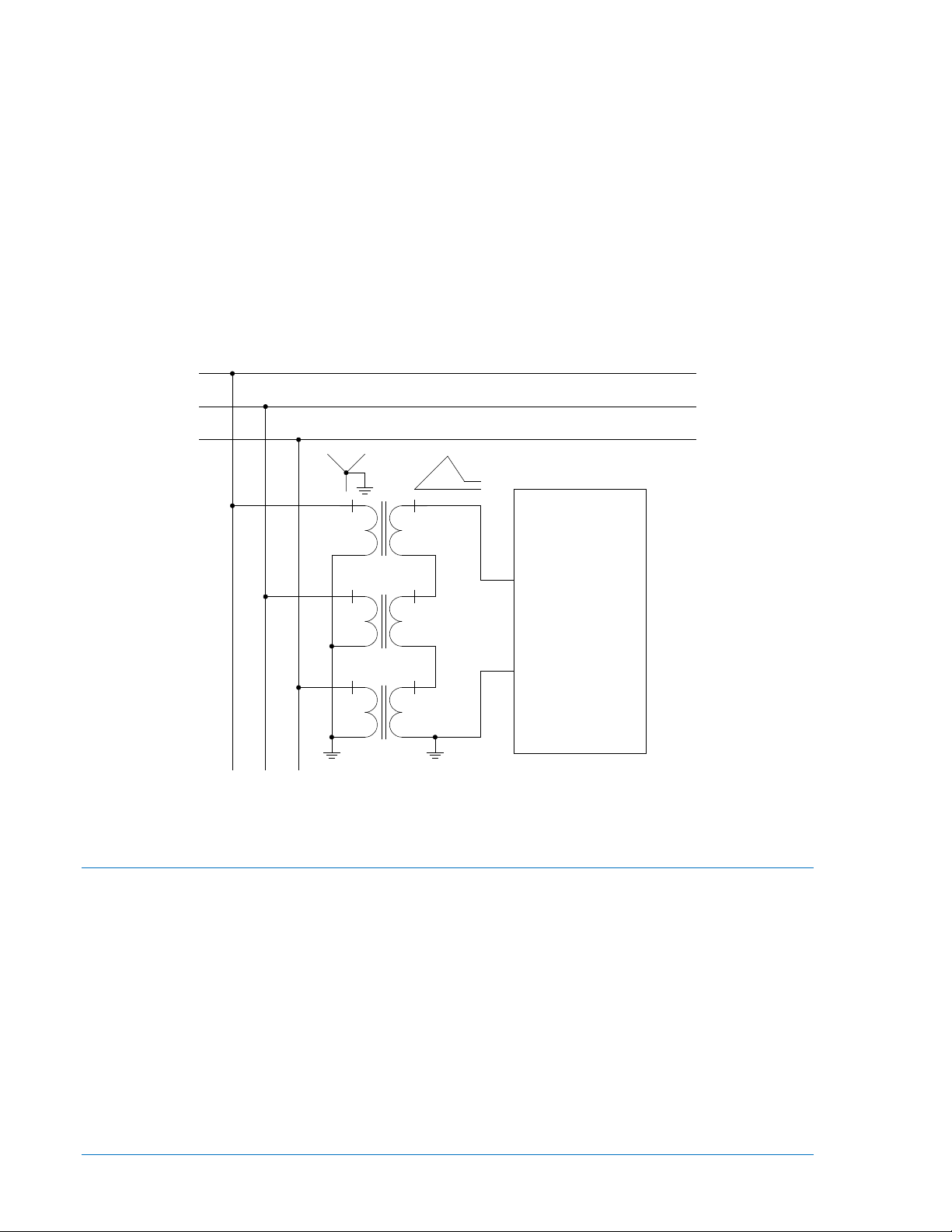
Ground Fault Detection
In a three-phase, three-wire system, a single conductor may break or the insulation may deteriorate
resulting in a high resistance ground fault that may not be detected by the overcurrent relays. This
condition, however, may be sensed by an overvoltage relay connected to a grounded wye, broken delta
set of potential transformers (PT's) as illustrated in Figure 1-1 with this connection, and a sensitive relay
setting, an unbalanced voltage condition such as described above, can be quickly detected and isolated.
Figure 1-1. Ground Fault Detection
Model and Style Number
BE1-27, BE1-59, and BE1-27/59 electrical characteristics and operational features are defined by a
combination of letters and numbers that make up the style number. Model number BE1-27/59 designates
the relay as a Basler Electric Under/Overvoltage Protective Relay. The model number, together with the
style number, describes the options included in a specific device and appears on the front panel, draw-out
cradle, and inside the case assembly.
The style number identification chart for the BE1-27/59 relay is illustrated in Figure 1-2.
1-2 BE1-27/59 General Information 9170600990 Rev L
Page 11
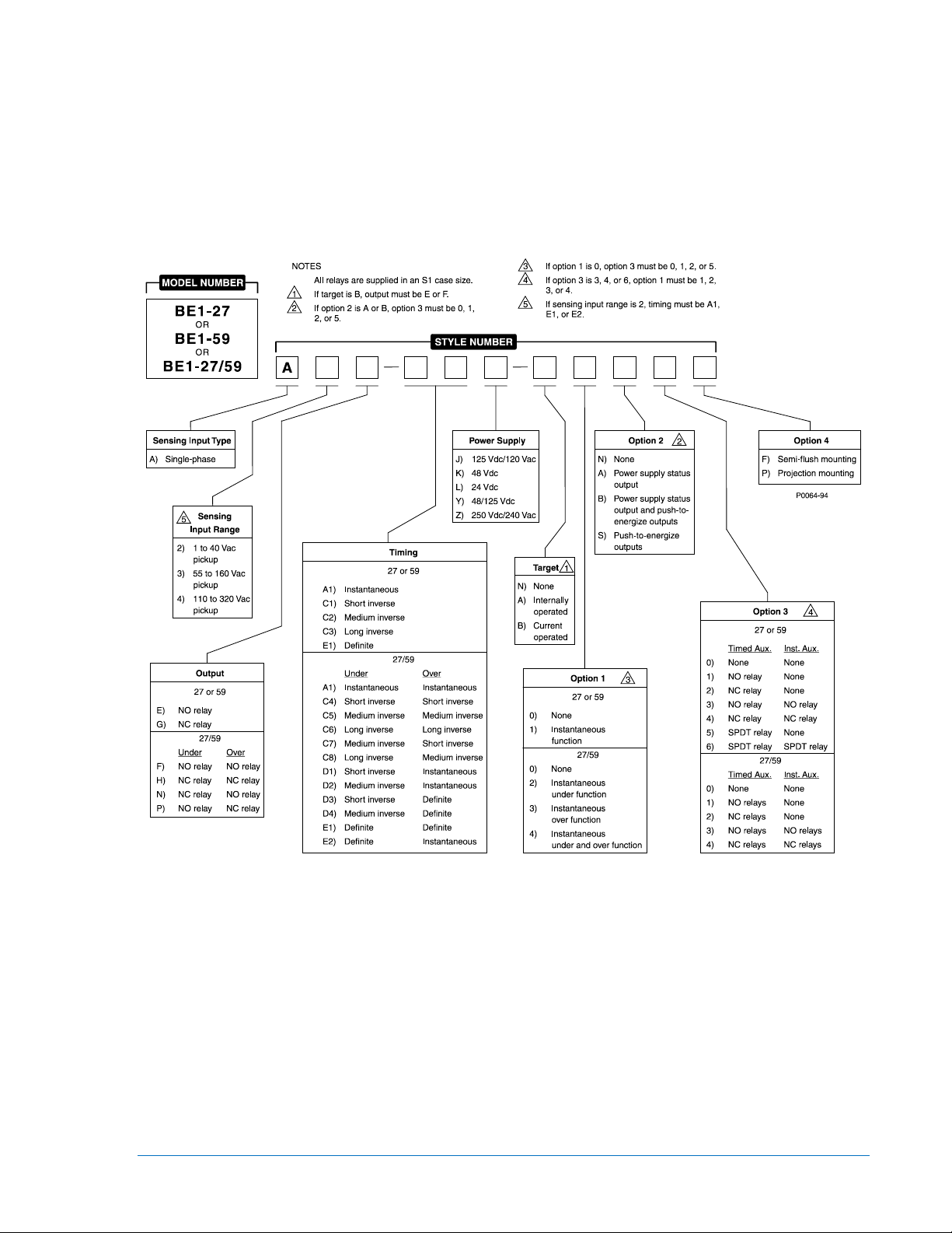
Figure 1-2. Style Number Identification Chart
9170600990 Rev L BE1-27/59 General Information 1-3
Page 12

Style Number Example
If a BE1-27/59 relay has a style number of A3F–E1J–A0S1F, the relay has the following features:
A ------- Single-phase voltage sensing input
3 -------- Sensing input compatible with a pickup adjustment range of 55 to 160 Vac
F -------- 2 normally open output relays (one per function)
E1 ------ Definite timing for each function
J -------- Relay control power is 125 Vdc or 120 Vac, nominal
A ------- Two internally operated target indicators (one per function)
0 -------- No instantaneous functions
S ------- Push-to-energize outputs
1 -------- Two normally-open auxiliary output relays (one per function)
F -------- Semi-flush mounting case
Specifications
Electrical and physical specifications are listed in the following paragraphs.
Voltage Sensing Inputs
Nominally rated at 50/60 Hz, (120/240 V or 100/200 V) with a maximum continuous voltage rating of 360
V (120 V nominal) or 480 V (240 V nominal) at a burden less than 1 VA per phase. Frequency range is
from 40 to 70 Hz.
Undervoltage and Overvoltage Pickup Range
Pickup Range ................................... Continuously adjustable over the range of 1 to 40, 55 to 160, or 110
to 320 Vac as defined by the Style Chart. See Section 3, Functional
Description, System Voltages, for explanation of pickup ranges.
Pickup Accuracy ............................... ±2% or ±0.5 volts of the pickup setting, whichever is greater.
Dropout ............................................. ±2% of pickup.
Timing Characteristics
Instantaneous ................................... Less than 50 milliseconds for a voltage level that exceeds the pickup
setting by 5% or 1 volt, whichever is greater
Definite .............................................. Adjustable from 0.1 to 9.9 seconds, in steps of 0.1 seconds.
Accuracy is ±2% or ±50 milliseconds, whichever is greater. (A setting
of 0.0 provides instantaneous timing.)
Inverse .............................................. Inverse curve types are defined by the Style Chart and are
represented by the curves shown in Section 3, Functional
Description. Inverse time is adjustable from 01 to 99 in increments of
01. Incrementing the time dial varies the inverse curve along the Y
axis. A setting of 00 designates instantaneous timing.
Accuracy is within ±5% or 50 milliseconds (whichever is greater) of
the indicated time for any combination of the time dial setting and
pickup setting and is repeatable within ±2% or 50 ms (whichever is
greater) for any combination of time dial and tap setting. Curves
were generated with Prefault voltage at 10% greater than pickup for
the 27 curves and 10% less than pickup for the 59 curves. For
Prefault voltages that are greater in difference from the pickup
setting, the timing accuracy is ±10% or 100 ms (whichever is
greater).
1-4 BE1-27/59 General Information 9170600990 Rev L
Page 13

Output Contacts
Resistive Ratings
120 Vac ............................................. Make, break, and carry 7 Aac continuously
250 Vdc ............................................. Make and carry 30 Adc for 0.2 s, carry 7 Adc continuously,
break 0.3 Adc
500 Vdc ............................................. Make and carry 15 Adc for 0.2 s, carry 7 Adc continuously,
break 0.3 Adc
Inductive Ratings
120 Vac, 125 Vdc, 250 Vdc .............. Break 0.3 A (L/R = 0.04)
Power Supply
Power supply types and specifications are listed in Table 1-1.
Table 1-1. Power Supply Ratings
Type
K (midrange) 48 Vdc 24 to 150 Vdc 3.8 W
J (midrange)
L (low range) 24 Vdc
Y (midrange)
Z (high range)
* Type L power supply initially requires 14 Vdc to begin operating. Once operating, the input voltage may
be reduced to 12 Vdc and operation will continue.
Nominal
Input Voltage
125 Vdc 24 to 150 Vdc 4.0 W
120 Vac 90 to 132 Vac 17.1 VA
48 Vdc 24 to 150 Vdc 3.8 W
125 Vdc 24 to 150 Vdc 4.0 W
250 Vdc 68 to 280 Vdc 4.1 W
240 Vac 90 to 270 Vac 28.4 VA
Input Voltage
Range
12 to 32 Vdc *
Burden at
Nominal
3.9 W
Target Indicators
Electronically latched, manually reset target indicators are optionally available to indicate closure of the
trip output contacts. Either internally operated or current operated targets may be specified. Internally
operated targets should be selected when normally closed (NC) output contacts are specified.
Current Operated Targets
Minimum Rating ................................ 200 mA flowing through the trip circuit
Continuous Rating ............................ 3 A
1 Second Rating ............................... 30 A
2 Minute Rating................................. 7 A
Type Tests
Shock ................................................ Withstands 15 G in each of three mutually perpendicular planes
without structural damage or performance degradation.
Vibration ............................................ Withstands 2 G in each of three mutually perpendicular planes,
swept over the range of 10 to 500 Hz for a total of six sweeps, 15
minutes each sweep, without structural damage or degradation of
performance.
Dielectric Strength ............................ Tested in accordance with IEC 255-5 and IEEE C37.90: 2,000 Vac
applied for 1 min
Impulse Test ..................................... Qualified to IEC 255-5
9170600990 Rev L BE1-27/59 General Information 1-5
Page 14

Radio Frequency Interference .......... Qualified to IEEE C37.90.2-1995, Standard for Withstand Capability
of Relay Systems to Radiated Electromagnetic Interference from
Transceivers.
Surge Withstand Capability .............. Qualified to IEEE C37.90.1-1989, Standard Surge Withstand
Capability (SWC) Tests for Protective Relays and Relay Systems.
Temperature
Operating Range .............................. –40 to 70°C (–40 to 158°F)
Storage Range .................................. –65 to 100°C (–85 to 212°F)
Physical
Weight ............................................... 14 lbs (6.35 kg)
Case Size ......................................... S1 (See Section 4 for panel cutting/drilling dimensions.)
Agency Recognition/Certification
UL Recognition ................................. UL recognized per Standard 508, File E97033
NOTE: Output contacts are not UL recognized for voltages greater
than 250 volts.
GOST-R Certification ........................ GOST-R certified per the relevant standards of Gosstandart of
Russia.
1-6 BE1-27/59 General Information 9170600990 Rev L
Page 15
SECTION 2 • CONTROLS AND INDICATORS
Introduction
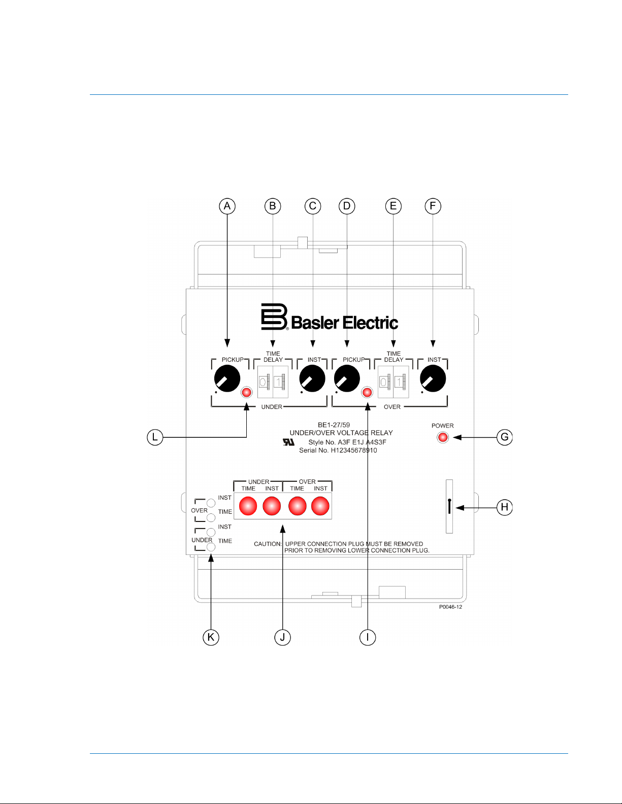
Controls and indicators are located on the front panel. The controls and indicators are shown in Figure
2-1 and described in Table 2-1. Figure 2-1 illustrates a relay with the maximum number of controls and
indicators. Your relay may not have all of the controls and indicators shown and described here.
Figure 2-1. Location of Controls and Indicators
9170600990 Rev L BE1-27/59 Controls and Indicators 2-1
Page 16

Establishes setpoint for the instantaneous
setpoint for the instantaneous
Table 2-1. Control and Indicator Descriptions
Locator Description
A
B
D
E
Undervoltage Pickup Control. Establishes setpoint for the timed undervoltage function.
Continuously adjustable over the range defined by the style number.
Undervoltage Time Delay Control. Establishes the interval between undervoltage pickup
and the time delayed output. Defined by the style number, this delay is either a useradjustable definite time or inversely proportional to the magnitude of the undervoltage
condition. A setting of 0.0 provides an instantaneous response.
Definite - adjustable from 0.0 to 9.9 seconds in 0.1 second increments.
InverseC - adjusts inverse timing characteristic curve relative to the time axis. (See the
characteristic curves in Section 3.)
Undervoltage Instantaneous Control.
undervoltage function. Continuously adjustable over the range defined by the style
number.
Overvoltage Pickup Control. Establishes setpoint for the timed overvoltage function.
Continuously adjustable over the range defined by the style number.
Overvoltage Time Delay Control. Establishes the interval between overvoltage pickup
and the time delayed output. Defined by the style number, this delay is either a useradjustable definite time or inversely proportional to the magnitude of the overvoltage
condition. A setting of 0.0 provides an instantaneous response.
Definite - adjustable from 0.0 to 9.9 seconds in 0.1 second increments.
InverseF - adjusts inverse timing characteristic curve relative to the time axis. (See the
characteristic curves in Section 3.)
Overvoltage Instantaneous Control. Establishes
overvoltage function. Continuously adjustable over the range defined by the style
number.
G Power Indicator. This red LED lights when operating power is applied to the relay.
H Target Reset Switch. This switch is operated to reset the target indicators.
I
J
K
L
Overvoltage Pickup LED. A red LED that illuminates when overvoltage exceeds the
pickup setting.
Target Indicators. The electronically latched red target indicators illuminate when the
corresponding output relay energizes. To ensure proper operation of current-operated
targets, the current flowing through the trip circuit must be 200 mA or higher. Target
indicators are reset by operating the target reset switch (locator H).
Output Test Pushbuttons. These pushbuttons allow manual actuation of the output relays.
Output relay actuation is achieved by inserting a nonconductive rod through the front
panel access holes.
Undervoltage Pickup LED. A red LED that illuminates when undervoltage exceeds the
pickup setting.
2-2 BE1-27/59 Controls and Indicators 9170600990 Rev L
Page 17

SECTION 3 • FUNCTIONAL DESCRIPTION
AUX.
TARGET
AUX.
AUX.
AUX.
POWER
SUPPLY
STATUS
OV TIME
DIAL
OV
TIMER
TIMED
OV
COMPARATOR
OV
PICKUP SETTINGS
INST. TIMED
UNDER OVER
UNDER
OVER
UV TIME
DIAL
UV
TIMER
TIMED
UV
COMPARATOR
UV
INST.
OV
COMPARATOR
INST.
UV
COMPARATOR
POWER
SUPPLY
SENSOR
UV
POWER
SUPPLY
SENSOR
TO INTERNAL
CIRCUITRY
FULL-WAVE
RECTIFIER
LOW-PASS
FILTER
MONITORED
VOLTAGE
OPERATING
POWER
D2354-03
03-11-96
TARGET
TARGET
TARGET
Introduction
BE1-27, BE1-59, and BE1-27/59 relay functions are illustrated in Figure 3-1 and described in the following
paragraphs.
Figure 3-1. Function Block Diagram
System Voltages
The BE1-27, BE1-59, and BE1-27/59 relays are available with three sensing input ranges. The 55 to
160V range is intended for use with nominal system voltages of 120V or 69V (120 ÷ √3). The 110 to 320V
range is intended for use with nominal system voltages of 240V, 208V (120 x √3) or 277V (480 ÷ √3). The
1 to 40V range is intended for use with a wye/broken delta PT configuration with 120V or 69V (120 ÷ √3)
line-to-ground secondary voltages. The wye/broken delta PT configuration is a zero sequence filter
capable of producing three times the line-to-ground voltage (3Vo).
9170600990 Rev L BE1-27/59 Functional Description 3-1
Page 18

Step-Down Transformer
The monitored system voltage is applied to the primary of an internal potential transformer and stepped
down to internal circuit levels. The transformer provides a high degree of isolation.
Low-Pass Filter and Full Wave Rectifier
The output of the step-down transformer is low-pass filtered to prevent undesired response to highfrequency noise. Frequencies above 226 Hz are attenuated. The ac signal is then full-wave rectified to
produce positive-going half-cycles that represent the magnitude of the monitored system voltage.
Pickup Settings
Controlled by front panel single-turn potentiometers, the pickup settings establish reference voltages
representative of the system voltage that will cause the relay to respond. Pickup settings are individually
adjustable for timed under/overvoltage functions and instantaneous under/overvoltage functions. On BE127/59, Under/Overvoltage Relays, the undervoltage function takes precedence over the overvoltage
function.
Pickup Comparators
The output of the rectifier circuit is compared to each pickup setting. When the monitored system voltage
is greater than any pickup setting, the effected comparator’s output goes high. When the monitored
system voltage is less than any pickup setting, the effected comparator’s output goes low. The effects of
these outputs are shown below.
Relevant Pickup Setting
Comparator
High
Low
Undervoltage Overvoltage Undervoltage Overvoltage
No effect Lights OV pickup
Lights UV pickup
indicator; initiates
timer
Timed Instantaneous
No effect Energizes output
indicator; initiates
timer
No effect Energizes output
relay
relay
No effect
Timer Circuit
Once initiated, the timer circuit measures the interval from pickup. If the adverse condition continues
through the programmed delay, the timer circuit energizes the appropriate output relay. In relay styles
with inverse timing, the extent to which the monitored system voltage exceeds the pickup setting
influences the actual time delay such that a greater voltage difference from pickup produces a more rapid
response. This response is illustrated in the characteristic curves as shown in Figures 3-2 through 3-7.
3-2 BE1-27/59 Functional Description 9170600990 Rev L
Page 19

Voltage Difference From Pickup
01
02
03
05
07
10
20
30
40
50
60
80
99
D2857-24
0.1
1.0
100
1000
Range 3
Range 4
0
48
121620
24
28
32
36404448
0
816
243240
48
56
64
72808896
Time in Seconds
10
Figure 3-2. Undervoltage, Short Inverse Timing Characteristic Curve
Figure 3-3. Undervoltage, Medium Inverse Timing Characteristic Curve
9170600990 Rev L BE1-27/59 Functional Description 3-3
Page 20

0.1
1.0
10
1000
Voltage Difference From Pickup
Time in Seconds
01
02
03
05
07
10
20
30
40
50
60
80
99
0
4
8
121620
24
28
32
36404448
0
8
16
243240
48
56
64
72808896
D2857-25
06-09-03
Range 3
Range 4
100
Figure 3-4. Undervoltage, Long Inverse Timing Characteristic Curve
Figure 3-5. Overvoltage, Short Inverse Timing Characteristic Curve
3-4 BE1-27/59 Functional Description 9170600990 Rev L
Page 21

Figure 3-6. Overvoltage, Medium Inverse Timing Characteristic Curve
Figure 3-7. Overvoltage, Long Inverse Timing Characteristic Curve
9170600990 Rev L BE1-27/59 Functional Description 3-5
Page 22

Outputs
27/59 target indicators consisted of
Defined by the style number, the output relays may be provided for each of the following functions: timed
undervoltage, timed overvoltage, instantaneous undervoltage, and instantaneous overvoltage. Auxiliary
output relays may be provided for each of these functions as well. Once energized, output relays will
remain energized until the adverse condition stops.
Push-To-Energize Output Pushbuttons
Small pushbutton switches may be provided as an option to allow testing the primary output contacts and
(if present) the auxiliary output contacts. To prevent accidental operation, the pushbuttons are recessed
behind the front panel and are depressed by inserting a thin, non-conducting rod through an access hole
in the front panel.
Power Supply Status Output
The power supply status relay has a set of normally closed contacts and energizes when operating power
is applied to the relay. If relay operating power is lost or either side of the power supply output (+12 Vdc
or –12 Vdc) fails, the power supply status relay de-energizes and closes the power supply status output
contacts.
Power Supply
Operating power for the relay circuitry is supplied by a wide range, electrically isolated, low-burden power
supply. Power supply operating power is not polarity sensitive. The front panel power LED and power
supply status output indicate when the power supply is operating. Power supply specifications are listed in
Table 1-1.
Target Indicators
Target indicators are optional components selected when a relay is ordered. The electronically latched
and reset targets consist of red LED indicators located on the relay front panel. A latched target is reset
by operating the target reset switch on the front panel. If relay operating power is lost, any illuminated
(latched) targets are extinguished. When relay operating power is restored, the previously latched targets
are restored to their latched state.
A relay can be equipped with either internally operated targets or current operated targets.
Internally Operated Targets
The relay trip outputs are directly applied to drive the appropriate target indicator. Each indicator is
illuminated regardless of the current level in the trip circuit.
Current Operated Targets
A current operated target is triggered by closure of the corresponding output contact and
at least 200 milliamperes of current flowing in the trip circuit.
NOTE
Prior to September 2007, BE1magnetically latched, disc indicators. These mechanically latched target
indicators have been replaced by the electronically latched LED targets in use
today.
the presence of
3-6 BE1-27/59 Functional Description 9170600990 Rev L
Page 23

SECTION 4 • INSTALLATION
When the relay is configured in a system with other devices, it is
Introduction
The relays are shipped in sturdy cartons to prevent damage during transit. Upon receipt of a relay, check
the model and style number against the requisition and packing list to see that they agree. Inspect the
relay for shipping damage. If there is evidence of damage, file a claim with the carrier, and notify your
sales representative or Basler Electric.
If the relay will not be installed immediately, store it in its original shipping carton in a moisture- and dustfree environment. Before placing the relay in service, it is recommended that the test procedures of
Section 5, Testing be performed.
Relay Operating Guidelines and Precautions
Before installing or operating the relay, note the following guidelines and precautions.
● For proper current operated target operation, a minimum current of 200 milliamperes must flow
through the output trip circuit.
● If a wiring insulation test is required, remove the connection plugs and withdraw the relay from its
case.
● An undervoltage target indication may occur when the lower connection paddle is removed if:
○ The instantaneous time function is selected, or
○ A time delay (definite or inverse) below 0.3 seconds is selected.
○ No actual trip output occurs if the upper paddle is removed first.
CAUTION
When the connection plugs are removed, the relay is disconnected from the
operating circuit and will not provide system protection. Always be sure that
external operating (monitored) conditions are stable before removing a relay
for inspection, test, or service.
NOTE
Be sure that the relay is hard-wired to earth ground with no smaller than 12
AWG copper wire attached to the ground terminal on the rear of the case.
recommended to use a separate lead to the ground bus from each device.
Mounting
Because the relay is of solid-state design, it does not have to be mounted vertically. Any convenient
mounting angle may be chosen.
A panel cutting/drilling diagram for a semi-flush, S1 case is illustrated in Figure 4-1. An outline of the case
cover is shown around the cut-out. Relay outline dimensions and panel drilling diagrams are illustrated in
Figures 4-2 through 4-12.
9170600990 Rev L BE1-27/59 Installation 4-1
Page 24

0.552
(14)
8.63
(219)
0.480
(12)
Outer Edge of Cover
Cut-Out
5.69 (144)
0.480
(12)
8.25
(210)
C
L
0.575
(15)
0.25 (6) diameter, 4 places
Figure 4-1. Panel Cutting/Drilling, Semi-Flush, S1 Case
6.06 (154)
3.03 (77)
4.13
(105)
P0072-12
4-2 BE1-27/59 Installation 9170600990 Rev L
Page 25

Figure 4-2. S1 Case Dimensions, Rear View, Double Ended, Semi-Flush Mount
9170600990 Rev L BE1-27/59 Installation 4-3
Page 26

.75
(19.1)
(157.2)
6.19
(49.53)
1.95
10-32 SCREWS
(7.9)
.31
10-32 SCREWS
(102.4)
4.03
4.03
(102.4)
(7.9)
.31
MOUNTING PANEL
(55.75)
2.195
P0066-64
Figure 4-3. S1 Case Dimensions, Side View, Double Ended, Semi-Flush Mount
4-4 BE1-27/59 Installation 9170600990 Rev L
Page 27

Figure 4-4. S1 Case Dimensions, Rear View, Single Ended, Semi-Flush Mount
9170600990 Rev L BE1-27/59 Installation 4-5
Page 28

.75
(19.1)
(157.2)
6.19
(49.53)
1.95
10-32 SCREWS
MOUNTING PANEL
(55.75)
2.195
P0066-69
8.06
(204.72)
(7.9)
.31
Figure 4-5. S1 Case Dimensions, Side View, Single Ended, Semi-Flush Mount
4-6 BE1-27/59 Installation 9170600990 Rev L
Page 29

Figure 4-6. Panel Cutting/Drilling, Double Ended, Projection Mount, S1 Case
9170600990 Rev L BE1-27/59 Installation 4-7
Page 30

Figure 4-7. S1 Case Dimensions, Rear View, Double Ended, Projection Mount
4-8 BE1-27/59 Installation 9170600990 Rev L
Page 31

.75
(19.1)
(157.2)
6.19
(49.53)
1.95
10-32 SCREWS
(7.9)
.31
10-32 SCREWS
(102.4)
4.03
4.03
(102.4)
(7.9)
.31
(55.75)
2.195
P0066-67
TERMINAL EXTENSION (TYP.)
FOR DETAILED INSTRUCTIONS,
SEE THE TERMINAL PROJECTION
MOUNTING KIT SUPPLIED.
.25
(6.4)
5/16-18 STUD
2 PLACES
MOUNTING PANEL
Figure 4-8. S1 Case Dimensions, Side View, Double Ended, Projection Mount
9170600990 Rev L BE1-27/59 Installation 4-9
Page 32

Figure 4-9. Panel Cutting/Drilling, Single Ended, Projection Mount, S1 Case
4-10 BE1-27/59 Installation 9170600990 Rev L
Page 33

Figure 4-10. S1 Case Dimensions, Rear View, Single Ended, Projection Mount
9170600990 Rev L BE1-27/59 Installation 4-11
Page 34

(157.2)
6.19
(49.53)
1.95
10-32 SCREWS
MOUNTING PANEL
(55.75)
2.195
P0066-71
TERMINAL EXTENSION (TYP.)
FOR DETAILED INSTRUCTIONS,
SEE THE TERMINAL PROJECTION
MOUNTING KIT SUPPLIED.
.25
(6.4)
5/16-18 STUD
2 PLACES
MOUNTING PANEL
8.06
(204.72)
(7.9)
.31
.75
(19.1)
Figure 4-11. S1 Case Dimensions, Side View, Single Ended, Projection Mount
4-12 BE1-27/59 Installation 9170600990 Rev L
Page 35

P0066-68
Figure 4-12. S1 Case Cover Dimensions, Front View
9170600990 Rev L BE1-27/59 Installation 4-13
Page 36

Connections
Be sure to check the model and style number of a relay before connecting and energizing the relay.
Incorrect wiring may result in damage to the relay. Except where noted, connections should be made with
wire no smaller than 14 AWG.
Typical internal connections are shown in Figures 4-13 through 4-15. Typical ac connections are shown in
Figure 4-16. Typical dc connections are shown in Figure 4-17.
Figure 4-13. BE1-27 Internal Connections
4-14 BE1-27/59 Installation 9170600990 Rev L
Page 37

Figure 4-14. BE1-59 Internal Connections
9170600990 Rev L BE1-27/59 Installation 4-15
Page 38

Figure 4-15. BE1-27/59 Internal Connections
4-16 BE1-27/59 Installation 9170600990 Rev L
Page 39

Figure 4-16. Typical AC Connections
9170600990 Rev L BE1-27/59 Installation 4-17
Page 40

Figure 4-17. Typical DC Connections
4-18 BE1-27/59 Installation 9170600990 Rev L
Page 41

Maintenance
BE1-27, BE1-59, and BE1-27/59 relays require no preventative maintenance other than a periodic
operational check. If the relay fails to function properly, contact Technical Sales Support at Basler Electric
to coordinate repairs.
Storage
This device contains long-life aluminum electrolytic capacitors. For devices that are not in service (spares
in storage), the life of these capacitors can be maximized by energizing the device for 30 minutes once
per year.
9170600990 Rev L BE1-27/59 Installation 4-19
Page 42

4-20 BE1-27/59 Installation 9170600990 Rev L
Page 43

SECTION 5 • TESTING
Introduction
The following procedures verify proper relay operation and calibration.
Results obtained from these procedures may no fall within specified tolerances. When evaluating results,
consider three prominent factors:
• Test equipment accuracy
• Testing method
• External test set components tolerance level
Required Test Equipment
Minimum test equipment required for relay testing and adjustment is listed below. Refer to Figure 5-1 for
the test setup.
NOTE
Commercially available frequency relay test sets with frequency and time
generating accuracies exceeding those of the relay and including electronic
switching, may be used.
• Appropriate ac or dc power source for relay operation.
• Appropriate ac source for frequency sensing. (A source with frequency stability of 0.00002 Hz
must exhibit phase noise of less than 90 db for accurate measurement. The accuracy and
stability of this source is necessary as the relay precisely measures the period between positive
going zero-crossings of the applied waveform and responds instantaneously to the sensed
condition.)
• Hardware (battery and lamp, multimeter, etc.) or method of determining that the output contacts
close.
Operational Test
Power Supply Status Output (Option 2-A or B)
Step 1. With the unit in a powered-up condition, verify that the power supply status output contacts
are energized open.
Step 2. Remove input power and verify that the status output contacts close.
Pickup
Step 1. Connect the test circuits shown in Figure 5-1 as necessary for the functions included in your
relay model. See Table 5-1. Turn all undervoltage pickup controls fully CCW and all
overvoltage pickup functions fully CW. Set all time delay controls to 00. Adjust T1 to nominal
voltage for your sensing input range as indicated below.
Table 5-1. Sensing Input Range
Sensing Input Range
2 3 4
120 Vac 120 Vac 240 Vac
9170600990 Rev L BE1-27/59 Testing 5-1
Page 44

NOTE
V
3
4
6
7
12
11
13
10
2
1
OPERATING
POWER
AC
SOURCE
BE1-27, 59,
27/59
+
D2816-15
Results assume normally open output contacts. Test indicator states will be
opposite for normally closed output contacts.
Figure 5-1. Pickup and Dropout Test Circuit Diagram
Figure 5-2. Timing Test Circuit Diagram
5-2 BE1-27/59 Testing 9170600990 Rev L
Page 45

RESULTS: In relays with Sensing Input Range 2, the OVER PICKUP indicator is illuminated as well as
the timed and instantaneous overvoltage test indicators. In units with Sensing Input Range 3 or 4, all
pickup and test indicators will be extinguished.
Table 5-2. Output Terminals
Pickup Function
Timed Undervoltage 1-10
Instantaneous Undervoltage 2-10
Timed Overvoltage
Instantaneous Overvoltage
NOTE
Steps 2 through 4 apply only to units with Sensing Input Range 2.
Step 2. Slowly decrease the T1 voltage until the OVER PICKUP indicator and the timed and
instantaneous overvoltage test indicators extinguish. Slowly increase the T1 voltage until the
OVERVOLTAGE PICKUP indicator and the timed and instantaneous overvoltage test
indicators illuminate. Record the voltage.
RESULT: This voltage is between 39.2 and 40.8 Vac.
Step 3. Turn the timed and instantaneous OVERVOLTAGE PICKUP controls fully CCW. Slowly
decrease the T1 voltage until the OVERVOLTAGE PICKUP indicator and the timed and
instantaneous test indicators extinguish.
Step 4. Slowly increase the voltage at T1 until the OVERVOLTAGE PICKUP indicator and the timed
and instantaneous overvoltage test indicators illuminate. Measure and record the voltage.
RESULT: This voltage is between 0.5 and 1.5 Vac.
This concludes the pickup test for units with Sensing Input Range 2.
Relay Model
27 59 27/59
2-10
12-13
—
—
—
—
1-10 1-10
2-10 11-13
NOTE
Steps 5 and 6 apply only to undervoltage functions.
Step 5. Slowly decrease the voltage at T1 until the UNDER PICKUP indicator and the timed and
instantaneous test indicators illuminate. Measure and record the voltage.
RESULT: The voltage is between 53.9 and 56.1 Vac for Sensing Input Range 3 or between 107.8 and
112.2 Vac for Sensing Input Range 4.
Step 6. Increase T1 voltage to 170 Vac for Sensing Input Range 3 or 330 Vac for Sensing Input
Range 4. Turn all undervoltage pickup controls fully CW. Slowly decrease T1 voltage until
the UNDER PICKUP indicator and timed and instantaneous undervoltage test indicators
illuminate. Measure and record the voltage.
RESULT: This voltage is between 156.8 and 163.2 Vac for Sensing Input Range 3 or between 313.6
and 326.4 for Sensing Input Range 4.
This concludes the pickup test for the undervoltage functions.
NOTE
Steps 7 and 8 apply only to overvoltage functions.
9170600990 Rev L BE1-27/59 Testing 5-3
Page 46

Step 7. Slowly increase the T1 voltage until the OVER PICKUP indicator and the timed and
instantaneous overvoltage test indicators illuminate. Measure and record the voltage.
RESULT: This voltage is between 156.8 and 163.2 Vac for Sensing Input Range 3 or between 313.6
and 326.4 for Sensing Input Range 4.
NOTE
Step 8 applies only to BE1-59 relays with Sensing Input Range 3 or 4.
Step 8. Decrease the T1 voltage to 50 Vac. Turn all overvoltage pickup controls fully CCW. Slowly
increase the T1 voltage until the OVER PICKUP indicator and the timed and instantaneous
overvoltage test indicators illuminate. Measure and record the voltage.
RESULT: The voltage is between 53.9 and 56.1 Vac for Sensing Input Range 3 or between 107.8 and
112.2 Vac for Sensing Input Range 4.
This concludes the pickup test.
Timing
The following procedure verifies timing characteristics.
Step 1. Connect the test circuit shown in Figure 5-2. Output terminal connections are dependent on
the function to be tested. See Table 5-1.
Step 2. Adjust the under or overvoltage pickup settings and the T1 and T2 tap voltage levels as
indicated in Table 5-3 below for the function being tested.
Table 5-3. T1 and T2 Tap Voltage Levels
Sensing
Range
2 30
Over
Pickup
Under
Pickup
—
T1
Voltage
20 40
T2
Over Under
—
3 120 100 110 152 68
4 240 200 220 304 136
Step 3. Set the time delay control for the function being tested to 00 (50 ms or less). Press and
release S2 to assure that K1 is de-energized. Reset the timer. Press and release S1.
RESULT: The timer displays a response time, dependent on timing type, as indicated in Column 1 of
Table 5-4.
Table 5-4. Timing Test Results
Timing Type Column 1 Column 2
Instantaneous 50 ms or less 50 ms or less
Definite 0.050 to 0.150 sec 9.702 to 10.098 sec
Short Inverse 0.087 to 0.187 sec 0.092 to 0.192 sec 6.231 to 6.687 sec 6.557 to 7.247 sec
Under Over Under Over
Medium Inverse 0.292 to 0.392 sec 0.307 to 0.407 sec 24.626 to 27.218 sec 25.991 to 28.727 sec
Long Inverse 0.553 to 0.653 sec 0.583 to 0.683 sec 49.185 to 54.363 sec 51.895 to 57.358 sec
5-4 BE1-27/59 Testing 9170600990 Rev L
Page 47

Step 4. Set the time delay control for the function being tested to 01 (0.1 seconds). Press and
release S2 to assure that K1 is de-energized. Reset the timer. Press and release S1.
RESULT: The timer displays a response time, dependent on timing type, as indicated in Column 1 of
Table 5-4.
Step 5. Press and release S2. Set the time delay control for the function being tested to 99 (9.9
seconds). Reset the timer. Press and release S1.
RESULT: The timer displays a response time, dependent on timing type, as indicated in Column 2 of
Table 5-4.
Step 6. Repeat Steps 1 through 5, as necessary, for each function’s time delay control.
This concludes the operational test procedure.
9170600990 Rev L BE1-27/59 Testing 5-5
Page 48

5-6 BE1-27/59 Testing 9170600990 Rev L
Page 49

Page 50

12570 State Route 143
P.A.E. Les Pins
No. 59 Heshun Road Loufeng District (N)
111 North Bridge Road
Highland IL 62249-1074 USA
Tel: +1 618.654.2341
Fax: +1.618.654.2351
email: info@basler.com
67319 Wasselonne Cedex
FRANCE
Tel: +33 3.88.87.1010
Fax: +33 3.88.87.0808
email: franceinfo@basler.com
Suzhou Industrial Park
215122 Suzhou
P.R. CHINA
Tel: +86 512.8227.2880
Fax: +86 512.8227.2887
email: chinainfo@basler.com
15-06 Peninsula Plaza
Singapore 179098
Tel: +65 68.44.6445
Fax: +65 68.44.8902
email: singaporeinfo@basler.com
 Loading...