

Page 1
INSTRUCTION MANUA L
FOR
AUTO SYNCHRONIZER
BE1-25A
Publication: 9146600990
Revision: S 10/14
Page 2

Page 3

INTRODUCTION
This instruction manual provides information about the operation and installation of the BE1-25A Auto
Synchronizer. To accomplish this, the following information is provided:
• General Information and Specifications
• Controls and Indicators
• Functional Description
• Installation
• Maintenance
WARNING!
To avoid personal inj ury or equipment damage, only qualified personnel should
perform the procedures in this manual.
NOTE
Be sure that the BE1-25A is hard-wired to earth ground w ith no smaller tha n 12
AWG copper wire attache d to the ground terminal on the rear of the unit case.
When the BE1-25A is configured in a system with other devices, it is
recommended to use a separate lead to the ground bus from each unit.
9146600990 Rev S BE1-25A Introduction i
Page 4

First Printing: July 1985
WARNING
Basler Electric does not assume any responsibility to compliance or noncompliance with national code,
understood prior to installation, operation, or maintenance.
For terms of service relating to this product and software, see the Commercial Terms of Products and
Services document available at www.basler.com/terms.
This publication contains confidential information of Basler Electric Company, an Illinois corporation. It
procedures, contact Basler Electric for the latest revision of this manual.
The English-language version of this manual serves as the only approved manual version.
Printed in USA
© 2014 Basler Electric, Highland Illinois 62249 USA
All Rights Reserved
October 2014
READ THIS MANUAL. Read this manual before installing, operating, or maintaining the BE1-25A.
Note all warnings, cautions, and notes in this manual as well as on the product. Keep this manual with
the product for reference. Only qualified personnel should install, operate, or service this system.
Failure to follow warning and cautionary labels may result in personal injury or property damage.
Exercise caution at all times.
local code, or any other applicable code. This manual serves as reference material that must be well
is loaned for confidential use, subject to return on request, and with the mutual understanding that it will
not be used in any manner detrimental to the interests of Basler Electric Company and used strictly for
the purpose intended.
It is not the intention of this manual to cover all details and variations in equipment, nor does this
manual provide data for every possible contingency regarding installation or operation. The availability
and design of all features and options are subject to modification without notice. Over time,
improvements and revisions may be made to this publication. Before performing any of the following
BASLER ELECTRIC
12570 STATE ROUTE 143
HIGHLAND IL 62249 USA
http://www.basler.com, info@basler.com
PHONE +1 618.654.2341 FAX +1 618.654.2351
ii BE1-25A Introduction 9146600990 Rev S
Page 5

REVISION HISTORY
Revision and Date
Change
The following informat ion provides a historical su mmary of the ch anges made t o the BE1-25A instruction
manual (9146600990). Revisions are listed in reverse chronological order.
Manual
S, 10/14
R, 03/11
Q
P, 05/10
O
N, 12/09
• Added note about sync output closure in Sections 1 and 5.
• Added note about Reset switch functionality in Sections 2 and 5.
• Updated the MCU Sync Module Readings label in Figures 2-1, 2-2,
5-2, and drawing on front cover.
• This revision letter not used.
• Corrected definition of 3. POWER under Locator B in Table 2-1.
• Improved definition of SYNC LED under Locator M in Table 2-1.
• Updated Storage stat em ent in Section 4.
• Improved Verification and Calibration procedure in Section 5.
• This revision letter not used.
Section 2
• Updated Additional Modules, Frequency Matching Module F5
description.
• Updated Additional Modules, Frequency Matching Module F5, F1
Function, Pulse Contact Closure description.
• Updated Additional Modules, Frequency Matching Module F5, F3
Function, Continuous Correction Pulse description.
• Under Additional Modules, Frequency Matching Module F5, F5
Proportional Frequency Correction, changed “+12 Vdc = raise pulse;
−12 Vdc = lower pulse” to “+5 Vdc = raise pulse; −5 Vdc = lower
pulse”.
• Under Additional Modules, Frequency Matching Module F5, F5 Phase
Correction, changed “+12 Vdc = raise pulse; −12 Vdc = lower pulse”
to “+5 Vdc = raise pulse; −5 Vdc = lower pulse” and removed
sentence “The frequency of the target pulses is approximately 1.5
percent of the correction pulse width setting loaded into the
microprocessor.”
Section 3
• Corrected numbering of Figures. Figure 3-6 was skipped.
• Under Frequency Matching Modules, Frequency Correction, changed
“+12 Vdc = raise pulse; −12 Vdc = lower pulse” to “+5 Vdc = raise
pulse; −5 Vdc = lower pulse”.
• Under Frequency Matching Modules, Phase Correction, changed
“+12 Vdc = raise pulse; −12 Vdc = lower pulse” to “+5 Vdc = raise
pulse; −5 Vdc = lower pulse” and removed sentence “The frequency
of the target pulses is approximately 1.5 percent of the correction
pulse width setting loaded into the microprocessor.”
Section 4
• Deleted Dielectric Test. This is in Section 5, Testing.
• Added Maintenance and Storage from original Section 6.
Section 6
• Moved Section 7, Relay Differences to Section 6, Relay Differences.
• Corrected references to several figures.
9146600990 Rev S BE1-25A Introduction iii
Page 6

Manual
Revision and Date
Change
M, 05/08
L, 06/06
K, 05/05
J, 11/99
I
H, 08/98
G, 10/97
F, 07/96
E, 03/94
D
C
B
A
—, 07/85
• Corrected Max Slip Control range in Sections 1 & 2.
• Corrected Breaker Operating Time range in Section 2.
• Added manual part number and revision to footers.
• Corrected wording in Section 2 paragraph describing F3 function.
• Added metric weights to the specifications of Section 1.
• Changed name of the glossary to Appendix A, Glossary.
• Moved contents of Section 8, Manual Change Information, to the
• Changed all front panel illustrations to reflect changes to the panel of
• Updated Figure 4-1 to show new front panel and dimensions.
• Updated Figure 4-2 to show height of panel cutout.
• Added UL and CSA data to the specifications.
• In the cutout dimensions illustration, added clearance holes for
• This revision letter not used.
• Added US patent declaration to the specifications.
• Updated the manual format.
• Made various, minor changes to text.
• Revisions made to accommodate changes to firmware (version 5.02)
• Revised manual in response to option F5 being made standard.
• Divided Installation and Testing section into two sections.
• Changed all front panel illustrations to reflect changes in the controls
• Changed all references to voltage difference adjustment (option A2)
• Corrected dead bus VOLTS control from dc to ac.
• Deleted note attached to the SLIP HIGH LED.
• Added manual change information sec t ion to the man u al.
• Specification for max slip adjustment was corrected.
• Specification for isolation added.
• UL and CSA approval cited.
• Test procedures simplified.
• Manual completely revised to reflect the incorporation of a
• Relay differences section added.
• General editorial revisions.
• Initial release
manual introduction and deleted Section 8.
the power supply module.
attaching the cover.
which improved the performance of F1 and F3 type frequency
correction.
and indicators.
from 1-50 Vac to 1-10 Vac .
microprocessor in the synchronizer module (renamed the MCU Sync
module), and related changes beginning with product serial number
300.
iv BE1-25A Introduction 9146600990 Rev S
Page 7

CONTENTS
SECTION 1 • GENERAL INFORMATION ................................................................................................ 1-1
SECTION 2 • HUMAN-MACHINE INTERFACE ....................................................................................... 2-1
SECTION 3 • FUNCTIONAL DESCRIPTION ........................................................................................... 3-1
SECTION 4 • INSTALLATION .................................................................................................................. 4-1
SECTION 5 • TESTING ............................................................................................................................ 5-1
SECTION 6 • RELAY DIFFERENCES...................................................................................................... 6-1
APPENDIX A • GLOSSARY ..................................................................................................................... A-1
9146600990 Rev S BE1-25A Introduction v
Page 8

This page intentionally left blank .
vi BE1-25A Introduction 9146600990 Rev S
Page 9

SECTION 1 • GENERAL INFORMATION
TABLE OF CONTENTS
SECTION 1 • GENERAL INFORMATION ................................................................................................ 1-1
DESCRIPTION ...................................................................................................................................... 1-1
OPTIONS ............................................................................................................................................... 1-1
MULTI-GENERATOR OPERATION ...................................................................................................... 1-1
APPLICATION ....................................................................................................................................... 1-2
General ............................................................................................................................................... 1-2
Generator-to-Bus Applicat i on ............................................................................................................. 1-2
Bus-to-Bus Application ....................................................................................................................... 1-2
Application Checklist .......................................................................................................................... 1-3
Defining the Parameters..................................................................................................................... 1-4
MODEL AND STYLE NUMBER............................................................................................................. 1-5
SPECIFICATIONS ................................................................................................................................. 1-6
SPECIFICATIONS OF OPTIONS .......................................................................................................... 1-8
Voltage Acceptance Option A1 .......................................................................................................... 1-8
Voltage Acceptance Option A2 .......................................................................................................... 1-8
Frequency Matching Option F5 .......................................................................................................... 1-8
Voltage Matching Option V1............................................................................................................... 1-8
Voltage Matching Option V2............................................................................................................... 1-8
Voltage Matching Option V3............................................................................................................... 1-8
Dead Bus Option D1 .......................................................................................................................... 1-8
Figures
Figure 1-1. Slip, Advance Angle, and Breaker Clos in g Time .................................................................... 1-4
Figure 1-2. Style Number Identification Chart ........................................................................................... 1-5
9146600990 Rev S BE1-25A General Information i
Page 10

This page intentionally left blank .
ii BE1-25A General Information 9146600990 Rev S
Page 11

SECTION 1 • GENERAL INFORMATION
DESCRIPTION
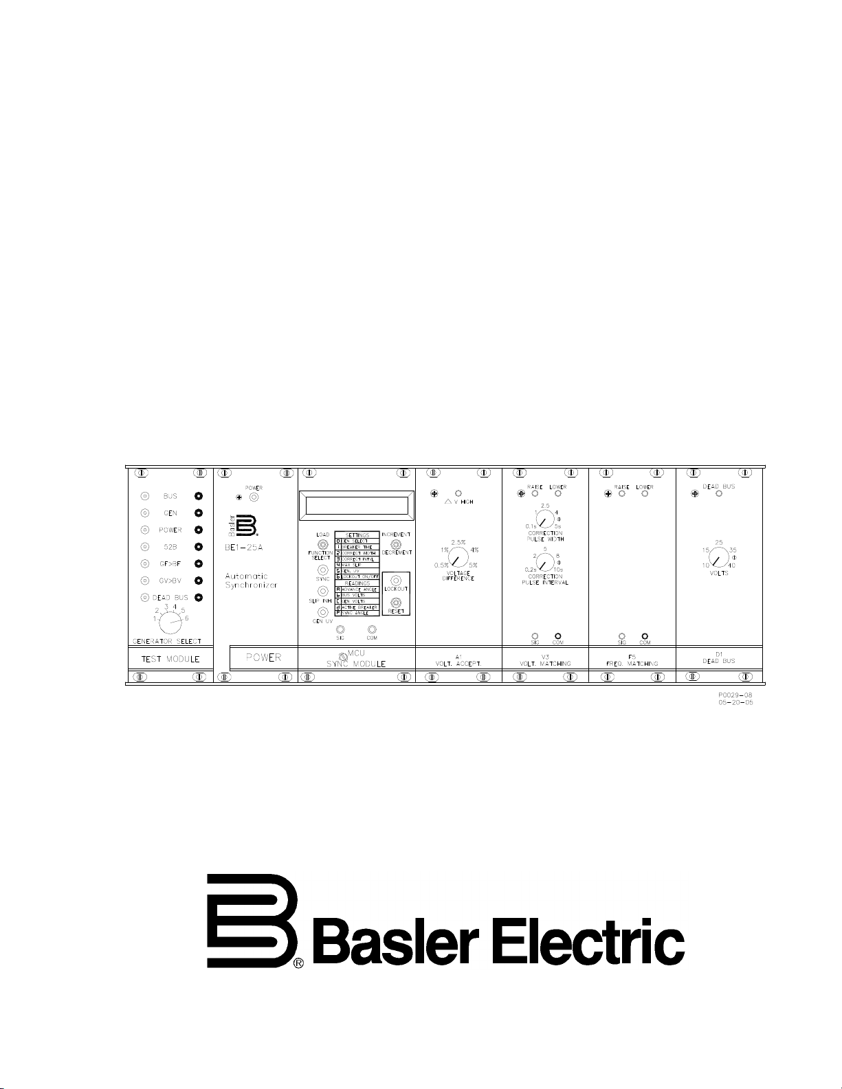
A basic BE1-25A Auto-Sy nchronizer consists of three rack -mounted modules that determine the proper
time to in itiate c los ing of a break er to paral lel a gen erator and a bus . The thr ee s tand ard m odules are t he
master control unit ( MCU) s ync modu le, the test module, and t he pow er s upply. Optio nal p lug-in mod ules
are available for installation (at initial purchase, or at any later time) to enhance this basic capability.
Among the options are the frequency matching and v oltage matching modules t hat direct the generator
control system to adjust vol tage or frequency ( or both) to meet sys tem requireme nts. The unit is not tru ly
an automatic synchronizer unless one or more of the matching options is incorporated.
An ideal closing is one that minimizes electrical and mechanical transients. Because the ideal closing
occurs when the voltages are in phase, the initiating signal must be delivered ahead of phase coincidence
by a factor equal to the operating speed of the breaker. This factor (termed the advance angle) is
calculated by the M CU sync module. This module is essentially a d edicated computer tha t monitors the
voltages on both sides of t he breaker to be closed, calculates th e slip frequency, and then (taking int o
consideration the operating speed of the breaker) calculates the required advance angle.
Closure will occur only if the slip frequency is less than the limit established by the slip setting. Once
breaker closure has been initiated, the BE1-25 A is inhibited from further operat ion for a minimum of 15
seconds. If the breaker reopens dur ing this 15-second inhibit period, the unit enter s a lockout condition
that prevents further operation until the unit is reset.
OPTIONS
Plug-in options can extend the capability of the basic unit. These are briefly summarized here as to
overall function. (They are explained in detail in the later sections of this manual.)
• A voltage acceptance module may be added to the basic synchronizer to assure that the
oncoming generator voltage is withi n a pre-selected magnitude with respect to the bus voltag e
before breaker closur e is allowed. Th is option is required if o ne of the vo ltage matc hing modules
is to be used.
• Voltage matching modules provide RAISE and LOWER signals to the voltage regulator of the
oncoming generator to bring the machine voltage within the limits defined by the voltage
acceptance module.
• Frequency matching (i.e., speed control) module provides RAISE and LOWER signals to the
governor to bring the oncoming generator s peed to within the slip frequency limit that is preset
into the Auto-Synchronizer. If the slip is very smal l and the p hase ang le is large, a target puls e is
initiated to change the generator speed in the direction of the closest phase coincidence.
• A dead bus module allows selection of various low bus voltage conditions to enable breaker
closing without synchronization. This provides a black start capability for the system.
MULTI-GENERATOR OPERATION
BE1-25A relays can contr ol more than one ge nerator by simultaneo usly switchin g all of the relay relevant
inputs and outputs fr om one generator to t he next. Those inputs a nd outputs are: the generator sensing
voltage, breaker 52b and closing coil circuits, and the leads associated with options (such as the
frequency and voltage matching lines to regulator or governor). All of these must be switched
simultaneously by a ganged switch called the synchronizing select switch. (This switch is installed
external to the BE1-25A un it, and is not supp lied with t he relay. Inst allation d etails are giv en in Section 4 ,
Installation.)
In addition to the re lay relevant inputs and output s, settings for the system oper ational parameters are
entered using the MCU fro nt panel LOAD/FUNCTION select switc h. Settings for six generator systems
can be entered and stored into MCU memory.
9146600990 Rev S BE1-25A General Information 1-1
Page 12

APPLICATION
General
From large, single or multip le generator s to sma ll, mult iple-unit a pplications , slip fr equenc y synchr onizers
such as the BE1-25A provide fas t, accurate, synchronization of g enerator-to-bus or bus-to-bus break er
closures if a slip rate exists between the two s ides of the open break er. For the BE1-25A to be capable of
closing the breaker, the ph as e ang le bet wee n the tw o v oltag e in put s must first pass through 180 elec tric a l
degrees and maintain a slip rate until the synchronizer issues a breaker close signal.
Excluded from this discussion are phase lock type synchronizers (such as the BE3-25A) that do not
require nor allow a slip to occur between the oncoming generator and the bus.
Generator-to-Bus Application
For a slip frequency sync hronizer to oper ate pr op er ly i n a gener at or -to-bus application, the followi ng list ed
operational parameters are entered into the memory of the synchronizer using the front panel
LOAD/FUNCTION select switch.
• Generator breaker closing time (calculates advance angle)
• Generator speed correction pulse width(maximum correction pulse width)
• Generator speed correction pulse interval (maximum correction pulse interval)
• Maximum slip frequency (maximum slip frequency and still allow breaker closing)
• Generator undervoltage (inhibits synchronization below this limit)
• Lockout ON/OFF (arms or disarms lockout feature)
Synchronization is enabled when the slip frequency is less than the maximum slip setting and the
generator voltage is greater than the generator undervoltage setting. Synchronization is NOT enabled
(inhibited) when th e slip fr equency is greater than the maxim um slip s etting, th e generat or voltage is less
than the generator u ndervoltage setting, or a lockout condition exists. If a voltage acceptance optio n is
included, synchronization is NOT enabled if the bus voltages are out of limits, the voltage difference
between generator and b us is greater than the setting, or the p hase angle difference is greater than the
calculated advance angle. If a dead bus option is included, immediate sync hronization is enabled if the
bus voltage is less than the setting and the dead bus enable input is closed.
When generator spee d correction pulses are required, pr oportional pulses are generated bas ed on the
slip frequency and the max imum slip freque ncy s etting. If the slip freq uency is gre ater than four times the
maximum slip frequenc y setting, proportional pulse are generat ed that are equal to 100 percent of the
correction pulse wi dth. Correction pulses proporti onally reduce in duty cycle (rati on of ON time to OFF
time) down to zero for s lip frequencies less than four times the max imum slip frequency setting. At onehalf the setting, correction pulses are disabled. If the slip frequency falls below one-sixteenth of the
maximum slip frequency s etting for ten sec onds, targe t pulses are gener ated to prev ent a hung-scope or
non-slip condition.
Bus-to-Bus Application
Some transmission c ircuits, when sp lit apart , ass ume a phas e ang le diff erence t hat s tabil izes as a s teady
offset. When this occurs , it is possible to reclose by supervisory means (usually supervised by a synccheck relay) if the angle is small eno ugh or the shoc k to the system c an be tolerated. In cases where a
slip exists, re-connection can be attained us ing a BE1-25A. In this case, one of the follo wing conditions
must be met for the BE1-25A to initiate closure.
• A slip frequency exists the prescribed limit (i.e., within the setting adjustment of the synchronizer).
• The phase angle difference is less than three degrees, with no system slip. In this case, the
phase angle between the two systems must have passed through 180 degrees to enable the
synchronizer.
If either of the two conditio ns is met, the BE1-25A will operate in a bus-to-bus environment as it would in
the case of an oncoming generator . It provides a closure comman d so that breaker closur e occurs when
the phase difference is near zero. To achieve this advance timing, the closing time of the controlled
breaker must be set into the synchronizer memory.
1-2 BE1-25A General Information 9146600990 Rev S
Page 13

Application Checklist
When developing the appropriate operating parameters and safeguards for synchronizing a generator
with a bus, the foll owing items should be considered.
1. Secondary potential transformer voltage waveforms should be carefully compared with the
primary voltages. Consider the following:
a. Are the secondary and primary voltages identical for both bus and generator?
b. Is there a power transformer involved? (Suppose, for example, that the generator is
operating at 2,400 volts, delta, and the bus at 34,500 volts, wye. Are the power
transformer secondary voltages the same when the bus and generator voltages are
proper?)
c. Is there a phase shift?
d. Is the phase rotation correct?
e. Do the potential transformers reflect the actual primary voltage changes without
significant delay?
2. When switching the auto-synchronizer from one generator to another, ALL of the autosynchronizer/generator cont rol inputs mus t be si multan eously trans ferred t o the co rrec t oncomin g
breaker and the associate d generator. During this trans fer, the 52b contact of the breaker m ust
be closed. Otherwise, an interlock (in the software) prevents the auto-synchronizer from
operating. The signals that must be switched include (but are not limited to):
a. Breaker status signal (i.e., 52b)
b. Generator voltage
c. Breaker close (contact input) circuit
d. Breaker closing time
3. Whenever frequency or voltage c ontrol options are used, their outp uts must also be switched to
the correct machine governor and voltage regulator.
4. The frequency correc tion pulse width (the amount of tim e a raise or lower signal rema ins ON)
should be coordinated with the speed of respons e of the governor, the fuel system, and the pr im e
mover to minimize the time required bringing the generator frequency into the required
relationship with the bus frequency without excessive overshoot or hunting.
5. The voltage correction puls e width and frequency should be c oordinated with the response tim e
of the voltage regulat or/exc iter/g enerator com bination t o mini mize the ti me require d to cor rect t he
voltage without overshooting or hunting.
6. If a dead bus closin g is des ired − i.e., if the m achin e can b e star ted without the b us (to w hich it is
to be synchronized) be ing energ ized tw o con ditions m us t be met:
a. Operating power for the s ynchronizer must come fro m a separate sourc e (like a bat tery)
or from the generator bus.
b. A dead bus option must be included in the uni t and be programmed to allow c losure to a
dead bus.
7. Some systems, where speed of synchronizing is a primary consideration, allow an oncoming
generator to be closed o nto the bus from ei ther the fast or s low side, and with t he voltage either
high or low.
a. Fast means that the machine is running with a positive slip (faster than the bus).
b. Slow indicates a negative slip (i.e., slower than the bus).
c. High is generator voltage greater that bus voltage.
d. Low is generator voltage less than bus voltage.
Most systems include a pr ovision to permit c losing only with th e speed fast and v oltage high. This allow s
the generator to pick up some watt and var load at once, thus stabilizing the system quickly.
By contrast, when the sp eed is slow and the voltage low, the sys tem must feed watts and reactive VA to
the machine (to add power to the pr ime mover and excitation to the exc iter field), thereby raising both
speed and voltage. S ince this ac tion is con trolled only by th e sub-s ynchr onous reac tance of the machi ne,
it can cause uncontrolle d swings of both vars and watts. The resulting tend ency toward destabilization
9146600990 Rev S BE1-25A General Information 1-3
Page 14
may cause winding, iro n, or shaft stress. Accordingly, the selection of closing direc tion and permissible
limits should consider these and other pertinent application data.
Defining the Parameters
These application notes are not intended to cover every possible set of circumstances, but rather to
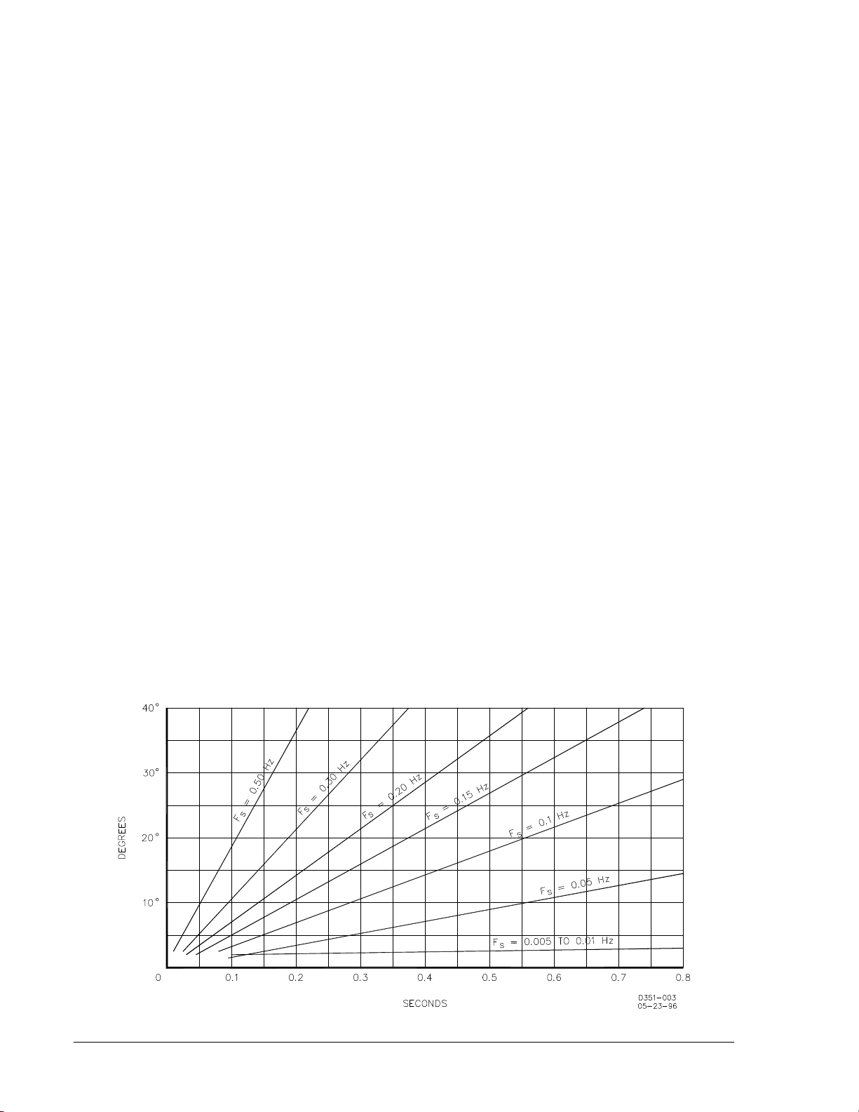
provide a basic description of slip frequency synchronization. The relationship between slip, advance
angle (or window), and breaker closing time is shown in Figure 1-1, and described by the formula:
= 360(+
)
where:
A
= advance angle in degrees. This is the time, measured in electrical degrees, between
A
initiation of breaker closure and the actual closure of the breaker contacts.
360 = degrees per slip cycle.
T
= the closing time of the circuit br eaker in secon ds. This is the t ime required fr om the c losure
CB
of the synchronizer output contact to the actual closing of t he circuit breaker contacts .
T
CB
is preset in synchronizer memory for each different break er controlled by the synchronizer .
EXCEPTION: In some applications ,
T
may re present the c haracteristic closing time of a
CB
group of breakers all having the same closing time.
T
= response time, in seconds, of the synchronizer breaker close output relay. (A non-
R
adjustable parameter approximately 0.008 second.)
F
= slip frequency in cy cles per second. This is the onc oming generator frequency minus the
S
bus frequency: positive for a generator speed higher than bus, negative for lower.
The relationships defined above should prove helpful in determining the settings for the autosynchronizer. Note that re ducing the advance angle (or window) also reduces the absolute v alue of the
slip frequency (which is the maximum permissible sp eed difference for which the mach ine is allowed to
close onto the bus). Lower slip frequenc ies are softer (i.e., les s liable to produce sy stem disturbance or
machine damage).
Higher frequencies, on the other hand, ar e quicker (i.e., allow sync hronizati on to be ac complis hed fas ter).
Again, these considerations should be balanced against others such as:
1. How fast do I need to be on line?
2. How critical is the machine?
3. How expensive is the machine as against possible outage (down) times?
A proper synchronizer application will take int o account the considerat ions mentioned above, as well as
others that may be unique to the system under consideration. See Figure 1-1.
Figure 1-1. Slip, Advance Angle, and Break er Closin g T ime
1-4 BE1-25A General Information 9146600990 Rev S
Page 15
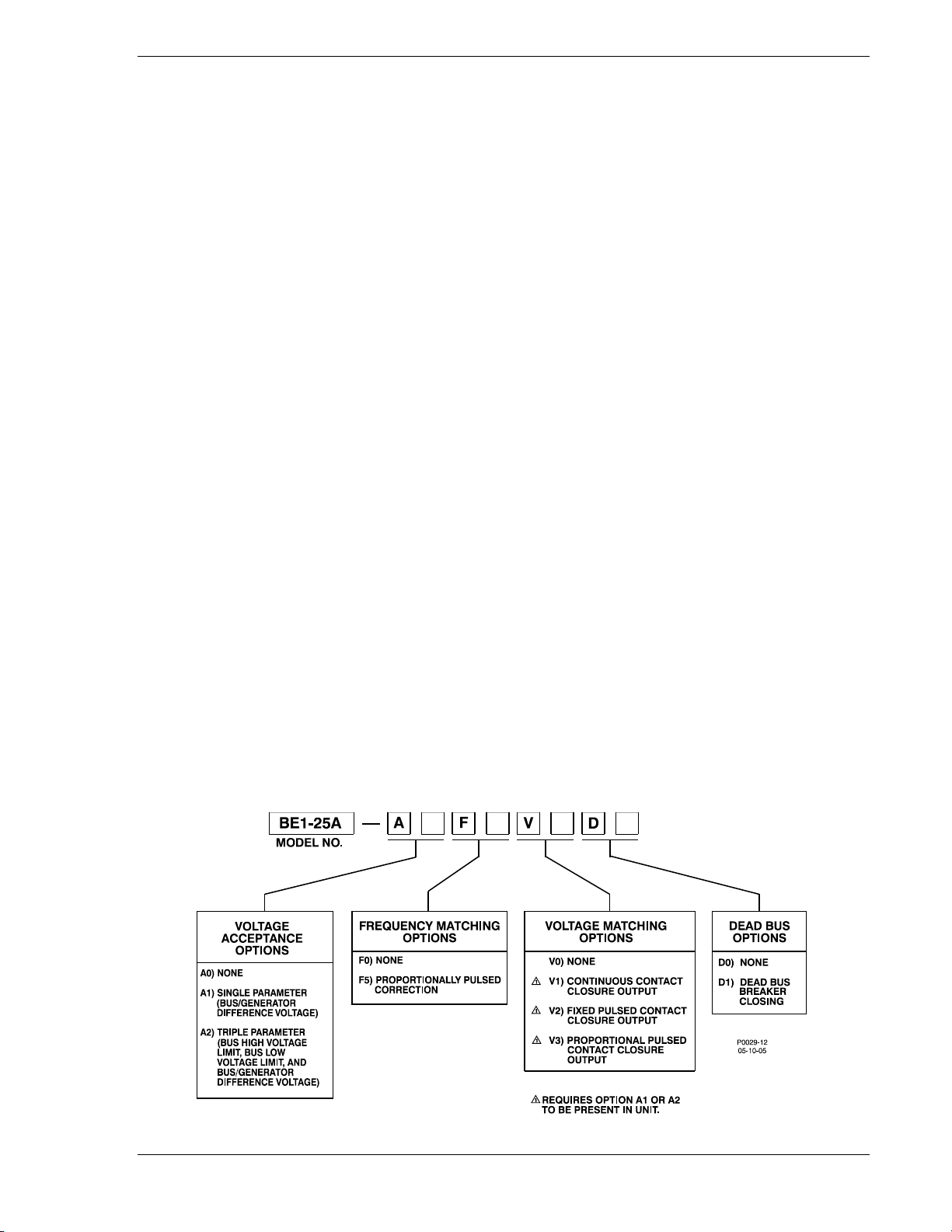
MODEL AND STYLE NUMBER
BE1-25A Auto-Synchronizer style numbers define the features of a specific device. Each pair of
characters within the style number is associated with a specific feature or option that m ay be selected
from the style chart on the following page.
For example, if the f irst two digits of the style number are A2, t he unit has the capab ility of deferring it s
closure command to the br eaker for any of the fo llowi ng reasons: (1) the bus is under a specif ied voltag e;
(2) the bus is over a spec ified volt age; and ( 3) the bus -to-genera tor voltage is less than a selecte d value.
Another consideratio n: If a voltage matching opt ion is desired (let assume it is), including one of the A
options is essential.
The second pair of digits determines the manner in which the Auto-Synchronizer commands the
generator to change s peed. This relay uses option F5, whic h can initiate two different types of sp eedchange commands: (1) pr oportional cor rection pulse s, that are issued w hen the slip freq uency is abov e
the allowable limit; and (2) target correction pulses, that automatically f orces synchronization when ever
an out-of-phase condition coincides with a near-zero slip rate.
The third pair of digits s elects the voltage matching c apabilities that are required for an application. We
might look first at the voltag e matc h ing m odu le w ith th e mos t features, V3. Let examine these capabilities,
and how they might be useful to a specific application.
Option V3 (like Option V2) can automatically initiate c orrective pulses to bring the generator voltage to
within the limits estab lished by O ption A1 or A 2. However, w hen the voltage differenc e between bus and
generator is less th an 20.0 volts, V3 has the a dditional capability of r educing the width of t he corrective
pulses by an amount proportional to the correction required. This feature can significantly reduce
overshoot where inert ia is particularly high (as in th e control of sluice gates). If this is beneficial to our
hypothetical application (let assume it is) then the matter is decided: the third pair of digits is V3.
Finally, we choose D1 as the last pair of digits because we want the capability of obtaining a closure
when a dead bus is det ected. ( D1 a lso has t he me ans of sett ing a thresh old vo ltage to define a de ad bus
condition.)
When ordering, it is recom mended that the s tyle nu mber be prec eded by th e mo del nu mber. Accor dingly ,
the style number now looks like (Figure 1-2):
BE1-25A A2 F5 V3 D1
where:
BE1-25A = the model number
A2 = 3-parameter voltage restraint
F5 = both proportional correction pulse and target pulse capability
V3 = proportional correction pulse capability
D1 = automatic closure capability upon recognition of a dead bus
Figure 1-2. Style Number Identification Chart
9146600990 Rev S BE1-25A General Information 1-5
Page 16

SPECIFICATIONS
General specifications for the BE1-25A system are provided in the following paragraphs. For
specifications that apply only to particular options, see the ensuin g subsection entitled Specificat ions of
Options.
Voltage Sensing Inputs 70 to 150 Vac, 50/60 Hz. Burden: Les s than 6 VA for the generator
(Bus and Generator) input; less than 2 VA for the bus input.
Contact Sensing Inputs Requires a user-supplied contact with a minimum rati ng of 0.05 A at
250 Vdc.
Power Supply Power for the internal circuitry may b e derived from 90 to 132 Vac at
50/60 Hz (single phase), o r 70 to 150 Vdc. B urden: Less than 20.0
VA.
Outputs Output contacts are rated as follows:
Breaker Closing
Normally open. Make and carry 30 A at 250 Vdc for 1 second, 7 A
continuously, and break 0.3 A at 250 Vdc. (L/R = 0.04).
Voltage, Frequency (Speed) Correction, and Lockout
Form C (SPDT). Make and break 5 A at 250 Vac (80% PF), 5 A at 28
Vdc (resistive), and 0.5 A at 120 Vdc (resistive).
Tolerances
Advance Angle The command for breaker closure occurs within ±3.0° of phase
coincidence of bus and generator. (Closure will not occur if the
calculated advance angle exceeds 40°.)
Lockout Occurs when breaker reopens within 15 ±10% seconds after the
initiation of breaker closure.
F
Slip Frequency (
) ±0.001 Hz
S
Generator Undervoltage ±1.0 V
Inhibit
Control Ranges The following parameters are settable over the indicated ranges.
MAX SLIP Adjustable from 0.01 to 0.500 in steps of 0.001.
BRKR TIME The characteristic breaker time settings are adjustable from 0.02 to
0.8 seconds.
NOTE
When a sync output closure is initiated, the sync output contact will be held
closed for the duration of the Breaker Operating Time setting (or 250 ms
minimum).
Generator Undervoltage Adjustable from 40 to 110 Vac.
Inhibit
1-6 BE1-25A General Information 9146600990 Rev S
Page 17

Generator Speed Adjustable between 0 to 99.9 seconds in 0.1 second increments.
Correction Pulses
Shock In standard tests, the relay withstood 15 G in each of three mutually
perpendicular axes without structural damage or degradation of
performance.
Vibration In standard tests the relay withstood 2 G in each of three mutually
perpendicular axes swep t o ver the r ange of 10 to 50 0 Hz for a total of
six sweeps, 15 minutes each sweep, without structural damage or
performance degradation.
Isolation 1,500 Vac at 60 Hz for one minute in accor dance wit h IEC 2 55-5 and
ANSI/IEEE C37.90-1978 (Dielectric Test).
Surge Withstand Capability Qualified to ANSI/IEEE C37.90.1-1989, Standard Surge Withstand
Capability Tests, and to IEC 255-5, Impulse Test and Dielectric Test.
Radio Frequency Interference Field tested using a five-watt, hand-held transceiver operating at
random frequencies centered around 144 MHZ and 440 MHZ, with
the antenna located six inches from the relay in both horizonta l and
vertical planes.
Maintains proper operation when tested for interference in
accordance with IEC C37.90-1989, Trial-Use Standard Withstand
Capability of Relay Sys tem s to Radiated Electromagn etic Int er ferenc e
from Transceivers.
Patent Patented in U.S., 1998, Patent No. 5761073.
UL Listed UL listed per Standard 508, UL File Number E97033.
C.S.A. Certification CSA certified per Standard CAN/C.S. A.-C22.2 Number 14.
CE Qualification This product meets or exceeds th e standards r equired for distribution
in the European community.
GOST-R Certification GOST-R certified per the relevant standards of Gosstandart of
Russia.
Temperature
Operating –40 to 70°C (–40 to 158°F)
Storage –65 to 100°C (–85 to 212°F)
Weight 16.0 lb (7.26 kg) net for basic synchr onizer (Includes the rac k frame,
MCU module, and power supply module.)
9146600990 Rev S BE1-25A General Information 1-7
Page 18

SPECIFICATIONS OF OPTIONS
To eliminate repetiti on, only the spec ifications that un iquely apply to a par ticular option are g iven below.
Specifications that are applicable throughout the unit (including the options) are stated above.
Voltage Acceptance Option A1
VOLTAGE DIFFERENCE CONTROL Minimum threshold adjustable from 0.5 to 5% of
generator voltage. (Generator voltage minus bus
voltage)
Weight 6.6 oz (186.0 g)
Voltage Acceptance Option A2
BUS VOLTAGE UPPER LIMIT CONTROL Maximum threshold adjusta ble from 100 t o 150 Vac.
BUS VOLTAGE LOWER LIMIT CONTROL Minimum threshold adjustable from 80 to 120 Vac.
VOLTAGE DIFFERENCE CONTROL Minimum threshold adjustable from 1 to 10 Vac of
generator voltage. (Generator voltage minus bus
voltage)
Weight 8 oz (226.8 kg)
Frequency Matching Option F5
CORRECTION PULSE WIDTH CONTROL Adjustable from 0 to 99.9 seconds.
CORRECTION PULSE INTERVAL CONTROL Adjustable from 0 to 99.9 seconds.
Weight 6.6 oz (186.0 g)
Voltage Matching Option V1
Weight 5 oz (140.6)
Voltage Matching Option V2
CORRECTION PULSE WIDTH CONTROL Adjustable from 0.1 to 5.0 seconds.
CORRECTION PULSE INTERVAL CONTROL Adjustable from 0.2 to 10.0 seconds.
Weight 7.0 oz (200.0 g)
Voltage Matching Option V3
CORRECTION PULSE WIDTH CONTROL Adjustable from 0.1 to 5.0 seconds.
CORRECTION PULSE INTERVAL CONTROL Adjustable from 0.2 to 10.0 seconds.
Weight 8.5 oz (240.4 g)
Dead Bus Option D1
VOLTS CONTROL Adjustable from 10.0 to 40.0 Vac.
Weight 6.6 oz (186.0 g)
1-8 BE1-25A General Information 9146600990 Rev S
Page 19

SECTION 2 • HUMAN-MACHINE INTERFA CE
TABLE OF CONTENTS
SECTION 2 • HUMAN-M ACHINE INTERF ACE ....................................................................................... 2-1
INTRODUCTION ................................................................................................................................... 2-1
ADDITIONAL MODULES ....................................................................................................................... 2-5
Voltage Acceptance Module A1 ......................................................................................................... 2-5
Voltage Acceptance Module A2 ......................................................................................................... 2-6
Frequency Matching Module F5 ......................................................................................................... 2-6
Voltage Matching Module V1 ........................................................................................................... 2-10
Voltage Matching Module V2 ........................................................................................................... 2-10
Voltage Matching Module V3 ........................................................................................................... 2-11
Dead Bus Module D1 ....................................................................................................................... 2-12
Figures
Figure 2-1. Location of Controls and Indicators ........................................................................................ 2-1
Figure 2-2. Test Module in Test Position ................................................................................................... 2-2
Figure 2-3. Proportional Corr ec tion Pulses ............................................................................................... 2-4
Figure 2-4. Module A1 ............................................................................................................................... 2-5
Figure 2-5. Module A2 ............................................................................................................................... 2-6
Figure 2-6. Module F5 ............................................................................................................................... 2-6
Figure 2-7. F3 Function Correction Pulse and Slip Frequency Relationship ............................................ 2-7
Figure 2-8. Proportional Relationship when GF>BF Switch is Open ........................................................ 2-8
Figure 2-9. Proportional Relationship when GF>BF Switch is Closed ...................................................... 2-9
Figure 2-10. Module V1 ........................................................................................................................... 2-10
Figure 2-11. Module V2 ........................................................................................................................... 2-10
Figure 2-12. Module V3 ........................................................................................................................... 2-11
Figure 2-13. Pulse Duration Timing for Option V3 .................................................................................. 2-11
Figure 2-14. Module D1 ........................................................................................................................... 2-12
9146600990 Rev S BE1-25A Human-Machine Interface i
Page 20

This page intentionally left blank .
ii BE1-25A Human-Machine Interface 9146600990 Rev S
Page 21
SECTION 2 • HUMAN-MACHINE INTERFACE
INTRODUCTION
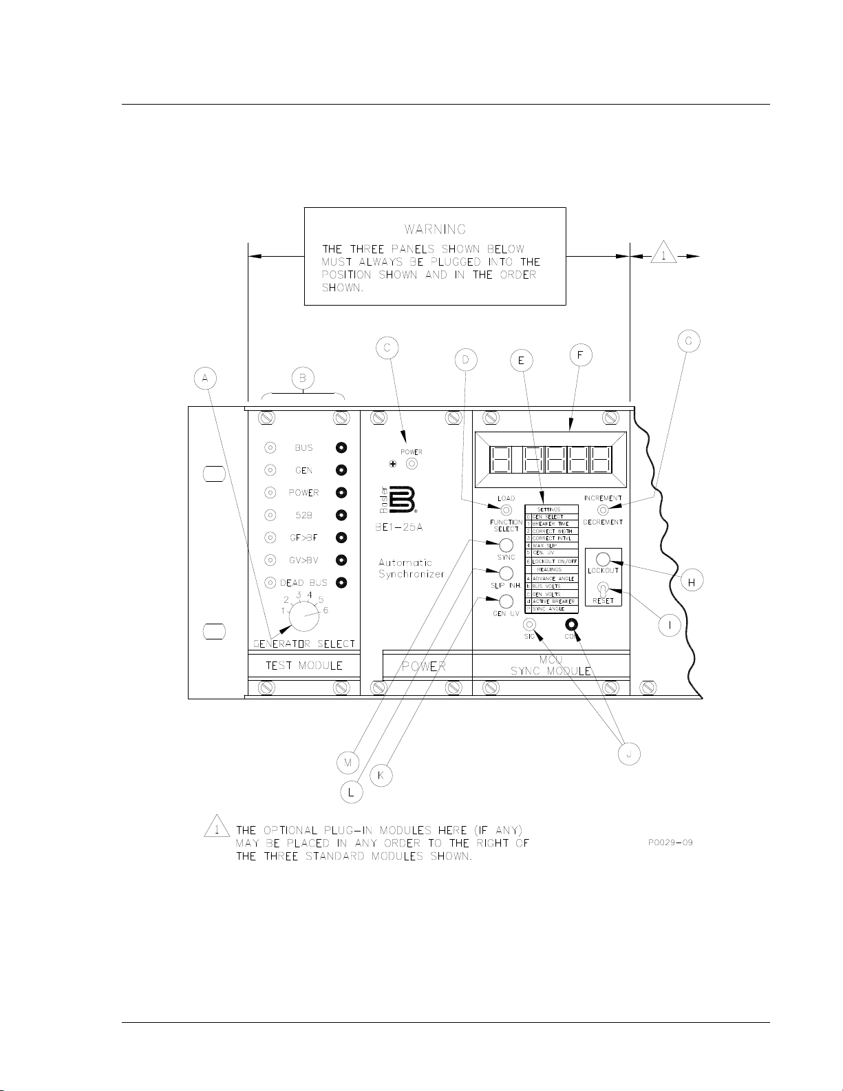
A basic BE1-25A Synchronizer (without options) is shown in Figure 2-1 and described in Table 2-1.
Figure 2-2 shows the Test Module in its offset position as required for testing. The remaining figures
describe the various options currently available.
Figure 2-1. Location of Controls and Indicators
9146600990 Rev S BE1-25A Human-Machine Interface 2-1
Page 22

Figure 2-2. Test Module in Test Position
Table 2-1. BE1-25A, Controls and Indicators (Refer to Figures 2-1 and 2-2)
Locator A - GENERATOR SEL ECT Control
When the Test Module is i n the tes t p os it ion (as s how n in Figure 2-2), this c ontro l s elect s one of t h e six
possible generator operation times that are stored in the memory of the MCU Sync module. This
selection process all ows the stored constant for a particular gen erator to be employ ed as a reference
for test purposes. This control has no function when the Test Module is in the operate position (as
shown in Figure 2-1.)
Locator B - Test Jacks
When the Test Module is in the test p osition (Figure 2-2), t he tip jac ks faci litate t esting in the follo wing
described manner. Wh en the Test Module is in the n ormal position (Figure 2-1), certain jacks s erve as
monitoring points as described in the following paragraphs.
Starting from the top, the seven pairs of jacks are:
1. BUS Voltage. When th e t est module is in t es t p os iti on , a simulated bus volta ge c an b e in jec ted
for test purposes. In normal position, monitors the bus voltage.
2. GEN (Generator) Voltage. When the test module is in the test position, allows a simulated
generator voltage to be injected for test purposes. In normal position, allows the generator
voltage to be monitored.
3. POWER. When th e test module is i n tes t position, allows the op er ati ng pow er t o be s u ppl ie d t o
the BE1-25A relay. In the normal p osition, allows the supp ly voltage from terminals 21 and 22
of TB1 to be monitored.
4. 52b. When the test module is in the test pos it ion, provides a means of simulatin g a 52b c ontac t
closure (by applyin g a jumper or closing a switch across thes e jacks). In the no rmal position,
allows the 52b contact input to be monitor ed. (Measur es approxi mately 10 0 Vdc when t he 52b
contact input is open, 0 Vdc otherwise.)
5. GF>BF. When the module is in the tes t position, provides the input term inals for a simulated
GF>BF contact closure. In the normal position, these jacks have no function.
2-2 BE1-25A Human-Machine Interface 9146600990 Rev S
Page 23
6. GV>BV. When the test module is in the test position, provides the input terminals for a
appears. The appropriate character appears until the INCREMENT/DECREMENT switch is
simulated GV>BV contact closure. In the normal position, these jacks have no function.
7. DEAD BUS. When the module is in the test position, provides the input terminals for a
simulated Dead Bus Enable signal. (This signal is useful only if the Dead Bus option is
present.) In the normal position, these jacks have no function.
Locator C - POWER LED
LED lights to indicate that the power supply is operating correctly.
Locator D - LOAD/FUNCTION SELECT Switch
A three-position switch with the following two active positions. (The switch is spring loaded to the
center position.)
FUNCTION SELECT. Each time the switc h is depres sed, it adv ances the displ ay (F) to s how the next
register (in the sequence listed in SETTINGS/READINGS chart (E)). The leftmost character of the
display may be found in the left c olumn of SETTINGS/READINGS chart wh ich describes the use o f
each register.
LOAD. Used to store data into memor y . To do s o, hold the s witc h in the raised position until the display
flashes (disappears and r eappears) (this takes approximately 1 second). The da ta showing in the four
rightmost digits of the display is now recorded in memory.
Locator E - SETTINGS/READINGS Chart
This chart lists various computer registers that control the sy nchronizer or monitor the system. Each
register is identified by the associated character in the left-hand column of the chart. This dig it also
appears as the left-m os t d i git of d is pl ay F w hen ev er th at register has been ac c ess ed by sw itc h D − i.e.,
the characters displayed in the righ tmos t d igi ts of the di splay repr es ent th e generator selected or status
of the particular register identified by the character in the left column of the chart.
The SETTINGS registers are:
0 (GEN SELECT). When f unction 0 is se lected, a — or a digit (1 through 6) appears as th e rightmost
character. After powering up or after reset, a — appears, but once a generator is selected, a digit
incremented. The I NCREMENT/DECR EMENT switch must be held for approximately one-half secon d
for the change to occur. The sequence is from — to 1 and incrementing to 6, and then wrapping
around to 1.
After a generator is sel ected an d t he FUN CTION SEL ECT sw itch is de press ed, t he dis play c hanges to
indicate the setting number (1 through 6) in the leftmost position and the constant (value) in the four
rightmost display characters. If a setting is changed, it must be loaded by operating the LOAD switch.
1 (BREAKER TIME). These registers ho ld the charac teristic op erating t imes of th e various bre akers in
the system. Numbers may be entered to represent break er operating time over the range of 0. 02 to
0.800 seconds.
2 (CORRECT WIDTH). The number in this regist er represents the raise and lower speed cor rection
pulse width. The pulse w idth is settable from 0 to 99.9 sec onds in 0.1 second increments. (Refer to
Figure 2-3.)
3 (CORRECT INTVL). The number in this register represents the raise and lower speed correction
pulse interval. The pu lse int er v al is s e ttab le from 0 to 99.9 seco nds i n 0 .1 sec o nd i nc r ements. (Refer to
Figure 2-3.)
9146600990 Rev S BE1-25A Human-Machine Interface 2-3
Page 24

Figure 2-3. Proportional Co rr ection Pulses
4 (MAX SLIP). The number in this register represents the maximum slip rate that is acceptable for
closure of any breaker t hat is under the supervision of the Sy nc Acceptor Relay. When the slip r ate
exceeds this setting, t he sy nc acc eptor clos ure out put is inhibite d. Th e maximu m slip limit is adjusta ble
over the range of 0.01 to 0.500 Hz in 0.001 Hz increments.
5 (GEN. UV). The number in th is register represents the m inimum voltage output that the generator
must have before an operator breaker closure attempt is enabled. This value is adjustable over the
range of 40 to 110 Vac in 1.0 volt increments . If the generator voltage is below this setting, voltage
correction pulses are inhibited.
6 (LOCKOUT ON/OFF). This regist er indicates whether or not the lockout feature is enabled. When
enabled, the BE1-25A rel ay will automatically enter L OCKOUT whenever the break er re-opens within
15 seconds after closure by the synchronizer. This prevents another clos ure of the breaker from this
source until LOCKOUT is terminated by (1) manually resetting the unit, using either the front panel
RESET control or an external (remote) contact; or (2) by removing, then reapplying power.
The READINGS registers are:
A (ADVANCE ANGLE). This r epresents the number of degr ees that the breaker closur e signal must
precede actual closure so t hat the latter will occur at, or c lose to, a phase difference of zero degr ees.
This compensation takes into consideration the operating speed of the breaker, as well as the armature
operation time of the outpu t relay. (This register perfo rms a monitoring function only. N o provision for
adjusting the data.)
b (BUS VOLTS). A d igital voltmeter with a range of 0 to 135 Vac th at reads the bus voltage. (This
register performs a monitoring function only. No provision for adjusting the data.)
C (GEN VOLTS). A digita l voltmeter with a range of 0 to 135 Vac that r eads the output v oltage of the
generator being addressed. (This register performs a monitoring function only. No provision for
adjusting the data.)
d (ACTIVE BREAKER). Displays an identifying digit (1 through 6) that represents the particular
breaker whose operating time, b-contact, closing circuit, and associated generator voltage is being
addressed by the BE1-25 A relay. (In some situations, this number can represent a group of breakers
having an identical operating time.)
P (SYNC ANGLE). This variable i ndicates the instantaneo us phase angle differenc e across the open
breaker. (This register performs a monitoring function only.)
Locator F - Five-Digit , 7-Segment Display
The leftmost digit indicates the functio n selected, while the remaining four digits indicat e the present
value held in memory for that function.
Locator G - INCREMENT/DECREMENT Switch
The constants and gen erator (SETTINGS) that may b e viewed in Display E (but not the R EADINGS,
such as bus voltage, etc.) may be a ltered in value by means of th is switch. When th e switch is ra ised
for approximately one-ha lf second and released, the number on the display is incremented. But wh en
held raised, the number o n the display is incremented repeatedly − at first slowly, then much f aster.
Similarly, when the s witch is depr essed, a decreme nt oc curs , and then rep eats sl owly, t hen fas ter − as
long as the switch is held down.
The switch is spring loaded to return to the center position from both directions.
Locator H - LOCKOUT LED
This LED lights to indicate t he occ urrenc e of a lock out c onditio n. During l ockout , the out put of the r elay
is inhibited from signaling the breaker to close. Lockout may be cleared by the front panel RESET
switch, by a (continued) remotely located contact, or by powering down and then powering up.
Locator I - RESET Switch
When momentarily raised, this switch restores the relay to operation after a lockout has occurred.
This switch is also used to return to the READING registers after changing settings.
Locator J - SIG (Signal)/COM (Common) Test Points
2-4 BE1-25A Human-Machine Interface 9146600990 Rev S
Page 25
Used to monitor the output breaker closure signal during testing or calibration.
Locator K - GEN UV (Generator Undervoltage) LED
An LED that lights when the generator voltage is below an acceptable range of the synchronizer. Under
this circumstance, the synchronizer is not allowed to close the breaker. (The acceptable range is
defined by the GEN UV setting of register 5.)
Locator L - SLIP INH LED
An LED that lights when the s lip frequency exceeds the para lleling tolerance establis hed by the MAX
SLIP setting. The breaker close output is inhibited whenever this LED is ON.
Locator M - SYNC LED
This LED is in parallel with the coil of the sync output relay. This LED will light (turn ON) during the time
that the sync output is energiz ed – i.e. only once each time the s ync conditi ons are met an d the output
is energized.
ADDITIONAL MODULES
Controls and indicators of the additional plug-in modules for the BE1-25A relay are described in the
following paragraphs.
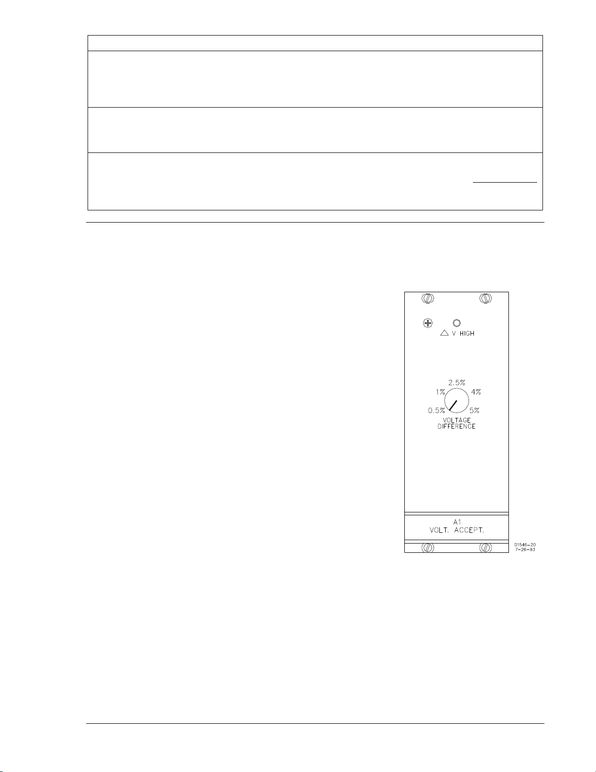
Voltage Acceptance Module A1
Option A1 introduces an a dditional enabling factor for the breaker
closing signal. This additional parameter, ∆V, represents the
difference in voltage o n the two sides of the circuit br eaker. I.e., if
∆V is greater than the setting established by the VOLTAGE
DIFFERENCE co nt ro l (Figure 2-4), the closure c o mm a nd out put o f
the BE1-25A unit is inhibited.
Note that the magnitude of the VOLT AGE DIFF EREN CE setti ng is
expressed as a percentage of the bus voltage: the voltage
difference (in %) = |∆V| * 100/V
An LED indicator, ∆V HIGH, illuminates when the voltage
difference exceeds the setting and the synchronizer is inhibited.
As will be seen later , this option or option A2 is a prerequisite of,
and a controller of, any Voltage Matching option that may be
present.
BUS
.
9146600990 Rev S BE1-25A Human-Machine Interface 2-5
Figure 2-4. Module A1
Page 26
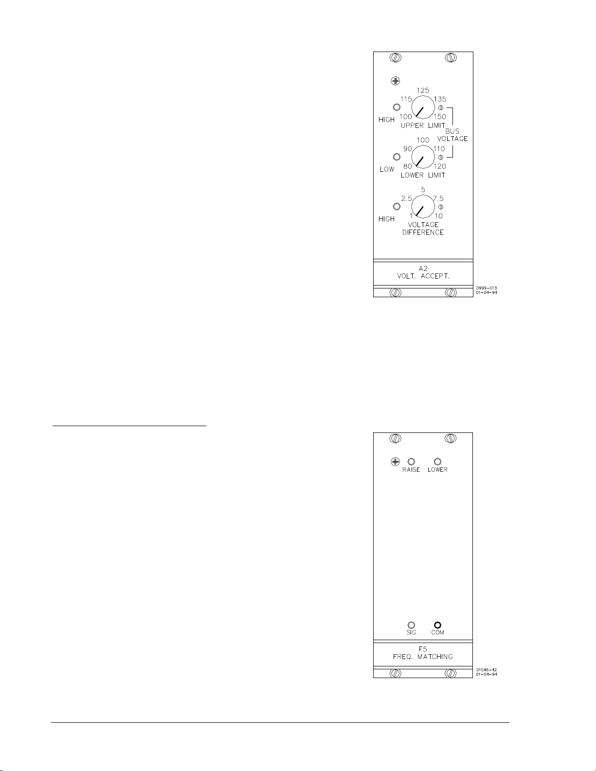
Voltage Acceptance Module A2
Voltage acceptance mo dule A2 can use as many as three voltage
parameters to add constraints to the issuance of breaker
command signals. This option or option A1 is a prerequisite of,
and a controller of, any voltage matching option that may be
present. Figure 2-5 illustrates the following descriptions.
1. The UPPER LIMIT control establishes a maximum bus
voltage. No closure is to be attempted when the bus
voltage is above the upper limit.
2. The LOWER LIMIT control establishes a minimum bus
voltage. No closure is to be attempted when the bus
voltage is below the lower limit.
3. The VOLTAGE DIFFERENCE control establishes the
maximum acceptabl e voltage difference between t he two
sides of the circuit breaker (generator voltage minus bus
voltage). No closure is to be attempted continuously
variable over the range of 1 to 10 Vac.
An LED to the left of each c ontrol lights whenever the associated
parameter is beyond the ra nge set by the control. As a result, the
breaker closure is inhibited.
Figure 2-5. Module A2
Frequency Matching Module F5
The F5 frequency matching module (Figure 2-6) provides a frequency-corrective (speed) signal that is
compatible with motor-oper ated m achi ne speed c ontro ls. Begin ning on A pril 30, 1 996, (BE1-25A, revis ion
R), the optional F5 frequency matching module includes the functionality of F1, F3, and F5 modes of
operation. The F1 mode of operation pr ovides fixed width puls es, fired pro portional to the slip fre quency.
The F3 mode of operation prov ides a continu ous correc tion signal unt il the measur ed slip is les s than the
slip setting. The F5 mode of operation issues correction pulse width proportional to the slip frequency.
F1 Function, Pulse Contact Closure
The F1 function generates a fixed-width correction pulse s ettable
from 0.1 to 99.9 seconds in 0.1 secon d increments . These pu lses,
though fixed in pulse width, are sent more often at higher slip
frequencies and less often as the slip decreases. In this (F5)
implementation, the fixed width pulse is fired proportional to the
slip frequency. The F1 function is implemented by setting the
correction pulse width to any non-zero value and setting the
correction pulse interval to zero. The F1 function provides a
continuous correction signal at high slip frequencies.
Approximately when the inverse of the slip frequency is greater
than the pulse width setting, the c ontinuous correction signal will
become a fixed-width correction pulse with a pulse interval
approximately equal to the inverse of the slip frequency.
Correction pulses are issued until the slip frequency is within 0.5 of
the slip setting. Sync closure can occur any time below the slip
setting if no correction pulses are being issued.
Figure 2-6. Module F5
2-6 BE1-25A Human-Machine Interface 9146600990 Rev S
Page 27
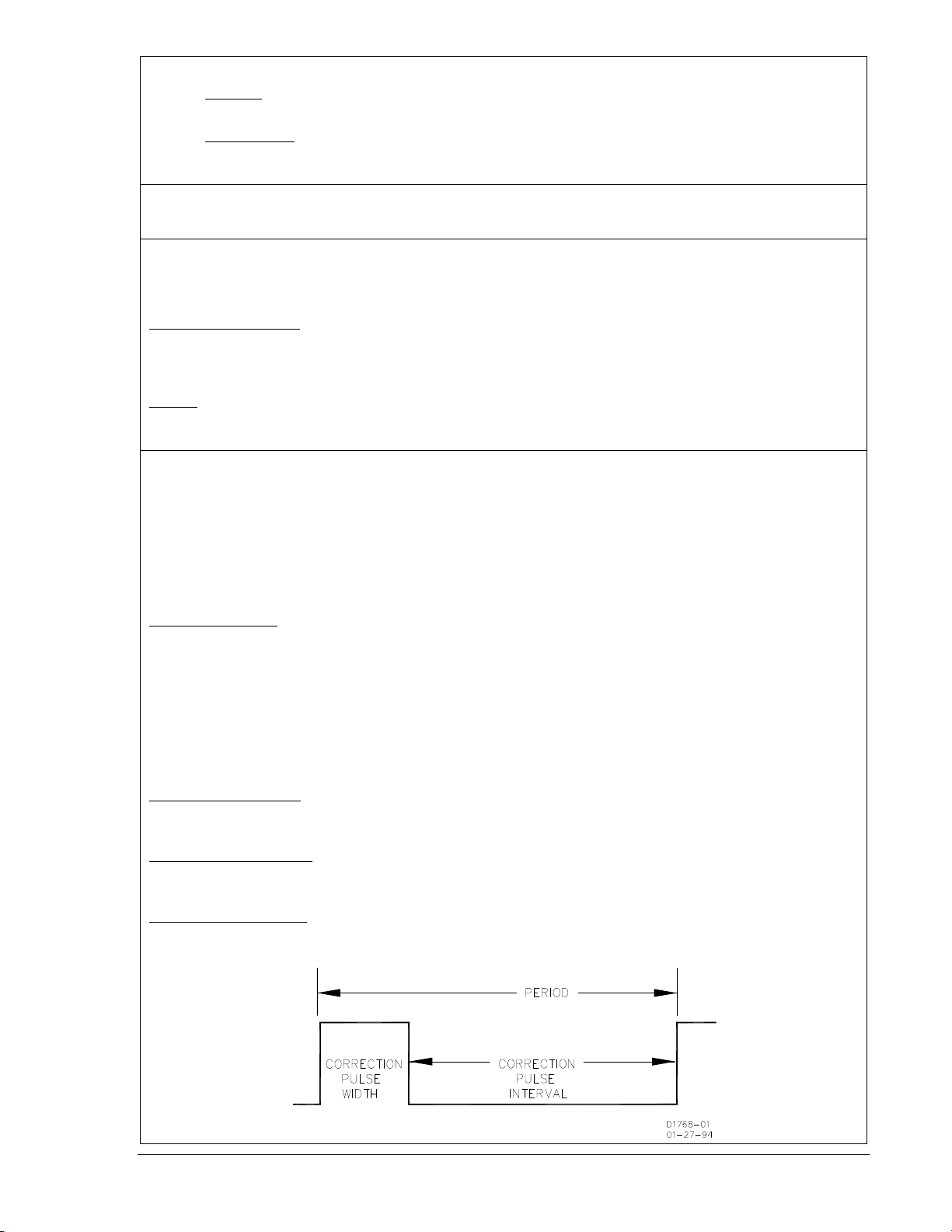
F3 Function, Continuous Correction Pulse
Correction
area
Correction
area
Neg
Slip
Pos
Slip
Max
Slip
Max
Slip
Slip =
0
GF > BF Sw
Open
Correction
area
Correction
area
Neg
Slip
Pos
Slip
Max
Slip
Max
Slip
Slip =
0
Correction Dead Zone
And
Synchronization Zone
Correction Dead Zone
And
Synchronization Zone
GF > BF Sw
Closed
D
2610-07
10-03-97
The F3 function provides a continuous correction signal until the measured slip is less than the slip
setting. The F3 funct ion is implemented by setti ng the correction pulse w idth to zero and the correc tion
pulse interval to zero or an y non-zero number . The correc tion pulse is continuo us (full-on) as long as the
slip frequency is greater t han the slip setting. No cor rections are issued if the s lip frequency is less than
the slip s etting. One exception would be t o bump the target pulse if the slip fre quency is very close to
zero. Figure 2-7 shows the F3 function correction pulse and slip frequency relationship.
Figure 2-7. F3 Function Correction Pulse and Slip Frequency Relationship
9146600990 Rev S BE1-25A Human-Machine Interface 2-7
Page 28

F5 Function, Proportional Frequency Correction
Max Slip
4 *
Max Slip 4 *
Max Slip
12.5%
25%
50%
2 *
Max Slip
100
%
50
%
25%
12
.5
%
Max Slip
2 *
Max Slip
Pos Slip
(GF>BF)
100%
Target Slip
Band
Min Slip &
Sync Range
Zero Slip
Correction Width
Setting Value
Correction Width
Setting Value
Percentage Correction
Pulse Width
Neg Slip
(GF<
BF)
Slip Inhibit LED On
Slip Inhibit LED On
Proportional Correction
Proportional Correction
1/2 Max Slip
1
/2 Max Slip
Frequency Correction Dead Band
Proportional Correction
Range
Proportional Correction
Range
D2610-08
10-03-97
A proportional correc tion pulse train is issued when the slip frequency is greate r than 50 percent of the
maximum slip frequency setting. The pulses are steered (as appropriate) to operate one of the two speedadjust output relays . The contacts of one relay are used to signal the ge nerator to r aise speed, w hile the
contacts of the other relay are used to signal the generator to lower its speed. The period of the correction
pulses is determine d by the settings loaded into the microprocessor. That is, the period is equal to the
sum of the correctio n p uls e int erv al plus the correction pulse w idth . T he period remains cons tan t o nc e th e
correction pulse width and correction pulse interval are set. The proportional correction pulse is
determined by the percent of correction required. If the slip frequency is greater than four times the
maximum slip allowed, the proportional c orrection pulse train is a t 100 percent of the sett ing (correction
pulse interval settin g plus correction pulse width sett ing). If the slip frequency is equal to the maximum
slip setting, the proportio nal correction pulse width is at 25 percent of the origina l setting. The correction
pulse interval (wait time) will increase t o maintain a consisten t correction pulse period (total of the pulse
interval and pulse width). Figure 2-8 shows the proportional relationship when the GF>BF switch is open.
Proportional correction is linear between 100 percent (four times maximum slip frequency setting) and
12.5 percent (equal to one-half maximum slip frequency setting). Synchronization is enabled at slip
frequencies less than the maximum slip setting. Although sync hronization is enabled at slip frequenc ies
below 50 percent of the maximum slip allowed, n o cor r ection pu ls es are is sued . T he pu ls es is s ued by t his
option (to direct the output relays ) may be monitored at the SIG and COM jack s. (+5 Vdc = raise pulse;
−5 Vdc = lower pulse.) Figure 2-9 shows the proportional relationship when the GF>BF switch is closed.
Figure 2-8. Proportional Relationship when GF>BF Switch is Open
2-8 BE1-25A Human-Machine Interface 9146600990 Rev S
Page 29

Figure 2-9. Proportional Relationship when GF>BF Switch is Closed
1/2 Max Slip
1/2 Max Slip
Max Slip
4 * Max Slip
12.5%
25%
50%
2 * Max Slip
100%
50%
25%
12.5%
Max Slip
Pos Slip
(GF>BF)
100%
Target Slip
Band
Min Slip &
Sync Range
Percentage Correction
Pulse Width
Neg Slip
(GF<BF)
Slip Inhibit LED On
Slip Inhibit LED On
Zero Slip
Correction Width
Setting Value
Frequency Correction
Dead Band
Proportional
Correction
Correction Width
Setting Value
Proportional Correction
3-1/2 * Max Slip
1-1/2 * Max Slip
D2610-05
10-06-97
Phase Correction
A target pulse is issued to the cor rection pulse train when the bus and generator are freque ncy matched
(within approximately six percent of the maximum slip setti ng) but not phase matched. The pulses are
steered to induce a s lip fre quency that may be a djusted to fall wit hin the all owable limits of th e correcti on
pulse train. The contacts of one r elay are used to signal the generat or to raise speed, while the cont acts
of the other relay are used to signal the generat or to lower its speed. The tar get pulses issued may be
monitored at the SIG and CO M jacks and are additional pulses to the correc tion pulse train. (+5 Vdc =
raise pulse; −5 Vdc = lower pulse .)
NOTE
If the generator voltage is less than the generator undervoltage setting,
correction pulses are inhibited.
9146600990 Rev S BE1-25A Human-Machine Interface 2-9
Page 30

Voltage Matching Module V1
Option V1 (Figure 2-10) issues a correc tive signal whose pur pose
is to increase or decrease the generator termi nal voltage to within
the voltage difference limit determined by the setting of the
Voltage Acceptance Optio n A1 or A2 (whichever is present). The
signal is in the form of a continuous closed-contact output.
Control and indicators are limited to:
a. RAISE LED, that lights when a raise voltage signal is
being output (at which time the raise output contact is
closed).
b. LOWER LED, that lights when a lower voltage signal is
being output (at which time the lower output contact is
closed).
Figure 2-10. Module V1
Voltage Matching Module V2
Option V2 (Figure 2-11), like opti on V1, issues corrective signals
that increase or decrease the generator voltage to within the
voltage difference limit determined by the setting of whichever
Voltage Acceptance o ption is present (A1 or A2). In the case of
this option, however, the c orrective signal is not c ontinuous (as in
V1), but rather is in the form of a pulsing output contact.
Pulse duration and interval are independently controlled by the
CORRECTION PULSE WIDTH control, and by th e CORRECTION
PULSE INTERVAL control.
When correction pulses are issued, the direction of the c orrection
is indicated by either the RAISE or the LOWER LED. This also
indicates which of the two output relays (and w hich set of output
contacts) is delivering the pulses: the raise output relay or the
lower output relay.
The pulses issued by this option (to direc t the output relays) may
be monitored at the SIG and COM jacks. (+12 Vdc = relay deenergized; 0 Vdc = relay energized.)
Figure 2-11. Module V2
2-10 BE1-25A Human-Machine Interface 9146600990 Rev S
Page 31

Voltage Matching Module V3
Option V3 (Figure 2-12) is similar to O ption V2, in that it initiates
corrective pulses that are used to increase or decrease the
generator voltage to within the voltage difference limit as
determined by the Voltage Acceptance mod ule (either A1 or A2).
Both V2 and V3 are functionally identical when the voltage
difference between genera tor and bus is equal to or greater than
20.0 Vac.
But when the voltage differ ence is less than 20.0 Vac, Option V3
differs in this respect: the duration of the corrective pulses no
longer follows in lockstep with the setting of the CORRECTION
PULSE WIDTH control. Instead, the duration of the corrective
pulses is reduced by an amount proportional to the correction
required (Figure 2-13). Note that the minimum pulse duration is
0.1 seconds.
The CORRECTION PULSE INTERVAL control determines the
period of the pulse train. (Unlike the PULSE WIDTH control, the
INTERVAL control does NOT vary from the set ting as a function
of voltage difference.)
The pulses issued by this option (to direct either the raise or the
lower output relay) may be monitor ed at the SIG and COM jacks.
(+12 Vdc = relay de-energized; 0 Vdc = relay energized.)
Figure 2-12. Module V3
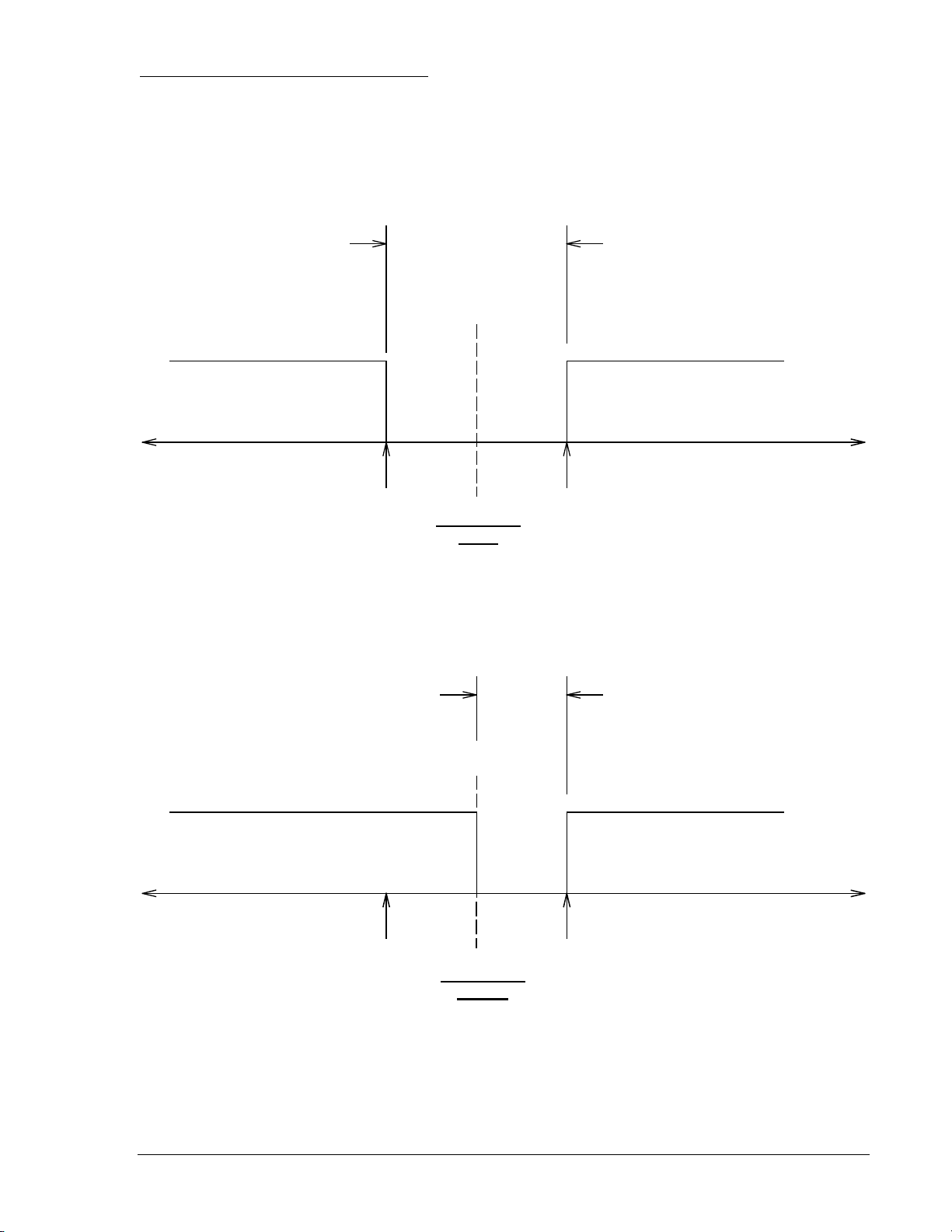
Figure 2-13. Pulse Duration Timing for Option V3
9146600990 Rev S BE1-25A Human-Machine Interface 2-11
Page 32

Dead Bus Module D1
When the external d ead bus c ontact is close d, module D1 ( Figure
2-14) determines when the bus is dead, and acts upon this
determination (if the br eaker is detected op en) by init iating a close
breaker signal. This signal is terminated as soon as the sync
acceptor recognizes the breaker as having closed, or when 100
milliseconds have passed (whichever occurs first).
The VOLTS control defi nes a dead b us condi tion by establ ishing a
voltage threshold between 10 and 40 Vac.
The DEAD BUS indicator i s an LED that lights whenever the bus
voltage is below the control setting.
Figure 2-14. Module D1
2-12 BE1-25A Human-Machine Interface 9146600990 Rev S
Page 33

SECTION 3 • FUNCTIONAL DES CRIPTION
TABLE OF CONTENTS
SECTION 3 • FUNCTIONAL DESCRIPTION ........................................................................................... 3-1
SYSTEM OPERATION .......................................................................................................................... 3-1
INPUT CIRCUITS .................................................................................................................................. 3-3
Contact Inputs .................................................................................................................................... 3-3
Front Panel Inputs .............................................................................................................................. 3-3
Analog Inputs ..................................................................................................................................... 3-3
MICROPROCESSOR CIRCUITRY ....................................................................................................... 3-3
OUTPUTS .............................................................................................................................................. 3-4
OPTIONS ............................................................................................................................................... 3-4
VOLTAGE ACCEPTANCE MODULE A1 .............................................................................................. 3-6
VOLTAGE ACCEPTANCE MODULE A2 .............................................................................................. 3-7
FREQUENCY MATCHING MODULE F5 .............................................................................................. 3-8
Frequency Correction ......................................................................................................................... 3-8
Phase Correction ................................................................................................................................ 3-8
VOLTAGE MATCHIN G M ODULE V1 .................................................................................................... 3-9
VOLTAGE MATCHIN G M ODULE V2 .................................................................................................. 3-10
VOLTAGE MATCHIN G M ODULE V3 .................................................................................................. 3-11
DEAD BUS MODULE D1 ..................................................................................................................... 3-12
Figures
Figure 3-1. System Block Diagram ............................................................................................................ 3-1
Figure 3-2. Auto-Synchronizer Block Diagram .......................................................................................... 3-2
Figure 3-3. Synchronizer Flow Diagram .................................................................................................... 3-5
Figure 3-4. Voltage Acceptance Module A1 Block Diagram ..................................................................... 3-6
Figure 3-5. Voltage Acceptance Module A2 Block Diagram ..................................................................... 3-7
Figure 3-6. Frequency Matching Module F5 Block Diagram ..................................................................... 3-8
Figure 3-7. Voltage Matching Module V1 Bl ock Diagram.......................................................................... 3-9
Figure 3-8. Voltage Matching Module V2 Block Diagram........................................................................ 3-10
Figure 3-9. Voltage Matching Module V3 Block Diagram........................................................................ 3-11
Figure 3-10. Dead Bus Module D1 Block Diagram ................................................................................. 3-12
9146600990 Rev S BE1-25A Functional Description i
Page 34

This page intentionally left blank .
ii BE1-25A Functional Description 9146600990 Rev S
Page 35

SECTION 3 • FUNCTIONAL DESCRIPTION
SYSTEM OPERATION
As the prime mover brings the oncoming gener ator up to speed, t he BE1-25A Au to-Synchronizer (Figure
3-1) compares the generat or output with the bus. When the m onitored frequency and phase angle (and,
optionally, the voltage) are within preset limits as described below, the BE1-25A Auto-Synchronizer
signals the controlled breaker to close.
Figure 3-1. System Block Diagram
To accomplish closur e qu ic k ly and with the least stress on th e sy s tem, a m ic ropr o c ess or in the MCU s y nc
module calculates (and thu s anticipa tes) the adv ance angle neces sary to compen sate for br eaker c losure
time, as well as for operation time of the output relay. To do so, it utilizes data stored in memory
concerning the characteristic closing times of the generator breaker to which it is connected.
As detailed in Section 4, the BE1-25A Auto-Synchronizer can be set-up to co ntrol multiple generators.
Each generator may be associated with a breaker whose closing time may b e different from the others .
The various closing times are stored in the synchronizer memory and called up according to which
generator/breaker combination the BE1-25A Auto-Synchronizer is connected. (The connecting is
performed by user-installed switches.)
After breaker closur e has been initiated, the Auto-Synchronizer is inhibited from fur ther operation for 15
±1.5 seconds.
9146600990 Rev S BE1-25A Functional Description 3-1
Page 36

A functional block diagram of the Auto-Sync hronizer is given in Figure 3-2, and is ref erred to in the circui t
descriptions that foll ow. A black box approach is tak en, with the emphasis on t he inputs and outputs to
the external world. Omitted from the diagram are the internal signals that communicate between the
various modules of t he system. Note that t he output relays show n in the lower right corn er of the figure
are not present unless the controlling options are installed.
Later in this section, additional functional diagrams are provided that describe the options.
Figure 3-2. Auto-Synchronizer Block Diagram
3-2 BE1-25A Functional Description 9146600990 Rev S
Page 37

INPUT CIRCUITS
Contact Inputs
At the upper left corner of Figure 3-2 are the contact sensing inputs. N ote that opto-isolator s protect the
internal circuits from the unwanted noise that is present on unconditioned lines. The inputs are:
• 52b - An input th at monitor s the 5 2b aux iliary c ontac t of th e contr olled breaker . (The 52b contac t,
when closed, indicates that the breaker is open.)
• Reset - An input that may be used to monitor a remotely located reset switch. (Not to be
confused with the RESET switch on the front panel of the unit.)
• GF>BF - An input that may be used to monitor a remotely located switch, that when closed,
enables the closure output of the Auto-Synchronizer if (and only if) t he generator frequency is
greater than the bus frequency. When this contact is open, closure is allowed from both
directions.
• 2, 3, 4, 5, 6 - Thes e five input contacts, in conjuncti on with the c ommon c ontact, p rovide a mea ns
of informing the Auto-Synchronizer which generator (and which generator breaker) has been
connected to the Auto-Synchronizer. A sixth generator /break er com bi nat ion ( gen e r ator/br eak er 1)
may be recognized by opening all five inputs, 2 throu gh 6. This is a d efault input tha t addresses
the first generator/breaker combination.
The various contact input signals are directed to input-conditioning circuitry, where they are translated into
binary notation and strobed into the microprocessor. Notice that power for the contact inputs is isolated by
means of a transformer supplied by the generator voltage sensing input.
At the lower left corner of Figure 3-2 are tw o inputs that go directly to optiona l modules. They are als o
translated into binary notation and strobed into the microprocessor. They are:
• GV>BV - If one of the volt age ac ceptanc e op tions is present, this input may be us ed to m on itor a
remotely located switch, t hat when cl osed, enab les the closur e output of the A uto-Synchronizer if
(and only if) the generator voltage is greater than the bus voltage. When this contact is open,
closure is allowed from both directions.
• Dead Bus Enable - If the dead bus enable option is installed, the clos ure of this contact input
coupled with a dead bus condition will bring about an immediate breaker close output.
Front Panel Inputs
Front panel inputs (Figure 3-2, abo ut one-third down at the left), represent (1) the LOAD & FU NCTION
switch, (2) the INCREMENT-DECREMENT switch, and (3) the LOCKOUT RESET switch of the MCU
sync module. Switches (1) and (2) control the d isplay and the memory of the Auto-Synchronizer. Switch
(3), when momentarily raised, restores the operation of the Auto-Synchronizer to the initialized condition.
Analog Inputs
Generator and bus volta ge inputs together mon itor both sides of the break er, and have a nominal rat ing
of 150 Vac at 50/6 0 Hz. Internal tra nsformers provide isolation and s caling. After the transformers, the
analog inputs enter squaring circuits. These circuits allow the phase information to be represented by
precise square waves nee ded to accurately determ ine the zero crossings . Additional circuitry pr ovides a
dc-analog representation of voltage magnitude for evaluation by the microprocessor and associated
circuits.
To conclude the inp ut description, a source of pow er for the digital circuits is r equired. Internal diod es
steer these voltages so tha t no polarity needs to be obs erved in makin g connect ions . These terminals will
accept either ac or dc, provided that it is within the voltage range of 70-150 V (and 50/60 Hz if ac).
MICROPROCESSOR CIRCUITRY
The microprocessor, with the as soci ated me mory a nd dec odin g log ic, perf orms a ll calc u lations, makes all
decision, and controls t he display and out put circuitry. Thes e functions are f or the most part, d etermined
by the software in the manner illustrated by the flow diagram of Figure 3-3.
Returning to Figure 3-2, a crystal os cillator provides a precise tim e reference for determining frequ ency
and phase relationships.
The power up/down r eset logic (at th e lower left corner) moni tors the intern al logic v oltages. If any of the
voltages fall below a critical threshold, the microprocessor is placed in a park mode. All decision making is
9146600990 Rev S BE1-25A Functional Description 3-3
Page 38

then inhibited until such time as all vital voltages return to normal. (Because all settings and vital,
programming instructions are held in non-volatile memory (EEPROM), and are not erased if power is
lost.)
Microprocessor operation is monitored by the watchdog circuitry. If some transient condition has disrupted
the normal pattern of o peration, the watchdog oper ates the alarm output, rese ts the microproces sor, and
initializes the program. The reset restarts the microprocessor. After the third such reset operation
(perhaps indicative of s ome hardware failure) , the microprocessor is stopped and shuts do wn the entire
unit. This condition remains until operating power is disconnected, then reapplied. (An inoperative
microprocessor usually appears as a display that is frozen and probably inappropriate or meaningless.)
OUTPUTS
Again referencing Figure 3-2, the Output Driv ers provi de the interfac e required between the logic circ uits
and the final outputs, which are the LED indicators and the output relays. The Breaker Close relay
provides a normally open contact. The other output relays are of the plug-in type, and are only
incorporated into the unit upon the addition of the relevant option(s). Note that these supplementary
relays provide both norma lly open and normally closed cont acts for each function represente d. (For the
terminal numbers of these contacts see Section 4, Installation.)
OPTIONS
The various options available for the BE1-25A Auto-Sy nchronizer Relay are described on the following
pages. Note that they are grouped into four categories: Voltage Acceptance, Voltage Matching,
Frequency Matching, and Dead Bus. Only one option from each category can be used at one time.
The basic Synchronizer m ay be upgraded to Automatic Sync hronizer status by incorporat ing one of the
voltage matching options and/or one of the frequency matching options. This may be accomplished at any
time − i.e., at original purchase or at any time thereafter.
Legend for Figure 3-3.
ADVANCE ANGLE - Number of degrees that the close breaker signal must precede
actual closure of the breaker so that the closure occurs at (or very
close to) zero degrees of phase difference
BF - Bus frequency
CLOSE BREAKER - Represent the closure of the BE1-25A output contact to provide
closing current to the breaker
DEAD BUS - A condition wher e the bus voltage is less than the s etting of module
D1, VOLTS control
GF - Generator fr equ enc y
GV - Generator voltage
MAX SLIP - Maximum slip frequency setting
F
UV - Undervoltage Setting
- Slip frequency
S
3-4 BE1-25A Functional Description 9146600990 Rev S
Page 39

Figure 3-3. Synchronizer Flow Diagram
9146600990 Rev S BE1-25A Functional Description 3-5
Page 40

VOLTAGE ACCEPTANCE MODULE A1
The sensed bus and generator voltages are rectified and output to the balance circuit. Any inequality
detected in the balanc e c ircuit re pres ents the v olt age differe nce ( )V) betw een the bus an d the g enera tor.
And the polarity of the difference represents the direction required for any corrective signal to the
generator.
The balance error signal (o r output) is am plified and di rected to the precision ful l wave rec tifier and to the
output gates. The output g ates provide a signal (utilized by any voltage ma tching module present) that
indicates the desir ed direction that any speed-corrective command should have. This takes the form of
either a raise signal or a lower signal, according to the polarity of the error.
A comparator monitors the VOLTAGE DIFFERENCE control. If the voltage difference betw een the two
sides of the breaker ()V) is found to be greater than the setting of the control, the breaker closure
command of the synchron izer is inhibited. (Th is infor mation is also used by any voltag e matching mo dule
in the system to determine whether corrective signals are required.)
Additional circuitry mon itors the external enable contact. The pres ence of a GV>BV signal (i.e., contact
closed) inhibits the sy nchronizer closure output un less the generator voltage is i ndeed greater than the
bus voltage. See Figure 3-4.
Figure 3-4. Voltage Acceptance Module A1 Block Diagram
3-6 BE1-25A Functional Description 9146600990 Rev S
Page 41

VOLTAGE ACCEPTANCE MODULE A2
Note: The first three paragraphs below repeat the material on the previous page.
The sensed bus and generator voltages are rectified and output to the balance circuit. Any inequality
detected in the balanc e c ircuit re pres ents the v olt age differe nce ( )V) betw een the bus an d the g enera tor.
And the polarity of the difference represents the direction required for any corrective signal to the
generator.
The balance error signal (o r output) is am plified and di rected to the precision ful l wave rec tifier and to the
output gates. The output g ates provide a signal (utilized by any voltage ma tching module present) that
indicates the desir ed direction that any speed-corrective command should have. This takes the form of
either a raise signal or a lower signal, according to the polarity of the error.
A comparator monitors the VOLTAGE DIFFERENCE control. If the voltage difference betw een the two
sides of the breaker ()V) is found to be greater than the setting of the control, the breaker closure
command of the synchron izer is inhibited. (Th is infor mation is also used by any voltag e matching mo dule
in the system to determine whether corrective signals are required.)
Module A2 differs from A1 by having additional comparators that monitor the UPPER LIMIT and the
LOWER LIMIT controls. Th e added c ircuitry serv es to inhibit op erat ion unless the bus voltage is less than
the upper limit, and greate r than the lower limit. Additional circuits mon itor the external enable contact.
The presence of a G V>BV signal (i .e., con tact close d) inh ibits the s ynchron izer clos ure output unless t he
generator voltage is indeed greater than the bus voltage. See Figure 3-5.
Figure 3-5. Voltage Acceptance Module A2 Block Diagram
9146600990 Rev S BE1-25A Functional Description 3-7
Page 42

FREQUENCY MATCHING MODULE F5
Frequency Correction
A proportional correc tion pulse train is issued when the slip frequency is greate r than 50 percent of the
maximum slip frequency setting. The pulses are steered (as appropriate) to operate one of the two speedadjust output relays . The contacts of one relay are used to signal the ge nerator to r aise speed, wh ile the
contacts of the other relay are used to signal the generator to lower the speed. The period of the
correction pulses is determined by the settings loaded into the microprocessor. That is, the period is equal
to the sum of the cor rection pulse interval plus the correction pulse width . The period remains c onstant
once the correction p ulse width and c orrection puls e interval are s et. The pro portional corr ection puls e is
determined by the percent of correction required. If the slip frequency is greater than four times the
maximum slip allowed, the proportional c orrection pulse train is a t 100 percent of the sett ing (correction
pulse interval settin g plus correction pulse width sett ing). If the slip frequency is equal to the maximum
slip setting, the proportio nal correction pulse width is at 25 percent of the origina l setting. The correction
pulse interval (wait time) will increase t o maintain a consisten t correction pulse period (total of the pulse
interval and pulse width).
Proportional correction is linear between 100 percent (four times maximum slip frequency setting) and
12.5 percent (equal to one-half maximum slip frequency setting). Synchronization is enabled at slip
frequencies less than the maximum slip setting. Although sync hronization is enabled at slip frequenc ies
below 50 percent of the maximum slip allowed, n o cor r ection pu ls es are is sued . T he pu ls es is s ued by t his
option (to direct the output relays) may be monitored at the SIG and COM j acks. (+5 Vdc = raise pulse;
−5 Vdc = lower pulse.)
Phase Correction
A target pulse is issued to the corr ection pulse train when the bus and generator are freque ncy matched
(within approximately six percent of the maximum slip setti ng) but not phase matched. The pulses are
steered to induce a s lip fre quency that may be a djusted to fall wit hin the a llowable li mits of the c orrecti on
pulse train. The contacts of one relay are us ed to signal the generator to r aise speed, while the contac ts
of the other relay are used to signal the genera tor to lower the speed. The target puls es issued may be
monitored at the SIG and CO M jacks and are additional pulses to the correc tion pulse train. (+5 Vdc =
raise pulse; −5 Vdc = lower pulse.) See Figure 3-6.
Figure 3-6. Frequency Matching Module F5 Block Diagram
3-8 BE1-25A Functional Description 9146600990 Rev S
Page 43

VOLTAGE MATCHING MODULE V1
Module V1 issues corr ective signals to the generator control system that caus e the voltage to approach
the voltage of the bus. The corrective output signal is in the form of a continuous contact closure.
This module is, in turn, controlled by whichever voltage acceptance module is in the system. (One of
these, either A1 or A2 must be present in order for module V1 to function.)
An inhibit signal fr om the A module, AINH, wi ll disable the V1 output (Figure 3-7). Additio nal A-module
signals, raise and lower, determine whether the output will raise or lower the generator voltage.
If the generator voltage is less than the generator undervoltage setting, voltage correction pulses are
inhibited. See Figure 3-7.
Figure 3-7. Voltage Matching Module V1 Block Diagra m
9146600990 Rev S BE1-25A Functional Description 3-9
Page 44

VOLTAGE MATCHING MODULE V2
Like the V1 module, m odule V2 issues corr ective signals to the generator contro l system that caus e the
generator voltage to ap proach the voltag e of the bus. In the case of th is module, howev er, the corr ective
signal is not contin uous , bu t r ath er a tr ain o f p ulses . The pulse width an d pulse frequency are ad jus ted by
front panel controls.
Module V2 (Figure 3-8) is controlled by whichever voltage acceptance module (A1 or A2) is in the system.
(Either A1 or A2 must be present in order for this module to function.)
An Inhibit signal from t he A module, AINH, will disab le the V2 output (Figure 3-8). Additional A-module
signals, raise and lower, determine whether the output will raise or lower the generator voltage.
If the generator voltage is less than the generator undervoltage setting, voltage correction pulses are
inhibited. See Figure 3-8.
Figure 3-8. Voltage Matching Module V2 Block Diagram
3-10 BE1-25A Functional Description 9146600990 Rev S
Page 45

VOLTAGE MATCHING MODULE V3
Like the V2 module, module V3 issues corrective signals in the form of p ulses to the generator control
system. The corrective s ignals are used to adjust the generator voltage toward the v oltage of the bus. In
fact, this module is function ally identical to module V2 so long as the voltage differ ence between the two
sides of the breaker is greater than 20.0 Vac.
However, when the voltage difference is less than 20.0 Vac, the duration of the corrective pulses is
proportionally reduced fr om the duration called for by the setting of the CORRECTION PULSE WIDTH
control. I.e., the dur ation falls of f by a ratio t hat is dire ctly proportion al to the red uced differ ence between
the two voltages.
A constant current gener ator ( Figure 3-9, bottom le ft) outp uts a cur rent that is used to char ge a c apacitor .
(The magnitude of the current is established by the CORRECTION PULSE WIDTH control.) The
comparator weighs the c apacitor rising charg e against the output of t he precision full wave r ectifier. The
interval pulse will then have the duration trimmed by an amount directly proportional to the capacitor
charge. This additional constraint is then input to the gate.
For other circuit features, refer to the functionally similar module V2 description on the previous page.
Module V3 is control led by whichever voltage ac ceptance modu le (A1 or A2) is in the sy stem. (Either A1
or A2 must be present in order for this module to function.) See Figure 3-9.
Figure 3-9. Voltage Matching Module V3 Block Diagram
9146600990 Rev S BE1-25A Functional Description 3-11
Page 46

DEAD BUS MODULE D1
Sensed bus voltage (up per left of Figure 3-10) is rectified, s caled to logic levels, and then presented to
the comparator. The co mparator determ ines whether or not t he bus is dead, as defined by the setti ng of
the VOLTS control. Not e that this control can define dead as any condition under a thr eshold setting in
the range of 10 to 40 volts.
If the bus voltage is les s than the VOLT S control set ting, the outpu t gate logic is enabled. At th is point, if
the output gate logic detects an enabling jumper (described below) and an undervoltage signal, the DEAD
BUS indicator is illumina ted and the 1-second timer is star ted. If, for the ensuing second, the 1-second
timer continues to receive a qualifying signal from the output gate logic (and a lockout state is not
evidenced), a DB (dead bus) signal is passed to the MCU sync module, that causes the MCU sync
module to generate a breaker close signal.
This module is enabled by an external contact closure in one of three ways:
1. By an external jumper across the terminals 9 and 10 of terminal strip TB1 (on the rear of the case).
2. By a manually-controlled external switch (same terminals).
3. By an automatically controlled enabling signal (same terminals).
See Figure 3-10.
Figure 3-10. Dead Bus Module D1 Block Diagram
3-12 BE1-25A Functional Description 9146600990 Rev S
Page 47

SECTION 4 • INSTALLATION
TABLE OF CONTENTS
SECTION 4 • INSTALLATION .................................................................................................................. 4-1
INTRODUCTION ................................................................................................................................... 4-1
RELAY OPERATING GUIDELINES AND PRECAUTIONS .................................................................. 4-1
MOUNTING............................................................................................................................................ 4-1
CONNECTIONS .................................................................................................................................... 4-3
General ............................................................................................................................................... 4-3
Multi-Generator Operation.................................................................................................................. 4-3
MAINTENANCE ..................................................................................................................................... 4-5
STORAGE.............................................................................................................................................. 4-5
Figures
Figure 4-1. Overall Dimensions ................................................................................................................. 4-2
Figure 4-2. Cutout Dimensions (for Non-Rack Mounting) ......................................................................... 4-3
Figure 4-3. Connection Diagram (Units Serial Number 546 and Higher) .................................................. 4-4
Figure 4-4. Controlling 6 Breakers with One BE1-25A .............................................................................. 4-5
9146600990 Rev S BE1-25A Installation i
Page 48

This page intentionally left blank .
ii BE1-25A Installation 9146600990 Rev S
Page 49

SECTION 4 • INSTALLATION
INTRODUCTION
BE1-25A relays are s hipped in sturdy cart ons to prevent damage during transit. Upon receipt of a re lay,
check the model an d style number a gainst the r equis ition and p acking l ist to s ee that they agree . Inspec t
the relay for shipping dama ge. If ther e is ev idenc e of d amage, f ile a cl aim wi th the carr ier, and not ify y our
sales representative or Basler Electric.
If the relay wi ll not be insta lled immed iately, s tore it in i ts original sh ipping car ton in a moistur e- and dustfree environment. Before placing the relay in service, it is recommended that the test procedures of
Section 5, Testing be performed.
RELAY OPERATING GUIDELINES AND PRECAUTIONS
Before installing or operating the relay, note the following guidelines and precautions.
When the unit is installed, the controls should be protected by the plastic cover supplied. This limits
access to the control settings.
NOTE
Be sure that the BE 1-25A is hard-wire d to earth ground w ith no smaller tha n 12
AWG copper wire attached to the ground terminal on t he rear of the case. When
the BE1-25A is config ured in a system with ot her devices, it is rec ommended to
use a separate lead to the ground bus from each device.
MOUNTING
BE1-25A Synchronizer s are designed to be rack-mounted. The ov erall dimensions are shown in Figure
4-1. Alternatively, the un it may be panel-m ounted, using the c utout dimensions of Figure 4-2 as a guide.
The unit may be mounted at any convenient angle.
9146600990 Rev S BE1-25A Installation 4-1
Page 50

Figure 4-1. Overall Dimensions
4-2 BE1-25A Installation 9146600990 Rev S
Page 51

Figure 4-2. Cutout Dimensions (for Non-Rack Mounting)
CONNECTIONS
General
Incorrect wiring may result in damage to the unit. Connections for Auto-Synchronizer terminals are
identified in Figure 4-3. Terminals are suitable for use with wir e sizes 14 AWG or lar ger.
When one BE1-25A unit is us ed to contro l more tha n one gen erator, r efer to Mult i-Generator Operation in
this section for a connection diagram.
Multi-Generator Operation
BE1-25A Auto-Sync hronizers can be used on mult iple-genera tor systems by s imultaneously switching all
relevant inputs and ou tputs from one generator to the next. Figure 4-4 is an interc onnect diagram for a
typical multiple-generator system controlled by one BE1-25A. This includes the generator sensing
voltage, the breaker 52b and closing coil circuits, and any leads associated with options (such as the
frequency and voltage matching lines to regulator or governor). Note that the closing time of each
generator breaker is entered into the memory of the BE1-25A, and is recalled by positioning the
SYNCHRONIZING SELECT SWITCH accordingly.
9146600990 Rev S BE1-25A Installation 4-3
Page 52

Figure 4-3. Connection Diagram (Units Serial Number 546 and Higher)
4-4 BE1-25A Installation 9146600990 Rev S
Page 53

Figure 4-4. Controlling 6 Breakers with One BE1-25A
MAINTENANCE
BE1-25A relays requir e no preventative m aintenance other than a period ic operational c heck. If the relay
fails to function properly, contact Technical Sales Support at Basler Electric to coordinate repairs.
STORAGE
This device contains long-life aluminum electro lytic c apac itors. For dev ices t hat a re not in serv ice (sp ares
in storage), the life o f these capacitors can be maximized by energ izing the device for 30 minutes once
per year.
9146600990 Rev S BE1-25A Installation 4-5
Page 54

This page intentionally left blank .
4-6 BE1-25A Installation 9146600990 Rev S
Page 55

SECTION 5 • TESTING
TABLE OF CONTENTS
SECTION 5 • TESTING ............................................................................................................................ 5-1
INTRODUCTION ................................................................................................................................... 5-1
OPERATING PRECAUTIONS ............................................................................................................... 5-1
DIELECTRIC TEST ............................................................................................................................... 5-1
APPLICATION ....................................................................................................................................... 5-1
General Information ............................................................................................................................ 5-1
Maximizing Auto-Synchronizer Performance ..................................................................................... 5-2
APPLICATION EXAMPLE ..................................................................................................................... 5-2
Example Parameters .......................................................................................................................... 5-2
Recommended Procedure ................................................................................................................. 5-2
VERIFICATION AND CALIBRATION .................................................................................................... 5-3
General ............................................................................................................................................... 5-3
Equipment Required ........................................................................................................................... 5-3
Preliminary Instructions ...................................................................................................................... 5-3
VERIFICATION TESTS ......................................................................................................................... 5-6
General ............................................................................................................................................... 5-6
Undervoltage (UV) Inhibit Verification Test ........................................................................................ 5-7
Slip Frequency Verification Tes t ........................................................................................................ 5-7
Sync Signal Verification Test ............................................................................................................. 5-7
Lockout and Reset Verification Test .................................................................................................. 5-8
Advance Angle Verification Tes t ........................................................................................................ 5-8
VERIFICATION TESTING OPTIONS .................................................................................................... 5-9
General ............................................................................................................................................... 5-9
Voltage Acceptance Module A1 Verification Test .............................................................................. 5-9
Voltage Acceptance Module A2 Verification Test ............................................................................ 5-10
Frequency Matching Module F5 Verification Test ............................................................................ 5-10
Voltage Matching Module V1 Verification Test ................................................................................ 5-11
Voltage Matching Module V2 Verification Test ................................................................................ 5-11
Voltage Matching Module V3 Verification Test ................................................................................ 5-11
Dead Bus Module D1 Verification Test ............................................................................................ 5-12
Figures
Figure 5-1. Bench Test Setup .................................................................................................................... 5-4
Figure 5-2. Test Setup for Installed Unit .................................................................................................... 5-5
Figure 5-3. Option V2 Waveform ............................................................................................................. 5-11
Tables
Table 5-1. Advance Angle Test Parameters (Maximum slip rate must be set at 0.5000 Hz.) .................. 5-9
9146600990 Rev S BE1-25A Testing i
Page 56

This page intentionally left blank .
ii BE1-25A Testing 9146600990 Rev S
Page 57

SECTION 5 • TESTING
INTRODUCTION
BE1-25A Auto-Synchronizers are calibrated and tested for correct operation at the factory and all
calibration pots are sealed. Immediately upon receipt of the relay, or after extended service, it is
recommended that the VERIFICATION T ESTS in this sec tion be performed. The se comprehensive tes ts
verify all operating parameters.
OPERATING PRECAUTIONS
Before operation, note the following precautions.
• Always be sure that extern al operatin g (mon itored) co nditions are stab le befor e removi ng a BE1-
25A unit from service.
• The BE1-25A is a solid-state device and has been type tested in accordance with the
requirements defined below under Dielectric Test. If a wiring insulation test is required on the
switchgear or panel assembly of which this unit is a part, see Dielectric Test below.
• Be sure that the BE1-25A c ase is hard wired to earth ground using th e ground terminal (A1) on
the rear of the unit.
• When the unit is in service , the controls should be protected by th e plastic cover supplied. This
limits access to the control settings.
DIELECTRIC TEST
In accordance with IEC 255 -5 and ANSI/IEEE C37.90-1978 , one-minute dielectric (high pot ent ial) tes ts up
to 1500 Vac (45-65 hertz) may be performed. Note that:
• Decoupling capacitors are employed from all termin als to ground. Accordi ngly, a leakage current
of approximately 20 milliamperes is to be expected when high potting at 1500 Vac, 60 hertz.
• Varistors are connected across all terminal-pairs of terminal strip TB1, and across terminals 21/22
of TB2. Do NOT high pot from terminal to terminal across these varistors. Normal high pot
procedures (high potting from terminal to frame) are not affected by these varistors.
• A one megohm resistor is u sed in t he cont act sens ing i nput circu it betw een th e minus s upply a nd
the chassis. High pot ential testing on these contact sensin g inputs (TB1, termi nals 3, 4, 5, 6, 9,
10, 11, 12, 13, 14, 15, and 16), (TB2, terminals 21 and 22) m ay da mag e the internal resistor . Us e
a high resistance tester (megger) or alternate means to test these contacts.
APPLICATION
General Information
Although operation of BE1-25A Auto-Synchronizers is straightforward, the following suggestions are
offered.
• When using the LOAD switch, there is a built-in delay before the display responds to the
command. This delay is for the purpose of security — so that a deliberate ac tion is required to
effect a change, not an accidental bump. (If the switch is released before display
acknowledgment, the original setting is retained.)
• Dashes in the display indicate an open input or out-of-range condition.
• When power is first ap plied to the unit, the display defaults to Function P, at which position the
display functions as a digital synchroscope. This default also occurs whenever the unit is RESET.
• In an ideal system, a smo other c losing res ults when th e generator speed a nd voltage ar e exactly
in synchronism with the sy stem. Depending on the system, this usu ally is not possible. Closing
from the high side with GF > BF usually results in less str ess on system components. Contact
sensing inputs can be set so that the synchronizer only allows closing when GF > BF and/or GV >
BV.
9146600990 Rev S BE1-25A Testing 5-1
Page 58

• Setting MAX SLIP to o low can result in ex cessive hunting by the governor. A l ow inertia system
driven by an internal comb ustion pr ime mover is es pecially prone to this, since the power s trokes
can (prior to breaker closure) mod ulate the fun damental freque ncy of the gener ator outp ut. If the
resulting sidebands (or jitt er) exc eed the MA X SLIP freque ncy, overs hoot and prolonge d delay in
reclosing will likely occur.
• Because installations may have different characteristics, there is no standard value for the
generator speed correction pulse width and interval settings. Refer to the following paragraph
Maximizing Auto-Synchr onizer Perfor mance for a reco mmended proce dure to ac hieve values for
the generator speed correction pulse width and interval settings.
• Whenever the LOAD switch is raised, the BE1-25A becomes inactive (non-functional) for 1.0
second.
Maximizing Auto-Synchronizer Performance
Disconnect the breaker from the Auto-Synchronizer output. Select a pulse width and interval setting
based on governor sens itivi ty. Rec ord the sy nchron izin g time ( that ti me fro m when the Auto-Synchronizer
initiates correction pulses to when the Auto-Synchronizer issues the breaker close signal).
If excessive overshooting occurs, reduce the correction pulse width and increase the correction pulse
interval. If the gener ator sp eed increas es too sl owly, t hen increas e the c orrection puls e width and reduc e
the correction pulse interval.
Maximum performance is achieved if sy nchronization oc curs within one to tw o minutes provi ding that the
Auto-Synchronizer takes control of the generator within a two hertz slip frequency window.
APPLICATION EXAMPLE
Example Parameters
• A generator breaker whose characteristic closing time is 385 milliseconds.
• A maximum allowable slip rate of 0.1 hertz. (This slip rate suggests that our hypothetical
generator is of greater than average size.)
• A generator undervolta ge of 65 Vac. (I.e., at this volt age or b elow, no effor t shall be made by the
Auto-Synchronizer to control the generator voltage.)
• For this example, the gen erator is designat ed West. This gener ator breaker closi ng time is to be
stored as generator breaker 2 in the Auto-Synchronizer memory.
Recommended Procedure
Step 1. Bring the me mory register f or the test generator int o view by depressing th e FUNCTION s witch
once (MCU disp lay should show 0 in the left-most d igit and—in the right-most dig it), and then
depress the increment swit ch twice to select generator br eaker 2 (MCU display shows 2 in the
right-most digit).
Step 2. Depress the FUNCTION switch once and observe that the display left-most digit shows 1.
Change the display to r ead 1.38 5, the .385 represents the new breaker-closing t i me in sec onds.
This is done by h old in g a nd /or stepping the INCREM E NT /DECR EM ENT switch until th e des ire d
number is displayed. (Note the two-speed response as the switch is held depressed. This
feature greatly speeds up the selec tion proces s.) Raise the LOAD switch , and hold it raised for
at least two seconds. The display will blank out and then, after about one second, will read
1.385. This is to acknowl edge that the characteristic closing t ime for the breaker that controls
the West generator has been recorded.
Step 3. Depres s the FUNCTION s witch once and observe that the d isplay left-most digit shows 2. Use
the INCREMENT/DECR EMENT switch to select a value/sett ing for the correction pulse width.
Raise the LOAD switch, a nd hol d it rais ed for abou t tw o seconds . The d isplay will blank out an d
then return, indicating that the new correction pulse width has been stored in MCU memory.
Step 4. Depress the FUNCTION s witch once and observe that the d isplay left-most digit shows 3. Us e
the INCREMENT/DEC REM ENT switc h to s elect a v alu e/setti ng for the c orrec tion pulse int erval.
Raise the LOAD switch, a nd hol d it rais ed for abou t tw o seconds . The d isplay w ill bla nk out an d
then return, indicating that the new correction pulse interval has been stored in MCU memory.
5-2 BE1-25A Testing 9146600990 Rev S
Page 59

Step 5. Depress the FUNCTION SELECT switch twic e to cause the f igure 4 to app ear as the left-most
digit of the display. As indicated on the front panel chart, this is the register that stores the
maximum slip rate. Using the INCREMENT/DECREMENT switch, adjust the display digits to
read .100, then rais e the LO AD swit ch and hold it r aised f or ab out two sec onds until th e dis play
goes from blank to 4.100. The maximum slip rate is now loaded.
Step 6. Step th e display to the nex t register which is 5 (G ENerator UnderVoltag e). Enter and load 65,
using the previous procedures.
CAUTION
Before placing the Auto-Synchronizer into service, be sure that the LOCKOUT
ON/OFF register (6) is set to system requirements. When OFF, the AutoSynchronizer is free to repeatedly close the breaker into a fault.
Step 7. To chan ge the LOCKOUT condition (i. e., from ON to OFF to ON, etc. ): Select function 6 and
raise the LOAD switch for approximately two seconds. The disp lay will toggle to the opposite
condition that it held. (Lon stands for lockout ON, Lof for lockout OFF.)
The setup procedure is c ompl ete. If y ou wis h to place the rel ay into s ervic e, you can park the disp lay at a
parameter that you wish to monitor, such as ADVANCE ANGLE or BUS VOLTS.
NOTE
Operate the Reset lever to return to the READING registers after changing
settings.
VERIFICATION AND CALIBRATION
General
This paragraph is an introduction to the specific ver ification and calibration proc edures given lat er in this
section.
Equipment Required
• Two dynamic frequency sources calibrated to 1.0% accuracy
• One oscilloscope
• One digital voltmeter
• One counter
• One stopwatch
• One phase angle meter
Preliminary Instructions
The various verification tests may be done independently. However, certain assumptions and blanket
instructions apply as given in the steps that follow.
CAUTION
The BE1-25A Auto-Synchronizer can be tested before installation using the
bench-test setup shown in Figure 5-1.
9146600990 Rev S BE1-25A Testing 5-3
Page 60

Figure 5-1. Bench Test Setup
CAUTION
After installation, it is inconv enient to remove the many connec tions on the bac k
of the unit. For this reason, spec ial provisions for tes ting have been incorp orated
that require the following procedures of steps 1 through 5.
5-4 BE1-25A Testing 9146600990 Rev S
Page 61

Step 1. Loosen th e (4) screws that secure the test module and ex tract it from the case. This removes
external electrical connections at TB1 of the BE1-25A.
Step 2. Note that two sets of tr acks hav e been provi ded for th e test module. Carefully enter the modu le
into the right-hand track s (upper and lower), and gent ly push the module forward. (If a bind or
obstruction is felt, pull the module back slightly and check that it is properly entered into the
right-hand pair of tracks.) Figure 5-2 shows the module fully entered into the offset—or test
mode—position.
WARNING!
Do NOT apply Test power to tip-p lugs until they are ins erted into the test m odule
POWER jacks.
Step 3. Apply operating power to the BE1-25A through the POWER jacks of the test module. The power
supply module POWER LED should be ON to indicate that the BE1-25A unit is functioning.
Figure 5-2. Test Setup for Installed Unit
9146600990 Rev S BE1-25A Testing 5-5
Page 62

Step 4. With the sens ing connections to the BE1-2 5A (via the rear case terminals) now disconnected,
all inputs for testing must be supplied by the jacks of the test module. At this time the jacks have
the following functions (functions are illustrated in Figure 5-2).
• BUS - Apply simulated bus voltage here.
• GEN - Apply simulated generator voltage here.
• POWER - These jacks are used to supply operating power. (Reference step 4.)
• 52b - Plug in a normally closed momentary pushbutton switch into these jacks to
simulate a 52b signal from the auxiliary contact of the breaker.
• GF>BF - Short these jacks together to simulate the closing of the GF>BF contact
sensing input terminals 13 & 14 of TB1 (reference Figure 5-2). When shorted, the
BE1-25A will not issue a breaker closure signal unless the generator frequency is
greater than the bus frequency.
• GV>BV - (Only used when an A option is installed.) Short these jacks together to
simulate the closing of the GV>BV contact sensing input terminals 11 & 12 of B1
(reference Figure 5-2). When s horted, the BE1-25A will not iss ue a breaker closure
signal unless the generator voltage is greater than the bus voltage.
• DEAD BUS - (Only used when a D option is installed.) Short these jacks together to
simulate the closing of t he dead bus c ontac t input t erminals 9 & 10 of TB1 (r efer ence
Figure 5-2). When shorted—AND if the dead bus opt ion is incorporated—the BE125A will issue a breaker-closure signal when the bus voltage drops below the set
threshold that defines a dead bus.
Step 5. Monitor the outputs as follows:
With test module in the test position—Operation of the Br eaker Closure (i.e., SYNC) relay
may be monitored at the SIG & COM jack s of the MCU sync module, usin g an oscilloscop e, as
illustrated in Figure 5-2. Each time the SYNC LED turns ON, the SIG voltage should be th e
same as the COM jack voltage. At all other times th ere should be 12 Vdc betw een these jacks
(with SIG +). (Note that this monitoring procedure only confirms that an operating voltage is
being extended to the output relay. It does not confirm a contact closure by this relay.)
NOTE
When the test module is in test position, all output relays are de-energized.
For bench testing (with test module in normal operating position)—If any of the plug-in
(option) relays are present , the pull-in of the relay armature(s ) may be observ ed by open ing the
hinged door at the rear of the unit.
Sync output—For many test purposes, the most conveni ent monitor of the sync output is the
SYNC LED. (Lit when sync relay is closed.) However, the bench test setup of Figure 5-1 has the
advantage of verifying the sync output plug-in relay is working properly.
VERIFICATION TESTS
General
Five test procedures cover the three basic modules (MCU sync module, test module, and power s upply).
Testing of the optional modules is covered in individual verification tests. The five test procedures are:
• Undervoltage (UV) Inhibit Verification Test
• Slip Frequency Verification Tes t
• Sync Signal Verification Test
• Lockout and Reset Verification Test
• Advance Angle Verification T est
5-6 BE1-25A Testing 9146600990 Rev S
Page 63

NOTE
Verification test procedures for Auto-Synchronizers prior to serial number 300,
and for discontinued Options B3, B5, F1, F2, F3, F4, and V4, are given in Section
7.
All option modules should NOT be installed when performing the basic
verification tests because they affect the basic unit effective parameters.
Undervoltage (UV) Inhibit Verification Test
Step 1. For a benc h test, connect the unit as in Figure 5-1. Otherwise c onnect the unit as described
previously in steps 1 throu gh 4, and illustrated in Figure 5-1. Leave GF>BF, GV>BV, a nd dead
bus open (i.e., OFF) at this time. Set the s imulated bu s and generator volt ages at 120 Vac, 60
hertz.
Step 2. Set the GEN UV register to 40 V ac. Reduce the sim ulated generator volta ge until the GEN UV
LED turns ON. This s hould occur as the simu lated generator vo ltage goes below 40 ±1.5 Vac .
(Beginning here, the word simulated shall be understood without repeating it.)
Step 3. Return the GEN UV register to 110 Vac : the GEN UV LED should rema in ON. Increase the
generator input voltage until the GEN UV LED turns OFF. This should occur as the input voltage
rises above 110 ±1.5 Vac .
NOTE
If there is a slip r ate, the SYNC LED will b egin flash ing (inste ad of extinguis hing)
as synchronization is detected.
Slip Frequency Verification Test
Step 4. Set the GEN UV register to 40 Vac. Set the MAX SLIP register for 0.500 hertz.
Step 5. Adjust the bus input and the generator input to 120 Vac at 60.00 hertz.
Step 6. Slowly adj ust the generator input frequency lower. At 59.49 ±0.01 her tz, the SLIP HIGH LED
should turn ON. Slowly move the generator frequency above and below the threshold and
observe that the LED acknowledges the slip frequency status within the stated tolerance.
Sync Signal Verification Test
Step 7. With th e b us input at 120 Vac, 60.00 her tz , a djust the generator input to 120 Vac at 59 .90 her tz .
Set MAX SLI P (the # 4 reg ist er) for 0.2 50 hertz. Ro tat e the GEN ER ATOR S ELE CT contr ol knob
to the generator position of choice. Set the register of the active breaker to 0.40 seconds.
NOTE
Always load in all new breaker timer settings, and always verify the active
breaker by momentar ily selecting item d from th e MCU read ings menu. ( Breaker
settings, unlike other settings, must be loaded before they can take effect.)
When a sync output closure is initiated, the sync output contact will be held
closed for the duration of the Breaker Operating Time setting (or 250 ms
minimum).
Step 8. Using an extern al sync hroscope, c heck that the SYNC LED turns O N at 14 ±3°, and O FF at 0°.
The breaker closure outp ut (as monitored by a lamp (Figure 5-1), or an oscilloscope (Figure
5-1)) should follow the SYNC LED.
Step 9. Install a jumper at the GF>BF jacks of the test module. The SYNC LED should immediately stop
flashing. Remove jum per to bring back the flashing SYNC L ED. (The flash ing is caused by t he
slip r ate. Note that (with this jumper ap plied) the gene rator frequenc y must be greater than that
of the bus for a sync output to be initiated.)
9146600990 Rev S BE1-25A Testing 5-7
Page 64

Step 10. Return the display to MAX SLIP (t he #4 setting). Use the DECREMENT switch to r educe the
setting fr om the initial (0. 250) value to 0. 090. Use the LOAD switch to s ave the new M AX SLIP
setting into memory. Raise the LOCKOUT RESET switch: the SYNC LED should cease
flashing and the SLIP HIGH LED should turn ON.
Step 11. Return the MAX SLIP s etting to 0.250 and use the L OAD switch to save th e new MAX SLIP
setting into mem ory. The SYNC LED should res ume flashing and the SLI P HIGH LED should
turn OFF.
Step 12. Vary the bus and generat or inputs over the range of 70-150 Vac. Vary the power s upply over
the range of 90-132 Vac. Neither operation should affect the flashing rate of the LED.
Step 13. Set the GENerator U nderVolta ge setti ng (5) to 80 Vac . Reduce t he gener ator output t o 70 Vac,
then raise it until the UV LED just turns OFF. This should occur at 80 ±1.5 Vac.
Step 14. Raise the generator voltag e to 120 Vac , an d the n reduce it to the value w here th e G EN UV L ED
just turns ON. At this point, the generator input voltage should be 79 ±1.5 Vac.
Lockout and Reset Verification Test
Step 15. Set the bus input to 1 20 Vac at 60.0 0 hertz; the gene rator input to 12 0 Vac at 60.04 her tz; the
MAX SLIP setting to 0.250 hertz; the generator 2 breaker time to 0.40 seconds; the
GENERATOR SELECT control to 2; and LOCKOUT ON/OFF (setting 6) to ON.
NOTE
A stopwatch is recommended for the following steps.
Step 16. Simulate a breaker trip us ing a normally-closed pushbutton switch i n series with the 52b test
jacks. After the SYNC LED turns ON, depress the 52b pushbutton switch and releas e the s witc h
within 15 seconds. The LOCKOUT LED should turn ON, and the SYNC LED should quit
flashing.
Step 17. Pressing the front panel LOCKOUT RESET pushbutton switch should clear the lockout and
enable the sync output.
Step 18. Repeat step 16, but depress the switch for a minimum of 17 seconds. No lockout should occur.
Step 19. Set the LOCKOUT (enable ) setting to OFF, then re peat step 16. This t ime the LOCKOUT LED
should not turn ON. Return the LOCKOUT setting to ON.
Advance Angle Verification Test
Step 20. Set the bus input to 120 Vac at 60.0 hertz; set the generator input to 120 Vac at 60.1 hertz.
NOTE
Always load in all new breaker timer settings, and always verify the active
breaker by momentar ily selecting item d from th e MCU read ings menu. ( Breaker
settings, unlike other settings, must be loaded before they can take effect.)
Step 21. Connect a counter or a n oscilloscope to th e front panel SIG/COM jacks. Adjust the cou nter or
scope to measure negativ e pulse w id th. S et gen erat or 3 br eak er time f or a char ac teris tic c los ing
time of 0.800 seconds. Turn the GENERATOR SELECT knob to 3.
Step 22. Short out the 52b jacks to induce a closure cycle. At closure (or sync), the length of the negative
12 V pulse at the SIG/COM jacks should be 800 ±5.0 ms.
Step 23. Repeat step 22 except, wh ile the SIG/COM pulse is still negative, open a nd immediately close
the 52b jacks. This should terminate the sync pulse. Lockout will occur if automatic lockout
(setting 6) is enabled. The lockout can be canceled by raising the RESET switch.
Step 24. Set the generator 4 breake r time to 0.020 s econds. Turn the GEN ERATOR SELECT knob t o 4.
Repeat step 22. The SIG/COM pulse width should be 250 ±2 ms (minim um pulse dur ati on).
Step 25. A 40°-inhibit feature preven ts a c losure output for any advanc e angle i ntern-a lly calc ulate d to be
greater than 40°. Arrange a test for this as follows. (a) Increase the generator input to 60.2
5-8 BE1-25A Testing 9146600990 Rev S
Page 65

hertz. (b) Set gen erator 5 breaker time to the maximum valu e — 0.800 seconds. (c) Tur n the
GENERATOR SELECT knob to 5. (d) Set the display to read setting A (ADV ANGLE).
Step 26. Short the 52b jacks to simulate breaker open. There should be no illumination of the SYNC
LED, and the ADV ANGL E setting should display dashes to indicate that th e required advance
angle is beyond range.
Step 27. While monitoring the phas e difference between generator and b us with a phase angle meter,
set generator 5 breaker time 0.500. Set the display to read ADVance ANGLE and wait 15
seconds. The SYNC LED should p ulse ON/OFF , and t he ADVanc e ANGLE s etting s hould read
36 ±3° at sync.
Step 28. To check that the advance angle is within specif ied accuracy , use the set up parameters give n
in Table 5-1. When running the tests, the phase angle meter should provide the indicated
readings within ±3°. Note that no Br eaker Closure output will occur when the parameter s are
such that the advance angle is beyond 40°.
Table 5-1. Advance Angle Test Parameters
(Maximum slip rate must be set at 0.5000 Hz.)
Sensed Generator Frequency
(With Bus at 60.00 Hz.)
Gen. Under Gen. Over 100 ms 400 ms 700 ms
59.6 60.4 14.4° No Sync No Sync
59.8 60.2 7.2° 28.8° No Sync
59.98 60.02 0.72° 2.88° 5.04°
59.995 60.005
Advanced Angle (±3°) for Indicated Breaker Closing Times
0.18° 0.72° 1.26°
VERIFICATION TESTING OPTIONS
General
Before performing any of the following procedures for the first time, be sure to review the paragraphs
entitled VERIFICATION AND CALI BR ATI ON, General. Ther e y ou wil l find pr el imin ar y instr uct ions that ar e
common to virtually all test and calibration procedures. Also, you will f ind many terms defined, a list of
recommended equipme nt, and two basic setup diagrams . Test procedures for discont inued options B3,
B5, F1, F2, F3, F4, and V4 are provided in Section 6.
Voltage Acceptance Module A1 Verification Test
The VOLTAGE DIFFERENCE control is calibrated in terms of percentage, using the bus voltage as a
reference. The following definitions apply.
|
/
|
=|
ΔV% = the setting of the VOLTAGE DIFFERENCE control
= 100|
Step 1. Perform t he test setup illustrated in Figure 5-1, and move the tes t module into the offset (i.e.,
test) position.
Step 2. Set the simulated bus voltage and the simulated generator voltage (at the voltage sensing
inputs) to 1 20 V, 60 her tz. Rotat e the VOLT AGE DIFF ERENCE c ontrol of t he A1 modu le to the
minimum setting (0.5%).
Step 3. Slowly ad just the gen erator v oltage to 0.6 ±0. 3 V abov e, and then to 0.6 ±0.3 V below t he initia l
120 Vac setting. The ΔV HIGH LED should turn ON whenever above or below this range.
Step 4. Repeat steps 2 and 3 with the VOLTAGE DIFFERENCE control at maximum (5%). The ∆V
HIGH LED should tur n ON whenever the generator voltage swin gs 6 V (±1%) above or below
the initial 120 Vac position.
9146600990 Rev S BE1-25A Testing 5-9
Page 66

Step 5. Test the G V>BV f uncti on by setting the g enera tor volt age to a v alue 2 .0% lower than t hat of the
bus. Set the VOLTAGE DIFFERENCE control to 5%. Shorting the GV>BV jacks on the test
module should inhibit SYNC LED operation. Removing the short should restore the output.
Voltage Acceptance Module A2 Verification Test
Step 1. Provid e the test setup illustrated in Figure 5-1, and move the tes t module into the offset (i.e.,
test) position.
Step 2. Set the b us voltage to 120 Vac at 60.0 hertz, and th e generator voltage to 120 Vac at 60.1 0
hertz. Set the UPPER LIMIT control to 150, and the LOWER LIMIT control to 80. Set the
VOLTAGE DIFFERENCE control to 10.
Step 3. Increase the generator voltage until the HIGH LED turns ON (approximately 130 Vac).
Step 4. Decreas e the gener at or voltage tow ards 120 Vac and obs er ve tha t the HIGH LED turns OFF.
Step 5. Set the b us voltage to 120 Vac at 60.0 hertz, and th e generator voltage to 120 Vac at 60.1 0
hertz. Set the VOLTAGE DIFFERENCE control to 1.
Step 6. Increase the generator voltage until the HIGH LED turns ON (approximately 121 Vac).
Step 7. Decrease the generator voltage towards 120 Vac and observe that the HIGH LED turns OFF.
Step 8. Set the s imulated bus voltage to the desir ed upper limit. Adjust the UPPER LI MIT control until
the HIGH LED just turns OFF. The high limit is now set.
Step 9. Set the simulated bus volt age to the desired lower limit. Adjust the LOWER LI MIT control until
the LOW LED just turns OFF. The low limit is now set.
Step 10. Verify that the SYNC LED will not operate whenever the bus voltage is above or below the
UPPER LIMIT or LOWER LIMIT s ettings. A LIMIT HI GH LED or a LIM IT LOW LED wil l confir m
that the bus voltage is out of range.
Frequency Matching Module F5 Verification Test
Step 1. Provid e the test setup illustrated in Figure 5-2, and move the test module into the offset (i.e.,
test) position.
Step 2. Establish a slip rate of 1 hertz using the following parameters for generator 1.
On MCU display, set the following parameters and load them into MCU memory.
• Generator select (register 0) = 1.
• Breaker time (register 1) = 0.200 second.
• Correction pulse width (register 2) = 5.0 seconds.
• Correction pulse interval (register 3) = 5.0 seconds.
• Maximum slip (register 4) = 0.250 hertz.
• Generator undervoltage (register 5) = 90 volts.
• Lockout ON/OFF (register 6) = Lon.
On the test setup, set the following parameter s .
• Generator voltage = 120 Vac at 59 hertz.
• Bus voltage = 120 Vac at 60 hertz.
• GF > BF switch to OPEN.
• 52b contacts CLOSED.
• Activate RESET switch.
Step 3. Measure t he correction pulse width by timing the ON time of the F5 m odule RAISE LED (time
should be appr oximat ely 5.0 s econds). M easure the c orrec tion pulse in terval by timing the O FF
time of the F5 mo dule RAISE LED (time should be approximate ly 5.0 seconds). Tota l time for
ON and OFF is approximately 10.0 seconds. Observe that the SLIP INH LED is ON.
Step 4. Set the generator voltage = 120 Vac at 59.5 hertz.
Step 5. Measure t he correction pulse width by timing the ON time of the F5 module RAISE LED (t ime
should be appr oximat ely 2.5 s econds). M easure the c orrec tion pulse in terval by timing the O FF
5-10 BE1-25A Testing 9146600990 Rev S
Page 67

time of the F5 mo dule RAISE LED (time should be approximate ly 7.5 seconds). Tota l time for
ON and OFF is approximately 10.0 seconds. Observe that the SLIP INH LED is ON.
Step 6. Increas e the generator frequency until th e SLIP INH LED goes OUT (should be approximately
59.75 hertz). This should be the point at which synchronization is enabled.
Step 7. Continue to increase the generator frequency until the SYNC LED flashes. Observe that the
generator frequency is greater than 59.75 hertz.
Step 8. Increas e the generator frequency to 60 hertz. Observe the SYNC ANG LE (register P) on the
MCU display. If the display indicates a negative angle, then raise pulses are issued. If the
display indic ates a positive angle, the n lower pu lses ar e issued. T he pulse period (total time for
ON and OFF) should be approximately 10.0 seconds.
Voltage Matching Module V1 Verification Test
An A1 or A2 module must be installed to perform this test.
Step 1. Provid e the test setup illustrated in Figure 5-1, and move the tes t module into the offset (i.e.,
test) position.
Step 2. Set the s imulated generator voltage to a value th at is higher than the bus by an amo unt that
exceeds the option A VOLTAGE DIFFERENCE control setting. The LOWER LED should be
ON.
Step 3. Set the simulated generator voltage to a value that is lower t han the bus by an amount that
exceeds the Option A VOLTAGE DIFFERENCE control setting. The RAISE LED should be ON.
Step 4. Randomly check one or two points where the difference is less than the option A voltage
difference.
Neither of the LEDs should be ON.
Voltage Matching Module V2 Verification Test
An A1 or A2 module must be installed to enable this option.
Step 1. Provid e the test setup illustrated in Figure 5-1, and move the tes t module into the offset (i.e.,
test) position.
Step 2. Set the s imulated generator voltage to a value that i s higher than the bus by an amount that
exceeds the option A VOLTAGE DIFFERENCE control setting.
Step 3. Connect an oscilloscope or frequency counter to the jacks on the front panel of the V2 module.
Observe the following waveform (Figure 5-3).
Figure 5-3. Option V2 Waveform
Step 4. Adjust the PULSE WIDTH contr ol for the desired puls e width. The LOW ER LED should be ON
for the duration of the pulse width.
Step 5. Adjust the PULSE INTERVAL control for the desired interval. The LED should NOT be ON
during the interval.
Step 6. Set the simulated generator voltage to a value that is lower t han the bus by an amount that
exceeds the Option A VOLTAGE DIFF ERENCE contr ol setting. The RAIS E LED should be O N
for the duration of the pulse width.
Voltage Matching Module V3 Verification Test
An A1 or A2 module must be insta lled to enable this option. Use average-read ing voltmeters scaled in
RMS.
9146600990 Rev S BE1-25A Testing 5-11
Page 68

Step 1. Provid e the test setup illustrated in Figure 5-1, and move the tes t module into the offset (i.e.,
test) position.
Step 2. Set bus voltage to 120 Vac, and generator voltage to 130 Vac. Adjust the A1 or A2 option as
follows.
Option A1:
Set VOLTAGE DIFFERENCE to minimum.
Option A2:
Set VOLTAGE DIFFERENCE to minimum, UPPER LIMIT to 135, and LOWER LIMIT to 100.
Step 3. Connec t an oscilloscope or frequency counter t o the front panel jacks of the V3 modu le. Note
that the pulse w idth gen erat ed by this modul e for differ enc es of les s than 2 0 volts is determined
by the following formula.
= (
where:
∆V = the absolute voltage difference between bus and generator.
Step 4. With refer ence to th e wavef orm (Figure 5-1), adjust the PULS E WIDTH cont rol for a pulse width
of two s econds. The LOWER LED will turn O N for the dura tion of the pulse width if the voltag e
difference exceeds the VOLTAGE DIFFERENCE setting on the option A module.
Step 5. Note that increasing the voltage difference between generator and bus will cause the pulse
width to increase. Decreasing the voltage difference will cause the pulse width to decrease.
Step 6. Adjust the C ORRECTIO N PULSE INT ERVA L control to the d esired interv al. (Th e interval is not
affected by the voltage difference.)
Step 7. Set the generator v oltage lower th an the bus; the RAISE LED should be ON for the dur ation of
the pulse width if the voltage difference ex ceeds the VOLTAGE DIFFEREN CE setting on the
option A module.
Dead Bus Module D1 Verification Test
Step 1. Provid e the test setup illustrated in Figure 5-1, and move the tes t module into the offset (i.e.,
test) position.
Step 2. Turn O N the dead b us opt ion by ins tallin g a jump er acr oss the D EAD BU S termin als on th e test
module.
Step 3. Complete the setup by providing the following adjustments.
• Set GENerator UnderVoltage (Setting 5) to 110 Vac;
• Set bus at 120 Vac, 60 hertz;
• Set generator at 120 Vac, 60.4 hertz;
• Set MAX SLIP to 0.2 hertz, and verify that the SLIP HIGH LED is ON.
Step 4. Reduce the bus voltage to a poi nt below the VOLTS contr ol setting (on the dead bus option).
The SYNC LED should turn ON within 1 second after the DEAD BUS LED turns ON.
Step 5. Set the generator voltage to 100 Vac. Disable the automatic lockout feature (by setting the
LOCKOUT ON/OFF set ting to OFF). Actuate the LOCKO UT RESET switch . Turn OFF the bus
voltage: The DEAD BUS LED shou ld not turn ON. (Note that when a generato r undervoltage
condition is in force, the breaker closure output is inhibited.)
Step 6. Enable the automatic lockout feature ( by setting t he LOCKO UT ON/ OFF s etting to O N). Set t he
generator to 120 Vac; act uate th e LOCKOUT RESET switch; an d turn ON the bus v oltage (120
Vac). To get sync activity, turn bus voltage OFF, and wait 1 second. Immediately after the
SYNC LED turns ON, depress and immediately release the momentary pushbutton that
represents a 52b input ─ signifying the open ing of the breaker. (Refere nce Figure 5-2.) Verify
that the LOCKOUT LED is ON. Actuate the LOCKOUT RESET switch.
Step 7. Repeat step 6, only this time wait 17 seconds after the SYNC LED turns ON before opening and
closing the simulated 52b input. This time, lockout should not occ ur.
)
/20
5-12 BE1-25A Testing 9146600990 Rev S
Page 69

SECTION 6 • RELAY DIFFERENCES
TABLE OF CONTENTS
SECTION 6 • RELAY DIFFERENCES ...................................................................................................... 6-1
INTRODUCTION ................................................................................................................................... 6-1
PRODUCT DESIGN CHANGES............................................................................................................ 6-1
CONNECTIONS .................................................................................................................................... 6-1
AUTOMATIC SYNCHRONIZER ............................................................................................................ 6-4
Functional Description ........................................................................................................................ 6-4
Calibration Instructions ....................................................................................................................... 6-6
Pre-Calibration Procedure .................................................................................................................. 6-7
Basic Synchronizer Calibrat ion .......................................................................................................... 6-7
BREAKER TIME EQUALIZATION MODULES (OPTIONS B3 AND B5)............................................... 6-8
Description and Application ................................................................................................................ 6-8
Functional Description ........................................................................................................................ 6-8
B3 and B5 Calibration ........................................................................................................................ 6-9
FREQUENCY MATCHING MODULES (OPTIONS F1, F2, F3, and F4)............................................. 6-10
Description and Application .............................................................................................................. 6-10
Frequency Matching Module F1 ....................................................................................................... 6-10
Frequency Matching Module F3 ....................................................................................................... 6-10
Frequency Matching Module F2 ....................................................................................................... 6-11
Frequency Matching Module F4 ....................................................................................................... 6-12
F2 and F4 Calibration ....................................................................................................................... 6-13
VOLTAGE MATCHING M O D UL E V4 .................................................................................................. 6-14
Description and Application .............................................................................................................. 6-14
V4 Functional Description ................................................................................................................ 6-14
Figures
Figure 6-1. BE1-25A Connection Diagram (Serial Numbers 299 and Lower)........................................... 6-2
Figure 6-2. BE1-25A Connection Diagram (Serial Numbers 300 to 9616001N) ....................................... 6-3
Figure 6-3. Synchronizer Module .............................................................................................................. 6-4
Figure 6-4. Synchronizer Module (Relays Serial Number 299 and Lower) ............................................... 6-5
Figure 6-5. Module B3 ............................................................................................................................... 6-8
Figure 6-6. Module B5 ............................................................................................................................... 6-8
Figure 6-7. Module B3 Block Diagram ...................................................................................................... 6-9
Figure 6-8. Module B5 Block Diagram ...................................................................................................... 6-9
Figure 6-9. Module F1 ............................................................................................................................. 6-10
Figure 6-10. Module F3 ........................................................................................................................... 6-10
Figure 6-11. Module F2 ........................................................................................................................... 6-11
Figure 6-12. Module F4 ........................................................................................................................... 6-11
Figure 6-13. Module F2 Block Diagram ................................................................................................... 6-12
Figure 6-14. Module F4 Block Diagram ................................................................................................... 6-13
Figure 6-15. Connection Diagram for F2 and F4 Modules ...................................................................... 6-13
Figure 6-16. Pulse Interval Wavefor m ..................................................................................................... 6-14
Figure 6-17. Module V4 ........................................................................................................................... 6-14
Figure 6-18. Module V4 Connection Diagram ......................................................................................... 6-15
Figure 6-19. Module V4 Block Diagram................................................................................................... 6-15
9146600990 Rev S BE1-25A Relay Differences i
Page 70

This page intentionally left blank .
ii BE1-25A Relay Differences 9146600990 Rev S
Page 71

SECTION 6 • RELAY DIFFERENCES
INTRODUCTION
This section contains information concerning previous versions of BE1-25A Auto-Synchronizer Relays.
PRODUCT DESIGN CHANGES
Synchronizer Modules are the primary control modules of the original BE1-25A Auto-Synchronizer.
However, beginning with serial number 300, a redesigned module was introduced that featured a
microprocessor. The redesigned module was rena med the MCU sync module to distinguish i t f rom the ol d
module. It is theoretically possible to upgrade the original version of the BE1-25A by replacing the
synchronizer module w ith an MCU sync mod ule. However, t his is definitely no t recommended. When a
microprocessor bas ed synchronizer sys tem is wanted, a n entirely new un it − with improved acc essibility
and numerous other refinements − would be the most cost-effective choice.
Because of the greater power of the MCU sync module over the original module, it was possible to
incorporate t he funct ions of sev eral opti ons. Those options w ere th e bre aker ti me equa lizatio n opti ons B 3
and B5. In addition to these, several other former options are no longer supported in the new design.
They are the F2, F4, and V4 options. The discontinued options, B3, B5, F2, F4, and V4 are not to be used
when the new MCU sync module is installed.
Effective with BE1-25A relays, revision R and subsequent (Apr il 30, 1996, serial number 9616002N and
later), options F1 an d F3 became obsolete . Options F0 and F5 are the only freq uency matching options
available. The functions of options F1 and F3 were m ade availab le as part of t he F5 frequency matching
option.
The software of revision U BE1-25A relays was changed to Version 5.02. These software changes
improved the performance of the F1 and F3 types of frequency correctio n which are available as p art of
the F5 option.
Options that are compatible with the both the new and the old versions of the BE1-25A system, are
described in the mai n s ec ti on of t he m anu al alo ng w ith the s tan dar d m odu les . Those modules are t he t es t
module, the MCU Sync modul e, and the power supply module. Discontinued opt ions are described later
in this section.
The power supply was redesigned for the new series beginning with S/N 300. Both the old and new
designs of the power supply are of the switching type, and operate from the same nominal voltages.
Therefore, because this manual is not involved with minute details of the internal circuitry, no special
coverage of the old version is detailed here.
While the two pow er supply designs are theoretically inter c hang eab le, any such substitutio n h as n ot bee n
subjected to the extens ive verific ation t esting that is n ecess ary to ens ure that t he publ ished s pecif ications
are supported. Accordingly, we strongly recommend against any reverse substitution.
CONNECTIONS
Terminals are suitable for u se with wir e sizes 14 AWG or larger. Incorrect wir ing may res ult in damage to
the unit. Terminal connections for Automatic Synchronizers with serial numbers 299 and lower are
identified in Figure 6-1. Not e that this diagram ( unlike the diagra m in Section 4 a nd Figure 6-2) does not
provide a ground terminal at TB2-1. Instead, a direct ground connection may be secured by any of the
rack-attachment scr ews. Terminal connections for Automat ic Synchronizers with serial numbers 300 to
9616001N are identified in Figure 6-2.
9146600990 Rev S BE1-25A Relay Differences 6-1
Page 72

Figure 6-1. BE1-25A Connection Diagram (Serial Numbers 299 and Lower)
6-2 BE1-25A Relay Differences 9146600990 Rev S
Page 73

Figure 6-2. BE1-25A Connection Diagram (Serial Numbers 300 to 9616001N)
9146600990 Rev S BE1-25A Relay Differences 6-3
Page 74

AUTOMATIC SYNCHRONIZER
BE1-25A Auto-Synchronizers, serial number 299 and previous use the synchronizer module shown in
Figure 6-3. A functional description and calibration instructions are provided in the following paragraphs.
Figure 6-3. Synchronizer Module
Functional Description
See Figure 6-4 to follow the functio nal desc ript ion. The sensed bus and generat or s ine wave voltag es are
input to the separate Square Wave Generators.
The squ are wave generators' outputs ar e used by the generator frequenc y greater than bus frequency
circuit. T he g enera tor and bus fr equenc ies ar e comp ar ed and, if the exter nal GF >BF switch is clos ed a nd
the bus frequency is higher, the GF>BF signal is output to inhibit the sync circuits until the generator
frequency is greater than the bus frequency. This allows the generator to pick up load more quickly.
The exclusive-or circuit out puts a pulse tha t has a w idth propor tional to the p hase diff erence. T he pulse is
then input to a low pass filter and c onverted to a triangular waveform whos e instantaneous amplitu de is
proportional t o the phase difference of the inp ut square waves. The low pas s filter waveform is input to
the breaker time compensation circuit, the 40° inhibit sync circuit, and the differentiator.
6-4 BE1-25A Relay Differences 9146600990 Rev S
Page 75

Figure 6-4. Synchronizer Module (Relays Serial Number 299 and Lower)
9146600990 Rev S BE1-25A Relay Differences 6-5
Page 76

The differentiator produces a dc voltage proportional to the rate of change of the input triangular
waveform, and outputs this voltage to th e breaker time compensat ion circuit, the in sync /in phase circuit,
the comparator, and the precision full wave r ectifier. The dc output of the precision full wave rec tifier is
further smoothed by the sample and hold circuit. The sample and hold circuit output is input to the in
sync/in phase circuit and to the slip frequency comparator.
If the input signal to the slip frequency comparator exceeds the front panel SLIP FREQUENCY
adjustment setting (i.e. the reference) , an inhibit signa l is delivered t o the output gate an d the front pan el
FS HIGH indicator illuminates. When the input slip frequency signal is less than the front panel SLIP
FREQUENCY setting, an enable signal is sent by the inhibit gate to the in-sync output gate to permit
breaker closure when the other conditions are met.
If the phase angle is greater than 40°, the 40° inh ibit sync circuit outputs an inhibit signal to the inh ibit
gate.
The lockout circuit will generate an inhibit signal such that if the generator breaker opens within 15
seconds aft er closing, the synchroniz er will not attempt to recl ose the relay. The lockout c ircuit outputs
are sent to the sy nc cir cuits, the timer, and t o a ny options. In addition, t he fr ont pa nel LOC KOUT indicator
will illuminate. This function may be reset by use of the LOCKOUT RESET switch, or by an external
contact closure. A c ircuit-board-mounted switch ( S2 o f the c ircuit board) c an b e used t o disab le or en ab le
this function.
The inhibit gate receives the generator frequency greater than bus frequency (GF>BF) signal, the
differentiator output, and a ny option outputs. These are compared, and whe n the generator frequency,
bus frequency, and phase angle are within limits , an enable signal is output to the in sync output gate.
This is acknowledged by the illumination of the SYNC indicator.
The breaker time ti mer will start ti ming as soon as th e close signal is sent to the ge nerator breaker. The
period of this t imer is adjusted by the BREAK ER CLOSING TIME control. When the timer times out (at
0°), a reset signal is output to the i n sync output g ate to remove t he close break er signal, and a remove
correction signal is output to the V and F options.
When the in sync/ in phase circuit inputs (fro m the differentiator circuit an d the sample and hold cir cuit)
indicate less than 0.008 Hz fr equency differ ence and less than a 3° ±1° phase angle differenc e, the timer
will time o ut provided ther e are no inhibits present. After two s econds, a 100 ms pulse is ou tput to the
relay driver to close the controlled breaker.
The sensed bus voltage is rectified and output to the comparator shown at bottom left of Figure 6-4,
where it is compared to a reference level that is contr olled at the fro nt panel. If the bus is belo w the front
panel setting, a dead bus signal is output.
Sensed generator voltag e is rectified and output to tw o comparators s hown at bottom right o f Figure 6-4.
One comparator compares the generator volt age to the front panel UN DERVOLTAGE INHIBIT ADJUST
reference. When th e generator voltage is below the reference, it produces an undervo ltage signal and
illuminates the UNDERVOLTAGE INHIBIT indicator. The other comparator compares the generator
voltage to a fixed reference. If the generator volta ge is bel ow the f ixed r eferenc e, a dea d gener ator signal
is output.
An out-of-range signal (righ t c enter of Figure 6-4) is generate d if th e dif fer ent iat or out p ut in dicat es that th e
bus and generator frequency difference is greater than a preset value, thereby inhibiting synchronization.
Calibration Instructions
Equipment Required
• Two frequency-adjust able voltage sourc es for the generator and bus sensi ng inputs. Requires a
low-distortion outpu t with a voltage range of 70-150 Vac, and a freque ncy that is adjustable in
0.005 Hz increments. (The use of less accurate sources will result in less accurate settings.)
• Input power source capable of either 90-132 Vac at 50/60 Hz, or 70-150 Vdc
• Oscilloscope or counter for measuring pulse width
• AC Voltmeter
• Synchroscope
• Switches or jumpers for enabling the 52b, GF>BF, GV>BV, and dead bus functions
6-6 BE1-25A Relay Differences 9146600990 Rev S
Page 77

Pre-Calibration Procedure
1. Verify that all external interconnections are correct according to Figure 6-1 or 6-2.
2. Verify that all modules are pr oper ly inst a lled.
3. Install the test module into the test position.
4. Connect the input power source to the POWER pin jacks on the test module.
5. Connect the bus voltage source to the BUS pin jacks on the test module.
6. Connect the generator voltage source to the GEN pin jacks on the test module.
7. Connect a normally closed switch to the 52b pin jacks on the test module.
8. Connect a normally open switch to each of the following pin jacks on the test module:
a. GF>BF
b. GV>BV
c. DEAD BUS
NOTE
Perform only those proced ures that apply to your synchronizer and its ins talled
options, and in the order the procedures are given.
Basic Synchronizer Calibration
1. Turn on Input Power. The POWER LED (on the power supply module) should be ON.
2. Turn the bus sensing voltage and the generator sensing voltage on.
3. Adjust magnitude of the generator sensing voltage to the level at which synchronization should be
inhibited. Adjust the UNDERVOLTAGE INHIBIT ADJUST control to the point where the front
panel LED just illuminates.
4. Set the BREAKER CLOSING TIME control to 0.02 (CCW).
5. Adjust the bus and generator voltage source frequencies to provide the maximum desired slip
frequency.
6. Adjust the front panel SLIP FREQUENCY control so that the F
HIGH LED just turns off.
S
7. Conn ect the frequency c ounter or oscilloscope to th e synchronizer modul e front panel pin jacks .
Set the trigger to pick up negative going (+12 to O V) pulses. Set up a su itable slip frequency
(with the generator and bus sensing voltages being equal), so that a sync signal is generated.
8. Adj ust the BR EAKER CLO SING TIME ( front pane l) control f or the desir ed closing time. Note that
this does not include the pickup time of the internal relay (a nominal 15 ms).
9. To test the lockout function: Immediately after a sync is generated, open the 52b switch (or
remove the jumper). The LOCKOUT LED should illuminate. Press the RESET pushbutton to clear
the lock out function. Repeat, this ti me waiting 15 ±1.5 seconds before opening the 52b switch.
The LOCKOUT LED should not illuminate.
10. To test the GF>BF f unc ti on , c lose t he sw itch ( or install a jumper). Set up a sui tab l e sli p frequency
with the generator frequen cy higher than the bus frequency. Sync signals should be gener ated.
By setting the generator frequency lower than the bus frequency, sync signals should be
inhibited.
NOTE
If an installation includes machines of diverse vintage or man ufacture, attempts
to adjust the frequency and/or voltage matching options for optimum
performance of every machine may not be possi ble . In an i ns tal lat ion of this type,
some machines may not respond as quickly as othe rs because the front panel
settings are a compromise.
9146600990 Rev S BE1-25A Relay Differences 6-7
Page 78

BREAKER TIME EQUALIZATION MODULES (OPTIONS B3 AND B5)
Beginning with serial number 300, options B3 and B5 were discontinued. For reference purposes,
portions of an ear lier edition of this ma nual that covered t hese discontinued opt ions are reprinted in t he
following paragraphs.
Description and Application
Two breaker time equa lization options (Figures 6-5 and 6-6) provide individually adjustab le time delays
that may be adjusted to match the characteristic closing times of the controlled breakers. Option B3
provides three additional time delays, while option B5 provides five additional delays (i.e., additional to the
one that is present without any option).
These options are not curr ently offered b ecause th eir functi on was incor porated in the MC U sync hronizer
module (beginning with chassis serial number 300).
Functional Description
(Refer to Figures 6-7 and 6-8.) A remote s elector switch is used to select and e nable the Transmission
Gate to be used. All gates are inhibited except the one selected.
The signal from the Br eak e r T ime Tim er ( of t he Sy nc hr oniz er Module) is delivered to th e fr o nt p ane l TIME
SET controls, and then to the Transmission Gates.
The Advance Angle s ignal (from the Breaker Time Compensatio n circuit of the Sy nchronizer Module) is
delivered to the front pane l TIME SET controls, and then to t he Transmission Gates. The Transmission
Gate output of the selected breaker is then used to determine when the Breaker Close signal is
generated.
Figure 6-5. Module B3
6-8 BE1-25A Relay Differences 9146600990 Rev S
Figure 6-6. Module B5
Page 79

Figure 6-7. Module B3 Block Diagram
Figure 6-8. Module B5 Block Diagram
B3 and B5 Calibration
1. Conn ect the oscilloscope o r frequency counter to th e synchronizer modul e front panel pin jacks .
Set the trigger to detect negative going (+12 to O V) pulses.
2. Set the front panel BREAKER SELECT switch to A.
3. Adjust the A control on the breaker time equalization option module for the desired time. Note that
the internal relay pickup time (nominal 15 ms) is not included in the above measurement.
4. Repeat the above steps for breaker times B, C, D, and E as desired.
9146600990 Rev S BE1-25A Relay Differences 6-9
Page 80

FREQUENCY MATCHING MODULES (OPTIONS F1, F2, F3, AND F4)
Description and Application
When the oncoming generator frequency is not within the paralleling tolerance, but is within +20% or
−40% of the bus frequency, one of the freq uency matching options − F1, F2, F3, or F4 − can supply a
correction signal to the prime mover governor to adjust the generator speed to within the required
paralleling tolerance.
Frequency Matching Module F1
Option F1 (Figure 6-9) provides a sp eed-correc tive sig nal that is c ompatible with motor -operate d controls
of machine speed. The signal can operate in two modes, depending upon slip rate and phasing.
Mode 1
A correction pulse train is i ssued when the slip frequenc y is greater than the allowable limit . The pulses
are steered (as appropr iate) to operate one of the t wo speed-adjust output relays . The contacts of one
relay are used to s ignal the generator to rais e speed, while the contac ts of the other relay are us ed to
signal the generator to lower its speed. The frequency of the correction pulses is identical to the slip
frequency, while the width of the pulses is governed by the CORRECTION WIDTH PULSE con trol that
has a range of 0.1 to 1.0 seconds.
Mode 2
In the event that generator and bus are frequency matched but not phase matched, bump pulses are
issued to induce a slip freq uency that, in turn , may be adjusted to f all within the allowable limit by m eans
of mode-1 correction pulses. The bump pulses are matched to system requirements by the BUMP PULSE
WIDTH and the BU MP PULSE INTERVAL con trols (Figure 6-9). Bump pulses and c ontrol pulses share
the same output relays: one for raise speed, the other for reduce speed. They also share the same
indicators. As the output commands are issued, the two LED in dicators, RAISE and LOWER, illuminate
accordingly. The pulses iss ued by this option (to direct the output relays) may be monitore d at the SIG
and COM jacks. (+12 Vdc = relay de-energized; 0 Vdc = relay energized.)
Frequency Matching Module F3
Option F3 (Figure 6-10) is identical to Option F1, described previously, except that the F3 mode-1
correction signal is continuous rather than pulsed.
Figure 6-9. Module F1
6-10 BE1-25A Relay Differences 9146600990 Rev S
Figure 6-10. Module F3
Page 81

Options F1 and F3 differ from F2 and F4 by not providing a direct signal to the summing input of the
governor. Options F2 and F4 provide a bipolar dc voltage to the summing point of the prime mover
governor. The magnitude of the correction signal is proportional to the slip frequency, with maximum
amplitude being a nominal ±8 Vdc. The rate of change is controlled by the STA BILITY contr ol (Figur es 611 and 6-12). The output sign al is not terminated until breaker closure . To this point we have discussed
features shared by all of the F options. We will now consider the differences between F2 and F4.
The F2 option (Figure 6-11), is eq uipped with a n AMPLITUDE control that limits the outpu t control si gnal
to the summing point. T h is opt ion is c omp ati ble w ith t h e Woo dwar d 2 301 , 171 2, 1 724, a nd 2301A, as well
as with the Barber Colman ILS, DYNA, and Load Commander governors.
The F4 option (Figure 6-12), instead, has an OFFSET control which is used to adjust the neutral
reference of t he output signal to match the neutra l reference of the governor. This option is compa tible
with the United Technologies/American Bosch CU 673C.
Figure 6-11. Module F2
Frequency Matching Module F2
(See Figure 6-13.) If the bump pulser circuit does not receive the 180° out-of-phase signal before the
adjustable interval has timed out, a bump pulse (whose width is determined by the front panel BUMP
PULSE WIDTH control) is output to the gates to change the generator speed slightly to decrease the
phase angle.
The bump pulser output, to gether with either the freq uency low or frequ ency high signal, are in put to the
gate. Unless disabled by a slip frequency inhibit signal, the gates will then generate an output to the
discriminator.
9146600990 Rev S BE1-25A Relay Differences 6-11
Figure 6-12. Module F4
Page 82

The discriminator output is modified by the stability circuit (controlled by the front panel STABILITY
control) to prod uce the proper polarity s ignal for correc ting the gener ator frequen cy. Unless inhibited by a
dead bus or by a 52b relay contact signal input, the stability output is amplified and delivered to a
summing point type governor. Note tha t a bump pulse is issued only when the generator is frequency
matched but not phase matched.
A dead bus condition or 52b auxiliary contact closure causes the module outputs to go to zero volts.
Figure 6-13. Module F2 Block Diagram
Frequency Matching Module F4
(See Figure 6-14.) If the bump pulser circuit does not receive the 180° out-of-phase signal before the
adjustable interval has timed out, a bump pulse (whose width is determined by the front panel BUMP
PULSE WIDTH control) is output to the gates to change the generator speed slightly to decrease the
phase angle.
The bump pulser signal, togeth er with the frequency low or frequency high signal, is input to the gate.
Unless disabled by a slip frequency inhibit signal, the gates will then generate an output to the
discriminator.
The discriminator output is modified by the stability circuit (controlled by the front panel STABILITY
control) to prod uce the proper polarity s ignal for correc ting the gener ator frequen cy. Unless inhibited by a
dead bus or by a 52b relay contact sig nal, the s tability output is a mplified an d then de livered to t he offset
amplifier. Note that a bump pulse issued on ly when the generator is frequency matched b ut not phase
matched.
The offset amplifier adds the offset (adjustable by the front panel OFFSET control) to the correction
signal, and outputs the result to a summing point type governor.
A dead bus condition or 52b auxiliary contact closure causes the module outputs to go to zero volts.
6-12 BE1-25A Relay Differences 9146600990 Rev S
Page 83

Figure 6-14. Module F4 Block Diagram
F2 and F4 Calibration
1. Connect module F2 or F4 in accordance with Figure 6-15.
Figure 6-15. Connection Diagram for F2 and F4 Modules
WARNING!
Do not attempt to use options F2 or F 4 in any chassi s of serial number 300 and
up. On these units, terminal 1 is ground for the chassis.
9146600990 Rev S BE1-25A Relay Differences 6-13
Page 84

2. Set the bus and generator sensing voltages to equal values.
3. Set the bus and genera t or s ens ing frequ enc ies equ al and abo ut 90° out of phase.
4. Connect the oscilloscope or frequency counter to the module front pan el pin jac ks .
5. Confirm the following waveform (Figure 6-16).
NOTE
On the F2 and F4 modules, the waveform is not the summing point output but the
input to the summing point driver.
Figure 6-16. Pulse Interval Wavef orm
VOLTAGE MATCHING MODULE V4
Description and Application
Option V4 modules (Figure 6-17) provide an
isolated, bipolar dc correction signal to a
summing-input type of voltage regulator, or to
generator excitation equi pment. Examples of the
former: Basler SSR, SR, or KR regulators.
Examples of the latter: Basler SSE or SER-CB
static exciter-regulators. Figure 6-18 shows the
connections for V4 modules.
The STABILITY control provides a rate-ofchange adjustment for the correction signal to
match the correction signal to the generator
regulator response.
V4 Functional Description
(See Figure 6-19.) The raise or lower voltage
signal is output to the appropriate gate and, in
turn, to either the positive or negative amplifier.
The amplifier signal is directed first to the
stability circuit (whose out put is buffered by the
output buffer) and then to an external s umming
point voltage regulat or. A circuit-board-mounted
switch is used to invert (if necessary) the output
polarity so as to match a particular voltage
regulator requirements.
A voltage inhibit signal from the A option, or a
remove corrections s ignal from th e synchronizer
module will inhibit further output changes. A
dead bus input or a 52b aux iliary c ontact clos ure
will cause the output to go to zero volts.
Figure 6-17. Module V4
6-14 BE1-25A Relay Differences 9146600990 Rev S
Page 85

Figure 6-18. Module V4 Connection Diagram
Figure 6-19. Module V4 Block Diagram
9146600990 Rev S BE1-25A Relay Differences 6-15
Page 86

This page intentionally left blank .
6-16 BE1-25A Relay Differences 9146600990 Rev S
Page 87

APPENDIX A • GLOSSARY
INTRODUCTION
This appendix provides definitions for selected nomenclature used in this manual.
DEFINITIONS
Advance Angle. Th e angle in degrees prior to phase coincidence that the generator voltage w aveform
will change relative t o the bus voltage waveform dur ing the period of time betw een initiation of breaker
closing and the actual closing of the circuit breaker contacts. This can be expressed by the equation:
∅ = 360 × 𝐹 × 𝑇
Where: Φ is the advance angle in degrees
F is the slip frequency in hertz
T is the breaker closing time in seconds
Automatic Synchronizing System. A relaying scheme that uses a s ynchronizing relay with one or more
elements that: 1) take into account the closing time of the controlled breaker to calculate when the
advance angle is proper to initiate closing, 2) cause the output contacts to open when a zero phase
difference between the se nsed voltages oc curs, and 3) monitor and c ontrol the frequenc y and voltage of
the generator.
Bump Pulse. If the oncoming generator and t he bus a re freque ncy matc hed but n ot phase match ed (an d
if the Auto Synchronizer is equipp ed w ith a Fr equ enc y Matching option), these pulses (or, more prec isely ,
contact closures) are used to alter generator speed an d, in turn, to induce a slip fr equency that is within
the capture limits of the synchronizer.
Corrective Pulse. A contac t closure initi ated by the F requency Matching Opt ion F1 to c hange generat or
speed. A situation ca lls for Corrective Pulses when the slip fre quency is greater than the allowable l imit
but within the capture range.
. Slip frequency: the difference between the system frequency and the generator frequency.
F
S
GF>BF. 1 An internal signal that inhibits the breaker closure signal unless the generator frequency is
greater than the bus frequency. 2 The designation of an exter nal signal (or the terminals thereof) which
causes the Auto Synchronizer to not issue a breaker closure signal unless the generator frequency is
greater than the bus frequency.
GV>BV. 1 An internal signal that inhibits the breaker closure signal unless the generator voltage is
greater than the bus voltage. 2 The designation of an external signal (or the terminals thereof) which
causes the Auto Synchronizer to not issue a breaker closure signal unless the generator voltage is
greater than the bus voltage.
LO, HI. Two internal signals developed by the MCU Sync module in response to the speed of an
oncoming generator relative to the bus frequency. These signals are used by the various options to
determine the direction of any correction or bump pulses issued by the Auto Synchronizer.
Raise, Lower. 1 Refers t o exter nal signals delivered to the generator's control system to adjust frequ enc y
or voltage (as the c as e m a y be) i n th e d es ired direction (up or d ow n). 2 The names of t wo int er nal sig nals
developed by the Volt age Acceptance module to indic ate to other modules the desired direc tion of any
corrective pulses to be issued.
SYNC. An alternate name for the breaker closure signal.
∆V. The difference voltage between the bus and the generator.
180° Out of Phase. An internal pulse that is gener ate d when th e v olta ge of t he bus and the voltage of th e
generator vectorial pass e ach other (as components of t he slip frequency). Each pulse t hus generated
occurs at the midpoint of t he slip frequency period. T hese pulses are used to st robe the Correction and
Bump pulses.
9146600990 Rev S BE1-25A Glossary A-1
Page 88

This page intentionally left blank.
A-2 BE1-25A Glossary 9146600990 Rev S
Page 89

Page 90

www.basler.com
12570 State R oute 143
Highland IL 62249-1074 USA
Tel: +1 618.654.23 4 1
Fax: +1.618. 654.2351
email: info@basler.com
P.A.E. Les Pins
67319 Wasselonne Cedex
FRANCE
Tel: +33 3.88.87.1010
Fax: +33 3.88. 87.0808
email: franceinfo@basler.com
No. 59 Heshun Road Loufeng District (N)
Suzhou Indus trial Park
215122 Suzhou
P.R. CHINA
Tel: +86 512. 8227.2880
Fax: +86 512.8227.2887
email: chinainfo@basler.com
111 North Bridge Road
15-06 Peninsul a Plaz a
Singapore 1 79098
Tel: +65 68.4 4.6445
Fax: +65 68.44.8902
email: singaporeinfo@basler.com
 Loading...