

Page 1
INSTRUCTION MANUA L
FOR
BE1-11t
Transformer Protection System
Publication: 9424200995
Revision: H Sep-14
Page 2

Page 3

9424200995 Rev H i
Caution
Note
Preface
This instruction manual provides information about the installation and operation of the BE1-11t
Transformer Protection Sys tem. To accomplish this, the following information is provided:
• General information and a quick start guide
• Controls and indicators
• Inputs and outputs
• Protection and control functions
• Reporting and alarms information
• Mounting and connection diagrams
• BESTCOMSPlus® software
• Communication and security
• Testing and troubleshooting procedures
• Specifications
• Time curve characteristics
• RTD module (optional)
Optional instruction manuals for the BE1-11t include:
• Modbus™ communication protocol (Basler Electric part number 9424200774)
• Distributed Network Protocol (DNP) (Basler Electric part number 9424200773)
• IEC 61850 communicat ion pr otoc ol (Basler Electric part number 9424200892)
Conventions Used in this Ma nua l
Important safety and procedural information is emphasized and presented in this manual through
warning, caution, and note boxes. Each type is illustrated and defined as follows.
Warning!
Warning boxes call attention to conditions or actions that may cause
personal injury or death.
Caution boxes call attention to operating conditions that may lead to
equipment or property damage.
Note boxes emphasize important information pertaining to installation
or operation.
BE1-11t Preface
Page 4

ii 9424200995 Rev H
Basler Electric does not assume any responsibility to compliance or noncompliance with national code, local code,
For terms of service relating to this product and software, see the Commercial Terms of Products and Services
document available at www.basler.com/terms.
This publication contains confidential information of Basler Electric Company, an Illinois corporation. It is loaned for
and options are subject to modification without notice. Over time, improvements and revisions may be made to this
manual.
The English-language version of this manual serves as the only approved manual version.
12570 State Route 143
Highland IL 62249-1074 USA
www.basler.com
info@basler.com
Tel: +1 618.654.2341
Fax: +1 618.654.2351
© 2014 by Basler Electric
All rights reserved
First printing: September 2012
Warning!
READ THIS MANUAL. Read this manual before installing, operating, or maintaining the BE1-11t. Note
all warnings, cautions, and notes in this manual as well as on the product. Keep this manual with the
product for reference. Only qualified personnel should install, operate, or service this system. Failure to
follow warning and cautionary labels may result in personal injury or property damage. Exercise
caution at all times.
or any other applicable code. This manual serves as reference material that must be well understood prior to
installation, operation, or maintenance.
confidential use, subject to return on request, and with the mutual und er st and ing that it will not be used in any
manner detrimental to the interests of Basler Electric Company and used strictly for the purpose intended.
It is not the intention of this manual to cover all details and variations in equipment, nor does this manual provide
data for every possible contingency regarding installation or operation. The availability and design of all features
publication. Before performing any of the following procedures, contact Basler Electric for the latest revision of this
Preface BE1-11t
Page 5

9424200995 Rev H iii
Contents
Introduction ................................................................................................................................................. 1
Applications ............................................................................................................................................... 1
Features .................................................................................................................................................... 2
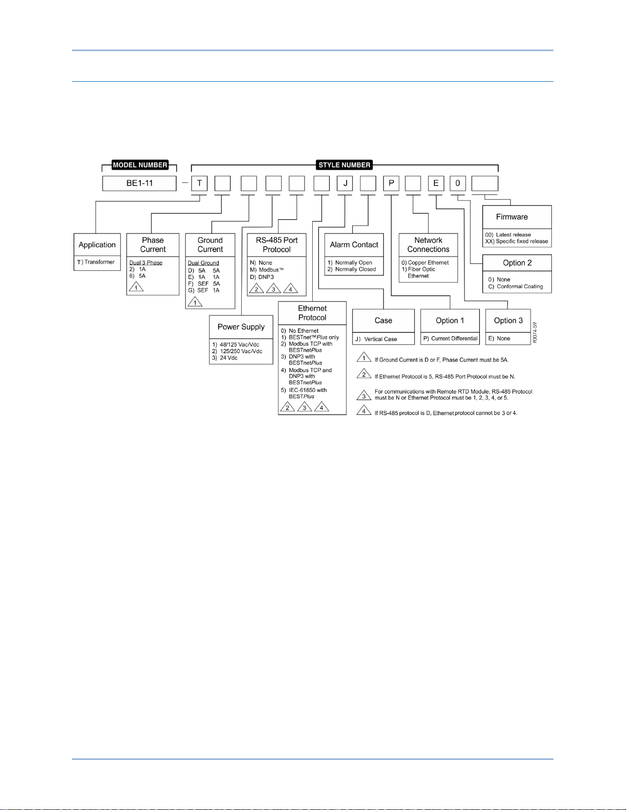
Model and Style Number Description ........................................................................................................ 8
Quick Start ................................................................................................................................................... 9
Maintenance .............................................................................................................................................. 9
Storage ...................................................................................................................................................... 9
Install BESTCOMSPlus® Software ............................................................................................................ 9
Power Up and Activate ............................................................................................................................ 10
Programming the BE1-11t ....................................................................................................................... 13
Controls and Indicators ............................................................................................................................ 23
Illustrations and Descriptions .................................................................................................................. 23
Menu Navigation ...................................................................................................................................... 25
Front Panel Operations ........................................................................................................................... 25
Display Setup .......................................................................................................................................... 27
Contact Inputs and Outputs ..................................................................................................................... 29
Contact-Sensing Inputs ........................................................................................................................... 29
Contact Outputs ....................................................................................................................................... 32
Overexcitation (24) Protection ................................................................................................................. 37
Element Operation ................................................................................................................................... 37
Logic Connections ................................................................................................................................... 39
Operational Settings ................................................................................................................................ 39
Settings Example ..................................................................................................................................... 40
Phase Undervoltage (27P) Protection ..................................................................................................... 43
Element Operation ................................................................................................................................... 43
Logic Connections ................................................................................................................................... 44
Operational Settings ................................................................................................................................ 45
Auxiliary Undervoltage (27X) Protection ................................................................................................ 47
Element Operation ................................................................................................................................... 47
Logic Connections ................................................................................................................................... 49
Operational Settings ................................................................................................................................ 49
Negative-Sequence Voltage (47) Protection........................................................................................... 51
Phase Overvoltage (59P) Protec tion ....................................................................................................... 53
Element Operation ................................................................................................................................... 53
Logic Connections ................................................................................................................................... 54
Operational Settings ................................................................................................................................ 54
Auxiliary Overvoltage (59X) Protection .................................................................................................. 57
Element Operation ................................................................................................................................... 57
Logic Connections ................................................................................................................................... 59
Operational Settings ................................................................................................................................ 59
Frequency (81) Protection ........................................................................................................................ 61
Frequency Measurement......................................................................................................................... 61
Underfrequency and Overfrequency Protection ...................................................................................... 61
Frequency Rate-of-Change Protection .................................................................................................... 62
Logic Connections ................................................................................................................................... 64
Operational Settings ................................................................................................................................ 64
Negative-Sequence Overcurrent (46) Protection ................................................................................... 67
Pickup Settings ........................................................................................................................................ 67
Coordination Settings .............................................................................................................................. 68
BE1-11t Contents
Page 6

iv 9424200995 Rev H
Instantaneous Overcurrent (50) Protection ............................................................................................ 69
Element Operation ................................................................................................................................... 69
Logic Connections ................................................................................................................................... 70
Operational Settings ................................................................................................................................ 71
Breaker Failure (50BF) Protection ........................................................................................................... 73
Element Operation ................................................................................................................................... 73
Logic Connections ................................................................................................................................... 74
Operational Settings ................................................................................................................................ 75
Inverse Overcurrent (51) Protection ........................................................................................................ 77
Element Operation ................................................................................................................................... 77
Logic Connections ................................................................................................................................... 82
Operational Settings ................................................................................................................................ 82
Directional Overcurrent (67) Protection .................................................................................................. 85
Polarization Methods ............................................................................................................................... 85
Maximum Torque Angle and Directional Tests ....................................................................................... 87
Theory of Using Sequence Impedances for Fault Direction .................................................................... 88
Phase Current Differential (87) Prote ction ............................................................................................. 91
Element Operation ................................................................................................................................... 91
Logic Connections ................................................................................................................................... 94
Settings .................................................................................................................................................... 95
Neutral Current Differential (87N) Protection ......................................................................................... 99
Element Operation ................................................................................................................................... 99
Logic Connections ................................................................................................................................. 101
Operational Settings .............................................................................................................................. 102
Resistance Temperature Detector (49RTD) Protection ....................................................................... 103
Element Operation ................................................................................................................................. 103
Logic Connections ................................................................................................................................. 104
Operational Settings .............................................................................................................................. 104
Remote RTD Metering........................................................................................................................... 105
Analog Input Protection ......................................................................................................................... 107
Element Operation ................................................................................................................................. 107
Logic Connections ................................................................................................................................. 108
Operational Settings .............................................................................................................................. 108
Remote Analog Input Metering .............................................................................................................. 109
Virtual Control Switches (43) ................................................................................................................. 111
Element Operation ................................................................................................................................. 111
Logic Connections ................................................................................................................................. 113
Operational Settings .............................................................................................................................. 113
Logic Timers (62) .................................................................................................................................... 115
Element Operation ................................................................................................................................. 115
Logic Connections ................................................................................................................................. 118
Operational Settings .............................................................................................................................. 118
Lockout Functions (86) ........................................................................................................................... 121
Element Operation ................................................................................................................................. 121
Logic Connections ................................................................................................................................. 121
Operational Settings .............................................................................................................................. 121
Retrieving Lockout Status from the BE1-11t ......................................................................................... 122
Breaker Control Switch (101) ................................................................................................................. 123
Element Operation ................................................................................................................................. 123
Logic Connections ................................................................................................................................. 124
Operational Settings .............................................................................................................................. 125
Contents BE1-11t
Page 7

9424200995 Rev H v
Setting Groups ........................................................................................................................................ 127
Setting Group Functions ........................................................................................................................ 127
Logic Connections ................................................................................................................................. 130
Operational Settings .............................................................................................................................. 131
Logic Override of the Setting Group Selection Function ....................................................................... 133
Metering ................................................................................................................................................... 135
Metering Explorer .................................................................................................................................. 135
Analog Metering Functions .................................................................................................................... 136
Sequence of Events ................................................................................................................................ 143
Retrieving SER Information ................................................................................................................... 143
Fault Reporting ........................................................................................................................................ 145
Fault Reporting Trigger Logic ................................................................................................................ 145
Targets .................................................................................................................................................. 145
Fault Reports ......................................................................................................................................... 148
Oscillographic Records.......................................................................................................................... 151
Distance to Fault .................................................................................................................................... 152
Protective Fault Analysis ....................................................................................................................... 154
Alarms ...................................................................................................................................................... 157
Alarm Settings ....................................................................................................................................... 159
User Programmable Alarms .................................................................................................................. 159
Retrieving Alarm Information ................................................................................................................. 160
Resetting Alarms ................................................................................................................................... 160
Differential Reporting ............................................................................................................................. 163
Breaker Monitoring ................................................................................................................................. 165
Breaker Status Reporting ...................................................................................................................... 165
Breaker Duty Monitoring ........................................................................................................................ 166
Breaker Alarms ...................................................................................................................................... 170
Demands .................................................................................................................................................. 171
Current ................................................................................................................................................... 171
Power..................................................................................................................................................... 172
Retrieving Demand Reporting Information ............................................................................................ 172
Load Profile ............................................................................................................................................. 175
Setting the Load Profile Re c ording F uncti on ......................................................................................... 175
Retrieving Load Profile Recorded Data ................................................................................................. 175
Power Quality .......................................................................................................................................... 177
Power Quality Settings .......................................................................................................................... 177
Retrieving Power Quality Data .............................................................................................................. 177
Trip Circuit Monitor (52TCM).................................................................................................................. 181
Element Operation ................................................................................................................................. 181
Logic Connections ................................................................................................................................. 185
Operational Settings .............................................................................................................................. 186
Fuse Loss (60FL) ..................................................................................................................................... 187
Element Operation ................................................................................................................................. 187
Logic Connections ................................................................................................................................. 189
Operational Settings .............................................................................................................................. 189
Transformer Monitor (51TF) ................................................................................................................... 191
Element Operation ................................................................................................................................. 191
Logic Connections ................................................................................................................................. 192
Operational Settings .............................................................................................................................. 192
Transformer Damage Report ................................................................................................................ 193
BE1-11t Contents
Page 8

vi 9424200995 Rev H
BESTnet™Plus ......................................................................................................................................... 195
Status Page ........................................................................................................................................... 195
Real Time Data ...................................................................................................................................... 195
Demand Data ........................................................................................................................................ 196
Faults ..................................................................................................................................................... 197
Sequence of Events .............................................................................................................................. 199
Power Quality ........................................................................................................................................ 199
Mounting .................................................................................................................................................. 201
Case Cutouts and Dimensions .............................................................................................................. 201
Terminals and Connectors ..................................................................................................................... 211
Terminal Blocks ..................................................................................................................................... 212
CT Polarity ............................................................................................................................................. 212
Typical Connections ............................................................................................................................... 215
Power System Applications ................................................................................................................... 219
BESTCOMSPlus® Software .................................................................................................................... 223
Installation ............................................................................................................................................. 224
Activate the BE1-11 Plugin for BESTCOMSPlus® ................................................................................ 224
Menu Bars ............................................................................................................................................. 229
Settings Explorer ................................................................................................................................... 231
Metering Explorer .................................................................................................................................. 232
Settings File Management ..................................................................................................................... 232
Auto Export Metering ............................................................................................................................. 234
BESTCOMSPlus® Updates ................................................................................................................... 235
Firmware Updates ................................................................................................................................. 235
BESTlogic™Plus ...................................................................................................................................... 237
Overview of BESTlogic™Plus ................................................................................................................ 237
Logic Schemes ...................................................................................................................................... 245
Programming BESTlogic ™Plus.............................................................................................................. 252
Offline Logic Simulator .......................................................................................................................... 253
BESTlogic™Plus File Management ....................................................................................................... 253
BESTlogic™Plus Ex amp les ................................................................................................................... 255
Communication ....................................................................................................................................... 257
Connections ........................................................................................................................................... 257
Ethernet Setup ....................................................................................................................................... 258
Email Setup ........................................................................................................................................... 260
RS-485 Setup ........................................................................................................................................ 261
DNP Setup ............................................................................................................................................. 261
Modbus™ Setup ..................................................................................................................................... 265
Security .................................................................................................................................................... 267
Access Levels ........................................................................................................................................ 267
Username Setup .................................................................................................................................... 267
Port Access Setup ................................................................................................................................. 268
Access Control ...................................................................................................................................... 269
Viewing the Security Log ....................................................................................................................... 270
Timekeeping ............................................................................................................................................ 271
Clock Setup ........................................................................................................................................... 271
Setting the Time and Date ..................................................................................................................... 272
IRIG Port ................................................................................................................................................ 273
Real-Time Clock Specificat ions ............................................................................................................. 273
Backup Battery for the Real-Time Clock ............................................................................................... 274
Device Information .................................................................................................................................. 277
Style Number ......................................................................................................................................... 277
Contents BE1-11t
Page 9

9424200995 Rev H vii
Device Info ............................................................................................................................................. 277
Firmware Updates ................................................................................................................................. 278
Configuration ........................................................................................................................................... 281
Power System Measurements .............................................................................................................. 281
Power System Settings ......................................................................................................................... 284
Sensing Transformers Settings ............................................................................................................. 285
Transformer Setup ................................................................................................................................. 287
Display Units .......................................................................................................................................... 297
Introduction to Testing ........................................................................................................................... 299
Testing Philosophies ............................................................................................................................. 299
Testing and Troubleshooting Aids ......................................................................................................... 300
Acceptance Testing ................................................................................................................................ 303
Test Equipment ..................................................................................................................................... 303
Power Up ............................................................................................................................................... 303
Communications .................................................................................................................................... 303
Style Number and Serial Number Verificat io n ....................................................................................... 303
IRIG Verification (if used) ...................................................................................................................... 304
Contact Sensing Inputs ......................................................................................................................... 304
Control Outputs ..................................................................................................................................... 304
Current Circuit Verification..................................................................................................................... 305
Three-Phase Voltage Circuit Verification .............................................................................................. 306
Power Reading Verification ................................................................................................................... 307
Auxiliary Voltage Input Verificati on - VX and VX 3
rd
(Fundamental and Third Harmonic) ..................... 307
Frequency Verification ........................................................................................................................... 308
Commissioning Testing ......................................................................................................................... 309
Digital I/O Connection Verification ......................................................................................................... 309
Virtual Selector Switches ....................................................................................................................... 310
Virtual Contro l Sw i tc h ............................................................................................................................ 310
Protection and Control Function Verification ......................................................................................... 311
Verify Other Setpoints as Appropriate ................................................................................................... 311
Reporting and Alarm Functions ............................................................................................................. 311
Periodic Testing ...................................................................................................................................... 315
Settings Verification ............................................................................................................................... 315
Analog Circuit Verification ..................................................................................................................... 315
Overexcitation (24) Test ......................................................................................................................... 317
Functional Test Procedure .................................................................................................................... 317
Functional Test Report .......................................................................................................................... 321
Phase Undervoltage (27P) Test ............................................................................................................. 323
Functional Test Procedure .................................................................................................................... 323
Functional Test Report .......................................................................................................................... 325
Auxiliary Undervoltage (27X) Test ......................................................................................................... 327
Functional Test Procedure .................................................................................................................... 327
Functional Test Report .......................................................................................................................... 336
Phase Overvoltage (59P) Test................................................................................................................ 339
Functional Test Procedure .................................................................................................................... 339
Functional Test Report .......................................................................................................................... 341
Auxiliary Overvoltage (59X) Test ........................................................................................................... 343
Functional Test Procedure .................................................................................................................... 343
Functional Test Report .......................................................................................................................... 351
Frequency (81) Test ................................................................................................................................ 355
Functional Test Procedure .................................................................................................................... 355
Functional Test Report .......................................................................................................................... 360
BE1-11t Contents
Page 10

viii 9424200995 Rev H
Instantaneous Overcurrent (50) Test .................................................................................................... 363
Functional Test Procedure .................................................................................................................... 363
Functional Test Report .......................................................................................................................... 370
Breaker Fail (50BF) Test ......................................................................................................................... 375
Functional Test Procedure .................................................................................................................... 375
Functional Test Report .......................................................................................................................... 378
Inverse Overcurrent (51) Test ................................................................................................................ 379
Functional Test Procedure .................................................................................................................... 379
Functional Test Report .......................................................................................................................... 389
Directional Overcurrent (67) Test .......................................................................................................... 395
Functional Test Procedure .................................................................................................................... 395
Functional Test Report .......................................................................................................................... 401
Phase Current Differential (87) Test ...................................................................................................... 403
Restrained Functional Test Procedure .................................................................................................. 403
Unrestrained Functional Test Procedure ............................................................................................... 410
Harmonic Restraint Functional Test Procedure .................................................................................... 410
Functional Test Reports ........................................................................................................................ 412
Neutral Current Differential (87N) Test ................................................................................................. 415
Functional Test Procedure .................................................................................................................... 415
Functional Test Report .......................................................................................................................... 417
Virtual Control Switches (43) Test ......................................................................................................... 419
Functional Test Procedure .................................................................................................................... 419
Functional Test Report .......................................................................................................................... 421
Logic Timers (62) Test ............................................................................................................................ 423
Functional Test Procedure .................................................................................................................... 423
Functional Test Report .......................................................................................................................... 431
Lockout Functions (86) Test .................................................................................................................. 433
Functional Test Procedure .................................................................................................................... 433
Functional Test Report .......................................................................................................................... 434
Breaker Control Switch (101) Test ........................................................................................................ 435
Functional Test Procedure .................................................................................................................... 435
Functional Test Report .......................................................................................................................... 436
Frequently Asked Questions (FAQ) ...................................................................................................... 437
Electrical/Connections ........................................................................................................................... 437
General Operation ................................................................................................................................. 437
Features ................................................................................................................................................ 438
Communications .................................................................................................................................... 438
Troubleshooting ...................................................................................................................................... 439
Communications .................................................................................................................................... 439
Inputs and Outputs ................................................................................................................................ 440
Metering/Display .................................................................................................................................... 440
General Operation ................................................................................................................................. 440
Specifications .......................................................................................................................................... 443
Operational Specifications ..................................................................................................................... 443
General Specifications........................................................................................................................... 451
Specifications - 25 Hz Operation ........................................................................................................... 459
Operational Specifications ..................................................................................................................... 459
Time Curve Characteristics.................................................................................................................... 467
Inverse Overcurrent (51) ....................................................................................................................... 467
Under/Overvoltage (27/59) .................................................................................................................... 495
Overexcitation (24) ................................................................................................................................ 499
Contents BE1-11t
Page 11

9424200995 Rev H ix
RTD Module ............................................................................................................................................. 503
Features ................................................................................................................................................ 503
Functional Description ........................................................................................................................... 503
Mounting ................................................................................................................................................ 504
Connections ........................................................................................................................................... 504
RTD Module Communications Setup Procedure .................................................................................. 508
RTD Module Plugin for BESTCOMSPlus® ............................................................................................ 511
Remote Analog Inputs Configuration .................................................................................................... 516
Remote Analog Outputs Configuration .................................................................................................. 517
Remote RTDs Configuration ................................................................................................................. 518
Specifications ........................................................................................................................................ 519
Repair .................................................................................................................................................... 522
Maintenance .......................................................................................................................................... 522
Storage .................................................................................................................................................. 522
Digital Points ........................................................................................................................................... 523
Revision History ...................................................................................................................................... 537
BE1-11t Contents
Page 12

x 9424200995 Rev H
Contents BE1-11t
Page 13

9424200995 Rev H 1
Introduction
The BE1-11t Transformer Protection System provides flexible, reliable, and economical transformer
protection, control, monitoring, and measurement functions. The BE1-11t offers phase and neutral current
differential, transformer monitor, overexcitation (V/Hz), overcurrent, directional overcurrent,
over/undervoltage, over/underfrequency, RTD (Resistance Temperature Detector) with remote module,
breaker failure protection, and fuse loss protection. It offers breaker- and trip-circuit monitoring, and
oscillography and sequential events recording. Control features include virtual selector switches, circuit
breaker control, virtual lockout, and variable-mode timers. System metering, status information, and fault
locating are available at the BE1-11t front panel and through the BE1-11t communication ports. The
capabilities of the BE1-11t make it well suited to provide comprehensive transformer protection. The
system is suitable for mounting in OEM cubicle or retrofit switchgear applications. Suitable BE1-11t
applications include transformers associated with generation step up transformers, intertie installations,
network transformer, and distribution feeder step down transformer protection.
A front-panel USB port or optional rear Ethernet port enables local communication between the BE1-11t
and a PC operating with BESTCOMSPlus® software. BESTCOMSPlus software simplifies the
commissioning process by providing a graphical interface for setting the BE1-11t and configuring a
protection and control scheme for your application. Through BESTCOMSPlus, all BE1-11t settings and
logic can be retained in a file for printing or uploading to other BE1-11t protection systems. Oscillography
and sequential events records can be retrieved from a BE1-11t, viewed, and printed.
Front-panel features include a large, backlit alphanumeric display and LED indicators that display system
parameters, BE1-11t settings, and BE1-11t status. Pushbuttons enable navigation through the display
menu, changes to settings, resetting of targets (with password access), and direct access to virtual
switches.
Applications
The capabilities of the BE1-11t make it ideally suited for applications with the following attributes:
• Transformer applications where differential protection is required
• Monitoring the through fault currents that may lead to transformer damage
• Complete control of the circuit breaker connecting the transformer to the distribution bus
• Applications where bus protection is provided by a high-speed overcurrent blocking scheme on
the transformer bus mains instead of a dedicated bus differential circuit
• Isolation between the RTDs and the BE1-11t due to distance between the BE1-11t package and
the RTD module
• Low burden to extend the linear range of CTs
• The flexibility provided by wide setting ranges, multiple setting groups, and multiple coordination
curves in one unit
• The economy and space savings provided by a multifunction, multiphase unit. This one unit can
provide all of the protection, control, metering, and local and remote indication functions required
for typical applications.
• Directional control and fault recording
• High-speed Ethernet communications and protocol support
• The capabilities of a numeric multifunction relay
• The small size and limited behind-panel projection facilitates modernizing protection and control
systems in existing equipment
• Detection of low ground current levels (SEF option)
• IEC 61850 functionality
BE1-11t Introduction
Page 14

2 9424200995 Rev H
Features
The BE1-11t protection system includes many features for the protection, monitoring, and control of
power system equipment. These features include protection and control functions, metering functions,
and reporting and alarm functions. A highly flexible programmable log ic sys tem c all ed BEST logic™Plus
allows the user to apply the available functions with complete flexibility and customize the system to meet
the requirements of the protected power system. Programmable I/O, extensive communication features,
and an advanced user interface provide easy access to the features provided.
The following information summarizes the capabilities of this multifunction device. Each feature, along
with its setup and use, is described in greater detail in the later chapters of this manual.
General Features
HMI (Human-Machine Interface)
Each BE1-11t has a front-panel display and 12 LED indicators: Power Supply Status, Relay Trouble
Alarm, Minor Alarm, Major Alarm, Trip, Select Control Switch, Operate Control Switch, and Indicator 1
through 7 (programmable in BESTlogicPlus). The backlit, liquid crystal display (LCD) allows the BE1-11t
to replace local indication and control functions such as panel metering, alarm annunciation, and control
switches. Four scrolling pushbuttons enable navigation through the LCD menu tree. Parameters are
changed using the Edit pushbutton. Targets, alarms, and other registers are cleared with the Reset
pushbutton. In Edit mode, the scrolling pushbuttons provide data entry selections. Edit mode is indicated
by an LED on the Edit pushbutton. Select Control Switch and Operate Control Switch pushbuttons
provide a means to control the logic switches.
The LCD has automatic priority logic to govern which metering values are displayed on the screen so that
when an operator approaches, the metering data of most interest is automatically displayed without
having to navigate the menu structure. Scrollable metering parameters are selected on the General
Settings, Front Panel HMI settings screen in BESTCOMSPlus.
Device Information
The version of the embedded software (firmware), serial number, and style number are available from the
front panel or the communication ports.
Three free-form fields (Device ID, Station ID, and User ID) can be used to enter information to identify the
BE1-11t. These fields are used by many of the reporting functions to identify the BE1-11t reporting the
information. Examples of BE1-11t identification field uses include station name, circuit number, relay
system, and purchase order, and others.
Device Security
Passwords provide access security for six distinct functional access areas: Read, Control, Operator,
Settings, Design, and Administrator. Each username/password is assigned an access area with access to
that area and each area below it. An administrator password provides access to all six of the functional
areas.
A second dimension of security is provided by the ability to restrict access for any of the access areas to
only specific communication ports. For example, you could set up security to deny access to control
commands through the Eth er net port.
Security settings affect read and write access. Refer to the Security chapter for more information.
Setting Groups
Four setting groups allow adaptive relaying to be implemented to optimize BE1-11t settings for various
operating conditions. Automatic and external logic can be employed to select the active setting group.
Clock
The clock is used by the logging functions to timestamp events. BE1-11t timekeeping can be selfmanaged by the internal clock or coordinated with an external source through a network or IRIG device.
Introduction BE1-11t
Page 15

9424200995 Rev H 3
A backup capacitor and additional battery backup are provided for the clock. During a loss of operating
power, the backup capacitor maintains timekeeping for up to 24 hours depending on conditions. As the
capacitor nears depletion, the backup battery takes over and maintains timekeeping. The backup battery
has a life expectancy of greater than five years depending on conditions.
IRIG
A standard unmodulated IRIG-B input receives time synchronization signals from a master clock.
Automatic daylight saving time compensation can be enabled and set for floating or fixed dates.
NTP (Network Time Protocol)
NTP synchronizes the real-time clock to network time servers through the Ethernet port. BESTCOMSPlus
is used to establish the priority of time reference sources available to the BE1-11t, IRIG-B, NTP, DNP,
and RTC (real-time clock). The NTP address is set using BESTCOMSPlus.
Communications
Three independent communication ports provide access to all BE1-11t functions. A USB (universal serial
bus) port is located on the front panel, a two-wire RS-485 port is located on the rear panel, and an
optional Ethernet port is also located on the rear panel. The RS-485 and Ethernet ports are electrically
isolated.
Modbus™ and DNP3 protocols are optionally available for the RS-485 or Ethernet communication port.
The IEC 61850 protocol is optionally av ai lable for the Ether net port. Sep ar ate instruction manuals cover
each available protocol. Consult the product bulletin or Basler Electric for availability of these options and
instruction manuals. Modbus sessions can be operated simultaneously over the Ethernet and RS-485
ports.
System Parameters
Three-phase currents and voltages are digitally sampled and the fundamental is extracted using a
Discrete Fourier Transform (DFT) algorithm.
The voltage sensing circuits can be configured for single-phase, three-phase-three-wire, or four-wire
voltage transformer circuits. Voltage sensing circuitry provides voltage protection, frequency protection,
polarizing, and watt/var metering. Neutral-shift, positive-sequence, and negative-sequence voltage
magnitudes are derived from the three-phase voltages. Digital sampling of the measured frequency
provides high accuracy at off-nominal values.
An auxiliary voltage sensing input (Vx) provides protection capabilities for over/undervoltage monitoring of
the fundamental and third harmonic voltage of the VT source connected to the Vx input. This capability is
useful for ground fault protection.
Each current sensing circuit has low burden and is isolated. Neutral, positive-sequence, and negativesequence current magnitudes are derived from the three-phase curr ents . An ind e pend ent ground current
input is available for direct measurement of the current in a transformer neutral, tertiary winding or flux
balancing current transformer.
Programmable Inputs and Outputs
Programmable contact inputs and outputs are described in the following paragraphs.
Programmable Inputs
Seven programmable contact sensing inputs with programmable signal conditioning provide a binary logic
interface to the protection and control system. Each input function and label is programmable using
BESTlogicPlus. A user -meaningful label can be assigned to each input and to each state (energized and
de-energized) for use in reporting functions. Board mounted jumpers support dual voltage ratings.
Programmable Outputs
Eight programmab le gen er al-purpose contact outputs provide a binary logic interface to the protection
and control system. One programmable, failsafe contact output serves as an alarm output. Each output
BE1-11t Introduction
Page 16

4 9424200995 Rev H
function and label is programmable using BESTlogicPlus. A user-meaningful name can be assigned to
each output and to each state (energized and de-energized) for use in reporting functions. Output logic
can be overridden to open, close, or pulse each output contact for testing or control purposes. All output
contacts are trip rated.
Reporting and Alarms
Several reporting and alarm functions provide fault reporting, differential reporting, demand, breaker, and
trip circuit monitoring. Reporting of power quality, energy data, and general status is also provided.
Alarms
Extensive self diagnostics will trigger a fatal relay trouble alarm if any of the BE1-11t core functions are
compromised. Fatal relay trouble alarms are not programmable and are dedicated to the Alarm output
(OUTA) and the front panel Relay Trouble LED. Additional relay trouble alarms and all other alarm
functions are programmable for major or minor priority. Programmed alarms are indicated by major or
minor alarm LEDs on the front panel. Major and minor alarm points can also be programmed to any
output contact including OUTA. Over 50 alarm conditions are available to be monitored including userdefinable logic conditions u sing BE STlogicPlus.
Active alarms can be read and reset at the front panel or through the communication ports. A historical
sequence of events report with time stamps lists when each alarm occurred and cleared. These reports
are available through the communication ports.
Breaker Monitoring
Breaker statistics are recorded for a single breaker. They include the number of operations, fault current
interruption duty, and breaker time to trip. Each of these conditions can be set to trigger an alarm.
Transformer Monitor (51TF)
The 51TF (through-fault) monitor measures the current flowing through a transformer and compares the
current magnitude and duration to a damage characteristic defined by the user. When the current
exceeds the threshold setting, a through-fault pickup counter increments to indicate the excessive current.
If the duration of the current exceeds the damage characteristic, a through-fault duration counter
increments. The pickup counter or duration counter can be used to trigger a 51TF through-fault alarm
which would prompt inspection of the transformer. The number of counts for each counter is shown on the
Transformer Damage Report screen in BESTCOMSPlus.
Trip Circuit Monitor (52TCM)
The trip circuit of a breaker or lockout relay can be monitored for loss of voltage (fuse blown) or loss of
continuity (trip coil open). Additional trip or close circuit monitors can be implemented in BESTlogicPlus
using additional inputs, logic timers, and programmable logic alarms.
Demands
Demand values are continuously calculated for phase currents, neutral current, negative-sequence
current, ground current, real power, reactive power, and apparent power. The demand interval and
demand calculation method are independently settable for phase, neutral, and negative-sequence
measurements. Demand reporting records peak and present demand with time stamps for each register.
Power Quality
The BE1-11t offers IEC 61000-4-30 Class B power quality measurement performance. Power quality
settings include a fixed or sliding reference mode, dip hysteresis, dip ratio, swell hysteresis, and swell
ratio.
Energy Data Reporting
Energy information in the form of watthours and varhours is measured and reported by the BE1-11t. Both
positive and negative values are reported in three-phase, primary units.
Introduction BE1-11t
Page 17

9424200995 Rev H 5
General Status Reporting
The BE1-11t provides extensive general status reporting for monitoring, commissioning, and
troubleshooting. Status reports are available from the front panel or communication ports.
Fault Reporting
Fault reports consist of simple target information, fault summary reports, and detailed oscillography
records to enable the user to retrieve information about disturbances in as much detail as is desired. The
BE1-11t records and reports oscillography data in industry-standard IEEE, COMTRADE format to allow
using any fault analysis software. Basler Electric provides a Windows
BESTwave™ that can read and plot binary or ASCII format files that are in the COMTRADE format. A
copy of BESTwave is included on the BE1-11 product CD.
Sequence of Events Recorder
A Sequence of Events Recorder (SER) records and time stamps all BE1-11t inputs and outputs as well as
all alarm conditions monitored by the BE1-11t. Time stamp resolution is to the nearest half-cycle. I/O and
Alarm reports can be extracted from the records as well as reports of events recorded during the time
span associated with a specific fault report.
® based program called
Protection and Control
Protection functions consist of Overexcitation, Undervoltage, Overvoltage, Frequency, Instantaneous
Overcurrent, Breaker Failure, Inverse Overcurrent, Phase Current Differential, Neutral Current
Differential, Thermal, and Analog protection. Virtual Control Switches, Timers, a Lockout Function, and a
Breaker Control Switch make up the control functions. The following paragraphs describe each protection
and control function.
Overexcitation (24) Protection
One volts per hertz protective element provides overexcitation protection for a generator and/or
transformer.
Undervoltage (27P) and Overvoltage (59P) Protection
Five phase undervoltage and four phase overvoltage elements are included. Phase
undervoltage/overvoltage protection can be set for one of three, two of three, or three of three logic.
When a four-wire voltage transformer connection is used, under/overvoltage protection can be set for
either phase-to-phase voltage or phase-to-neutral voltage. The 27P elements are equipped with an
undervoltage inhibit feature. Inverse or definite time can be selected. Refer to the T ime Cur ve
Characteristics chapter.
Auxiliary Undervoltage (27X) and Auxiliary Overvoltage (59X) Protection
Four auxiliary overvoltage and four auxiliary undervoltage elements provide over/undervoltage protection.
Auxiliary voltage protection elements can be set to monitor separately the third harmonic, neutral-shift,
positive-sequence, negative-sequence, or auxiliary fundamental voltages. Ground unbalance protec ti on is
provided when the auxiliary voltage input is connected to a source of 3V0 such as a broken-delta VT. The
27X is equipped with an undervoltage inhibit feature. Inverse or definite time can be selected. Refer to the
Time Curve Characteristics chapter.
Frequency (81) Protection
Eight independent frequency elements can be set for over, under, or rate of change (81R) frequency
operation. Each can be set separately to monitor the frequency on the main three-phase voltage input or
the Vx input. Rate of change can be set to operate on positive, negative, or “either”.
BE1-11t Introduction
Page 18

6 9424200995 Rev H
Note
Note
BE1-11t protection systems enabled for IEC-61850 communication
(style Txxxx5xxxxxxxx) have their frequency protection elements fixed
at four underfrequency elements, two overfrequency elements, and
two frequency rate-of-change elements.
Instantaneous Overcurrent (50) Protection
Directional overcurrent protection is provided by nine instantaneous overcurrent elements. Digital signal
processing filters out unwanted harmonic components while providing fast overcurrent response with
limited transient overreach and overtravel.
Instantaneous overcurrent elements can be set for single-phase, three-phase, ground, neutral, positivesequence, negative-sequence, or unbalanced protection.
Breaker Failure (50BF) Protection
One breaker failure function provides protection and security for the power system against failure of the
monitored breaker.
Inverse Overcurrent (51) Protection
Nine inverse overcurrent elements can be set for single-phas e, three-phase, ground, neutral, positivesequence, negative-sequence, or unbalanced protection. Inverse-overcurrent functions employ a dynamic
integrating timing algorithm covering a range from pickup to 40 times pickup with selectable
instantaneous or integrated reset characteristics. Inverse time overcurrent curves conform to IEEE Std
C37.112-1996 - IEEE Standard Inverse-Time Characteristic Equations for Overcurrent Relays, and
include seven curves similar to Westinghouse/ABB CO curves, five curves similar to GE IAC curves, a
fixed time curve, and a user programmable curve. Refer to the Time Curve Characteristics chapter for
more information about the inverse overcurrent protection characteristic curves.
Phase inverse overcurrent elements can be voltage restrained or controlled for generator backup
applications. Negative-sequence current protection (46) is included as a mode of the 51 (inverse
overcurrent) element. Each inverse overcurrent element can be set separately for forward, reverse, or
non-directional control.
A separate ground current input provides ground overcurrent protection for a separate ground CT.
Optionally, an SEF (sensitive earth fault) version of the separate ground CT is available.
BE1-11t protection systems enabled for IEC-61850 communication
(style Txxxx5xxxxxxxx) have their inverse overcurrent protection
elements fixed at nine inverse overcurrent elements without voltage
control.
Phase Current Differential (87) Protection
One phase current differential element provides three-phase, percent age-restrained, differential
protection with dual-slope.
Neutral Current Differential (87N) Protection
Two neutral current differential elements provides sensitive phase-to-ground fault differential protection
for the wye winding of the transformer.
Resistance Temperature Detector (49RTD) Protection
Fourteen resistance temperature detector elements provide over/undertemperature protection in
applications where a remote RTD module is connected to the BE1-11t via Ethernet or RS-485 cable. For
more information, refer to the RTD Module chapter.
Introduction BE1-11t
Page 19

9424200995 Rev H 7
Analog Input Protection
Eight analog input protection elements monitor external analog input signals when two remote RTD
modules are connected via an Ethernet or RS-485 cable. Four analog inputs are provided with each RTD
module. For more information, refer to the RTD Module chapter.
Fuse Loss (60FL)
A fuse loss element protects against false tripping due to a loss of voltage sensing. Voltage transformer
circuit monitoring adds security by detecting problems in the voltage transformer sensing circuits and
preventing mis-operations of the 27P, 47, 59P, and 51/27 functions.
Breaker Control Switch (101)
Tripping and closing of a selected breaker can be controlled by the virtual breaker control switch. The
virtual breaker control switch is accessed locally at the front panel or remotely through the communication
ports.
Virtual Control Switches (43)
Five virtual control switches are accessed locally at the front panel or remotely through the
communication ports. Virtual switches can be used to trip and close additional switches or breakers, or
enable and disable certain functions.
Logic Timers (62)
Eight logic timers with six modes of operation emulate virtually any type of timer.
Lockout Functions (86)
Two lockout elements are provided.
BESTlogic™Plus Programmable Logic
Each BE1-11t protection and control function is implemented in an independent function element. Every
function block is equivalent to its single function, discrete device counterpart so it is immediately familiar
to the protection engineer. Each independent function block has all of the inputs and outputs that the
discrete component counterpart may have. Progr a mm i ng with BEST logicPlus is equivalent to choosing
the devices required by your protection and control scheme and then drawing schematic diagrams to
connect the inputs and outputs to obtain the desired operating logic.
Refer to the BESTlogicPlus chapter for more information on logic schemes. Custom logic settings allow
you to tailor the BE1-11t functionality to match the needs of your operation's practices and power system
requirements.
Metering Functions
Metering is provided for the following parameters:
• Primary and secondary voltages (P-P, P-N, V1, V2, 3V0, Vx, Vx 3
• Frequency (phase and auxiliary)
• Primary and secondary currents (phase, ground, I1, I2, 3I0)
• Power (real, reactive, apparent)
• Power factor
nd
• Phase differential (Iop, Ir, 2
Harmonic, 5th Harmonic)
• Neutral differential (Iop)
• Energy (total watthours and total varhours)
rd
harmonic)
For details on metering functions, refer to the Metering chapter.
BE1-11t Introduction
Page 20
8 9424200995 Rev H
Model and Style Number Description
BE1-11t electrical characteristics and operational features are defined by a combination of letters and
numbers that make up the style number. The style number describes the options included in a specific
device and appears on labels located on the front panel and inside the case. Upon receipt of a BE1-11t,
be sure to check the style number against the requisition and the packing list to ensure that they agree.
The model number and style number are shown in Figure 1.
Figure 1. Style Chart
Introduction BE1-11t
Page 21

9424200995 Rev H 9
Note
Quick Start
This chapter provides basic installation and setup information about the BE1-11t Tr ans former Protec t ion
System. BE1-11t protection systems are delivered with a BE1-11 product CD. Upon receipt of the
BE1-11t, check the model and style number against the requisition and packing list for agreement. If there
is evidence of shipping damage, file a claim with the carrier, and notify the Basler Electric Regional Sales
Office, your sales representative, or a sales representative at Basler Electric, Highland, Illinois.
If the BE1-11t is not installed immediately, store it in the original shipping carton in a moisture- and dustfree environment.
Included on the BE1-11 product CD:
• BESTCOMSPlus® Software
• BESTwave™ Software
• BEST61850™ Software
• Quick Start Guide
• Communications Quick Start Guide
• Instruction Manual
• Modbus™ Instruction Manual
• DNP Instruction Manual
• IEC 61850 Instruction Manual
Do not connect a USB cable between the PC and the BE1-11t until
BESTCOMSPlus is installed. Connecting a USB cable before setup is
complete may result in errors.
Maintenance
Preventive maintenance consists of periodic replacement of the backup battery and periodically checking
that the connections between the BE1-11t and the system are clean and tight. The front cover should be
removed only when replacing the backup battery for the real-time clock. Ensure that the BE1-11t is
powered off and taken out of service before removing the front cover. BE1-11t units are manufactured
using state-of-the-art, surface-mount technology. As such, Basler Electric recommends that no repair
procedures be attempted by anyone other than Basler Electric personnel.
Storage
This device contains long-life aluminum electrolytic capacitors. For devices that are not in service (spares
in storage), the life of these capacitors can be maximized by energizing the device for 30 minutes once
per year.
Install BESTCOMSPlus® Software
BESTCOMSPlus software is built on the Microsoft® .NET Framework. The setup utility that installs
BESTCOMSPlus on your PC also installs the BE1-11 plugin and the required version of .NET Framework
(if not already installed). BESTCOMSPlus operates with systems using Windows® XP 32-bit SP3,
Windows Vista 32-bit SP1 (all editions), Windows 7 32-bit (all editions), Windows 7 64-bit (all editions),
and Windows 8. System recommendations for the .NET Framework and BESTCOMSPlus are listed in
Table 1.
BE1-11t Quick Start
Page 22

10 9424200995 Rev H
System Type
Component
Recommendation
32/64 bit
Processor
2.0 GHz
32/64 bit
RAM
1 GB (minimum), 2 GB (recommended)
32 bit
Hard Drive
100 MB (if .NET Framework is already installed on PC)
950 MB (if .NET Framework is not already installed on PC)
64 bit
Hard Drive
100 MB (if .NET Framework is already instal led on PC)
2.1 GB (if .NET Framework is not already installed on PC)
Table 1. System Recommendations for BESTCOMSPlus and the .NET Framework
To install BESTCOMSPlus, a Windows user must have Administrator rights.
1. Insert the BE1-11 product CD into the PC CD-ROM drive.
2. When the BE1-11 Product CD menu appears, click the installation button for BESTCOMSPlus. The
setup utility installs BESTCOMSPlus, the .NET Framework (if not already installed), the USB driver,
and the BE1-11 plugin for BESTCO M SPlus on your PC.
When BESTCOMSPlus installation is complete, a Basler Electric folder is added to the Windows
programs menu. This folder is accessed by clicking the Windows Start button and then accessing the
Basler Electric folder in the Programs menu. The Basler Electric folder contains an icon that starts
BESTCOMSPlus when clicked.
Power Up and Activate
The BE1-11 plugin is a module that runs inside the BESTCOMSPlus shell. The BE1-11 plugin contains
specific operational and logic settings for only BE1-11 protection systems. Uploading settings to the
BE1-11t is possible only after activat ing the B E1-11 plugin.
Note that if a BE1-11t is not connected, you will not be able to configure certain Ethernet settings.
Ethernet settings can be changed only when an active USB or Ethernet connection is present. Refer to
the Communication chapter for more information.
USB Connection
The USB driver was copied to your PC during BESTCOMSPlus installation and is
installed automatically after powering the BE1-11t. USB driver installation progress is
shown in the Windows Taskbar area. Windows will notify you when installation is
complete.
Connect a USB cable between the PC and your BE1-11t protection system. A typical
USB cable with a B-type connector is shown to the right.
NOTE
In some instances, the Found New Hardware Wizard will prompt you for the
USB driver. If this happens, direct the wizard to the following folder:
C:\Program Files\Basler Electric\USB Device Drivers\
Apply Operating Power
The nominal power supply values are listed on the front-panel label. See Figure 2 for an example.
Quick Start BE1-11t
Page 23
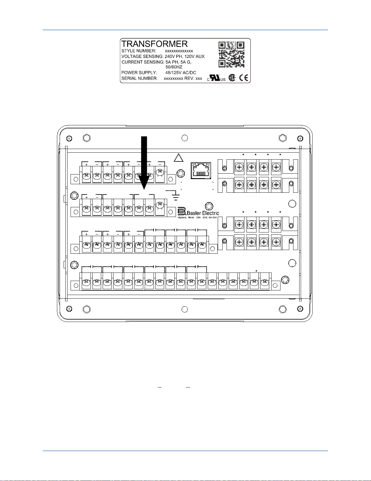
9424200995 Rev H 11
ETHERNET
!
WARNING
BE1-11
C12C11C10C9C8C7C6C5C4C3C2C1 C13 C14 C15 C16 C17 C18
V
A
OUT 2 OUT 3 OUT 4 OUT 5OUT 1 ALARM VBV
C
V
X
VXN
E12E11E10E9E8E7E6E5E4E3E2E1
OUT 8 OUT 7
IN5 IN6
IN7
OUT 6
A8A7A6A5A4A3A2A1
IRIG PWR
CA B
COM2 RS-485
GND
B8B7B6B5B4B3B2B1
IN1 IN2
IN3
IN4
D1 D3 D5 D7
IA1IB1IC1I
G1
I
A1
D2 D4 D6 D8
IB1IC1I
G1
I
A2
F2 F4 F6 F8
IB2IC2I
G2
F1 F3 F5 F7
IA2I
B1
IC2I
G2
P0061-43
Figure 2. Front Panel Label Example
Connect rear terminals A6, A7, and A8 (groun d) to a power supp ly. See Figure 3. Apply operating power
consistent with the nominal power supply values listed on the front-panel label. Wait until the boot
sequence is complete.
Start BESTCOMSPlus® and Activate BE1-11 Plugin
To start BESTCOMSPlus, click the Start button, point to Programs, Basler Electric , and then click the
BESTCOMSPlus icon. During initial startup, the BESTCOMSPlus Select Language screen is displayed
(Figure 4
can select a preferred language and this screen will be bypassed in the future. Click OK to continue. This
screen can be accessed later by selecting Tools and Select Language from the menu bar.
BE1-11t Quick Start
Figure 3. PWR Rear Terminals
). You can choose to have this screen displayed each time BESTCOMSPlus is started, or you
Page 24
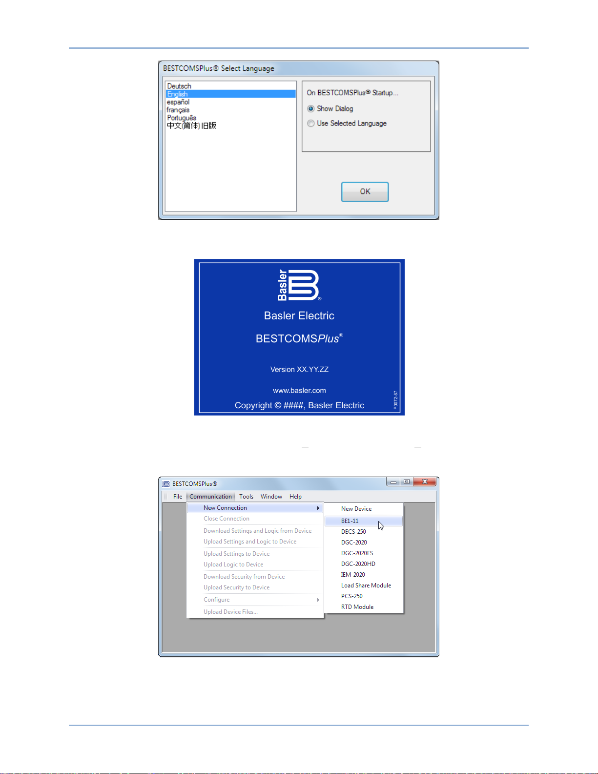
12 9424200995 Rev H
Figure 4. BESTCOMSPlus Select Language Screen
The BESTCOMSPlus splash screen is shown for a brief time. See Figure 5.
Figure 5. BESTCOMSPlus Splash Screen
The BESTCOMSPlus platform window opens. Select New Connection from the Communication pull-down
menu and select BE1-11. See Figure 6. The BE1-11 plugin is activated automatically after connecting to a
BE1-11t.
Figure 6. Communication Pull-Down Menu
The BE1-11 Connection screen shown in Figure 7 appears. Select USB Connection and then click the
Connect button.
Quick Start BE1-11t
Page 25
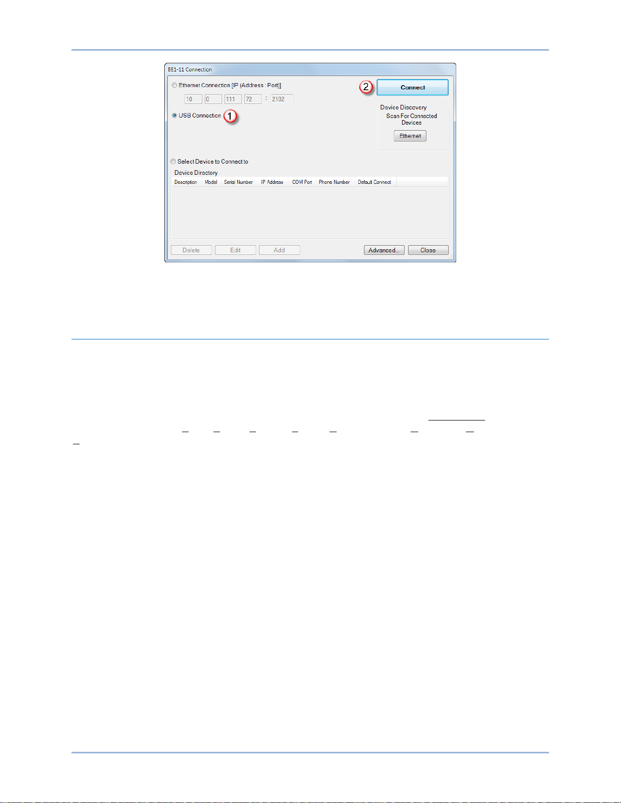
9424200995 Rev H 13
Figure 7. BE1-11 Connection Screen
The BE1-11 plugin opens indicating that activation was successful. You can now configure the BE1-11t
communication ports and other BE1-11t settings.
Programming the BE1-11t
This section contains an introduction to BESTCOMSPlus, explains summary screens, and gives an
example of settings elements and programming logic.
Introduction to BESTCOMSPlus®
BESTCOMSPlus is a Windows®-based, PC application that provides a user-friendly, graphical user
interface (GUI) for use with Basler Electric communicating products. The name BESTCOMSPlus is an
acronym that stands for Basler Electric Software Tool for Communications, Operations, Maintenance, and
Settings.
BESTCOMSPlus provides the user with a point-and-click means to set and monitor the BE1-11t. The
capabilities of BESTCOMSPlus make the configuration of one or several BE1-11t T rans for mer Pr otection
Systems fast and efficient. A primary advantage of BESTCOMSPlus is that a settings scheme can be
created, saved as a file, and then uploaded to the BE1-11t at the user’s conv e nie nce.
The BE1-11 plugin opens inside the B ESTCO M S Plus main shell. The same default logic scheme that is
shipped with the BE1-11t is brought into BESTCOMSPlus by downloading settings and logic from the
BE1-11t or by selecting application type “T” on the Style Number screen. This gives the user the option of
developing a custom setting file by modifying the default logic scheme or by building a unique scheme
from scratch.
BESTlogic™Plus Programmable Logic is used to program BE1-11t logic for protection elements, inputs,
outputs, alarms, etc. This is accomplished by the drag-and-drop method. The user can drag elements,
components, inputs, and outputs onto the program grid and make connections between them to create
the desired logic scheme.
BESTCOMSPlus also allows for downloading industry-standard COMTRADE files for analysis of stored
oscillography data. Detailed analysis of the oscillography files can be accomplished using BESTwave
software.
Figure 8 illustrates the typical user interface components of the BE1-11 plugin with BESTCOMSPlus.
BE1-11t Quick Start
Page 26
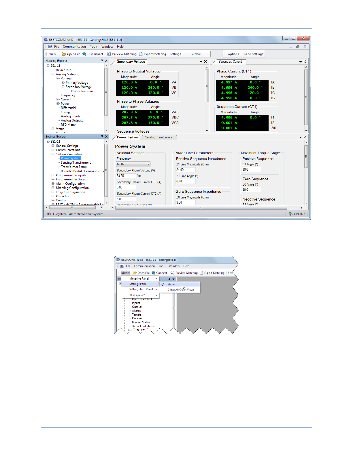
14 9424200995 Rev H
Figure 8. BESTCOMSPlus Typical User Interface Components
Click the View drop-down button to switch between the Settings Explorer and Metering Explorer or split
the view between both. The Settings Info Panel displays settings ranges. A workspace can be opened,
saved, or set as default. See Figure 9.
Figure 9. View Drop-Down Button
Summary Screens
Summary screens provide an overview of the system setup. The legend, located in the lower right-hand
corner, provides interpretation for the various indicated colors. The current state of a protection and
control function or element is indicated by the color of the adjacent indicator. If the function is enabled, the
color is green. If the function is disabled only by a setting (such as zero), the color is yellow. If the function
is disabled only by a mode, the color is blue. If the function is disabled by both a setting and mode, the
color is gray. The System Summary screen is available by clicking BE1-11 in the Settings Explorer as
shown in Figure 10. Summary screens are also available for General Settings, Alarm Configuration,
Protection, and Control.
Quick Start BE1-11t
Page 27
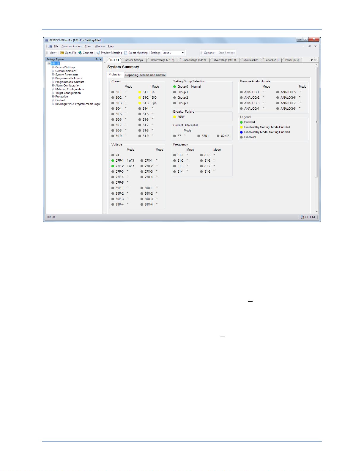
9424200995 Rev H 15
Figure 10. System Summary Screen
Programming Example
Changing default logic is sometimes required to match the protection requirements of the system.
Additionally, elements must be enabled and operating settings set. This example demonstrates how to
configure typical nominal settings and program the 50-3 instantan eous ov erc ur rent elem ent. Sy s tem
nominal quantities are set to 69.3 volts and 3.6 amps. The 50-3 element is set for a 5.62 amp pickup and
a 30 second time delay. Additionally, the element pickup output is logically wired to output 4 and a user
alarm.
Step 1: Star t BE ST C OMSPlus and select New Connection, BE1-11 from the Communication pull-down
menu to connect to the BE1-11t. See Figure 6.
Step 2: The BE1-11 Connection screen appears. See Figure 7. Select USB Connection and click
Connect.
Step 3: Select Download Settings and Logic from Device from the Communication pull-down menu. This
copies all settings and logic from the BE1-11t to BESTCOMSPlus.
Step 4: Click on the View drop-down button and de-select Show Metering Panel and Show Setting
Information. See Figure 9. This maximizes the workspace.
Step 5: In the Settings Explorer, click the “+” next to BE1-11. This expands the sub menus in the tree.
Now expand System Parameters and select the Power System screen. See Figure 11.
Step 6: Under Nominal Settings, enter settings for Secondary Phase Voltage (69.3 V) and Secondary
Phase Current (3.6 A).
Step 7: In the Settings Explorer, expand Protection, Current and select the Instantaneous Overcurrent
(50-3) screen. See Figure 12.
Step 8: Select the Mode (3 Phase) and enter settings for Pickup (5.62 A) and Time Delay (30,000 ms).
BE1-11t Quick Start
Page 28
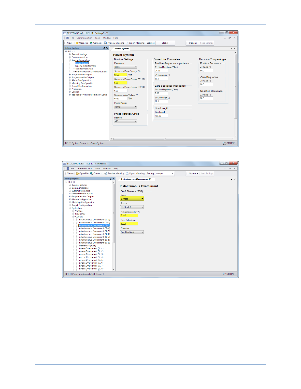
16 9424200995 Rev H
Figure 11. Power System Screen
Figure 12. Instantaneous Overcurrent (50-3) Screen
Step 9: In the Settings Explorer, click BESTlogicPlus Programmable Logic to open the logic diagram.
Click the Current tab. See Figure 13. Examine the 50-3 element. The Logic 0 connected to the
Block input indicates that the 50-3 element is never blocked.
Off-Page Inputs/Outputs are used to make connections between logic pages and help keep logic
diagrams free from clutter. The Trip output is connected to an Off-Page Output named 50-3 Trip.
This 50-3 Trip Off-Page Output is carried over to the Misc. Logic tab (Figure 14) where it
becomes an Off-Page Input. The 50-3 Trip Off-Page Input and several others are AND gated to
the Trip Bus Off-Page Output which becomes an Off-Page Input (Figure 15). The Trip Bus OffPage Input is connected to the Trip input of the Fault Trigger (FAULTTRIG) element to log a 503 target and to record fault current magnitudes at the time of trip.
Quick Start BE1-11t
Page 29
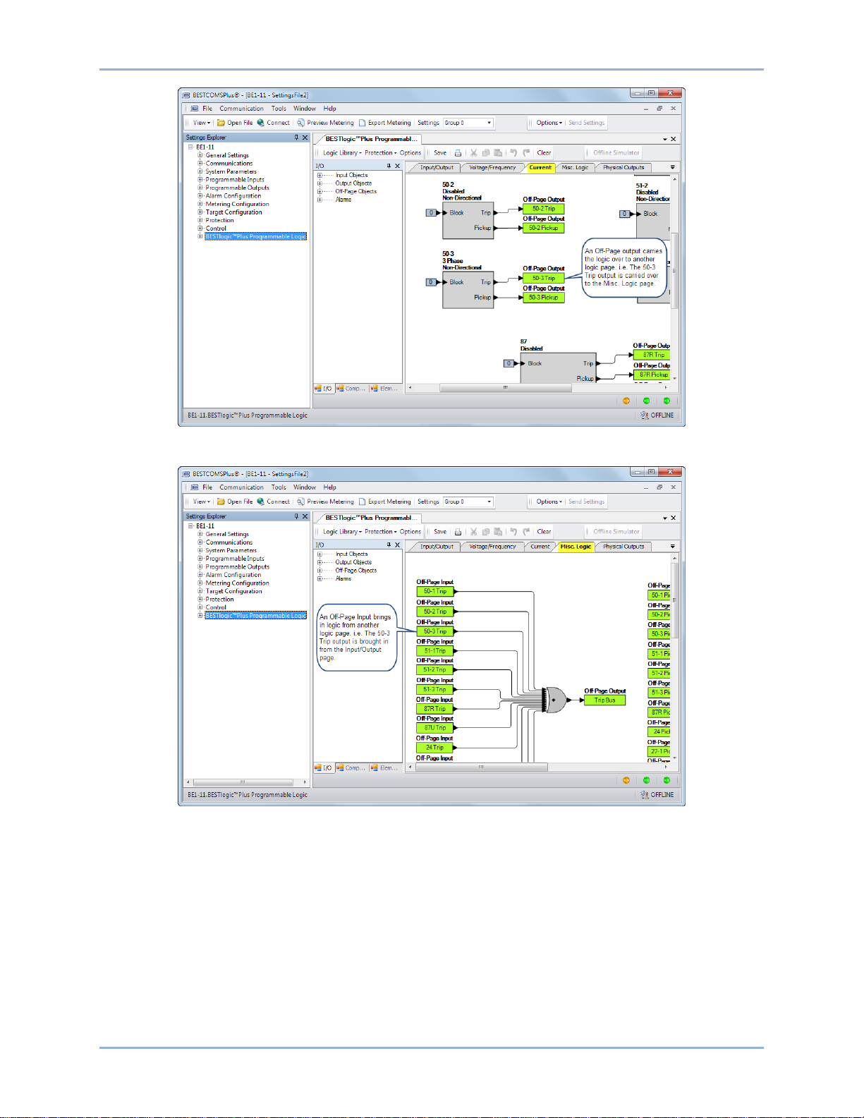
9424200995 Rev H 17
Figure 13. BESTlogicPlus Current Page
Figure 14. BESTlogicPlus Misc. Logic Page
BE1-11t Quick Start
Page 30
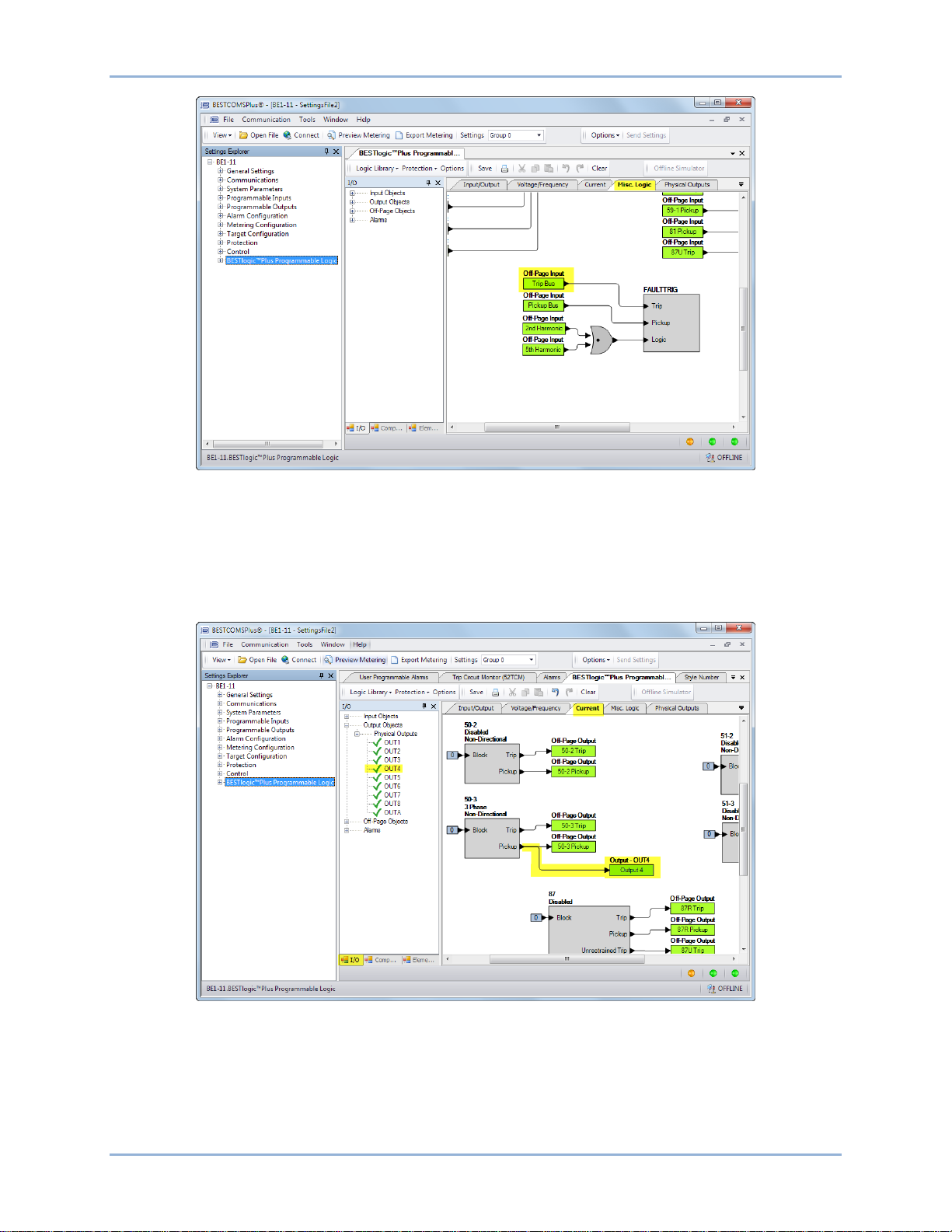
18 9424200995 Rev H
Figure 15. BESTlogicPlus Misc. Logic Page
Step 10: In this step, the Pickup output of the 50-3 element is connected to Output 4. When the Pickup
output of the 50-3 element is true, the label of Output 4 is displayed in the fault report and/or
sequence of events report. The label is named in Step 12. Click the Current tab and then click
the I/O tab at the bottom. Expand Output Objects and then Physical Outputs. Click and drag
OUT4 over to the logic diagram. Click on the Pickup output of the 50-3 element and drag it to the
input of OUT4 to make a connection. Refer to Figure 16.
Figure 16. BESTlogicPlus Programming OUT4
Step 11: In this step, the Pickup output of the 50-3 element is connected to User Alarm 1. When the
Pickup output of the 50-3 element is true, the label of the user alarm is displayed on the Alarms
screen on the front-panel display and in the fault report and/or sequence of events report. The
label is named in Step 13. Click the Current tab and then click the Elements tab at the bottom.
Locate the User Alarm 1 element. Click and drag USERALM1 over to the logic diagram. Click on
Quick Start BE1-11t
Page 31

9424200995 Rev H 19
the Pickup output of the 50-3 element and drag to the input of USERALM1 to make a
connection. Refer to Figure 17.
Figure 17. BESTlogicPlus Programming User Alarm 1
Step 12: Click the Save button to save the logic to BESTCOMSPlus memory for later inclusion in the
settings file. See Figure 18.
Figure 18. BESTlogicPlus Toolbar
Step 13: In the Settings Explorer, expand Programmable Outputs, Contact Outputs, and name Output #4
(50-3 Pickup) as shown in Figure 19.
Step 14: In the Settings Explorer, expand Alarm Configuration, User Programmable Alarms, and name
User Programmable Alarm #1 (50-3 Pickup) as shown in Figure 20.
BE1-11t Quick Start
Page 32

20 9424200995 Rev H
Figure 19. Contact Outputs Screen
Figure 20. User Programmable Alarms Screen
Step 15: Figure 21 shows the user-defined labels of OUT4 and USERALM1 that were named in Step 13
and Step 14.
Quick Start BE1-11t
Page 33

9424200995 Rev H 21
Figure 21. OUT4 and USERALM1 with User-Defined Labels
Step 16: Select Save from the File pull-down menu to save your new settings file.
Step 17: To make your new settings active in the BE1-11t, select Upload Settings and Logic to Device
from the Communication pull-down menu. Enter the username and password.
BE1-11t Quick Start
Page 34

22 9424200995 Rev H
Quick Start BE1-11t
Page 35
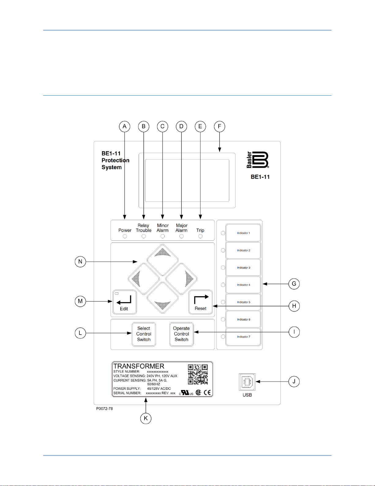
9424200995 Rev H 23
Controls and Indicators
BE1-11t controls and indica tor s are located on the front panel and incl ude sealed membrane switches,
LED (light emitting diode) indicator lamps, and a multiple-line, alphanumeric LCD (liquid crystal display).
Illustrations and Descriptions
The HMI (Human-Mac hine I nterfac e) is illustrated in Figure 22 and described in Table 2. The locators and
descriptions of Table 2 correspond to the locators shown in Figure 22.
Figure 22. Front Panel
BE1-11t Controls and Indicators
Page 36

24 9424200995 Rev H
Locator
Description
A
Power Indicator – This green LED lights when operating power is applied to the BE1-11t.
B
Relay Trouble Indicator – This red LED lights momentarily during start-up and lights
provides a complete description of all BE1-11t failure alarm diagnostics.
C, D
Minor Alarm, Major Alarm Indicators – These red LEDs light to indicate that a programmable
conditions. The Alarms chapter provides detailed information about programming alarms.
E
Trip Indicator – A flashing red Trip LED indicates that a protective element is picked up. A
protective trip has occurred and targets are dis play ed.
F
Display – 64 x 128 dot pixels liquid crystal display (LCD) with backlighting. The LCD is the
displayed in a menu.
G
Indicators – These red LEDs are programmable through BESTlogic™Plus. An indicator label
Indicator status is also available through the Metering Explorer in BESTCOMSPlus®.
H
Reset Pushbutton – Pressing this button resets the Trip LED, sealed-in Trip Targets, Peak
Demand Currents, and Alarms.
I
Operate Control Switch – This pushbutton operates a 43 virtual control switch after it has
chapter for more information about the control switches.
J
USB – This universal serial bus port is used to communicate with the BE1-11t using
BESTCOMSPlus.
K
Identification Label – This label lists the style number, serial number, sensing input current
announcements.
L
Select Control Switch – This pushbutton selects an enabled 43 virtual control switch. The
Virtual Control Switches (43) chapter for more information about the control switches.
M
Edit Pushbutton – Settings changes are made at the front panel using this pushbutton.
Access Error.
N
Scrolling Pushbuttons – Use these four switches to navigate (UP/DOWN/LEFT/RIGHT)
change the variable.
Table 2. Front Panel Descriptions
continuously when a BE1-11t failure is detected. The Contact Inputs and Outputs chapter
alarm has been set. Each indicator can be programmed to annunciate one or more
continuously lit LED indicates that a trip output is closed. This red LED is sealed in if a
primary source for obtaining information from the BE1-11t or when locally setting the
BE1-11t. Information such as targets, metering values, demand values, communication
parameters, and diagnostic information is provided by the LCD. Information and settings are
can be attached next to each LED. Labels of typical system conditions are provided. Refer
to the BESTlogicPlus chapter for information on assigning logic elements to LED indicators.
been selected using the Select Control Switch (L). Refer to the Virtual Control Switches (43)
and voltage range, and power supply input voltages. The QR (Quick Response) code is
read by an imaging device, such as a camera on a mobile phone or tablet. If an internet
connection is available, you will be directed to the BE1-11t mobile web page where you can
access this instruction manual, frequently asked questions, and a basic troubleshooting
guide. You can also contact technical support and subscribe to Basler Electric product email
Operate Control Swit c h (J) operates the switch after it has been selected. Refer to the
When pushed, this switch lights to indicate that Edit mode is active. When you are finished
making settings changes (using the scrolling pushbuttons) and the Edit switch is pressed
again, the switch light turns off to indicate that your settings changes have been saved. If
changes are not completed and saved before the access timeout length setting expires, the
BE1-11t will automatically exit the Edit mode without saving any changes and announce an
through the LCD menu tree. When in Edit mode, the LEFT and RIGHT scrolling
pushbuttons select the variable to be changed. The UP and DOWN scrolling pushbuttons
Controls and Indicators BE1-11t
Page 37

9424200995 Rev H 25
BE1-11t
BE1-11 Menu
Metering
Settings
Metering Explorer
Analog Metering
Status
Reports
Demand Meter
Power Quality
Control
P0069-18
Settings Explorer
General Settings
Communication
System Parameters
Input Contacts
Analog Inputs
RTD Types
Analog Outputs
Alarm Configuration
Metering Configuration
Protection
Control
Logic
TRANSFORMER
PROTECTION SYSTEM
Menu Navigation
A menu tree with a Metering branch and a Settings branch can be accessed through the front-panel
controls and display. A greater level of detail in a menu branch is accessed using the right scrolling
pushbutton. The left scrolling pushbutton is used to return to the top of the menu branch.
Figure 23 illustrates the organization of the front-panel display menu tree structure.
Front Panel Operations
The following paragraphs describe how the front-panel interface is used to set and control BE1-11t
functions.
Entering Usernames and Passwords
If password security has been initiated for a function, the front-panel display will prompt you to enter a
username and password when the Edit pushbutton is pressed. To gain access, you must enter the
appropriate username and password. You can enter usernames and passwords by performing the
following procedure:
BE1-11t Controls and Indicators
Figure 23. Front-Panel Display Menu Tree Layout
1. Press the Edit pushbutton.
2. Enter the username by pressing the UP or DOWN scrolling pushbuttons until the proper first
character of the username appears. Pressing the UP pushbutton scrolls through the alphabet and
then the numbers in ascending order. Pressing DOWN scrolls through the numbers and then the
alphabet in descending order.
3. Press the RIGHT scrolling pushbutton to move the cursor to the next character of the username
and select the appropriate character.
4. Continue the process until the entire username has been spelled out. Press the Edit pushbutton
when finished.
5. Repeat Steps 2 through 4 for the password.
6. Press the Edit pushbutton.
Page 38

26 9424200995 Rev H
7. If the proper username and password have been entered, the screen will flash the type of access
that has been granted. If an incorrect password has been entered, the screen will flash “Read
Access”.
8. Once you gain access, it remains in effect until the access timeout length setting expires. As long
as you continue to press the Edit key for a function for which you have gained access, the fiveminute timer will be refreshed and you will not be prompted for a password.
To close access immediately, press the Reset button while any non-settings screen is displayed. The
BE1-11t should flash “Read Only” on the LCD screen to indicate access through the front panel has been
terminated.
Entering Settings
Settings for protection functions can be edited by using the RIGHT, LEFT, UP, and DOWN front-panel
navigation keys. Navigate to Settings, Protection.
To edit a setting using the manual scrolling pushbuttons, perform the following procedures:
1. After scrolling to the desired settings group and element category, scroll to the screen that
displays the function to be edited.
2. Press the Edit pushbutton to gain access. If password security has been initiated for settings, you
will be prompted to enter the appropriate username and password. See the paragraphs, Entering
Usernames and Passwords , for details on entering usernames and passwords from the front
panel. Once access has been gained, the Edit LED will be lit and a cursor will appear in the first
settings field on the screen.
3. Press the UP or DOWN scrolling key to select the desired setting. Some settings require entering
a number one character at a time. For example, to enter a 51-1 pickup as 7.3 amps, you would
place the cursor in the PU field and press the UP pushbutton until the 7 is showing. Then press
the RIGHT pushbutton to move the cursor over to the right side of the decimal and press the UP
pushbutton until the 3 is showing. Other settings require scrolling through a list of selections. For
example, you would move the cursor over to the CRV field and then scroll through a list of
available TCC curves.
4. Once all of the settings on the screen have been entered, press the Edit pushbutton a second
time and the settings will be validated. If the settings are in range, the Edit LED will go out. If you
want to abort the edit session without changing any settings, press the Reset pushbutton before
you press the Edit pushbutton the second time. The Edit LED will go out.
Performing Control Operations
Control operations can be executed by navigating to Metering, Control. These functions allow you to
control the state of virtual switches, override logic, control the active setting group, and control the state of
output contacts. All of these functions work similarly to the process of entering settings in that you press
the Edit pushbutton for the action to be executed.
To operate the switch, use the following procedure:
1. Use the scrolling pushbuttons to scroll to Metering, Control, Virtual Switches, 43-1.
2. Press the Edit pushbutton to gain access. If password security has been initiated for control
functions, you will be prompted to enter the appropriate username and password. Once access is
gained to the control function, press the Edit pushbutton and the Edit LED will light.
3. Press the UP or DOWN scrolling key to select the new state for the switch. The “PUL” selection
will pulse the state of the switch from its present state to the opposite state for approximately 200
milliseconds. The “SET” selection will set the state of the switch to TRUE. The “RST” selection
will set the state of the switch to FALSE. The allowable states are dependent upon the logic mode
setting for the switch. If the switch is set to Switch mode, only the “SET” and “RST” will function. If
the switch is set to Pulse mode, only the “PUL” selection will function. If the switch is set to
Switch/Pulse mode, any of the selections will function.
Controls and Indicators BE1-11t
Page 39

9424200995 Rev H 27
4. Press the Edit pushbutton a second time and the switch will change to the selected position and
the Edit LED will go out. If you want to abort the editing session without changing any controls,
press the Reset pushbutton before you press the Edit pushbutton the second time. The Edit LED
will go out.
Resetting Functions
The Reset pushbutton is context sensitive. Its function is dependent upon the screen that is presently
being displayed. For example, pressing the Reset key when the Demand screen is displayed will reset the
demands but it will not reset the alarms, etc. It is necessary to scroll through the menu tree to the
appropriate alarm screen to reset an alarm. You are prompted for a username and password when using
the Reset key.
Display Setup
BESTCOMSPlus Navigation Path: Settings Explorer, General Settings, Front Panel HMI
HMI Navigation Path: Settings Explorer, Control, General Settings, Front Panel HMI
The contrast of the front-panel LCD (liquid crystal display) can be adjusted to suit the viewing angle used
or compensate for environmental conditions. When Invert Display is enabled, the display is inverted to
have black letters on a white background.
A power saving feature, referred to as Sleep mode, will dim the front-panel LCD backlight when a frontpanel key is not pressed for more than the user settable time delay. Normal display operation is resumed
when any front-panel button is pressed. Sleep mode is enabled and disabled in BESTCOMSPlus.
When Screen Scrolling is enabled, the front-panel summary screen will scroll through the list of Scrolling
Screen items. The Scroll Time Delay determines the scrolling speed. When this feature is enabled and no
screens are selected, the splash screen is displayed.
Targets and alarms are automatically displayed on the front-panel LCD when they become active if on the
splash screen. After targets and alarms are reset, the BE1-11t returns to the main screen and begins
scrolling if scrolling is enabled. Press the RIGHT navigation key to access the menu when targets and
alarms are being displayed.
The BESTCOMSPlus Front Panel HMI screen is illustrated in Figure 24. Settings are listed in Table 3.
BE1-11t Controls and Indicators
Figure 24. Front-Panel Display Setup Screen
Page 40

28 9424200995 Rev H
Locator
Setting
Range
Increment
Unit
Default
A
LCD Contrast Value
25 to 100
1
percent
50 B Invert Display
Disabled or Enabled
n/a
n/a
Disabled C Sleep Mode
Disabled or Enabled
n/a
n/a
Enabled
D
Sleep Mode Time Delay
1 to 120
1
seconds
1
E
Language Selection
English or Russian
n/a
n/a
English F Enable Scroll
Disabled or Enabled
n/a
n/a
Enabled
G
Scroll Time Delay
1 to 600
1
seconds
3
H
Scrollable Metering Settings
All Metering Screens
n/a
n/a
None
Table 3. Settings for Front-Panel Display
Controls and Indicators BE1-11t
Page 41

9424200995 Rev H 29
Note
Contact Sensing Turn-On Voltage *
Jumper Installed
(Low Position)
Jumper Not Installed
(High Position)
Txx1xxxxxxxxxx
48 Vdc or 125 Vac/dc
26 to 38 Vdc
69 to 100 Vdc
56 to 97 Vac
Txx2xxxxxxxxxx
125/250 Vac/dc
69 to 100 Vdc
56 to 97 Vac
138 to 200 Vdc
112 to 194 Vac
Txx3xxxxxxxxxx
24 Vdc
n/a
Approx. 5 Vdc
Contact Inputs and Outputs
BE1-11t Transformer Protection Systems provide seven contact inputs, eight general-purpose contact
outputs, and one dedicated, fail-safe alarm contact output. Each input and outp ut i s isolated and
terminated at separate terminals. This section describes the function and setup of each input and output.
Contact-Sensing Inputs
Seven contact inputs are availabl e to initiat e BE1-11t protection system actions. Each isolated in put
requires an external wetting voltage. The nominal voltage(s) of the external dc source(s) must fall within
the BE1-11t dc power supply input voltage range. To enhance user flexibility, the BE1-11t protection
system uses wide-range ac/dc power supplies that cover several common control voltage ratings. To
enhance flexibility, the input circuits are designed to respond to voltages at the lower end of the control
voltage range while not overheating at the high end of the control voltage range.
The contact input circuits are polarity sensitive. When an ac wetting voltage is applied, the input signal is
half-wave rectified by the opto-isolator diodes. The contact inputs drive BESTlogic™Plus variables IN1,
IN2, IN3, IN4, IN5, IN6, and IN7. Each contact input is completely programmable so meaningful labels
can be assigned to each input and the logic-high and logic-low states. The BESTlogicPlus chapter
provides more information about using contact inputs in your programmable logic scheme.
Contact-Sensing Input Jumpers
The BE1-11t protection system is delivered with the jumpers in the
HIGH position. Read the following paragraphs before placing the BE111t in service.
Energizing levels for the contact-sensing inputs are jumper selectable for a minimum of approximately 5
Vdc for 24 Vdc nominal sensing voltages, 26 Vdc for 48 Vdc nominal sensing voltages, or 69 Vdc for 125
Vdc nominal sensing voltages. See Table 4 for the contact-sensing turn-on voltages.
Table 4. Contact-Sensing Turn-On Voltages
Style Option Nomina l Input Voltage
* AC voltage ranges are calculated using the default recognition time (4 ms) and debounce time (16 ms).
Each BE1-11t is delivered with the contact-s ens i ng jumper s disconnected for operation in the higher end
of the control voltage range. If the contact-sensing inputs are to be operated at the lower end of the
control voltage range, the jumpers must be installed.
The following paragraphs describe how to locate and remove/change the contact-sens ing input jumper s :
1. Remove the BE1-11t from s erv ice and de-en er gize it.
2. The contact-sensing input jumpers are located behind the rear terminal blocks that are used for
input connections. Using a 7/64” hex tool, remove the rear terminal block(s) associated with the
BE1-11t Contact Inputs and Outputs
Page 42

30 9424200995 Rev H
input(s) that you want to configure. Observe all electrostatic discharge (ESD) precautions when
handling the BE1-11t.
3. Using the input labels on the rear panel as a guide, locate the appropriate jumper terminal block
that is mounted on the circuit board. Each terminal block has two sets of pins. With the jumper as
installed at the factory, one pin should be visible when viewed from the back of the unit. This
configuration allows the inputs to operate at the higher end of the control voltage range. Figure 25
illustrates the location of the contact-sensing jumpers. The jumpers are shown in the HIGH
position.
4. To select operation at the lower end of the control voltage range, install the jumper across the two
pins using needle-nose pliers. Use care when removing and installing each jumper so that no
components are damaged.
5. When all jumpers are positioned for operation in the desired control voltage range, reinstall the
rear terminal block(s).
6. Using a 7/64” hex tool, tighten the screws to 10 in-lbs (1.12 N•m).
Figure 25. Contact-Sensing Jumper Locations
Digital Input Conditioning Function
Status of the contact-sensing inputs is checked every 1 millisecond. User-settable digital contact
recognition and debounce timers condition the signals applied to the inputs. These parameters can be
adjusted to obtain the optimum compromise between speed and security for a specific application. (See
Figure 26.)
If the sampled status of a monitored contact is detected as energized for the recognition time, the logic
variable changes from a de-energized (logic 0 or false) state to an energized (logic 1 or true) state. Once
contact closure is recognized, the logic variable remains in the energized state until the sampled status of
the monitored contact is detected to be de-energized for a period that is longer than the debounce time.
Contact Inputs and Outputs BE1-11t
Page 43

9424200995 Rev H 31
At this point, the logic variable will change from an energized (logic 1 or true) state to a de-energized
(logic 0 or false) state.
Figure 26. Digital Input Conditioning Timing Diagram
Setting the Contact Inputs
BESTCOMSPlus Navigation Path: Settings Explorer, Programmable Inputs, Contact Inputs
HMI Navigation Path: Settings Explorer, Contact Inputs
Settings and labels for the contact inputs are set using BESTCOMSPlus®.
Each of the seven inputs has two settings and three labels. The settings are Recognition Time and
Debounce Time. The labels include a label to describe the input, a label to describe the Energized State,
and a label to describe the De-Energized State. Labels are used by the BE1-11t's reporting functions.
To edit the settings or labels, use the Settings Explorer to open the Pr ogra mm abl e Input s , Contact Inputs
tree branch as shown in Figure 27.
Figure 27. Contact Inputs Screen
BE1-11t Contact Inputs and Outputs
Page 44

32 9424200995 Rev H
Setting
Range
Increment
Unit
Default
Label
User programmable label for the input contact. Used by the reporting function to
characters long.
Recognition Time
4 to 255
1 *
milliseconds
4
Debounce Time
4 to 255
1 *
milliseconds
16
Energized State
User programmable label for the energized state of the contact. Used by the
This label can be up to 64 characters long.
De-Energized
User programmable label for the de-energized state of the contact. Used by the
This label can be up to 64 characters long.
See Table 5 for a list of settings and their defaults.
Table 5. Contact Input Settings
give meaningful identification to the input contact. This label can be up to 64
reporting function to give meaningful identification to the state of the input contact.
State
* Since the input conditioning function is evaluated every quarter cycle, the setting is internally rounded to
the nearest multiple of 4.16 milliseconds (60 Hz systems) or 5 milliseconds (50 Hz systems).
If you are concerned about ac voltage being coupled into the contact sensing circuits, the recognition time
can be set higher than one-half of the power system cycle period. This will take advantage of the halfwave rectification provided by the input circuitry.
If an ac wetting voltage is used, the recognition time can be set to less than one-half of the power system
cycle period and the debounce timer can be set to greater than one-half of the power system cycle period.
The extended debounce time will keep the input energized during the negative half-cycle. The default
settings of 4 and 16 milliseconds are compatible with ac wetting voltages.
Settings for contact inputs can also be entered through the front panel.
See the Terminals and Connectors chapter for an illustration of the programmable output terminals.
Contact output electrical ratings are listed in the Specifications chapter.
reporting function to give meaningful identification to the state of the input contact.
Retrieving Contact-Sensing Input Status
Contact input status is determined through BESTCOMSPlus by using the Metering Explorer to open the
Status, Inputs tree branch. BESTCOMSPlus must be online with the BE1-11t to view contact input status.
Alternately, status can be determined through the front-panel display by navigating to Metering > Status >
Inputs.
Contact Outputs
BE1-11t protection systems have eight general-purpose contact out puts (OUT1 through OUT8) and one
failsafe, normally open or closed (when de-energized) alarm contact output (OUTA). Each output is
isolated and rated for tripping duty. OUT1 through OUT8 are Form A (normally open), and OUTA is Form
B (normally closed) or Form A (normally open).The style number determines the type of alarm contact
output. A trip coil monitoring circuit is hardwired across OUT1. See the Trip Circuit Monitor (52TCM)
chapter for details.
Contact outputs OUT1 through OUT8 and OUTA are driven by BESTlogicPlus expressions for OUT1
through OUT8 and OUTA. The use of each contact output is completely programmable so you can assign
meaningful labels to each output and to the logic 0 and logic 1 states of each output. The BESTlogicPlus
chapter has more information about programming output expressions in your programmable logic
schemes.
BESTlogicPlus expressions for OUT1 through OUT8 and OUTA drive contact outputs OUT1 through
OUT8 and OUTA. The state of the contact outputs can vary from the state of the output logic expressions
for three reasons:
Contact Inputs and Outputs BE1-11t
Page 45
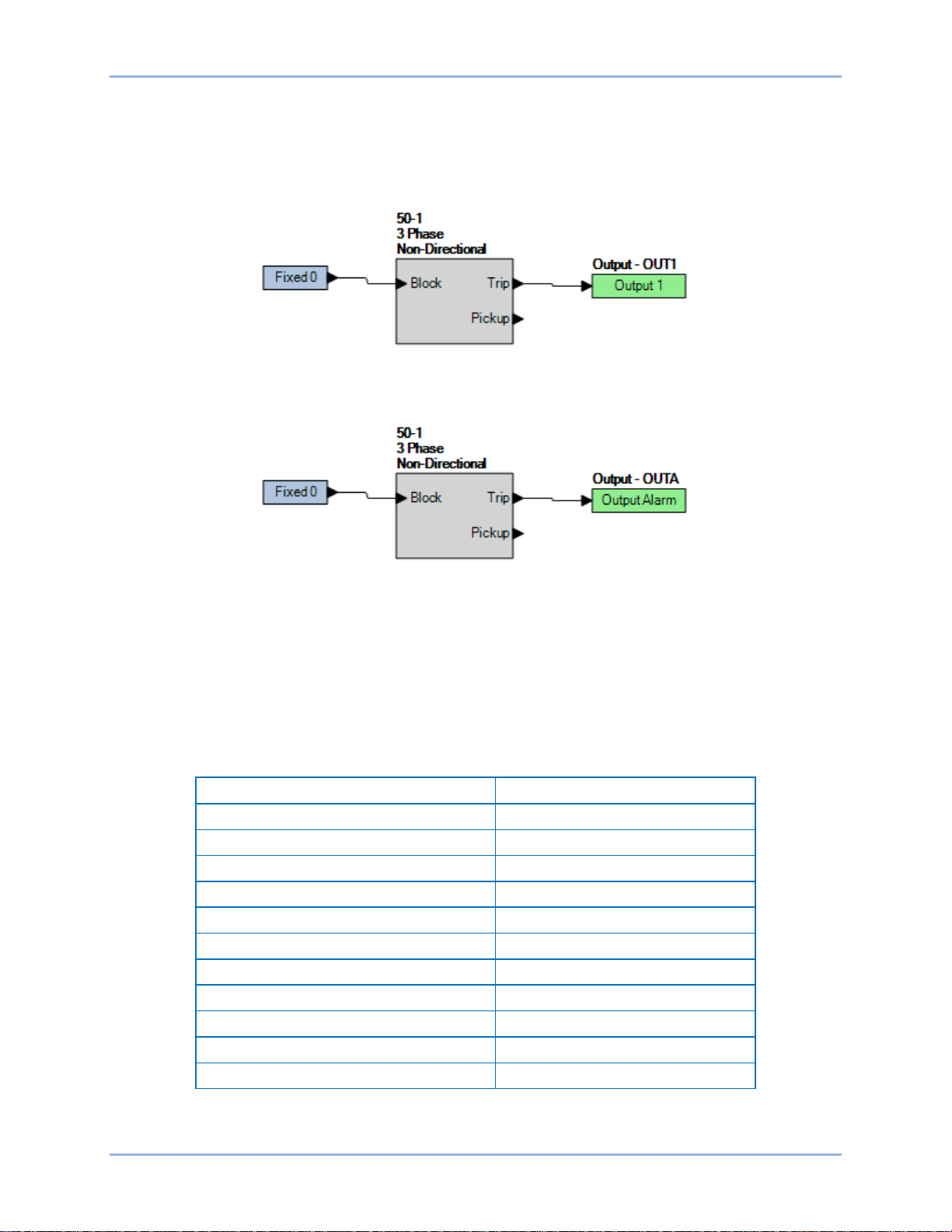
9424200995 Rev H 33
Name
Description
NVMH Settings File Not Opened
Error opening settings file
Update NVM Blocks Failed
Error writing settings file
NVMH Saving Blocks Error
Error writing settings file
NVMH Flash File Error
Error writing settings file
Flash Error
Flash file system error
uP Reset
Repetitive reboot
Cal Error
Calibration error
Cal Defaults Loaded
BE1-11t not calibrated
Defaults Loaded
Defaults have been loaded
uP Overload
Microprocessor is busy
Power Supply
Input power is too low/failed
1. The relay trouble alarm disables all hardware outputs.
2. The programmable hold timer is active.
3. The select-before-operate function overrides a virtual output.
Figure 28 shows a diagram of the contact output logic for the general-purpose contact outputs. The OUT1
relay closes when the 50-1 element is in a trip condition.
Figure 28. Output Logic, General Purpose Contact Outputs
Figure 29 illustrates the contact output logic for the failsafe alarm contact output when OUTA is normally
closed (style xxxxxxx2xxxxxx). The OUTA relay closes when the 50-1 element is in a trip condition.
Figure 29. Output Logic, Failsafe Alarm Contact Output
Relay Trouble Alarm Disable
All internal circuitry and software that affects how the BE1-11t functions is monitored by the continuous
self-test diagnostics function of the relay trouble alarms. A detailed list of relay trouble alarms is provided
in Table 6. If any one of these points asserts, the failsafe alarm output relay de-energizes and
closes/opens (depending on style number) the OUTA contact, the front-panel Relay Trouble LED lights,
all output relays are disabled, logic OUTA is set, and the BE1-11t is taken offline. The relay trouble alarms
function is not programmable.
Table 6. Relay Trouble Alarms
BE1-11t Contact Inputs and Outputs
Page 46

34 9424200995 Rev H
Programmable Hold Timer—Hold Attribute
Historically, electromechanical relays have provided trip contact seal-in circuits. These seal-in circuits
consisted of a dc coil in series with the relay trip contact and a seal-in contact in parallel with the trip
contact. The seal-in feature serves several purposes for electromechanical relays. One purpose is to
provide mechanical energy to drop the target. A second purpose is to carry the dc tripping current from
the induction disk contact, which might not have significant closing torque for a low resistance connection.
A third purpose is to prevent the relay contact from dropping out until the current has been interrupted by
the 52a contacts in series with the trip coil. If the tripping contact opens before the dc current is
interrupted, the contact might be damaged. Of the three items, only item three is an issue for electronic
protection systems like the BE1-11t.
Contact Output Seal-In Logic
To prevent the output relay contacts from opening prematurely, a 200 millisecond hold timer can be
selected with BESTCOMSPlus. If the protection engineer desires seal-in logic with feedback from the
breaker position logic, he/she can provide this logic by modifying the logic for the tripping output. To do
this, use one of the general purpose timers (62) and set it for Pickup/Dropout mode. Set the timer logic so
that it is initiated by the breaker position input and set the timer for two cycles pickup and two cycles
dropout. The same can be done for the closing output. Figure 30 provides a seal-in logic diagram.
Figure 30. Contact Output Seal-In Logic Diagram
Setting the Contact Outputs
BESTCOMSPlus Navigation Path: Settings Explorer, Programmable Outputs, Contact Outputs
HMI Navigation Path: Not available through the fron t pane l
Settings and labels for the contact outputs are set using BESTCOMSPlus.
Each of the eight outputs has one setting and three labels. The setting consists of a Hold Attribute. The
labels include a label to describe the output, a label to describe the Energized State, and a label to
describe the De-Energized Stat e. Labels are used by the BE1-11t's reporting functions.
To edit the settings or labels, use the Settings Explorer to open the Programmable Outputs, Contact
Outputs tree branch as shown in Figure 31.
Contact Inputs and Outputs BE1-11t
Page 47

9424200995 Rev H 35
Figure 31. Contact Outputs Screen
Contact Output Logic Override Control
BESTCOMSPlus Navigation Path: Metering Explorer, Control, Output Override
HMI Navigation Path: Metering Explorer, Control, Output Override Contacts
Each contact output can be controlled directly using the select-before-operate output control function. The
output logic expression that normally controls the state of an output can be overridden and the co ntac t
pulsed, held open, or held closed. This function is useful for testing purposes. An alarm point is available
in the programmable alarm function for monitoring when the output logic has been overridden. See the
Alarms chapter for more information about programmable alarms. Output logic override control is
achieved using the front-panel interface or BEST CO M SPlus. Use the Metering Explorer to open the
Control, Output Override screen. Refer to Figure 32.
Figure 32. Output Override Screen
Enabling Logic Override Contr ol
By default, logic override control is disabled. Output logic override must be enabled before the control can
be used. Enabling of the output logic override control is not possible at the front panel. It can only be
enabled through a communication port using BESTCOMSPlus (Figure 32). Click on the Disabled button
next to the output you want to control. This button will change to Enabled and the follow ing three ac tio n
choices will appear to the right: Reset, Set, and Pulse.
Pulsing a Contact Output
Pulsing BE1-11t outputs provides the user the ability to test the operability of an output without energizing
a measuring or timing element. This feature is useful when testing the protection and control system.
When pulsed, an output changes from the current state (as determi ned by the virt ual out put log ic
expression) to the opposite state for 200 milliseconds. After 200 milliseconds, the output is returned
automatically to logic control.
BE1-11t Contact Inputs and Outputs
Page 48

36 9424200995 Rev H
In the Action column, select Pulse from the drop-down menu and click on the green arrow to the right.
Pulse override control can also be accessed at the Metering > Control > Override Output Cont act s sc reen
of the front-panel display by selecting PUL in the Override State field for the output contact to be pulsed.
Changing the State of a Contact Output
Outputs can be forced to an energized (logic 1 or true) state or to a de-energized (logic 0 or false) state.
This feature can be used to disable a contact during testing.
In the Action column, select Set or Reset from the drop-down menu and click on the green arrow to the
right. Contact output override control can also be accessed at the Metering > Control > Override Output
Contacts screen of the front-panel display by entering a SET (logic 1 or true) or RST (logic 0 or false) in
the Override State field for the contact output to be controlled.
Returning a Contact Output to Logic Control
When the output logic has been overridden and the contact is held in an energized or de-energized state,
it is necessary to return the output to logic control.
Click on the Enabled button next to the output you want to change to logic control. This button changes to
Disabled and the action choices disappear. Logic control can also be achieved at the Metering > Control
> Override Output Contacts screen of the front-panel display by setting Override Enable to Disabled.
See the Terminals and Connectors chapter for an illustration of the programmable output terminals.
Contact output electrical ratings are listed in the Specifications chapter.
Retrieving Contact Output Status
Output status is determined through BESTCOMSPlus by using the Metering Explorer to open the
Status/Outputs tree branch. BESTCOMSPlus must be online with the BE1-11t to view contact output
status. Alternately, status can be determined through the front panel front-panel dis play by navigating to
Metering > Status > Outputs.
Contact Inputs and Outputs BE1-11t
Page 49

9424200995 Rev H 37
Frequency Nominal
3V
V/Hz
Frequency Measured
V Measured
V/Hz
Nominal
Nominal
Phase-Phase
Measured
∗
==
Frequency Nominal
V
V/Hz
Frequency Measured
V
Measured
V/Hz
Nominal
Nominal
-NeutralPhase
Measured
==
Overexcitation (24) Protecti on
The overexcitation (24) element monitors the volts per hertz ratio and protects transformers and
generators from the adverse effects of excessive heating resulting from overexcitation. Overexcitation
exists whenever the per unit volts per hertz exceeds the equipment design limitations.
Element logic connections are made on the BESTlogic™Plus sc reen in BESTCOMSPlus® a nd ele me nt
operational settings are configured on the Overexcitation (24) settings screen in BESTCOMSPlus. A
summary of the logic inputs and outputs and operational settings appears at the end of this chapter.
BESTCOMSPlus Navigation Path: Settings Explorer, Protection, Voltage, Overexcitation (24)
HMI Navigation Path: Settings Explorer, Protection, Settings Group x (where x = 0 to 3), Voltage
Protection, Overexcitation 24
Element Operation
Overexcitation occurs when a generator or transformer magnetic core becomes saturated. When this
happens, stray flux is induced in non-laminated components, causing overheating. The BE1-11t detects
overexcitation conditions with a volts per hertz element that consists of one alarm setting, one inverse
time characteristic with selectable exponents (3 sets of time curves), and two definite-time characteristics.
This allows the user to select an individual inverse-time characteristic, a composite characteristic with
inverse time, and one or two definite-time elements, or a dual-level, definite-time element.
The inverse time characteristic closely approximates the heating characteristic of the protected equipment
as overexcitation increases. A linear reset characteristic provides for the decreasing (cooling) condition.
The overexcitation element responds to the magnitude of voltage versus frequency where the measured
voltage is phase to phase and includes the phase with the frequency measurement element.
Sensing Configuration
The pickup settings determine the V/Hz pickup level. The measured V/Hz is always calculated as the
measured voltage divided by the sensed system frequency. The measured phase depends on the
sensing voltage setting. The 24 element monitors VAB for both 3-wire and 4-wire connections. Thus, the
setting is in VPP/Hz for VT connection = 3W, 4W, AB, BC, CA and VPN/ Hz for VT connect ion = AN, BN,
CN. For more information, refer to the Configuration chapter.
Nominal voltage for the BE1-11t is defined as a phase-to-neutral quantity. Nominal V/Hz depends on the
sensing voltage (VT) connection, nominal voltage, and nominal frequency settings. Nominal V/Hz is
calculated as the nominal voltage divided by nominal frequency. For VT connections equal to 3W, 4W,
AB, BC, CA, the nominal voltage (phase-neutral value) must be converted to a phase-phase value by
multiplying by the square root of 3. No additional conversion is required for VT connections equal to AN,
BN, or CN.
For 3W, 4W, AB, BC, or CA phase to phase sensing connections:
Equation 1. V/Hz Measured (3W, 4W, AB, BC, or CA)
For AN, BN, or CN phase to neutral sensing connections:
Equation 2. V/Hz Measured (AN, BN, or CN)
BE1-11t Overexcitation (24) Protection
Page 50

38 9424200995 Rev H
n
Nominal
Measured
T
T
1
V/Hz
V/Hz
D
T
−
=
100*
FST
E
*DT
T
RR
=
Trip and Reset Equations
Equation 3 and Equation 4 represent the trip time and reset time for a constant V/Hz level. Normally, the
V/Hz pickup is set to a value greater than the V/Hz nominal. This ensures that V/Hz measured divided by
V/Hz nominal is always greater than 1.000 throughout the pickup range. If the pickup is set less than
nominal, then measured values above pickup and below nominal will result in the maximum time delay.
The maximum time delay is determined by Equation 3 with (V/Hz measured / V/Hz nominal) set equal to
1.001. The overall inverse time delay range is limited to 1,000 seconds maximum and 0.2 seconds
minimum.
Equation 3. Time to Trip
Equation 4. Time to Reset
where:
T
= Time to trip
T
T
= Time to reset
R
D
= Time dial trip
T
D
= Time dial, reset
R
E
= Elapsed time
T
n = Curve exponent (0.5, 1, 2)
FST = Full scale trip time (T
E
/FST = Fraction of total travel toward trip that integration had progressed to. (After a trip, this value
T
)
T
will be equal to one.)
Pickup and Trip
The Pickup output occurs first, followed by the Trip output.
Pickup
The Pickup output becomes true when the measured V/Hz increases above the V/Hz threshold
established by the Pickup setting. In BESTlogicPlus, the Pickup output can be connected to other logic
elements to annunciate the condition, con tr ol other el e ments in logic , and start the fault recorder
(FAULTTRIG).
Assertion of the Pickup output initiates an inverse or definite timer that begins timing to a trip. The
duration of the timer is established by the Time Dial (inverse time) or Time Delay (definite time) setting. A
Time Delay or Time Dial setting of zero (0) makes the 24 element instantaneous with no intentional time
delay.
If the monitored V/Hz is above both the calcu lat ed inverse time and definite time delay thresholds, the
definite time delay has priority over the inverse time characteristic.
If the pickup condition subsides before the element delay or calculated inverse time expires, the timer and
Pickup output are reset, no corrective action is taken, and the element is rearmed for any other
occurrences of overexcitation. If inverse reset is chosen, the inverse trip timer will ramp down towards
reset at a linear rate based on the Reset Dial setting. A Reset Dial setting of zero (0) makes the reset
instantaneous with no intention al de lay. See the Time Curve Characteristics chapter for details on each of
the available time curves.
Trip
The Trip output becomes true if an overexcitation pickup condition exists for the duration of the element
Time Delay (definite time) or calculated inverse time. In BESTlogicPlus, the Trip output can be connected
to other logic elements and to a physical relay output to annunciate the condition and to initiate corrective
action. If a target is enabled for the element, the BE1-11t will record a target when the Trip output
becomes true. See the Fault Reporting chapter for more information about target reporting.
Overexcitation (24) Protection BE1-11t
Page 51

9424200995 Rev H 39
Setting
Range
Increment
Unit of Measure
Default
Alarm Pickup
0 or 0.5 to 6
0.01
V/Hz
0
Alarm Time Delay
0 or 50 to 600,000
varies
milliseconds
0
Name
Function
Purpose
Block
Input
Disables the 24 function when true
Trip
Output
True when the 24 element is in trip condition
Pickup
Output
True when the 24 element is in pickup condition
Programmable Alarm
A 24 Volts per Hz alarm occurs during overexcitation so that corrective action can be taken before the 24
function trips. The alarm appears on the front-panel display, web page interface, and on the Alarms
metering screen in BESTCOMSPlus. Refer to the Alarms chapter for information about programming
alarms.
When the Alarm Pickup setting is exceeded, a timer is initiated and begins timing toward a trip. The
duration of the timer is established by the alarm Time Delay setting. An alarm Time Delay setting of zero
(0) makes the alarm instantaneous with no intentional time delay.
If the alarm pickup condition persists for the duration of the alarm Time Delay setting, the 24 Volts per Hz
alarm becomes true. If the alarm pickup condition subsides before the alarm time delay expires, the timer
is reset and no corrective action is taken.
Table 7 lists the programmable alarm settings.
Table 7. Programmable Alarm Settings
Element Blocking
The Block input provides logic-supervision control of the element. When true, the Block input disables the
element by forcing the Trip and Pickup outputs to logic 0 and resetting the element timer. Connect the
element Block input to the desired logic in BESTlogicPlus. When the element is initially selected from the
Elements view, the default condition of the Block input is a logic 0.
Logic Connections
Overexcitation element logic connections are made on the BESTlogicPlus scr een in BESTCOMSPlus.
The overexcitation element logic block is illustrated in Figure 33. Logic inputs and outputs are
summarized in Table 8.
Figure 33. Overexcitation Element Logic Block
Table 8. Logic Inputs and Outputs
Operational Setti ngs
Overexcitation operational settings are configured on the Overexcitation (24) settings screen (Figure 34)
in BESTCOMSPlus. Setting ranges and defaults are summarized in Table 9.
BE1-11t Overexcitation (24) Protection
Page 52

40 9424200995 Rev H
Setting
Range
Increment
Unit of Measure
Default
Mode
Disabled or Enabled
n/a
n/a
Disabled
Pickup (Inverse Time)
0 or 0.5 to 6
0.01
v/Hz
0
Time Dial (Inverse Time)
0 to 9.9
0.1
units
0
Reset Dial (Inverse Time)
0 to 9.9
0.1
units
0
Curve Exponent (Inverse Time)
0.5, 1, or 2
n/a
n/a
1
Pickup (Definite Time 1 & 2)
0 or 0.5 to 6
0.01
v/Hz
0
Time Delay (Definite T i me 1 & 2)
50 to 600,000
varies
milliseconds
50
Note
Figure 34. Overexcitation Settings Screen
Table 9. Operational Settings
Settings Example
The overexcitation element is used to de-energize a generator or transformer that is experiencing an
overexcitation condition. Therefore, the manufacturer's overexcitation limit curves are required to
establish optimum protection. Figure 35 and F i gure 36 show examples of a transformer and generator
limit curve along with the optimum composite protection characteristic.
Overexcitation (24) Protection BE1-11t
Actual damage curves must be obtained from the equipment
manufacturer for the particular equipment to be protected.
Page 53
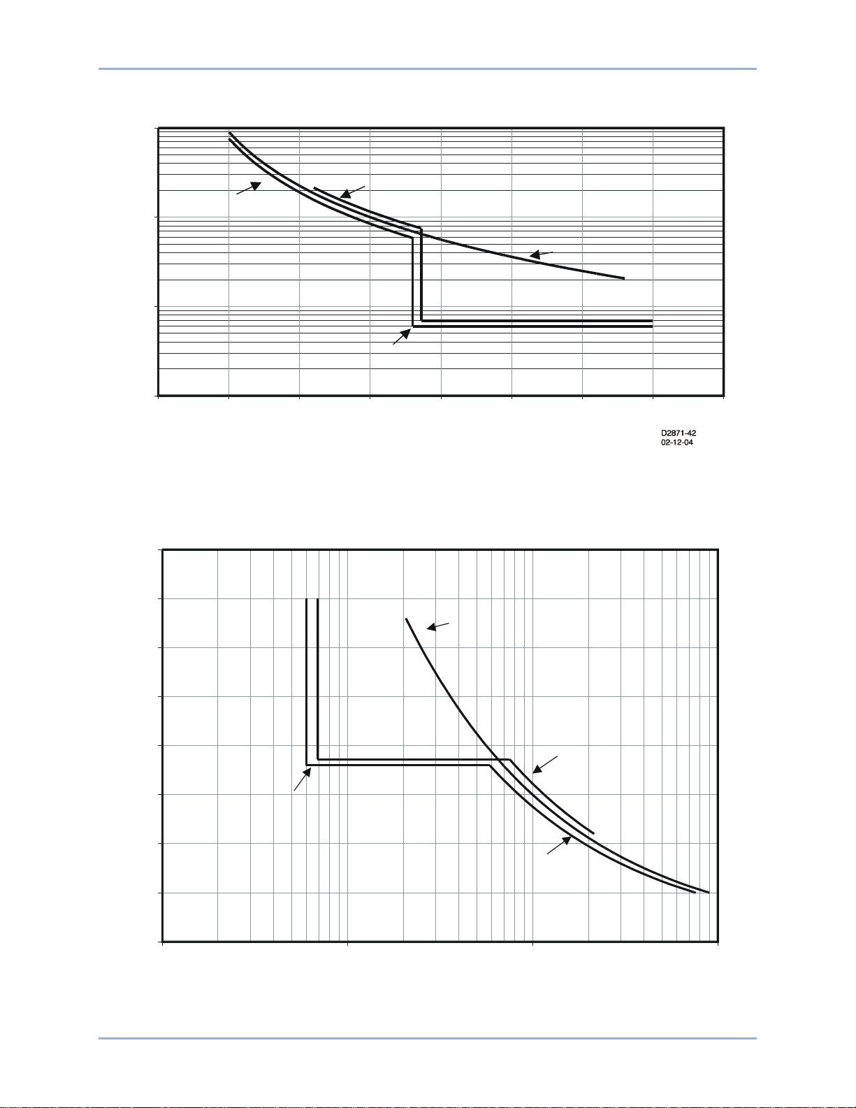
9424200995 Rev H 41
Volt/Hz Characteristic
1.0
10.0
100.0
1000.0
100% 105% 110% 115% 120%
125% 130% 135% 140%
Percent of Nominal V/Hz
Time in Seconds
Transformer Limit
Generator Limit
Inverse
105%, TD=1.9
Definite
118%, 6s
Volt/Hz Characteristic
100%
105%
110%
115%
120%
125%
130%
135%
140%
1.0 10.0 100.0 1000.0
Time in Seconds
Percent of Nominal V
/Hz
Transformer Limit
Generator Limit
Inverse
105%, TD=1.9
Definite
118%, 6s
D2871-43
02-12-04
Figure 35. Time Shown on Vertical Axis
BE1-11t Overexcitation (24) Protection
Figure 36. Time Shown on Horizontal Axis
Page 54

42 9424200995 Rev H
seconds300100
50
30
0.5T100
FST
E
DT
R
T
RR
=∗∗=∗∗=
Assuming a Vnom of 69.3 Vpn, 1 pu volts/hertz = (69.3 * √3) / 60 = 2.00. Using IEEE Std C37.102-2006 -
IEEE Guide for AC Generator Protection as a guide for setting overexcitation protection, the following
example demonstrates how to set the BE1-11t to provide a composite V/Hz characteristic for protection of
a generator and a step-up transformer:
• Alarm = 105% @ 1 second time delay; V/Hz = 2 * 1.05 = 2.10
• Inverse time pickup = 105%; Time Dial = 1.9; Inverse Trip Curve = (M-1)^2; V/Hz = 2 * 1.05 = 2.10
• Definite Time #1 = 118% @ 6 seconds time delay; V/Hz = 1.18 * 2.0 = 2.36
The reset rate is determined by the Reset Dial setting. A setting of zero (0) gives an instantaneous reset.
Using the inverse squared characteristic, assume a trip time dial setting 2.0 and a pickup multiple of 1.2.
The total time to trip will be 50 seconds. If this exists for 30 seconds before being corrected (60% elapsed
time), what would the total reset time be for a reset dial setting of 5? Based on the reset equation
(Equation 5), the calculation will be:
Equation 5. Time to Reset
If the overexcitation condition returns prior to total reset (i.e., less than 300 seconds), timing resumes from
that point at the inverse square rate. For example, if this condition recurs after 150 seconds or 50% of the
total reset time, then trip time from the second event will start at 30% instead of 0%, therefore tripping in
70% of the original trip time or 35 seconds. Figure 37 illustrates the inverse time delay and reset time.
Figure 37. Inverse Time Delay and Reset Time
Overexcitation (24) Protection BE1-11t
Page 55

9424200995 Rev H 43
Phase Undervoltage (27P) Protection
Five phase undervoltage (27P) elements monitor the sensing voltage applied to the BE1-11t. An element
can be configured to protect against undervoltage when the phase voltage decreases below a defined
level.
The five, identical phase undervoltage pr otec t ion elements are designated 27P-1, 27P-2, 27P-3, 27P-4,
and 27P-5. Element logic connections are made on the BESTlogic™Plus screen in BESTCOMSPlus® and
element operational settings are configured on the Undervoltage settings screen in BESTCOMSPlus. A
summary of the logic inputs and outputs and operational settings appears at the end of this chapter.
BESTCOMSPlus Navigation Path: Settings Explorer, Protection, Voltage, Undervoltage (27P)
HMI Navigation Path: Settings Explorer, Protection, Settings Group x (where x = 0 to 3), Voltage
Protection, Undervoltage 27P
Element Operation
Phase undervoltage protection can be used to prevent large transformer and equipment damage when an
undervoltage condition exists. For example, an undervoltage condition could occur when a tap changing
control fails.
Modes of Protection
Three modes of protection are available. The One of Three mode activates protection when one of the
three phases of voltage decreases below the Pickup setting. The Two of Three mode activates protection
when any two of the three phases of voltage decrease below the Pickup setting. The Three of Three
mode activates protection when all three phases of voltage decrease below the Pickup setting.
Voltage Response
The phase undervoltage element can be set to monitor VPP or VPN. This is determined by the 27/59
Mode parameter of the phase VT connections found on the System Parameters/Sensing Transformers
settings screen in BESTCOMSPlus. For more information on the VTP setup for PP or PN voltage
response, see the Configuration chapter.
Timings
The timing mode can be set for definite or inverse. For details on the inverse time curve, refer to the Time
Curve Characteristics chapter.
Pickup and Trip
The Pickup output occurs first, followed by the Trip output.
Pickup
The Pickup output becomes true when the measured voltage decreases below the voltage threshold
established by the Pickup setting. In BESTlogicPlus, the Pickup output can be connected to other logic
elements to annunciate the condition, control other elements in logic, and start the fault recorder (logic
element FAULTTRIG).
Assertion of the Pickup output initiates a timer that begins timing to a trip. The duration of the timer is
established by the Time Delay (definite timing) or Time Dial (inverse timing). A Time Delay or Time Dial
setting of zero (0) makes the 27P element instantaneous with no intent ion al tim e delay .
If the pickup condition subsides before the element delay or calculated inverse time expires, the timer and
Pickup output are reset, no corrective action is taken, and the element is rearmed for any other
occurrences of undervoltage.
BE1-11t Phase Undervoltage (27P) Protec t ion
Page 56

44 9424200995 Rev H
Name
Logic Function
Purpose
Block
Input
Disables the 27P func ti on when true
Trip
Output
True when the 27P element is in a trip condition
Pickup
Output
True when the 27P element is in a pickup condition
Trip
The Trip output becomes true when an undervoltage pickup condition persists for the duration of the
element Time Delay setting or calculated inverse time. In BESTlogicPlus, the Trip output can be
connected to other logic elements and to a physical relay output to annunciate the condition and to initiate
corrective action. If a target is enabled for the element, the BE1-11t will record a target when the Trip
output becomes true. See the Fault Reporting chapter for more information about target reporting.
Voltage Inhibit
The Voltage Inhibit setting impedes phase undervoltage element operation during undervoltage
conditions that may occur during equipment startup. This setting is expressed in primary or secondary
voltage depending on the Settings Display Mode selected on the General Settings/Display Units settings
screen in BESTCOMSPlus. Its unit of measure depends upon the phase VT connection setting. For fourwire or phase-to-neutral sensing connections, the inhibit level is expressed in Vpn. For three-wire or
phase-to-phase sensing connections the inhibit level is expressed in Vpp.
Element Blocking
Fuse Loss
The fuse loss (60FL) element of the BE1-11t can be used to block 27P protection when fuse loss or loss
of potential is detected in a three-phase system.
If the 60FL element trip logic is true and Block Phase/V1 is enabled, all functions that use the phase
voltage are blocked. See the Fuse Loss (60FL) chapter for more information on the 60FL function.
Protective elements blocked by 60FL should be set so that trip times are 60 milliseconds or greater to
assure proper coordination of blocking.
Block Logic Input
The Block input provides logic-supervision control of the element. When true, the Block input disables the
element by forcing the Trip and Pickup outputs to logic 0 and resetting the element timer. Connect the
element Block input to the desired logic in BESTlogicPlus. When the element is initially selected from the
Elements view, the default condition of the Block input is a logic 0.
Logic Connections
Phase undervoltage element logic connections are made on the BESTlogicPlus screen in
BESTCOMSPlus. The phase undervoltage element logic block is illustrated in Figure 38. Logic inputs and
outputs are summarized in Table 10.
Figure 38. Phase Undervoltage Element Logic Block
Table 10. Logic Inputs and Outputs
Phase Undervoltage (27P) Protec t ion BE1-11t
Page 57

9424200995 Rev H 45
Setting
Range
Increment
Unit of Measure
Default
Disabled,
or Three of Three
Pickup
0 or 1 to 300
0.1
volts
0
Inhibit Level
0 or 1 to 300
0.1
volts
0
Timing Mode
Definite or Inverse
n/a
n/a
Definite
Time Delay (Definite Timing)
50 to 600,000
varies
milliseconds
50
Time Dial (Inverse Timing)
0 to 9.9
0.1
units
0
Operational Setti ngs
Phase undervoltage element operational settings are configured on the Undervoltage (27P) settings
screen (Figure 39) in BESTCOMSPlus. Set ting ran ges and defa ults are sum mar iz ed in Table 11.
Figure 39. Phase Undervoltage Settings Screen
Mode
Table 11. Operational Settings
One of Three,
Two of Three,
n/a n/a Disabled
BE1-11t Phase Undervoltage (27P) Protec t ion
Page 58

46 9424200995 Rev H
Phase Undervoltage (27P) Protec t ion BE1-11t
Page 59

9424200995 Rev H 47
Auxiliary Undervoltage (27X) Protection
Four auxiliary undervoltage (27X) elements monitor the phase and auxiliary voltage applied to the
BE1-11t. An element can be configured to protect against undervoltage by monitoring neutral-shift
voltage, positive-sequence voltage, negative-sequence voltage, fundamental voltage on the Vx input, or
third-harmonic voltage on the Vx input.
The four, identical auxiliary undervoltage protection elements are designated 27X-1, 27X-2, 27X-3, and
27X-4. Element logic connections are made on the BESTlogic™Plus screen in BESTCOMSPlus® and
element operational settings are configured on the Undervoltage (27X) settings screen in
BESTCOMSPlus. A summary of the logic inputs and outputs and operational settings appears at the end
of this chapter.
BESTCOMSPlus Navigation Path: Settings Explorer, Protection, Voltage, Undervoltage (27X)
HMI Navigation Path: Settings Explorer, Protection, Settings Group x (where x = 0 to 3), Voltage
Protection, Undervoltage 27X
Element Operation
Auxiliary undervoltage protection can be used to protect equipment from damage caused by phase
failure, positive/negative phase sequence, or phase unbalance.
Modes of Protection
Five modes of protection are available: 3V0, V1, V2, Vx Fundamental, and Vx Third Harmonic.
3V0 Mode
3V0 mode provides voltage unbalance protection in a three-phase system. The 3V0 measurement
increases as the three-phase voltages become unbalanced.
V1 Mode
V1 mode provides positive phase-sequence protection in a three-phase system. The V1 measurement
increases as the phase sequence is brought forward.
V2 Mode
V2 mode provides negative phase-sequence protection in a three-phase system. The V2 measurement
increases as voltage becomes unbalanced or the phase sequence is reversed.
Vx Fundamental Mode
Vx Fundamental mode provides ground offset detection on high impedance ground systems or phase
undervoltage protection in s ync -check applications.
Vx Third Harmonic Mode
Vx Third Harmonic mode provides internal generator short detection.
Connections
Connections are made on the rear of the BE1-11t. The phase VT inputs (Va, Vb, Vc) are used when 3V0,
V1, or V2 mode is selected. The auxiliary VT input (Vx) is used when Vx Fundamental or Vx Third
Harmonic mode is selected. For an illustration of terminals, refer to the Terminals and Connectors
chapter.
Sensing Configuration
When using the Vx input, setting the Aux VT Connection parameter provides the correct labeling of
settings and metering data found in BESTCOMSPlus and fault reports. The Aux VT Connection
BE1-11t Auxiliary Undervoltage (27X) Protection
Page 60

48 9424200995 Rev H
Aux VT Connection
Mode
Unit
AB, BC, CA
Vx Fundamental, Vx Third Harmonic
VPP
AN, BN, CN
Vx Fundamental, Vx Third Harmonic
VPN
Ground
Vx Fundamental, Vx Third Harmonic
VPN
Any
V1, V2, and 3V0
VPN
parameter set to AB, for example, will display the metering data as AB in fault records and display the
pickup setting as Vpp in BESTCOMSPlus. See Table 12 for a full list of possible settings. The Aux VT
Connection parameter is found on the System Parameters/Sensing Transformers settings screen in
BESTCOMSPlus. For more information on the auxiliary VT setup, see the Configuration chapter.
Table 12. Auxiliary VT Configuration
Timings
The timing mode can be set for definite or inverse. For details on the inverse time curve, refer to the Time
Curve Characteristics chapter.
Pickup and Trip
The Pickup output occurs first, followed by the Trip output.
Pickup
The Pickup output becomes true when the measured voltage decreases below the voltage threshold
established by the Pickup setting. In BESTlogicPlus, the Pickup output can be connected to other logic
elements to annunciate the condition, control other elements in logic, and start the fault recorder (logic
element FAULTTRIG).
Assertion of the Pickup output initiates a timer that begins timing to a trip. The duration of the timer is
established by the Time Delay (definite timing) or Time Dial (inverse timing). A Time Delay or Time Dial
setting of zero (0) makes the 27X element instantaneous with no intentional time delay.
If the pickup condition subsides before the element delay or calculated inverse time expires, the timer and
Pickup output are reset, no corrective action is taken, and the element is rearmed for any other
occurrences of undervoltage.
Trip
The Trip output becomes true if an undervoltage pickup condition persists for the duration of the element
Time Delay setting or calculated inverse time. In BESTlogicPlus, the Trip output can be connected to
other logic elements and to a physical relay output to annunciate the condition and to initiate corrective
action. If a target is enabled for the element, the BE1-11t will record a target when the Trip output
becomes true. See the Fault Reporting chapter for more information about target reporting.
Voltage Inhibit
The Voltage Inhibit setting impedes auxiliary undervoltage element operation during undervoltage
conditions that may occur during equipment startup. This setting is expressed in primary or secondary
voltage depending on the Settings Display Mode selected on the General Settings/Display Units settings
screen in BESTCOMSPlus.
Its unit of measure depends upon the auxiliary VT connection setting and 27X element mode selected.
For AB, BC, and CA sensing connections in Vx Fundamental or Vx Third Harmonic mode, the inhibit level
is expressed in Vpp. For AN, BN, CN, or Ground sensing connections in Vx Fundamental or Vx Third
Harmonic mode, the inhibit level is expressed in Vpn. The inhibit level is always expressed in Vpn for V1,
V2, and 3V0 modes of the 27X element.
Auxiliary Undervoltage (27X) Protection BE1-11t
Page 61

9424200995 Rev H 49
Name
Logic Function
Purpose
Block
Input
Disables the 27X function when true
Trip
Output
True when the 27X element is in a trip condition
Pickup
Output
True when the 27X element is in a pickup condition
Element Blocking
Fuse Loss
The fuse loss (60FL) element of the BE1-11t can be used to block 27X protection when fuse loss or loss
of potential is detected in a three-phase system.
If the 60FL element trip logic is true and Block Phase/V1 is enabled, the 27X function will be blocked
when configured for V1 mode. If Block V2 is enabled, the 27X function will be blocked when configured
for V2 mode. If Block 3V0 is enabled, the 27X function will be blocked when configured for 3V0 mode.
See the Fuse Loss (60FL) chapter for more information on the 60FL function.
Protective elements blocked by 60FL should be set so that trip times are 60 milliseconds or greater to
assure proper coordination of blocking.
Block Logic Input
The Block input provides logic-supervision control of the element. When true, the Block input disables the
element by forcing the Trip and Pickup outputs to logic 0 and resetting the element timer. Connect the
element Block input to the desired logic in BEST logicPlus. When the element is initially selected from the
Elements view, the default condition of the Block input is a logic 0.
Logic Connections
Auxiliary undervoltage element logic connections are made on the BESTlogicPlus screen in
BESTCOMSPlus. The auxiliary undervoltage element logic block is illustrated in Figure 40. Logic inputs
and outputs are summarized in Table 13.
Figure 40. Auxiliary Undervoltage Element Logic Block
Table 13. Logic Inputs and Outputs
Operational Setti ngs
Auxiliary undervoltage element operational settings are configured on the Undervoltage (27X) settings
screen (Figure 41) in BESTCOMSPlus. Setting ranges and defaults are sum marized in Table 14.
BE1-11t Auxiliary Undervoltage (27X) Protection
Page 62

50 9424200995 Rev H
Setting
Range
Increment
Unit of Measure
Default
Disabled,
Vx Third Harmonic
Pickup
0 or 1 to 150
0.1
volts
0
Inhibit Level
0 or 1 to 150
0.1
volts
0
Timing Mode
Definite or Inverse
n/a
n/a
Definite
Time Delay (Definite Timing)
50 to 600,000
varies
milliseconds
50
Time Dial (Inverse Timing)
0 to 9.9
0.1
units
0
Figure 41. Auxiliary Undervoltage Settings Screen
Table 14. Operational Settings
Mode*
3V0, V1, V2,
Vx Fundamental,
n/a n/a Disabled
* To use 3V0, V1, or V2, the VTP connection cannot be single-phase.
Auxiliary Undervoltage (27X) Protection BE1-11t
Page 63

9424200995 Rev H 51
Negative-Sequence Voltage (47) Protection
Negative-sequence voltage protection is included as a mode of the 27X (Auxiliary Undervoltage) and 59X
(Auxiliary Overvoltage) elements. Refer to the Auxiliary Undervoltage (27X) Protection and Auxiliary
Overvoltage (59X) Protection chapters for information on how to set up and program the V2 (negative-
sequence voltage) mode of the 27X and 59X elements.
Negative-sequence voltage protection is used to sense power-system imbalance. This situation occurs
when a large single-phase load is switched onto the system, or when transformer-input fus es blow in only
one or two phases. Negative-sequence voltage protection is good for detecting improper phasing when
an oncoming generator is paralleled to the power system. All motor loads should be protected from the
heating caused by unbalanced voltage (either on the bus or on each motor feeder). Industry standards
state that the existence of unbalanced voltage feed results in 4 to 10 times the current imbalance. For a
motor feeder, the negative-sequence voltage unbalances should not exceed 5 percent to avoid
overheating and damage.
BE1-11t Negative-Sequence Voltage (47) Protection
Page 64

52 9424200995 Rev H
Negative-Sequence Voltage (47) Protection BE1-11t
Page 65

9424200995 Rev H 53
Phase Overvoltage (59P) Protection
Four phase overvoltage (59P) elements monitor the sensing voltage applied to the BE1-11t. An element
can be configured to protect against overvoltage when the phase voltage increases above a defined level.
The four, identical overvoltage protection elements are designated 59P-1, 59P-2, 59P-3, and 59P-4.
Element logic connections are made on the BESTlogic™Plus sc reen in BESTCOMSPlus® a nd ele me nt
operational settings are configured on the Overvoltage settings screen in BESTCOMSPlus. A summary of
the logic inputs and outputs and operational settings appears at the end of this chapter.
BESTCOMSPlus Navigation Path: Settings Explorer, Protection, Voltage, Overvoltage (59P)
HMI Navigation Path: Settings Explorer, Protection, Settings Group x (where x = 0 to 3), Voltage
Protection, Overvoltage 59P
Element Operation
Overvoltage protection can be used to prevent large transformer and equipment damage when an
overvoltage condition exists. For example, an overvoltage condition could occur when the tap changing
control fails.
Modes of Protection
Three modes of protection are available. The One of Three mode activates protection when one of the
three phases of volt age inc r eas es above the Pickup setting. The Two of Three mode activates protection
when any two of the three phases of voltage increases above the Pickup setting. The Three of Three
mode activates protection when all three phases of voltage increase above the Pickup setting.
Voltage Response
The overvoltage element can be set to monitor VPP or VPN. This is determined by the 27/59 Mode
parameter of the phase VT connections found on the System Parameters/Sensing Transformers settings
screen in BESTCOMSPlus. For more information on the VTP setup for PP or PN voltage response, see
the Configuration chapter.
Timings
The timing mode can be set for definite or inverse. For details on the inverse time curve, refer to the Time
Curve Characteristics chapter.
Pickup and Trip
The Pickup output occurs first, followed by the Trip output.
Pickup
The Pickup output becomes true when the measured voltage increases above the voltage threshold
established by the Pickup setting. In BESTlogicPlus, the Pickup output can be c on nec ted to other log ic
elements to annunciate the condition, con tr ol other el e ments in logic , and start the fault recorder (logic
element FAULTTRIG).
Assertion of the Pickup output initiates a timer that begins timing to a trip. The duration of the timer is
established by the Time Delay (definite timing) or Time Dial (inverse timing). A Time Delay or Time Dial
setting of zero (0) makes the 59P element instantaneous with no intentional time delay.
If the pickup condition subsides before the element delay or calculated inverse time expires, the timer and
Pickup output are reset, no corrective action is taken, and the element is rearmed for any other
occurrences of overvoltage.
BE1-11t Phase Overvoltage (59P) Protection
Page 66

54 9424200995 Rev H
Name
Logic Function
Purpose
Block
Input
Disables the 59P function when true
Trip
Output
True when the 59P element is in a trip condition
Pickup
Output
True when the 59P element is in a pickup condition
Trip
The Trip output becomes true if an overvoltage pickup condition persists for the duration of the element
Time Delay setting or calculated inverse time. In BESTlogicPlus, the Trip output can be connected to
other logic elements and to a physical relay output to annunciate the condition and to initiate corrective
action. If a target is enabled for the element, the BE1-11t will record a target when the Trip output
becomes true. See the Fault Reporting chapter for more information about target reporting.
Element Blocking
Fuse Loss
The fuse loss (60FL) element of the BE1-11t can be used to block 59P protection when fuse loss or loss
of potential is detected in a three-phase system.
If the 60FL element trip logic is true and Block Phase/V1 is enabled, all functions that use the phase
voltage are blocked. See the Fuse Loss (60FL) chapter for more information on the 60FL function.
Protective elements blocked by 60FL should be set so that trip times are 60 milliseconds or greater to
assure proper coordination of blocking.
Block Logic Input
The Block input provides logic-supervision control of the element. When true, the Block input disables the
element by forcing the Trip and Pickup outputs to logic 0 and resetting the element timer. Connect the
element Block input to the desired logic in BESTlogicPlus. When the element is initially selected from the
Elements view, the default condition of the Block input is a logic 0.
Logic Connections
Overvoltage element logic connections are made on the BESTlogicPlus screen i n BESTCOMSPlus. The
overvoltage element logic block is illustrated in Figure 42. Logic inputs and outputs are summarized in
Table 15.
Figure 42. Overvoltage Element Logic Block
Table 15. Logic Inputs and Outputs
Operational Setti ngs
Overvoltage element operational settings are configured on the Overvoltage settings screen (Figure 43) in
BESTCOMSPlus. Setting ranges and defaults are summarized in Table 16.
Phase Overvoltage (59P) Protection BE1-11t
Page 67

9424200995 Rev H 55
Setting
Range
Increment
Unit of Measure
Default
Disabled,
or Three of Three
Pickup
0 or 1 to 300
0.1
volts 0 Timing Mode
Definite or Inverse
n/a
n/a
Definite
Time Delay (Definite Timing)
50 to 600,000
varies
milliseconds
50
Time Dial (Inverse Timing)
0 to 9.9
0.1
units
0
Figure 43. Overvoltage Settings Screen
Mode
Table 16. Operational Settings
One of Three,
Two of Three,
n/a n/a Disabled
BE1-11t Phase Overvoltage (59P) Protection
Page 68

56 9424200995 Rev H
Phase Overvoltage (59P) Protection BE1-11t
Page 69

9424200995 Rev H 57
Auxiliary Overvoltage (59X) Protect i on
Four auxiliary overvoltage (59X) elements monitor the phase and auxiliary voltage applied to the BE1-11t.
An element can be configured to protect against ov erv olta ge by monitoring neutral-shift voltage, positivesequence voltage, negative-sequence voltage, fundamental voltage on the Vx input, or third-harmonic
voltage on the Vx input.
The four, identical auxiliary overvoltage protection elements are designated 59X-1, 59X-2, 59X-3, and
59X-4. Element logic connections are made on the BESTlogic™Plus screen in BESTCOMSPlus® and
element operational settings are configured on the Overvoltage (59X) settings screen in BESTCOMSPlus.
A summary of the logic inputs and outputs and operational settings appears at the end of this chapter.
BESTCOMSPlus Navigation Path: Settings Explorer, Protection, Voltage, Overvoltage (59X)
HMI Navigation Path: Settings Explorer, Protection, Settings Group x (where x = 0 to 3), Voltage
Protection, Overvoltage 59X
Element Operation
Auxiliary overvoltage protection can be used to protect equipment from damage caused by phase failure,
positive/negative phase sequence, or phase unbalance.
Modes of Protection
Five modes of protection are available: 3V0, V1, V2, Vx Fundamental, and Vx Third Harmonic.
3V0 Mode
3V0 mode provides voltage unbalance protection in a three-phase system. The 3V0 measurement
increases as the three-phase voltages become unbalanced.
V1 Mode
V1 mode provides positive phase-sequ ence pr otec t ion in a three-phase system. The V1 measurement
increases as the phase sequence is brought forward.
V2 Mode
V2 mode provides negative phase-sequence pr otection in a three-phase system. The V2 measurement
increases as voltage becomes unbalanced or the phase sequence is reversed.
Vx Fundamental Mode
Vx Fundamental mode provides ground offset detection on high impedance ground systems or phase
overvoltage protection in sync-check applications.
Vx Third Harmonic Mode
Vx Third Harmonic mode detects an increase in third harmonic.
Connections
Connections are made on the rear of the BE1-11t. The phase VT inputs (Va, Vb, Vc) are used when 3V0,
V1, or V2 mode is selected. The auxiliary VT input (Vx) is used when Vx Fundamental or Vx Third
Harmonic mode is selected. For an illustration of terminals, refer to the Terminals and Connectors
chapter.
Sensing Configuration
When using the Vx input, setting the Aux VT Connection parameter provides the correct labeling of
settings and metering data found in BESTCOMSPlus and fault reports. The Aux VT Connection
parameter set to AB, for example, will display the metering data as AB in fault records and display the
BE1-11t Auxiliary Overvoltage (59X) Protection
Page 70

58 9424200995 Rev H
Aux VT Connection
Mode
Unit
AB, BC, CA
Vx Fundamental, Vx Third Harmonic
VPP
AN, BN, CN
Vx Fundamental, Vx Third Harmonic
VPN
Ground
Vx Fundamental, Vx Third Harmonic
VPN
Any
V1, V2, and 3V0
VPN
pickup setting as Vpp in BESTCOMSPlus. See Table 17 for a full list of possible settings. The Aux VT
Connection parameter is found on the System Parameters/Sensing Transformers settings screen in
BESTCOMSPlus. For more information on the auxiliary VT setup, see the Configuration chapter.
Table 17. Auxiliary VT Configuration
Timings
The timing mode can be set for definite or inverse. For details on the inverse time curve, refer to the Time
Curve Characteristics chapter.
Pickup and Trip
The Pickup output occurs first, followed by the Trip output.
Pickup
The Pickup output becomes true when the measured voltage increases above the voltage threshold
established by the Pickup setting. In BESTlogicPlus, the Pickup output can be connected to other logic
elements to annunciate the condition, con tr ol other el e ments in logic , and start the fault recorder (logic
element FAULTTRIG).
Assertion of the Pickup output initiates a timer that begins timing to a trip. The duration of the timer is
established by the Time Delay (definite timing) or Time Dial (inverse timing). A Time Delay or Time Dial
setting of zero (0) makes the 59X element instantaneous with no intentional time delay.
If the pickup condition subsides before the element delay or calculated inverse time expires, the timer and
Pickup output are reset, no corrective action is taken, and the element is rearmed for any other
occurrences of overvoltage.
Trip
The Trip output becomes true if an overvolt age pick up c ondit ion pers ists for the du ration of the eleme nt
Time Delay setting or calculated inverse time. In BESTlogicPlus, the Trip output can be connected to
other logic elements and to a physical relay output to annunciate the condition and to initiate corrective
action. If a target is enabled for the element, the BE1-11t will record a target when the Trip output
becomes true. See the Fault Reporting chapter for more information about target reporting.
Element Blocking
Fuse Loss
The fuse loss (60FL) element of the BE1-11t can be used to block 59X protection when fuse loss or loss
of potential is detected in a three-phase system.
If the 60FL element trip logic is true and Block Phase/V1 is enabled, the 59X function will be blocked
when configured for V1 mode. If Block V2 is enabled, the 59X function will be blocked when configured
for V2 mode. If Block 3V0 is enabled, the 59X function will be blocked when configured for 3V0 mode.
See the Fuse Loss (60FL) chapter for more information on the 60FL function.
Protective elements blocked by 60FL should be set so that trip times are 60 milliseconds or greater to
assure proper coordination of blocking.
Block Logic Input
The Block input provides logic-supervision control of the element. When true, the Block input disables the
element by forcing the Trip and Pickup outputs to logic 0 and resetting the element timer. Connect the
Auxiliary Overvoltage (59X) Protection BE1-11t
Page 71

9424200995 Rev H 59
Name
Logic Function
Purpose
Block
Input
Disables the 59X function when true
Trip
Output
True when the 59X element is in a trip condition
Pickup
Output
True when the 59X element is in a pickup condition
element Block input to the desired logic in BEST logicPlus. When the element is initially selected from the
Elements view, the default condition of the Block input is a logic 0.
Logic Connections
Auxiliary overvoltage element logic connections are made on the BESTlogicPlus screen in
BESTCOMSPlus. The auxiliary overvoltage element logic block is illustrated in Figure 44. Logic inputs
and outputs are summarized in Table 18.
Figure 44. Auxiliary Overvoltage Element Logic Block
Table 18. Logic Inputs and Outputs
Operational Setti ngs
Auxiliary overvoltage element operational settings are configured on the Overvoltage (59X) settings
screen (Figure 45) in BESTCOMSPlus. Setting ranges and defaults are sum marized in Table 19.
Figure 45. Auxiliary Overvoltage Settings Screen
BE1-11t Auxiliary Overvoltage (59X) Protection
Page 72

60 9424200995 Rev H
Setting
Range
Increment
Unit of Measure
Default
Disabled,
Vx Third Harmonic
Pickup
0 or 1 to 150
0.1
volts 0 Timing Mode
Definite or Inverse
n/a
n/a
Definite
Time Delay (Definite Timing)
50 to 600,000
varies
milliseconds
50
Time Dial (Inverse Timing)
0 to 9.9
0.1
units
0
Table 19. Operational Settings
Mode*
3V0, V1, V2,
Vx Fundamental,
n/a n/a Disabled
* To use 3V0, V1, or V2, the VTP connection cannot be single-phase.
Auxiliary Overvoltage (59X) Protection BE1-11t
Page 73

9424200995 Rev H 61
Note
Frequency (81) Protection
Eight frequency (81) elements monitor the frequency of the sensing voltage applied to the BE1-11t. An
element can be configured to protect against underfrequency, overfrequency, or the rate of frequency
change.
The eight, identical frequency protection elements are designated 81-1, 81-2, 81-3, 81-4, 81-5, 81-6,81-7,
and 81-8. Element logic connections are made on the BESTlogic™Plus screen in BESTCOMSPlus® and
element operational settings are configured on the Frequency settings screen in BESTCOMSPlus. A
summary of the logic inputs and outputs and operational settings appears at the end of this chapter.
BE1-11t protection systems enabled for IEC-61850 communication
(style Txxxx5xxxxxxxx) have their frequency protection elements fixed
at four underfrequency elements, two overfrequency elements, and
two frequency rate-of-change elements.
BESTCOMSPlus Navigation Path: Settings Explorer, Protection, Frequency, Frequency (81)
HMI Navigation Path: Settings Explorer, Protection, Settings Group x (where x = 0 to 3), Frequency
Protection 81
Frequency Measurement
For four-wire or single-phase sensing connections, the power system frequency is measured through the
BE1-11t A-phase sensing voltage input. For a three-wire connection, the power system frequency is
measured through the A- and B-phase sensing voltage connections. Power system frequency is also
measured through the BE1-11t auxiliary voltage (Vx) sensing input. Refer to the Typical Connections
chapter for information on voltage connections.
To measure frequency, the voltage sensed by the BE1-11t must be greater than 10 Vac. The measured
frequency is the average of two cycles of voltage measurement.
Underfrequency and Overfrequency Protection
Underfrequency and overfrequency protection can be useful for detecting load shedding or islanding. For
example, when a source of distributed generation (DG) is suddenly separated or isolated from the electric
utility, the frequency will change quickly from the nominal value (except for the improbable case of a
perfect load-to-generation match). This makes frequency measurement an excellent method for detecting
an island condition.
Any of the eight 81 elements can be configured for underfrequency or overfrequency protection.
Mode
Underfrequency or overfrequency protection is selected through the Mode setting. A setting of Under
selects underfrequency protection and a setting of Over selects overfrequency protection.
Sensing Source
Underfrequency or overfrequency protection can be applied to the voltage sensed at the BE1-11t phase
VT input or auxiliary VT (Vx) input. A Source setting of Phase VT selects the voltage sensed at the phase
VT input and a Source setting of Aux VT selects the voltage sensed at the Vx input.
Security of a load shedding scheme can be enhanced by monitoring two independent VT circuits.
BE1-11t Frequency (81) Protection
Page 74

62 9424200995 Rev H
Pickup and Trip
The Pickup output occurs first, followed by the Trip output.
Pickup
The Pickup output becomes true when the measured frequency decreases below (underfrequency
protection) or increases above (overfrequency protection) the frequency threshold established by the
Pickup setting for three consecutive sensing voltage cycles. In BESTlogicPlus, the Pickup output can be
connected to other logic elements to annunciate the condition, control other elements in logic, and start
the fault recorder (logic element FAULTTRIG).
Assertion of the Pickup output initiates a timer that begins timing to a trip. The duration of the timer is
established by the Time Delay setting. A Time Delay setting of zero (0) makes the 81 element
instantaneous with no intention al tim e delay.
If the pickup condition subsides before the element delay expires, the timer and Pickup output are reset,
no corrective action is taken, and the element is rearmed for any other occurrences of underfrequency or
overfrequency.
Trip
The Trip output becomes true if an underfrequency or overfrequency pickup condition persists for the
duration of the element Time Delay setting. In BESTlogicPlus, the Trip output can be connected to other
logic elements and to a physical relay output to annunciate the condition and to initiate corrective action.
If a target is enabled for the element, the BE1-11t will record a target when the Trip output becomes true.
See the Fault Reporting chapter for more information about target reporting.
Voltage Inhibit
The Voltage Inhibit setting impedes underfrequency/overfrequency element operation during
undervoltage conditions that may occur during equipment startup. This setting is expressed in primary or
secondary voltage depending on the Settings Display Mode selected on the General Settings/Display
Units settings screen in BESTCOMSPlus and its unit of measure depends upon the phase VT connection
setting. For four-wire or phase-to-neutral sensing connections that inhibit level is expressed in Vpn. For
three-wire or phase-to-phase sensing connections the inhibit level is expressed in Vpp.
Element Blocking
The Block input provides logic-supervision control of the element. When true, the Block input disables the
element by forcing the Trip and Pickup outputs to logic 0 and resetting the element timer. Connect the
element Block input to the desired logic in BESTlogicPlus. When the element is initially selected from the
Elements view, the default condition of the Block input is a logic 0.
Frequency Rate-of-Cha nge P rotection
When a source of DG is suddenly separated from the electric utility, the frequency rate-of-change (ROC)
will increase or decrease rapidly. Frequency ROC protection provides high-speed detection of an
islanding situation that may not be detected by overfrequency or underfrequency protection. A frequency
ROC protection element can be used for load shedding in conjunction with an underfrequency protection
element to accelerate shedding during a substantial overload or inhibit shedding following a sudden,
transient decrease in frequency. An 81 element can be configured to respond to positive ROC, negative
ROC, or either condition.
Any of the eight 81 elements can be configured for frequency rate-of-change (ROC) protection.
Mode
An 81 element is configured for rate-of-change protection, only positive rate-of-change protection, or only
negative rate-of-change protection through the Mode setting.
Frequency (81) Protection BE1-11t
Page 75

9424200995 Rev H 63
Sensing Source
Frequency ROC protection can be applied to the voltage sensed at the BE1-11t phase VT input or
auxiliary VT (Vx) input. A Source setting of Phase VT selects the voltage sensed at the phase VT input
and a Source setting of Aux VT selects the voltage sensed at the Vx input.
Security of a load shedding scheme can be enhanced by monitoring two independent VT circuits.
Pickup and Trip
When the rate of frequency change (expressed in hertz per second) exceeds the threshold established by
the Pickup setting for three consecutive sensing voltage cycles, the element Pickup output becomes true.
Pickup detection time varies according to the value of the fault frequency. When the frequency greatly
exceeds the pickup setting, pickup detection occurs very quickly. More precise and less quick pickup
detection occurs when the fault frequency is much closer to the Pickup setting. Pickup detection times are
summarized as follows:
• Faults exceeding the pickup setting by 0.57 Hz/s are detected in 2 cycles
• Faults exceeding the pickup setting by 0.24 Hz/s are detected in 4 cycles
• Faults exceeding the pickup setting by 0.08 Hz/s are detected in 8 cycles
• No pickup detection time will be greater than 16 cycles
In BESTlogicPlus, the Pickup output can be connected to other logic elements to annunciate the condition
or control other elements in logic.
Assertion of the Pickup output initiates a timer which begins timing toward a trip. The duration of the timer
is established by the Time Delay setting. A Time Delay setting of zero (0) makes the 81 element
instantaneous (with the exception of the pickup detection time).
If an ROC pickup condition persists for the duration of the element Time Delay setting, the element Trip
output becomes true. In BESTlogicPlus, the Trip output can be connected to other logic elements or a
physical relay output to annunciate the condition and initiate corrective action. If a target is enabled for the
element, the BE1-11t will record a target when the Trip outp ut bec omes tru e. See t he Fault Reporting
chapter for more information about target reporting.
If the pickup condition subsides before the element time delay expires, the timer and Pickup output are
reset, no corrective action is taken, and the element is rearmed for any other occurrences of a frequency
ROC fault.
Inhibit Functions
Frequency ROC protection can be inhibited by the degree of underfrequency or overfrequency or the
percentage of negative sequence voltage.
The Overfrequency Inhibit setting disables frequency ROC protection when the sensed frequency
exceeds the setting threshold. Likewise, the Underfrequency Inhibit setting disables frequency ROC
protection when the sensed frequency decreases below the setting threshold.
Frequency ROC protection can be inhibited when the percentage of negative sequence voltage exceeds
the limit established by the Negative Sequence Inhibit setting. A Negative Sequence Inhibit setting of zero
(0) inhibits this feature.
Element Blocking
This input allows for logic supervision or control of the element.
Each frequency protection element has a Block logic input which when true, disables an element by
forcing the element Trip and Pickup outputs to logic 0 and resetting the element timer. An element Block
input is connected to the desired logic in BESTlogicPlus.
BE1-11t Frequency (81) Protection
Page 76
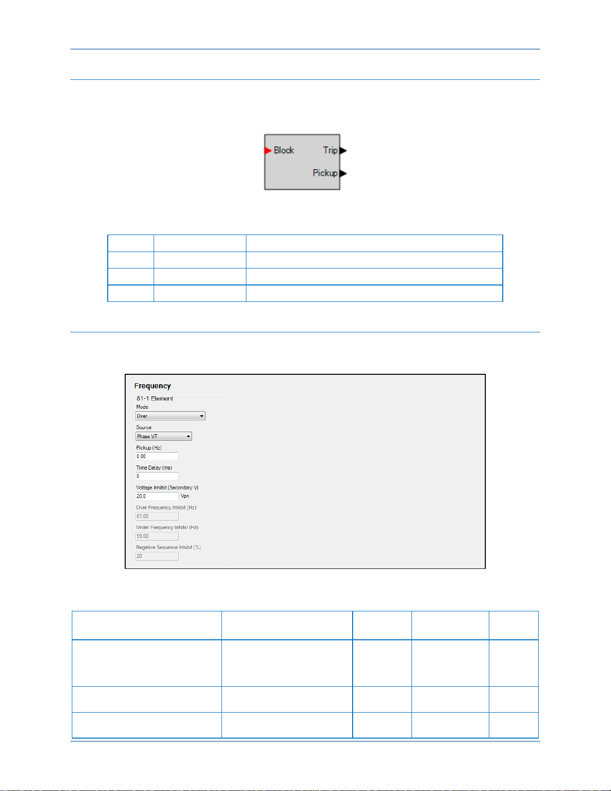
64 9424200995 Rev H
Name
Logic Function
Purpose
Block
Input
Disables the 81 function when true
Trip
Output
True when the 81 element is in a trip condition
Pickup
Output
True when the 81 element is in a pickup condition
Unit of
Measure
Disabled, Over, Under,
or Negative Rate of Change
Phase
VT
0 or 0.2 to 20 for ROC mode
0 or 15 to 70 for O/U mode
hertz/sec (ROC)
hertz (O/U)
Logic Connections
Frequency element logic connections are made on the BESTlogicPlus screen in BESTCOMSPlus. The
frequency element logic block is illustrated in Figure 46. Logic inputs and outputs are summarized in
Table 20.
Figure 46. Frequency Element Logic Block
Table 20. Logic Inputs and Outputs
Operational Setti ngs
Frequency element operational settings are configured on the Frequency settings screen (Figure 47) in
BESTCOMSPlus. Setting ranges and defaults are summarized in Table 21.
Figure 47. Frequency Settings Screen
Table 21. Operational Settings
Setting Range Increment
Default
Mode
Source Phase VT or Aux VT n/a n/a
Pickup
Frequency (81) Protection BE1-11t
Rate of Change,
Positive Rate of Change,
n/a n/a Disabled
0.01
0
Page 77

9424200995 Rev H 65
Unit of
Measure
Time Delay
0 to 600,000
varies
milliseconds
0
Voltage Inhibit
0 or 15 to 250
0.1
volts*
20
Over Frequency Inhibit
15 to 70 Hz
0.01
hertz
61
Under Frequency Inhibit
15 to 70 Hz
0.01
hertz
59
Negative Sequence
Inhibit
Setting Range Increment
81ROC
0 to 99 1 percent 20
* Phase-to-phase and phase-to-neutral settings depend on the Phase VT and Aux VT connection
settings. Refer to the Configuration chapter for more information on these settings.
Default
BE1-11t Frequency (81) Protection
Page 78

66 9424200995 Rev H
Frequency (81) Protection BE1-11t
Page 79

9424200995 Rev H 67
Negative-Sequence Overcurrent (46) Protection
Negative-sequence overcurrent protection is included as a mode of the 50 (Instantaneous Overcurrent)
and the 51 (Inverse Overcurrent) elements. Refer to the chapters on Instantaneous Overcurrent (50)
Protection and Inverse Overcurrent (51) Protection for information on how to set up and program the I2
(negative-sequence overcurrent) mode of the 50 and the 51 elements.
For years, protection engineers have enjoyed increased sensitivity to phase-to-ground unbalances with
the application of ground relays. Ground relays can be set more sensitively than phase relays because a
balanced load has no ground (3I0) current component. When using negative-sequence mode, the 50 and
51 elements can provide similar increased sensitivity to phase-to-phase faults because a balanced load
has no negative-sequenc e ( I2) current component.
Pickup Settings
A typical setting when using negative-sequence mode for the 50 or 51 elements might be one-half the
phase pickup setting in order to achieve equal sensitivity to phase-to-phase faults as three-phase faults.
This number comes from the fact that the magnitude of the current for a phase-to-phase fault is
(87%) of the three-phase fault at the same location. This is illustrated in
Figure 48.
/2
3
√
The phase-to-phase fault is made up of both positive and negative-sequence components as shown in
Figure 49
the magnitude of the total phase current. When these two factors (
factors cancel which leaves the one-half factor.
or a phase-to-phase fault, the magnitude of the negative-sequence component is 1/√3 (58%) of
3
/2 and 1/√3) are combined, the √3
√
BE1-11t Negative-Sequence Overcurrent (46) Protection
Figure 48. Phase-to-Phase Fault Magnitude
Page 80

68 9424200995 Rev H
Fault Type
Multiplier
Ph-Ph
m = 1.732
Ph-Ph-G
m > 1.732
Ph-G
m = 3
three-phase
m = infinity
Figure 49. Sequence Components for an A-B Fault
Coordination Settings
The 51-x negative-sequence settings should be checked for coordination with phase-only sensing devices
such as downstream fuses and reclosers and/or ground relays. To plot the negative-sequence time
current characteristics on the same plot for the phase devices, you need to multiply the negativesequence element pickup value by the correct multiplier. The multiplier is the ratio of phase current to
negative-sequence current for the fault type for which you are interested. To plot the negative-sequence
time current characteristics on the same plot for the ground devices, you need to multiply the pickup value
by the multiplier for phase-to-ground faults (see Table 22).
Table 22. Fault Type Multipliers
For example, a downstream phase 51-x element has a pickup of 150 amperes. The upstream 51-x
negative-sequence element has a pickup of 200 amperes. To check the coordination between these two
elements for a phase-to-phase fault, the phase overcurrent element would be plotted normally with pickup
at 150 amperes. The 51-x negative-sequence element would be shifted to the right by the appropriate
factor m. Thus, the characteristic would be plotted on the coordination graph with pickup at: (200
amperes) ∗ 1.732 = 346 amperes.
Generally, for coordination with downstream phase overcurrent devices, phase-to-phase faults are the
most critical to consider. All other fault types result in an equal or greater shift of the time current
characteristic curve to the right on the plot.
Negative-Sequence Overcurrent (46) Protection BE1-11t
Page 81

9424200995 Rev H 69
Instantaneous Overcurrent (50) Protection
Nine instantaneous overcurrent (50) elements monitor the current applied to the BE1-11t. An element can
be configured to protect against overcurrent by monitoring a single- or three-phase system, neutral
current, positive-sequence current, negative-sequence current, ground current, or unbalanced current.
The nine, identical instantaneous overcurrent protection elements are designated 50-1, 50-2, 50-3, 50-4,
50-5, 50-6, 50-7, 50-8, and 50-9. Element logic connections are made on the BESTlogic™Plus screen in
BESTCOMSPlus® and element operationa l settings a re confi gur ed on the Instan t aneo us Over cur r ent
settings screen in BESTCOMSPlus. A summary of the logic inputs and outputs and operational settings
appears at the end of this chapter.
BESTCOMSPlus Navigation Path: Settings Explorer, Protection, Current, Instantaneous Overcurrent
(50)
HMI Navigation Path: Settings Explorer, Protection, Settings Group x (where x = 0 to 3), Current
Protection, Instant Overcurrent 50
Element Operation
Instantaneous overcurrent protection can be used to protect equipment from damage caused by phase
failure, forward/reverse phase sequence, or phase unbalance.
Modes of Protection
Nine modes of protection are available: IA, IB, IC, Three-Phase, 3I0, I1, I2, IG, and Unbalance.
IA, IB, or IC Mode
The instantaneous overcurrent protection elements include three independent comparators, one for each
phase. Mode selection determines which phase pickup is required to activate protection.
Three-Phase Mode
The instantaneous overcurrent protection elements include three independent comparators, one for each
phase. Protection is activated when any of the three phases increases above the Pickup setting.
3I0 Mode
3I0 mode provides neutral overcurrent protection in a three-phase system.
I1 Mode
I1 mode provides positive-sequence overcurrent protection in a three-phase system.
I2 Mode
I2 mode provides negative-sequence overcurrent protection in a three-phase system. Refer to the
Negative-Sequence Overcurrent (46) Protection chapter for more information.
IG Mode
IG mode provides ground fault protection in a three-phase system.
Unbalance Mode
Unbalance mode provides unbalanced current protection. Two methods are available to calculate
unbalanced current. The first method is based on the negative-sequence current divided by the positivesequence current while the second method is based on the average current. The calculation method must
BE1-11t Instantaneous Overcurrent (50) Protection
Page 82

70 9424200995 Rev H
be specified on the System Parameters, Sensing Transformers screen in BESTCOMSPlus. Refer to the
Configuration chapter for more information.
CT Source
The CT Source setting configures an instantaneous overcurrent element to monitor CT circuit 1 or CT
circuit 2. CT circuit 1 terminals are designated D1 (IA1) through D8 (IG1) and CT circuit 2 terminals are
designated F1 (IA2) through F8 (IG2). For an illustration, refer to the Terminals and Connectors chapter.
Direction
An instantaneous overcurrent element can be configured for forward or reverse tripping. Refer to the
Directional Overcurrent (67) Protection chapter for more information.
Pickup and Trip
The Pickup output occurs first, followed by the Trip output.
Pickup
The Pickup output becomes true when the measured current increases above the current threshold
established by the Pickup setting. In BESTlogicPlus, the Pickup output can be connected to other logic
elements to annunciate the condition, con tr ol other elements in logic, and start the fault recorder (logic
element FAULTTRIG).
Assertion of the Pickup output initiates a timer that begins timing to a trip. The duration of the timer is
established by the Time Delay setting. A Time Delay of zero (0) makes the 50 element instantaneous with
no intentional time delay.
If the pickup condition subsides before the element delay expires, the timer and Pickup output are reset,
no corrective action is taken, and the element is rearmed for any other occurrences of overcurrent.
Trip
The Trip output becomes true if an overcurrent condition persists for the duration of the element Time
Delay setting. In BESTlogicPlus, the Trip output can be connected to other logic elements and to a
physical relay output to annunciate the condition and to initiate corrective action. If a target is enabled for
the element, the BE1-11t will record a target when the Trip output becomes true. See the Fault Reporting
chapter for more information about target reporting.
Element Blocking
The Block input provides logic-supervision control of the element. When true, the Block input disables the
element by forcing the Trip and Pickup outputs to logic 0 and resetting the element timer. Connect the
element Block input to the desired logic in BESTlogicPlus. When the element is initially selected from the
Elements view, the default condition of the Block input is a logic 0.
Logic Connections
Instantaneous overcurrent element logic connections are made on the BESTlogicPlus screen in
BESTCOMSPlus. The instantaneous overcurrent element logic block is illustrated in Figure 50. Logic
inputs and outputs are summarized in Table 23.
Instantaneous Overcurrent (50) Protection BE1-11t
Figure 50. Instantaneous Overcurrent Element Logic Block
Page 83
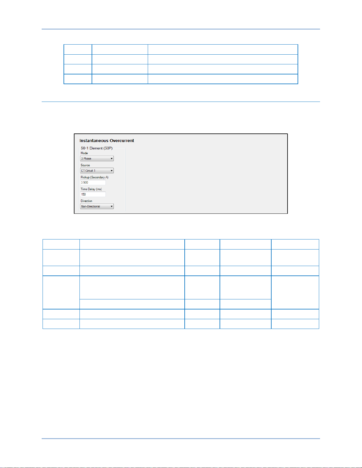
9424200995 Rev H 71
Name
Logic Function
Purpose
Block
Input
Disables the 50 function when true
Trip
Output
True when the 50 element is in trip condition
Pickup
Output
True when the 50 element is in pickup condition
Setting
Range
Increment
Unit of Measure
Default
Disabled, IA, IB, IC, 3 Phase,
3I0, I1, I2, IG, or Unbalance
Source
CT Circuit 1 or CT Circuit 2
n/a
n/a
CT Circuit 1
0 or 0.5 to 150 (5A CTs)
0 or 0.01 to 7.5 (SEF)
2 to 100 (Unbalance mode)
1
percent
Time Delay
0 to 60,000
varies
milliseconds
0
Direction
Forward, Reverse, or Non-Directional
n/a
n/a
Non-Directional
Table 23. Logic Inputs and Outputs
Operational Setti ngs
Instantaneous overcurrent element operational settings are configured on the Instantaneous Overcurrent
(50) settings screen (Figure 51) in BESTCOMSPlus. Setting ranges and defaults are summarized in
Table 24.
Figure 51. Instantaneous Overcurrent Settings Screen
Mode
Pickup
0 or 0.1 to 30 (1A CTs)
Table 24. Operational Settings
n/a n/a Disabled
varies amps
0
BE1-11t Instantaneous Overcurrent (50) Protection
Page 84

72 9424200995 Rev H
Instantaneous Overcurrent (50) Protection BE1-11t
Page 85

9424200995 Rev H 73
Breaker Failure (50BF) Protect ion
The breaker failure (50BF) element provides protection and security for the power system against failure
of the monitored breaker.
Element logic connect ions are made on the BE ST logic™Plus screen in BESTCOMSPlus® and eleme nt
operational settings are configured on the Breaker Fail (50BF) settings screen in BESTCOMSPlus. A
summary of the logic inputs and outputs and operational settings appears at the end of this chapter.
BESTCOMSPlus Navigation Path: Settings Explorer, Protection, Current, Breaker Fail (50BF)
HMI Navigation Path: Settings Explorer, Protection, Settings Group x (where x = 0 to 3), Current
Protection, Breaker Fail 50BF
Element Operation
The 50BF element monitors the current to determine whether or not current continues to flow into a
faulted circuit after a circuit breaker has been directed to interrupt the circuit. In the event that current
continues to flow into the faulted circuit (after a defined period of time has elapsed sufficient for the
breaker to have interrupted the current), then the circuit breaker is considered to have failed, and steps
must be initiated to trip the next set of breakers upstream in the power system. Breaker failure protection
may be applied to any portion of the power system where failure of a circuit breaker to operate properly
could result in severe system damage or instability.
Contact Sensing
Before any relay output can occur, there must first be an initiating signal from external contacts. Two
possible initiating signals are either the 52 Breaker Fail Initiate (52BFI) signal or the 50 Breaker Fail
Initiate (50BFI) signal. Contact sensing circuitry allows the BE1-11t to monitor external contacts for the
presence of these signals.
Logic to start the breaker failure timer via the 52BFI input is provided with breaker status supervision.
Both the breaker status and the 52 BFI logic input must be true for the 52BFI logic input to cause a trip
condition. Information on setting up the breaker status logic can be found in the Breaker Monitoring
chapter.
Control Timer
The control timer provides a window of opportunity for a breaker failure output. It improves dependability
by sealing in the initiate request to prevent stopping of a breaker failure timing if the tripping relay drops
out prematurely. The control timer is initiated by a 50BFI signal. Upon sensing the 50BFI transition from a
0 to 1 state, the control timer seals in the 50BFI signal for the duration of the Control Timer setting. If the
control timer expires and the 50BFI signal is still present, an alarm signal occurs. A control timer setting of
zero (0) disables the control timer seal-in function allowing the control timer to follow the 50BFI input.
ReTrip and Trip
Phase and neutral fault detectors monitor current in the phases and the ground current input. At least one
of these fault detectors must be picked up to start the breaker failure delay timer.
The adjustable delay timer allows current to decay after the breaker is tripped. The delay timer is initiated
when either the 52BFI input or the 50BFI input becomes true. When both signals are false, the breaker
delay timer is stopped.
ReTrip
The ReTrip output is true when the delay timer is actively timing. The delay timer can be stopped by either
the fast current detector or the Block logic input being asserted. In BESTlogicPlus, the ReTrip output can
be connected to other logic elements to annunciate the condition, control other elements in logic, and
start the fault recorder (logic element FAULTTRIG).
BE1-11t Breaker Failure (50BF) Protection
Page 86

74 9424200995 Rev H
Trip
The Trip output becomes true if sensed current exceeds the Phase or Ground Pickup setting and the
delay time expires in the window of opportunity (before the control timer expires). In BESTlogicPlus, the
Trip output can be connected to other logic elements and to a physical relay output to annunciate the
condition and to initiate corrective action. If a target is enabled for the element, the BE1-11t will record a
target when the Trip output becomes true. See the Fault Reporting chapter for more information about
target reporting.
Fast Current Detector
The fast current detector directly determines when the current in the poles of the breaker has been
interrupted without having to wait for the fault current samples to clear the one-cycle filter time used by
the normal current measurement function. This function has less than one cycle dropout time.
The fast current detector logic is true if the current has been interrupted and is used to stop the breaker
failure timer. The I=0 algorithm looks at the sample data directly and does not rely upon the 1 cycle
phasor estimation calculation. It rejects dc tail-off by looking for the characteris tic ex pone nti al decay.
Current is deemed to be interrupted when the current in all three phases is below 5% nominal or if the
current is decaying exponentially. Only the three phase currents are monitored by this function.
CT Source
The CT Source setting configures the breaker failure element to monitor CT circuit 1 or CT circuit 2. CT
circuit 1 terminals are designated D1 (IA1) through D8 (IG1) and CT circuit 2 terminals are designated F1
(IA2) through F8 (IG2). For an illustration, refer to the Terminals and Connectors chapter.
Programmable Alarm
A Breaker Failure alarm is provided to indicate an alarm condition when the 50BF element trips. The
alarm appears on the front-panel display, web page interface, and on the Alarms metering screen in
BESTCOMSPlus. Refer to the Alarms chapter for information on how to program alarms.
Element Blocking
The Block input provides logic-supervision control of the element. Element blocking is a useful feature to
prevent inadvertent backup tripping during testing.
When true, the Block input disables the element by forcing the Trip and ReTrip outputs to logic 0 and
resetting the element timers. Connect the element Block input to the desired logic in BESTlogicPlus.
When the element is initially selected from the Elements view, the default condition of the Block input is a
logic 0.
Logic Connections
Breaker failure element logic connections are made on the BESTlogicPlus sc r een in BESTCOMSPlus.
The breaker failure element logic block is illustrated in Figure 52. Logic inputs and outputs are
summarized in Table 25.
Breaker Failure (50BF) Protection BE1-11t
Figure 52. Breaker Failure Element Logic Block
Page 87

9424200995 Rev H 75
Name
Logic Function
Purpose
Block
Input
Disables the 50BF function when true
50BFI
Input
Starts the 50BF timer when true
52BFI
Input
Starts the 50BF timer when true
Trip
Output
True after the 50BF Delay Timer expires
ReTrip
Output
True when the 50BF Delay Timer is actively timing
Setting
Range
Increment
Unit of Measure
Default
Mode
Disabled or Enabled
n/a
n/a
Disabled
Source
CT Circuit1 or CT Circuit 2
n/a
n/a
CT Circuit 1
0 or 0.25 to 10.00 (5A CTs)
0 or 0.01 to 0.5 (SEF)
Control Timer
0 or 50 to 999
varies
milliseconds
50
Delay Timer
0 or 50 to 999
varies
milliseconds
50
Table 25. Logic Inputs and Outputs
Operational Setti ngs
Breaker failure element operational settings are configured on the Breaker Fail (50BF) settings screen
(Figure 53) in BESTCOMSPlus. Settings ranges and defaults are summarized in Table 26.
Pickup (Phase & Ground)
0 or 0.05 to 2.00 (1A CTs)
Figure 53. Breaker Fail Settings Screen
Table 26. Operational Settings
varies amps 0
BE1-11t Breaker Failure (50BF) Protection
Page 88

76 9424200995 Rev H
Breaker Failure (50BF) Protection BE1-11t
Page 89

9424200995 Rev H 77
Note
Inverse Overcurrent (51) Protecti on
Nine inverse overcurrent (51) elements monitor the current applied to the BE1-11t. An element can be
configured to protect against overcurrent by monitoring a single- or three-phase system, neutral current,
positive-sequence current, negative-sequence current, ground current, or unbalanced current.
The nine, identical inverse overcurrent protection elements are designated 51-1, 51-2, 51-3, 51-4, 51-5,
51-6, 51-7, 51-8, and 51-9. Element logic connections are made on the BESTlogic™Plus screen in
BESTCOMSPlus® and element operational settings are configured on the Inverse Overcurrent settings
screen in BESTCOMSPlus. A summary of the logic inputs and outputs and operational settings appears
at the end of this chapter.
BE1-11t protection systems enabled for IEC-61850 communication
(style Txxxx5xxxxxxxx) have their inverse overcurrent protection
elements fixed at nine inverse overcurrent elements without voltage
control.
BESTCOMSPlus Navigation Path: Settings Explorer, Protection, Current, Inverse Overcurrent (51)
HMI Navigation Path: Settings Explorer, Protection, Settings Group x (where x = 0 to 3), Current
Protection, Inverse Overcurrent 51
Element Operation
Inverse overcurrent protection can be used to protect equipment from damage caused by phase failure,
forward/reverse phase sequence, or phase unbalance.
Modes of Protection
Nine modes of protection are available: IA, IB, IC, Three-Phase, 3I0, I1, I2, IG, and Unbalance.
IA, IB, or IC Mode
The inverse overcurrent protection elements include three independent comparators and timers, one for
each phase. Mode selection determines which phase pickup is required to activate protection.
Three-Phase Mode
Three-phase mode provides overcurrent protection in a three-phase system when all three phases
increase above the Pickup setting.
3I0 Mode
3I0 mode provides neutral overcurrent protection in a three-phase system.
I1 Mode
I1 mode provides positive-sequence overcurrent protection in a three-phase system.
I2 Mode
I2 mode provides negative-sequence overcurrent protection in a three-phase system. Refer to the
Negative-Sequence Overcurrent (46) Protection chapter for more information.
IG Mode
IG mode provides ground fault protection in a three-phase system.
BE1-11t Inverse Overcurrent (51) Protection
Page 90

78 9424200995 Rev H
=
+ +
=
|
1
|
Parameter
Description
Explanation
T
Time to trip
Time that the 51-x function will take to time out and trip.
D
Time dial setting
Time dial setting for the 51-x function.
Measured current in multiples of pickup. The timing algorithm
has a dynamic range of 0 to 40 times pickup.
Coefficient specific to
selected curve
Coefficient specific to
selected curve
Affects a constant term in the timing equation. Has greatest
effect on curve shape at high multiples of tap.
Unbalance Mode
Unbalance mode provides unbalanced current protection. Two methods are available to calculate
unbalanced current. The first method is bas ed on the negative-sequence current divided by the posit ivesequence current while the second method is based on the average current. The calculation method must
be specified on the System Parameters, Sensing Transformers screen in BESTCOMSPlus. Refer to the
Configuration chapter for more information.
CT Source
The CT Source setting configures an inverse overcurrent element to monitor CT circuit 1 or CT circuit 2.
CT circuit 1 terminals are designated D1 (IA1) through D8 (IG1) and CT circuit 2 terminals are designated
F1 (IA2) through F8 (IG2). For an illustration, refer to the Terminals and Connectors chapter.
Direction
An inverse overcurrent element can be configured for forward or reverse tripping. Refer to the Directional
Overcurrent (67) Protection chapter for more information.
Timings
Each inverse overcurrent element has a Curve setting. The following paragraphs describe the available
timing curves. The user can select integrating reset timing to make the protective element use integrated
reset and emulate an electromechanical induction disk reset characteristic.
Standard Curves
There are 22 standard curves available including standard inverse, short inverse, moderately inverse,
long inverse, very inverse, and extremely inverse. Refer to the Time Curve Characteristics chapter for
specific information on each cur ve.
Programmable Curves
An available programmable curve can be used to create a custom curve by selecting coefficients in the
inverse time characteristic equation. When inverse time overcurrent characteristic curve P is selected, the
coefficients used in the equation are those defined by the user. Inverse overcurrent characteristics for trip
and reset programmable curves are defined by Equation 6 and Equation 7. These equations comply with
IEEE Std C37.112-1996 - IEEE Standard Inverse-Time Characteristic Equations for Overcurrent Relays.
Definitions for these equations are provided in Table 27. The curve-specific coefficients are defined for
the standard curves as listed in the Time Curve Characteristics chapter.
Equation 6. Time OC Characteristics for Trip
Table 27. Definitions for Equation 6 and Equation 7
Equation 7. Time OC Characteristics for Reset
M Multiple of pickup
A
B
Inverse Overcurrent (51) Protection BE1-11t
Affects the effective range of the time dial.
Page 91
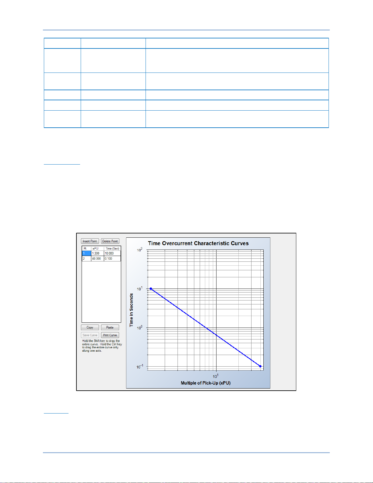
9424200995 Rev H 79
Parameter
Description
Explanation
Affects the multiple of PU where the curve would approach
curve shape near pickup.
Exponent specific to
selected curve
Affects how inverse the characteristics are. Has greatest effect
on curve shape at low to medium multiples of tap.
K
Constant
Characteristic minimum delay term.
T
Time to reset
Relevant if 51-x function is set for integrating reset.
Coefficient specific to
selected curve
C
Coefficient specific to
selected curve
infinity if allowed to continue below pickup. Has greatest effect on
N
R
Affects the speed of reset when integrating reset is selected.
Curve coefficients are entered on the Inverse Overcurrent (51) settings screen in BESTCOMSPlus.
Programmable curve coefficients can be entered only when the P curve is chosen for the protection
element from the Curve drop-down menu.
Table Curves
BESTCOMSPlus is used to set the 51 element Table Curves (T1, T2, T3, and T4). Using the Settings
Explorer within BESTCOMSPlus, open the Protection, Current, Table Curve (1, 2, 3, or 4) tree branch and
select the table curve to be modified. Refer to Figure 54. A minimum of 2 and maximum of 40 points can
be entered for any one T curve. When you are satisfied with the values chosen, select Save Curve. Use
the Settings Explorer to browse to the 51-x element you wish to program and use the drop-down menu
under Curve to select T1, T2, T3, or T4.
Table curves can be entered regardless of the curve chosen for the protection element. However, the
table curve will not be enabled until T1, T2, T3, or T4 is selected as the curve for the protective element.
Figure 54. Inverse Overcurrent Table Curve
46 Curve
The 46 curve is a special curve designed to emulate the I2t withstand ratings of generators using what is
frequently referred to as the generator’s K factor. Do not confuse the 46 curve with the I2 mode. The 46
curve was designed for use with the I2 mode. However, in actuality, the 46 curve can be selected for use
with any mode of the inverse overcurrent element as well.
BE1-11t Inverse Overcurrent (51) Protection
Page 92

80 9424200995 Rev H
To use the 46 curve, the user should determine the K factor of the generator and the continuous (I2)2t
rating of the generator (supplied by the manufacturer) and use this to set the time dial and pickup for the
46 curve by the process described in the Time Curve Characteristics chapter. The K factor is the time the
generator can withstand 1 per unit I
where 1 pu is the BE1-11t setting for nominal current.
2
Pickup and Trip
The Pickup output occurs first, followed by the Trip output.
Pickup
The Pickup output becomes true when the measured current increases above the current threshold
established by the Pickup setting. In BESTlogicPlus, the Pickup output can be connected to other logic
elements to annunciate the condition, control other elements in logic, or start the fault recorder (logic
element FAULTTRIG).
Assertion of the Pickup output initiates a timer that begins timing to a trip. The duration of the timer is
established by the Time Dial and Curve settings. A Time Dial setting of zero (0) makes the 51 element
instantaneous with no intention al tim e delay.
If the pickup condition subsides before the calculated inverse time expires, the timer and Pickup outputs
are reset, no corrective action is taken, and the element is rearmed for any other occurrences of
overcurrent.
Trip
The Trip output becomes true if an overcurrent pickup condition persists for the duration of the calculated
inverse time. In BESTlogicPlus, the Trip output can be connected to other logic elements and to a
physical relay output to annunciate the condition and initiate corrective action. If a target is enabled for the
element, the BE1-11t will record a target when the Trip output becomes true. See the Fault Reporting
chapter for more information about target reporting.
Voltage Restraint Mode (51/27R)
When a 51 element is set for 3 Phase, IA, IB, or IC mode, the 51 element can be set for voltage control or
voltage restraint mode of operation. This feature is used to allow increased phase overcurrent sensitivity
while providing security from operation due to load current. This feature is also often used for generator
backup protection to ensure delayed tripping during a short-circuit where the fault current contribution
from the generator falls to a value close to the full-load rating of the generator.
A Voltage Restraint threshold of zero (0) disables voltage restraint/control and allows the 51 element to
operate normally.
Control Mode
When set for Control mode of operation, the 51 element is disabled until the measured voltage drops
below the Voltage Restraint threshold. Thus, as long as the voltage on the appropriate phase is above the
Voltage Restraint threshold, the 51 element will be blocked. When set for this mode of operation, the 51
Pickup setting is typically set near or below load current levels.
Restraint Mode
When set for Restraint mode of operation, the pickup of the 51 element is adjusted based upon the
magnitude of the measured voltage. Figure 55 shows how the 51 Pickup setting is adj ust ed in response
to the measured voltage level. Equation 8 determines the pickup level for the 51 element when the
measured voltage is between 25% and 100% of the Voltage Restraint threshold. Below 25%, the pickup
level stays at 25%. Above 100%, the pickup level stays at 100%. For example, if the Voltage Restraint
threshold is set for 120 V and the measured voltage on the appropriate phase is 100 V (83% of the
Voltage Restraint threshold), the phase overcurrent pickup level will be reduced to 83% of its setting.
When set for this mode of operation, the 51 element Pickup setting is typically set above worst case, load
current levels.
Inverse Overcurrent (51) Protection BE1-11t
Page 93

9424200995 Rev H 81
Phase VT Connection
51/27 Mode
51A
51B
51C
4W
Vpp
Vab
Vbc
Vca
4W
Vpn
Van
Vbn
Vcn
3W
Vpp
Vab
Vbc
Vca
AN
Vpn
Van
n/a
n/a
BN
Vpn
n/a
Vbn
n/a
CN
Vpn
n/a
n/a
Vcn
AB
Vpp
Vab
n/a
n/a
BC
Vpp
n/a
Vbc
n/a
CA
Vpp
n/a
n/a
Vca
=
Equation 8. Restraint Pickup Level
Figure 55. 51 Phase Pickup Level Compensation
× 51
Phase VT Configuration
The 51/27R function can be set to monitor either Vpp or Vpn depending upon the Phase VT Connection
settings. See the Configuration chapter for details on how to set the phase VT connections. Table 28
shows which voltage measurements are used by each 51 element for each possible phase VT connection
and 51/27 voltage monitoring mode setting.
Table 28. Phase VT Connection Cross Reference
BE1-11t Inverse Overcurrent (51) Protection
Page 94

82 9424200995 Rev H
Note
Name
Logic Function
Purpose
Block
Input
Disables the 51 function when true
Trip
Output
True when the 51 element is in trip condition
Pickup
Output
True when the 51 element is in pickup condition
For single-phase sensing, the unmonitored phase is not restrained or
controlled. These phases are marked in the table by n/a (not
applicable).
When single-phase voltage sensing is used, only the inverse overcurrent element on the phase with
voltage magnitude information is affected by the 51/27R feature. Thus, in voltage control mode, the 51
elements on the two unmonitored phases will always be disabled. In voltage restraint mode, the 51
elements on the two unmonitored phases will not have their overcurrent pickup settings adjusted from
100%.
Element Blocking
Fuse Loss
The fuse loss element (60FL) can also be set to supervise the 51/27R function. It is possible to set the
60FL element to automatically prevent misoperation on loss of sensing voltage. When the 51/27R
function is set for control and a 60FL condition is detected, the inverse overcurrent elements will be
disabled. When the 51/27R function is set for restraint and a 60FL condition is detected, the inverse
overcurrent elements will remain enabled but the picku p will not be adjus ted fr om 100% of its setti ng. Se e
the Fuse Loss (60FL) chapter for more information.
Protective elements blocked by 60FL should be set so that trip times are 60 milliseconds or greater to
assure proper coordination of blocking.
Block Logic Input
The Block input provides logic-supervision control of the element. When true, the Block input disables the
element by forcing the Trip and Pickup outputs to logic 0 and resetting the element timer. Connect the
element Block input to the desired logic in BEST logicPlus. When the element is initially selected from the
Elements view, the default condition of the Block input is a logic 0.
Logic Connections
Inverse overcurrent element logic connections are made on the BESTlogicPlus screen in
BESTCOMSPlus. The inverse overcurrent element logic block is illustrated in Figure 56. Logic inputs and
outputs are summarized in Table 29.
Figure 56. Inverse Overcurrent Element Logic Block
Table 29. Logic Inputs and Outputs
Operational Setti ngs
Inverse overcurrent element operational settings are configured on the Inverse Overcurrent (51) settings
screen (Figure 57) in BESTCOMSPlus. Setting ranges and defaults are sum marized in Table 30.
Inverse Overcurrent (51) Protection BE1-11t
Page 95

9424200995 Rev H 83
Unit of
Measure
Disabled, IA, IB, IC, 3 Phase,
3I0, I1, I2, IG, or Unbalance
Source
CT Circuit 1 or CT Circuit 2
n/a
n/a
CT Circuit 1
0 or 0.5 to 16 (5A CTs)
0 or 0.01 to 0.8 (SEF)
2 to 100 (Unbalance mode)
1
percent
0 to 9.9
0.0 to 99 (46 only)
See the Time Curve
Characteristics chapter.
Forward, Reverse, or Non-
Directional
Non-
Directional
Reset Timing
Integrating or Instantaneous
n/a
n/a
Instantaneous
A Coefficient
0 to 600
0.00001
A Coefficient
0.26630
B Coefficient
0 to 25
0.00001
B Coefficient
0.03393
Figure 57. Inverse Overcurrent Settings Screen
Table 30. Operational Settings
Setting Range Increment
Mode
0 or 0.1 to 3.2 (1A CTs)
n/a n/a Disabled
varies amps
Pickup
Time Dial
Curve
Direction
0 to 1 (IEC curves only)
varies units 0
n/a n/a S1
n/a n/a
Default
0
BE1-11t Inverse Overcurrent (51) Protection
Page 96

84 9424200995 Rev H
Unit of
Measure
C Coefficient
0 to 1
0.00001
C Coefficient
1.00000
N Coefficient
0.5 to 2.5
0.00001
N Coefficient
1.29690
K Coefficient
n/a
n/a
K Coefficient
0.02800
R Coefficient
0 to 30
0.00001
R Coefficient
0.50000
Voltage Restraint
Mode
Voltage Restraint
Setpoint
Setting Range Increment
Disabled, Control, or Restraint n/a n/a Disabled
0 or 30 to 250 varies volts 0
Default
Inverse Overcurrent (51) Protection BE1-11t
Page 97

9424200995 Rev H 85
Directional Overcurrent (67) Protect i on
The 67 element provides directional supervision for the overcurrent tripping elements. Two reference
quantities for each polarizing method are compared to establish directional signals for controlling
operation of the phase, ground, and negative-sequence overcurrent elements. Directionality is derived
from a comparison between internally calculated sequence voltages V1, V2, V0 (magnitude and angle)
and calculated values of I1, I2, 3I0, I0, (magnitude and angle) and measured IG (magnitude and angle).
Regardless of fault direction, the angle of the sequence voltages and the ground current source will
always be the same while the angle of the currents (I1, I2, 3I0/IN, I0, IG operate) will change based on
the direction of fault current flow.
The directional element can monitor CT circuit 1 or CT circuit 2. The CT source is selected on the
Sensing Transformers settings screen in BESTCOMSPlus®.
Polarization Methods
The polarization methods are as follows:
● Positive-Sequence Polarization – Forward direction is detected is when the apparent Z
of V
) is equal to the positive-sequence maximum torque angle (MTA), ±90°.
1/I1
● Negative-Sequ enc e Polar ization – Forward direction is detected is when the apparent Z
of
-V2/I2) is equal to the negative-sequence maximum torque angle (MTA), ±90°. (See Note 1.)
● Zero-Sequence Voltage Polarization – Forward direction is detected is when the apparent Z
(angle of V
) is equal to the zero-sequence maximum torque angle (MTA), ±90°. (See Note 1.)
0/I0
However, the BE1-11t has two forms of zero-sequence voltage available to it (calculated V
phase voltages or V
(calculated I
from the phase currents or IG from the protection system's IG1 or IG2 input). This results
0
from a broken delta VT) and two forms of zero-sequence current available to it
X
angle (angle
1
angle (angle
2
angle
0
from the
0
in four options for zero-sequence voltage polarization:
○ Calculated V
○ Calculated V
○ V
verses calculated I0
x
○ V
verses IG
x
○ All four forms of zero-sequence voltage polarizations use the same MTA value.
● Zero-Sequence Current Polarization – Forward direction is detected is when the phase angle of
current in the ground CT input (IG) is in phase with the calculated I
verses calculated I0
0
verses IG
0
, ±90°.
0
Each of the four internal polarization methods has designated internal bits that are used in the BE1-11t for
direction identification, one for forward direction and one for reverse direction. Combined, these eight bits
are referred to as the directional status byte and are used to control the various overcurrent elements.
Note 1: The negative and zero-sequence angle of maximum torque has a built in 180-degree phase shift
that arises out of the calculation methods described at the end of this chapter.
Positive-Seque nc e Polar iza tion is used to determine direction for three-phase faults. Under these
conditions, very little negative or zero-sequence quantities are present, making the other polarization
methods unreliable for this fault condition. For close-in faults, the BE1-11t will also need to depend on
memory voltage to determine direction (see below). Positive-sequence bits are used to supervise the
elements in single or 3 phase mode.
To provide memory, the positive-sequence voltage is stored continuously until a fault occurs. Memory
voltage is used when the positive-sequence voltage falls below the minimum acceptable level of 12 volts.
The BE1-11t maintains memory voltage for 20 cycles to allow tripping for close in faults. When using
memory voltage polarization, the BE1-11t assumes nominal system frequency.
BE1-11t Directional Overcurrent (67) Protection
Page 98

86 9424200995 Rev H
Negative-Sequence Polar iz atio n is used to test directionally for all fault types except three-phase faults.
Negative-sequence bits are used to supervise phase, neutral, and negative-sequence overcurrent modes.
With load flow and low fault currents, it is possible for the positive-sequence bits to be set at the same
time negative-sequence bits are true. Under these conditions, the negative-sequence bits have priority
and the positive-sequence bits are cleared.
Zero-Sequence Voltage Polarizat ion is used to test directionally for ground faults and is used to supervise
only in neutral overcurrent mode (V0IN, V0IG, VXIN, CXIN, VXIG, or CXIG). The neutral overcurrent
elements can be set to operate on either calculated I
or independent ground input IG. The four types of
0
zero-sequence polarization methods were described above. Typical ac connections for external sources
(a broken delta VT) are provided in the Ty p ical C onnec t ions chapter.
of V
0
Zero-Sequence Current Polarization is also used to test directionally for ground faults and is used to
supervise the neutral overcurrent elements.
Polarization summary for tripping elements is as follows:
• Phase mode: Positive-Sequence; Negative-Sequence
• Negative-Sequence mode: Negative-Sequence
• Neutral mode: Negative-Sequence; Zero-Sequence Volt; Zero-Sequence Current
The neutral overcurrent elements can be supervised by various polarization methods using either or both
zero-sequence and negative-sequence quantities. This is necessary depending on the application and
fault conditions applied to the BE1-11t. For example, negative-sequence polarizing can be used when
zero-sequence mutual coupling effects cause zero-sequence polarizing elements to lose directionality. In
addition, high Z ground faults might cause values of zero-sequence voltage too low to measure during a
fault, making zero-sequence polarization unreliable. A similar condition can occur with the negativesequence voltage or current, although it is less likely. Under these conditions, a user might need to use
current polarization or dual polarization to provide reliable directional tripping.
Polarization Settings
Polarization methods are configured on the Polarization (67N) settings screen (Figure 58) in
BESTCOMSPlus. Setting ranges and defaults are summarized in Table 31.
BESTCOMSPlus Navigation Path: Settings Explorer, Protection, Current, Polarization (67N)
HMI Navigation Path: Settings Explorer, Protection, Settings Group x (where x = 0 to 3), Current
Protection, Directional Current 67
Figure 58. Polarization (67N) Settings Screen
Directional Overcurrent (67) Protection BE1-11t
Page 99

9424200995 Rev H 87
Setting
Range/Purpose
Default
IG
Use Zero Sequence Current Polarization
Q
Use Negative Sequence Polarization
V
Use Zero Sequence Polarization
IG/Q/V*
Use all three polarization methods
IG/Q*
Use IG and Q polarization methods
IG/V*
Use IG and V polarization methods
Q/V*
Use Q and V polarization methods
VOIN
Calculated Zero Sequence Volt, Calculated Zero Sequence Current
VOIG
Calculated Zero Sequence Volt, Measured Ground Current
VXIN
Measured 3V0-VX, Calculated Zero Sequence Current
VXIG
Measured 3V0-VX, Measured Ground Current
Internal Constant
Purpose
Value
Positive-Sequence
Minimum I1 current threshold for Positive-Sequence test
0.50 A for
for 1A CTs
Zero-Sequence Current
Minimum 3I0 current threshold for Current Polarization test
0.25 A for
for 1A CTs
Table 31. Polarization Settings
67N Polarization
Method
Zero-Sequence
Mode
IG/Q/V
VOIN
* Modes IG/Q/V, IG/Q, IG/V, and Q/V are logical ORs of Modes IG, Q, and V and are used to set up dual
or possibly triple polarization techniques for the neutral elements. Thus, if more than one directional
supervision element is enabled, any element can enable tripping if the appropriate forward or reverse
directional decision is made.
Maximum Torque Angle and Directional Tests
The directional algorithm requires a user settable maximum torque angle (MTA). There is an MTA setting
for positive-sequence calculations, an MTA setting for negative-sequence calculations, and an MTA
setting for zero-sequence calculations. These settings are separate from the power line impedance
parameters (Z
polarizing MTA different from the "distance to fault" line impedance angle.
Each MTA can be set over the range of 0 to 90 degrees (I lag E) in 1 degree steps. These parameters are
input into the BE1-11t using BESTCOMSPlus. Open the System Parameters, Power System tree branch.
and Z0 used for distance to fault calculations) because some applications require a
1
A fault current is considered to be in a forward direction when the sequence current, after being offset by
the line angle, is in phase with the same sequenc e voltage. The forward direction zone extends for
approximately ±90° from the nominal line angle. A similar argument applies for the reverse direction with
the current 180° out of phase from the voltage. The angle of Z1 is used during positive-sequence
directional test and the angle of Z2 is used during negative-sequence directional test. Likewise, the angle
of Z0 is used during the zero-sequence directional test. Angle compensation is not required for current
polarization since the polarizing quantity IG is inherently compensated.
Note that (not forward) does not necessarily imply reverse. Sufficient current and voltage must be present
to declare direction. Internally, the BE1-11t also uses several constant limits to determine if the system
levels are adequate to perf or m reliab le direc t ion al tests and set directional bits. See Table 32.
Table 32. Internal Constants
Current
5A CTs
and 0.1 A
5A CTs
and 0.05 A
BE1-11t Directional Overcurrent (67) Protection
Page 100

88 9424200995 Rev H
Internal Constant
Purpose
Value
Ground current (IG)
Minimum Ground (IG) current threshold for Current
0.50 A for
for 1A CTs
Negative-Sequence
Voltage
Minimum V2 voltage threshold for Negative-Sequence test
1.2% of
V nominal
Zero-Sequence Voltage
Minimum V0 voltage threshold for Zero-Sequence test
0.75% of
V nominal
External Zero-Sequence
Voltage (VX Input)
Minimum external 3V0 voltage threshold for Zero-Sequence
test
10% of
V nominal
Negative-Sequence Ratio
Minimum ratio between I1 and I2 for Negative-Sequence
test
9%
Zero-Sequence Ratio
Minimum ratio between I1 and 3I0 for Zero-S equ enc e tes t
is 9%
9%
Polarization test
5A CTs
and 0.1 A
If the minimum levels are not met for a particular directional test, then the test is not run and the
directional bits are cleared for that test. For instance, if 3I1 is less than 0.50 A, the positive-sequence test
is skipped and the positive-sequence directional bits are cleared.
The Sequence Ratio refers to the minimum ratio required between the positive-sequence current and
either the negative or the zero-sequence current. A negative-sequence directional test would be allowed if
the negative current were greater than 9% of the positive-sequence current. The same concept applies
for the zero-sequence directional test.
The directional tests are also supervised by the loss of potential function 60FL. If the 60FL bit is true, then
voltage sensing was lost or is unreliable. Under this condition positive, negative, and zero-sequence
directional tests are disabled and their bits are cleared. Current polarization is not affected by the 60FL
since it does not rely on voltage sensing.
The direction bits are updated once per half-cycle. Under sudden current reversal conditions, depending
on the change in magnitude of the forward current to reverse current, the DFT (Discrete Fourier
Transform) could require one cycle to determine polarity of the fault. Beyond this, the 50-x element adds
an additional half-cycle delay when operating in direction mode for security, for an overall response time
of a 50-x element to sudden current reversal of approximately two cycles.
Theory of Using Sequence Impeda nc e s f or Fa ult Direction
When using real world impedances in the Z
approaches zero as one gets closer to the fault and that the same phase's voltage becomes larger the
closer one gets to the source. However, in the sequence domain (zero-, positive-, negative-sequence),
the above concept holds for positive-sequence voltage and current flow, but for negative- and zerosequence current flow, the opposite condition occurs. Negative- and zero-sequence voltage is highest at
the fault location, and lowest at the source. This affects how the BE1-11t uses the angle of maximum
torque to prevent tripping for unusual load flow.
For directional decisions, a BE1-11t is measuring the sequence impedance (Z
the angle that it calculates to the angle of maximum torque with a window of ±90 degrees as forward (or
reverse, depending on the BE1-11t setup). Suppose a radial single source condition exists relative to the
BE1-11t location. The source impedance is Z
Given a source voltage of V
and a fault current of I
Source
Equation 9. Note this equation is true independent of the fault type or the faulted phase.
domain, it is apparent that faulted phase voltage
ABC
/ I
012=V012
and the fault is downstream on a line of impedance Z
Source
the local substation voltage will be shown in
Relay
) and comparing
012
Line
.
Directional Overcurrent (67) Protection BE1-11t
 Loading...