

Page 1

INSTRUCTION MANUA L
FOR
BE1-11
IEC 61850 Protocol
Protection Systems
Publication: 9424200892
Revision: F Sep-14
Page 2

Page 3

9424200892 Rev F i
Caution
Note
Preface
This instruction manual provides detailed information about BE1-11 Protection Systems with the IEC
61850 Protocol. To accomplish this, the following information is provided:
• IEC 61850 engineering
• Logic inputs and outputs configuration
• Operation of BEST61850 software
• File transfer
• Data tags
• Conformance Statements
Conventions Used in this Ma nua l
Important safety and procedural information is emphasized and presented in this manual through
Warning, Caution, and Note boxes. Each type is illustrated and defined as follows.
Warning!
Warning boxes call attention to conditions or actions that may cause
personal injury or death.
Caution boxes call attention to operating conditions that may lead to
equipment or property damage.
Note boxes emphasize important information pertaining to installation
or operation.
BE1-11 Preface
Page 4

ii 9424200892 Rev F
Basler Electric does not assume any responsibility to compliance or noncompliance with national code, local code,
For terms of service relating to this product and software, see the Commercial Terms of Products and Services
document available at www.basler.com/terms.
This publication contains confidential information of Basler Electric Company, an Illinois corporation. It is loaned for
and options are subject to modification without notice. Over time, improvements and revisions may be made to this
manual.
The English-language version of this manual serves as the only approved manual version.
12570 State Route 143
Highland IL 62249-1074 USA
www.basler.com
info@basler.com
Tel: +1 618.654.2341
Fax: +1 618.654.2351
© 2014 by Basler Electric
All rights reserved
First printing: October 2010
Warning!
READ THIS MANUAL. Read this manual before installing, operating, or maintaining the BE1-11. Note
all warnings, cautions, and notes in this manual as well as on the product. Keep this manual with the
product for reference. Only qualified personnel should install, operate, or service this system. Failure to
follow warning and cautionary labels may result in personal injury or property damage. Exercise
caution at all times.
or any other applicable code. This manual serves as reference material that must be well understood prior to
installation, operation, or maintenance.
confidential use, subject to return on request, and with the mutual und er st and ing that it will not be used in any
manner detrimental to the interests of Basler Electric Company and used strictly for the purpose intended.
It is not the intention of this manual to cover all details and variations in equipment, nor does this manual provide
data for every possible contingency regarding installation or operation. The availability and design of all features
publication. Before performing any of the following procedures, contact Basler Electric for the latest revision of this
Preface BE1-11
Page 5

9424200892 Rev F iii
Contents
General Information .................................................................................................................................... 1
IEC 61850 Configuration ........................................................................................................................... 2
IEC 61850 Standard .............................................................................................................................. 2
BESTCOMSPlus® .................................................................................................................................. 2
BEST61850™ ......................................................................................................................................... 3
References ................................................................................................................................................ 3
IEC 61850 Engineering ............................................................................................................................... 5
Engineering Process in IEC 61850 ........................................................................................................... 5
System Configurator .............................................................................................................................. 5
IED Configurator Tool (BEST61850™) ................................................................................................... 6
ICD File (IED Capability Description File) .............................................................................................. 6
SSD File (System Specification Description File) .................................................................................. 6
SCD File (Substation Configuration Description File) ............................................................................ 6
CID File (Configured IED Description File) ............................................................................................ 6
SCL Object Model ..................................................................................................................................... 6
Substation Configuration Description Language (SCL) ............................................................................ 8
Signal Identification .............................................................................................................................. 10
IED Related Naming ............................................................................................................................ 10
Communication Network Section ......................................................................................................... 11
IED Section .......................................................................................................................................... 12
Signal Engineering ............................................................................................................................... 14
BESTCOMSPlus® ...................................................................................................................................... 17
CTLGGIO OPER Output and IN DGGIO OPER Input ............................................................................. 17
CTLGGIO OPER Alarm ........................................................................................................................... 17
IEC61850PTRC Logic Block ................................................................................................................... 17
BEST61850™ ............................................................................................................................................. 19
Installation ............................................................................................................................................... 19
Install BEST61850™ ............................................................................................................................. 19
Menu Bar ................................................................................................................................................. 20
BEST61850™ Settings ............................................................................................................................. 20
Device Info ........................................................................................................................................... 20
Datasets ............................................................................................................................................... 21
Published IED GOOSE ........................................................................................................................ 23
Subscribed IED GOOSE ...................................................................................................................... 24
Report Controls .................................................................................................................................... 25
File Viewer ........................................................................................................................................... 27
Configuration Example ............................................................................................................................ 28
Configure Communication Parameters and Names ............................................................................ 28
Configure DataSets.............................................................................................................................. 29
Configure Published IED GOOSE ....................................................................................................... 31
Configure Subscribed IED G OO SE ..................................................................................................... 32
Configure Report Control Block s ......................................................................................................... 33
Save a CID File as a User Template ................................................................................................... 36
Save a CID File .................................................................................................................................... 37
Upload a CID File to the BE1-11 ......................................................................................................... 38
Measurement Logic Node Configuration ................................................................................................. 38
File Transfer ............................................................................................................................................... 43
Data Tags ................................................................................................................................................... 45
Conformance Statements ......................................................................................................................... 73
MICS ........................................................................................................................................................ 73
PICS ........................................................................................................................................................ 75
PIXIT ........................................................................................................................................................ 80
BE1-11 Contents
Page 6

iv 9424200892 Rev F
TICS......................................................................................................................................................... 86
Mandatory Intop Tissues ..................................................................................................................... 86
Optional IntOp Tissues ........................................................................................................................ 87
Revision History ........................................................................................................................................ 89
Contents BE1-11
Page 7
9424200892 Rev F 1
General Information
This document describes the Basler Electric IEC 61850 Protocol implementation in the BE1-11 series of
protection systems. A BE1-11 is classified as an intelligent electronic device (IED) that is capable of
sending and receiving IEC 61850 messages simultaneously.
The IEC 61850 protocol is an option available when ordering a BE1-11. An Ethernet connection is
required for operation of IEC 61850.
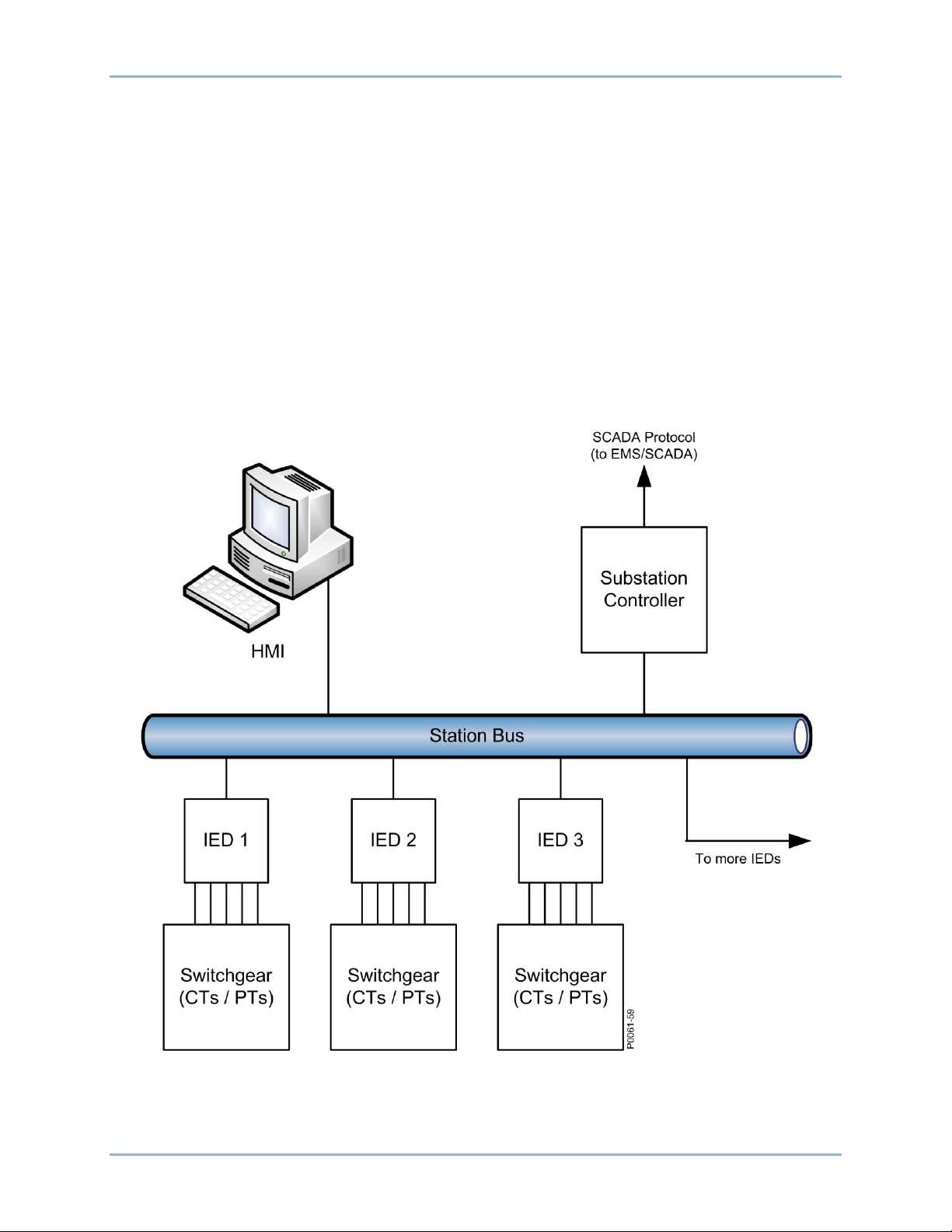
IEC 61850 is a communications infrastructur e that allo ws seamles s integrat ion of IEDs into higher lev el
devices. IEDs from different vendors can be integrated together in this vendor independent infrastructure.
A typical station bus is illustrated in Figure 1.
Protection, control, and metering for the substation are defined in an SCL (Substation Configuration
Language) file. The BE1-11 comes with an SCL compatible ICD (IED Capability Description) file that is
uploaded to the BE1-11 as a CID (configured ICD) file. The substation design developer uses the CID file
to create the portion of the SCD (Substation Configuration Description) file for the overall substation
design.
BE1-11 General Information
Figure 1. Typical Station Bus
Page 8
2 9424200892 Rev F
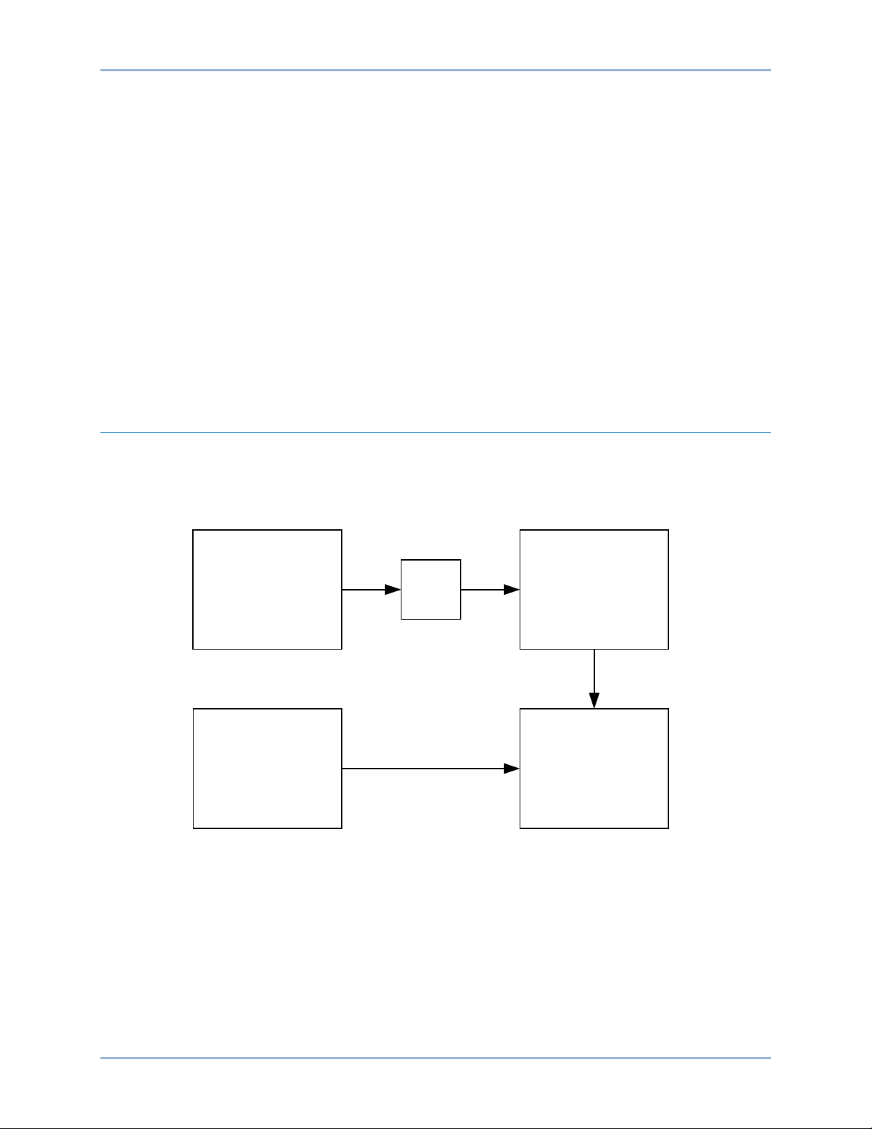
Substation
Configuration Tool
SCD file
Basler
BEST61850
Validate SCL
and Map GOOSE
Basler
BE1-11 System
Basler
BESTCOMSPlus®
Create relay settings BSTX file
P
0
0
6
1-
4
4
Upload settings
Upload SCL
(CID file)
The BE1-11 is capable of transmitting the following items on an IEC 61850 network:
• Configuration Settings
• Metering
• Status
• Alarms
• Targets
• Breaker Operations
• Direct Control
• Fault Records
• Load Profile
• Oscillographic Records
• Sequence of Events Reports
• Unsolicited Reports
• Peer to Peer Control GOOSE
• Device Discovery
IEC 61850 Configurati on
IEC 61850 Standard
The IEC 61850 standard defines the parts for communicating information between IEDs in a substation.
Figure 2 illustrates the Basler IEC 61850 configuration process.
BESTCOMSPlus®
BESTCOMSPlus software is provided with the BE1-11. Refer to the BESTCOMSPlus chapter for more
information.
Figure 2. Basler IEC 61850 Configuration Process
BESTCOMSPlus performs the following tas ks :
• Maps BE1-11 inputs and outputs to IEC 61850 data points that can be read directly with an IEC
• Uses a point-and-click method to configure BE1-11 settings and logic
• Uploads and downloads BE1-11 settings files
• Provides metering and reports from the BE1-11
General Information BE1-11
61850 browser
Page 9

9424200892 Rev F 3
BEST61850™
BEST61850 software is provided with the BE1-11. Refer to the BEST61850 chapter for more information.
BEST61850 performs the following functions:
• Imports an SCD file and extracts the necessary information for each IED in the system
• Maps subscribed GOOSE messages between devices
• Configures published GOOSE messages
• Configures DataSets
• Configures Report Control Blocks (RCB)
• Creates a CID file and uploads it to the IED or exports it to a file
• Performs any additional engineering operations
References
• BE1-11f, Feeder Protection System, Publication 9424200990
• BE1-11g, Generator Protection System, Publication 9424200994
• BE1-11i, Intertie Protectio n System, Publ ic ati on 9424 2 0099 3
• BE1-11m, Motor Protection Sy stem, Public a tio n 9424 2 0099 6
• BE1-11t, Transformer Protection System, Publication 9424200995
• IEC 61850: Communication networks and systems in substations (See Table 1)
Table 1. Parts to IEC 61850
Part Title
1 Introduction and overview
2 Glossary
3 General requirements
4 System and project management
5 Communication requirements for functions and device models
6 Configuration description language for communication in electrical substations related to IEDs
7-1
Basic communication structure for substation and feeder equipment
7-2
Basic communication structure for substation and feeder equipment
service interface (ACSI)
7-3
Basic communication structure for substation and feeder equipment
7-4
Basic communication structure for substation and feeder equipment
classes and data classes
8-1
Specific Communication Service Mapping (SCSM)
9506-2) and to ISO/IEC 8802-3
9-1
Specific Communication Service Mapping (SCSM)
multidrop point to point link
−
Mappings to MMS (ISO 9506-1 and ISO
−
Sampled values over serial unidirectional
−
Principles and models
−
Abstract communication
−
Common data classes
−
Compatible logical node
9-2
Specific Communication Service Mapping (SCSM)
10 Conformance testing
BE1-11 General Information
−
Sampled values over ISO/IEC 8802-3
Page 10

4 9424200892 Rev F
General Information BE1-11
Page 11
9424200892 Rev F 5
System
Configurator
IED
Configurator
IED
Database
Substation
Gateway
IED
IED
IED
Engineering Environment
Substation
IED Capabilities
ICD File
System Specification
SSD File
Substation Configuration
SCD File
File transfers and parameterization
with IEC 61850
services
Local file transfer
P0061-
56
Configured IED
CID File
IEC 61850 Engineering
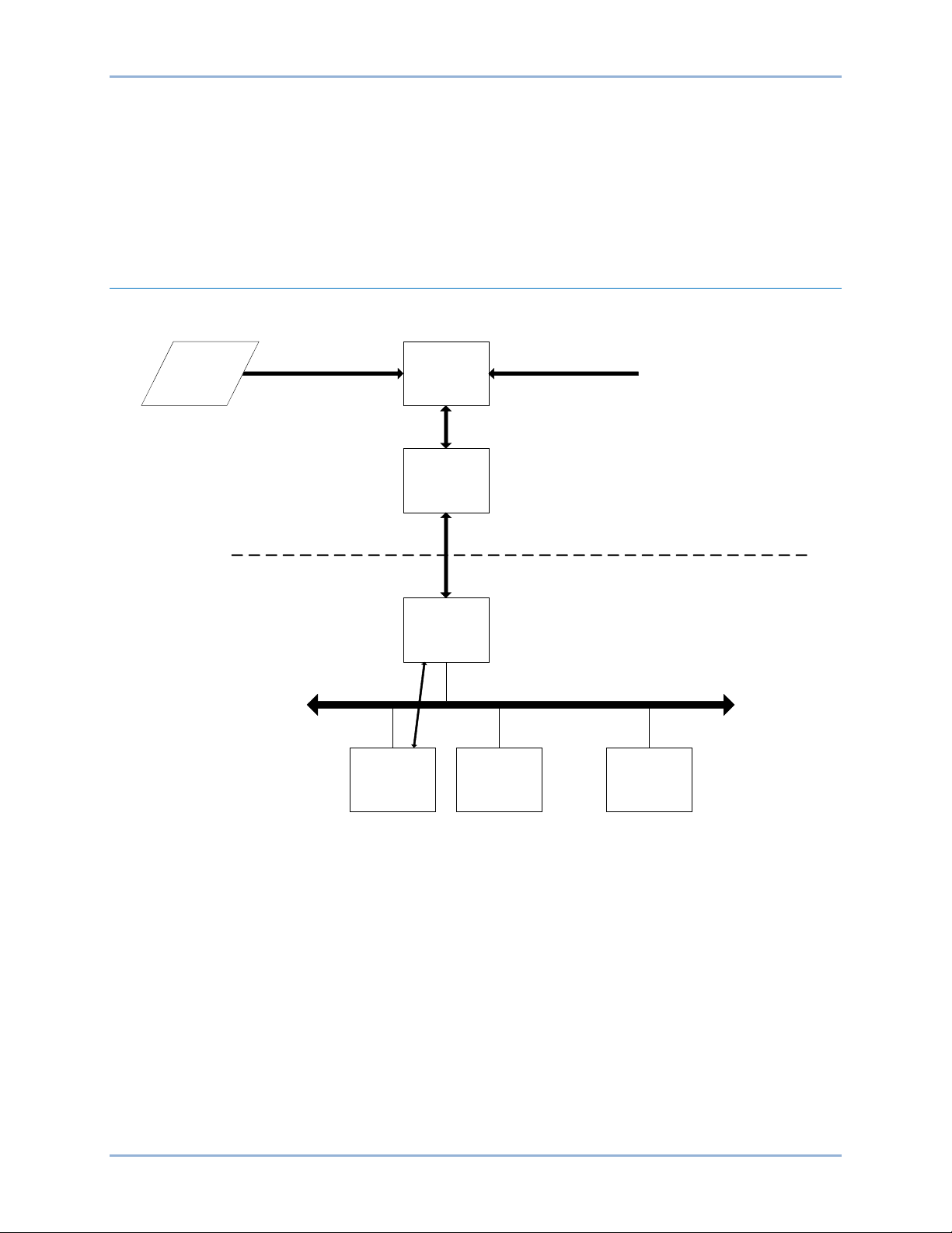
The engineering process and configuration of a substation is described in IEC 61850-Part 6:
Configuration description language for communication in electrical substations related to IEDs.
This section contains information about the standard that may be referenced when working with
BESTCOMSPlus® and BEST61850™ software.
Engineering Process in IEC 6 1 8 50
Figure 3 illustrates the reference model for information flow in the configuration process.
Figure 3. Reference Model for Information Flow in the Configuration Process
The IEC 61850 standard defines two tools and four file types for Engineering as illustrated in Figure 3.
The tools and file types are defined below.
System Configurator
The System Configurator performs the following functions:
• Imports and exports configuration files
• Imports configuration files from several IEDs for system level engineering
• Generates a substation related configuration file
• Reads an SSD file as a base for starting system engineering or for comparisons
The complete station configuration is exported in the SCD file for further use by the various IED
configuration tools.
BE1-11 IEC 61850 Engineering
Page 12

6 9424200892 Rev F
IED Configurator Tool (BEST61850™)
BEST61850 performs the following functions:
• Imports an SCD file and extracts the necessary information for each IED in the system
• Maps subscribed GOOSE messages between devices
• Configures published GOOSE messages
• Configures DataSets
• Configures Report Control Blocks (RCB)
• Creates a CID file and uploads it to the IED or exports it to a file
• Performs any additional engineering operations
ICD File (IED Capability Description File)
The capabilities of an IED are described in this file. The file contains logical node type definitions and may
contain an optional substation section.
SSD File (System Specification Description File)
This file describes the single line diagram of the substation and the required logical nodes. It contains a
substation description section and the data templates and logical node definitions.
SCD File (Substation Configuration Description File)
This file contains the data exchanged from the system configuration tool to the IED configuration tool. It
contains all IEDs, a communication configuration section, and a substation description.
CID File (Configured IED Description File)
This file contains the data exchanged from the IED configuration tool to the IED.
SCL Object Model
The SCL (Substation Configuration Language) object model consists of the following parts:
• The primary (power) system structure
• The communications system
• The application level communication
• Each IED
• Instantiable logical node (LN) type definitions
• The relations between instantiated logical nodes and their hosting IEDs on one side and the
switchyard (function) parts on the other side
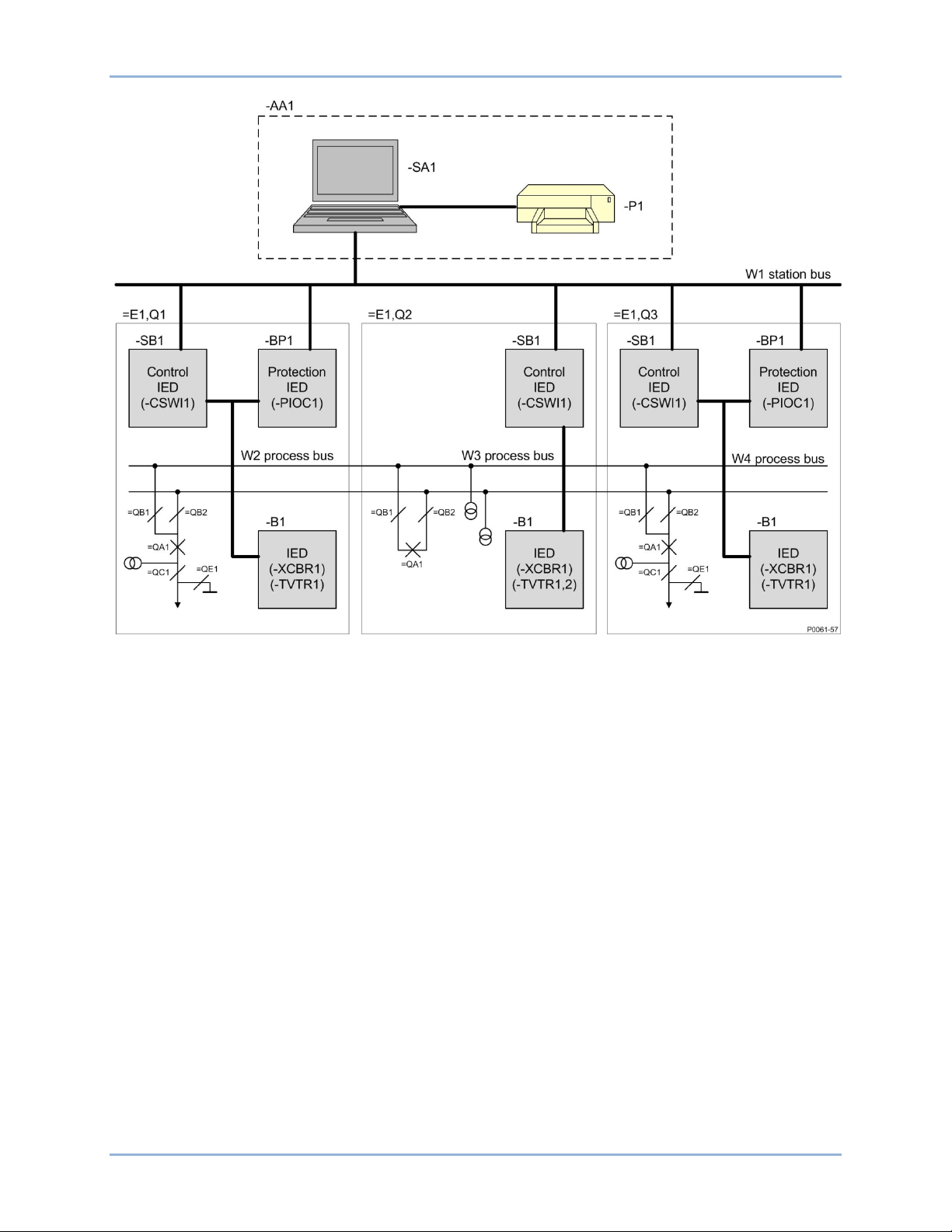
Figure 4 shows an instance of the SCL object model: a simple example of an SA (Substation
Architecture) system used for a switchyard. The switchyard has a 110 kV voltage level E1. It is a double
bus bar system with two line bays =E1Q1 and =E1Q3, and a bus coupler =E1Q2. The IEDs are already
assigned to switchyard functionality (for example the bay controller –E1Q1SB1 as a product is assigned
to bay =E1Q1, and its Logic Node CSWI1 controls the circuit breaker =E1Q1QA1 via the Logic Node
XCBR1 on the IED –E1Q1QA1B1). Figure 4 uses a – (minus) sign to indicate the product-related
designations. The functional name is not repeated. The station level communication sub network is
named W1. There are three additional sub networks at process level (W2, W3, and W4).
IEC 61850 Engineering BE1-11
Page 13
9424200892 Rev F 7
Figure 4. Configuration Example (from IEC 61850-6)
The IEC 61850 standard is based on the hierarchical addressing and informatio n mode l in a station. It
follows, in this way, the structure of the substation equipment independent of IED structure and
organization. This information and addressing model is also visible in the IEC 61850 telegrams because
the address is presented in MMS (Manufacturing Message Specification) as an ASCII string, so the
address can be seen directly in a readable form.
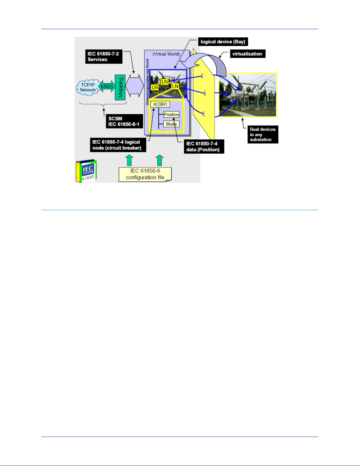
The IEC 61850 standard defines the information and its exchange in a way that it is independent of a
concrete implementation (i.e., it uses abstract models). The standard also uses the concept of
virtualization. Virtualization provides a view of those aspects of a real device that are of interest for the
information exchange with other devices. Only those details that are required to provide interoperability of
devices are defined in the IEC 61850 standard.
The approach of the standard is to decompose the application functions into the smallest entities, which
are used to exchange information. These entities are called logical nodes (for example, a virtual
representation of a circuit breaker class, with the standardized class name XCBR). Several logical nodes
build a logical device (for example, a representation of a Bay unit). A logical device is always
implemented in one IED; therefore log ical devices ar e not distr ib uted .
Real devices on the right-hand side of Figure 5 are modeled as a virtual model in the middle of the figure.
The logical nodes defined in the logical device (for example, Bay) correspond to well-known functions in
the real devices. In this example, the logical node XCBR represents a specific circuit breaker of the bay to
the right.
BE1-11 IEC 61850 Engineering
Page 14
8 9424200892 Rev F
Figure 5. Modeling Approach Example
Substation Configur a t ion Description Language (SCL)
The SCL language is based on XML (Extensible Markup Language). Detailed knowledge about an XML
file is not required, but the information within the file may be of interest. An SCL XML file is divided into
the following five sections as specified in IEC 61850-6:
• Header
• Substation description
• Communication system description
• IED description
• Data Type Templates
The Header identifies an SCL configuration file and version, and specifies options for the mapping of
names to signals. The Substation section describes the functional structure of a substation, and defines
the primary devices and their electrical connections.
Default ICD files in BEST61850 software are used to define the Header and Substation description
sections. Logical nodes of the IED are logically linked to the substation section. BEST61850 software is
used for signal engineering and routing of the signals. BESTCOMSPlus must be used to define the
substation and communication sections prior to using BEST61850. BEST61850 is used to configure the
DataSets and Control Blocks that are located in the IED section. The DataSets and Control Blocks
(Report, GOOSE, and Setting) are logically defined as part of the logical nodes per IEC 61850-7-2.
GOOSE engineering requires that BEST61850 has the correct configured Communication description
section. The Data Type Templates section gives the correct content description of each logical node type
to the clients. Logical node type definitions may vary between each IED and vendor.
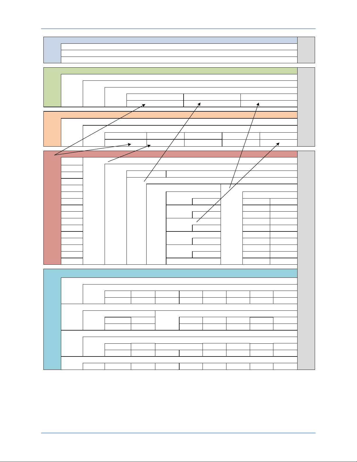
Figure 6 shows the principle structure of the SCL XML file. The arrows show the link between the different
sections given when an IED is integrated in the substation structure and/or in the communication
structure. All available logical nodes of an IED are linked to the substation section.
A reference to the GoCB (GOOSE Control Block) is included in the communication section when the
GoCB is configured. The graphical presentation of the XML file is a standard view of XML editors. It gives
a better picture about the structure of the XML contents.
IEC 61850 Engineering BE1-11
Page 15
9424200892 Rev F 9
Header
id
toolID
nameStructure
Header
Substation
Voltage Level
Bay
LNode
Station
IED
IED
LD
LD
LN
LN
Communication
Subnetwork
ConnectedAP
IED Name
IED Name
AccessPoint
AccessPoint
GSE
GSE
Address
Address
IED
AccessPoint
Server
Authentication
IED
Services
LDevice
LN0
LN
DataSet
DOI
DAI
Report Control
GOOSE Control
Inputs
DOI
Setting Control
DataTypeTemplates
LNodeType
DO
DOType
DOType
DA
DAType
SDO
DAType
BDA
EnumType
EnumType
P0061-69
BE1-11 IEC 61850 Engineering
Figure 6. Principle Structure of the SCL XML File
Page 16
10 9424200892 Rev F
LDName
LN Prefix LN Class LN Instance
#
Data Name
Data Attribute Name
Defined in IEC
61850
-7
-4
Defined in IEC
61850
-7
-
3
Configurable
LNName
P0061
-
62
Part
1 Part
2
Part 3 Part
4
BE1
_11PRO
IND GGIO
1
Ind01 stVal
LNName
BE1
-11 XML Example:
BE1
_11PRO
.INDGGIO1
$Ind
01$stVal
Signal Identification
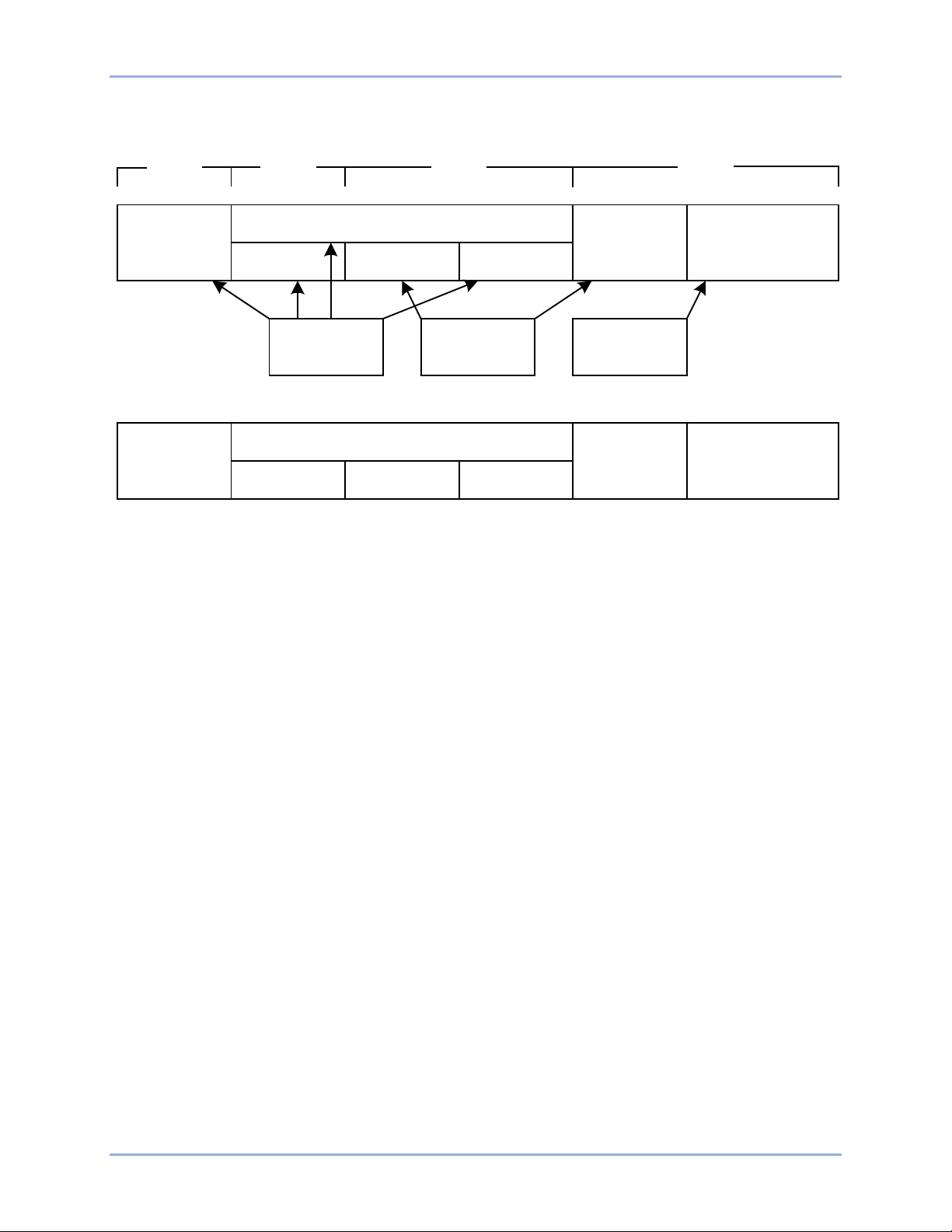
Elements of the signal identification as defined in IEC 61850–7–2 are illustrated in Figure 7.
Figure 7. Elements of the Signal Identification as Defined in IEC 61850-7-2
The signal designation consists of the following four parts:
1. A user defined part identifying the Logical Device LD in the process (LDName).
2. A function related part to distinguish several LNs of the same class within the same LD/IED (LN-
Prefix).
3. The standardized LN class name and the LN instance number, which distinguishes several LNs
of the same class and prefix within the same LD/IED.
4. A signal identification inside a LN consisting of data and attribute name as defined in IEC 61850–
7–3 and IEC 61850–7–4.
IED Related Naming
The LDName part is built out of the objects IED and LDevice. The LNName is the LN Prefix, the LN class
and the LN instance #.
The LN prefix is used to identify several versions of a LN class. The link between the IED and the primary
process (Substation, Voltage level, Bay) is given in the substation section of the station SCD file but not in
the signal identification in the telegram. The IED name may be extended with a short form of the three
missing levels. See Figure 8.
IEC 61850 Engineering BE1-11
Page 17
9424200892 Rev F 11
LN Prefix
LN Class
LN Instance #
LNName
LDName
IED Section:
Attribute Name of
element IED
IED Section:
Attribute Inst of
element LDevice
IED Section:
Attribute Inst of element LN
Defined in IEC 61850-7-4
Predefined by IED
Header:
NameStructure=”IEDName”
P0061-63
E1
Q1
QA1
SB1
LD1
LD2
LN1
LN2
LN1
LN2
W1
Voltage Level
Bay
IED
Access Point
Station Bus
S1
In the communication
structure, this connection is
identified as W1E1Q1SB1S1.
In the IED structure, this LD
is identified as-E1Q1SB1LD2.
In the IED (product)
structure, this LN is identified
as -E1Q1SB1LD2CSWI2.
In the substation structure,
this LN is identified as
=E1Q1LD2QA1CSWI2.
In the substation structure,
this CBR is identified as
=E1Q1QA1.
P00
61-
64
Figure 8. Elements of the Signal Name Using Product Naming
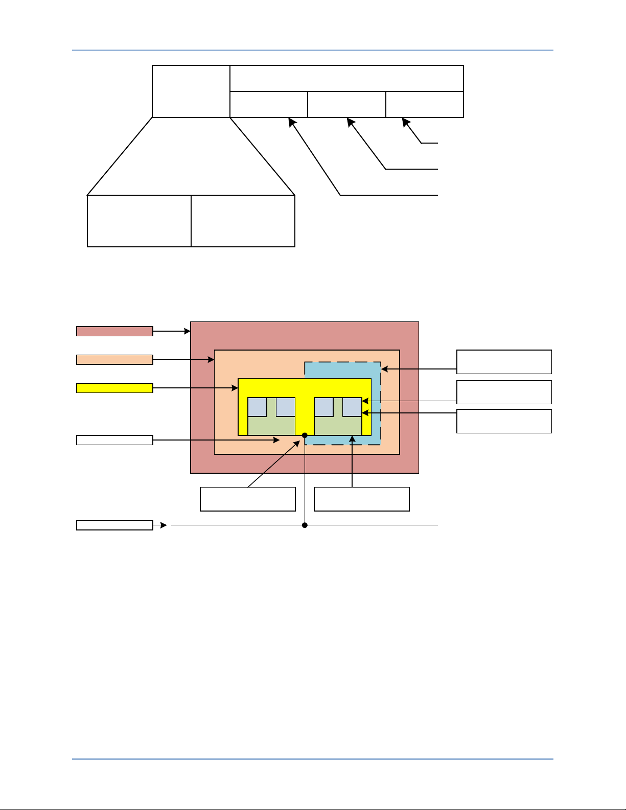
Figure 9 shows an example of an IED (SB1) with logical devices LD1 and LD2. Each logical device (LD1
and LD2) contain logical nodes LN1 and LN2, which control a circuit breaker QA1 of bay Q1 in voltage
level E1.
Figure 9. Names within Different Structures of the Object Model
Communication Network Section
The organization of the physical IEDs to the communication network is independent of the substation
structure. The IEC 61850 standard defines the communication network with no relation to an existing
media and protocol. The first mapping to an existing media and protocol is done in IEC 61850–8–1 with:
The IEC 61850 standard describes in part 7–2 the Abstract Communication Service Interface (ACSI) in a
media and protocol independent form. Part 8–1 specifies the mapping of this ACSI to the existing MMS.
The communication section in the SCL file describes the minimum of what is needed to identify how
information is routed between the IEDs in a project. This is:
BE1-11 IEC 61850 Engineering
• Ethernet as medium
• MMS (Manufacturing Message Specification) protocol as defined in ISO 9506–1 and ISO 9506–2
• the used sub networks
• the IEDs connected to the different sub networks
Page 18
12 9424200892 Rev F
IED (
client)
- Access Point (AP)
- Address
- GSE: GoCBs
IED (server)
IED (client)
- Access Point (AP)
- Address
- GSE: GoCBs
IED (server)
IED (client)
- Access Point (AP)
- Address
- GSE: GoCBs
IED (server)
IED (client)
- Access Point
(AP)
- Address
- GSE: GoCBs
IED (server)
IED (client
)
- Access Point (AP
)
- Address
- GSE: GoCBs
IED (server)
Subnetwork
AP
AP
P0061-65
• the access points per IED to the sub networks
• the address
• the IP address of the LAN network is an exception also part of the address elements
• extended during signal engineering and routing, the link to the GoCB message in transmission
direction
Figure 10 shows the IEC 61850-6: Communication Network.
Figure 10. IEC 61850-6: Communication Network
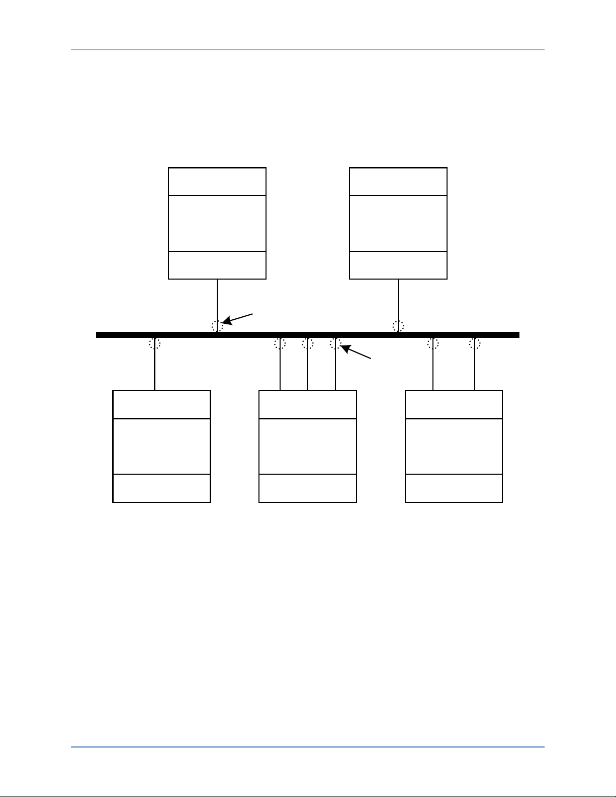
IED Section
The IED section describes the complete IED as it is needed for IEC 61850 communication. The Data
Type Template part of an IED may be seen as part of the IED, even when separated in its own section.
The IED’s ICD file includes the description of the LNs, their Data Type Templates, and the
used/supported services. The structure of the IED section follows the definitions made in the IEC 61850
standard.
Figure 11 illustrates organization of LDs, LNs, DOs, and DAs in an IED.
IEC 61850 Engineering BE1-11
Page 19
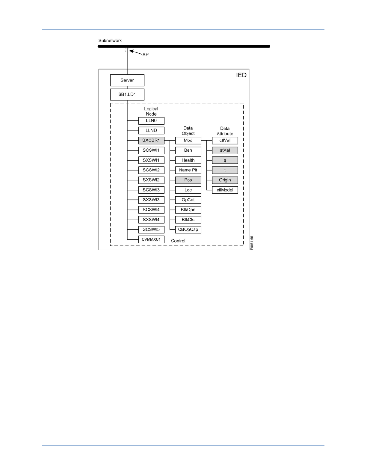
9424200892 Rev F 13
Figure 11. Organization of LDs, LNs, DOs, and DAs in an IED
An IED server represents the communication interface to the sub network (Ethernet).
• One or more Logical device(s) are connected to a server
• A set of Logical Nodes belong to a Logical Device
• The Logic Node LLN0 is a special Logic Node per Logic Device and contains the DataSets,
GOOSE Control Blocks (GoCB), Report Control Blocks (RCB), and Setting Group Control Block
(SGCB)
• The Logic Node LPHD is a special Logic Node per Logic Device and contains Data Objects (DO)
which describe the status of the physical device (the IED)
• Each Logical Node represents a function and contains a number of Data Objects (DO)
• Each DO is represented by a number of Data Attributes (DA)
The data objects are representing information signals which may be routed to station level IEDs.
The signal engineering task is to select the requested signals (DOs) and link them to the client IEDs as
receiver. The control services are not directly engineered. They are included in the data objects which
handle both directions the command (control) and the response (monitoring). When routing the DO in
monitoring direction the control is known by the clients. The organization of the IED from LD down to DAs
can be viewed in the BEST61850 tool. This organization concept must be taken into consideration when
DataSets are configured.
The number of data objects and data attributes per Logical Node is defined by the used LN type in this
IED. The contents are taken from the Data Type Templates which belong to an IED type.
BE1-11 IEC 61850 Engineering
Page 20
14 9424200892 Rev F
P
0
06
1
-6
7
LD1
LLN0
LPHD
SXCBR1
SCSWI1
SXSWI1
SCSWI
2
SXSWI2
SCSWI3
SXSWI
3
SCSWI4
SXSWI4
SCSWI5
CVMMXU1
Pos
Pos
Pos
Pos
Pos
stVal
q
t
Origin
LD1/LLN0
LD1/SXCBR1.Pos FC=ST
LD1/SXSWI1.Pos FC=ST
LD1/SXSWI2.Pos FC=ST
LD1/SXSWI3.Pos FC=
ST
LD
1/SXSWI4.Pos FC=ST
DataSet
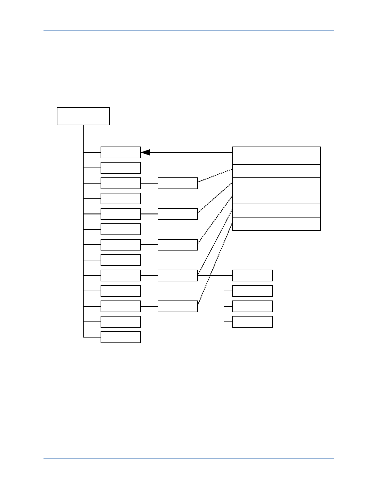
Signal Engineering
Signal engineering consists of DataSets, Report Control Blocks (RCB), and Goose Control Blocks
(GoCB).
DataSets
IEC 61850 has defined DataSets for signal transmission in Report Control Blocks. DataSets are also used
for GOOSE messages. Figure 12 shows a DataSet where all position information of the apparatuses of a
bay are put into one DataSet.
Figure 12. DataSet Example
General rules for DataSet configuration:
• All data objects or their data attributes can be selected for a DataSet.
• Only those data attributes of a data object are selected which have the same functional constraint
• Data objects with different FC can be selected for a DataSet. For example DOs with FC=ST and
• A single data attribute can be selected when it is specified with a trigger option. For example the
(FC).
DOs with FC=MX can be members in one DataSet.
data attribute stVal of the data object Pos can be selected as a member of a DataSet, because it
is specified with the trigger option data change detected (dchg).
The description of the DataSets and the list of data object members or FCDAs (Functionally Constrained
Data Attributes) is included in the SCL file in the IED section in the Logical Device subsection. FCDAs are
IEC 61850 Engineering BE1-11
Page 21

9424200892 Rev F 15
also referred to as Data Tags. As specified in IEC 61850–7–2 clause 9, the DataSets are part of a Logical
Node. They are included in the LLN0.
Report Control Blocks (RCB)
The contents of an RCB are listed in IEC 61850– 7–2 in clause 14, table 23. The RCB contains a list of
attributes which handle and secure the communication between the client and the server.
• Buffer Time - This parameter describes how long the report should wait for other expected events
before it sends the report to the client. When known, additional events are generated as a follow
up. It is useful to wait for approximately 500 ms for additional events stored in the report. This
feature reduces the number of telegrams transmitted in case of a burst of changes. But it
increases the overall transaction time for events from IED input to presentation on HMI which is
normally one second.
• Trigger Options - Data attributes have three trigger options (dchg, qchg, dupd). Within the RCB,
two others can be defined integrity and general interrogation. The attribute Trigger Option is a
multiple choice and allows masking of the supported trigger options in this RCB.
• Integrity Period - When period is selected in the trigger option attr ibut e, it is needed to define an
integrity period to force the transmission of all data listed in the DataSet. This is done by the
attribute Integrity Period. This feature can be used as a background cycle to ensure that the
process image in all partners is the same.
• General Interrogation - A general interrogation is only done on request from a client. Not all
DataSets contain information which is needed for a general update of the client. For example,
data with T(ransient) = TRUE are not part of a GI. When the RCB attribute general interrogation
is set to TRUE a GI request from the client will be handled. The report handler will transmit all
data defined in the DataSet with their actual values. The IEC 61850 standard defines that all
buffered events are transmitted first before the GI is started. A running GI is stopped and a new
GI is started, when a new GI request is received while a GI is running.
Trigger Options
IEC 61850 has defined five different TrgOp. Three of them belong to data attributes and they are marked
per data attribute in the column TrgOp of the CDC tables in part 7–3. The other two belong to the
configuration of control blocks. The five trigger options are:
• dchg = data-change - The classical trigger. Whenever a process value has changed its value
either binary or a measurement a transmission is done.
• qchg = quality change - Looking to the possibilities of the quality data attribute type (q) any
changes in the quality description are transmitted.
• dupd = data value update - This trigger option gives the possibility to define that a transmission
should be done on a condition which can be controlled by the application.
• Period - This trigger forces the transmission of all process values defined in the DataSet when a
timer value (the integrity period) expires. For example, it can be used to do a process signal
update in the background (e.g. every 15 minutes).
• General Interrogation - This trigger is forced by the clients (= station level IED; NCC gateway,
station HMI, ...). Normally a GI is asked for when the client and the server start or restart a
session. When the client is able to receive the actual values and when the Logical Device has
scanned all process values at least once, an image of the actual process signal status can be
transmitted to the client.
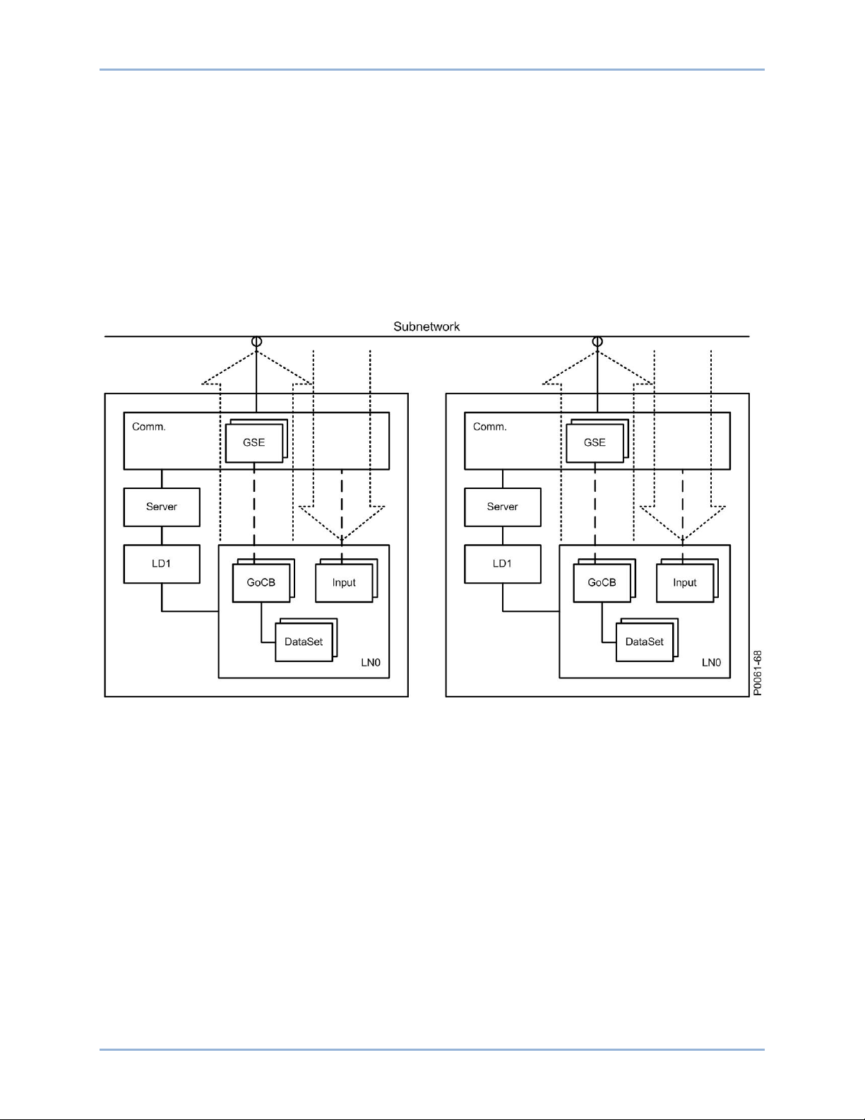
Goose Control Blocks (GoCB)
The Generic Object Oriented Substation Event (GOOSE) class model is used to distribute input and
output data values between IEDs on bay level through the use of multicast services. GOOSE messages
bypass the server which results in a fast transmission from publisher to one or several subscribers
(receivers).
The GOOSE message concept is used for all application functions where two or more IEDs are involved.
BE1-11 IEC 61850 Engineering
Page 22
16 9424200892 Rev F
To send GOOSE messages, a GoCB must be defined and a DataSet is needed which contains the data
objects of single data attributes to be sent. A GOOSE message is forced to be transmitted when a trigger
change is detected for a data attribute. All members of the DataSet will be copied in the send buffer with
their actual value and the message is sent. All subscribers which know the address of this GOOSE
message will receive the telegram. The GOOSE message includes a sequence number and a state
number to verify that all messages are received.
In the SCL communication section in the GSE element, the GoCB is listed under the ConnectedAP.
The IEDs which should receive a GOOSE message are informed in the SCL private section that they will
receive GOOSE messages. This is given when the external Reference, the name of the IED, and the
member of the DataSet is included in the LLN0 logic node under the structure of the Logic Device (LD) of
the receiving IED. The IEDs which receive the GOOSE are selected by BEST61850.
The IEC 61850 principle operation of GOOSE messages is illustrated in Figure 13.
Figure 13. IEC 61850: Principle Operation of GOOSE Messages
IEC 61850 Engineering BE1-11
Page 23
9424200892 Rev F 17
BESTCOMSPlus®
BESTCOMSPlus is a Windows®-based, PC application that provides a user-friendly, graphical user
interface (GUI) for use with Basler Electric communicating products. BESTCOMSPlus is used to program
IEC 61850 logic. It is also used to program BE1-11 operational settings and other logic. For more
information, refer to the BESTCOMSPlus Sof tware chapter in the appropriate BE1-11 instruction manual
below:
• 9424200990 - Instruction Manual for BE1-11f
• 9424200993 - Instruction Manual for BE1-11i
• 9424200994 - Instruction Manual for BE1-11g
• 9424200995 - Instruction Manual for BE1-11t
• 9424200996 - Instruction Manual for BE1-11m
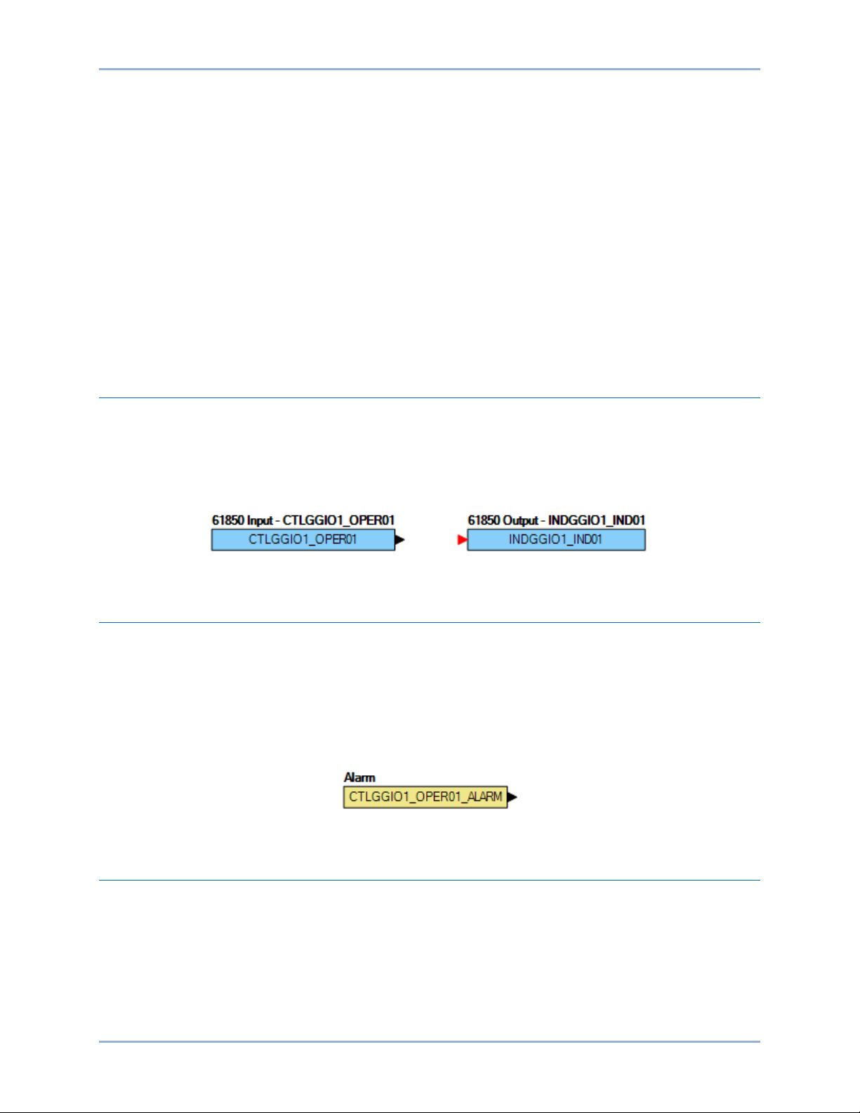
CTLGGIO OPER Output and INDGGIO OPER Input
The IEC 61850 GGIO IND outputs and OPER inputs in BESTCOMSPlus are used to map BE1-11 inputs
and outputs to IEC 61850 data points. These data points can be read directly with an IEC 61850 browser
such as IED Scout made by Omicron. The GGIO inputs and outputs can be used in an IEC 61850
DataSet which is tied to GOOSE Control Blocks (GoCB) for sending/receiving GOOSE messages.
A CTLGGIO 61850 logic output and INDGGIO logic input are shown in Figure 14.
Figure 14. 61850 Logic Output and Input
CTLGGIO OPER Alarm
The CTLGGIO OPER ALARM is set if the device has subscribed to a GOOSE message, mapped it to the
corresponding CTL GGIO, and the device has not received the subscribed GOOSE message within the
TTL (Time To Live). The TTL for the next reception is included within a GOOSE message. If the TTL timer
expire and the alarm is set, the CTLGGIO OPER logic input will switch over to the default that is
configured within the BE1-11 settings. If the device starts receiving GOOSE messages again, the alarm
will be reset and the CTLGGIO OPER logic input will be set to the value in the GOOSE message.
A CTLGGIO 61850 logic output and INDGGIO logic input are shown in Figure 14.
Figure 15. CTLGGIO Alarm
IEC61850PTRC Logic Block
The IEC61850PTRC logic block is available to set the corresponding status outputs in the IEC61850
PTRC node. The trip output for the BE1-11 should be connected to the Operate-General input of the
block. If trip statuses of individual phases are known, use BESTlogic™Plus to connect them to the Phase
A, Phase B, and Phase C logic inputs.
The IEC 61850 PTRC logic block is shown in Figure 16.
BE1-11 BESTCOMSPlus®
Page 24

18 9424200892 Rev F
Figure 16. IEC61850PTRC Logic Block
BESTCOMSPlus® BE1-11
Page 25

9424200892 Rev F 19
BEST61850™
BEST61850 is a Windows®-based, PC application that provides a user-friendly, graphical user interface
(GUI) for use with Basler Electric communicating products. The name BEST61850 is an acronym that
stands for Basler Electric Software Tool for IEC 61850.
BEST61850 provides the user with a point-and-click means to configure IEC 61850 settings for the
BE1-11. BEST61850 performs the following tasks:
• Reads a SCD file and extracts the CID file
• Downloads/uploads a CID file from/to the BE1-11
• Opens a CID file from a PC or network location
• Configures IED network settings
• Configures datasets for report control blocks (RCB) and GOOSE control blocks (GoCB)
• Creates and configures Report Control Blocks (RCB)
• Maps GOOSE messages between IED subscribers
• Creates and configures GoCB for each GOOSE message
• Exports a CID file to a PC or network location
Installation
BEST61850 software is built on the Microsoft® .NET Framework. The setup utility that installs
BEST61850 on your PC also installs the required version of .NET Framework (if not already installed).
BEST61850 operates with systems using Windows® XP 32-bit SP3, Windows Vista 32-bit SP1 (all
editions), Windows 7 32-bit (all editions), Windows 7 64-bit (all editions), and Windows 8. System
recommendations for the .NET Framework and BEST61850 are listed in Table 2.
Table 2. System Recommendations for BEST61850 and the .NET Framework
System Type Component Recommendation
32-/64-bit Processor 2.0 GHz
32-/64-bit RAM 1 GB (minimum), 2 GB (recommended)
32-bit Hard Drive 30 MB (if .NET Framework is already installed on PC)
880 MB (if .NET Framework is not already installed on PC)
64-bit Hard Drive 30 MB (if .NET Framework is already installed on PC)
2.1 GB (if .NET Framework is not already installed on PC)
To install BEST61850, a Windows user must have Administrator rights.
Install BEST61850™
NOTE
Do not connect a USB cable until setup completes successfully. Connecting a
USB cable before setup is complete may result in unwanted or unexpected
errors.
BE1-11 BEST61850™
Page 26

20 9424200892 Rev F
1. Insert the BEST61850 CD-ROM into the PC CD-ROM drive.
2. When the BEST61850 Setup and Documentation CD menu appears, click the Install button for
the BEST61850 application. The setup utility installs BEST61850, the .NET Framework (if not
already installed), and the USB driver on your PC.
When BEST61850 installation is complete, a Basler Electric folder is added to the Windows programs
menu. This folder is accessed by clicking the Windows Start button and then accessing the Basler Electric
folder in the Programs menu. The Basler Electric folder contains an icon that starts BEST61850 when
clicked.
Menu Bar
The menu bar located near the top of the BEST61850 screen (see Figure 17) has four pull-down menus.
The menu bar is described in Table 3.
Table 3. Menu Bar (BEST61850)
Menu Item Description
File
New Workspace Creates a new workspace
Open Workspace Opens a saved workspace
Save Workspace Saves the workspace
Save Workspace As Saves the workspace with a different file name
Open SCL File Opens a CID, ICD, or SCD file
Exit Closes BEST61850 software
View
Workspace Opens the Workspace window
Status Opens the Status window
Default Layout Opens both the Workspace and the Status windows
Communication
Download CID From Device Downloads a CID file from the device
Help
Check for Updates Check for BEST61850 updates via the internet
Check for Update Settings Enable or change automatic checking for updates
About View general, detailed build, and system information
BEST61850™ Settings
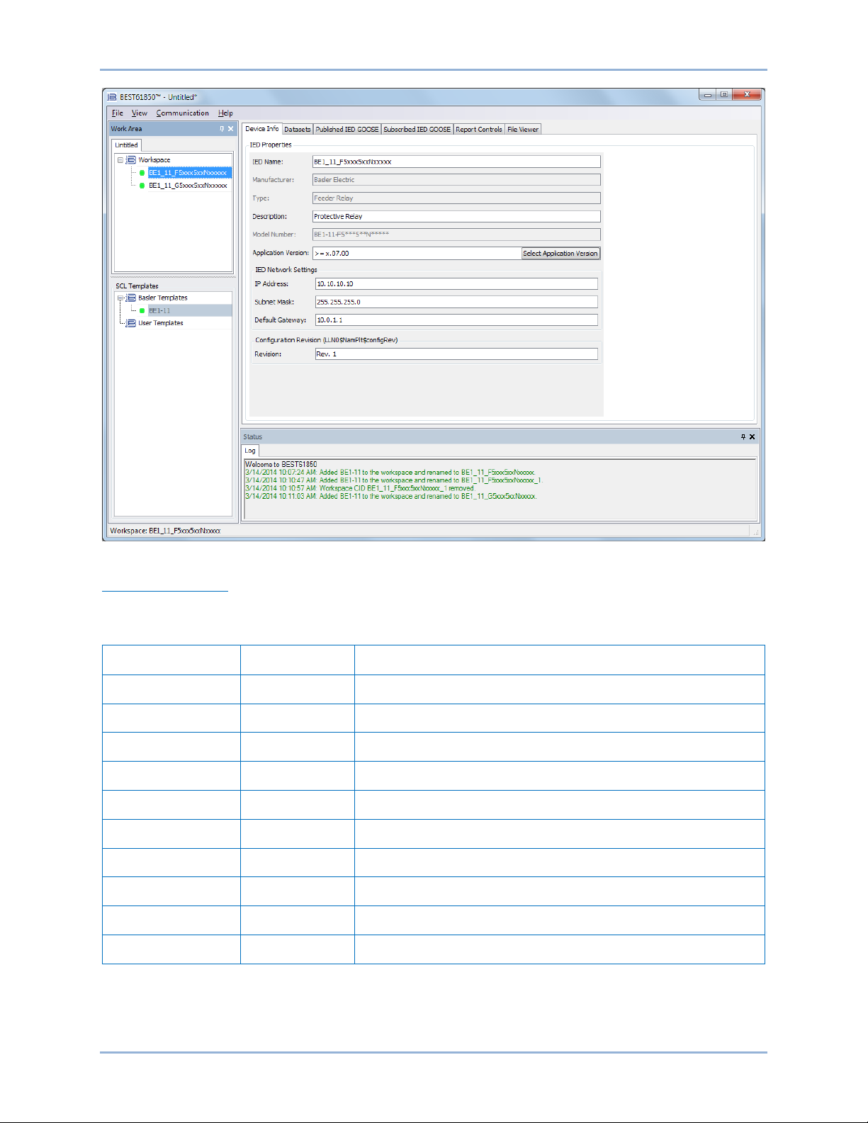
Device Info
The Device Info tab is illustrated in Figure 17.
BEST61850™ BE1-11
Page 27
9424200892 Rev F 21
Figure 17. Device Info Tab
Device Info Settings
The Device Info settings are described in Table 4.
Table 4. Device Info Settings
Setting Range Description
IED Name String (32) Name of IED (only alphanumeric and underscore characters)
Manufacturer n/a Manufacturer of the IED (read only)
Type n/a Type of IED (read only)
Description String (255) Description of IED (not sent to IED, only saved in BEST61850)
Model Number n/a BE1-11 Style Number
Application Version n/a BE1-11 firmware application verison
IP Address Dotted Decimal IP Address of IED
Subnet Mask Dotted Decimal Subnet Mask of IED
Default Gateway Dotted Decimal Default Gateway of IED
Revision n/a Configuration revision
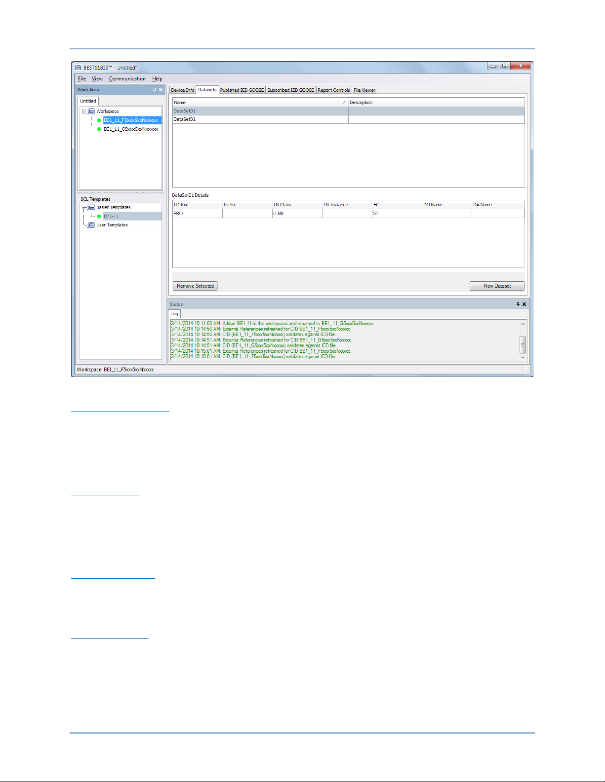
Datasets
The Datasets tab is illustrated in Figure 18.
BE1-11 BEST61850™
Page 28
22 9424200892 Rev F
Figure 18. Datasets Tab
Functional Constraints
The IEC 61850 standard defines a number of functional constraints that indicate the data attribute is used
for some particular purpose, such as reporting (BR/RP), configuration (CF), control (CO), description
(DC), extended definition (EX), GOOSE control (GO), logging (LG), measured analog value (MX), setting
groups (SG), setpoint (SP), and status (ST). The functional constraints of a DATA instance determines
the rights of services to read and/or write the DATA.
DATA OBJECT
The DATA OBJECT or DATA class (abbreviated DO) like the LN class, is a key element of the IEC 61850
standard. Values of DATA instances represent meaningful information about substation devices, such as
currents, voltages, power, phases, temperatures, status, timestamps, and so on. The DATA OBJECT
may contain attributes which are themselves instances of the DATA class. Hence, it can be said that the
DATA class is recursively defined.
DATA ATTRIBUTE
The DATA ATTRIBUTE class (abbreviated DA) contains the smallest piece of data that can be defined in
IEC 61850. The DA class includes definition of instance name, reference, type, and presence. Presence
indicates whether or not the data is mandatory or optional.
Datasets Settings
The Datasets settings are described in Table 5.
BEST61850™ BE1-11
Page 29
9424200892 Rev F 23
Table 5. Datasets Settings
Setting Range
LDevice Inst List selectable
Logical Node List selectable
FC List selectable
DO Name List selectable
DA Name List selectable
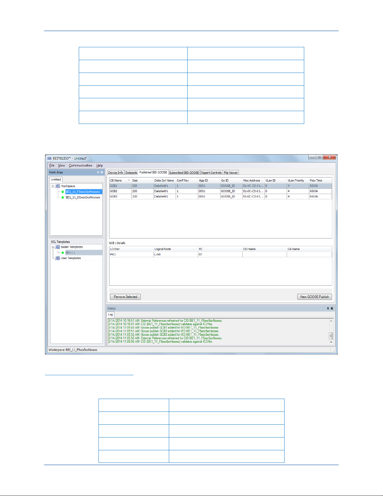
Published IED GOOSE
The Published IED GOOSE tab is illustrated in Figure 19.
Figure 19. Published IED GOOSE Tab
Published IED GOOSE Settings
The Published IED GOOSE settings are described in Table 6.
Table 6. Published IED GOOSE Settings
Setting Range
GOOSE Control Name String (65)
Dataset String (255)
Configuration Revision 1 to 65535
APPID 00 to FF
BE1-11 BEST61850™
Page 30

24 9424200892 Rev F
Setting Range
GoID String (65)
MAC Address 00 to FF (per each hexadecimal group)
VLAN ID 000 to FFF
VLAN Priority 0 to 7
Max Time 1 to 65536
Subscribed IED GOOSE
The Subscribed IED GOOSE tab is illustrated in Figure 20.
Figure 20. Subscribed IED GOOSE Tab
Subscribed IED GOOSE Settings
The Subscribed IED GOOSE settings are described in Table 7.
Table 7. Subscribed IED GOOSE Settings
Setting Range
Source
IED Name List selectable
LDevice Inst List selectable
GOOSE Block List selectable
BEST61850™ BE1-11
Page 31

9424200892 Rev F 25
Mapped To
Setting Range
Dataset List selectable
Data Tags List selectable
IED Name List selectable
LDevice Inst List selectable
Logical Node List selectable
FC CO
DO Name List selectable
DA Name Oper.ctlVal
Report Controls
The Report Controls tab is illustrated in Figure 21.
Figure 21. Report Controls Tab
Reporting is handled by the REPORT-CONTROL-BLOCK class of the ACSI. This class controls the
procedures that are required for reporting values of DATA from one or more LNs to one client.
Three trigger options (data-change, quality-change, and data-update) can cause a report to be sent to a
client. Report control is divided into two classes: BUFFERED-REPORTCONTROLBLOCK (abbreviated
BRCB) and UNBUFFERED-REPORT-CONTROLBLOCK abbreviated (URCB).
BE1-11 BEST61850™
Page 32

26 9424200892 Rev F
The class BRCB allows for the sending of reports to be issued immediately, or for the events to be
buffered for transmission af ter an amount of t ime specified by the Buffered Time setting. Furthermore,
BRCB provides the sequence-of-events (SOE) functionality. If the connection is broken when reporting is
to take place, the report is buffered and sent when the connection is re-established.
The class URCB only allows transmission of reports according to the time specified by the Buffered Time
setting. If the connection is lost, buffering is terminated and the reports are discarded. URCB does not
provide SOE functionality.
For both types of reporting, the server must restrict access to an instance of a report control block to one
client at a time. The client will be associated with the control block and that client will be the only one
receiving reports from the control until the association is released or aborted. In order for more than one
client to receive reports of the same values of DATA, multiple instances of the report control block classes
must be made available. (The BE1-11 contains four instances.) It is also defined in the standard how this
should be achieved. In this context, it must be discerned between buffered reporting and unbuffered
reporting.
In the case of buffered reporting, it is important that a client, whose connection is lost in the middle of the
transmission of the report, is associated with the same report control instance the next time the client
reconnects. For this reason, the report control can keep track of which report was successfully transmitted
last, and thus, which reports are yet to be transmitted. For unbuffered reporting, this is not necessary. The
class provides services for sending a buffered report and reading or writing attributes of a BRCB.
Figure 17 illustrates the client/server interface for RCB Reports.
Figure 22. Client/Server Interface for RCB Repo rts
Report Controls Settings
The Report Controls settings are described in Table 8.
BEST61850™ BE1-11
Page 33

9424200892 Rev F 27
Table 8. Report Controls Settings
Setting Range
Report ID n/a
Name String (65)
Configuration Revision 1 to 65535
DataSet String
Integrity Period 0 to 65535
Buffered
True (Buffered) or False
(Unbuffered)
Buffered Time 0 to 65535
Report Enabled Max 1 to 4
Trigger Options: Data Change, Quality Change, Data Uploaded, Period check box selectable
Optional Fields: Sequence Number, Time Stamp, DataSet, Reason Code,
check box selectable
Data Reference, Entry ID, Configuration Revision
File Viewer
The File Viewer tab is illustrated in Figure 23. Click on to collapse the branches. Click on to expand
the branches.
Figure 23. File Viewer Tab
BE1-11 BEST61850™
Page 34

28 9424200892 Rev F
Configuration Exampl e
This configuration example provides step-by-step instructions on how to configure two separate CIDs.
Configure Communication Parameters and Names
Step 1: Start BEST61850 software.
Step 2: Using the mouse, left-click on and hold the BE1-11 SCL Tem pla te. Wh ile hold ing down the lef t
mouse button, drag the template into the Workspace area and release. See Figure 24.
Step 3: The BE1-11 BEST61850 Template Selection screen appears as shown in Figure 25. Use the
drop-down buttons to select the style number of the BE1-11 and click OK.
Step 4: Under IED Properties, enter BE1_11_1 for IED Nam e and Protective Relay 1 for Description.
Enter the IED Network Settings for the IED being configured.
Step 5: The CID should be validated against the ICD file before proceeding. Right-click on the
BE1_11_1 file in the Workspace and select Validate. The round indicator located on the left
side of the file name changes from yellow to green if validation is successful.
Step 6: Repeat Steps 2 and 3 to add a second SCL Template to the Workspace. See Figure 26.
Step 7: Under IED Properties, enter BE1-11_2 for IED Name and Protective Relay 2 for Description.
Enter the IED Network Settings for the IED being configured.
Step 8: Right-click on the BE1_11_2 file in the Workspace and select Validate. The round indicator
located on the left side of the file name changes from yellow to green if validation is successful.
Figure 24. Adding an SCL Template to the Workspace
BEST61850™ BE1-11
Page 35

9424200892 Rev F 29
Figure 25. BE1-11 BEST61850 Template Selection Screen
Figure 26. Adding a Second SCL Template to the Workspace
Configure DataSets
Step 1: Select the DataSets tab in BEST61850. See Figure 27. A maximum of 16 DataSets is allowed.
Step 2: Highlight the BE1_11_1 file in the Workspace and click the New Dataset button. The Add New
Dataset screen appears. See Figure 28.
Step 3: Enter a dataset description and select PRO$INDGGIO1$ST$Ind01$stVal by selecting the
individual parts of the FCDA (Functionally Constrained Data Attribute) information as shown in
Figure 28. The FC (Functional Constraint) is automatically set to ST.
Step 4: Click the Add button to add the FCDA information to the current FCDA.
Step 5: Click the Add button in the lower-right corner of the Add New Dataset window.
BE1-11 BEST61850™
Page 36

30 9424200892 Rev F
Step 6: Right-click on the BE1_11_1 file in the Workspace and select Validate. The round indicator
located on the left side of the file name changes from yellow to green if validation is successful.
Step 7: Repeat Steps 1 through 5 to configure DataSet02 using a different FCDA in Step 3.
Step 8: Repeat Steps 1 through 7 to configure the DataSets for the BE1_11_2 CID file.
Figure 27. Datasets Tab
Figure 28. Add New Dataset Screen
BEST61850™ BE1-11
Page 37

9424200892 Rev F 31
Configure Published IED GOOSE
Step 1: Select the Published IED GOOSE tab in BEST61850. See Figure 29. A maximum of four
Published IED GOOSE messages is allowed.
Step 2: Highlight the BE1_11_1 file in the Workspace. Click the New GOOSE Publish button. The Add
New Published GOOSE screen appears. See Figure 30.
Figure 29. Published IED GOOSE Tab
Figure 30. Add New Published GOOSE Screen
Step 3: Make the appropriate settings as shown in Table 9 and click the Add button.
BE1-11 BEST61850™
Page 38

32 9424200892 Rev F
Table 9. Published IED GOOSE Example Values
Setting Range Value
GOOSE Control Name String (65) GCB1
Dataset String (255) DataSet01
Configuration Revision 1 to 65535 1
App ID 00 to FF 0001
Go ID String (65) testgoose
MAC Address 00 to FF (per each hexadecimal group) 01-0C-CD-01-00-01
VLAN ID 000 to FFF 0
VLAN Priority 0 to 7 0
Max Time 1 to 65536 20000
Step 4: Right-click on the BE1_11_1 file in the Workspace and select Validate. The round indicator
located on the left side of the file name changes from yellow to green if validation is successful.
Step 5: Repeat Steps 1 through 4 to configure additional Published IED GOOSE messages.
Configure Subscribed IED GOOSE
Step 1: Select the Subscribed IED GOOSE tab in BEST61850. See Figure 31. A maximum of 20
Subscribed IED GOOSE messages is allowed.
Step 2: Highlight the BE1_11_2 file in the Workspace. Click the New GOOSE Subscribe button. The
Add New Subscribed GOOSE screen appears. See Figure 32.
Step 3: Make the appropriate settings changes by selecting the Source IED (BE1_11_1) Data Tags
(INDGGIO1$Ind01$stVal) Mapped To (BE1_11_2) FCDA
CTLGGI01$CO$SPCSO1$Oper$ctlVal and click the Add button.
Step 4: Right-click on the BE1_11_2 file in the Workspace and select Validate. The round indicator
located on the left side of the file name changes from yellow to green if validation is successful.
Step 5: Repeat Steps 1 through 4 to configure additional Subscribed IED GOOSE messages.
BEST61850™ BE1-11
Page 39

9424200892 Rev F 33
Figure 31. Subscribed IED GOOSE Tab
Figure 32. Add New Subscribed GOOSE Screen
Configure Report Control Blocks
Step 1: Select the Report Controls tab in BEST61850. See Figure 33. A maximum of eight Report
Control Blocks is allowed.
Step 2: Highlight the BE1_11_1 file in the Workspace.
Step 3: Click the New Report Control button. The Add New Report Control screen appears. See Figure
34.
BE1-11 BEST61850™
Page 40

34 9424200892 Rev F
Figure 33. Report Controls Tab
Figure 34. Add New Report Control Screen
Step 4: Make the appropriate settings as shown in Table 10 and click the Add button.
Step 5: Right-click on the BE1_11_1 file in the Workspace and select Validate. The round indicator
located on the left side of the file name changes from yellow to green if validation is successful.
Step 6: Repeat Steps 1 through 5 to configure additional Report Control Blocks.
BEST61850™ BE1-11
Page 41

9424200892 Rev F 35
Table 10. Report Controls Settings Example Values
Setting Range Value
Report ID n/a BE1_11_1PRO/LLNO$bcrb1
Name String (65) bcrb1
Configuration Revision 1 to 65535 1
DataSet String DataSet01
Integrity Period 0 to 65535 5000
Buffered
Buffered Time 0 to 65535 1000
Report Enabled Max 1 to 4 1
Trigger Options: Data Change (√), Quality
Change (√), Data Uploaded (√), Period ( )
Optional Fields: Sequence Number (√), Time
Stamp (√), DataSet (√), Reason Code (√), Data
Reference ( ), Entry ID (√), Configuration
Revision
True (Buffered) or
False (Unbuffered)
check box
selectable
check box
selectable
True
N/a
N/a
BE1-11 BEST61850™
Page 42

36 9424200892 Rev F
Save a CID File as a User Template
Using the mouse, left-click on and hold the BE1_11_1 file in the Workspace. While holding down the left
mouse button, drag the file under User Templates and release. A dialog box will pop up asking you to
enter a template name. A unique name must be entered or an error will occur. See Figure 35.
Figure 35. Save a CID as a User Template
BEST61850™ BE1-11
Page 43

9424200892 Rev F 37
Save a CID File
Right-click on the BE1_11_1 file in the Workspace and select Save CID. See Figure 36.
Figure 36. Save a CID File
BE1-11 BEST61850™
Page 44

38 9424200892 Rev F
Upload a CID File to the BE1-11
Right-click on the BE1_11_1 file in the Workspace and select Upload. See Figure 37.
Figure 37. Upload a CID File to the BE1-11
Measurement Logic Node Configuration
The MMXU, IGMMXU, IABCMMXU, VXMMXN, and MSQI measurement (metering) logic nodes have
Functional Constraint (FC) Configuration (CF) data attributes used to identify the control model (ctlModel),
metering unit (units), scale (multip lier) , and dea dba nd ( db) of the meter ed log ic node. See Figure 38.
Figure 38. IGMMXN and VXMMXN Measurement Node Configuration Data Attributes
BEST61850™ BE1-11
Page 45

9424200892 Rev F 39
Value
Definition
0
status-only
1
direct-with-normal-security
2
sbo-with-normal-security
3
direct-with-enhanced-security
4
sbo-with-enhanced-security
Value
Quantity
Unit name
Symbol
1
None
dimensionless
none 2 Length
meter
m 3 Mass
kilogram
kg 4 Time
second
s 5 Current
ampere
A 6 Temperature
Kelvin
K
7
Amount of substance
mole
mol
8
Luminous intensity
candela
cd 9 Plane angle
degrees
deg
10
Plane angle
radian
rad
11
Solid angle
steradian
sr
21
Absorbed dose
Gray (J/Kg)
Gy
22
Activity
becquerel (l/s)
q
23
Relative temperature
degrees Celsius
°C
24
Dose equivalent
sievert (J/kg)
Sv
25
Electric capacitance
farad (C/V)
F
26
Electric charge
coulomb (AS)
C
27
Electric conductance
siemens (A/V)
S
28
Electric inductance
henry (Wb/A)
H
29
Electric potential
volt (W/A)
V
30
Electric resistance
ohm (VA)
Ω
31
Energy
joule (N m)
J
32
Force
newton (kg m/s2)
N
33
Frequency
hertz (1/s)
Hz
34
Illuminance
lux (lm/m2)
lx
35
Luminous flux
lumen (cd sr)
Lm
36
Magnetic flux
weber (V s)
Wb
37
Magnetic flux density
tesl a (Wb/m2)
T
38
Power
watt (J/s)
W
39
Pressure
pascal (N/m2)
Pa
41
Area
square meter (m2)
m2
42
Volume
cubic meter (m3)
m3
43
Velocity
meters per second (m/s)
ms-1
44
Acceleration
meters per second2 (m/s2)
ms-2
45
Volumetric flow rate
cubic meters per second (m3/s)
m3s-1
46
Fuel efficiency
meters/cubic meter (m/m3)
m/m3
The ctlModel enumeration lists a control type for values listed in Table 11.
Table 11. ctlModel Symbols
The SIUnit enumeration lists an International Standard Unit symbol for values listed in Table 12.
Table 12. SIUnit Symbols
BE1-11 BEST61850™
Page 46

40 9424200892 Rev F
Value
Quantity
Unit name
Symbol
47
Moment of mass
kilogram meter (kg m)
M
48
Density
kilogram/cubic meter (kg/m3)
kg/m3
49
Viscosity
meter square/second (m2/s)
m2/s
50
Thermal conductivity
watt/meter Kelvin (W/m K)
W/m K
51
Heat capacity
joule/Kelvin (J/K)
J/K
52
Concentration
parts per million
ppm
53
Rotational speed
rotations per second (1/s)
s-1
54
Angular velocity
radian per second (rad/s)
rads-1
61
Apparent power
volt ampere (VA)
VA
62
Real power
watts (I2R)
Watts
63
Reactive power
volt ampere reactive (VISinØ)
VAr
64
Phase angle
degrees
Phi
65
Power factor
(dimensionless)
Cos (Phi)
66
Volt seconds
volt seconds (Ws/A)
Vs
67
Volts squared
volt square (W2/A2)
V2
68
Amp seconds
amp second (As)
As
69
Amps squared
amp square (A2)
A2
70
Amps squared time
amp square second (A2s)
A2t
71
Apparent energy
volt ampere hours
VAh
72
Real energy
watt hours
Wh
73
Reactive energy
volt ampere reactive hours
VArh
74
Magnetic flux
volts per hertz
V/Hz
Value
Quantity
Unit name
Symbol
-24
10
-24
Yocto
y
-21
10
-21
Zepto
z
-18
10
-18
Atto a -15
10
-15
Femto
f
-12
10
-12
Pico
p
-9
10-9
Nano
n
-6
10-6
Micro
µ
-3
10-3
Milli m -2
10-2
Centi
c
-1
10-1
Deci d 0 1 1
101
Deca
da 2 102
Hecto
h 3 103
Kilo k 6
106
Mega
M 9 109
Giga G 12
1012
Tera T 15
1015
Peta P 18
1018
Exa E 21
1021
Zetta
Z
24
1024
Yotta
Y
The multipler enumeration lists a scale symbol for values listed in Table 13.
Table 13. Multiplier Symbols
BEST61850™ BE1-11
Page 47

9424200892 Rev F 41
The deadband settings represent the deadband values used to determine when the measurement lo gic
nodes “mag” and “cVal” values update. The deadband value is based on a deadband calculation from the
instMag as shown in Figure 39. The value of mag is updated to the current value of instMag when the
value has changed according to the configuration parameter db.
Figure 39. Deadband Calculation
Figure 40. IGMMXN, VXMMXN, and IABCMMXU Measurement Node Mag Data Attributes
The deadband “value represents the percent age of diff er ence bet we en max and min in units of 0.001%”.
The range of deadband in the BE1-11 is 1 to 100,000 (0.001% to 100.000%). T he defa ult dea dba nd (d b)
settings for BE1-11 measurement logic nodes are 1.0% or value +1000.
The deadband value can be changed by an IEC 61850 client or by modifying the CID file.
BE1-11 BEST61850™
Page 48

42 9424200892 Rev F
Parameter
Limit
Description
Maximum number of DataSets
16
Max number of different named DataSets
Maximum number of bytes for
single Goose Message
1400
Max number of bytes allowed in one Goose Message
from selected DataSets
Maximum number of Published
Goose Messages
4
Max number of sent Goose Control Blocks messages
Maximum number of Subscribed
Goose Messages
20
Max number of received Goose Messages mapped to
Single Point Control SPCSO# inputs
Maximum number of Report
Control Blocks supported
8
Max number of configured reports a single client can
request
Maximum number of Clients per
(Report Enabled Max)
4
Max number of different clients that can request Report
RCB
Figure 41. MMXUN and MSQI Measurement Node Default Deadband Values
Table 14. Summary of BE1-11 IEC 61850 Parameter Limits
Control Blocks
BEST61850™ BE1-11
Page 49

9424200892 Rev F 43
Description
File Naming Conventions
Fault Record
RO-xxx_SUM.txt
Load Profile
LP-xx.cfg
LP-xx.dat
Oscillographic Records
RO-xxx.cfg
RO-xxx.hdr
Sequence of Events Report
RO-xxx_SEQ.txt
File Transfer
The BE1-11 can transmit the files listed in Table 15 when requested by a supported IEC 61850 client.
Table 15. Files Transmitted by the BE1-11
RO-xxx.dat
BE1-11 File Transfer
Page 50

44 9424200892 Rev F
File Transfer BE1-11
Page 51

9424200892 Rev F 45
Data Tags
CTLGGIO1.CF.Mod.ctlModel
CTLGGIO1.CF.SPCSO1.ctlModel
CTLGGIO1.CF.SPCSO10.ctlModel
CTLGGIO1.CF.SPCSO11.ctlModel
CTLGGIO1.CF.SPCSO12.ctlModel
CTLGGIO1.CF.SPCSO13.ctlModel
CTLGGIO1.CF.SPCSO14.ctlModel
CTLGGIO1.CF.SPCSO15.ctlModel
CTLGGIO1.CF.SPCSO16.ctlModel
CTLGGIO1.CF.SPCSO2.ctlModel
CTLGGIO1.CF.SPCSO3.ctlModel
CTLGGIO1.CF.SPCSO4.ctlModel
CTLGGIO1.CF.SPCSO5.ctlModel
CTLGGIO1.CF.SPCSO6.ctlModel
CTLGGIO1.CF.SPCSO7.ctlModel
CTLGGIO1.CF.SPCSO8.ctlModel
CTLGGIO1.CF.SPCSO9.ctlModel
CTLGGIO1.CO.SPCSO1.Oper.ctlVal
CTLGGIO1.CO.SPCSO10.Oper.ctlVal
CTLGGIO1.CO.SPCSO11.Oper.ctlVal
CTLGGIO1.CO.SPCSO12.Oper.ctlVal
CTLGGIO1.CO.SPCSO13.Oper.ctlVal
CTLGGIO1.CO.SPCSO14.Oper.ctlVal
CTLGGIO1.CO.SPCSO15.Oper.ctlVal
CTLGGIO1.CO.SPCSO16.Oper.ctlVal
CTLGGIO1.CO.SPCSO2.Oper.ctlVal
CTLGGIO1.CO.SPCSO3.Oper.ctlVal
CTLGGIO1.CO.SPCSO4.Oper.ctlVal
CTLGGIO1.CO.SPCSO5.Oper.ctlVal
CTLGGIO1.CO.SPCSO6.Oper.ctlVal
CTLGGIO1.CO.SPCSO7.Oper.ctlVal
CTLGGIO1.CO.SPCSO8.Oper.ctlVal
CTLGGIO1.CO.SPCSO9.Oper.ctlVal
CTLGGIO1.DC.NamPlt.d
CTLGGIO1.DC.SPCSO1.d
CTLGGIO1.DC.SPCSO10.d
CTLGGIO1.DC.SPCSO11.d
CTLGGIO1.DC.SPCSO12.d
CTLGGIO1.DC.SPCSO13.d
Data Tags
CTLGGIO1.DC.SPCSO14.d
CTLGGIO1.DC.SPCSO15.d
CTLGGIO1.DC.SPCSO16.d
CTLGGIO1.DC.SPCSO2.d
CTLGGIO1.DC.SPCSO3.d
CTLGGIO1.DC.SPCSO4.d
CTLGGIO1.DC.SPCSO5.d
CTLGGIO1.DC.SPCSO6.d
CTLGGIO1.DC.SPCSO7.d
CTLGGIO1.DC.SPCSO8.d
CTLGGIO1.DC.SPCSO9.d
CTLGGIO1.ST.Beh.q
CTLGGIO1.ST.Beh.stVal
CTLGGIO1.ST.Beh.t
CTLGGIO1.ST.Health.q
CTLGGIO1.ST.Health.stVal
CTLGGIO1.ST.Health.t
CTLGGIO1.ST.Mod.q
CTLGGIO1.ST.Mod.stVal
CTLGGIO1.ST.Mod.t
CTLGGIO1.ST.SPCSO1.q
CTLGGIO1.ST.SPCSO1.stVal
CTLGGIO1.ST.SPCSO1.t
CTLGGIO1.ST.SPCSO10.q
CTLGGIO1.ST.SPCSO10.stVal
CTLGGIO1.ST.SPCSO10.t
CTLGGIO1.ST.SPCSO11.q
CTLGGIO1.ST.SPCSO11.stVal
CTLGGIO1.ST.SPCSO11.t
CTLGGIO1.ST.SPCSO12.q
CTLGGIO1.ST.SPCSO12.stVal
CTLGGIO1.ST.SPCSO12.t
CTLGGIO1.ST.SPCSO13.q
CTLGGIO1.ST.SPCSO13.stVal
CTLGGIO1.ST.SPCSO13.t
CTLGGIO1.ST.SPCSO14.q
CTLGGIO1.ST.SPCSO14.stVal
CTLGGIO1.ST.SPCSO14.t
CTLGGIO1.ST.SPCSO15.q
Data Tags
The description of the DataSets and the list of data object members or FCDAs (Functionally Constrained
Data Attributes) is included in the SCL file in the IED section in the Logical Device subsection. FCDAs are
also referred to as Data Tags. As specified in IEC 61850–7–2 clause 9, the DataSets are part of a Logical
Node. They are included in the LLN0. See Table 16.
Table 16. Data Tags
BE1-11 Data Tags
Page 52

44 9424200892 Rev F
Data Tags
CTLGGIO1.ST.SPCSO15.stVal
CTLGGIO1.ST.SPCSO15.t
CTLGGIO1.ST.SPCSO16.q
CTLGGIO1.ST.SPCSO16.stVal
CTLGGIO1.ST.SPCSO16.t
CTLGGIO1.ST.SPCSO2.q
CTLGGIO1.ST.SPCSO2.stVal
CTLGGIO1.ST.SPCSO2.t
CTLGGIO1.ST.SPCSO3.q
CTLGGIO1.ST.SPCSO3.stVal
CTLGGIO1.ST.SPCSO3.t
CTLGGIO1.ST.SPCSO4.q
CTLGGIO1.ST.SPCSO4.stVal
CTLGGIO1.ST.SPCSO4.t
CTLGGIO1.ST.SPCSO5.q
CTLGGIO1.ST.SPCSO5.stVal
CTLGGIO1.ST.SPCSO5.t
CTLGGIO1.ST.SPCSO6.q
CTLGGIO1.ST.SPCSO6.stVal
CTLGGIO1.ST.SPCSO6.t
CTLGGIO1.ST.SPCSO7.q
CTLGGIO1.ST.SPCSO7.stVal
CTLGGIO1.ST.SPCSO7.t
CTLGGIO1.ST.SPCSO8.q
CTLGGIO1.ST.SPCSO8.stVal
CTLGGIO1.ST.SPCSO8.t
CTLGGIO1.ST.SPCSO9.q
CTLGGIO1.ST.SPCSO9.stVal
CTLGGIO1.ST.SPCSO9.t
CTLGGIO2.CF.Mod.ctlModel
CTLGGIO2.CF.SPCSO1.ctlModel
CTLGGIO2.CF.SPCSO10.ctlModel
CTLGGIO2.CF.SPCSO11.ctlModel
CTLGGIO2.CF.SPCSO12.ctlModel
CTLGGIO2.CF.SPCSO13.ctlModel
CTLGGIO2.CF.SPCSO14.ctlModel
CTLGGIO2.CF.SPCSO15.ctlModel
CTLGGIO2.CF.SPCSO16.ctlModel
CTLGGIO2.CF.SPCSO2.ctlModel
CTLGGIO2.CF.SPCSO3.ctlModel
CTLGGIO2.CF.SPCSO4.ctlModel
CTLGGIO2.CF.SPCSO5.ctlModel
CTLGGIO2.CF.SPCSO6.ctlModel
CTLGGIO2.CF.SPCSO7.ctlModel
CTLGGIO2.CF.SPCSO8.ctlModel
CTLGGIO2.CF.SPCSO9.ctlModel
CTLGGIO2.CO.SPCSO1.Oper.ctlVal
Data Tags
CTLGGIO2.CO.SPCSO10.Oper.ctlVal
CTLGGIO2.CO.SPCSO11.Oper.ctlVal
CTLGGIO2.CO.SPCSO12.Oper.ctlVal
CTLGGIO2.CO.SPCSO13.Oper.ctlVal
CTLGGIO2.CO.SPCSO14.Oper.ctlVal
CTLGGIO2.CO.SPCSO15.Oper.ctlVal
CTLGGIO2.CO.SPCSO16.Oper.ctlVal
CTLGGIO2.CO.SPCSO2.Oper.ctlVal
CTLGGIO2.CO.SPCSO3.Oper.ctlVal
CTLGGIO2.CO.SPCSO4.Oper.ctlVal
CTLGGIO2.CO.SPCSO5.Oper.ctlVal
CTLGGIO2.CO.SPCSO6.Oper.ctlVal
CTLGGIO2.CO.SPCSO7.Oper.ctlVal
CTLGGIO2.CO.SPCSO8.Oper.ctlVal
CTLGGIO2.CO.SPCSO9.Oper.ctlVal
CTLGGIO2.DC.NamPlt.d
CTLGGIO2.DC.SPCSO1.d
CTLGGIO2.DC.SPCSO10.d
CTLGGIO2.DC.SPCSO11.d
CTLGGIO2.DC.SPCSO12.d
CTLGGIO2.DC.SPCSO13.d
CTLGGIO2.DC.SPCSO14.d
CTLGGIO2.DC.SPCSO15.d
CTLGGIO2.DC.SPCSO16.d
CTLGGIO2.DC.SPCSO2.d
CTLGGIO2.DC.SPCSO3.d
CTLGGIO2.DC.SPCSO4.d
CTLGGIO2.DC.SPCSO5.d
CTLGGIO2.DC.SPCSO6.d
CTLGGIO2.DC.SPCSO7.d
CTLGGIO2.DC.SPCSO8.d
CTLGGIO2.DC.SPCSO9.d
CTLGGIO2.ST.Beh.q
CTLGGIO2.ST.Beh.stVal
CTLGGIO2.ST.Beh.t
CTLGGIO2.ST.Health.q
CTLGGIO2.ST.Health.stVal
CTLGGIO2.ST.Health.t
CTLGGIO2.ST.Mod.q
CTLGGIO2.ST.Mod.stVal
CTLGGIO2.ST.Mod.t
CTLGGIO2.ST.SPCSO1.q
CTLGGIO2.ST.SPCSO1.stVal
CTLGGIO2.ST.SPCSO1.t
CTLGGIO2.ST.SPCSO10.q
CTLGGIO2.ST.SPCSO10.stVal
CTLGGIO2.ST.SPCSO10.t
Data Tags BE1-11
Page 53

9424200892 Rev F 45
Data Tags
CTLGGIO2.ST.SPCSO11.q
CTLGGIO2.ST.SPCSO11.stVal
CTLGGIO2.ST.SPCSO11.t
CTLGGIO2.ST.SPCSO12.q
CTLGGIO2.ST.SPCSO12.stVal
CTLGGIO2.ST.SPCSO12.t
CTLGGIO2.ST.SPCSO13.q
CTLGGIO2.ST.SPCSO13.stVal
CTLGGIO2.ST.SPCSO13.t
CTLGGIO2.ST.SPCSO14.q
CTLGGIO2.ST.SPCSO14.stVal
CTLGGIO2.ST.SPCSO14.t
CTLGGIO2.ST.SPCSO15.q
CTLGGIO2.ST.SPCSO15.stVal
CTLGGIO2.ST.SPCSO15.t
CTLGGIO2.ST.SPCSO16.q
CTLGGIO2.ST.SPCSO16.stVal
CTLGGIO2.ST.SPCSO16.t
CTLGGIO2.ST.SPCSO2.q
CTLGGIO2.ST.SPCSO2.stVal
CTLGGIO2.ST.SPCSO2.t
CTLGGIO2.ST.SPCSO3.q
CTLGGIO2.ST.SPCSO3.stVal
CTLGGIO2.ST.SPCSO3.t
CTLGGIO2.ST.SPCSO4.q
CTLGGIO2.ST.SPCSO4.stVal
CTLGGIO2.ST.SPCSO4.t
CTLGGIO2.ST.SPCSO5.q
CTLGGIO2.ST.SPCSO5.stVal
CTLGGIO2.ST.SPCSO5.t
CTLGGIO2.ST.SPCSO6.q
CTLGGIO2.ST.SPCSO6.stVal
CTLGGIO2.ST.SPCSO6.t
CTLGGIO2.ST.SPCSO7.q
CTLGGIO2.ST.SPCSO7.stVal
CTLGGIO2.ST.SPCSO7.t
CTLGGIO2.ST.SPCSO8.q
CTLGGIO2.ST.SPCSO8.stVal
CTLGGIO2.ST.SPCSO8.t
CTLGGIO2.ST.SPCSO9.q
CTLGGIO2.ST.SPCSO9.stVal
CTLGGIO2.ST.SPCSO9.t
CTLGGIO3.CF.Mod.ctlModel
CTLGGIO3.CF.SPCSO1.ctlModel
CTLGGIO3.CF.SPCSO10.ctlModel
CTLGGIO3.CF.SPCSO11.ctlModel
CTLGGIO3.CF.SPCSO12.ctlModel
Data Tags
CTLGGIO3.CF.SPCSO13.ctlModel
CTLGGIO3.CF.SPCSO14.ctlModel
CTLGGIO3.CF.SPCSO15.ctlModel
CTLGGIO3.CF.SPCSO16.ctlModel
CTLGGIO3.CF.SPCSO2.ctlModel
CTLGGIO3.CF.SPCSO3.ctlModel
CTLGGIO3.CF.SPCSO4.ctlModel
CTLGGIO3.CF.SPCSO5.ctlModel
CTLGGIO3.CF.SPCSO6.ctlModel
CTLGGIO3.CF.SPCSO7.ctlModel
CTLGGIO3.CF.SPCSO8.ctlModel
CTLGGIO3.CF.SPCSO9.ctlModel
CTLGGIO3.CO.SPCSO1.Oper.ctlVal
CTLGGIO3.CO.SPCSO10.Oper.ctlVal
CTLGGIO3.CO.SPCSO11.Oper.ctlVal
CTLGGIO3.CO.SPCSO12.Oper.ctlVal
CTLGGIO3.CO.SPCSO13.Oper.ctlVal
CTLGGIO3.CO.SPCSO14.Oper.ctlVal
CTLGGIO3.CO.SPCSO15.Oper.ctlVal
CTLGGIO3.CO.SPCSO16.Oper.ctlVal
CTLGGIO3.CO.SPCSO2.Oper.ctlVal
CTLGGIO3.CO.SPCSO3.Oper.ctlVal
CTLGGIO3.CO.SPCSO4.Oper.ctlVal
CTLGGIO3.CO.SPCSO5.Oper.ctlVal
CTLGGIO3.CO.SPCSO6.Oper.ctlVal
CTLGGIO3.CO.SPCSO7.Oper.ctlVal
CTLGGIO3.CO.SPCSO8.Oper.ctlVal
CTLGGIO3.CO.SPCSO9.Oper.ctlVal
CTLGGIO3.DC.NamPlt.d
CTLGGIO3.DC.SPCSO1.d
CTLGGIO3.DC.SPCSO10.d
CTLGGIO3.DC.SPCSO11.d
CTLGGIO3.DC.SPCSO12.d
CTLGGIO3.DC.SPCSO13.d
CTLGGIO3.DC.SPCSO14.d
CTLGGIO3.DC.SPCSO15.d
CTLGGIO3.DC.SPCSO16.d
CTLGGIO3.DC.SPCSO2.d
CTLGGIO3.DC.SPCSO3.d
CTLGGIO3.DC.SPCSO4.d
CTLGGIO3.DC.SPCSO5.d
CTLGGIO3.DC.SPCSO6.d
CTLGGIO3.DC.SPCSO7.d
CTLGGIO3.DC.SPCSO8.d
CTLGGIO3.DC.SPCSO9.d
CTLGGIO3.ST.Beh.q
CTLGGIO3.ST.Beh.stVal
BE1-11 Data Tags
Page 54

46 9424200892 Rev F
Data Tags
CTLGGIO3.ST.Beh.t
CTLGGIO3.ST.Health.q
CTLGGIO3.ST.Health.stVal
CTLGGIO3.ST.Health.t
CTLGGIO3.ST.Mod.q
CTLGGIO3.ST.Mod.stVal
CTLGGIO3.ST.Mod.t
CTLGGIO3.ST.SPCSO1.q
CTLGGIO3.ST.SPCSO1.stVal
CTLGGIO3.ST.SPCSO1.t
CTLGGIO3.ST.SPCSO10.q
CTLGGIO3.ST.SPCSO10.stVal
CTLGGIO3.ST.SPCSO10.t
CTLGGIO3.ST.SPCSO11.q
CTLGGIO3.ST.SPCSO11.stVal
CTLGGIO3.ST.SPCSO11.t
CTLGGIO3.ST.SPCSO12.q
CTLGGIO3.ST.SPCSO12.stVal
CTLGGIO3.ST.SPCSO12.t
CTLGGIO3.ST.SPCSO13.q
CTLGGIO3.ST.SPCSO13.stVal
CTLGGIO3.ST.SPCSO13.t
CTLGGIO3.ST.SPCSO14.q
CTLGGIO3.ST.SPCSO14.stVal
CTLGGIO3.ST.SPCSO14.t
CTLGGIO3.ST.SPCSO15.q
CTLGGIO3.ST.SPCSO15.stVal
CTLGGIO3.ST.SPCSO15.t
CTLGGIO3.ST.SPCSO16.q
CTLGGIO3.ST.SPCSO16.stVal
CTLGGIO3.ST.SPCSO16.t
CTLGGIO3.ST.SPCSO2.q
CTLGGIO3.ST.SPCSO2.stVal
CTLGGIO3.ST.SPCSO2.t
CTLGGIO3.ST.SPCSO3.q
CTLGGIO3.ST.SPCSO3.stVal
CTLGGIO3.ST.SPCSO3.t
CTLGGIO3.ST.SPCSO4.q
CTLGGIO3.ST.SPCSO4.stVal
CTLGGIO3.ST.SPCSO4.t
CTLGGIO3.ST.SPCSO5.q
CTLGGIO3.ST.SPCSO5.stVal
CTLGGIO3.ST.SPCSO5.t
CTLGGIO3.ST.SPCSO6.q
CTLGGIO3.ST.SPCSO6.stVal
CTLGGIO3.ST.SPCSO6.t
CTLGGIO3.ST.SPCSO7.q
Data Tags
CTLGGIO3.ST.SPCSO7.stVal
CTLGGIO3.ST.SPCSO7.t
CTLGGIO3.ST.SPCSO8.q
CTLGGIO3.ST.SPCSO8.stVal
CTLGGIO3.ST.SPCSO8.t
CTLGGIO3.ST.SPCSO9.q
CTLGGIO3.ST.SPCSO9.stVal
CTLGGIO3.ST.SPCSO9.t
CTLGGIO4.CF.Mod.ctlModel
CTLGGIO4.CF.SPCSO1.ctlModel
CTLGGIO4.CF.SPCSO10.ctlModel
CTLGGIO4.CF.SPCSO11.ctlModel
CTLGGIO4.CF.SPCSO12.ctlModel
CTLGGIO4.CF.SPCSO13.ctlModel
CTLGGIO4.CF.SPCSO14.ctlModel
CTLGGIO4.CF.SPCSO15.ctlModel
CTLGGIO4.CF.SPCSO16.ctlModel
CTLGGIO4.CF.SPCSO2.ctlModel
CTLGGIO4.CF.SPCSO3.ctlModel
CTLGGIO4.CF.SPCSO4.ctlModel
CTLGGIO4.CF.SPCSO5.ctlModel
CTLGGIO4.CF.SPCSO6.ctlModel
CTLGGIO4.CF.SPCSO7.ctlModel
CTLGGIO4.CF.SPCSO8.ctlModel
CTLGGIO4.CF.SPCSO9.ctlModel
CTLGGIO4.CO.SPCSO1.Oper.ctlVal
CTLGGIO4.CO.SPCSO10.Oper.ctlVal
CTLGGIO4.CO.SPCSO11.Oper.ctlVal
CTLGGIO4.CO.SPCSO12.Oper.ctlVal
CTLGGIO4.CO.SPCSO13.Oper.ctlVal
CTLGGIO4.CO.SPCSO14.Oper.ctlVal
CTLGGIO4.CO.SPCSO15.Oper.ctlVal
CTLGGIO4.CO.SPCSO16.Oper.ctlVal
CTLGGIO4.CO.SPCSO2.Oper.ctlVal
CTLGGIO4.CO.SPCSO3.Oper.ctlVal
CTLGGIO4.CO.SPCSO4.Oper.ctlVal
CTLGGIO4.CO.SPCSO5.Oper.ctlVal
CTLGGIO4.CO.SPCSO6.Oper.ctlVal
CTLGGIO4.CO.SPCSO7.Oper.ctlVal
CTLGGIO4.CO.SPCSO8.Oper.ctlVal
CTLGGIO4.CO.SPCSO9.Oper.ctlVal
CTLGGIO4.DC.NamPlt.d
CTLGGIO4.DC.SPCSO1.d
CTLGGIO4.DC.SPCSO10.d
CTLGGIO4.DC.SPCSO11.d
CTLGGIO4.DC.SPCSO12.d
CTLGGIO4.DC.SPCSO13.d
Data Tags BE1-11
Page 55

9424200892 Rev F 47
Data Tags
CTLGGIO4.DC.SPCSO14.d
CTLGGIO4.DC.SPCSO15.d
CTLGGIO4.DC.SPCSO16.d
CTLGGIO4.DC.SPCSO2.d
CTLGGIO4.DC.SPCSO3.d
CTLGGIO4.DC.SPCSO4.d
CTLGGIO4.DC.SPCSO5.d
CTLGGIO4.DC.SPCSO6.d
CTLGGIO4.DC.SPCSO7.d
CTLGGIO4.DC.SPCSO8.d
CTLGGIO4.DC.SPCSO9.d
CTLGGIO4.ST.Beh.q
CTLGGIO4.ST.Beh.stVal
CTLGGIO4.ST.Beh.t
CTLGGIO4.ST.Health.q
CTLGGIO4.ST.Health.stVal
CTLGGIO4.ST.Health.t
CTLGGIO4.ST.Mod.q
CTLGGIO4.ST.Mod.stVal
CTLGGIO4.ST.Mod.t
CTLGGIO4.ST.SPCSO1.q
CTLGGIO4.ST.SPCSO1.stVal
CTLGGIO4.ST.SPCSO1.t
CTLGGIO4.ST.SPCSO10.q
CTLGGIO4.ST.SPCSO10.stVal
CTLGGIO4.ST.SPCSO10.t
CTLGGIO4.ST.SPCSO11.q
CTLGGIO4.ST.SPCSO11.stVal
CTLGGIO4.ST.SPCSO11.t
CTLGGIO4.ST.SPCSO12.q
CTLGGIO4.ST.SPCSO12.stVal
CTLGGIO4.ST.SPCSO12.t
CTLGGIO4.ST.SPCSO13.q
CTLGGIO4.ST.SPCSO13.stVal
CTLGGIO4.ST.SPCSO13.t
CTLGGIO4.ST.SPCSO14.q
CTLGGIO4.ST.SPCSO14.stVal
CTLGGIO4.ST.SPCSO14.t
CTLGGIO4.ST.SPCSO15.q
CTLGGIO4.ST.SPCSO15.stVal
CTLGGIO4.ST.SPCSO15.t
CTLGGIO4.ST.SPCSO16.q
CTLGGIO4.ST.SPCSO16.stVal
CTLGGIO4.ST.SPCSO16.t
CTLGGIO4.ST.SPCSO2.q
CTLGGIO4.ST.SPCSO2.stVal
CTLGGIO4.ST.SPCSO2.t
Data Tags
CTLGGIO4.ST.SPCSO3.q
CTLGGIO4.ST.SPCSO3.stVal
CTLGGIO4.ST.SPCSO3.t
CTLGGIO4.ST.SPCSO4.q
CTLGGIO4.ST.SPCSO4.stVal
CTLGGIO4.ST.SPCSO4.t
CTLGGIO4.ST.SPCSO5.q
CTLGGIO4.ST.SPCSO5.stVal
CTLGGIO4.ST.SPCSO5.t
CTLGGIO4.ST.SPCSO6.q
CTLGGIO4.ST.SPCSO6.stVal
CTLGGIO4.ST.SPCSO6.t
CTLGGIO4.ST.SPCSO7.q
CTLGGIO4.ST.SPCSO7.stVal
CTLGGIO4.ST.SPCSO7.t
CTLGGIO4.ST.SPCSO8.q
CTLGGIO4.ST.SPCSO8.stVal
CTLGGIO4.ST.SPCSO8.t
CTLGGIO4.ST.SPCSO9.q
CTLGGIO4.ST.SPCSO9.stVal
CTLGGIO4.ST.SPCSO9.t
IABCMMXU1.CF.A.phsA.db
IABCMMXU1.CF.A.phsA.units.multiplier
IABCMMXU1.CF.A.phsA.units.SIUnit
IABCMMXU1.CF.A.phsB.db
IABCMMXU1.CF.A.phsB.units.multiplier
IABCMMXU1.CF.A.phsB.units.SIUnit
IABCMMXU1.CF.A.phsC.db
IABCMMXU1.CF.A.phsC.units.multiplier
IABCMMXU1.CF.A.phsC.units.SIUnit
IABCMMXU1.CF.Mod.ctlModel
IABCMMXU1.DC.NamPlt.d
IABCMMXU1.MX.A.phsA.cVal.ang.f
IABCMMXU1.MX.A.phsA.cVal.mag.f
IABCMMXU1.MX.A.phsA.q
IABCMMXU1.MX.A.phsA.t
IABCMMXU1.MX.A.phsB.cVal.ang.f
IABCMMXU1.MX.A.phsB.cVal.mag.f
IABCMMXU1.MX.A.phsB.q
IABCMMXU1.MX.A.phsB.t
IABCMMXU1.MX.A.phsC.cVal.ang.f
IABCMMXU1.MX.A.phsC.cVal.mag.f
IABCMMXU1.MX.A.phsC.q
IABCMMXU1.MX.A.phsC.t
IABCMMXU1.ST.Beh.q
IABCMMXU1.ST.Beh.stVal
IABCMMXU1.ST.Beh.t
BE1-11 Data Tags
Page 56

48 9424200892 Rev F
Data Tags
IABCMMXU1.ST.Health.q
IABCMMXU1.ST.Health.stVal
IABCMMXU1.ST.Health.t
IABCMMXU1.ST.Mod.q
IABCMMXU1.ST.Mod.stVal
IABCMMXU1.ST.Mod.t
IABCMMXU2.CF.A.phsA.db
IABCMMXU2.CF.A.phsA.units.multiplier
IABCMMXU2.CF.A.phsA.units.SIUnit
IABCMMXU2.CF.A.phsB.db
IABCMMXU2.CF.A.phsB.units.multiplier
IABCMMXU2.CF.A.phsB.units.SIUnit
IABCMMXU2.CF.A.phsC.db
IABCMMXU2.CF.A.phsC.units.multiplier
IABCMMXU2.CF.A.phsC.units.SIUnit
IABCMMXU2.CF.Mod.ctlModel
IABCMMXU2.DC.NamPlt.d
IABCMMXU2.MX.A.phsA.cVal.ang.f
IABCMMXU2.MX.A.phsA.cVal.mag.f
IABCMMXU2.MX.A.phsA.q
IABCMMXU2.MX.A.phsA.t
IABCMMXU2.MX.A.phsB.cVal.ang.f
IABCMMXU2.MX.A.phsB.cVal.mag.f
IABCMMXU2.MX.A.phsB.q
IABCMMXU2.MX.A.phsB.t
IABCMMXU2.MX.A.phsC.cVal.ang.f
IABCMMXU2.MX.A.phsC.cVal.mag.f
IABCMMXU2.MX.A.phsC.q
IABCMMXU2.MX.A.phsC.t
IABCMMXU2.ST.Beh.q
IABCMMXU2.ST.Beh.stVal
IABCMMXU2.ST.Beh.t
IABCMMXU2.ST.Health.q
IABCMMXU2.ST.Health.stVal
IABCMMXU2.ST.Health.t
IABCMMXU2.ST.Mod.q
IABCMMXU2.ST.Mod.stVal
IABCMMXU2.ST.Mod.t
IGMMXN1.CF.Amp.db
IGMMXN1.CF.Amp.units.multiplier
IGMMXN1.CF.Amp.units.SIUnit
IGMMXN1.CF.Mod.ctlModel
IGMMXN1.DC.NamPlt.d
IGMMXN1.MX.Amp.mag.f
IGMMXN1.MX.Amp.q
IGMMXN1.MX.Amp.t
IGMMXN1.ST.Beh.q
Data Tags
IGMMXN1.ST.Beh.stVal
IGMMXN1.ST.Beh.t
IGMMXN1.ST.Health.q
IGMMXN1.ST.Health.stVal
IGMMXN1.ST.Health.t
IGMMXN1.ST.Mod.q
IGMMXN1.ST.Mod.stVal
IGMMXN1.ST.Mod.t
IGMMXN2.CF.Amp.db
IGMMXN2.CF.Amp.units.multiplier
IGMMXN2.CF.Amp.units.SIUnit
IGMMXN2.CF.Mod.ctlModel
IGMMXN2.DC.NamPlt.d
IGMMXN2.MX.Amp.mag.f
IGMMXN2.MX.Amp.q
IGMMXN2.MX.Amp.t
IGMMXN2.ST.Beh.q
IGMMXN2.ST.Beh.stVal
IGMMXN2.ST.Beh.t
IGMMXN2.ST.Health.q
IGMMXN2.ST.Health.stVal
IGMMXN2.ST.Health.t
IGMMXN2.ST.Mod.q
IGMMXN2.ST.Mod.stVal
IGMMXN2.ST.Mod.t
INDGGIO1.CF.Mod.ctlModel
INDGGIO1.DC.Ind01.d
INDGGIO1.DC.Ind02.d
INDGGIO1.DC.Ind03.d
INDGGIO1.DC.Ind04.d
INDGGIO1.DC.Ind05.d
INDGGIO1.DC.Ind06.d
INDGGIO1.DC.Ind07.d
INDGGIO1.DC.Ind08.d
INDGGIO1.DC.Ind09.d
INDGGIO1.DC.Ind10.d
INDGGIO1.DC.Ind11.d
INDGGIO1.DC.Ind12.d
INDGGIO1.DC.Ind13.d
INDGGIO1.DC.Ind14.d
INDGGIO1.DC.Ind15.d
INDGGIO1.DC.Ind16.d
INDGGIO1.DC.NamPlt.d
INDGGIO1.ST.Beh.q
INDGGIO1.ST.Beh.stVal
INDGGIO1.ST.Beh.t
INDGGIO1.ST.Health.q
Data Tags BE1-11
Page 57

9424200892 Rev F 49
Data Tags
INDGGIO1.ST.Health.stVal
INDGGIO1.ST.Health.t
INDGGIO1.ST.Ind01.q
INDGGIO1.ST.Ind01.stVal
INDGGIO1.ST.Ind01.t
INDGGIO1.ST.Ind02.q
INDGGIO1.ST.Ind02.stVal
INDGGIO1.ST.Ind02.t
INDGGIO1.ST.Ind03.q
INDGGIO1.ST.Ind03.stVal
INDGGIO1.ST.Ind03.t
INDGGIO1.ST.Ind04.q
INDGGIO1.ST.Ind04.stVal
INDGGIO1.ST.Ind04.t
INDGGIO1.ST.Ind05.q
INDGGIO1.ST.Ind05.stVal
INDGGIO1.ST.Ind05.t
INDGGIO1.ST.Ind06.q
INDGGIO1.ST.Ind06.stVal
INDGGIO1.ST.Ind06.t
INDGGIO1.ST.Ind07.q
INDGGIO1.ST.Ind07.stVal
INDGGIO1.ST.Ind07.t
INDGGIO1.ST.Ind08.q
INDGGIO1.ST.Ind08.stVal
INDGGIO1.ST.Ind08.t
INDGGIO1.ST.Ind09.q
INDGGIO1.ST.Ind09.stVal
INDGGIO1.ST.Ind09.t
INDGGIO1.ST.Ind10.q
INDGGIO1.ST.Ind10.stVal
INDGGIO1.ST.Ind10.t
INDGGIO1.ST.Ind11.q
INDGGIO1.ST.Ind11.stVal
INDGGIO1.ST.Ind11.t
INDGGIO1.ST.Ind12.q
INDGGIO1.ST.Ind12.stVal
INDGGIO1.ST.Ind12.t
INDGGIO1.ST.Ind13.q
INDGGIO1.ST.Ind13.stVal
INDGGIO1.ST.Ind13.t
INDGGIO1.ST.Ind14.q
INDGGIO1.ST.Ind14.stVal
INDGGIO1.ST.Ind14.t
INDGGIO1.ST.Ind15.q
INDGGIO1.ST.Ind15.stVal
INDGGIO1.ST.Ind15.t
Data Tags
INDGGIO1.ST.Ind16.q
INDGGIO1.ST.Ind16.stVal
INDGGIO1.ST.Ind16.t
INDGGIO1.ST.Mod.q
INDGGIO1.ST.Mod.stVal
INDGGIO1.ST.Mod.t
INDGGIO2.CF.Mod.ctlModel
INDGGIO2.DC.Ind01.d
INDGGIO2.DC.Ind02.d
INDGGIO2.DC.Ind03.d
INDGGIO2.DC.Ind04.d
INDGGIO2.DC.Ind05.d
INDGGIO2.DC.Ind06.d
INDGGIO2.DC.Ind07.d
INDGGIO2.DC.Ind08.d
INDGGIO2.DC.Ind09.d
INDGGIO2.DC.Ind10.d
INDGGIO2.DC.Ind11.d
INDGGIO2.DC.Ind12.d
INDGGIO2.DC.Ind13.d
INDGGIO2.DC.Ind14.d
INDGGIO2.DC.Ind15.d
INDGGIO2.DC.Ind16.d
INDGGIO2.DC.NamPlt.d
INDGGIO2.ST.Beh.q
INDGGIO2.ST.Beh.stVal
INDGGIO2.ST.Beh.t
INDGGIO2.ST.Health.q
INDGGIO2.ST.Health.stVal
INDGGIO2.ST.Health.t
INDGGIO2.ST.Ind01.q
INDGGIO2.ST.Ind01.stVal
INDGGIO2.ST.Ind01.t
INDGGIO2.ST.Ind02.q
INDGGIO2.ST.Ind02.stVal
INDGGIO2.ST.Ind02.t
INDGGIO2.ST.Ind03.q
INDGGIO2.ST.Ind03.stVal
INDGGIO2.ST.Ind03.t
INDGGIO2.ST.Ind04.q
INDGGIO2.ST.Ind04.stVal
INDGGIO2.ST.Ind04.t
INDGGIO2.ST.Ind05.q
INDGGIO2.ST.Ind05.stVal
INDGGIO2.ST.Ind05.t
INDGGIO2.ST.Ind06.q
INDGGIO2.ST.Ind06.stVal
BE1-11 Data Tags
Page 58

50 9424200892 Rev F
Data Tags
INDGGIO2.ST.Ind06.t
INDGGIO2.ST.Ind07.q
INDGGIO2.ST.Ind07.stVal
INDGGIO2.ST.Ind07.t
INDGGIO2.ST.Ind08.q
INDGGIO2.ST.Ind08.stVal
INDGGIO2.ST.Ind08.t
INDGGIO2.ST.Ind09.q
INDGGIO2.ST.Ind09.stVal
INDGGIO2.ST.Ind09.t
INDGGIO2.ST.Ind10.q
INDGGIO2.ST.Ind10.stVal
INDGGIO2.ST.Ind10.t
INDGGIO2.ST.Ind11.q
INDGGIO2.ST.Ind11.stVal
INDGGIO2.ST.Ind11.t
INDGGIO2.ST.Ind12.q
INDGGIO2.ST.Ind12.stVal
INDGGIO2.ST.Ind12.t
INDGGIO2.ST.Ind13.q
INDGGIO2.ST.Ind13.stVal
INDGGIO2.ST.Ind13.t
INDGGIO2.ST.Ind14.q
INDGGIO2.ST.Ind14.stVal
INDGGIO2.ST.Ind14.t
INDGGIO2.ST.Ind15.q
INDGGIO2.ST.Ind15.stVal
INDGGIO2.ST.Ind15.t
INDGGIO2.ST.Ind16.q
INDGGIO2.ST.Ind16.stVal
INDGGIO2.ST.Ind16.t
INDGGIO2.ST.Mod.q
INDGGIO2.ST.Mod.stVal
INDGGIO2.ST.Mod.t
INDGGIO3.CF.Mod.ctlModel
INDGGIO3.DC.Ind01.d
INDGGIO3.DC.Ind02.d
INDGGIO3.DC.Ind03.d
INDGGIO3.DC.Ind04.d
INDGGIO3.DC.Ind05.d
INDGGIO3.DC.Ind06.d
INDGGIO3.DC.Ind07.d
INDGGIO3.DC.Ind08.d
INDGGIO3.DC.Ind09.d
INDGGIO3.DC.Ind10.d
INDGGIO3.DC.Ind11.d
INDGGIO3.DC.Ind12.d
Data Tags
INDGGIO3.DC.Ind13.d
INDGGIO3.DC.Ind14.d
INDGGIO3.DC.Ind15.d
INDGGIO3.DC.Ind16.d
INDGGIO3.DC.NamPlt.d
INDGGIO3.ST.Beh.q
INDGGIO3.ST.Beh.stVal
INDGGIO3.ST.Beh.t
INDGGIO3.ST.Health.q
INDGGIO3.ST.Health.stVal
INDGGIO3.ST.Health.t
INDGGIO3.ST.Ind01.q
INDGGIO3.ST.Ind01.stVal
INDGGIO3.ST.Ind01.t
INDGGIO3.ST.Ind02.q
INDGGIO3.ST.Ind02.stVal
INDGGIO3.ST.Ind02.t
INDGGIO3.ST.Ind03.q
INDGGIO3.ST.Ind03.stVal
INDGGIO3.ST.Ind03.t
INDGGIO3.ST.Ind04.q
INDGGIO3.ST.Ind04.stVal
INDGGIO3.ST.Ind04.t
INDGGIO3.ST.Ind05.q
INDGGIO3.ST.Ind05.stVal
INDGGIO3.ST.Ind05.t
INDGGIO3.ST.Ind06.q
INDGGIO3.ST.Ind06.stVal
INDGGIO3.ST.Ind06.t
INDGGIO3.ST.Ind07.q
INDGGIO3.ST.Ind07.stVal
INDGGIO3.ST.Ind07.t
INDGGIO3.ST.Ind08.q
INDGGIO3.ST.Ind08.stVal
INDGGIO3.ST.Ind08.t
INDGGIO3.ST.Ind09.q
INDGGIO3.ST.Ind09.stVal
INDGGIO3.ST.Ind09.t
INDGGIO3.ST.Ind10.q
INDGGIO3.ST.Ind10.stVal
INDGGIO3.ST.Ind10.t
INDGGIO3.ST.Ind11.q
INDGGIO3.ST.Ind11.stVal
INDGGIO3.ST.Ind11.t
INDGGIO3.ST.Ind12.q
INDGGIO3.ST.Ind12.stVal
INDGGIO3.ST.Ind12.t
Data Tags BE1-11
Page 59

9424200892 Rev F 51
Data Tags
INDGGIO3.ST.Ind13.q
INDGGIO3.ST.Ind13.stVal
INDGGIO3.ST.Ind13.t
INDGGIO3.ST.Ind14.q
INDGGIO3.ST.Ind14.stVal
INDGGIO3.ST.Ind14.t
INDGGIO3.ST.Ind15.q
INDGGIO3.ST.Ind15.stVal
INDGGIO3.ST.Ind15.t
INDGGIO3.ST.Ind16.q
INDGGIO3.ST.Ind16.stVal
INDGGIO3.ST.Ind16.t
INDGGIO3.ST.Mod.q
INDGGIO3.ST.Mod.stVal
INDGGIO3.ST.Mod.t
INDGGIO4.CF.Mod.ctlModel
INDGGIO4.DC.Ind01.d
INDGGIO4.DC.Ind02.d
INDGGIO4.DC.Ind03.d
INDGGIO4.DC.Ind04.d
INDGGIO4.DC.Ind05.d
INDGGIO4.DC.Ind06.d
INDGGIO4.DC.Ind07.d
INDGGIO4.DC.Ind08.d
INDGGIO4.DC.Ind09.d
INDGGIO4.DC.Ind10.d
INDGGIO4.DC.Ind11.d
INDGGIO4.DC.Ind12.d
INDGGIO4.DC.Ind13.d
INDGGIO4.DC.Ind14.d
INDGGIO4.DC.Ind15.d
INDGGIO4.DC.Ind16.d
INDGGIO4.DC.NamPlt.d
INDGGIO4.ST.Beh.q
INDGGIO4.ST.Beh.stVal
INDGGIO4.ST.Beh.t
INDGGIO4.ST.Health.q
INDGGIO4.ST.Health.stVal
INDGGIO4.ST.Health.t
INDGGIO4.ST.Ind01.q
INDGGIO4.ST.Ind01.stVal
INDGGIO4.ST.Ind01.t
INDGGIO4.ST.Ind02.q
INDGGIO4.ST.Ind02.stVal
INDGGIO4.ST.Ind02.t
INDGGIO4.ST.Ind03.q
INDGGIO4.ST.Ind03.stVal
Data Tags
INDGGIO4.ST.Ind03.t
INDGGIO4.ST.Ind04.q
INDGGIO4.ST.Ind04.stVal
INDGGIO4.ST.Ind04.t
INDGGIO4.ST.Ind05.q
INDGGIO4.ST.Ind05.stVal
INDGGIO4.ST.Ind05.t
INDGGIO4.ST.Ind06.q
INDGGIO4.ST.Ind06.stVal
INDGGIO4.ST.Ind06.t
INDGGIO4.ST.Ind07.q
INDGGIO4.ST.Ind07.stVal
INDGGIO4.ST.Ind07.t
INDGGIO4.ST.Ind08.q
INDGGIO4.ST.Ind08.stVal
INDGGIO4.ST.Ind08.t
INDGGIO4.ST.Ind09.q
INDGGIO4.ST.Ind09.stVal
INDGGIO4.ST.Ind09.t
INDGGIO4.ST.Ind10.q
INDGGIO4.ST.Ind10.stVal
INDGGIO4.ST.Ind10.t
INDGGIO4.ST.Ind11.q
INDGGIO4.ST.Ind11.stVal
INDGGIO4.ST.Ind11.t
INDGGIO4.ST.Ind12.q
INDGGIO4.ST.Ind12.stVal
INDGGIO4.ST.Ind12.t
INDGGIO4.ST.Ind13.q
INDGGIO4.ST.Ind13.stVal
INDGGIO4.ST.Ind13.t
INDGGIO4.ST.Ind14.q
INDGGIO4.ST.Ind14.stVal
INDGGIO4.ST.Ind14.t
INDGGIO4.ST.Ind15.q
INDGGIO4.ST.Ind15.stVal
INDGGIO4.ST.Ind15.t
INDGGIO4.ST.Ind16.q
INDGGIO4.ST.Ind16.stVal
INDGGIO4.ST.Ind16.t
INDGGIO4.ST.Mod.q
INDGGIO4.ST.Mod.stVal
INDGGIO4.ST.Mod.t
LLN0.CF.Mod.ctlModel
LLN0.DC.NamPlt.d
LLN0.SP.SGCB.ActSG
LLN0.SP.SGCB.CnfEdit
BE1-11 Data Tags
Page 60

52 9424200892 Rev F
Data Tags
LLN0.SP.SGCB.EditSG
LLN0.SP.SGCB.LActTm
LLN0.SP.SGCB.NumOfSG
LLN0.ST.Beh.q
LLN0.ST.Beh.stVal
LLN0.ST.Beh.t
LLN0.ST.Health.q
LLN0.ST.Health.stVal
LLN0.ST.Health.t
LLN0.ST.Mod.q
LLN0.ST.Mod.stVal
LLN0.ST.Mod.t
LPHD1.ST.PhyHealth.q
LPHD1.ST.PhyHealth.stVal
LPHD1.ST.PhyHealth.t
LPHD1.ST.Proxy.q
LPHD1.ST.Proxy.stVal
LPHD1.ST.Proxy.t
MMXU1.CF.A.neut.db
MMXU1.CF.A.neut.units.multiplier
MMXU1.CF.A.neut.units.SIUnit
MMXU1.CF.A.phsA.db
MMXU1.CF.A.phsA.units.multiplier
MMXU1.CF.A.phsA.units.SIUnit
MMXU1.CF.A.phsB.db
MMXU1.CF.A.phsB.units.multiplier
MMXU1.CF.A.phsB.units.SIUnit
MMXU1.CF.A.phsC.db
MMXU1.CF.A.phsC.units.multiplier
MMXU1.CF.A.phsC.units.SIUnit
MMXU1.CF.Hz.db
MMXU1.CF.Hz.units.multiplier
MMXU1.CF.Hz.units.SIUnit
MMXU1.CF.Mod.ctlModel
MMXU1.CF.PF.phsA.db
MMXU1.CF.PF.phsA.units.multiplier
MMXU1.CF.PF.phsA.units.SIUnit
MMXU1.CF.PF.phsB.db
MMXU1.CF.PF.phsB.units.multiplier
MMXU1.CF.PF.phsB.units.SIUnit
MMXU1.CF.PF.phsC.db
MMXU1.CF.PF.phsC.units.multiplier
MMXU1.CF.PF.phsC.units.SIUnit
MMXU1.CF.PhV.phsA.db
MMXU1.CF.PhV.phsA.units.multiplier
MMXU1.CF.PhV.phsA.units.SIUnit
MMXU1.CF.PhV.phsB.db
Data Tags
MMXU1.CF.PhV.phsB.units.multiplier
MMXU1.CF.PhV.phsB.units.SIUnit
MMXU1.CF.PhV.phsC.db
MMXU1.CF.PhV.phsC.units.multiplier
MMXU1.CF.PhV.phsC.units.SIUnit
MMXU1.CF.PPV.phsAB.db
MMXU1.CF.PPV.phsAB.units.multiplier
MMXU1.CF.PPV.phsAB.units.SIUnit
MMXU1.CF.PPV.phsBC.db
MMXU1.CF.PPV.phsBC.units.multiplier
MMXU1.CF.PPV.phsBC.units.SIUnit
MMXU1.CF.PPV.phsCA.db
MMXU1.CF.PPV.phsCA.units.multiplier
MMXU1.CF.PPV.phsCA.units.SIUnit
MMXU1.CF.TotPF.db
MMXU1.CF.TotPF.units.multiplier
MMXU1.CF.TotPF.units.SIUnit
MMXU1.CF.TotVA.db
MMXU1.CF.TotVA.units.multiplier
MMXU1.CF.TotVA.units.SIUnit
MMXU1.CF.TotVAr.db
MMXU1.CF.TotVAr.units.multiplier
MMXU1.CF.TotVAr.units.SIUnit
MMXU1.CF.TotW.db
MMXU1.CF.TotW.units.multiplier
MMXU1.CF.TotW.units.SIUnit
MMXU1.CF.VA.phsA.db
MMXU1.CF.VA.phsA.units.multiplier
MMXU1.CF.VA.phsA.units.SIUnit
MMXU1.CF.VA.phsB.db
MMXU1.CF.VA.phsB.units.multiplier
MMXU1.CF.VA.phsB.units.SIUnit
MMXU1.CF.VA.phsC.db
MMXU1.CF.VA.phsC.units.multiplier
MMXU1.CF.VA.phsC.units.SIUnit
MMXU1.CF.VAr.phsA.db
MMXU1.CF.VAr.phsA.units.multiplier
MMXU1.CF.VAr.phsA.units.SIUnit
MMXU1.CF.VAr.phsB.db
MMXU1.CF.VAr.phsB.units.multiplier
MMXU1.CF.VAr.phsB.units.SIUnit
MMXU1.CF.VAr.phsC.db
MMXU1.CF.VAr.phsC.units.multiplier
MMXU1.CF.VAr.phsC.units.SIUnit
MMXU1.CF.W.phsA.db
MMXU1.CF.W.phsA.units.multiplier
MMXU1.CF.W.phsA.units.SIUnit
Data Tags BE1-11
Page 61

9424200892 Rev F 53
Data Tags
MMXU1.CF.W.phsB.db
MMXU1.CF.W.phsB.units.multiplier
MMXU1.CF.W.phsB.units.SIUnit
MMXU1.CF.W.phsC.db
MMXU1.CF.W.phsC.units.multiplier
MMXU1.CF.W.phsC.units.SIUnit
MMXU1.DC.NamPlt.d
MMXU1.MX.A.neut.cVal.ang.f
MMXU1.MX.A.neut.cVal.mag.f
MMXU1.MX.A.neut.q
MMXU1.MX.A.neut.t
MMXU1.MX.A.phsA.cVal.ang.f
MMXU1.MX.A.phsA.cVal.mag.f
MMXU1.MX.A.phsA.q
MMXU1.MX.A.phsA.t
MMXU1.MX.A.phsB.cVal.ang.f
MMXU1.MX.A.phsB.cVal.mag.f
MMXU1.MX.A.phsB.q
MMXU1.MX.A.phsB.t
MMXU1.MX.A.phsC.cVal.ang.f
MMXU1.MX.A.phsC.cVal.mag.f
MMXU1.MX.A.phsC.q
MMXU1.MX.A.phsC.t
MMXU1.MX.Hz.mag.f
MMXU1.MX.Hz.q
MMXU1.MX.Hz.t
MMXU1.MX.PF.phsA.cVal.mag.f
MMXU1.MX.PF.phsA.q
MMXU1.MX.PF.phsA.t
MMXU1.MX.PF.phsB.cVal.mag.f
MMXU1.MX.PF.phsB.q
MMXU1.MX.PF.phsB.t
MMXU1.MX.PF.phsC.cVal.mag.f
MMXU1.MX.PF.phsC.q
MMXU1.MX.PF.phsC.t
MMXU1.MX.PhV.phsA.cVal.ang.f
MMXU1.MX.PhV.phsA.cVal.mag.f
MMXU1.MX.PhV.phsA.q
MMXU1.MX.PhV.phsA.t
MMXU1.MX.PhV.phsB.cVal.ang.f
MMXU1.MX.PhV.phsB.cVal.mag.f
MMXU1.MX.PhV.phsB.q
MMXU1.MX.PhV.phsB.t
MMXU1.MX.PhV.phsC.cVal.ang.f
MMXU1.MX.PhV.phsC.cVal.mag.f
MMXU1.MX.PhV.phsC.q
MMXU1.MX.PhV.phsC.t
Data Tags
MMXU1.MX.PPV.phsAB.cVal.ang.f
MMXU1.MX.PPV.phsAB.cVal.mag.f
MMXU1.MX.PPV.phsAB.q
MMXU1.MX.PPV.phsAB.t
MMXU1.MX.PPV.phsBC.cVal.ang.f
MMXU1.MX.PPV.phsBC.cVal.mag.f
MMXU1.MX.PPV.phsBC.q
MMXU1.MX.PPV.phsBC.t
MMXU1.MX.PPV.phsCA.cVal.ang.f
MMXU1.MX.PPV.phsCA.cVal.mag.f
MMXU1.MX.PPV.phsCA.q
MMXU1.MX.PPV.phsCA.t
MMXU1.MX.TotPF.mag.f
MMXU1.MX.TotPF.q
MMXU1.MX.TotPF.t
MMXU1.MX.TotVA.mag.f
MMXU1.MX.TotVA.q
MMXU1.MX.TotVA.t
MMXU1.MX.TotVAr.mag.f
MMXU1.MX.TotVAr.q
MMXU1.MX.TotVAr.t
MMXU1.MX.TotW.mag.f
MMXU1.MX.TotW.q
MMXU1.MX.TotW.t
MMXU1.MX.VA.phsA.cVal.mag.f
MMXU1.MX.VA.phsA.q
MMXU1.MX.VA.phsA.t
MMXU1.MX.VA.phsB.cVal.mag.f
MMXU1.MX.VA.phsB.q
MMXU1.MX.VA.phsB.t
MMXU1.MX.VA.phsC.cVal.mag.f
MMXU1.MX.VA.phsC.q
MMXU1.MX.VA.phsC.t
MMXU1.MX.VAr.phsA.cVal.mag.f
MMXU1.MX.VAr.phsA.q
MMXU1.MX.VAr.phsA.t
MMXU1.MX.VAr.phsB.cVal.mag.f
MMXU1.MX.VAr.phsB.q
MMXU1.MX.VAr.phsB.t
MMXU1.MX.VAr.phsC.cVal.mag.f
MMXU1.MX.VAr.phsC.q
MMXU1.MX.VAr.phsC.t
MMXU1.MX.W.phsA.cVal.mag.f
MMXU1.MX.W.phsA.q
MMXU1.MX.W.phsA.t
MMXU1.MX.W.phsB.cVal.mag.f
MMXU1.MX.W.phsB.q
BE1-11 Data Tags
Page 62

54 9424200892 Rev F
Data Tags
MMXU1.MX.W.phsB.t
MMXU1.MX.W.phsC.cVal.mag.f
MMXU1.MX.W.phsC.q
MMXU1.MX.W.phsC.t
MMXU1.ST.Beh.q
MMXU1.ST.Beh.stVal
MMXU1.ST.Beh.t
MMXU1.ST.Health.q
MMXU1.ST.Health.stVal
MMXU1.ST.Health.t
MMXU1.ST.Mod.q
MMXU1.ST.Mod.stVal
MMXU1.ST.Mod.t
MSQI1.CF.Mod.ctlModel
MSQI1.CF.SeqA.c1.db
MSQI1.CF.SeqA.c1.units.multiplier
MSQI1.CF.SeqA.c1.units.SIUnit
MSQI1.CF.SeqA.c2.db
MSQI1.CF.SeqA.c2.units.multiplier
MSQI1.CF.SeqA.c2.units.SIUnit
MSQI1.CF.SeqA.c3.db
MSQI1.CF.SeqA.c3.units.multiplier
MSQI1.CF.SeqA.c3.units.SIUnit
MSQI1.CF.SeqV.c1.db
MSQI1.CF.SeqV.c1.units.multiplier
MSQI1.CF.SeqV.c1.units.SIUnit
MSQI1.CF.SeqV.c2.db
MSQI1.CF.SeqV.c2.units.multiplier
MSQI1.CF.SeqV.c2.units.SIUnit
MSQI1.CF.SeqV.c3.db
MSQI1.CF.SeqV.c3.units.multiplier
MSQI1.CF.SeqV.c3.units.SIUnit
MSQI1.DC.NamPlt.d
MSQI1.MX.SeqA.c1.cVal.ang.f
MSQI1.MX.SeqA.c1.cVal.mag.f
MSQI1.MX.SeqA.c1.q
MSQI1.MX.SeqA.c1.t
MSQI1.MX.SeqA.c2.cVal.ang.f
MSQI1.MX.SeqA.c2.cVal.mag.f
MSQI1.MX.SeqA.c2.q
MSQI1.MX.SeqA.c2.t
MSQI1.MX.SeqA.c3.cVal.ang.f
MSQI1.MX.SeqA.c3.cVal.mag.f
MSQI1.MX.SeqA.c3.q
MSQI1.MX.SeqA.c3.t
MSQI1.MX.SeqA.seqT
MSQI1.MX.SeqV.c1.cVal.ang.f
Data Tags
MSQI1.MX.SeqV.c1.cVal.mag.f
MSQI1.MX.SeqV.c1.q
MSQI1.MX.SeqV.c1.t
MSQI1.MX.SeqV.c2.cVal.ang.f
MSQI1.MX.SeqV.c2.cVal.mag.f
MSQI1.MX.SeqV.c2.q
MSQI1.MX.SeqV.c2.t
MSQI1.MX.SeqV.c3.cVal.ang.f
MSQI1.MX.SeqV.c3.cVal.mag.f
MSQI1.MX.SeqV.c3.q
MSQI1.MX.SeqV.c3.t
MSQI1.MX.SeqV.seqT
MSQI1.ST.Beh.q
MSQI1.ST.Beh.stVal
MSQI1.ST.Beh.t
MSQI1.ST.Health.q
MSQI1.ST.Health.stVal
MSQI1.ST.Health.t
MSQI1.ST.Mod.q
MSQI1.ST.Mod.stVal
MSQI1.ST.Mod.t
MSQI2.CF.Mod.ctlModel
MSQI2.CF.SeqA.c1.db
MSQI2.CF.SeqA.c1.units.multiplier
MSQI2.CF.SeqA.c1.units.SIUnit
MSQI2.CF.SeqA.c2.db
MSQI2.CF.SeqA.c2.units.multiplier
MSQI2.CF.SeqA.c2.units.SIUnit
MSQI2.CF.SeqA.c3.db
MSQI2.CF.SeqA.c3.units.multiplier
MSQI2.CF.SeqA.c3.units.SIUnit
MSQI2.DC.NamPlt.d
MSQI2.MX.SeqA.c1.cVal.ang.f
MSQI2.MX.SeqA.c1.cVal.mag.f
MSQI2.MX.SeqA.c1.q
MSQI2.MX.SeqA.c1.t
MSQI2.MX.SeqA.c2.cVal.ang.f
MSQI2.MX.SeqA.c2.cVal.mag.f
MSQI2.MX.SeqA.c2.q
MSQI2.MX.SeqA.c2.t
MSQI2.MX.SeqA.c3.cVal.ang.f
MSQI2.MX.SeqA.c3.cVal.mag.f
MSQI2.MX.SeqA.c3.q
MSQI2.MX.SeqA.c3.t
MSQI2.MX.SeqA.seqT
MSQI2.ST.Beh.q
MSQI2.ST.Beh.stVal
Data Tags BE1-11
Page 63

9424200892 Rev F 55
Data Tags
MSQI2.ST.Beh.t
MSQI2.ST.Health.q
MSQI2.ST.Health.stVal
MSQI2.ST.Health.t
MSQI2.ST.Mod.q
MSQI2.ST.Mod.stVal
MSQI2.ST.Mod.t
P25ARSYN1.CF.Mod.ctlModel
P25ARSYN1.DC.NamPlt.d
P25ARSYN1.ST.AngInd.q
P25ARSYN1.ST.AngInd.stVal
P25ARSYN1.ST.AngInd.t
P25ARSYN1.ST.Beh.q
P25ARSYN1.ST.Beh.stVal
P25ARSYN1.ST.Beh.t
P25ARSYN1.ST.Health.q
P25ARSYN1.ST.Health.stVal
P25ARSYN1.ST.Health.t
P25ARSYN1.ST.HzInd.q
P25ARSYN1.ST.HzInd.stVal
P25ARSYN1.ST.HzInd.t
P25ARSYN1.ST.LHz.q
P25ARSYN1.ST.LHz.stVal
P25ARSYN1.ST.LHz.t
P25ARSYN1.ST.LV.q
P25ARSYN1.ST.LV.stVal
P25ARSYN1.ST.LV.t
P25ARSYN1.ST.Mod.q
P25ARSYN1.ST.Mod.stVal
P25ARSYN1.ST.Mod.t
P25ARSYN1.ST.Rel.q
P25ARSYN1.ST.Rel.stVal
P25ARSYN1.ST.Rel.t
P25ARSYN1.ST.RHz.q
P25ARSYN1.ST.RHz.stVal
P25ARSYN1.ST.RHz.t
P25ARSYN1.ST.RV.q
P25ARSYN1.ST.RV.stVal
P25ARSYN1.ST.RV.t
P25ARSYN1.ST.SynPrg.q
P25ARSYN1.ST.SynPrg.stVal
P25ARSYN1.ST.SynPrg.t
P25ARSYN1.ST.VInd.q
P25ARSYN1.ST.VInd.stVal
P25ARSYN1.ST.VInd.t
P40QPDUP1.DC.NamPlt.d
P40QPDUP1.ST.Beh.q
Data Tags
P40QPDUP1.ST.Beh.stVal
P40QPDUP1.ST.Beh.t
P40QPDUP1.ST.Health.q
P40QPDUP1.ST.Health.stVal
P40QPDUP1.ST.Health.t
P40QPDUP1.ST.Mod.q
P40QPDUP1.ST.Mod.stVal
P40QPDUP1.ST.Mod.t
P40QPDUP1.ST.Op.general
P40QPDUP1.ST.Op.q
P40QPDUP1.ST.Op.t
P40QPDUP1.ST.Str.dirGeneral
P40QPDUP1.ST.Str.general
P40QPDUP1.ST.Str.q
P40QPDUP1.ST.Str.t
P40QPPDUP1.CF.Mod.ctlModel
P40ZPDUP1.CF.Mod.ctlModel
P40ZPDUP1.DC.NamPlt.d
P40ZPDUP1.ST.Beh.q
P40ZPDUP1.ST.Beh.stVal
P40ZPDUP1.ST.Beh.t
P40ZPDUP1.ST.Health.q
P40ZPDUP1.ST.Health.stVal
P40ZPDUP1.ST.Health.t
P40ZPDUP1.ST.Mod.q
P40ZPDUP1.ST.Mod.stVal
P40ZPDUP1.ST.Mod.t
P40ZPDUP1.ST.Op.general
P40ZPDUP1.ST.Op.q
P40ZPDUP1.ST.Op.t
P40ZPDUP1.ST.Str.dirGeneral
P40ZPDUP1.ST.Str.general
P40ZPDUP1.ST.Str.q
P40ZPDUP1.ST.Str.t
P49RTDPTTR1.CF.Mod.ctlModel
P49RTDPTTR1.DC.NamPlt.d
P49RTDPTTR1.ST.Beh.q
P49RTDPTTR1.ST.Beh.stVal
P49RTDPTTR1.ST.Beh.t
P49RTDPTTR1.ST.Health.q
P49RTDPTTR1.ST.Health.stVal
P49RTDPTTR1.ST.Health.t
P49RTDPTTR1.ST.Mod.q
P49RTDPTTR1.ST.Mod.stVal
P49RTDPTTR1.ST.Mod.t
P49RTDPTTR1.ST.Op.general
P49RTDPTTR1.ST.Op.q
BE1-11 Data Tags
Page 64

56 9424200892 Rev F
Data Tags
P49RTDPTTR1.ST.Op.t
P49RTDPTTR1.ST.Str.dirGeneral
P49RTDPTTR1.ST.Str.general
P49RTDPTTR1.ST.Str.q
P49RTDPTTR1.ST.Str.t
P49RTDPTTR10.CF.Mod.ctlModel
P49RTDPTTR10.DC.NamPlt.d
P49RTDPTTR10.ST.Beh.q
P49RTDPTTR10.ST.Beh.stVal
P49RTDPTTR10.ST.Beh.t
P49RTDPTTR10.ST.Health.q
P49RTDPTTR10.ST.Health.stVal
P49RTDPTTR10.ST.Health.t
P49RTDPTTR10.ST.Mod.q
P49RTDPTTR10.ST.Mod.stVal
P49RTDPTTR10.ST.Mod.t
P49RTDPTTR10.ST.Op.general
P49RTDPTTR10.ST.Op.q
P49RTDPTTR10.ST.Op.t
P49RTDPTTR10.ST.Str.dirGeneral
P49RTDPTTR10.ST.Str.general
P49RTDPTTR10.ST.Str.q
P49RTDPTTR10.ST.Str.t
P49RTDPTTR11.CF.Mod.ctlModel
P49RTDPTTR11.DC.NamPlt.d
P49RTDPTTR11.ST.Beh.q
P49RTDPTTR11.ST.Beh.stVal
P49RTDPTTR11.ST.Beh.t
P49RTDPTTR11.ST.Health.q
P49RTDPTTR11.ST.Health.stVal
P49RTDPTTR11.ST.Health.t
P49RTDPTTR11.ST.Mod.q
P49RTDPTTR11.ST.Mod.stVal
P49RTDPTTR11.ST.Mod.t
P49RTDPTTR11.ST.Op.general
P49RTDPTTR11.ST.Op.q
P49RTDPTTR11.ST.Op.t
P49RTDPTTR11.ST.Str.dirGeneral
P49RTDPTTR11.ST.Str.general
P49RTDPTTR11.ST.Str.q
P49RTDPTTR11.ST.Str.t
P49RTDPTTR12.CF.Mod.ctlModel
P49RTDPTTR12.DC.NamPlt.d
P49RTDPTTR12.ST.Beh.q
P49RTDPTTR12.ST.Beh.stVal
P49RTDPTTR12.ST.Beh.t
P49RTDPTTR12.ST.Health.q
Data Tags
P49RTDPTTR12.ST.Health.stVal
P49RTDPTTR12.ST.Health.t
P49RTDPTTR12.ST.Mod.q
P49RTDPTTR12.ST.Mod.stVal
P49RTDPTTR12.ST.Mod.t
P49RTDPTTR12.ST.Op.general
P49RTDPTTR12.ST.Op.q
P49RTDPTTR12.ST.Op.t
P49RTDPTTR12.ST.Str.dirGeneral
P49RTDPTTR12.ST.Str.general
P49RTDPTTR12.ST.Str.q
P49RTDPTTR12.ST.Str.t
P49RTDPTTR13.CF.Mod.ctlModel
P49RTDPTTR13.DC.NamPlt.d
P49RTDPTTR13.ST.Beh.q
P49RTDPTTR13.ST.Beh.stVal
P49RTDPTTR13.ST.Beh.t
P49RTDPTTR13.ST.Health.q
P49RTDPTTR13.ST.Health.stVal
P49RTDPTTR13.ST.Health.t
P49RTDPTTR13.ST.Mod.q
P49RTDPTTR13.ST.Mod.stVal
P49RTDPTTR13.ST.Mod.t
P49RTDPTTR13.ST.Op.general
P49RTDPTTR13.ST.Op.q
P49RTDPTTR13.ST.Op.t
P49RTDPTTR13.ST.Str.dirGeneral
P49RTDPTTR13.ST.Str.general
P49RTDPTTR13.ST.Str.q
P49RTDPTTR13.ST.Str.t
P49RTDPTTR14.CF.Mod.ctlModel
P49RTDPTTR14.DC.NamPlt.d
P49RTDPTTR14.ST.Beh.q
P49RTDPTTR14.ST.Beh.stVal
P49RTDPTTR14.ST.Beh.t
P49RTDPTTR14.ST.Health.q
P49RTDPTTR14.ST.Health.stVal
P49RTDPTTR14.ST.Health.t
P49RTDPTTR14.ST.Mod.q
P49RTDPTTR14.ST.Mod.stVal
P49RTDPTTR14.ST.Mod.t
P49RTDPTTR14.ST.Op.general
P49RTDPTTR14.ST.Op.q
P49RTDPTTR14.ST.Op.t
P49RTDPTTR14.ST.Str.dirGeneral
P49RTDPTTR14.ST.Str.general
P49RTDPTTR14.ST.Str.q
Data Tags BE1-11
Page 65

9424200892 Rev F 57
Data Tags
P49RTDPTTR14.ST.Str.t
P49RTDPTTR2.CF.Mod.ctlModel
P49RTDPTTR2.DC.NamPlt.d
P49RTDPTTR2.ST.Beh.q
P49RTDPTTR2.ST.Beh.stVal
P49RTDPTTR2.ST.Beh.t
P49RTDPTTR2.ST.Health.q
P49RTDPTTR2.ST.Health.stVal
P49RTDPTTR2.ST.Health.t
P49RTDPTTR2.ST.Mod.q
P49RTDPTTR2.ST.Mod.stVal
P49RTDPTTR2.ST.Mod.t
P49RTDPTTR2.ST.Op.general
P49RTDPTTR2.ST.Op.q
P49RTDPTTR2.ST.Op.t
P49RTDPTTR2.ST.Str.dirGeneral
P49RTDPTTR2.ST.Str.general
P49RTDPTTR2.ST.Str.q
P49RTDPTTR2.ST.Str.t
P49RTDPTTR3.CF.Mod.ctlModel
P49RTDPTTR3.DC.NamPlt.d
P49RTDPTTR3.ST.Beh.q
P49RTDPTTR3.ST.Beh.stVal
P49RTDPTTR3.ST.Beh.t
P49RTDPTTR3.ST.Health.q
P49RTDPTTR3.ST.Health.stVal
P49RTDPTTR3.ST.Health.t
P49RTDPTTR3.ST.Mod.q
P49RTDPTTR3.ST.Mod.stVal
P49RTDPTTR3.ST.Mod.t
P49RTDPTTR3.ST.Op.general
P49RTDPTTR3.ST.Op.q
P49RTDPTTR3.ST.Op.t
P49RTDPTTR3.ST.Str.dirGeneral
P49RTDPTTR3.ST.Str.general
P49RTDPTTR3.ST.Str.q
P49RTDPTTR3.ST.Str.t
P49RTDPTTR4.CF.Mod.ctlModel
P49RTDPTTR4.DC.NamPlt.d
P49RTDPTTR4.ST.Beh.q
P49RTDPTTR4.ST.Beh.stVal
P49RTDPTTR4.ST.Beh.t
P49RTDPTTR4.ST.Health.q
P49RTDPTTR4.ST.Health.stVal
P49RTDPTTR4.ST.Health.t
P49RTDPTTR4.ST.Mod.q
P49RTDPTTR4.ST.Mod.stVal
Data Tags
P49RTDPTTR4.ST.Mod.t
P49RTDPTTR4.ST.Op.general
P49RTDPTTR4.ST.Op.q
P49RTDPTTR4.ST.Op.t
P49RTDPTTR4.ST.Str.dirGeneral
P49RTDPTTR4.ST.Str.general
P49RTDPTTR4.ST.Str.q
P49RTDPTTR4.ST.Str.t
P49RTDPTTR5.CF.Mod.ctlModel
P49RTDPTTR5.DC.NamPlt.d
P49RTDPTTR5.ST.Beh.q
P49RTDPTTR5.ST.Beh.stVal
P49RTDPTTR5.ST.Beh.t
P49RTDPTTR5.ST.Health.q
P49RTDPTTR5.ST.Health.stVal
P49RTDPTTR5.ST.Health.t
P49RTDPTTR5.ST.Mod.q
P49RTDPTTR5.ST.Mod.stVal
P49RTDPTTR5.ST.Mod.t
P49RTDPTTR5.ST.Op.general
P49RTDPTTR5.ST.Op.q
P49RTDPTTR5.ST.Op.t
P49RTDPTTR5.ST.Str.dirGeneral
P49RTDPTTR5.ST.Str.general
P49RTDPTTR5.ST.Str.q
P49RTDPTTR5.ST.Str.t
P49RTDPTTR6.CF.Mod.ctlModel
P49RTDPTTR6.DC.NamPlt.d
P49RTDPTTR6.ST.Beh.q
P49RTDPTTR6.ST.Beh.stVal
P49RTDPTTR6.ST.Beh.t
P49RTDPTTR6.ST.Health.q
P49RTDPTTR6.ST.Health.stVal
P49RTDPTTR6.ST.Health.t
P49RTDPTTR6.ST.Mod.q
P49RTDPTTR6.ST.Mod.stVal
P49RTDPTTR6.ST.Mod.t
P49RTDPTTR6.ST.Op.general
P49RTDPTTR6.ST.Op.q
P49RTDPTTR6.ST.Op.t
P49RTDPTTR6.ST.Str.dirGeneral
P49RTDPTTR6.ST.Str.general
P49RTDPTTR6.ST.Str.q
P49RTDPTTR6.ST.Str.t
P49RTDPTTR7.CF.Mod.ctlModel
P49RTDPTTR7.DC.NamPlt.d
P49RTDPTTR7.ST.Beh.q
BE1-11 Data Tags
Page 66

58 9424200892 Rev F
Data Tags
P49RTDPTTR7.ST.Beh.stVal
P49RTDPTTR7.ST.Beh.t
P49RTDPTTR7.ST.Health.q
P49RTDPTTR7.ST.Health.stVal
P49RTDPTTR7.ST.Health.t
P49RTDPTTR7.ST.Mod.q
P49RTDPTTR7.ST.Mod.stVal
P49RTDPTTR7.ST.Mod.t
P49RTDPTTR7.ST.Op.general
P49RTDPTTR7.ST.Op.q
P49RTDPTTR7.ST.Op.t
P49RTDPTTR7.ST.Str.dirGeneral
P49RTDPTTR7.ST.Str.general
P49RTDPTTR7.ST.Str.q
P49RTDPTTR7.ST.Str.t
P49RTDPTTR8.CF.Mod.ctlModel
P49RTDPTTR8.DC.NamPlt.d
P49RTDPTTR8.ST.Beh.q
P49RTDPTTR8.ST.Beh.stVal
P49RTDPTTR8.ST.Beh.t
P49RTDPTTR8.ST.Health.q
P49RTDPTTR8.ST.Health.stVal
P49RTDPTTR8.ST.Health.t
P49RTDPTTR8.ST.Mod.q
P49RTDPTTR8.ST.Mod.stVal
P49RTDPTTR8.ST.Mod.t
P49RTDPTTR8.ST.Op.general
P49RTDPTTR8.ST.Op.q
P49RTDPTTR8.ST.Op.t
P49RTDPTTR8.ST.Str.dirGeneral
P49RTDPTTR8.ST.Str.general
P49RTDPTTR8.ST.Str.q
P49RTDPTTR8.ST.Str.t
P49RTDPTTR9.CF.Mod.ctlModel
P49RTDPTTR9.DC.NamPlt.d
P49RTDPTTR9.ST.Beh.q
P49RTDPTTR9.ST.Beh.stVal
P49RTDPTTR9.ST.Beh.t
P49RTDPTTR9.ST.Health.q
P49RTDPTTR9.ST.Health.stVal
P49RTDPTTR9.ST.Health.t
P49RTDPTTR9.ST.Mod.q
P49RTDPTTR9.ST.Mod.stVal
P49RTDPTTR9.ST.Mod.t
P49RTDPTTR9.ST.Op.general
P49RTDPTTR9.ST.Op.q
P49RTDPTTR9.ST.Op.t
Data Tags
P49RTDPTTR9.ST.Str.dirGeneral
P49RTDPTTR9.ST.Str.general
P49RTDPTTR9.ST.Str.q
P49RTDPTTR9.ST.Str.t
P49TCPTTR1.CF.Mod.ctlModel
P49TCPTTR1.DC.NamPlt.d
P49TCPTTR1.ST.AlmThm.general
P49TCPTTR1.ST.AlmThm.q
P49TCPTTR1.ST.AlmThm.t
P49TCPTTR1.ST.Beh.q
P49TCPTTR1.ST.Beh.stVal
P49TCPTTR1.ST.Beh.t
P49TCPTTR1.ST.Health.q
P49TCPTTR1.ST.Health.stVal
P49TCPTTR1.ST.Health.t
P49TCPTTR1.ST.Mod.q
P49TCPTTR1.ST.Mod.stVal
P49TCPTTR1.ST.Mod.t
P49TCPTTR1.ST.Op.general
P49TCPTTR1.ST.Op.q
P49TCPTTR1.ST.Op.t
P51TFPTOC1.CF.Mod.ctlModel
P51TFPTOC1.CF.OpCntRs.ctlModel
P51TFPTOC1.DC.NamPlt.d
P51TFPTOC1.ST.Beh.q
P51TFPTOC1.ST.Beh.stVal
P51TFPTOC1.ST.Beh.t
P51TFPTOC1.ST.Health.q
P51TFPTOC1.ST.Health.stVal
P51TFPTOC1.ST.Health.t
P51TFPTOC1.ST.Mod.q
P51TFPTOC1.ST.Mod.stVal
P51TFPTOC1.ST.Mod.t
P51TFPTOC1.ST.Op.general
P51TFPTOC1.ST.Op.q
P51TFPTOC1.ST.Op.t
P51TFPTOC1.ST.OpCntRs.q
P51TFPTOC1.ST.OpCntRs.stVal
P51TFPTOC1.ST.OpCntRs.t
P51TFPTOC1.ST.Str.dirGeneral
P51TFPTOC1.ST.Str.general
P51TFPTOC1.ST.Str.q
P51TFPTOC1.ST.Str.t
P78PPAM1.CF.Mod.ctlModel
P78PPAM1.DC.NamPlt.d
P78PPAM1.ST.Beh.q
P78PPAM1.ST.Beh.stVal
Data Tags BE1-11
Page 67

9424200892 Rev F 59
Data Tags
P78PPAM1.ST.Beh.t
P78PPAM1.ST.Health.q
P78PPAM1.ST.Health.stVal
P78PPAM1.ST.Health.t
P78PPAM1.ST.Mod.q
P78PPAM1.ST.Mod.stVal
P78PPAM1.ST.Mod.t
P78PPAM1.ST.Op.general
P78PPAM1.ST.Op.q
P78PPAM1.ST.Op.t
P78PPAM1.ST.Str.dirGeneral
P78PPAM1.ST.Str.general
P78PPAM1.ST.Str.q
P78PPAM1.ST.Str.t
P78VPPAM1.CF.Mod.ctlModel
P78VPPAM1.DC.NamPlt.d
P78VPPAM1.ST.Beh.q
P78VPPAM1.ST.Beh.stVal
P78VPPAM1.ST.Beh.t
P78VPPAM1.ST.Health.q
P78VPPAM1.ST.Health.stVal
P78VPPAM1.ST.Health.t
P78VPPAM1.ST.Mod.q
P78VPPAM1.ST.Mod.stVal
P78VPPAM1.ST.Mod.t
P78VPPAM1.ST.Op.general
P78VPPAM1.ST.Op.q
P78VPPAM1.ST.Op.t
P78VPPAM1.ST.Str.dirGeneral
P78VPPAM1.ST.Str.general
P78VPPAM1.ST.Str.q
P78VPPAM1.ST.Str.t
P87NPDIF1.CF.Mod.ctlModel
P87NPDIF1.DC.NamPlt.d
P87NPDIF1.ST.Beh.q
P87NPDIF1.ST.Beh.stVal
P87NPDIF1.ST.Beh.t
P87NPDIF1.ST.Health.q
P87NPDIF1.ST.Health.stVal
P87NPDIF1.ST.Health.t
P87NPDIF1.ST.Mod.q
P87NPDIF1.ST.Mod.stVal
P87NPDIF1.ST.Mod.t
P87NPDIF1.ST.Op.general
P87NPDIF1.ST.Op.q
P87NPDIF1.ST.Op.t
P87NPDIF1.ST.Str.dirGeneral
Data Tags
P87NPDIF1.ST.Str.general
P87NPDIF1.ST.Str.q
P87NPDIF1.ST.Str.t
P87NPDIF2.CF.Mod.ctlModel
P87NPDIF2.DC.NamPlt.d
P87NPDIF2.ST.Beh.q
P87NPDIF2.ST.Beh.stVal
P87NPDIF2.ST.Beh.t
P87NPDIF2.ST.Health.q
P87NPDIF2.ST.Health.stVal
P87NPDIF2.ST.Health.t
P87NPDIF2.ST.Mod.q
P87NPDIF2.ST.Mod.stVal
P87NPDIF2.ST.Mod.t
P87NPDIF2.ST.Op.general
P87NPDIF2.ST.Op.q
P87NPDIF2.ST.Op.t
P87NPDIF2.ST.Str.dirGeneral
P87NPDIF2.ST.Str.general
P87NPDIF2.ST.Str.q
P87NPDIF2.ST.Str.t
P87PDIF1.CF.Mod.ctlModel
P87PDIF1.DC.NamPlt.d
P87PDIF1.ST.Beh.q
P87PDIF1.ST.Beh.stVal
P87PDIF1.ST.Beh.t
P87PDIF1.ST.Health.q
P87PDIF1.ST.Health.stVal
P87PDIF1.ST.Health.t
P87PDIF1.ST.Mod.q
P87PDIF1.ST.Mod.stVal
P87PDIF1.ST.Mod.t
P87PDIF1.ST.Op.general
P87PDIF1.ST.Op.q
P87PDIF1.ST.Op.t
P87PDIF1.ST.Str.dirGeneral
P87PDIF1.ST.Str.general
P87PDIF1.ST.Str.q
P87PDIF1.ST.Str.t
PDIS1.CF.Mod.ctlModel
PDIS1.DC.NamPlt.d
PDIS1.ST.Beh.q
PDIS1.ST.Beh.stVal
PDIS1.ST.Beh.t
PDIS1.ST.Health.q
PDIS1.ST.Health.stVal
PDIS1.ST.Health.t
BE1-11 Data Tags
Page 68

60 9424200892 Rev F
Data Tags
PDIS1.ST.Mod.q
PDIS1.ST.Mod.stVal
PDIS1.ST.Mod.t
PDIS1.ST.Op.general
PDIS1.ST.Op.q
PDIS1.ST.Op.t
PDIS1.ST.Str.dirGeneral
PDIS1.ST.Str.general
PDIS1.ST.Str.q
PDIS1.ST.Str.t
PDIS2.CF.Mod.ctlModel
PDIS2.DC.NamPlt.d
PDIS2.ST.Beh.q
PDIS2.ST.Beh.stVal
PDIS2.ST.Beh.t
PDIS2.ST.Health.q
PDIS2.ST.Health.stVal
PDIS2.ST.Health.t
PDIS2.ST.Mod.q
PDIS2.ST.Mod.stVal
PDIS2.ST.Mod.t
PDIS2.ST.Op.general
PDIS2.ST.Op.q
PDIS2.ST.Op.t
PDIS2.ST.Str.dirGeneral
PDIS2.ST.Str.general
PDIS2.ST.Str.q
PDIS2.ST.Str.t
PDOP1.CF.Mod.ctlModel
PDOP1.DC.NamPlt.d
PDOP1.ST.Beh.q
PDOP1.ST.Beh.stVal
PDOP1.ST.Beh.t
PDOP1.ST.Health.q
PDOP1.ST.Health.stVal
PDOP1.ST.Health.t
PDOP1.ST.Mod.q
PDOP1.ST.Mod.stVal
PDOP1.ST.Mod.t
PDOP1.ST.Op.general
PDOP1.ST.Op.q
PDOP1.ST.Op.t
PDOP1.ST.Str.dirGeneral
PDOP1.ST.Str.general
PDOP1.ST.Str.q
PDOP1.ST.Str.t
PDUP1.CF.Mod.ctlModel
Data Tags
PDUP1.DC.NamPlt.d
PDUP1.ST.Beh.q
PDUP1.ST.Beh.stVal
PDUP1.ST.Beh.t
PDUP1.ST.Health.q
PDUP1.ST.Health.stVal
PDUP1.ST.Health.t
PDUP1.ST.Mod.q
PDUP1.ST.Mod.stVal
PDUP1.ST.Mod.t
PDUP1.ST.Op.general
PDUP1.ST.Op.q
PDUP1.ST.Op.t
PDUP1.ST.Str.dirGeneral
PDUP1.ST.Str.general
PDUP1.ST.Str.q
PDUP1.ST.Str.t
PDUP2.CF.Mod.ctlModel
PDUP2.DC.NamPlt.d
PDUP2.ST.Beh.q
PDUP2.ST.Beh.stVal
PDUP2.ST.Beh.t
PDUP2.ST.Health.q
PDUP2.ST.Health.stVal
PDUP2.ST.Health.t
PDUP2.ST.Mod.q
PDUP2.ST.Mod.stVal
PDUP2.ST.Mod.t
PDUP2.ST.Op.general
PDUP2.ST.Op.q
PDUP2.ST.Op.t
PDUP2.ST.Str.dirGeneral
PDUP2.ST.Str.general
PDUP2.ST.Str.q
PDUP2.ST.Str.t
PFRC1.CF.Mod.ctlModel
PFRC1.DC.NamPlt.d
PFRC1.ST.Beh.q
PFRC1.ST.Beh.stVal
PFRC1.ST.Beh.t
PFRC1.ST.Health.q
PFRC1.ST.Health.stVal
PFRC1.ST.Health.t
PFRC1.ST.Mod.q
PFRC1.ST.Mod.stVal
PFRC1.ST.Mod.t
PFRC1.ST.Op.general
Data Tags BE1-11
Page 69

9424200892 Rev F 61
Data Tags
PFRC1.ST.Op.q
PFRC1.ST.Op.t
PFRC1.ST.Str.dirGeneral
PFRC1.ST.Str.general
PFRC1.ST.Str.q
PFRC1.ST.Str.t
PFRC2.CF.Mod.ctlModel
PFRC2.DC.NamPlt.d
PFRC2.ST.Beh.q
PFRC2.ST.Beh.stVal
PFRC2.ST.Beh.t
PFRC2.ST.Health.q
PFRC2.ST.Health.stVal
PFRC2.ST.Health.t
PFRC2.ST.Mod.q
PFRC2.ST.Mod.stVal
PFRC2.ST.Mod.t
PFRC2.ST.Op.general
PFRC2.ST.Op.q
PFRC2.ST.Op.t
PFRC2.ST.Str.dirGeneral
PFRC2.ST.Str.general
PFRC2.ST.Str.q
PFRC2.ST.Str.t
PIOC1.CF.Mod.ctlModel
PIOC1.DC.NamPlt.d
PIOC1.ST.Beh.q
PIOC1.ST.Beh.stVal
PIOC1.ST.Beh.t
PIOC1.ST.Health.q
PIOC1.ST.Health.stVal
PIOC1.ST.Health.t
PIOC1.ST.Mod.q
PIOC1.ST.Mod.stVal
PIOC1.ST.Mod.t
PIOC1.ST.Op.general
PIOC1.ST.Op.q
PIOC1.ST.Op.t
PIOC1.ST.Str.dirGeneral
PIOC1.ST.Str.general
PIOC1.ST.Str.q
PIOC1.ST.Str.t
PIOC2.CF.Mod.ctlModel
PIOC2.DC.NamPlt.d
PIOC2.ST.Beh.q
PIOC2.ST.Beh.stVal
PIOC2.ST.Beh.t
Data Tags
PIOC2.ST.Health.q
PIOC2.ST.Health.stVal
PIOC2.ST.Health.t
PIOC2.ST.Mod.q
PIOC2.ST.Mod.stVal
PIOC2.ST.Mod.t
PIOC2.ST.Op.general
PIOC2.ST.Op.q
PIOC2.ST.Op.t
PIOC2.ST.Str.dirGeneral
PIOC2.ST.Str.general
PIOC2.ST.Str.q
PIOC2.ST.Str.t
PIOC3.CF.Mod.ctlModel
PIOC3.DC.NamPlt.d
PIOC3.ST.Beh.q
PIOC3.ST.Beh.stVal
PIOC3.ST.Beh.t
PIOC3.ST.Health.q
PIOC3.ST.Health.stVal
PIOC3.ST.Health.t
PIOC3.ST.Mod.q
PIOC3.ST.Mod.stVal
PIOC3.ST.Mod.t
PIOC3.ST.Op.general
PIOC3.ST.Op.q
PIOC3.ST.Op.t
PIOC3.ST.Str.dirGeneral
PIOC3.ST.Str.general
PIOC3.ST.Str.q
PIOC3.ST.Str.t
PIOC4.CF.Mod.ctlModel
PIOC4.DC.NamPlt.d
PIOC4.ST.Beh.q
PIOC4.ST.Beh.stVal
PIOC4.ST.Beh.t
PIOC4.ST.Health.q
PIOC4.ST.Health.stVal
PIOC4.ST.Health.t
PIOC4.ST.Mod.q
PIOC4.ST.Mod.stVal
PIOC4.ST.Mod.t
PIOC4.ST.Op.general
PIOC4.ST.Op.q
PIOC4.ST.Op.t
PIOC4.ST.Str.dirGeneral
PIOC4.ST.Str.general
BE1-11 Data Tags
Page 70

62 9424200892 Rev F
Data Tags
PIOC4.ST.Str.q
PIOC4.ST.Str.t
PIOC5.CF.Mod.ctlModel
PIOC5.DC.NamPlt.d
PIOC5.ST.Beh.q
PIOC5.ST.Beh.stVal
PIOC5.ST.Beh.t
PIOC5.ST.Health.q
PIOC5.ST.Health.stVal
PIOC5.ST.Health.t
PIOC5.ST.Mod.q
PIOC5.ST.Mod.stVal
PIOC5.ST.Mod.t
PIOC5.ST.Op.general
PIOC5.ST.Op.q
PIOC5.ST.Op.t
PIOC5.ST.Str.dirGeneral
PIOC5.ST.Str.general
PIOC5.ST.Str.q
PIOC5.ST.Str.t
PIOC6.CF.Mod.ctlModel
PIOC6.DC.NamPlt.d
PIOC6.ST.Beh.q
PIOC6.ST.Beh.stVal
PIOC6.ST.Beh.t
PIOC6.ST.Health.q
PIOC6.ST.Health.stVal
PIOC6.ST.Health.t
PIOC6.ST.Mod.q
PIOC6.ST.Mod.stVal
PIOC6.ST.Mod.t
PIOC6.ST.Op.general
PIOC6.ST.Op.q
PIOC6.ST.Op.t
PIOC6.ST.Str.dirGeneral
PIOC6.ST.Str.general
PIOC6.ST.Str.q
PIOC6.ST.Str.t
PIOC7.CF.Mod.ctlModel
PIOC7.DC.NamPlt.d
PIOC7.ST.Beh.q
PIOC7.ST.Beh.stVal
PIOC7.ST.Beh.t
PIOC7.ST.Health.q
PIOC7.ST.Health.stVal
PIOC7.ST.Health.t
PIOC7.ST.Mod.q
Data Tags
PIOC7.ST.Mod.stVal
PIOC7.ST.Mod.t
PIOC7.ST.Op.general
PIOC7.ST.Op.q
PIOC7.ST.Op.t
PIOC7.ST.Str.dirGeneral
PIOC7.ST.Str.general
PIOC7.ST.Str.q
PIOC7.ST.Str.t
PIOC8.CF.Mod.ctlModel
PIOC8.DC.NamPlt.d
PIOC8.ST.Beh.q
PIOC8.ST.Beh.stVal
PIOC8.ST.Beh.t
PIOC8.ST.Health.q
PIOC8.ST.Health.stVal
PIOC8.ST.Health.t
PIOC8.ST.Mod.q
PIOC8.ST.Mod.stVal
PIOC8.ST.Mod.t
PIOC8.ST.Op.general
PIOC8.ST.Op.q
PIOC8.ST.Op.t
PIOC8.ST.Str.dirGeneral
PIOC8.ST.Str.general
PIOC8.ST.Str.q
PIOC8.ST.Str.t
PIOC9.CF.Mod.ctlModel
PIOC9.DC.NamPlt.d
PIOC9.ST.Beh.q
PIOC9.ST.Beh.stVal
PIOC9.ST.Beh.t
PIOC9.ST.Health.q
PIOC9.ST.Health.stVal
PIOC9.ST.Health.t
PIOC9.ST.Mod.q
PIOC9.ST.Mod.stVal
PIOC9.ST.Mod.t
PIOC9.ST.Op.general
PIOC9.ST.Op.q
PIOC9.ST.Op.t
PIOC9.ST.Str.dirGeneral
PIOC9.ST.Str.general
PIOC9.ST.Str.q
PIOC9.ST.Str.t
PMRI1.CF.Mod.ctlModel
PMRI1.DC.NamPlt.d
Data Tags BE1-11
Page 71

9424200892 Rev F 63
Data Tags
PMRI1.ST.Beh.q
PMRI1.ST.Beh.stVal
PMRI1.ST.Beh.t
PMRI1.ST.Health.q
PMRI1.ST.Health.stVal
PMRI1.ST.Health.t
PMRI1.ST.Mod.q
PMRI1.ST.Mod.stVal
PMRI1.ST.Mod.t
PMRI1.ST.StrInh.q
PMRI1.ST.StrInh.stVal
PMRI1.ST.StrInh.t
PMSS1.CF.Mod.ctlModel
PMSS1.DC.NamPlt.d
PMSS1.ST.Beh.q
PMSS1.ST.Beh.stVal
PMSS1.ST.Beh.t
PMSS1.ST.Health.q
PMSS1.ST.Health.stVal
PMSS1.ST.Health.t
PMSS1.ST.Mod.q
PMSS1.ST.Mod.stVal
PMSS1.ST.Mod.t
PMSS1.ST.Op.general
PMSS1.ST.Op.q
PMSS1.ST.Op.t
PTOC1.CF.Mod.ctlModel
PTOC1.DC.NamPlt.d
PTOC1.ST.Beh.q
PTOC1.ST.Beh.stVal
PTOC1.ST.Beh.t
PTOC1.ST.Health.q
PTOC1.ST.Health.stVal
PTOC1.ST.Health.t
PTOC1.ST.Mod.q
PTOC1.ST.Mod.stVal
PTOC1.ST.Mod.t
PTOC1.ST.Op.general
PTOC1.ST.Op.q
PTOC1.ST.Op.t
PTOC1.ST.Str.dirGeneral
PTOC1.ST.Str.general
PTOC1.ST.Str.q
PTOC1.ST.Str.t
PTOC2.CF.Mod.ctlModel
PTOC2.DC.NamPlt.d
PTOC2.ST.Beh.q
Data Tags
PTOC2.ST.Beh.stVal
PTOC2.ST.Beh.t
PTOC2.ST.Health.q
PTOC2.ST.Health.stVal
PTOC2.ST.Health.t
PTOC2.ST.Mod.q
PTOC2.ST.Mod.stVal
PTOC2.ST.Mod.t
PTOC2.ST.Op.general
PTOC2.ST.Op.q
PTOC2.ST.Op.t
PTOC2.ST.Str.dirGeneral
PTOC2.ST.Str.general
PTOC2.ST.Str.q
PTOC2.ST.Str.t
PTOC3.CF.Mod.ctlModel
PTOC3.DC.NamPlt.d
PTOC3.ST.Beh.q
PTOC3.ST.Beh.stVal
PTOC3.ST.Beh.t
PTOC3.ST.Health.q
PTOC3.ST.Health.stVal
PTOC3.ST.Health.t
PTOC3.ST.Mod.q
PTOC3.ST.Mod.stVal
PTOC3.ST.Mod.t
PTOC3.ST.Op.general
PTOC3.ST.Op.q
PTOC3.ST.Op.t
PTOC3.ST.Str.dirGeneral
PTOC3.ST.Str.general
PTOC3.ST.Str.q
PTOC3.ST.Str.t
PTOC4.CF.Mod.ctlModel
PTOC4.DC.NamPlt.d
PTOC4.ST.Beh.q
PTOC4.ST.Beh.stVal
PTOC4.ST.Beh.t
PTOC4.ST.Health.q
PTOC4.ST.Health.stVal
PTOC4.ST.Health.t
PTOC4.ST.Mod.q
PTOC4.ST.Mod.stVal
PTOC4.ST.Mod.t
PTOC4.ST.Op.general
PTOC4.ST.Op.q
PTOC4.ST.Op.t
BE1-11 Data Tags
Page 72

64 9424200892 Rev F
Data Tags
PTOC4.ST.Str.dirGeneral
PTOC4.ST.Str.general
PTOC4.ST.Str.q
PTOC4.ST.Str.t
PTOC5.CF.Mod.ctlModel
PTOC5.DC.NamPlt.d
PTOC5.ST.Beh.q
PTOC5.ST.Beh.stVal
PTOC5.ST.Beh.t
PTOC5.ST.Health.q
PTOC5.ST.Health.stVal
PTOC5.ST.Health.t
PTOC5.ST.Mod.q
PTOC5.ST.Mod.stVal
PTOC5.ST.Mod.t
PTOC5.ST.Op.general
PTOC5.ST.Op.q
PTOC5.ST.Op.t
PTOC5.ST.Str.dirGeneral
PTOC5.ST.Str.general
PTOC5.ST.Str.q
PTOC5.ST.Str.t
PTOC6.CF.Mod.ctlModel
PTOC6.DC.NamPlt.d
PTOC6.ST.Beh.q
PTOC6.ST.Beh.stVal
PTOC6.ST.Beh.t
PTOC6.ST.Health.q
PTOC6.ST.Health.stVal
PTOC6.ST.Health.t
PTOC6.ST.Mod.q
PTOC6.ST.Mod.stVal
PTOC6.ST.Mod.t
PTOC6.ST.Op.general
PTOC6.ST.Op.q
PTOC6.ST.Op.t
PTOC6.ST.Str.dirGeneral
PTOC6.ST.Str.general
PTOC6.ST.Str.q
PTOC6.ST.Str.t
PTOC7.CF.Mod.ctlModel
PTOC7.DC.NamPlt.d
PTOC7.ST.Beh.q
PTOC7.ST.Beh.stVal
PTOC7.ST.Beh.t
PTOC7.ST.Health.q
PTOC7.ST.Health.stVal
Data Tags
PTOC7.ST.Health.t
PTOC7.ST.Mod.q
PTOC7.ST.Mod.stVal
PTOC7.ST.Mod.t
PTOC7.ST.Op.general
PTOC7.ST.Op.q
PTOC7.ST.Op.t
PTOC7.ST.Str.dirGeneral
PTOC7.ST.Str.general
PTOC7.ST.Str.q
PTOC7.ST.Str.t
PTOC8.CF.Mod.ctlModel
PTOC8.DC.NamPlt.d
PTOC8.ST.Beh.q
PTOC8.ST.Beh.stVal
PTOC8.ST.Beh.t
PTOC8.ST.Health.q
PTOC8.ST.Health.stVal
PTOC8.ST.Health.t
PTOC8.ST.Mod.q
PTOC8.ST.Mod.stVal
PTOC8.ST.Mod.t
PTOC8.ST.Op.general
PTOC8.ST.Op.q
PTOC8.ST.Op.t
PTOC8.ST.Str.dirGeneral
PTOC8.ST.Str.general
PTOC8.ST.Str.q
PTOC8.ST.Str.t
PTOC9.CF.Mod.ctlModel
PTOC9.DC.NamPlt.d
PTOC9.ST.Beh.q
PTOC9.ST.Beh.stVal
PTOC9.ST.Beh.t
PTOC9.ST.Health.q
PTOC9.ST.Health.stVal
PTOC9.ST.Health.t
PTOC9.ST.Mod.q
PTOC9.ST.Mod.stVal
PTOC9.ST.Mod.t
PTOC9.ST.Op.general
PTOC9.ST.Op.q
PTOC9.ST.Op.t
PTOC9.ST.Str.dirGeneral
PTOC9.ST.Str.general
PTOC9.ST.Str.q
PTOC9.ST.Str.t
Data Tags BE1-11
Page 73

9424200892 Rev F 65
Data Tags
PTOF1.CF.Mod.ctlModel
PTOF1.DC.NamPlt.d
PTOF1.ST.Beh.q
PTOF1.ST.Beh.stVal
PTOF1.ST.Beh.t
PTOF1.ST.Health.q
PTOF1.ST.Health.stVal
PTOF1.ST.Health.t
PTOF1.ST.Mod.q
PTOF1.ST.Mod.stVal
PTOF1.ST.Mod.t
PTOF1.ST.Op.general
PTOF1.ST.Op.q
PTOF1.ST.Op.t
PTOF1.ST.Str.dirGeneral
PTOF1.ST.Str.general
PTOF1.ST.Str.q
PTOF1.ST.Str.t
PTOF2.CF.Mod.ctlModel
PTOF2.DC.NamPlt.d
PTOF2.ST.Beh.q
PTOF2.ST.Beh.stVal
PTOF2.ST.Beh.t
PTOF2.ST.Health.q
PTOF2.ST.Health.stVal
PTOF2.ST.Health.t
PTOF2.ST.Mod.q
PTOF2.ST.Mod.stVal
PTOF2.ST.Mod.t
PTOF2.ST.Op.general
PTOF2.ST.Op.q
PTOF2.ST.Op.t
PTOF2.ST.Str.dirGeneral
PTOF2.ST.Str.general
PTOF2.ST.Str.q
PTOF2.ST.Str.t
PTOF3.CF.Mod.ctlModel
PTOF3.DC.NamPlt.d
PTOF3.ST.Beh.q
PTOF3.ST.Beh.stVal
PTOF3.ST.Beh.t
PTOF3.ST.Health.q
PTOF3.ST.Health.stVal
PTOF3.ST.Health.t
PTOF3.ST.Mod.q
PTOF3.ST.Mod.stVal
PTOF3.ST.Mod.t
Data Tags
PTOF3.ST.Op.general
PTOF3.ST.Op.q
PTOF3.ST.Op.t
PTOF3.ST.Str.dirGeneral
PTOF3.ST.Str.general
PTOF3.ST.Str.q
PTOF3.ST.Str.t
PTOF4.CF.Mod.ctlModel
PTOF4.DC.NamPlt.d
PTOF4.ST.Beh.q
PTOF4.ST.Beh.stVal
PTOF4.ST.Beh.t
PTOF4.ST.Health.q
PTOF4.ST.Health.stVal
PTOF4.ST.Health.t
PTOF4.ST.Mod.q
PTOF4.ST.Mod.stVal
PTOF4.ST.Mod.t
PTOF4.ST.Op.general
PTOF4.ST.Op.q
PTOF4.ST.Op.t
PTOF4.ST.Str.dirGeneral
PTOF4.ST.Str.general
PTOF4.ST.Str.q
PTOF4.ST.Str.t
PTOV1.CF.Mod.ctlModel
PTOV1.DC.NamPlt.d
PTOV1.ST.Beh.q
PTOV1.ST.Beh.stVal
PTOV1.ST.Beh.t
PTOV1.ST.Health.q
PTOV1.ST.Health.stVal
PTOV1.ST.Health.t
PTOV1.ST.Mod.q
PTOV1.ST.Mod.stVal
PTOV1.ST.Mod.t
PTOV1.ST.Op.general
PTOV1.ST.Op.q
PTOV1.ST.Op.t
PTOV1.ST.Str.dirGeneral
PTOV1.ST.Str.general
PTOV1.ST.Str.q
PTOV1.ST.Str.t
PTOV2.CF.Mod.ctlModel
PTOV2.DC.NamPlt.d
PTOV2.ST.Beh.q
PTOV2.ST.Beh.stVal
BE1-11 Data Tags
Page 74

66 9424200892 Rev F
Data Tags
PTOV2.ST.Beh.t
PTOV2.ST.Health.q
PTOV2.ST.Health.stVal
PTOV2.ST.Health.t
PTOV2.ST.Mod.q
PTOV2.ST.Mod.stVal
PTOV2.ST.Mod.t
PTOV2.ST.Op.general
PTOV2.ST.Op.q
PTOV2.ST.Op.t
PTOV2.ST.Str.dirGeneral
PTOV2.ST.Str.general
PTOV2.ST.Str.q
PTOV2.ST.Str.t
PTOV3.CF.Mod.ctlModel
PTOV3.DC.NamPlt.d
PTOV3.ST.Beh.q
PTOV3.ST.Beh.stVal
PTOV3.ST.Beh.t
PTOV3.ST.Health.q
PTOV3.ST.Health.stVal
PTOV3.ST.Health.t
PTOV3.ST.Mod.q
PTOV3.ST.Mod.stVal
PTOV3.ST.Mod.t
PTOV3.ST.Op.general
PTOV3.ST.Op.q
PTOV3.ST.Op.t
PTOV3.ST.Str.dirGeneral
PTOV3.ST.Str.general
PTOV3.ST.Str.q
PTOV3.ST.Str.t
PTOV4.CF.Mod.ctlModel
PTOV4.DC.NamPlt.d
PTOV4.ST.Beh.q
PTOV4.ST.Beh.stVal
PTOV4.ST.Beh.t
PTOV4.ST.Health.q
PTOV4.ST.Health.stVal
PTOV4.ST.Health.t
PTOV4.ST.Mod.q
PTOV4.ST.Mod.stVal
PTOV4.ST.Mod.t
PTOV4.ST.Op.general
PTOV4.ST.Op.q
PTOV4.ST.Op.t
PTOV4.ST.Str.dirGeneral
Data Tags
PTOV4.ST.Str.general
PTOV4.ST.Str.q
PTOV4.ST.Str.t
PTOV5.CF.Mod.ctlModel
PTOV5.DC.NamPlt.d
PTOV5.ST.Beh.q
PTOV5.ST.Beh.stVal
PTOV5.ST.Beh.t
PTOV5.ST.Health.q
PTOV5.ST.Health.stVal
PTOV5.ST.Health.t
PTOV5.ST.Mod.q
PTOV5.ST.Mod.stVal
PTOV5.ST.Mod.t
PTOV5.ST.Op.general
PTOV5.ST.Op.q
PTOV5.ST.Op.t
PTOV5.ST.Str.dirGeneral
PTOV5.ST.Str.general
PTOV5.ST.Str.q
PTOV5.ST.Str.t
PTOV6.CF.Mod.ctlModel
PTOV6.DC.NamPlt.d
PTOV6.ST.Beh.q
PTOV6.ST.Beh.stVal
PTOV6.ST.Beh.t
PTOV6.ST.Health.q
PTOV6.ST.Health.stVal
PTOV6.ST.Health.t
PTOV6.ST.Mod.q
PTOV6.ST.Mod.stVal
PTOV6.ST.Mod.t
PTOV6.ST.Op.general
PTOV6.ST.Op.q
PTOV6.ST.Op.t
PTOV6.ST.Str.dirGeneral
PTOV6.ST.Str.general
PTOV6.ST.Str.q
PTOV6.ST.Str.t
PTOV7.CF.Mod.ctlModel
PTOV7.DC.NamPlt.d
PTOV7.ST.Beh.q
PTOV7.ST.Beh.stVal
PTOV7.ST.Beh.t
PTOV7.ST.Health.q
PTOV7.ST.Health.stVal
PTOV7.ST.Health.t
Data Tags BE1-11
Page 75

9424200892 Rev F 67
Data Tags
PTOV7.ST.Mod.q
PTOV7.ST.Mod.stVal
PTOV7.ST.Mod.t
PTOV7.ST.Op.general
PTOV7.ST.Op.q
PTOV7.ST.Op.t
PTOV7.ST.Str.dirGeneral
PTOV7.ST.Str.general
PTOV7.ST.Str.q
PTOV7.ST.Str.t
PTOV8.CF.Mod.ctlModel
PTOV8.DC.NamPlt.d
PTOV8.ST.Beh.q
PTOV8.ST.Beh.stVal
PTOV8.ST.Beh.t
PTOV8.ST.Health.q
PTOV8.ST.Health.stVal
PTOV8.ST.Health.t
PTOV8.ST.Mod.q
PTOV8.ST.Mod.stVal
PTOV8.ST.Mod.t
PTOV8.ST.Op.general
PTOV8.ST.Op.q
PTOV8.ST.Op.t
PTOV8.ST.Str.dirGeneral
PTOV8.ST.Str.general
PTOV8.ST.Str.q
PTOV8.ST.Str.t
PTRC1.CF.Mod.ctlModel
PTRC1.DC.NamPlt.d
PTRC1.ST.Beh.q
PTRC1.ST.Beh.stVal
PTRC1.ST.Beh.t
PTRC1.ST.Health.q
PTRC1.ST.Health.stVal
PTRC1.ST.Health.t
PTRC1.ST.Mod.q
PTRC1.ST.Mod.stVal
PTRC1.ST.Mod.t
PTRC1.ST.Op.general
PTRC1.ST.Op.phsA
PTRC1.ST.Op.phsB
PTRC1.ST.Op.phsC
PTRC1.ST.Op.q
PTRC1.ST.Op.q
PTRC1.ST.Op.q
PTRC1.ST.Op.q
Data Tags
PTRC1.ST.Op.t
PTRC1.ST.Op.t
PTRC1.ST.Op.t
PTRC1.ST.Op.t
PTUC1.CF.Mod.ctlModel
PTUC1.DC.NamPlt.d
PTUC1.ST.Beh.q
PTUC1.ST.Beh.stVal
PTUC1.ST.Beh.t
PTUC1.ST.Health.q
PTUC1.ST.Health.stVal
PTUC1.ST.Health.t
PTUC1.ST.Mod.q
PTUC1.ST.Mod.stVal
PTUC1.ST.Mod.t
PTUC1.ST.Op.general
PTUC1.ST.Op.q
PTUC1.ST.Op.t
PTUC1.ST.Str.dirGeneral
PTUC1.ST.Str.general
PTUC1.ST.Str.q
PTUC1.ST.Str.t
PTUF1.CF.Mod.ctlModel
PTUF1.DC.NamPlt.d
PTUF1.ST.Beh.q
PTUF1.ST.Beh.stVal
PTUF1.ST.Beh.t
PTUF1.ST.Health.q
PTUF1.ST.Health.stVal
PTUF1.ST.Health.t
PTUF1.ST.Mod.q
PTUF1.ST.Mod.stVal
PTUF1.ST.Mod.t
PTUF1.ST.Op.general
PTUF1.ST.Op.q
PTUF1.ST.Op.t
PTUF1.ST.Str.dirGeneral
PTUF1.ST.Str.general
PTUF1.ST.Str.q
PTUF1.ST.Str.t
PTUF2.CF.Mod.ctlModel
PTUF2.DC.NamPlt.d
PTUF2.ST.Beh.q
PTUF2.ST.Beh.stVal
PTUF2.ST.Beh.t
PTUF2.ST.Health.q
PTUF2.ST.Health.stVal
BE1-11 Data Tags
Page 76

68 9424200892 Rev F
Data Tags
PTUF2.ST.Health.t
PTUF2.ST.Mod.q
PTUF2.ST.Mod.stVal
PTUF2.ST.Mod.t
PTUF2.ST.Op.general
PTUF2.ST.Op.q
PTUF2.ST.Op.t
PTUF2.ST.Str.dirGeneral
PTUF2.ST.Str.general
PTUF2.ST.Str.q
PTUF2.ST.Str.t
PTUF3.CF.Mod.ctlModel
PTUF3.DC.NamPlt.d
PTUF3.ST.Beh.q
PTUF3.ST.Beh.stVal
PTUF3.ST.Beh.t
PTUF3.ST.Health.q
PTUF3.ST.Health.stVal
PTUF3.ST.Health.t
PTUF3.ST.Mod.q
PTUF3.ST.Mod.stVal
PTUF3.ST.Mod.t
PTUF3.ST.Op.general
PTUF3.ST.Op.q
PTUF3.ST.Op.t
PTUF3.ST.Str.dirGeneral
PTUF3.ST.Str.general
PTUF3.ST.Str.q
PTUF3.ST.Str.t
PTUF4.CF.Mod.ctlModel
PTUF4.DC.NamPlt.d
PTUF4.ST.Beh.q
PTUF4.ST.Beh.stVal
PTUF4.ST.Beh.t
PTUF4.ST.Health.q
PTUF4.ST.Health.stVal
PTUF4.ST.Health.t
PTUF4.ST.Mod.q
PTUF4.ST.Mod.stVal
PTUF4.ST.Mod.t
PTUF4.ST.Op.general
PTUF4.ST.Op.q
PTUF4.ST.Op.t
PTUF4.ST.Str.dirGeneral
PTUF4.ST.Str.general
PTUF4.ST.Str.q
PTUF4.ST.Str.t
Data Tags
PTUV1.CF.Mod.ctlModel
PTUV1.DC.NamPlt.d
PTUV1.ST.Beh.q
PTUV1.ST.Beh.stVal
PTUV1.ST.Beh.t
PTUV1.ST.Health.q
PTUV1.ST.Health.stVal
PTUV1.ST.Health.t
PTUV1.ST.Mod.q
PTUV1.ST.Mod.stVal
PTUV1.ST.Mod.t
PTUV1.ST.Op.general
PTUV1.ST.Op.q
PTUV1.ST.Op.t
PTUV1.ST.Str.dirGeneral
PTUV1.ST.Str.general
PTUV1.ST.Str.q
PTUV1.ST.Str.t
PTUV2.CF.Mod.ctlModel
PTUV2.DC.NamPlt.d
PTUV2.ST.Beh.q
PTUV2.ST.Beh.stVal
PTUV2.ST.Beh.t
PTUV2.ST.Health.q
PTUV2.ST.Health.stVal
PTUV2.ST.Health.t
PTUV2.ST.Mod.q
PTUV2.ST.Mod.stVal
PTUV2.ST.Mod.t
PTUV2.ST.Op.general
PTUV2.ST.Op.q
PTUV2.ST.Op.t
PTUV2.ST.Str.dirGeneral
PTUV2.ST.Str.general
PTUV2.ST.Str.q
PTUV2.ST.Str.t
PTUV3.CF.Mod.ctlModel
PTUV3.DC.NamPlt.d
PTUV3.ST.Beh.q
PTUV3.ST.Beh.stVal
PTUV3.ST.Beh.t
PTUV3.ST.Health.q
PTUV3.ST.Health.stVal
PTUV3.ST.Health.t
PTUV3.ST.Mod.q
PTUV3.ST.Mod.stVal
PTUV3.ST.Mod.t
Data Tags BE1-11
Page 77

9424200892 Rev F 69
Data Tags
PTUV3.ST.Op.general
PTUV3.ST.Op.q
PTUV3.ST.Op.t
PTUV3.ST.Str.dirGeneral
PTUV3.ST.Str.general
PTUV3.ST.Str.q
PTUV3.ST.Str.t
PTUV4.CF.Mod.ctlModel
PTUV4.DC.NamPlt.d
PTUV4.ST.Beh.q
PTUV4.ST.Beh.stVal
PTUV4.ST.Beh.t
PTUV4.ST.Health.q
PTUV4.ST.Health.stVal
PTUV4.ST.Health.t
PTUV4.ST.Mod.q
PTUV4.ST.Mod.stVal
PTUV4.ST.Mod.t
PTUV4.ST.Op.general
PTUV4.ST.Op.q
PTUV4.ST.Op.t
PTUV4.ST.Str.dirGeneral
PTUV4.ST.Str.general
PTUV4.ST.Str.q
PTUV4.ST.Str.t
PTUV5.CF.Mod.ctlModel
PTUV5.DC.NamPlt.d
PTUV5.ST.Beh.q
PTUV5.ST.Beh.stVal
PTUV5.ST.Beh.t
PTUV5.ST.Health.q
PTUV5.ST.Health.stVal
PTUV5.ST.Health.t
PTUV5.ST.Mod.q
PTUV5.ST.Mod.stVal
PTUV5.ST.Mod.t
PTUV5.ST.Op.general
PTUV5.ST.Op.q
PTUV5.ST.Op.t
PTUV5.ST.Str.dirGeneral
PTUV5.ST.Str.general
PTUV5.ST.Str.q
PTUV5.ST.Str.t
PTUV6.CF.Mod.ctlModel
PTUV6.DC.NamPlt.d
PTUV6.ST.Beh.q
PTUV6.ST.Beh.stVal
Data Tags
PTUV6.ST.Beh.t
PTUV6.ST.Health.q
PTUV6.ST.Health.stVal
PTUV6.ST.Health.t
PTUV6.ST.Mod.q
PTUV6.ST.Mod.stVal
PTUV6.ST.Mod.t
PTUV6.ST.Op.general
PTUV6.ST.Op.q
PTUV6.ST.Op.t
PTUV6.ST.Str.dirGeneral
PTUV6.ST.Str.general
PTUV6.ST.Str.q
PTUV6.ST.Str.t
PTUV7.CF.Mod.ctlModel
PTUV7.DC.NamPlt.d
PTUV7.ST.Beh.q
PTUV7.ST.Beh.stVal
PTUV7.ST.Beh.t
PTUV7.ST.Health.q
PTUV7.ST.Health.stVal
PTUV7.ST.Health.t
PTUV7.ST.Mod.q
PTUV7.ST.Mod.stVal
PTUV7.ST.Mod.t
PTUV7.ST.Op.general
PTUV7.ST.Op.q
PTUV7.ST.Op.t
PTUV7.ST.Str.dirGeneral
PTUV7.ST.Str.general
PTUV7.ST.Str.q
PTUV7.ST.Str.t
PTUV8.CF.Mod.ctlModel
PTUV8.DC.NamPlt.d
PTUV8.ST.Beh.q
PTUV8.ST.Beh.stVal
PTUV8.ST.Beh.t
PTUV8.ST.Health.q
PTUV8.ST.Health.stVal
PTUV8.ST.Health.t
PTUV8.ST.Mod.q
PTUV8.ST.Mod.stVal
PTUV8.ST.Mod.t
PTUV8.ST.Op.general
PTUV8.ST.Op.q
PTUV8.ST.Op.t
PTUV8.ST.Str.dirGeneral
BE1-11 Data Tags
Page 78

70 9424200892 Rev F
Data Tags
PTUV8.ST.Str.general
PTUV8.ST.Str.q
PTUV8.ST.Str.t
PTUV9.CF.Mod.ctlModel
PTUV9.DC.NamPlt.d
PTUV9.ST.Beh.q
PTUV9.ST.Beh.stVal
PTUV9.ST.Beh.t
PTUV9.ST.Health.q
PTUV9.ST.Health.stVal
PTUV9.ST.Health.t
PTUV9.ST.Mod.q
PTUV9.ST.Mod.stVal
PTUV9.ST.Mod.t
PTUV9.ST.Op.general
PTUV9.ST.Op.q
PTUV9.ST.Op.t
PTUV9.ST.Str.dirGeneral
PTUV9.ST.Str.general
PTUV9.ST.Str.q
PTUV9.ST.Str.t
PUPF1.CF.Mod.ctlModel
PUPF1.DC.NamPlt.d
PUPF1.ST.Beh.q
PUPF1.ST.Beh.stVal
PUPF1.ST.Beh.t
PUPF1.ST.Health.q
PUPF1.ST.Health.stVal
PUPF1.ST.Health.t
PUPF1.ST.Mod.q
PUPF1.ST.Mod.stVal
PUPF1.ST.Mod.t
PUPF1.ST.Op.general
PUPF1.ST.Op.q
PUPF1.ST.Op.t
PUPF1.ST.Str.dirGeneral
PUPF1.ST.Str.general
PUPF1.ST.Str.q
PUPF1.ST.Str.t
PVOC1.CF.Mod.ctlModel
PVOC1.DC.NamPlt.d
PVOC1.ST.Beh.q
PVOC1.ST.Beh.stVal
PVOC1.ST.Beh.t
PVOC1.ST.Health.q
PVOC1.ST.Health.stVal
PVOC1.ST.Health.t
Data Tags
PVOC1.ST.Mod.q
PVOC1.ST.Mod.stVal
PVOC1.ST.Mod.t
PVOC1.ST.Op.general
PVOC1.ST.Op.q
PVOC1.ST.Op.t
PVOC1.ST.Str.dirGeneral
PVOC1.ST.Str.general
PVOC1.ST.Str.q
PVOC1.ST.Str.t
PVOC2.CF.Mod.ctlModel
PVOC2.DC.NamPlt.d
PVOC2.ST.Beh.q
PVOC2.ST.Beh.stVal
PVOC2.ST.Beh.t
PVOC2.ST.Health.q
PVOC2.ST.Health.stVal
PVOC2.ST.Health.t
PVOC2.ST.Mod.q
PVOC2.ST.Mod.stVal
PVOC2.ST.Mod.t
PVOC2.ST.Op.general
PVOC2.ST.Op.q
PVOC2.ST.Op.t
PVOC2.ST.Str.dirGeneral
PVOC2.ST.Str.general
PVOC2.ST.Str.q
PVOC2.ST.Str.t
PVPH1.CF.Mod.ctlModel
PVPH1.DC.NamPlt.d
PVPH1.ST.Beh.q
PVPH1.ST.Beh.stVal
PVPH1.ST.Beh.t
PVPH1.ST.Health.q
PVPH1.ST.Health.stVal
PVPH1.ST.Health.t
PVPH1.ST.Mod.q
PVPH1.ST.Mod.stVal
PVPH1.ST.Mod.t
PVPH1.ST.Op.general
PVPH1.ST.Op.q
PVPH1.ST.Op.t
PVPH1.ST.Str.dirGeneral
PVPH1.ST.Str.general
PVPH1.ST.Str.q
PVPH1.ST.Str.t
RBRF1.CF.Mod.ctlModel
Data Tags BE1-11
Page 79

9424200892 Rev F 71
Data Tags
RBRF1.DC.NamPlt.d
RBRF1.ST.Beh.q
RBRF1.ST.Beh.stVal
RBRF1.ST.Beh.t
RBRF1.ST.Health.q
RBRF1.ST.Health.stVal
RBRF1.ST.Health.t
RBRF1.ST.Mod.q
RBRF1.ST.Mod.stVal
RBRF1.ST.Mod.t
RBRF1.ST.OpEx.general
RBRF1.ST.OpEx.q
RBRF1.ST.OpEx.t
RBRF1.ST.OpIn.general
RBRF1.ST.OpIn.q
RBRF1.ST.OpIn.t
RDRE1.CF.Mod.ctlModel
RDRE1.DC.NamPlt.d
RDRE1.ST.Beh.q
RDRE1.ST.Beh.stVal
RDRE1.ST.Beh.t
RDRE1.ST.FltNum.q
RDRE1.ST.FltNum.stVal
RDRE1.ST.FltNum.t
RDRE1.ST.Health.q
RDRE1.ST.Health.stVal
RDRE1.ST.Health.t
RDRE1.ST.Mod.q
RDRE1.ST.Mod.stVal
RDRE1.ST.Mod.t
RDRE1.ST.RcdMade.q
RDRE1.ST.RcdMade.stVal
RDRE1.ST.RcdMade.t
RFLO1.CF.FltZ.units.multiplier
RFLO1.CF.FltZ.units.SIUnit
RFLO1.CF.Mod.ctlModel
RFLO1.DC.NamPlt.d
RFLO1.MX.FltDiskm.mag.f
RFLO1.MX.FltDiskm.q
RFLO1.MX.FltDiskm.t
RFLO1.MX.FltZ.cVal.ang.f
RFLO1.MX.FltZ.cVal.mag.f
RFLO1.MX.FltZ.q
RFLO1.MX.FltZ.t
RFLO1.ST.Beh.q
RFLO1.ST.Beh.stVal
RFLO1.ST.Beh.t
Data Tags
RFLO1.ST.FltLoop.q
RFLO1.ST.FltLoop.stVal
RFLO1.ST.FltLoop.t
RFLO1.ST.Health.q
RFLO1.ST.Health.stVal
RFLO1.ST.Health.t
RFLO1.ST.Mod.q
RFLO1.ST.Mod.stVal
RFLO1.ST.Mod.t
RREC1.CF.Mod.ctlModel
RREC1.DC.NamPlt.d
RREC1.ST.AutoRecSt.q
RREC1.ST.AutoRecSt.stVal
RREC1.ST.AutoRecSt.t
RREC1.ST.Beh.q
RREC1.ST.Beh.stVal
RREC1.ST.Beh.t
RREC1.ST.Health.q
RREC1.ST.Health.stVal
RREC1.ST.Health.t
RREC1.ST.Mod.q
RREC1.ST.Mod.stVal
RREC1.ST.Mod.t
RREC1.ST.Op.general
RREC1.ST.Op.q
RREC1.ST.Op.t
RSYN1.CF.Mod.ctlModel
RSYN1.DC.NamPlt.d
RSYN1.ST.AngInd.q
RSYN1.ST.AngInd.stVal
RSYN1.ST.AngInd.t
RSYN1.ST.Beh.q
RSYN1.ST.Beh.stVal
RSYN1.ST.Beh.t
RSYN1.ST.Health.q
RSYN1.ST.Health.stVal
RSYN1.ST.Health.t
RSYN1.ST.HzInd.q
RSYN1.ST.HzInd.stVal
RSYN1.ST.HzInd.t
RSYN1.ST.Mod.q
RSYN1.ST.Mod.stVal
RSYN1.ST.Mod.t
RSYN1.ST.Rel.q
RSYN1.ST.Rel.stVal
RSYN1.ST.Rel.t
RSYN1.ST.VInd.q
BE1-11 Data Tags
Page 80

72 9424200892 Rev F
Data Tags
RSYN1.ST.VInd.stVal
RSYN1.ST.VInd.t
VXMMXN1.CF.Mod.ctlModel
VXMMXN1.CF.Vol.db
VXMMXN1.CF.Vol.units.multiplier
VXMMXN1.CF.Vol.units.SIUnit
VXMMXN1.DC.NamPlt.d
VXMMXN1.MX.Vol.mag.f
VXMMXN1.MX.Vol.q
VXMMXN1.MX.Vol.t
VXMMXN1.ST.Beh.q
VXMMXN1.ST.Beh.stVal
VXMMXN1.ST.Beh.t
VXMMXN1.ST.Health.q
VXMMXN1.ST.Health.stVal
VXMMXN1.ST.Health.t
VXMMXN1.ST.Mod.q
VXMMXN1.ST.Mod.stVal
VXMMXN1.ST.Mod.t
XCBR1.CF.BlkClsCtl.ctlModel
XCBR1.CF.BlkOpnCtl.ctlModel
XCBR1.CF.Mod.ctlModel
XCBR1.CF.PosCtl.ctlModel
XCBR1.CO.BlkCls.Oper.ctlVal
XCBR1.CO.Pos.Oper.ctlVal
XCBR1.DC.NamPlt.d
XCBR1.DC.NamPlt.swRev
XCBR1.DC.NamPlt.vendor
XCBR1.ST.Beh.q
XCBR1.ST.Beh.stVal
XCBR1.ST.Beh.t
XCBR1.ST.BlkCls.q
XCBR1.ST.BlkCls.stVal
XCBR1.ST.BlkCls.t
XCBR1.ST.BlkOpn.q
XCBR1.ST.BlkOpn.stVal
XCBR1.ST.BlkOpn.t
Data Tags
XCBR1.ST.CBOpCap.q
XCBR1.ST.CBOpCap.stVal
XCBR1.ST.CBOpCap.t
XCBR1.ST.Health.q
XCBR1.ST.Health.stVal
XCBR1.ST.Health.t
XCBR1.ST.Loc.q
XCBR1.ST.Loc.stVal
XCBR1.ST.Loc.t
XCBR1.ST.Mod.q
XCBR1.ST.Mod.stVal
XCBR1.ST.Mod.t
XCBR1.ST.OpCnt.q
XCBR1.ST.OpCnt.stVal
XCBR1.ST.OpCnt.t
XCBR1.ST.Pos.q
XCBR1.ST.Pos.stVal
XCBR1.ST.Pos.t
ZMOT1.CF.DExt.ctlModel
ZMOT1.CF.Mod.ctlModel
ZMOT1.CO.DExt.Oper.ctlVal
ZMOT1.DC.NamPlt.d
ZMOT1.ST.Beh.q
ZMOT1.ST.Beh.stVal
ZMOT1.ST.Beh.t
ZMOT1.ST.DExt.q
ZMOT1.ST.DExt.stVal
ZMOT1.ST.DExt.t
ZMOT1.ST.Health.q
ZMOT1.ST.Health.stVal
ZMOT1.ST.Health.t
ZMOT1.ST.Mod.q
ZMOT1.ST.Mod.stVal
ZMOT1.ST.Mod.t
Data Tags BE1-11
Page 81

9424200892 Rev F 73
BE1-11f
BE1-11i
BE1-11g
BE1-11t
BE1-11m
L: System
Logical node zero: LLN0
LLN0
LLN0
LLN0
LLN0
LLN0
Physical device info rmation: LPH D1
PHYDEV
PHYDEV
PHYDEV
PHYDEV
PHYDEV
P: Protection functions
Distance: PDIS1,PDIS2
21-1, 21-2
Volts Per Hz : PVPH1
24
24
24
Undervoltage : PTUV1, PTUV2, PTUV3, PTUV4,
PTUV5
27P-1 to 5
27P-1 to 5
27P-1 to 5
27P-1 to 5
27P-1 to 4
Undervoltage : PTUV6, PTUV7, PTUV8, PTUV9
27X-1 to 4
27X-1 to 4
27X-1 to 4
27X-1 to 4
Directional Over Power : PDOP1
32-1
optional
32-1
32-1
Directional Under Power : PDUP1
32-2
optional
32-2
32-2
Directional Under Power : PDUP2
32-1
Time Undercurrent: PTUC1
37
Loss of Excitation Reverse Var Based : P40QPDUP1
40Q 40Q
Loss of Excitation Impedance Based : P40ZPDUP1
40Z
Incomplete Sequence: PMSS1
48
Thermal Overload : P49TCPTTR1
49TC
Thermal Overload: P49RTDPTTR1, P49RTDPTTR2,
P49RTDPTTR12, P49RTDPTTR13, P49RTDPTTR14
49RTD-1
49RTD-1
49RTD-1
49RTD-1
49RTD-1
Instantaneous Overcurrent : PIOC1, PIOC2, PIOC3,
PIOC4, PIOC5, PIOC6, PIOC7, PIOC8, PIOC9
50-1 to
50-6
50-1 to
50-6
50-1 to
50-6
50-1 to
50-9
50-1 to
50-6
Time Overcurrent : PTOC1, PTOC2, PTOC3, PTOC4,
PTOC5, PTOC6, PTOC7, PT OC8, PTOC9
51-1 to
51-5
51-1 to
51-5
51-1 to
51-5
51-1 to
51-9
51-1 to
51-5
Voltage Control Overcurrent : PVOC1, PVOC2
51-6, 51-7
51-6, 51-7
51-6, 51-7
Transformer Time Overcurrent: P51TFPTOC1
51TF
Under Power Factor: PUPF1
55
Conformance Statements
The following conformance statements described in this chapter are applicable for a BE1-11 Protection
System with firmware version 2.08.02:
• MICS (Model Implementation Conformance Statement)
• PICS (Protocol Implementation Conformance Statement)
• PIXIT (Protocol Implementation eXtra Information for Testing)
• TICS (TISSUES Implementation Conformance Statement)
MICS
This MICS document specifies the modeling extensions compared to IEC 61850 Edition 1. For the exact
details on the standardized model, please compare the ICD substation configuration file: “BE1_11.icd”,
version 3.1.0.0.
Table 17 contains the list of logical nodes implemented in the device.
Table 17. Logical Nodes
P49RTDPTTR3, P49RTDPTTR4, P49RTDPTTR5,
P49RTDPTTR6, P49RTDPTTR7, P49RTDPTTR8,
P49RTDPTTR9, P49RTDPTTR10, P49RTDPTTR11,
BE1-11 Conformance Statements
to
49RTD-14
to
49RTD-14
to
49RTD-14
to
49RTD-14
to
49RTD-14
Page 82

74 9424200892 Rev F
BE1-11f
BE1-11i
BE1-11g
BE1-11t
BE1-11m
Overvoltage : PTOV1, PTOV2, PTOV3 , PTOV4
59P-1 to 4
59P-1 to 4
59P-1 to 4
59P-1 to 4
59P-1 to 2
Overvoltage : PTOV5, PTOV6, PTOV7, PTOV8
59X-1 to 4
59X-1 to 4
59X-1 to 4
59X-1 to 4
59X-1 to 2
Motor Restart Inhibition: PMRI1
66
Phase Angle Measuring: P78VPPAM1
78V
78V
Phase Angle Measuring:P78OOSPPAM1
78OOS
Under Frequency : PTUF1, PTUF2, PTUF3, PTUF4
81-1 to
81-4
81-1 to
81-4
81-1 to
81-4
81-1 to
81-4
81-1, 81-2
Over Frequency : PTOF1, PTOF2
81-5, 81-6
81-5, 81-6
81-5, 81-6
81-5, 81-6
Over Frequency : PTOF3, PTOF4
81-3 , 81-4
Rate Of Change Frequency : PFRC1, PFRC2
81-7, 81-8
81-7, 81-8
81-7, 81-8
81-7, 81-8
Differential protection: P87NPDIF1
87N
optional
87N-1,
87N-2
Differential protection: P87PDIF1
87 optional
87
87 optional
Protection Trip Conditioning : PTRC1
Logic
Points
Logic
Points
Logic
Points
Logic
Points
Logic
Points
R: Protection related functions
Sync-c heck : RSY N1
25
25
25 optional
Auto synchronizer: P25ARSYN1
25A
optional
Breaker failure : RBRF1
50BF
50BF
50BF
50BF
50BF
Automatic reclosing : RREC1
79
79
Fault locator : RFLO1
FLT
FLT
FLT
FLT
FLT
Disturbance Recorder Function: RDRE
FLT
FLT
FLT
FLT
FLT
G: Generic References
Generic Process Control Inputs : CTLGGIO1,
Input
Points
Input
Points
Input
Points
Input
Points
Input
Points
Generic Process Indicator Outputs : INDGGIO1,
Output
Points
Output
Points
Output
Points
Output
Points
Output
Points
M: Metering and Measurement
Multi-Phase Measurement : MMXU1
Amps,
Freq
Amps,
Freq
Amps,
Freq
Amps,
Freq
Amps,
Freq
Multi-Phase Measurement : IABCMMXU1
CT Circuit 1
Amps
Amps
Amps
Amps
Amps
Multi-Phase Measurement : IABCMMXU2
CT Circuit 2
Amps
optional
Amps
optional
Amps
optional
Amps
Amps
Single Phase Measurement : VXMMXN1
VX
VX
VX
VX
VX
Single Phase Measurement : IGMMXN1
CT Circuit 1
IG or IG1
IG or IG1
IG or IG1
IG or IG1
IG or IG1
Single Phase Measurement : IGMMXN2
CT Circuit 2
IG2
optional
IG2
optional
IG2
optional
IG2
IG2
Sequence Components : MSQI1
CT Circuit 1
I0, I1, I2,
V0, V1, V2
I0, I1, I2,
V0, V1, V2
I0, I1, I2,
V0, V1, V2
I0, I1, I2,
V0, V1, V2
I0, I1, I2,
V0, V1, V2
Sequence Components : MSQI2
CT Circuit 2
I0, I1, I2
I0, I1, I2,
I0, I1, I2
I0, I1, I2
I0, I1, I2
X: Switchgear
Circuit breaker : XCBR1
52a, 52b
Close Coil
52a, 52b
Close Coil
52a, 52b
Close Coil
52a, 52b
Close Coil
52a, 52b
Close Coil
CTLGGIO2, CTLGGIO3, CTLGGIO4
INDGGIO2, INDGGIO3, INDGGIO4
CT Circuit 1
Logic
Logic
Volts,
Power,
Trip &
Logic
Logic
Volts,
Power,
Trip &
Logic
Logic
Volts,
Power,
Trip &
Logic
Logic
Volts,
Power,
Trip &
Logic
Logic
Volts,
Power,
Trip &
Conformance Statements BE1-11
Page 83

9424200892 Rev F 75
BE1-11f
BE1-11i
BE1-11g
BE1-11t
BE1-11m
Z: Other
Motor: ZMOT
Output
Logic Point
Table Entry
Description
Yes
Supported with MMS services and objects necessary for implementing this capability.
No
Not supported.
Not applicable.
Client/subscriber
Server/publisher
Value/comments
CLIENT-SERVER ROLES
B11
Server side (of two-party
application-association)
c1
Yes
B12
Client side (of two-party
application-association)
c1 No
SCSMS SUPPORTED
B21
SCSM: IEC 61850-8-1 used
Yes
B22
SCSM: IEC 61850-9-1 used
No
B23
SCSM: IEC 61850-9-2 used
No
B24
SCSM: other
No
GENERIC SUBSTATION EVENT MODEL (GSE)
B31
Publisher side
O Yes
B32
Subscriber side
O Yes
TRANSMISSION OF SAMPLED VALUE MODEL (SVC)
B41
Publisher side
O No
B42
Subscriber side
O No
Notes:
M - Mandatory
PICS
The following ACSI conformance statements are used to provide an overview and details about the
BE1-11 Protection System.
• ASCI basic conformance statement (Table 19)
• ACSI models conformance statement (Table 20)
• ACSI service conformance statement (Table 21)
The statements specify the communication features mapped to IEC 61850-8-1.
Table 18. Conformance Statement Key and Notes
Table 19. ACSI Basic Conformance Statement
c1 - shall be 'M' if support for LOGICAL-DEVICE model has been declared.
O - Optional
BE1-11 Conformance Statements
Page 84

76 9424200892 Rev F
Client/subscriber
Server/publisher
Value/comments
IF SERVER SIDE (B11) SUPPORTED
M1
Logical device
c2
c2
Yes
M2
Logical node
c3
c3
Yes
M3
Data
c4
c4
Yes
M4
Data set
c5
c5
Yes
M5
Substitution O O
No
M6
Setting group control
O O Yes
REPORTING
M7
Buffered report control
O O Yes
M7-1
sequence-number
Yes
M7-2
report-time-stamp
Yes
M7-3
reason-for-inclusion
Yes
M7-4
data-set-name
Yes
M7-5
data-reference
Yes
M7-6
buffer-overflow
Yes
M7-7
entryID
Yes
M7-8
BufTm
Yes
M7-9
IntgPd
Yes
M7-10
GI
Yes
M8
Unbuffered report
control
O O Yes
M8-1
sequence-number
Yes
M8-2
report-time-stamp
Yes
M8-3
reason-for-inclusion
Yes
M8-4
data-set-name
Yes
M8-5
data-reference
Yes
M8-6
BufTm
Yes
M8-7
IntgPd
Yes
M8-8
GI
Yes
Logging
M9
Log control O O
No
M9-1
IntgPd
No
M10
Log O O
No
M11
Control M M
Yes
IF GSE (B31/32) IS SUPPORTED
GOOSE O O Yes
M12-1
entryID
No
M12-2
DataReflnc
No
M13
GSSE O O
No
Table 20. ACSI Models Conformance Statement
Conformance Statements BE1-11
Page 85

9424200892 Rev F 77
Client/subscriber
Server/publisher
Value/comments
IF SVC (B41/B42) IS SUPPORTED
M14
Multicast SVC
O O No
M15
Unicast SVC
O O No
M16
Time M M
Yes
M17
File transfer O O
Yes
Notes:
M - Mandatory
AA:
TP/MC
Client/
subscriber
Server/
publisher
Value/
comments
SERVER
S1
ServerDirectory
TP M
Yes
APPLICATION ASSOCIATION
S2
Associate
M M
Yes
S3
Abort M M Yes
S4
Release M M Yes
LOGICAL DEVICE
S5
LogicalDeviceDirectory
TP M M
Yes
LOGICAL NODE
S6
LogicalNodeDirectory
TP M M
Yes
S7
GetAllDataValues
TP O M
Yes
DATA
S8
GetDataValues
TP M M
Yes
S9
SetDataValues
TP O O
Yes
S10
GetDataDirectory
TP O M
Yes
S11
GetDataDefinition
TP O M
Yes
DATA SET
S12
GetDataSetValues
TP O M
Yes
S13
SetDataSetValues
TP O O
No
S14
CreateDataSet
TP O O
No
S15
DeleteDataSet
TP O O
No
S16
GetDataSetDirectory
TP O O
Yes
SUBSTITUTION
S17
SetDataValues
TP M M
No
c2 - shall be 'M' if support for LOGICAL-NODE model has been declared.
c3 - shall be 'M' if support for DATA model has been declared.
c4 - shall be 'M' if support for DATA-SET/Substitution/Report/Log Control/or Time model has been
declared.
c5 - shall be 'M' if support for Report/GSE/or SV models has been declared.
O - Optional
Table 21. ACSI Service Conformance Statement
SERVICES
BE1-11 Conformance Statements
Page 86

78 9424200892 Rev F
AA:
TP/MC
Client/
subscriber
Server/
publisher
Value/
comments
SETTING GROUP CONTROL
S18
SelectActiveSG
TP O O
Yes
S19
SelectEditSG
TP O O
No
S20
SetSGValues
TP O O
No
S21
ConfirmEditSGValues
TP O O
No
S22
GetSGValues
TP O O
No
S23
GetSGCBValues
TP O O
No
REPORTING
BUFFERED REPORT CONTROL BLOCK (BRCB)
S24
Report
TP
c6
c6
Yes
S24-1
data-change (dchg)
Yes
S24-2
qchg-change (qchg)
Yes
S24-3
data-update (dupd)
Yes
S25
GetBRCBValues
TP
c6
c6
Yes
S26
SetBRCBValues
TP
c6
c6
Yes
UNBUFFERED REPORT CONTROL BLOCK (URCB)
S27
Report
TP
c6
c6
Yes
S27-1
data-change (dchg)
Yes
S27-2
qchg-change (qchg)
Yes
S27-3
data-update (dupd)
Yes
S28
GetURCBValues
TP
c6
c6
Yes
S29
SetURCBValues
TP
c6
c6
Yes
LOGGING
LOG CONTROL BLOCK
S30
GetLCBValues
TP M M
No
S31
SetLCBValues
TP M M
No
LOG
S32
QueryLogByTime
TP
c7 M No
S33
QueryLogByEntry
TP
c7 M No
S34
GetLogStatusValues
TP M M
No
GENERIC SUBSTATION EVENT MODEL (GSE)
GOOSE-CONTROL-BLOCK
S35
SendGOOSEMessage
MC
c8
c8
Yes
S36
GetReference
TP O c9
No
S37
GetGOOSEElementNumber
TP
c9
c9
No
S38
GetGoCBValues
TP O O
Yes
S39
SetGoCBValues
TP O O
Yes
SERVICES
Conformance Statements BE1-11
Page 87

9424200892 Rev F 79
AA:
TP/MC
Client/
subscriber
Server/
publisher
Value/
comments
GSSE-CONTROL-BLOCK
S40
SendGSSEMessage
MC
c8
c8
No
S41
GetReference
TP O c9
No
S42
GetGSSEElementNumber
TP O c9
No
S43
GetGsCBValues
TP O O
No
S44
SetGsCBValues
TP O O
No
TRANSMISSION OF SAMPLE VALUE MODEL (SVC)
MULTICAST SVC
S45
SendMSVMessage
MC
c10
c10
No
S46
GetMSVCBValues
TP O O
No
S47
SetMSVCBValues
TP O O
No
UNICAST SVC
S48
SendUSVMessage
MC
c10
c10
No
S49
GetUSVCBValues
TP O O
No
S50
SetUSVCBValues
TP O O
No
CONTROL
S51
Select O M O No
S52
SelectWithValue
TP M O
No
S53
Cancel
TP O O
No
S54
Operate
TP M M
Yes
S55
Command-Termination
TP M O
No
S56
TimeActivated-Operate
TP O O
No
FILE TRANSFER
S57
GetFile
TP O M
Yes
S58
SetFile
TP O O
No
S59
DeleteFile
TP O O
No
S60
GetFileAttributeValues
TP O M
Yes
TIME
T1
Time resolution of internal
clock
T1
T2
Time accuracy of internal
clock
T1 T2 T3
T4
T3
Supported TimeStamp
resolution
T1
SERVICES
BE1-11 Conformance Statements
Page 88

80 9424200892 Rev F
AA:
TP/MC
Client/
subscriber
Server/
publisher
Value/
comments
Notes:
M - Mandatory
Description
Value / Clarification
Maximum number of clients that can set-up an
association simultaneously
4
TCP_KEEPALIVE value
16 seconds
Lost connection detection time
16 seconds
Is authentication supported?
N
What association parameters are necessary for
Transport selector
If association parameters are necessary for
Transport selector
What is the maximum and minimum MMS PDU
Max MMS PDU size
What is the maximum startup time after a power
supply interrupt?
17 seconds
SERVICES
c6 - shall declare support for at least one (BRCB or URCB).
c7 - shall declare support for at least one (QueryLogByTime or QueryLogAfter).
c8 - shall declare support for at least one (SendGOOSEMessage or SendGSSEMessage).
c9 - shall declare support if TP association is available.
c10 - shall declare support for at least one (SendMSVMessage or SendUSVMessage).
TP - Two Party
MC - Multicast
O - Optional
PIXIT
This document specifies the protocol implementation extra information for testing (PIXIT) of the IEC
61850 interface in BE1-11 Feeder Protection Sys tem .
Together with the PICS and the MICS, the PIXIT forms the basis for a conformance test according to IEC
61850-10.
Each table specifies the PIXIT for each applicable ACSI service model as structured in IEC 61850-10.
Table 22. PIXIT for Association Model
successful association?
association, describe the correct values e.g.
size?
Session selector
Presentation selector Y
AP Title
AE Qualifier
Session selector
Presentation selector
AP Title
AE Qualifier
Min MMS PDU size
Conformance Statements BE1-11
Page 89

9424200892 Rev F 81
Description
Value / Clarification
Which analogue value (MX) quality bits are
Validity:
Which status value (ST) quality bits are supported
Validity:
What is the maximum number of data values in
one GetDataValues request?
Depends on the max MMS PDU size
What is the maximum number of data values in
one SetDataValues request?
Depends on the max MMS PDU size
Table 23. PIXIT for Server Model
supported (can be set by server)?
(can be set by server)?
Y Good,
Y Invalid,
N Reserved,
Y Questionable
N Overflow
Y OutofRange
N BadReference
N Oscillatory
N Failure
N OldData
N Inconsistent
N Inaccurate
Source:
Y Process
N Substituted
N Test
N OperatorBlocked
Y Good,
Y Invalid,
N Reserved,
Y Questionable
N BadReference
N Oscillatory
N Failure
N OldData
N Inconsistent
N Inaccurate
Source:
Y Process
N Substituted
N Test
N OperatorBlocked
BE1-11 Conformance Statements
Page 90

82 9424200892 Rev F
Description
Value / Clarification
What is the number of supported setting groups
SGCB)?
4 (Selection of group only, Editing not supported)
What is the effect of when and how the non(compare IEC 61850-8-1 $16.2.4)
n/a
Can multiple clients edit the same setting group?
n/a
What happens if the association is lost while
editing a setting group?
n/a
Is EditSG value 0 allowed?
n/a
Description
Value / Clarification
The supported trigger conditions are
integrity
general interrogation Y
The supported optional fields are
sequence-number
segmentation
Can the server send segmented reports?
Y
Mechanism on second internal data change
$14.2.2.9)
Send report immediately
Multi-client URCB approach
(compare IEC 61850-7-2 $14.2.1)
All client can access all URCB’s
What is the format of EntryID?
Octet string 8
What is the buffer size for each BRCB or how
many reports can be buffered?
1,000,000 bytes for all report control blocks.
More than 200 rcb blocks
Table 24. PIXIT for Data Set Model
Description Value / Clarification
What is the maximum number of data elements in
one data set (compare ICD setting)?
How many persistent data sets can be created by
one or more clients?
How many non-persistent data sets can be
created by one or more clients?
Table 25 . PIXIT for Setting Group Control Model
for each logical device (compare NumSG in the
volatile storage is updated?
Not limited by an internal configuration parameter.
It depends on the available memory.
There are up to 16 pre-defined (configured) data
sets for each LD. Persistent data sets are not
supported.
Not supported
Table 26. PIXIT for Reporting Model
(compare PICS)
notification of the same analogue data value
within buffer period (Compare IEC 61850-7-2
Conformance Statements BE1-11
data change
quality change
data update
report-time-stamp
reason-for-inclusion
data-set-name
data-reference
buffer-overflow
entryID
conf-rev
Page 91

9424200892 Rev F 83
Description
Value / Clarification
Pre-configured RCB attributes that cannot be
(see also the ICD report settings)
<configuration revision>
May the reported data set contain:
- timestamp data attributes?
Y
What is the scan cycle for binary events?
Is this fixed, configurable?
4 msec
Fixed
Description
Value / Clarification
What elements of a subscribed GOOSE header
N source MAC address
N AppID
Can the test flag in the published GOOSE be
turned on / off ?
N
What is the behavior when the GOOSE publish
configuration is incorrect ?
DUT keeps GoEna=F
When is a subscribed GOOSE marked as lost?
n/a
What is the behavior when one or more
syntactically incorrect (missing GOOSE)?
use last received Goose until timeout occurs, then
logic for each GGIO
What is the behavior when a subscribed GOOSE
use last received Goose until timeout occurs, then
logic for each GGIO
What is the behavior when a subscribed GOOSE
message is duplicated?
use last received Goose
Does the device subscribe to GOOSE messages
with/without the VLAN tag?
Y with the VLAN tag
Y without the VLAN tag
May the GOOSE data set contain:
- timestamp data attributes?
Subscribed
N
What is the slow retransmission time?
Is it fixed or configurable?
30,000 msec with TAL = 60,000
Configurable
changed online when RptEna = FALSE
- structured data objects?
- data attributes?
Table 27. PIXIT for Generic Substation Events Model
are checked to decide the message is valid and
the allData values are accepted? If yes, describe
the conditions.
Note: the VLAN tag may be removed by a
Ethernet switch and should not be checked
Y
Y
Y destination MAC address
Y Ethertype = 0x88B8
Y gocbRef
N timeAllowedtoLive
Y datSet
N goID
N t
N stNum
N sqNum
N test
Y confRev
Y ndsCom
Y numDatSetEntries
(TAL = time allowed to live value from the last
received GOOSE message)
subscribed GOOSE messages isn’t received or
message is out-of-order?
- structured data objects?
- data attributes?
BE1-11 Conformance Statements
device will switch to the default value input from
device will switch to the default value input from
N
Y
Page 92

84 9424200892 Rev F
Description
Value / Clarification
What is the fast retransmission scheme?
1) 4 msec with TAL = 8 msec
6) 128 msec with TAL = 256 msec Fixed
Can the Goose publish be turned on / off by using
SetGoCBValues(GoEna)
Y
Description
Value / Clarification
What control modes are supported?
Y status-only (XCBR)
N sbo-with-enhanced-security
Is the control model fixed, configurable and/or
online changeable?
Fixed
Is Time activated operate (operTm) supported?
N
Is “operate-many” supported?
N
What is the behavior of the DUT when the test
Operate request?
DUT ignores the test value and executes the
What are the conditions for the time (T) attribute
in the SelectWithValue and/or Operate request?
DUT ignores the time value and executes the
command as usual
Is pulse configuration supported?
N
What is the behavior of the DUT when the check
changeable?
N synchrocheck
What additional cause diagnosis are supported?
N Blocked-by-switching-hierarchy
N Abortion-by-trip
How to force a “test-not-ok” respond with
SelectWithValue request?
n/a
Is it fixed or configurable?
TAL = Time Allowed to Live
Table 28. PIXIT for Control Model
(compare PICS)
attribute is set in the SelectWithValue and/or
2) 8 msec with TAL = 16 msec
3) 16 msec with TAL = 32 msec
4) 32 msec with TAL = 64 msec
5) 64 msec with TAL = 128 msec
Y direct-with-normal-security (CTLGGIO)
N sbo-with-normal-security
N direct-with-enhanced-security
command as usual
conditions are set?
Is this behavior fixed, configurable, online
Conformance Statements BE1-11
N interlock-check
DUT ignores the check value and always perform
the action
Fixed
N Select-failed
N Invalid-position
N Position-reached
N Parameter-change-in-execution
N Step-limit
N Blocked-by-Mode
N Blocked-by-process
N Blocked-by-interlocking
N Blocked-by-synchrocheck
N Command-already-in-execution
N Blocked-by-health
N 1-of-n-control
N Abortion-by-cancel
N Time-limit-over
Page 93

9424200892 Rev F 85
Description
Value / Clarification
How to force a “test-not-ok” respond with Select
request?
n/a
How to force a “test-not-ok” respond with Operate
DOns: Operate is always possible
SBOes: not supported
Which origin categories are supported?
DOns: All
SBOes: not supported
What happens if the orCat is not supported?
no action
Does the IED accept an selectwithvalue/operate
DOns: Yes
SBOes: not supported
Does the IED accept a select/operate on the
DOns: Yes
SBOes: not supported
Does the IED accept a select/selectwithvalue from
selected (tissue 334)
n/a
Is for SBOes the internal validation performed
during the SelectWithValue and/or Operate step?
n/a
Can a control operation be blocked by Mod=Off or
Blocked?
N
Does the IED support local / remote operation?
N
Description
Value / Clarification
What quality bits are supported?
N LeapSecondsKnown
Y ClockNotSynchronized
Describe the behavior when the time
synchronization signal/messages are lost
continues to use internal clock
When is the time quality bit "Clock not
synchronized” set?
when SNTP is not configured or SNTP lost sync
Is the timestamp of a binary event adjusted to the
configured scan cycle?
N
Does the device support time zone and daylight
saving?
Y
Which attributes of the SNTP response packet are
N Leap indicator not equal to 3?
N other (describe)
request?
with the same ctlVal as the current status value?
same control object from 2 different clients at the
same time?
the same client when the control object is already
SBOns: not supported
DOes: not supported
SBOns: not supported
DOes: not supported
SBOns: not supported
DOes: not supported
SBOns: not supported
DOes: not supported
Table 29. PIXIT for Time and Time Synchronization Model
validated?
N ClockFailure
Y Mode is equal to SERVER
N OriginateTimestamp is equal to value sent by
the SNTP client as Transmit Timestamp
N RX/TX timestamp fields are checked for
reasonableness
Y SNTP version 4
BE1-11 Conformance Statements
Page 94

86 9424200892 Rev F
Description
Value / Clarification
What is structure of files and directories?
comtrade files (*.hdr *.cfg *.dat)
LD/<device name>/COMT RADE/<filename>.ext
Is the IETF FTP protocol also implemented?
N
Directory names are separated from the file name
by
/ (forward slash)
The maximum file name size including path
(recommended 64 chars)
up to 64 chars
Are directory/file name case sensitive?
case sensitive
Maximum file size
Maximum file size is not defined. Free space
figuration.
Is the requested file path included in the file name
of the MMS fileDirectory respond?
Y
Is the wild char supported MMS fileDirectory
request?
N
Is it allowed that 2 client get a file at the same
time?
N
Tissue Description
Implemented
8-1
116
GetNameList with empty respons e?
Y
165
Improper Error R esponse for GetDataS etValues
n/a
83
GetNameList err or handling
Y
7-4
None
7-3
28
Definition of APC
n/a
54
Point def xVal, not cVal
n/a
55
Ineut = Ires ?
n/a
60
Services miss ing in tables
n/a
63
mag in CDC CMV
n/a
65
Deadband calcul ation of a Vector and t rigger option
n/a
219
operTm in ACT
n/a
270
WYE and DEL rms values
n/a
Table 30. PIXIT for File Transfer Model
varies and size depends completely on con-
TICS
This section provides a template for the tissues conformance statement. According to the UCA IUG QAP,
the tissue conformance statement is required to perform a conformance test and is referenced on the
certificate.
Mandatory Intop Tissues
During the October 2006 meeting, IEC TC57 working group 10 decided that:
• green Tissues with the category “IntOp” are mandatory for IEC 61850 edition 1
• Tissues with the category “Ed.2” Tissues should not be implemented.
Table 31 gives an overview of the implemented IntOp Tissues.
Table 31. Implemented IntOp Tissues
Part
Nr
Y/n/a
Conformance Statements BE1-11
Page 95

9424200892 Rev F 87
Tissue Description
Implemented
7-2
30
control parameter T
Y
31
Typo
n/a
32
Typo in syntax
n/a
35
Typo Syntax Control time
n/a
36
Syntax parameter D Set-Ref missing
Y
37
Syntax GOOSE "T" type
Y
39
Add DstAddr to GoCB
Y
40
GOOSE Message “AppID” to “GoID”
Y
41
GsCB “AppID” to “GsID”
Y/
42
SV timestamp: “EntryTime” to “TimeStamp"
n/a
43
Control "T" semantic
Y
44
AddCause - Object not sel
n/a
45
Missing AddCauses (neg range)
n/a
46
Synchro check cancel
n/a
47
"." in LD Name?
Y
49
BRCB TimeOfEntry (part of #453)
-
50
LNName start with number?
Y
51
ARRAY [0..num] missing
Y
52
Ambiguity GOOSE SqNum
N
53
Add DstAddr to GsCB, SV
N
151
Name constraint for control blocks etc.
Y
166
DataRef attribute in Log
n/a
185
Logging - Integrity periode
n/a
189
SV Format
n/a
190
BRCB: EntryId and TimeOfEntry ( part of #453)
-
191
BRCB: Integrity and buffering repor ts (part of #453)
-
234
New type CtxInt (Enum s are mapped to 8 bit integer)
n/a
275
Confusing statem ent on GI usage (part of #453)
-
278
EntryId not valid for a server (part of #453)
-
Part 6
1
Syntax
n/a
5
tExtensionAttributeNameEnum i s restricted
Y
8
SIUnit enumeration for W
Y
10
Base type for bitstring usage
Y
17
DAI/SDI elements syntax
Y
169
Ordering of enum differs from 7-3
n/a
Tissue
Implemented
8-1
246
Control negative response (SBOns) with LastApplError
n/a
8-1
545
Skip file directories with no files
Y
Part
Nr
Y/n/a
Notes:
Tissue 49, 190, 191, 275 and 278 are part of the optional tissue #453, all other technical tissues in the
table are mandatory if applicable.
Editorial tissues are marked as “n/a”.
Final proposal on tissue 45 is not defined yet.
Optional IntOp Tissues
After the approval of the server conformance test procedures version 2.2 the following IntOp tissues in
Table X were added or changed. It is optional to implement these tissues .
Part
BE1-11 Conformance Statements
Nr
Table 32. Optional IntOp Tissues
Description
Y/N/n/a
Page 96

88 9424200892 Rev F
Tissue
Implemented
7-2
333
Enabling of an incomplete GoCB
N
7-2
453
Combination of all reporting and logging tissues
N
6
245
Attribute RptId in SCL
Y
6
529
Replace sev - Unknown by unknown
Y
Part
Nr
Description
Y/N/n/a
Conformance Statements BE1-11
Page 97

9424200892 Rev F 89
Software
Version and Date
—, Nov-10
• Initial release
1.00.03, Jul-11
• BEST61850 software is now automatically activated
• Minor bug fixes
1.00.04, Dec-11
• Improved GOOSE subscriptions and publishing
• Improved workspaces
2.00.00, Sep-12
• Added support for BE1-11m and BE1-11t
2.00.01, Nov-12
• Added Windows® 8 compatibility
2.00.04, Jul-13
• Improved overall functionality
2.01.01, Dec-13
• Added support for 49RTD elements 7 through 14
2.02.00, May-13
• Added support for 40Q element for BE1-11m
Manual
Revision and Date
—, Oct-10
• Initial release
A, Jul-11
• Revised to support BEST61850 version 1.00.03. (See
BEST61850 version history.)
B, Feb-12
• Replaced Figures 4-3, 4-12, and 4-16, and updated Tables 4-
2, 4-7, and 4-9 to reflect BEST61850 version 1.00.04
C, Sep-12
• Revised to support BEST61850 version 2.00.00. (See
• Converted manual to new style
D, Dec-13
• Added File Transfer, D ata T ags , and Conformance
• Moved revision history to the back of the manual
E, Apr-14
• Updated processor and RAM recommendations in Table 2
• Updated Device Info Tab screenshot (Figure 17)
F, Sep-14
• Added Measurement Logic Node Conf ig ur ati on at the end of
the BEST61850 chapter
Revision History
Table 33 provides a historical summary of the changes made to the BEST61850™ software. The
corresponding revisions made to this instruction manual are summarized in Table 34. Revisions are listed
in chronological order.
Table 33. BEST61850™ Software Revision History
Change
• Improved renaming and validation of cid files
• Changed order of tabs
• Moved the FC field in column headers for Dataset and
GOOSE details and on the Edit Dataset screen
• Changed IED Name field to only accept alphanumeric
characters and underscores
• Improved Datasets
• Improved IED renaming
Table 34. Instruction Manual Revision History
BEST61850 version history.)
Statements chapters
• Added descriptions of Functional Constraints, Data Object,
and Data Attribute in the BEST61850 chapter
• Improved description of Report Controls and added Figure 22
in the BEST61850 chapter
• Added 40Q for BE1-11m in Table 13
Change
BE1-11 Revision History
Page 98

90 9424200892 Rev F
Revision History BE1-11
Page 99

Page 100

12570 State R oute 143
Highland IL 62249-1074 USA
Tel: +1 618.654.23 4 1
Fax: +1 618.654.2351
email: info@basler.com
P.A.E. Les Pins
67319 Wasselonne Cedex
FRANCE
Tel: +33 3.88.87.1010
Fax: +33 3.88. 87.0808
email: franceinfo@basler.com
No. 59 Heshun Road Loufeng D istrict (N)
Suzhou Indus trial Park
215122 Suzhou
P.R. CHINA
Tel: +86 512.8227.2888
Fax: +86 512.8227.2887
email: chinainfo@basler.com
111 North Bridge Road
15-06 Peninsul a Plaz a
Singapore 1 79098
Tel: +65 68.4 4.6445
Fax: +65 68.44.8902
email: singaporeinfo@basler.com
 Loading...