

Page 1

INSTRUCTION MANUA L
FOR
BE1-11
Protection Systems
Distributed Network Protocol (DNP3)
Publication: 9424200773
Revision: A Apr-14
Page 2

Page 3

9424200773 Rev A i
Caution
Note
Preface
This instruction manual provides information about the BE1-11 Protection Systems with the Distributed
Network Protocol (DNP3). To accomplish this, the followin g inform at ion is provid ed:
• General information
• Device profile document
• Implementation table
• DNP settings
• Point list
Conventions Used in this Ma nua l
Important safety and procedural information is emphasized and presented in this manual through
warning, caution, and note boxes. Each type is illustrated and defined as follows.
Warning!
Warning boxes call attention to conditions or actions that may cause
personal injury or death.
Caution boxes call attention to operating conditions that may lead to
equipment or property damage.
Note boxes emphasize important information pertaining to installation
or operation.
BE1-11 Preface
Page 4

ii 9424200773 Rev A
Basler Electric does not assume any responsibility to compliance or noncompliance with national code, local code,
For terms of service relating to this product and software, see the Commercial Terms of Products and Services
document available at www.basler.com/terms.
This publication contains confidential information of Basler Electric Company, an Illinois corporation. It is loaned for
and options are subject to modification without notice. Over time, improvements and revisions may be made to this
manual.
The English-language version of this manual serves as the only approved manual version.
12570 State Route 143
Highland IL 62249-1074 USA
www.basler.com
info@basler.com
Tel: +1 618.654.2341
Fax: +1 618.654.2351
© 2014 by Basler Electric
All rights reserved
First printing: April 2014
Warning!
READ THIS MANUAL. Read this manual before installing, operating, or maintaining the BE1-11. Note
all warnings, cautions, and notes in this manual as well as on the product. Keep this manual with the
product for reference. Only qualified personnel should install, operate, or service this system. Failure to
follow warning and cautionary labels may result in personal injury or property damage. Exercise
caution at all times.
or any other applicable code. This manual serves as reference material that must be well understood prior to
installation, operation, or maintenance.
confidential use, subject to return on request, and with the mutual understanding that it will not be used in any
manner detrimental to the interests of Basler Electric Company and used strictly for the purpose intended.
It is not the intention of this manual to cover all details and variations in equipment, nor does this manual provide
data for every possible contingency regarding installation or operation. The availability and design of all features
publication. Before performing any of the following procedures, contact Basler Electric for the latest revision of this
Preface BE1-11
Page 5

9424200773 Rev A iii
Contents
General Information .................................................................................................................................... 1
References ................................................................................................................................................ 1
Device Profile Document ............................................................................................................................ 3
Implementation Table ................................................................................................................................. 7
DNP Settings ............................................................................................................................................. 11
Selection of DNP Protocol ....................................................................................................................... 11
DNP Configuration through BESTCOMSPlus® and the Front Panel ...................................................... 11
DNP over Ethernet Settings ................................................................................................................. 11
TCP Listening End Point Setting ......................................................................................................... 11
UDP End Point Settings ....................................................................................................................... 11
Link Layer Settings .............................................................................................................................. 12
Application Layer Settings ................................................................................................................... 12
Time Synchronization Supp or t Setting ................................................................................................ 12
Unsolicited Response Support Settings .............................................................................................. 12
Objects Default Variations Settings ..................................................................................................... 12
DNP Configuration through BESTCOMSPlus® Only ............................................................................... 13
Mapping of Binary and Analog Input Points ........................................................................................ 13
Scaling of (Default) Analog Input Points .............................................................................................. 13
BE1-11 DNP over Serial Line .............................................................................................................. 13
BE1-11 DNP via Ethernet .................................................................................................................... 13
Point List .................................................................................................................................................... 15
Binary Input Points .................................................................................................................................. 15
Binary Input Points ............................................................................................................................... 15
Binary Output Status Points and Control Relay Output Blocks ............................................................... 48
Analog Inputs ........................................................................................................................................... 50
Analog Inputs ....................................................................................................................................... 51
Analog Output Status Points and Control Blocks .................................................................................... 69
Analog Output Status Points ................................................................................................................ 69
Analog Output Blocks .......................................................................................................................... 69
8-Bit Unsigned Integer, Object 110 ......................................................................................................... 70
8-Bit Unsigned Integer ......................................................................................................................... 71
Revision History ........................................................................................................................................ 73
BE1-11 Contents
Page 6

iv 9424200773 Rev A
Contents BE1-11
Page 7

9424200773 Rev A 1
Note
General Information
This document describes the Basler Electric Distributed Network Protocol (DNP3) implementation in
BE1-11 Protection Syst ems. BE1-11 Protection Systems are classified as intelligent electronic devices
(IEDs) that are capable of reacting or responding to specific requests conforming to a level two slave
device, as defined in the DNP3 Subset Definitions Document. This manual contains a list of DNP data
objects accessible by a master station.
This implementation of DNP3 is fully compliant with DNP3 Subset
Definition Level 2, contains many Subset Level 3 features, and
contains some functionality even beyond Subset Level 3.
References
• BE1-11f, Feeder Protection System, Publication 9424200990
• BE1-11g, Generator Protection System, Publication 9424200994
• BE1-11i, Intertie Protectio n System, Publ ic ati on 9424200993
• BE1-11m, Motor Protection Sy stem, Public a tio n 9424 2 0099 6
• BE1-11t, Transformer Protection System, Publication 9424200995
• DNP3 Basic 4 Document Set
• DNP Subset Definitions Document
• The DNP website (www.DNP.org
)
BE1-11 General Information
Page 8

2 9424200773 Rev A
General Information BE1-11
Page 9

9424200773 Rev A 3
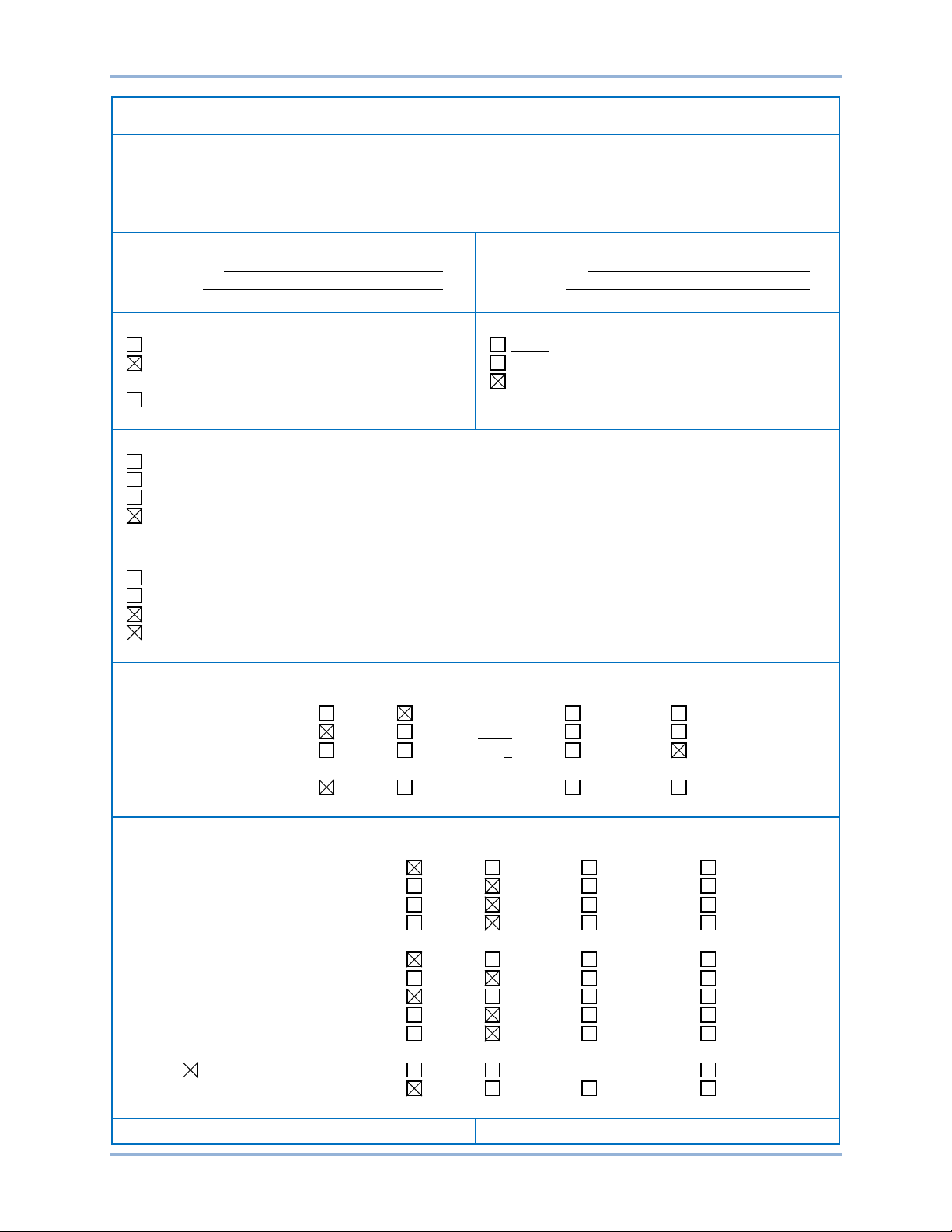
DEVICE PROFILE DOCUMENT
Vendor Name: Basler Electric Company
Device Name: BE1-11
Highest DNP Level Supported:
Level 2.
Device Function:
Master Slave
Notable objects, functions, and/or qualifiers supported in addition to the highest DNP levels supported
- Maximum response time is 150 ms.
Device Profile Document
Table 1 provides a device profile document in the standard format defined in the DNP3 subset definition
document. The table, in combination with the implementation table provided in the Implementation
chapter and the point list tables provided in the Point List chapter, provide a complete application
configuration guide for including the BE1-11 Protection System protocol in any DNP environment.
Table 1. Device Profile Document
(the complete list is described in DNP3 Implementation Table):
- For static (non-change-event) object requests, request qualifier codes 00 and 01 (start-stop), 07
and 08 limited quantity), and 17 and 28 (index) are supported in addition to request qualifier code
06 (no range – or all points).
- Static object requests sent with qualifiers 00,01,06,07, and 08, will be responded to with qualifiers
00 or 01.
- Static object requests sent with qualifiers 17 and 28 will be responded to with qualifiers 17 or 28.
- Only Analog Inputs and Binary Inputs are included in Class 0.
- The user can configure Class 0 by mapping Analog Input points and Binary Input points from
default lists to active “User Mapped Lists” using BESTCOMSPlus®.
- Dead band for each Analog Input point from “User Mapped List” is configurable via object 34, and
class assignment for each reporting binary and analog input point via DNP assign class function.
- Each Analog Input and Analog Output point has configurable scaling factor set through
BESTCOMSPlus.
- Enabling and disabling unsolicited responses on a Class-by-Class basis.
- Device supports DNP over serial (485) port or via Ethernet. Device provides a setting to select the
type of Internet Protocol connection to establish with a master datagram end point or a TCP
listening end point.
- Default variations for objects 1, 2, 30, 32, and 40 are programmable through BESTCOMSPlus or
the devices front panel.
- All DNP settings configured through BESTCOMSPlus or device front panel are saved in non-
volatile memory.
- Dead bands and assigned classes, changed via DNP, can be saved in non-volatile memory on
user request via Analog Output Block object 43 (point named “DNP Save Assigned Class and
Deadband”).
- Binary Outputs fixed list is shown in the Point List chapter.
- Analog Outputs fixed list is shown in the Point List chapter.
- Maximum number of objects allowed in a single control request for Analog Outputs is variable
depending on if a separate object header is used for each selected point or not. The size of SBO
buffer is 600 bytes (maximum 35 Analog Outputs with separate object headers).
- The device does not support putting the control outputs in a local state.
- Binary Input change event buffer size is the number of Binary Inputs multiplied by 4.
- Analog Input change event buffer size is the number of Analog Inputs.
- This device does not support Collision Avoidance.
- Select to Operate time delay is 30 seconds.
- Maximum Time Base Drift over 1 minute is 1.2 ms at room temperature and 3 ms over the entire
operating range.
- Maximum delay measurement error is 50 ms.
- Maximum internal time reference error when set from protocol is 250 ms.
BE1-11 Device Profile Document
Page 10
4 9424200773 Rev A
DEVICE PROFILE DOCUMENT
- IN1-4 is immediately asserted on startup.
Maximum Data Link Frame Size (octets):
Maximum Application Fragment Size (octets):
Maximum Data Link Re-tries:
Maximum Application Layer Re-tries:
Requires Data Link Layer Confirmation:
Requires Application Layer Confirmation:
Timeouts while waiting for:
Sends/Executes Control Operations:
Reports Binary Input Change Events when no
Reports time-tagged Binary Input Change Events
- For Unsolicited Responses, if the number of maximum retries has been reached, the outstation
continues to transmit unsolicited responses with larger intervals (off-line intervals) indefinitely until
confirmation is received from the master.
Transmitted 292
Received 292
None
Fixed at 2 (only if frame sent with confirm
requested)
Configurable
Never
Always
Sometimes
Configurable. Default is NEVER.
Never
Always (not recommended)
When reporting Event Data
When sending multi-fragment responses
Data Link Confirm None Fixed at 3000 ms Variable Configurable
Complete Appl. Fragment None Fixed at _ Variable Configurable
Application Confirm None Fixed at ___ Variable Configurable.
Complete Appl. Response None Fix ed at _ Variable Configurable
Transmitted configurable up to 4096
Received 1024
None
Fixed at
Configurable
5000 ms default
WRITE Binary Outputs Never Always Sometimes Configurable
SELECT/OPERATE Never Always Sometimes Configurable
DIRECT OPERATE Never Always Sometimes Configurable
DIRECT OPERATE - NO ACK Never Always Sometimes Configurable
Count > 1 Never Always Sometimes Configurable
Pulse On Never Always Sometimes Configurable
Pulse Off Never Always Sometimes Configurable
Latch On Never Always Sometimes Configurable
Latch Off Never Always Sometimes Configurable
Queue Never Always Sometimes Configurable
Clear Queue Never Always Sometimes Configurable
Device Profile Document BE1-11
Page 11
9424200773 Rev A 5
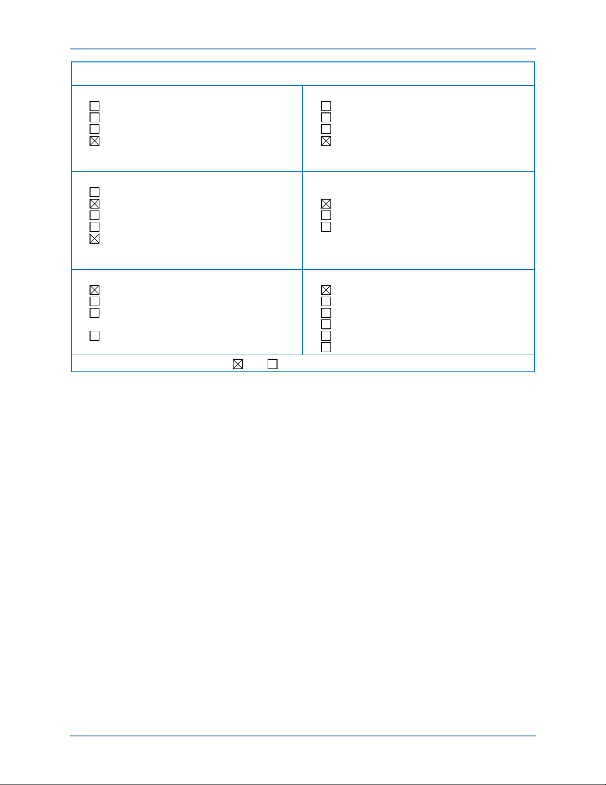
DEVICE PROFILE DOCUMENT
specific variation requested:
when no specific variation requested:
Sends Unsolicited Responses:
Sends Static Data in Unsolicited Responses:
Default Counter Object/Variation:
Counters Roll Over at:
Point- by-point list attached
Sends Multi-Fragment Responses: Yes No
Never
Only time-tagged
Only non-time-tagged
Configurable to send time-tagged or
non-time-tagged (default is time-tagged)
Never
Configurable
Only certain objects
Sometimes (attach explanation)
ENABLE/DISABLE UNSOLICITED
Function codes supported
No Counters Reported
Configurable (attach explanation)
Default Object
Default Variation
Point-by-point list attached
Never
Binary Input Change With Time
Binary Input Change With Relative Time
Configurable
Never
When Device Restarts
When Status Flags Change
No other options are permitted.
No Counters Reported
Configurable (attach explanation)
16 Bits
32 Bits
Other Val ue:
BE1-11 Device Profile Document
Page 12

6 9424200773 Rev A
Device Profile Document BE1-11
Page 13

9424200773 Rev A 7
RESPONSE
with)
Function
(hex)
Qualifier
(hex)
1 0 Binary Inputs –
1 (read)
00,01 (start- stop)
17,28 (index)
1
1
1)
Single-Bit Binary Input
1 (read)
00,01 (start- stop) 06
17,28 (index)
81 (response)
00,01 (start-
1 2 Binary Input with Status
1 (read)
00,01 (start- stop) 06
17,28 (index)
81 (response)
00,01 (start-
2 0 Binary Input Change
request default variation)
1 (read)
06 (no range)
2 1 Binary Input Change
without time
1 (read)
06 (no range)
07,08 (limited qty)
81 (response)
17,28 (index)
2
2
1)
Binary Input Change with
1 (read)
06 (no range)
81 (response)
17,28 (index)
10 0 Binary Output –
1 (read)
00,01 (start- stop)
17,28 (index)
10
2
Binary Output Status
1 (read)
00,01 (start- stop)
17,28 (index)
81
00,01 (start-
12 1 Control Relay Output
3 (select)
6 (dir op Noack)
00,01 (start-stop)
81
echo of
30 0 Analog Input (Variation 0
1 (read)
00,01 (start- stop)
17,28 (index)
81 (response)
00,01 (start-
30 1 32-Bit Analog Input With
1 (read)
00,01 (start- stop)
17,28 (index)
81
00,01 (start-
Implementation Table
Table 2 identifies which object variations, function codes, and qualifiers the BE1-11 DNP supports in both
request messages and in response messages.
For static (non-change-event) objects, requests sent with qualifiers 00, 01, 06, 07, or 08 will be responded
to with qualifiers 00 or 01. Static object requests sent with qualifiers 17 or 28 will be responded to with
qualifiers 17 or 28.
For change-event objects, qualifiers 17 and 28 are always responded.
Table 2. BE1-11 DNP Implementation Table
OBJECT
Obj. Var. Description
(Variation 0 is used to
request default variation)
(default –
see note
(Variation 0 is used to
(default –
see note
time
REQUEST
(BE1-11 will parse)
Function
Codes (dec)
22 (assign class)
22 (assign class)
22 (assign class)
Qualifier Codes
(hex)
06 (no range)
07,08 (limited qty)
(no range)
07,08 (limited qty)
(no range)
07,08 (limited qty)
07,08 (limited qty)
07,08 (limited qty)
(BE1-11 will respond
Codes
Codes
stop)
17,28 (index)
stop)
17,28 (index)
BE1-11 Implementation Table
(default)
(Variation 0 is used to
request default variation)
Block
is used to request default
variation)
Flag
4 (operate)
5 (direct op)
22 (assign class)
22 (assign class)
06 (no range)
07,08 (limited qty)
06 (no range)
07,08 (limited qty)
07,08 (limited qty)
17,28 (index)
06 (no range)
07,08 (limited qty)
06 (no range)
07,08 (limited qty)
stop)
17,28 (index)
request
stop)
17,28 (index)
stop)
17,28 (index)
Page 14

8 9424200773 Rev A
RESPONSE
with)
Function
(hex)
Qualifier
(hex)
30 2 16-Bit Analog Input With
1 (read)
00,01 (start- stop)
17,28 (index)
81
00,01 (start-
30
3
1, 2)
32-Bit Analog Input
1 (read)
00,01 (start- stop)
17,28 (index)
81
00,01 (start-
30 4 16-Bit Analog Input
1 (read)
00,01 (start- stop)
17,28 (index)
81
00,01 (start-
30 5 Short float analog input
1 (read)
00,01 (start- stop)
17,28 (index)
81
00,01 (start-
32 0 Analog Change Event
request default variation)
32
1
1, 2)
32-Bit Analog Input
1 (read)
06 (no range)
81
17,28 (index)
32 2 16-Bit Analog Input
without time
1 (read)
06 (no range)
07,08 (limited qty)
81
17,28
(index)
32 3 32-Bit Analog Input with
time
1 (read)
06 (no range)
07,08 (limited qty)
81
17,28
(index)
32 4 16-Bit Analog Input with
time
1 (read)
06 (no range)
07,08 (limited qty)
81
17,28
(index)
32 5 Short float analog
time
1 (read)
06 (no range)
81
17,28
32 7 Short float analog
change event with time
1 (read)
06 (no range)
07,08 (limited qty)
81
17,28
(index)
34 0 (Variation 0 is used to
1 (read)
00,01 (start17,28 (index)
34 1 16-Bit Analog Input
1 (read)
For read:
00,01,07,08,17,28
81
00,01 (start-
34
2 (default)
32-Bit Analog Input
1 (read)
For read:
00,01,07,08,17,28
81
00,01 (start-
40 0 Analog Output Status –
1
00,01 (start-stop)
17,28 (index)
40
1
32-bit Analog Output
1 (read)
00,01 (start-stop)
17,28 (index)
81
00,01 (start-
OBJECT
Obj. Var. Description
Flag
(default –
see notes
(default –
see notes
Without Flag
Without Flag
(Variation 0 is used to
without time
REQUEST
(BE1-11 will parse)
Function
Codes (dec)
22 (assign class)
22 (assign class)
22 (assign class)
22 (assign class)
Qualifier Codes
(hex)
06 (no range)
07,08 (limited qty)
06 (no range)
07,08 (limited qty)
06 (no range)
07,08 (limited qty)
06 (no range)
07,08 (limited qty)
07,08 (limited qty)
(BE1-11 will respond
Codes
Codes
stop)
17,28 (index)
stop)
17,28 (index)
stop)
17,28 (index)
stop)
17,28 (index)
Implementation Table BE1-11
change event without
request default variation)
Deadband
Deadband
(Variation 0 is used to
request default variation)
Status
2 (write)
2 (write)
07,08 (limited qty)
00,01,06,07,08,17,
28
For write:
00,01,06,07,08,17,
28
For write:
06 (no range)
07,08 (limited qty)
06 (no range)
07,08 (limited qty)
(index)
stop)
stop)
17,28 (index)
stop)
17,28 (index)
stop)
17,28 (index)
Page 15

9424200773 Rev A 9
RESPONSE
with)
Function
(hex)
Qualifier
(hex)
40
2 (default)
16-bit Analog Output
1 (read)
00,01 (start-stop)
17,28 (index)
81
00,01 (start-
40 3 Short float Analog
1 (read)
00,01 (start-stop)
17,28 (index)
81
00,01 (start-
41 1 32-bit Analog Output
2 (select)
6 (dir op noack)
00,01 (start-stop)
81
echo of
41 2 16-bit Analog Output
3 (select)
6 (dir op noack)
00,01 (start-stop)
81
echo of
41 3 Short Float Analog
3 (select)
6 (dir op noack)
00,01 (start-stop)
81
echo of
50 1 Time and Date
1 (read)
00,01 (start-stop)
17,28 (index)
81
00,01 (start-
60 1 Class 0 Data (Note 4)
1 (read)
06 (no range or all)
81
60 2 Class 1 Data
1 (read)
22 (assign class)
06 (no range or all)
81
60 3 Class 2 Data
1 (read)
22 (assign class)
06 (no range or all)
81
60 4 Class 3 Data
1 (read)
22 (assign class)
06 (no range or all)
81
80 1 Internal Indications
2 (write)
00 (start-stop)
(index=7)
110 Octet String
1 (read)
00,01 (start-stop)
17,28 (index)
81
00,01 (start-
No Object(function code
only) (See Note 3)
13 (cold restart)
No Object(function code
only) (See Note 3)
14 (warm
restart)
No Object (function code
only)
23 (delay
measurement)
OBJECT
Obj. Var. Description
Status
Output Status
Block
Block
Output Block
REQUEST
(BE1-11 will parse)
Function
Codes (dec)
3 (operate)
4 (direct op)
4 (operate)
5 (direct op)
4 (operate)
5 (direct op)
Qualifier Codes
(hex)
06 (no range)
07,08 (limited qty)
06 (no range)
07,08 (limited qty)
07,08 (limited qty)
17,28 (index)
07,08 (limited qty)
17,28 (index)
07,08 (limited qty)
17,28 (index)
(BE1-11 will respond
Codes
Codes
stop)
17,28 (index)
stop)
17,28 (index)
request
request
request
2 (write)
20 (enable
unsol)
21 (disable
unsol)
20 (enable
unsol)
21 (disable
unsol)
20 (enable
unsol)
21 (disable
unsol)
06 (no range or all)
07 (limited qty=1)
08 (limited qty)
07,08 (limited
quantity)
07,08 (limited
quantity)
07,08 (limited
quantity)
06 (no range)
07,08 (limited qty)
stop)
17,28 (index)
stop)
17,28 (index)
BE1-11 Implementation Table
Page 16

10 9424200773 Rev A
Notes for Table 2:
1. A default variation refers to the variation responded to when variation 0 is requested and/or in
class 0, 1, 2, or 3 scans.
2. This is a default “default variation”. Objects 1, 2, 30, 32, and 40 have configurable default
variation.
3. A cold restart is implemented as a warm restart – the DNP process is restarted, not BE1-11.
4. In Class 0 are included all binary input points from binary user map and analog inputs from
analog user map.
Implementation Table BE1-11
Page 17

9424200773 Rev A 11
DNP Settings
This chapter describes configuration settings that must be set to enable the BE1-11 to support DNP.
Selection of DNP Protocol
Selection of DNP protocol is predetermined by the BE1-11 style number. BE1-11 Protection Systems that
support the DNP protocol must have a style number with the fifth character being the letter D (via RS-485)
or the sixth character being the number 3/4 (via Ethernet). This can be verified by reading the BE1-11
style number using BESTCOMSPlus® or the front panel interface. Reference the BE1-11 instruction
manual.
Since the BE1-11 has only one set of DNP data change buffers and connection information, only one
DNP master can actively communicate with the BE1-11 at one time as set by the BE1-11 style number.
DNP settings are configurable through BESTCOMSPlus and the front panel. C ert ain se tti ngs can only be
configured through BESTCOMSPlus, such as analo g and binary input points mapping to user-mapped
lists and scaling settings for analog inputs and analog output status points.
Deadbands for analog inputs and class assignments for events are configured only through DNP object
34 and DNP Assign function.
For more information about changing the BE1-11 parameters, refer to the appropriate BE1-11 instruction
manual.
DNP Configuration through BE STCO MS P lus® and the Front Panel
DNP over Ethernet Settings
1. Type of End Point (TCP Listening or UDP Datagram)
2. Local Port Number
- Default (20000) or
- Other (from 20000-65535)
3. Client IP Address
- any IP address (0.0.0.0) or
- specific IP address (string x.y.z.w)
TCP Listening End Point Setting
1. TCP Keep Alive Time (TCP Connection Timeout) in ms
- Range: 10000 to 86400000 ms (default value = 300000 ms (5 minutes))
UDP End Point Settings
1. Destination UDP port for initial unsolicited null response
- Default value is 20000 with range: 1024 to 65535
2. Destination UDP port for other responses
- Selection between:
- Use source port number (value 0) and
- Other port (range: 1024 to 65535)
3. Association timeout in ms
BE1-11 DNP Settings
- Range: 0 to 86400000 ms
Page 18

12 9424200773 Rev A
Link Layer Settings
1. Data Link Address (Device DNP addr es s)
- Range: 0 to 65519 (default address = 1)
2. Data Link Layer Confirmation
- Select between NEVER/SOMETIMES/ALWAYS (default is NEVER. DNP over Ethernet
should always be NEVER.)
Application Layer Settings
1. Application response fragment size
- Range: 240 to 4096 (default size = 2048)
2. Application confirmation timeout
- Range: 1 to 2678400000 ms (default value = 5000 ms)
Time Synchronization Support Setting
Time synchronization is disabled by default (setting value = 0). Time synchronization should always be
disabled for DNP over Ethernet. Range is from 0 to 2678400000 ms. DNP synch time will affect the
device time based on Time Priority Setup. If not selected in Time Priority Setup settings list (DNP Priority
= 0), DNP sync time will not be used to synchronize device time. Clock setup is configurable using
BESTCOMSPlus and the front panel interface.
Unsolicited Response Support Settings
1. Unsolicited support DISABLED/ENABLED
- The DNP Unsolicited Response Function should be “Disabled” for RS-485 applications
since there is no collision avoidance mechanism.
2. Master Data Link Address (DNP Unsolicited Response Destin ati on Addr es s )
- Range: 0 to 65519 (default address = 5)
3. Unsolicited Response Confirmation Timeout in ms
- Range: 0 to 2678400000 ms. When setting = 0, the value is the same as setting for
Application Confirmation Timeout.
4. Number of unsolicited retries
- Range: 0 to 255 (default = 2)
5. Unsolicited off-line interval in ms
- Range: 0 to 2678400000 ms (default = 10000 (10 seconds))
6. Unsolicited response trigger conditions
- Number of Class 1 events (range from 1 to 100)
- Number of Class 2 events (range from 1 to 100)
- Number of Class 3 events (range from 1 to 100)
Objects Default Variations Settings
1. Default variation for Binary Input (Object 1)
- Range: 1 or 2 (default = 1)
2. Default variation for Binary Input Change (Object 2)
- Range: 1 or 2 (default = 2 (with time))
3. Default variation for Analog Input (Object 30)
- Range: 1, 2, 3, 4, or 5 (default = 3 (32-bit without flag))
4. Default variation for Analog Input Change (Object 32)
- Range: 1, 2, 3, 4, 5, or 7 (default = 1 (32-bit without time))
DNP Settings BE1-11
Page 19

9424200773 Rev A 13
5. Analog Output Status (Object 40)
- Range: 1, 2, or 3 (default = 2 (16-bit))
DNP Configuration through BE STCO MS P lus® Only
Mapping of Binary and Analog Input Points
BESTCOMSPlus supports mapping of selected analog input points and binary input points to user map
lists. Only points from user map lists are included in Class 0, and generate events. User mapped listed
are saved in non-volatile memory. By default, all points from binary input points, as listed in the Point List
chapter are mapped to the binary point user map list. In addition, all points from analog input points, as
listed in the Point List chapter are mapped to the analog user map.
In BESTCOMSPlus, navigate to the following:
• Settings Explorer BE1-11 Communications DNP DNP Analog Points Mapping and
• Settings Explorer BE1-11 Communications DNP DNP Binary Points Mapping
Scaling of (Default) Analog Input Points
When an analog point value exceeds the range of the currently active object variation, the reported value
is a maximum amount for that variation and object variation that includes status has Over Range flag set.
The Over Range status can be avoided if the value is scaled with the appropriate scaling factor. Default
value for any point is 1.000. Range is from 1.000 to maximum 1000000000.000.
BE1-11 Protection Systems have a scaling factor per each analog input point and analog output status
point listed in the default tables in the Point List chapter for analog inputs and analog outputs.
In BESTCOMSPlus, navigate to the following:
• Settings Explorer BE1-11 Communications DNP DNP Analog Input Scaling and
• Settings Explorer BE1-11 Communications DNP DNP Analog Output Scaling
BE1-11 DNP over Serial Line
The settings for RS-485 can be set using BESTCOMSPlus or the front panel interface. The RS-485 port
supports baud rates: 1200, 2400, 4800, 9600, 19200, 38400, 57600, and 115200 (default = 19200). Other
RS-485 configurable settings are Stop Bits, Parity, and Data Size.
BE1-11 DNP via Ethernet
DNP can communicate through Ethernet if the IP address of the BE1-11 is configured as described in the
Communications chapter of the BE1-11 instruction manuals.
BE1-11 DNP Settings
Page 20

14 9424200773 Rev A
DNP Settings BE1-11
Page 21

9424200773 Rev A 15
Point Index
Description
Class
Application
0
60FL Target
1
FGIMT
1
24 Block
1
GIT
2
24 Pickup
1
GIT
3
24 Trip 1 GIT
4
24 Target
1
GIT
5
24 Volts Per Hz
1
GIT
6
25 Block
1
FGI
7
25 Status
1
FGI
8
25 VM1 Status
1
FGI
9
27P-1 Block
1
FGIMT
10
27P-1 Pickup
1
FGIMT
Point List
Binary Input Points
Binary Input changes are scanned every quarter of a nominal cycle. Events are pending in the Slave
application buffer until the Master device sends confirmation that response with pending events was
received. Table 3 describes the default list of binary input points.
User can select Binary Input points from the default list in Table 3 and make active (mapped) list of points
as desired. Only all Binary Input points from “Binary User Map” list are included in Class 0, and generate
events. Only mapped points can be read through any “read” request. Mapping is only possible though
BESTCOMSPlus®.
Class assignment for each active binary input point (point mapped to User Binary Map) is configurable via
DNP assign class function.
Device Event buffer for Binary events is 4 times the total number of Binary inputs in default list.
Default variations for objects 1 and 2 are programmable through BESTCOMSPlus or the front panel of the
BE1-11.
Assigned classes, changed via DNP, can be saved in non-volatile memory on user request, via Analog
Output Block, object 41 (point named “DNP Save Assigned Class and Deadband”).
The application type, listed in the Application column, is defined below:
• F = Feeder Protection System
• G = Generator Protection System
• I = Intertie Protection System
• M = Motor Protection System
• T = Transformer Protection System
Table 3. Binary Input Points
Binary Input Points
Static Object Number: 1
Change Event Object Number: 2
Request Function Codes Supported: 1 (read), 22 (assign class)
Static Variation Reported When Variation 0 Requested: 1 (Binary Input Without Status), Configurable
Change Event Variat ion Reported When Variation 0 Requested: 2 (Binary Input Chan ge With Time),
Configurable
BE1-11 Point List
Page 22

16 9424200773 Rev A
Point Index
Description
Class
Application
11
27P-1 Trip
1
FGIMT
12
27P-1 A Target
1
FGIMT
13
27P-1 B Target
1
FGIMT
14
27P-1 C Target
1
FGIMT
15
27P-2 Block
1
FGIMT
16
27P-2 Pickup
1
FGIMT
17
27P-2 Trip
1
FGIMT
18
27P-2 A Target
1
FGIMT
19
27P-2 B Target
1
FGIMT
20
27P-2 C Target
1
FGIMT
21
27P-3 Block
1
FGIMT
22
27P-3 Pickup
1
FGIMT
23
27P-3 Trip
1
FGIMT
24
27P-3 A Target
1
FGIMT
25
27P-3 B Target
1
FGIMT
26
27P-3 C Target
1
FGIMT
27
27P-4 Block
1
FGIMT
28
27P-4 Pickup
1
FGIMT
29
27P-4 Trip
1
FGIMT
30
27P-4 A Target
1
FGIMT
31
27P-4 B Target
1
FGIMT
32
27P-4 C Target
1
FGIMT
33
27P-5 Block
1
FGIT
34
27P-5 Pickup
1
FGIT
35
27P-5 Trip
1
FGIT
36
27P-5 A Target
1
FGIT
37
27P-5 B Target
1
FGIT
38
27P-5 C Target
1
FGIT
39
27X-1 Block
1
FGIT
40
27X-1 Pickup
1
FGIT
41
27X-1 Trip
1
FGIT
42
27X-1 3V0 Target
1
FGIT
43
27X-1 V2 Target
1
FGIT
44
27X-1 AUX Target
1
FGIT
45
27X-1 3RD Target
1
FGIT
46
27X-1 V1 Target
1
FGIT
47
27X-2 Block
1
FGIT
48
27X-2 Pickup
1
FGIT
49
27X-2 Trip
1
FGIT
50
27X-2 3V0 Target
1
FGIT
Point List BE1-11
Page 23

9424200773 Rev A 17
Point Index
Description
Class
Application
51
27X-2 V2 Target
1
FGIT
52
27X-2 AUX Target
1
FGIT
53
27X-2 3RD Target
1
FGIT
54
27X-2 V1 Target
1
FGIT
55
27X-3 Block
1
FGIT
56
27X-3 Pickup
1
FGIT
57
27X-3 Trip
1
FGIT
58
27X-3 3V0 Target
1
FGIT
59
27X-3 V2 Target
1
FGIT
60
27X-3 AUX Target
1
FGIT
61
27X-3 3RD Target
1
FGIT
62
27X-3 V1 Target
1
FGIT
63
27X-4 Block
1
FGIT
64
27X-4 Pickup
1
FGIT
65
27X-4 Trip
1
FGIT
66
27X-4 3V0 Target
1
FGIT
67
27X-4 V2 Target
1
FGIT
68
27X-4 AUX Target
1
FGIT
69
27X-4 3RD Target
1
FGIT
70
27X-4 V1 Target
1
FGIT
71
59P-1 Block
1
FGIMT
72
59P-1 Pickup
1
FGIMT
73
59P-1 Trip
1
FGIMT
74
59P-1 A Target
1
FGIMT
75
59P-1 B Target
1
FGIMT
76
59P-1 C Target
1
FGIMT
77
59P-2 Block
1
FGIMT
78
59P-2 Pickup
1
FGIMT
79
59P-2 Trip
1
FGIMT
80
59P-2 A Target
1
FGIMT
81
59P-2 B Target
1
FGIMT
82
59P-2 C Target
1
FGIMT
83
59P-3 Block
1
FGIT
84
59P-3 Pickup
1
FGIT
85
59P-3 Trip
1
FGIT
86
59P-3 A Target
1
FGIT
87
59P-3 B Target
1
FGIT
88
59P-3 C Target
1
FGIT
89
59P-4 Block
1
FGIT
90
59P-4 Pickup
1
FGIT
BE1-11 Point List
Page 24

18 9424200773 Rev A
Point Index
Description
Class
Application
91
59P-4 Trip
1
FGIT
92
59P-4 A Target
1
FGIT
93
59P-4 B Target
1
FGIT
94
59P-4 C Target
1
FGIT
95
59X-1 Block
1
FGIT
96
59X-1 Pickup
1
FGIMT
97
59X-1 Trip
1
FGIMT
98
59X-1 3V0 Target
1
FGIMT
99
59X-1 V2 Target
1
FGIMT
100
59X-1 AUX Target
1
FGIMT
101
59X-1 3RD Target
1
FGIMT
102
59X-1 V1 Target
1
FGIMT
103
59X-2 Block
1
FGIMT
104
59X-2 Pickup
1
FGIMT
105
59X-2 Trip
1
FGIMT
106
59X-2 3V0 Target
1
FGIMT
107
59X-2 V2 Target
1
FGIMT
108
59X-2 AUX Target
1
FGIMT
109
59X-2 3RD Target
1
FGIMT
110
59X-2 V1 Target
1
FGIMT
111
59X-3 Block
1
FGIT
112
59X-3 Pickup
1
FGIT
113
59X-3 Trip
1
FGIT
114
59X-3 3V0 Target
1
FGIT
115
59X-3 V2 Target
1
FGIT
116
59X-3 AUX Target
1
FGIT
117
59X-3 3RD Target
1
FGIT
118
59X-3 V1 Target
1
FGIT
119
59X-4 Block
1
FGIT
120
59X-4 Pickup
1
FGIT
121
59X-4 Trip
1
FGIT
122
59X-4 3V0 Target
1
FGIT
123
59X-4 V2 Target
1
FGIT
124
59X-4 AUX Target
1
FGIT
125
59X-4 3RD Target
1
FGIT
126
59X-4 V1 Target
1
FGIT
127
50-1 Block
1
FGIMT
128
50-1 Pickup
1
FGIMT
129
50-1 Trip
1
FGIMT
130
50-1 A Target
1
FGIMT
Point List BE1-11
Page 25

9424200773 Rev A 19
Point Index
Description
Class
Application
131
50-1 B Target
1
FGIMT
132
50-1 C Target
1
FGIMT
133
50-1 Negative Sequence Target
1
FGIMT
134
50-1 Residual Target
1
FGIMT
135
50-1 Independent Ground Target
1
FGIMT
136
50-1 67 A Target
1
FGIT
137
50-1 67 B Target
1
FGIT
138
50-1 67 C Target
1
FGIT
139
50-1 67 Negative Sequence Target
1
FGIT
140
50-1 67 Residual Target
1
FGIT
141
50-1 67 Independent Ground Target
1
FGIT
142
50-2 Block
1
FGIMT
143
50-2 Pickup
1
FGIMT
144
50-2 Trip
1
FGIMT
145
50-2 A Target
1
FGIMT
146
50-2 B Target
1
FGIMT
147
50-2 C Target
1
FGIMT
148
50-2 Negative Sequence Target
1
FGIMT
149
50-2 Residual Target
1
FGIMT
150
50-2 Independent Ground Target
1
FGIMT
151
50-2 67 A Target
1
FGIT
152
50-2 67 B Target
1
FGIT
153
50-2 67 C Target
1
FGIT
154
50-2 67 Negative Sequence Target
1
FGIT
155
50-2 67 Residual Target
1
FGIT
156
50-2 67 Independent Ground Target
1
FGIT
157
50-3 Block
1
FGIMT
158
50-3 Pickup
1
FGIMT
159
50-3 Trip
1
FGIMT
160
50-3 A Target
1
FGIMT
161
50-3 B Target
1
FGIMT
162
50-3 C Target
1
FGIMT
163
50-3 Negative Sequence Target
1
FGIMT
164
50-3 Residual Target
1
FGIMT
165
50-3 Independent Ground Target
1
FGIMT
166
50-3 67 A Target
1
FGIT
167
50-3 67 B Target
1
FGIT
168
50-3 67 C Target
1
FGIT
169
50-3 67 Negative Sequence Target
1
FGIT
170
50-3 67 Residual Target
1
FGIT
BE1-11 Point List
Page 26

20 9424200773 Rev A
Point Index
Description
Class
Application
171
50-3 67 Independent Ground Target
1
FGIT
172
50-4 Block
1
FGIMT
173
50-4 Pickup
1
FGIMT
174
50-4 Trip
1
FGIMT
175
50-4 A Target
1
FGIMT
176
50-4 B Target
1
FGIMT
177
50-4 C Target
1
FGIMT
178
50-4 Negative Sequence Target
1
FGIMT
179
50-4 Residual Target
1
FGIMT
180
50-4 Independent Ground Target
1
FGIMT
181
50-4 67 A Target
1
FGIT
182
50-4 67 B Target
1
FGIT
183
50-4 67 C Target
1
FGIT
184
50-4 67 Negative Sequence Target
1
FGIT
185
50-4 67 Residual Target
1
FGIT
186
50-4 67 Independent Ground Target
1
FGIT
187
50-5 Block
1
FGIMT
188
50-5 Pickup
1
FGIMT
189
50-5 Trip
1
FGIMT
190
50-5 A Target
1
FGIMT
191
50-5 B Target
1
FGIMT
192
50-5 C Target
1
FGIMT
193
50-5 Negative Sequence Target
1
FGIMT
194
50-5 Residual Target
1
FGIMT
195
50-5 Independent Ground Target
1
FGIMT
196
50-5 67 A Target
1
FGIT
197
50-5 67 B Target
1
FGIT
198
50-5 67 C Target
1
FGIT
199
50-5 67 Negative Sequence Target
1
FGIT
200
50-5 67 Residual Target
1
FGIT
201
50-5 67 Independent Ground Target
1
FGIT
202
50-6 Block
1
FGIMT
203
50-6 Pickup
1
FGIMT
204
50-6 Trip
1
FGIMT
205
50-6 A Target
1
FGIMT
206
50-6 B Target
1
FGIMT
207
50-6 C Target
1
FGIMT
208
50-6 Negative Sequence Target
1
FGIMT
209
50-6 Residual Target
1
FGIMT
210
50-6 Independent Ground Target
1
FGIMT
Point List BE1-11
Page 27

9424200773 Rev A 21
Point Index
Description
Class
Application
211
50-6 67 A Target
1
FGIT
212
50-6 67 B Target
1
FGIT
213
50-6 67 C Target
1
FGIT
214
50-6 67 Negative Sequence Target
1
FGIT
215
50-6 67 Residual Target
1
FGIT
216
50-6 67 Independent Ground Target
1
FGIT
217
51-1 Block
1
FGITM
218
51-1 Pickup
1
FGITM
219
51-1 Trip
1
FGITM
220
51-1 A Target
1
FGITM
221
51-1 B Target
1
FGITM
222
51-1 C Target
1
FGITM
223
51-1 Negative Sequence Target
1
FGITM
224
51-1 Residual Target
1
FGITM
225
51-1 Independent Ground Target
1
FGITM
226
51-1 67 A Target
1
FGIT
227
51-1 67 B Target
1
FGIT
228
51-1 67 C Target
1
FGIT
229
51-1 67 Negative Sequence Target
1
FGIT
230
51-1 67 Residual Target
1
FGIT
231
51-1 67 Independent Ground Target
1
FGIT
232
51-2 Block
1
FGITM
233
51-2 Pickup
1
FGITM
234
51-2 Trip
1
FGITM
235
51-2 A Target
1
FGITM
236
51-2 B Target
1
FGITM
237
51-2 C Target
1
FGITM
238
51-2 Negative Sequence Target
1
FGITM
239
51-2 Residual Target
1
FGITM
240
51-2 Independent Ground Target
1
FGITM
241
51-2 67 A Target
1
FGIT
242
51-2 67 B Target
1
FGIT
243
51-2 67 C Target
1
FGIT
244
51-2 67 Negative Sequence Target
1
FGIT
245
51-2 67 Residual Target
1
FGIT
246
51-2 67 Independent Ground Target
1
FGIT
247
51-3 Block
1
FGITM
248
51-3 Pickup
1
FGITM
249
51-3 Trip
1
FGITM
250
51-3 A Target
1
FGITM
BE1-11 Point List
Page 28

22 9424200773 Rev A
Point Index
Description
Class
Application
251
51-3 B Target
1
FGITM
252
51-3 C Target
1
FGITM
253
51-3 Negative Sequence Target
1
FGITM
254
51-3 Residual Target
1
FGITM
255
51-3 Independent Ground Target
1
FGITM
256
51-3 67 A Target
1
FGIT
257
51-3 67 B Target
1
FGIT
258
51-3 67 C Target
1
FGIT
259
51-3 67 Negative Sequence Target
1
FGIT
260
51-3 67 Residual Target
1
FGIT
261
51-3 67 Independent Ground Target
1
FGIT
262
51-4 Block
1
FGITM
263
51-4 Pickup
1
FGITM
264
51-4 Trip
1
FGITM
265
51-4 A Target
1
FGITM
266
51-4 B Target
1
FGITM
267
51-4 C Target
1
FGITM
268
51-4 Negative Sequence Target
1
FGITM
269
51-4 Residual Target
1
FGITM
270
51-4 Independent Ground Target
1
FGITM
271
51-4 67 A Target
1
FGIT
272
51-4 67 B Target
1
FGIT
273
51-4 67 C Target
1
FGIT
274
51-4 67 Negative Sequence Target
1
FGIT
275
51-4 67 Residual Target
1
FGIT
276
51-4 67 Independent Ground Target
1
FGIT
277
51-5 Block
1
FGITM
278
51-5 Pickup
1
FGITM
279
51-5 Trip
1
FGITM
280
51-5 A Target
1
FGITM
281
51-5 B Target
1
FGITM
282
51-5 C Target
1
FGITM
283
51-5 Negative Sequence Target
1
FGITM
284
51-5 Residual Target
1
FGITM
285
51-5 Independent Ground Target
1
FGITM
286
51-5 67 A Target
1
FGIT
287
51-5 67 B Target
1
FGIT
288
51-5 67 C Target
1
FGIT
289
51-5 67 Negative Sequence Target
1
FGIT
290
51-5 67 Residual Target
1
FGIT
Point List BE1-11
Page 29

9424200773 Rev A 23
Point Index
Description
Class
Application
291
51-5 67 Independent Ground Target
1
FGIT
292
51-6 Block
1
FGIT
293
51-6 Pickup
1
FGIT
294
51-6 Trip
1
FGIT
295
51-6 A Target
1
FGIT
296
51-6 B Target
1
FGIT
297
51-6 C Target
1
FGIT
298
51-6 Negative Sequence Target
1
FGIT
299
51-6 Residual Target
1
FGIT
300
51-6 Independent Ground Target
1
FGIT
301
51-6 67 A Target
1
FGIT
302
51-6 67 B Target
1
FGIT
303
51-6 67 C Target
1
FGIT
304
51-6 67 Negative Sequence SEQ Target
1
FGIT
305
51-6 67 Residual Target
1
FGIT
306
51-6 67 Independent Ground Target
1
FGIT
307
51-7 Block
1
FGIT
308
51-7 Pickup
1
FGIT
309
51-7 Trip
1
FGIT
310
51-7 A Target
1
FGIT
311
51-7 B Target
1
FGIT
312
51-7 C Target
1
FGIT
313
51-7 Negative Sequence Target
1
FGIT
314
51-7 Residual Target
1
FGIT
315
51-7 Independent Ground Target
1
FGIT
316
51-7 67 A Target
1
FGIT
317
51-7 67 B Target
1
FGIT
318
51-7 67 C Target
1
FGIT
319
51-7 67 Negative Sequence Target
1
FGIT
320
51-7 67 Residua Target
1
FGIT
321
51-7 67 Independent Ground Target
1
FGIT
322
32-1 Block
1
FGIM
323
32-1 Pickup
1
FGIM
324
32-1 Trip
1
FGIM
325
32-1 A Over Target
1
FGIM
326
32-1 B Over Target
1
FGIM
327
32-1 C Over Target
1
FGIM
328
32-1 T Over Target
1
FGIM
329
32-1 A Under Target
1
FGIM
330
32-1 B Under Target
1
FGIM
BE1-11 Point List
Page 30

24 9424200773 Rev A
Point Index
Description
Class
Application
331
32-1 C Under Target
1
FGIM
332
32-1 T Under Target
1
FGIM
333
32-2 Block
1
FGI
334
32-2 Pickup
1
FGI
335
32-2 Trip
1
FGI
336
32-2 A Over Target
1
FGI
337
32-2 B Over Target
1
FGI
338
32-2 C Over Target
1
FGI
339
32-2 T Over Target
1
FGI
340
32-2 A Under Target
1
FGI
341
32-2 B Under Target
1
FGI
342
32-2 C Under Target
1
FGI
343
32-2 T Under Target
1
FGI
344
40Z Block
1
G
345
40Z Pickup
1
G
346
40Z Trip 1 G
347
40Z VC Pickup
1
G
348
40Z VC Trip
1
G
349
40Z Z1 Pickup
1 G 350
40Z Z1 Trip
1
G
351
40Z Z1 Target
1
G
352
40Z Z1 VC Pickup
1 G 353
40Z Z1 VC Trip
1
G
354
40Z Z1 VC Target
1
G
355
40Z Z2 Pickup
1
G
356
40Z Z2 Trip
1
G
357
40Z Z2 Target
1
G
358
40Z Z2 VC Pickup
1 G 359
40Z Z2 VC Trip
1
G
360
40Z Z2 VC Target
1
G
361
40Q Block
1
GM
362
40Q Pickup
1
GM
363
40Q Trip
1
GM
364
40Q Target
1
GM
365
81-1 Block
1
FGIMT
366
81-1 Pickup
1
FGIMT
367
81-1 Trip
1
FGIMT
368
81-1 Over Target
1
FGIMT
369
81-1 Under Target
1
FGIMT
370
81-1 Rate of Change Target
1
FGIMT
Point List BE1-11
Page 31

9424200773 Rev A 25
Point Index
Description
Class
Application
371
81-2 Block
1
FGIMT
372
81-2 Pickup
1
FGIMT
373
81-2 Trip
1
FGIMT
374
81-2 Over Target
1
FGIMT
375
81-2 Under Target
1
FGIMT
376
81-2 Rate of Change Target
1
FGIMT
377
81-3 Block
1
FGIMT
378
81-3 Pickup
1
FGIMT
379
81-3 Trip
1
FGIMT
380
81-3 Over Target
1
FGIMT
381
81-3 Under Target
1
FGIMT
382
81-3 Rate of Change Target
1
FGIMT
383
81-4 Block
1
FGIMT
384
81-4 Pickup
1
FGIMT
385
81-4 Trip
1
FGIMT
386
81-4 Over Target
1
FGIMT
387
81-4 Under Target
1
FGIMT
388
81-4 Rate of Change Target
1
FGIMT
389
81-5 Block
1
FGIT
390
81-5 Pickup
1
FGIT
391
81-5 Trip
1
FGIT
392
81-5 Over Target
1
FGIT
393
81-5 Under Target
1
FGIT
394
81-5 Rate of Change Target
1
FGIT
395
81-6 Block
1
FGIT
396
81-6 Pickup
1
FGIT
397
81-6 Trip
1
FGIT
398
81-6 Over Target
1
FGIT
399
81-6 Under Target
1
FGIT
400
81-6 Rate of Change Target
1
FGIT
401
81-7 Block
1
FGIT
402
81-7 Pickup
1
FGIT
403
81-7 Trip
1
FGIT
404
81-7 Over Target
1
FGIT
405
81-7 Under Target
1
FGIT
406
81-7 Rate of Change Target
1
FGIT
407
81-8 Block
1
FGIT
408
81-8 Pickup
1
FGIT
409
81-8 Trip
1
FGIT
410
81-8 Over Target
1
FGIT
BE1-11 Point List
Page 32

26 9424200773 Rev A
Point Index
Description
Class
Application
411
81-8 Under Target
1
FGIT
412
81-8 Rate of Change Target
1
FGIT
413
43-1 Pulse
1
FGIMT
414
43-1 Reset
1
FGIMT
415
43-1 Set
1
FGIMT
416
43-1 Output
1
FGIMT
417
Reserved
418
43-1 Blocking Tag
1
FGIMT
419
43-1 Informational Tag
1
FGIMT
420
43-1 Blocking Untag
1
FGIMT
421
43-1 Informational Untag
1
FGIMT
422
43-1 Blocking Tag Status
1
FGIMT
423
43-1 Informational Tag Status
1
FGIMT
424
43-2 Pulse
1
FGIMT
425
43-2 Reset
1
FGIMT
426
43-2 Set
1
FGIMT
427
43-2 Output
1
FGIMT
428
Reserved
429
43-2 Blocking Tag
1
FGIMT
430
43-2 Informational Tag
1
FGIMT
431
43-2 Blocking Untag
1
FGIMT
432
43-2 Informational Untag
1
FGIMT
433
43-2 Blocking Tag Status
1
FGIMT
434
43-2 Informational Tag Status
1
FGIMT
435
43-3 Pulse
1
FGIMT
436
43-3 Reset
1
FGIMT
437
43-3 Set
1
FGIMT
438
43-3 Output
1
FGIMT
439
Reserved
440
43-3 Blocking Tag
1
FGIMT
441
43-3 Informational Tag
1
FGIMT
442
43-3 Blocking Untag
1
FGIMT
443
43-3 Informational Untag
1
FGIMT
444
43-3 Blocking Tag Status
1
FGIMT
445
43-3 Informational Tag Status
1
FGIMT
446
43-4 Pulse
1
FGIMT
447
43-4 Reset
1
FGIMT
448
43-4 Set
1
FGIMT
449
43-4 Output
1
FGIMT
450
Reserved
Point List BE1-11
Page 33

9424200773 Rev A 27
Point Index
Description
Class
Application
451
43-4 Blocking Tag
1
FGIMT
452
43-4 Informational Tag
1
FGIMT
453
43-4 Blocking Untag
1
FGIMT
454
43-4 Informational Untag
1
FGIMT
455
43-4 Blocking Tag Status
1
FGIMT
456
43-4 Informational Tag Status
1
FGIMT
457
43-5 Pulse
1
FGIMT
458
43-5 Reset
1
FGIMT
459
43-5 Set
1
FGIMT
460
43-5 Output
1
FGIMT
461
Reserved
462
43-5 Blocking Tag
1
FGIMT
463
43-5 Informational Tag
1
FGIMT
464
43-5 Blocking Untag
1
FGIMT
465
43-5 Informational Untag
1
FGIMT
466
43-5 Blocking Tag Status
1
FGIMT
467
43-5 Informational Tag Status
1
FGIMT
468
86-1 Reset
1
FGIMT
469
86-1 Set
1
FGIMT
470
86-1 Output
1
FGIMT
471
86-2 Reset
1
FGIMT
472
86-2 Set
1
FGIMT
473
86-2 Output
1
FGIMT
474
101 Trip
1
FGIMT
475
101 Close
1
FGIMT
476
101 Trip Out
1
FGIMT
477
101 Close Out
1
FGIMT
478
101 TSC Out
1
FGIMT
479
101 CSC Out
1
FGIMT
480
Reserved
481
101 Blocking Tag
1
FGIMT
482
101 Informational Tag
1
FGIMT
483
101 Blocking Untag
1
FGIMT
484
101 Informational Untag
1
FGIMT
485
101 Blocking Tag Status
1
FGIMT
486
101 Informational Tag Status
1
FGIMT
487
62-1 Block
1
FGIMT
488
62-1 Initiate
1
FGIMT
489
62-1 Target
1
FGIMT
490
62-2 Block
1
FGIMT
BE1-11 Point List
Page 34

28 9424200773 Rev A
Point Index
Description
Class
Application
491
62-2 Initiate
1
FGIMT
492
62-2 Target
1
FGIMT
493
62-3 Block
1
FGIMT
494
62-3 Initiate
1
FGIMT
495
62-3 Target
1
FGIMT
496
62-4 Block
1
FGIMT
497
62-4 Initiate
1
FGIMT
498
62-4 Target
1
FGIMT
499
62-5 Block
1
FGIMT
500
62-5 Initiate
1
FGIMT
501
62-5 Target
1
FGIMT
502
62-6 Block
1
FGIMT
503
62-6 Initiate
1
FGIMT
504
62-6 Target
1
FGIMT
505
62-7 Block
1
FGIMT
506
62-7 Initiate
1
FGIMT
507
62-7 Target
1
FGIMT
508
62-8 Block
1
FGIMT
509
62-8 Initiate
1
FGIMT
510
62-8 Target
1
FGIMT
511
79 Reclosing
1
FI
512
79 Reclosing
1
FI
513
79 Recloser Running
1
FI
514
79 Recloser Reset
1
FI
515
79 Recloser Lockout
1
FI
516
79 Recloser SCB
1
FI
517
79 Shot 1
1
FI
518
79 Shot 2
1
FI
519
79 Shot 3
1
FI
520
79 Shot 4
1
FI
521
79 Reclose Initiate
1
FI
522
79 Wait 1 FI
523
79 Drive to Lockout (DTL)
1
FI
524
79 Zone Pickup
1
FI
525
79 Zone Trip
1
FI
526
50BF Block
1
FGIMT
527
50BF BFI52
1
FGIMT
528
50BF BFI50
1
FGIMT
529
50BF BFRT
1
FGIMT
530
50BF BFT
1
FGIMT
Point List BE1-11
Page 35

9424200773 Rev A 29
Point Index
Description
Class
Application
531
50BF Target
1
FGIMT
532
50BF Breaker Fail
1
FGIMT
533
50BF Current Detected
1
FGIMT
534
52 Status
1
FGIMT
535
52 Trip Coil Monitor
1
FGIMT
536
Breaker Monitor Block
1
FGIMT
537
Demand Meter IG Alarm
1
FGIMT
538
Demand Meter IN Alarm
1
FGIMT
539
Demand Meter IP Alarm
1
FGIMT
540
Demand Meter IQ Alarm
1
FGIMT
541
Demand Meter var Positive Alarm
1
FGIMT
542
Demand Meter var Negative Alarm
1
FGIMT
543
Demand Meter Watt Forward Alarm
1
FGIMT
544
Demand Meter Watt Reverse Alarm
1
FGIMT
545
Demand Meter S Alarm
1
FGIMT
546
Local Contacts Input 1 State
1
FGIMT
547
Local Contacts Input 2 State
1
FGIMT
548
Local Contacts Input 3 State
1
FGIMT
549
Local Contacts Input 4 State
1
FGIMT
550
Local Contacts Contact 52 TCM
1
FGIMT
551
Local Contacts Output 1 State
1
FGIMT
552
Local Contacts Output 2 State
1
FGIMT
553
Local Contacts Output 3 State
1
FGIMT
554
Local Contacts Output 4 State
1
FGIMT
555
Local Contacts Output 5 State
1
FGIMT
556
Local Contacts Alarm Out State
1
FGIMT
557
Local Contacts Output 1 Override Enable
1
FGIMT
558
Local Contacts Output 2 Override Enable
1
FGIMT
559
Local Contacts Output 3 Override Enable
1
FGIMT
560
Local Contacts Output 4 Override Enable
1
FGIMT
561
Local Contacts Output 5 Override Enable
1
FGIMT
562
Local Contacts Alarm Output Override Enable
1
FGIMT
563
System Data - Power Up
1
FGIMT
564
System Data - Forced Trigger
1
FGIMT
565
System Data - Pickup Log i c
1
FGIMT
566
System Data - Trip Logic
1
FGIMT
567
System Data - Logic Trigger
1
FGIMT
568
System Data - Breaker Stat us
1
FGIMT
569
Flash Error Alarm
1
FGIMT
570
Microprocessor Reset Alarm
1
FGIMT
BE1-11 Point List
Page 36

30 9424200773 Rev A
Point Index
Description
Class
Application
571
Calibration Error Alarm
1
FGIMT
572
Calibration Defaults Loade d Alarm
1
FGIMT
573
Defaults Loaded Alarm
1
FGIMT
574
Microprocessor Overload Alarm
1
FGIMT
575
Power Supply Alarm
1
FGIMT
576
Changes Lost Alarm
1
FGIMT
577
Real Time Clock Alarm
1
FGIMT
578
Date/Time Set Alarm
1
FGIMT
579
Firmware Change Alarm
1
FGIMT
580
Frequency Out of Range Alarm
1
FGIMT
581
Ethernet Link Lost Alarm
1
FGIMT
582
USB Communication Alarm
1
FGIMT
583
IRIG Sync Lost Alarm
1
FGIMT
584
Logic Equal None Alarm
1
FGIMT
585
No User Setting Alarm
1
FGIMT
586
NTP Sync Lost Alarm
1
FGIMT
587
DNP Polls Error Alar m
1
FGIMT
588
Setting Change Alarm
1
FGIMT
589
Output Override Alarm
1
FGIMT
590
Analog Alarm
1
FGIMT
591
Microprocessor Reset Alarm
1
FGIMT
592
Breaker Monitor 1 Alarm
1
FGIMT
593
Breaker Monitor 2 Alarm
1
FGIMT
594
Breaker Monitor 3 Alarm
1
FGIMT
595
Fault Report Timeout Alarm
1
FGIMT
596
Programmable Alarm 1
1
FGIMT
597
Programmable Alarm 2
1
FGIMT
598
Programmable Alarm 3
1
FGIMT
599
Programmable Alarm 4
1
FGIMT
600
Programmable Alarm 5
1
FGIMT
601
Programmable Alarm 6
1
FGIMT
602
Programmable Alarm 7
1
FGIMT
603
Programmable Alarm 8
1
FGIMT
604
Major Alarm
1
FGIMT
605
Minor Alarm
1
FGIMT
606
Target Alarm
1
FGIMT
607
Relay Alarm
1
FGIMT
608
Settings Group SGC Active
1
FGIMT
609
Settings Group SGC Logic Override
1
FGIMT
610
Settings Group Settings Group 0
1
FGIMT
Point List BE1-11
Page 37

9424200773 Rev A 31
Point Index
Description
Class
Application
611
Settings Group Settings Group 1
1
FGIMT
612
Settings Group Settings Group 2
1
FGIMT
613
Settings Group Settings Group 3
1
FGIMT
614
50-1 Positive Sequence Target
1
FGIMT
615
50-1 67 Positive Sequence Target
1
FGIT
616
50-2 Positive Sequence Target
1
FGIMT
617
50-2 67 Positive Sequence Target
1
FGIT
618
50-3 Positive Sequence Target
1
FGIMT
619
50-3 67 Positive Sequence Target
1
FGIT
620
50-4 Positive Sequence Target
1
FGIMT
621
50-4 67 Positive Sequence Target
1
FGIT
622
50-5 Positive Sequence Target
1
FGIMT
623
50-5 67 Positive Sequence Target
1
FGIT
624
50-6 Positive Sequence Target
1
FGIMT
625
50-6 67 Positive Sequence Target
1
FGIT
626
51-1 Positive Sequence Target
1
FGIMT
627
51-1 67 Positive Sequence Target
1
FGIT
628
51-2 Positive Sequence Target
1
FGIMT
629
51-2 67 Positive Sequence Target
1
FGIT
630
51-3 Positive Sequence Target
1
FGIMT
631
51-3 67 Positive Sequence Target
1
FGIT
632
51-4 Positive Sequence Target
1
FGIMT
633
51-4 67 Positive Sequence Target
1
FGIT
634
51-5 Positive Sequence Target
1
FGIMT
635
51-5 67 Positive Sequence Target
1
FGIT
636
51-6 Positive Sequence Target
1
FGIT
637
51-6 67 Positive Sequence Target
1
FGIT
638
51-7 Positive Sequence Target
1
FGIT
639
51-7 67 Positive Sequence Target
1
FGIT
640
Programmable Alarm 9
1
FGIMT
641
Programmable Alarm 10
1
FGIMT
642
Programmable Alarm 11
1
FGIMT
643
Programmable Alarm 12
1
FGIMT
644
Programmable Alarm 13
1
FGIMT
645
Programmable Alarm 14
1
FGIMT
646
Programmable Alarm 15
1
FGIMT
647
Programmable Alarm 16
1
FGIMT
648
87N-1 Block
1
GT
649
87N-1 Pickup
1
GT
650
87N-1 Trip
1
GT
BE1-11 Point List
Page 38

32 9424200773 Rev A
Point Index
Description
Class
Application
651
87N-1 Target
1
GT
652
51TF Block
1
T
653
51TF Pickup
1
T
654
51TF Trip
1 T 655
51TF Target
1
T
656
51TF Through Fault
1
T
657
Demand Meter CT Circuit 2 3I0 Alarm
1
FGIMT
658
Demand Meter CT Circuit 2 IP Alarm
1
FGIMT
659
Demand Meter CT Circuit 2 I2 Alarm
1
FGIMT
660
Demand Meter CT Circuit 2 IG Alarm
1
FGIMT
661
Local Contacts Output 6 State
1
FGIMT
662
Local Contacts Output 7 State
1
FGIMT
663
Local Contacts Output 8 State
1
FGIMT
664-666
Reserved
667
Local Contacts Output 6 Override Enable
1
FGIMT
668
Local Contacts Output 7 Override Enable
1
FGIMT
669
Local Contacts Output 8 Override Enable
1
FGIMT
670-672
Reserved
673
Local Contacts Input 5 State
1
FGIMT
674
Local Contacts Input 6 State
1
FGIMT
675
Local Contacts Input 7 State
1
FGIMT
676-685
Reserved
686
Analog Input Protection 1 Block
1
FGIMT
687
Analog Input Protection 1 Pick up
1
FGIMT
688
Analog Input Protection 1 Trip
1
FGIMT
689
Analog Input Protection 1 Target
1
FGIMT
690
Analog Input Protect ion 2 B lock
1
FGIMT
691
Analog Input Protection 2 Pick up
1
FGIMT
692
Analog Input Protection 2 Trip
1
FGIMT
693
Analog Input Protection 2 Target
1
FGIMT
694
Analog Input Protection 3 Block
1
FGIMT
695
Analog Input Protection 3 Pick up
1
FGIMT
696
Analog Input Protection 3 Trip
1
FGIMT
697
Analog Input Protection 3 Target
1
FGIMT
698
Analog Input Protection 4 Block
1
FGIMT
699
Analog Input Protection 4 Pick up
1
FGIMT
700
Analog Input Protection 4 Trip
1
FGIMT
701
Analog Input Protection 4 Target
1
FGIMT
702
Analog Input Protection 5 Block
1
FGIMT
703
Analog Input Protection 5 Pick up
1
FGIMT
Point List BE1-11
Page 39

9424200773 Rev A 33
Point Index
Description
Class
Application
704
Analog Input Protection 5 Trip
1
FGIMT
705
Analog Input Protection 5 Target
1
FGIMT
706
Analog Input Protection 6 Block
1
FGIMT
707
Analog Input Protection 6 Pic k up
1
FGIMT
708
Analog Input Protection 6 Trip
1
FGIMT
709
Analog Input Protection 6 Target
1
FGIMT
710
Analog Input Protection 7 Block
1
FGIMT
711
Analog Input Protection 7 Pick up
1
FGIMT
712
Analog Input Protection 7 Trip
1
FGIMT
713
Analog Input Protection 7 Target
1
FGIMT
714
Analog Input Protection 8 Block
1
FGIMT
715
Analog Input Protection 8 Pick up
1
FGIMT
716
Analog Input Protection 8 Trip
1
FGIMT
717
Analog Input Protection 8 Target
1
FGIMT
718
48 Block 1 M
719
48 Trip 1 M
720
48 Target
1
M
721
66 Block 1 M
722
66 Block Start
1 M 723
Motor Status - Motor is Started
1
M
724
Motor Status - Motor is Stopped
1
M
725
Motor Status - Block
1 M 726
Motor Status - Emergency Start
1
M
727
Motor Status - Lockout
1
M
728
Motor Status - Starting
1
M
729
Motor Status - Running
1
M
730
Motor Status - Stopped
1
M
731
Motor Status - Start Blocked
1 M 732-736
Reserved
737
49RTD-1 Block
1
FGIMT
738
49RTD-1 Pickup
1
FGIMT
739
49RTD-1 Trip
1
FGIMT
740
49RTD-1 RTD 1-1 Target
1
FGIMT
741
49RTD-1 RTD 1-2 Target
1
FGIMT
742
49RTD-1 RTD 1-3 Target
1
FGIMT
743
49RTD-1 RTD 1-4 Target
1
FGIMT
744
49RTD-1 RTD 1-5 Target
1
FGIMT
745
49RTD-1 RTD 1-6 Target
1
FGIMT
746
49RTD-1 RTD 1-7 Target
1
FGIMT
747
49RTD-1 RTD 1-8 Target
1
FGIMT
BE1-11 Point List
Page 40

34 9424200773 Rev A
Point Index
Description
Class
Application
748
49RTD-1 RTD 1-9 Target
1
FGIMT
749
49RTD-1 RTD 1-10 Target
1
FGIMT
750
49RTD-1 RTD 1-11 Target
1
FGIMT
751
49RTD-1 RTD 1-12 Target
1
FGIMT
752
49RTD-1 RTD 2-1 Target
1
FGIMT
753
49RTD-1 RTD 2-2 Target
1
FGIMT
754
49RTD-1 RTD 2-3 Target
1
FGIMT
755
49RTD-1 RTD 2-4 Target
1
FGIMT
756
49RTD-1 RTD 2-5 Target
1
FGIMT
757
49RTD-1 RTD 2-6 Target
1
FGIMT
758
49RTD-1 RTD 2-7 Target
1
FGIMT
759
49RTD-1 RTD 2-8 Target
1
FGIMT
760
49RTD-1 RTD 2-9 Target
1
FGIMT
761
49RTD-1 RTD 2-10 Target
1
FGIMT
762
49RTD-1 RTD 2-11 Target
1
FGIMT
763
49RTD-1 RTD 2-12 Target
1
FGIMT
764
49RTD-2 Block
1
FGIMT
765
49RTD-2 Pickup
1
FGIMT
766
49RTD-2 Trip
1
FGIMT
767
49RTD-2 RTD 1-1 Target
1
FGIMT
768
49RTD-2 RTD 1-2 Target
1
FGIMT
769
49RTD-2 RTD 1-3 Target
1
FGIMT
770
49RTD-2 RTD 1-4 Target
1
FGIMT
771
49RTD-2 RTD 1-5 Target
1
FGIMT
772
49RTD-2 RTD 1-6 Target
1
FGIMT
773
49RTD-2 RTD 1-7 Target
1
FGIMT
774
49RTD-2 RTD 1-8 Target
1
FGIMT
775
49RTD-2 RTD 1-9 Target
1
FGIMT
776
49RTD-2 RTD 1-10 Target
1
FGIMT
777
49RTD-2 RTD 1-11 Target
1
FGIMT
778
49RTD-2 RTD 1-12 Target
1
FGIMT
779
49RTD-2 RTD 2-1 Target
1
FGIMT
780
49RTD-2 RTD 2-2 Target
1
FGIMT
781
49RTD-2 RTD 2-3 Target
1
FGIMT
782
49RTD-2 RTD 2-4 Target
1
FGIMT
783
49RTD-2 RTD 2-5 Target
1
FGIMT
784
49RTD-2 RTD 2-6 Target
1
FGIMT
785
49RTD-2 RTD 2-7 Target
1
FGIMT
786
49RTD-2 RTD 2-8 Target
1
FGIMT
787
49RTD-2 RTD 2-9 Target
1
FGIMT
Point List BE1-11
Page 41

9424200773 Rev A 35
Point Index
Description
Class
Application
788
49RTD-2 RTD 2-10 Target
1
FGIMT
789
49RTD-2 RTD 2-11 Target
1
FGIMT
790
49RTD-2 RTD 2-12 Target
1
FGIMT
791
49RTD-3 Block
1
FGIMT
792
49RTD-3 Pickup
1
FGIMT
793
49RTD-3 Trip
1
FGIMT
794
49RTD-3 RTD 1-1 Target
1
FGIMT
795
49RTD-3 RTD 1-2 Target
1
FGIMT
796
49RTD-3 RTD 1-3 Target
1
FGIMT
797
49RTD-3 RTD 1-4 Target
1
FGIMT
798
49RTD-3 RTD 1-5 Target
1
FGIMT
799
49RTD-3 RTD 1-6 Target
1
FGIMT
800
49RTD-3 RTD 1-7 Target
1
FGIMT
801
49RTD-3 RTD 1-8 Target
1
FGIMT
802
49RTD-3 RTD 1-9 Target
1
FGIMT
803
49RTD-3 RTD 1-10 Target
1
FGIMT
804
49RTD-3 RTD 1-11 Target
1
FGIMT
805
49RTD-3 RTD 1-12 Target
1
FGIMT
806
49RTD-3 RTD 2-1 Target
1
FGIMT
807
49RTD-3 RTD 2-2 Target
1
FGIMT
808
49RTD-3 RTD 2-3 Target
1
FGIMT
809
49RTD-3 RTD 2-4 Target
1
FGIMT
810
49RTD-3 RTD 2-5 Target
1
FGIMT
811
49RTD-3 RTD 2-6 Target
1
FGIMT
812
49RTD-3 RTD 2-7 Target
1
FGIMT
813
49RTD-3 RTD 2-8 Target
1
FGIMT
814
49RTD-3 RTD 2-9 Target
1
FGIMT
815
49RTD-3 RTD 2-10 Target
1
FGIMT
816
49RTD-3 RTD 2-11 Target
1
FGIMT
817
49RTD-3 RTD 2-12 Target
1
FGIMT
818
49RTD-4 Block
1
FGIMT
819
49RTD-4 Pickup
1
FGIMT
820
49RTD-4 Trip
1
FGIMT
821
49RTD-4 RTD 1-1 Target
1
FGIMT
822
49RTD-4 RTD 1-2 Target
1
FGIMT
823
49RTD-4 RTD 1-3 Target
1
FGIMT
824
49RTD-4 RTD 1-4 Target
1
FGIMT
825
49RTD-4 RTD 1-5 Target
1
FGIMT
826
49RTD-4 RTD 1-6 Target
1
FGIMT
827
49RTD-4 RTD 1-7 Target
1
FGIMT
BE1-11 Point List
Page 42

36 9424200773 Rev A
Point Index
Description
Class
Application
828
49RTD-4 RTD 1-8 Target
1
FGIMT
829
49RTD-4 RTD 1-9 Target
1
FGIMT
830
49RTD-4 RTD 1-10 Target
1
FGIMT
831
49RTD-4 RTD 1-11 Target
1
FGIMT
832
49RTD-4 RTD 1-12 Target
1
FGIMT
833
49RTD-4 RTD 2-1 Target
1
FGIMT
834
49RTD-4 RTD 2-2 Target
1
FGIMT
835
49RTD-4 RTD 2-3 Target
1
FGIMT
836
49RTD-4 RTD 2-4 Target
1
FGIMT
837
49RTD-4 RTD 2-5 Target
1
FGIMT
838
49RTD-4 RTD 2-6 Target
1
FGIMT
839
49RTD-4 RTD 2-7 Target
1
FGIMT
840
49RTD-4 RTD 2-8 Target
1
FGIMT
841
49RTD-4 RTD 2-9 Target
1
FGIMT
842
49RTD-4 RTD 2-10 Target
1
FGIMT
843
49RTD-4 RTD 2-11 Target
1
FGIMT
844
49RTD-4 RTD 2-12 Target
1
FGIMT
845
49RTD-5 Block
1
FGIMT
846
49RTD-5 Pickup
1
FGIMT
847
49RTD-5 Trip
1
FGIMT
848
49RTD-5 RTD 1-1 Target
1
FGIMT
849
49RTD-5 RTD 1-2 Target
1
FGIMT
850
49RTD-5 RTD 1-3 Target
1
FGIMT
851
49RTD-5 RTD 1-4 Target
1
FGIMT
852
49RTD-5 RTD 1-5 Target
1
FGIMT
853
49RTD-5 RTD 1-6 Target
1
FGIMT
854
49RTD-5 RTD 1-7 Target
1
FGIMT
855
49RTD-5 RTD 1-8 Target
1
FGIMT
856
49RTD-5 RTD 1-9 Target
1
FGIMT
857
49RTD-5 RTD 1-10 Target
1
FGIMT
858
49RTD-5 RTD 1-11 Target
1
FGIMT
859
49RTD-5 RTD 1-12 Target
1
FGIMT
860
49RTD-5 RTD 2-1 Target
1
FGIMT
861
49RTD-5 RTD 2-2 Target
1
FGIMT
862
49RTD-5 RTD 2-3 Target
1
FGIMT
863
49RTD-5 RTD 2-4 Target
1
FGIMT
864
49RTD-5 RTD 2-5 Target
1
FGIMT
865
49RTD-5 RTD 2-6 Target
1
FGIMT
866
49RTD-5 RTD 2-7 Target
1
FGIMT
867
49RTD-5 RTD 2-8 Target
1
FGIMT
Point List BE1-11
Page 43

9424200773 Rev A 37
Point Index
Description
Class
Application
868
49RTD-5 RTD 2-9 Target
1
FGIMT
869
49RTD-5 RTD 2-10 Target
1
FGIMT
870
49RTD-5 RTD 2-11 Target
1
FGIMT
871
49RTD-5 RTD 2-12 Target
1
FGIMT
872
49RTD-6 Block
1
FGIMT
873
49RTD-6 Pickup
1
FGIMT
874
49RTD-6 Trip
1
FGIMT
875
49RTD-6 RTD 1-1 Target
1
FGIMT
876
49RTD-6 RTD 1-2 Target
1
FGIMT
877
49RTD-6 RTD 1-3 Target
1
FGIMT
878
49RTD-6 RTD 1-4 Target
1
FGIMT
879
49RTD-6 RTD 1-5 Target
1
FGIMT
880
49RTD-6 RTD 1-6 Target
1
FGIMT
881
49RTD-6 RTD 1-7 Target
1
FGIMT
882
49RTD-6 RTD 1-8 Target
1
FGIMT
883
49RTD-6 RTD 1-9 Target
1
FGIMT
884
49RTD-6 RTD 1-10 Target
1
FGIMT
885
49RTD-6 RTD 1-11 Target
1
FGIMT
886
49RTD-6 RTD 1-12 Target
1
FGIMT
887
49RTD-6 RTD 2-1 Target
1
FGIMT
888
49RTD-6 RTD 2-2 Target
1
FGIMT
889
49RTD-6 RTD 2-3 Target
1
FGIMT
890
49RTD-6 RTD 2-4 Target
1
FGIMT
891
49RTD-6 RTD 2-5 Target
1
FGIMT
892
49RTD-6 RTD 2-6 Target
1
FGIMT
893
49RTD-6 RTD 2-7 Target
1
FGIMT
894
49RTD-6 RTD 2-8 Target
1
FGIMT
895
49RTD-6 RTD 2-9 Target
1
FGIMT
896
49RTD-6 RTD 2-10 Target
1
FGIMT
897
49RTD-6 RTD 2-11 Target
1
FGIMT
898
49RTD-6 RTD 2-12 Target
1
FGIMT
899
87 Block
1
GMT
900
87 Pickup
1
GMT
901
87 Trip 1 GMT
902
87 A Target
1
GMT
903
87 B Target
1
GMT
904
87 C Target
1
GMT
905
87 Alarm
1
GMT
906
Logic Label 1
1
FGIMT
907
Logic Label 2
1
FGIMT
BE1-11 Point List
Page 44

38 9424200773 Rev A
Point Index
Description
Class
Application
908
Logic Label 3
1
FGIMT
909
Logic Label 4
1
FGIMT
910
Logic Label 5
1
FGIMT
911
Logic Label 6
1
FGIMT
912
Logic Label 7
1
FGIMT
913
Logic Label 8
1
FGIMT
914
Logic Label 9
1
FGIMT
915
Logic Label 10
1
FGIMT
916
Logic Label 11
1
FGIMT
917
Logic Label 12
1
FGIMT
918
49TC Block
1
M
919
49TC Locked Rotor
1
M
920
49TC Overloaded
1 M 921
49TC Trip
1
M
922
49TC Target
1
M
923
Motor Command - Start Motor
1 M 925
Motor Command - Stop Mo tor
1
M
926
Motor Command - Issue Start Command
1
M
927
Motor Command - Issue Stop Command
1 M 928
Remote Module 1 RTD Out of Range Alarm
1
FGIMT
929
Remote Module 1 Default Calibration Loaded Alarm
1
FGIMT
930
Remote Module 1 Defaults Loaded Al arm
1
FGIMT
932
Remote Module 1 Flash Failure Alarm
1
FGIMT
933
Remote Module 1 RTD Communications Sending Fail Alarm
1
FGIMT
934
Remote Module 1 RTD Communications Receiving Fail Alarm
1
FGIMT
935
Remote Module 2 RTD Out of Range Alarm
1
FGIMT
936
Remote Module 2 Default Calibration Loaded Alarm
1
FGIMT
937
Remote Module 2 Defaults Loaded Al arm
1
FGIMT
938
Remote Module 2 Flash Failure Alarm
1
FGIMT
939
Remote Module 2 RTD Communications Sending Fail Alarm
1
FGIMT
940
Remote Module 2 RTD Communications Receiving Fail Alarm
1
FGIMT
941-1003
Reserved
1004
Alarms Eth Excess Traffic
1
FGIMT
1005
25 Volt Synced
1
FGI
1006
25 Angle Synced
1
FGI
1007
25 Freq Synced
1
FGI
1008
50-1 Unbalance
1
FGIMT
1009
50-1 67 Unbalance
1
FGIT
1010
50-2 Unbalance
1
FGIMT
1011
50-2 67 Unbalance
1
FGIT
Point List BE1-11
Page 45

9424200773 Rev A 39
Point Index
Description
Class
Application
1012
50-3 Unbalance
1
FGIMT
1013
50-3 67 Unbalance
1
FGIT
1014
50-4 Unbalance
1
FGIMT
1015
50-4 67 Unbalance
1
FGIT
1016
50-5 Unbalance
1
FGIMT
1017
50-5 67 Unbalance
1
FGIT
1018
50-6 Unbalance
1
FGIMT
1019
50-6 67 Unbalance
1
FGIT
1020
50-7 Block
1
T
1021
50-7 Pickup
1 T 1022
50-7 Trip 1 T
1023
50-7 A Target
1
T
1024
50-7 B Target
1 T 1025
50-7 C Target
1
T
1026
50-7 Negative Sequence Target
1
T
1027
50-7 Residual Target
1 T 1028
50-7 Independent Ground Target
1
T
1029
50-7 67 A Target
1
T
1030
50-7 67 B Target
1 T 1031
50-7 67 C Target
1
T
1032
50-7 67 Negative Sequence Target
1
T
1033
50-7 67 Residual Target
1 T 1034
50-7 67 Independent Ground Target
1
T
1035
50-7 Positive Sequence Target
1
T
1036
50-7 67 Positive Sequence Target
1
T
1037
50-7 Unbalance
1
T
1038
50-7 67 Unbalance
1
T
1039
50-8 Block
1 T 1040
50-8 Pickup
1
T
1041
50-8 Trip 1 T
1042
50-8 A Target
1 T 1043
50-8 B Target
1
T
1044
50-8 C Target
1
T
1045
50-8 Negative Sequence Target
1 T 1046
50-8 Residual Target
1
T
1047
50-8 Independent Ground Target
1
T
1048
50-8 67 A Target
1 T 1049
50-8 67 B Target
1
T
1050
50-8 67 C Target
1
T
1051
50-8 67 Negative Sequence Target
1
T
BE1-11 Point List
Page 46

40 9424200773 Rev A
Point Index
Description
Class
Application
1052
50-8 67 Residual Target
1 T 1053
50-8 67 Independent Ground Target
1
T
1054
50-8 Positive Sequence Target
1
T
1055
50-8 67 Positive Sequence Target
1 T 1056
50-8 Unbalance
1
T
1057
50-8 67 Unbalance
1
T
1058
50-9 Block
1 T 1059
50-9 Pickup
1
T
1060
50-9 Trip 1 T
1061
50-9 A Target
1 T 1062
50-9 B Target
1
T
1063
50-9 C Target
1
T
1064
50-9 Negative Sequence Target
1 T 1065
50-9 Residual Target
1
T
1066
50-9 Independent Ground Target
1
T
1067
50-9 67 A Target
1 T 1068
50-9 67 B Target
1
T
1069
50-9 67 C Target
1
T
1070
50-9 67 Negative Sequence Target
1 T 1071
50-9 67 Residual Target
1
T
1072
50-9 67 Independent Ground Target
1
T
1073
50-9 Positive Sequence Target
1 T 1074
50-9 67 Positive Sequence Target
1
T
1075
50-9 Unbalance
1
T
1076
50-9 67 Unbalance
1
T
1077
51-1 Unbalance
1
FGIMT
1078
51-1 67 Unbalance
1
FGIT
1079
51-2 Unbalance
1
FGIMT
1080
51-2 67 Unbalance
1
FGIT
1081
51-3 Unbalance
1
FGIMT
1082
51-3 67 Unbalance
1
FGIT
1083
51-4 Unbalance
1
FGIMT
1084
51-4 67 Unbalance
1
FGIT
1085
51-5 Unbalance
1
FGIMT
1086
51-5 67 Unbalance
1
FGIT
1087
51-6 Unbalance
1
FGIT
1088
51-6 67 Unbalance
1
FGIT
1089
51-7 Unbalance
1
FGIT
1090
51-7 67 Unbalance
1
FGIT
1091
51-8 Block
1
T
Point List BE1-11
Page 47

9424200773 Rev A 41
Point Index
Description
Class
Application
1092
51-8 Pickup
1 T 1093
51-8 Trip 1 T
1094
51-8 A Target
1
T
1095
51-8 B Target
1 T 1096
51-8 C Target
1
T
1097
51-8 Negative Sequence Target
1
T
1098
51-8 Residual Target
1 T 1099
51-8 Independent Ground Target
1
T
1100
51-8 67 A Target
1
T
1101
51-8 67 B Target
1 T 1102
51-8 67 C Target
1
T
1103
51-8 67 Negative Sequence Target
1
T
1104
51-8 67 Residual Target
1 T 1105
51-8 67 Independent Ground Target
1
T
1106
51-8 Positive Sequence Target
1
T
1107
51-8 67 Positive Sequence Target
1 T 1108
51-8 Unbalance
1
T
1109
51-8 67 Unbalance
1
T
1110
51-9 Block
1 T 1111
51-9 Pickup
1
T
1112
51-9 Trip 1 T
1113
51-9 A Target
1 T 1114
51-9 B Target
1
T
1115
51-9 C Target
1
T
1116
51-9 Negative Sequence Target
1
T
1117
51-9 Residual Target
1
T
1118
51-9 Independent Ground Target
1
T
1119
51-9 67 A Target
1 T 1120
51-9 67 B Target
1
T
1121
51-9 67 C Target
1
T
1122
51-9 67 Negative Sequence Target
1 T 1123
51-9 67 Residual Target
1
T
1124
51-9 67 Independent Ground Target
1
T
1125
51-9 Positive Sequence Target
1 T 1126
51-9 67 Positive Sequence Target
1
T
1227
51-9 Unbalance
1
T
1128
51-9 67 Unbalance
1 T 1129
87 Unrestrained Trip
1
GMT
1130
87 Transient Monitor
1
GMT
1131
87 Unrestrained A
1
GMT
BE1-11 Point List
Page 48

42 9424200773 Rev A
Point Index
Description
Class
Application
1132
87 Unrestrained B
1
GMT
1133
87 Unrestrained C
1
GMT
1134
87 2nd Harmonic Inhibit
1
GMT
1135
87 5th Harmonic Inhibit
1
GMT
1136
55 Block 1 M
1137
55 Pickup
1
M
1138
55 Trip 1 M
1139
55 Target
1
M
1140
21-1 Block
1
G
1141
21-1 Pickup
1 G 1142
21-1 Trip 1 G
1143
21-1 AB 1 G
1144
21-1 BC 1 G
1145
21-1 CA 1 G
1146
21-2 Block
1
G
1147
21-2 Pickup
1 G 1148
21-2 Trip 1 G
1149
21-2 AB 1 G
1150
21-2 BC 1 G
1151
21-2 CA 1 G
1152
78V Block
1
GI
1153
78V Pickup
1
GI
1154
78V Trip 1 GI
1155
78V 1 GI
1156
78OOS Block
1
G
1157
78OOS Pickup
1
G
1158
78OOS Trip
1
G
1159
78OOS 1 G
1160
78OOS MHO Pickup
1
G
1161
78OOS Blinder A Pickup
1
G
1162
78OOS Blinder B Pickup
1 G 1163
25A Block
1
G
1164
25A Status
1
G
1165
25A Volt Synced
1 G 1166
25A Angle Synced
1
G
1167
25A Freq Synced
1
G
1168
25A Close Breaker
1 G 1169
25A VM1 Status
1
G
1170
25A Initiate
1
G
1171
25A Sync Fail
1
G
Point List BE1-11
Page 49

9424200773 Rev A 43
Point Index
Description
Class
Application
1172
25A Raising Volts
1 G 1173
25A Lowering Volts
1
G
1174
25A Raising Freq
1
G
1175
25A Lowering Freq
1 G 1176
25A Sync in Progress
1
G
1177
Power Loss Alarm
1
FGIMT
1178
Logic Alarms
1
FGIMT
1179
87N-2 Block
1
T
1180
87N-2 Pickup
1
T
1181
87N-2 Trip
1 T 1182
87N-2 Target
1
T
1183
49RTD-7 Block
1
FGIMT
1184
49RTD-7 Pickup
1
FGIMT
1185
49RTD-7 Trip
1
FGIMT
1186
49RTD-7 RTD 1-1 Target
1
FGIMT
1187
49RTD-7 RTD 1-2 Target
1
FGIMT
1188
49RTD-7 RTD 1-3 Target
1
FGIMT
1189
49RTD-7 RTD 1-4 Target
1
FGIMT
1190
49RTD-7 RTD 1-5 Target
1
FGIMT
1191
49RTD-7 RTD 1-6 Target
1
FGIMT
1192
49RTD-7 RTD 1-7 Target
1
FGIMT
1193
49RTD-7 RTD 1-8 Target
1
FGIMT
1194
49RTD-7 RTD 1-9 Target
1
FGIMT
1195
49RTD-7 RTD 1-10 Target
1
FGIMT
1196
49RTD-7 RTD 1-11 Target
1
FGIMT
1197
49RTD-7 RTD 1-12 Target
1
FGIMT
1198
49RTD-7 RTD 2-1 Target
1
FGIMT
1199
49RTD-7 RTD 2-2 Target
1
FGIMT
1200
49RTD-7 RTD 2-3 Target
1
FGIMT
1201
49RTD-7 RTD 2-4 Target
1
FGIMT
1202
49RTD-7 RTD 2-5 Target
1
FGIMT
1203
49RTD-7 RTD 2-6 Target
1
FGIMT
1204
49RTD-7 RTD 2-7 Target
1
FGIMT
1205
49RTD-7 RTD 2-8 Target
1
FGIMT
1206
49RTD-7 RTD 2-9 Target
1
FGIMT
1207
49RTD-7 RTD 2-10 Target
1
FGIMT
1208
49RTD-7 RTD 2-11 Target
1
FGIMT
1209
49RTD-7 RTD 2-12 Target
1
FGIMT
1210
49RTD-8 Block
1
FGIMT
1211
49RTD-8 Pickup
1
FGIMT
BE1-11 Point List
Page 50

44 9424200773 Rev A
Point Index
Description
Class
Application
1212
49RTD-8 Trip
1
FGIMT
1213
49RTD-8 RTD 1-1 Target
1
FGIMT
1214
49RTD-8 RTD 1-2 Target
1
FGIMT
1215
49RTD-8 RTD 1-3 Target
1
FGIMT
1216
49RTD-8 RTD 1-4 Target
1
FGIMT
1217
49RTD-8 RTD 1-5 Target
1
FGIMT
1218
49RTD-8 RTD 1-6 Target
1
FGIMT
1219
49RTD-8 RTD 1-7 Target
1
FGIMT
1220
49RTD-8 RTD 1-8 Target
1
FGIMT
1221
49RTD-8 RTD 1-9 Target
1
FGIMT
1222
49RTD-8 RTD 1-10 Target
1
FGIMT
1223
49RTD-8 RTD 1-11 Target
1
FGIMT
1224
49RTD-8 RTD 1-12 Target
1
FGIMT
1225
49RTD-8 RTD 2-1 Target
1
FGIMT
1226
49RTD-8 RTD 2-2 Target
1
FGIMT
1227
49RTD-8 RTD 2-3 Target
1
FGIMT
1228
49RTD-8 RTD 2-4 Target
1
FGIMT
1229
49RTD-8 RTD 2-5 Target
1
FGIMT
1230
49RTD-8 RTD 2-6 Target
1
FGIMT
1231
49RTD-8 RTD 2-7 Target
1
FGIMT
1232
49RTD-8 RTD 2-8 Target
1
FGIMT
1233
49RTD-8 RTD 2-9 Target
1
FGIMT
1234
49RTD-8 RTD 2-10 Target
1
FGIMT
1235
49RTD-8 RTD 2-11 Target
1
FGIMT
1236
49RTD-8 RTD 2-12 Target
1
FGIMT
1237
49RTD-9 Block
1
FGIMT
1238
49RTD-9 Pickup
1
FGIMT
1239
49RTD-9 Trip
1
FGIMT
1240
49RTD-9 RTD 1-1 Target
1
FGIMT
1241
49RTD-9 RTD 1-2 Target
1
FGIMT
1242
49RTD-9 RTD 1-3 Target
1
FGIMT
1243
49RTD-9 RTD 1-4 Target
1
FGIMT
1244
49RTD-9 RTD 1-5 Target
1
FGIMT
1245
49RTD-9 RTD 1-6 Target
1
FGIMT
1246
49RTD-9 RTD 1-7 Target
1
FGIMT
1247
49RTD-9 RTD 1-8 Target
1
FGIMT
1248
49RTD-9 RTD 1-9 Target
1
FGIMT
1249
49RTD-9 RTD 1-10 Target
1
FGIMT
1250
49RTD-9 RTD 1-11 Target
1
FGIMT
1251
49RTD-9 RTD 1-12 Target
1
FGIMT
Point List BE1-11
Page 51

9424200773 Rev A 45
Point Index
Description
Class
Application
1252
49RTD-9 RTD 2-1 Target
1
FGIMT
1253
49RTD-9 RTD 2-2 Target
1
FGIMT
1254
49RTD-9 RTD 2-3 Target
1
FGIMT
1255
49RTD-9 RTD 2-4 Target
1
FGIMT
1256
49RTD-9 RTD 2-5 Target
1
FGIMT
1257
49RTD-9 RTD 2-6 Target
1
FGIMT
1258
49RTD-9 RTD 2-7 Target
1
FGIMT
1259
49RTD-9 RTD 2-8 Target
1
FGIMT
1260
49RTD-9 RTD 2-9 Target
1
FGIMT
1261
49RTD-9 RTD 2-10 Target
1
FGIMT
1262
49RTD-9 RTD 2-11 Target
1
FGIMT
1263
49RTD-9 RTD 2-12 Target
1
FGIMT
1264
49RTD-10 Block
1
FGIMT
1265
49RTD-10 Pickup
1
FGIMT
1266
49RTD-10 Trip
1
FGIMT
1267
49RTD-10 RTD 1-1 Target
1
FGIMT
1268
49RTD-10 RTD 1-2 Target
1
FGIMT
1269
49RTD-10 RTD 1-3 Target
1
FGIMT
1270
49RTD-10 RTD 1-4 Target
1
FGIMT
1271
49RTD-10 RTD 1-5 Target
1
FGIMT
1272
49RTD-10 RTD 1-6 Target
1
FGIMT
1273
49RTD-10 RTD 1-7 Target
1
FGIMT
1274
49RTD-10 RTD 1-8 Target
1
FGIMT
1275
49RTD-10 RTD 1-9 Target
1
FGIMT
1276
49RTD-10 RTD 1-10 Target
1
FGIMT
1277
49RTD-10 RTD 1-11 Target
1
FGIMT
1278
49RTD-10 RTD 1-12 Target
1
FGIMT
1279
49RTD-10 RTD 2-1 Target
1
FGIMT
1280
49RTD-10 RTD 2-2 Target
1
FGIMT
1281
49RTD-10 RTD 2-3 Target
1
FGIMT
1282
49RTD-10 RTD 2-4 Target
1
FGIMT
1283
49RTD-10 RTD 2-5 Target
1
FGIMT
1284
49RTD-10 RTD 2-6 Target
1
FGIMT
1285
49RTD-10 RTD 2-7 Target
1
FGIMT
1286
49RTD-10 RTD 2-8 Target
1
FGIMT
1287
49RTD-10 RTD 2-9 Target
1
FGIMT
1288
49RTD-10 RTD 2-10 Target
1
FGIMT
1289
49RTD-10 RTD 2-11 Target
1
FGIMT
1290
49RTD-10 RTD 2-12 Target
1
FGIMT
1291
49RTD-11 Block
1
FGIMT
BE1-11 Point List
Page 52

46 9424200773 Rev A
Point Index
Description
Class
Application
1292
49RTD-11 Pickup
1
FGIMT
1293
49RTD-11 Trip
1
FGIMT
1294
49RTD-11 RTD 1-1 Target
1
FGIMT
1295
49RTD-11 RTD 1-2 Target
1
FGIMT
1296
49RTD-11 RTD 1-3 Target
1
FGIMT
1297
49RTD-11 RTD 1-4 Target
1
FGIMT
1298
49RTD-11 RTD 1-5 Target
1
FGIMT
1299
49RTD-11 RTD 1-6 Target
1
FGIMT
1300
49RTD-11 RTD 1-7 Target
1
FGIMT
1301
49RTD-11 RTD 1-8 Target
1
FGIMT
1302
49RTD-11 RTD 1-9 Target
1
FGIMT
1303
49RTD-11 RTD 1-10 Target
1
FGIMT
1304
49RTD-11 RTD 1-11 Target
1
FGIMT
1305
49RTD-11 RTD 1-12 Target
1
FGIMT
1306
49RTD-11 RTD 2-1 Target
1
FGIMT
1307
49RTD-11 RTD 2-2 Target
1
FGIMT
1308
49RTD-11 RTD 2-3 Target
1
FGIMT
1309
49RTD-11 RTD 2-4 Target
1
FGIMT
1310
49RTD-11 RTD 2-5 Target
1
FGIMT
1311
49RTD-11 RTD 2-6 Target
1
FGIMT
1312
49RTD-11 RTD 2-7 Target
1
FGIMT
1313
49RTD-11 RTD 2-8 Target
1
FGIMT
1314
49RTD-11 RTD 2-9 Target
1
FGIMT
1315
49RTD-11 RTD 2-10 Target
1
FGIMT
1316
49RTD-11 RTD 2-11 Target
1
FGIMT
1317
49RTD-11 RTD 2-12 Target
1
FGIMT
1318
49RTD-12 Block
1
FGIMT
1319
49RTD-12 Pickup
1
FGIMT
1320
49RTD-12 Trip
1
FGIMT
1321
49RTD-12 RTD 1-1 Target
1
FGIMT
1322
49RTD-12 RTD 1-2 Target
1
FGIMT
1323
49RTD-12 RTD 1-3 Target
1
FGIMT
1324
49RTD-12 RTD 1-4 Target
1
FGIMT
1325
49RTD-12 RTD 1-5 Target
1
FGIMT
1326
49RTD-12 RTD 1-6 Target
1
FGIMT
1327
49RTD-12 RTD 1-7 Target
1
FGIMT
1328
49RTD-12 RTD 1-8 Target
1
FGIMT
1329
49RTD-12 RTD 1-9 Target
1
FGIMT
1330
49RTD-12 RTD 1-10 Target
1
FGIMT
1331
49RTD-12 RTD 1-11 Target
1
FGIMT
Point List BE1-11
Page 53

9424200773 Rev A 47
Point Index
Description
Class
Application
1332
49RTD-12 RTD 1-12 Target
1
FGIMT
1333
49RTD-12 RTD 2-1 Target
1
FGIMT
1334
49RTD-12 RTD 2-2 Target
1
FGIMT
1335
49RTD-12 RTD 2-3 Target
1
FGIMT
1336
49RTD-12 RTD 2-4 Target
1
FGIMT
1337
49RTD-12 RTD 2-5 Target
1
FGIMT
1338
49RTD-12 RTD 2-6 Target
1
FGIMT
1339
49RTD-12 RTD 2-7 Target
1
FGIMT
1340
49RTD-12 RTD 2-8 Target
1
FGIMT
1341
49RTD-12 RTD 2-9 Target
1
FGIMT
1342
49RTD-12 RTD 2-10 Target
1
FGIMT
1343
49RTD-12 RTD 2-11 Target
1
FGIMT
1344
49RTD-12 RTD 2-12 Target
1
FGIMT
1345
49RTD-13 Block
1
FGIMT
1346
49RTD-13 Pickup
1
FGIMT
1347
49RTD-13 Trip
1
FGIMT
1348
49RTD-13 RTD 1-1 Target
1
FGIMT
1349
49RTD-13 RTD 1-2 Target
1
FGIMT
1350
49RTD-13 RTD 1-3 Target
1
FGIMT
1351
49RTD-13 RTD 1-4 Target
1
FGIMT
1352
49RTD-13 RTD 1-5 Target
1
FGIMT
1353
49RTD-13 RTD 1-6 Target
1
FGIMT
1354
49RTD-13 RTD 1-7 Target
1
FGIMT
1355
49RTD-13 RTD 1-8 Target
1
FGIMT
1356
49RTD-13 RTD 1-9 Target
1
FGIMT
1357
49RTD-13 RTD 1-10 Target
1
FGIMT
1358
49RTD-13 RTD 1-11 Target
1
FGIMT
1359
49RTD-13 RTD 1-12 Target
1
FGIMT
1360
49RTD-13 RTD 2-1 Target
1
FGIMT
1361
49RTD-13 RTD 2-2 Target
1
FGIMT
1362
49RTD-13 RTD 2-3 Target
1
FGIMT
1363
49RTD-13 RTD 2-4 Target
1
FGIMT
1364
49RTD-13 RTD 2-5 Target
1
FGIMT
1365
49RTD-13 RTD 2-6 Target
1
FGIMT
1366
49RTD-13 RTD 2-7 Target
1
FGIMT
1367
49RTD-13 RTD 2-8 Target
1
FGIMT
1368
49RTD-13 RTD 2-9 Target
1
FGIMT
1369
49RTD-13 RTD 2-10 Target
1
FGIMT
1370
49RTD-13 RTD 2-11 Target
1
FGIMT
1371
49RTD-13 RTD 2-12 Target
1
FGIMT
BE1-11 Point List
Page 54

48 9424200773 Rev A
Point Index
Description
Class
Application
1372
49RTD-14 Block
1
FGIMT
1373
49RTD-14 Pickup
1
FGIMT
1374
49RTD-14 Trip
1
FGIMT
1375
49RTD-14 RTD 1-1 Target
1
FGIMT
1376
49RTD-14 RTD 1-2 Target
1
FGIMT
1377
49RTD-14 RTD 1-3 Target
1
FGIMT
1378
49RTD-14 RTD 1-4 Target
1
FGIMT
1379
49RTD-14 RTD 1-5 Target
1
FGIMT
1380
49RTD-14 RTD 1-6 Target
1
FGIMT
1381
49RTD-14 RTD 1-7 Target
1
FGIMT
1382
49RTD-14 RTD 1-8 Target
1
FGIMT
1383
49RTD-14 RTD 1-9 Target
1
FGIMT
1384
49RTD-14 RTD 1-10 Target
1
FGIMT
1385
49RTD-14 RTD 1-11 Target
1
FGIMT
1386
49RTD-14 RTD 1-12 Target
1
FGIMT
1387
49RTD-14 RTD 2-1 Target
1
FGIMT
1388
49RTD-14 RTD 2-2 Target
1
FGIMT
1389
49RTD-14 RTD 2-3 Target
1
FGIMT
1390
49RTD-14 RTD 2-4 Target
1
FGIMT
1391
49RTD-14 RTD 2-5 Target
1
FGIMT
1392
49RTD-14 RTD 2-6 Target
1
FGIMT
1393
49RTD-14 RTD 2-7 Target
1
FGIMT
1394
49RTD-14 RTD 2-8 Target
1
FGIMT
1395
49RTD-14 RTD 2-9 Target
1
FGIMT
1396
49RTD-14 RTD 2-10 Target
1
FGIMT
1397
49RTD-14 RTD 2-11 Target
1
FGIMT
1398
49RTD-14 RTD 2-12 Target
1
FGIMT
Binary Output Status Poi nt s and Cont rol Relay Output Blocks
Table 4 lists both the Binary Output Status Points (Object 10) and the Control Relay Output Blocks
(Object 12). It is important to note that Binary Output Status Points are not included in Class 0.
Point List BE1-11
Page 55

9424200773 Rev A 49
Point Index
Description
Control Operations
Off/Trip
On/Close
0
43-1 Operate
On/Off or Close/Trip
2
1
1
43-1 Operate
Pulse 0 3
2
43-1 Untag Blocking Tag
On or Close
0
2
3
43-1 Untag Informational Tag
On or Close
0
1
4
43-1 Tag Blocking Tag
On or Close
0
2
5
43-1 Tag Informational Tag
On or Close
0
1
6
43-2 Operate
On/Off or Close/Trip
2
1
7
43-2 Operate
Pulse 0 3
8
43-2 Untag Blocking Tag
On or Close
0
2
9
43-2 Untag Informational Tag
On or Close
0
1
10
43-2 Tag Blocking Tag
On or Close
0
2
11
43-2 Tag Informational Tag
On or Close
0
1
12
43-3 Operate
On/Off or Close/Trip
2
1
13
43-3 Operate
Pulse 0 3
14
43-3 Untag Blocking Tag
On or Close
0
2
15
43-3 Untag Informational
On or Close
0
1
16
43-3 Tag Blocking Tag
On or Close
0
2
17
43-3 Tag Informational Tag
On or Close
0
1
18
43-4 Operate
On/Off or Close/Trip
2
1
19
43-4 Operate
Pulse 0 3
20
43-4 Untag Blocking Tag
On or Close
0
2
21
43-4 Untag Informational Tag
On or Close
0
1
22
43-4 Tag Blocking Tag
On or Close
0
2
23
43-4 Tag Informational Tag
On or Close
0
1
24
43-5 Operate
On/Off or Close/Trip
2
1
25
43-5 Operate
Pulse 0 3
26
43-5 Untag Blocking Tag
On or Close
0
2
27
43-5 Untag Informational Tag
On or Close
0
1
28
43-5 Tag Blocking Tag
On or Close
0
2
29
43-5 Tag Informational Tag
On or Close
0
1
30
101 Operate
Close/Trip
1
2
31
101 Untag Blocking Tag
On or Close
0
2
32
101 Untag Informational Tag
On or Close
0
1
33
101 Tag Blocking Tag
On or Close
0
2
Table 4. Binary Output Status Points and Control Relay Output Blocks
Binary Output Status Points:
Object Number: 10
Variations supported: 1, 2
Request Function Codes supported: 1 (read)
Default Variation reported when variation 0 requested: 2 (Binary Output Status)
Control Relay Output Blocks
Object Number: 12
Variations supported: 1
Request Function Codes supported: 3 (select), 4 (operate), 5 (direct operate), 6 (direct operate, noack)
BE1-11 Point List
Page 56

50 9424200773 Rev A
Point Index
Description
Control Operations
Off/Trip
On/Close
34
101 Tag Informational Tag
On or Close
0
1
35
Contact Output 1 Override
On/Off or Close/Trip
0
1
36
Contact Output 1 Override
Pulse 0 2
37
Contact Output 2 Override
On/Off or Close/Trip
0
1
38
Contact Output 2 Override
Pulse 0 2
39
Contact Output 3 Override
On/Off or Close/Trip
0
1
40
Contact Output 3 Override
Pulse 0 2
41
Contact Output 4 Override
On/Off or Close/Trip
0
1
42
Contact Output 4 Override
Pulse 0 2
43
Contact Output 5 Override
On/Off or Close/Trip
0
1
44
Contact Output 5 Override
Pulse 0 2
45
Contact Output A Override
On/Off or Close/Trip
0
1
46
Contact Output A Override
Pulse 0 2
47
Contact Output 6 Override
On/Off or Close/Trip
0
1
48
Contact Output 6 Override
Pulse 0 2
49
Contact Output 7 Override
On/Off or Close/Trip
0
1
50
Contact Output 7 Override
Pulse 0 2
51
Contact Output 8 Override
On/Off or Close/Trip
0
1
52
Contact Output 8 Override
Pulse 0 2
53-58
Reserved
Analog Inputs
The following table lists Analog Inputs (Object 30). It is important to note that 16-bit and 32-bit variations
of Analog Inputs, Analog Output Control Blocks, and Analog Output Statuses are transmitted through
DNP as signed numbers. Even for analog input points that are not valid as negative values, the maximum
positive representation for a 16-bit variation is <2
positive representation is <2
31
-1> = 2,147,483,647.
Each Analog Input point has a separate setting for scaling factor. See the appropriate BE1-11 instruction
manual for more information on using BESTCOMSPlus to change scaling factors.
An analog change event will be generated if the point changes its value by the absolute amount equal or
greater than the Dead band. Dead band for each analog point is configurable via object 34. Analog
change events, once generated, will be reported in one of the class polls (1, 2, or 3).
Change events for analog inputs are reported in CURRENT mode (when a change is detected, the report
of the change contains the current value of the time of the report, not the time the change was detected.
Analog input Deadband (Object 34) defines ranges where no action should be taken. Note that active
DNP object 34 point list always matches active Analog Inputs (User Mapped) list.
The user can select analog points from the default analog point list (Table 5) and map them to the active
analog user map list. This mapping is only configurable through BESTCOMSPlus. Only points from the
analog user map list are members of class 0 and reported as events through assigned class.
Note: Table 5 is the default point list for Analog Input Deadband Object: 34.
15
-1> = 32,767. For a 32-bit variation the maximum
Point List BE1-11
Page 57

9424200773 Rev A 51
Point
Index
Change Event Default
Assigned Class
0
Phase Bus Meter Circuit 1 VA Primary Magnitude
2
1
Phase Bus Meter Circuit 1 VA Angle
2
2
Phase Bus Meter Circuit 1 VB Primary Magnitude
2
3
Phase Bus Meter Circuit 1 VB Angle
2
4
Phase Bus Meter Circuit 1 VC Primary Magnitude
2
5
Phase Bus Meter Circuit 1 VC Angle
2
6
Phase Bus Meter Circuit 1 VAB Primary Magnitude
2
7
Phase Bus Meter Circuit 1 VAB Angle
2
8
Phase Bus Meter Circuit 1 VBC Primary Magnitude
2
9
Phase Bus Meter Circuit 1 VBC Angle
2
10
Phase Bus Meter Circuit 1 VCA Primary Magnitude
2
11
Phase Bus Meter Circuit 1 VCA Angle
2
12-13
Reserved
14
Phase Bus Meter Circuit 1 IA Primary Magnitude
2
15
Phase Bus Meter Circuit 1 IA Angle
2
16
Phase Bus Meter Circuit 1 IB Primary Magnitude
2
17
Phase Bus Meter Circuit 1 IB Angle
2
18
Phase Bus Meter Circuit 1 IC Primary Magnitude
2
19
Phase Bus Meter Circuit 1 IC Angle
2
20
Phase Bus Meter Circuit 1 V1 Primary Magnitude
2
21
Phase Bus Meter Circuit 1 V1 Angle
2
22
Phase Bus Meter Circuit 1 V2 Primary Magnitude
2
23
Phase Bus Meter Circuit 1 V2 Angle
2
24
Phase Bus Meter Circuit 1 3V0 Primary Magnitude
2
25
Phase Bus Meter Circuit 1 3V0 Angle
2
26
Phase Bus Meter Circuit 1 I1 Primary Magnitude
2
27
Phase Bus Meter Circuit 1 I1 Angle
2
28
Phase Bus Meter Circuit 1 I2 Primary Magnitude
2
29
Phase Bus Meter Circuit 1 I2 Angle
2
30
Phase Bus Meter Circuit 1 3I0 Primary Magnitude
2
Table 5. Analog Inputs
Analog Inputs
Static Object Number: 30
Change Event Object Number: 32
Request Function Codes Supported: 1 (read), 22 (assign class)
Static Variation Reported When Variation 0 Requested: User programmable. Default “variation 0” is 3
(32-bit Analog Input without Flag).
Change Event Variation Report ed When Var i ati on 0 Reques t ed: User pr ogrammable. Default
“variation”) is 1 (32-bit Analog Change Event without Time).
Analog Input Deadband Object: 34
Description
BE1-11 Point List
Page 58

52 9424200773 Rev A
Point
Index
Change Event Default
Assigned Class
31
Phase Bus Meter Circuit 1 3I0 Angle
2
32
Phase Bus Meter Circuit 1 Watt A Average
2
33
Phase Bus Meter Circuit 1 Watt B Average
2
34
Phase Bus Meter Circuit 1 Watt C Average
2
35
Phase Bus Meter Circuit 1 var A Average
2
36
Phase Bus Meter Circuit 1 var B Average
2
37
Phase Bus Meter Circuit 1 var C Average
2
38
Phase Bus Meter Circuit 1 Frequency
2
39
Phase Bus Meter Circuit 1 VA A
2
40
Phase Bus Meter Circuit 1 VA B
2
41
Phase Bus Meter Circuit 1 VA C
2
42
Phase Bus Meter Circuit 1 PF A
2
43
Phase Bus Meter Circuit 1 PF B
2
44
Phase Bus Meter Circuit 1 PF C
2
45
Phase Bus Meter Circuit 1 Total Watts
2
46
Phase Bus Meter Circuit 1 Total vars
2
47
Phase Bus Meter Circuit 1 Total VA
2
48
Phase Bus Meter Circuit 1 Total PF
2
49
Phase Bus Meter Circuit 1 Positive Watthour A
2
50
Phase Bus Meter Circuit 1 Positive Watthour B
2
51
Phase Bus Meter Circuit 1 Positive Watthour C
2
52
Phase Bus Meter Circuit 1 Positive Watthour Total
2
53
Phase Bus Meter Circuit 1 Positive varhour A
2
54
Phase Bus Meter Circuit 1 Positive varhour B
2
55
Phase Bus Meter Circuit 1 Positive varhour C
2
56
Phase Bus Meter Circuit 1 Positive varhour Total
2
57
Phase Bus Meter Circuit 1 Negative Watthour A
2
58
Phase Bus Meter Circuit 1 Negative Watthour B
2
59
Phase Bus Meter Circuit 1 Negative Watthour C
2
60
Phase Bus Meter Circuit 1 Negative Watthour Total
2
61
Phase Bus Meter Circuit 1 Negative varhour A
2
62
Phase Bus Meter Circuit 1 Negative varhour B
2
63
Phase Bus Meter Circuit 1 Negative varhour C
2
64
Phase Bus Meter Circuit 1 Negative varhour Total
2
65
Aux Bus Meter VA Primary Magnitude
2
66
Aux Bus Meter VA Angle
2
67
Aux Bus Meter VA-3rd Primary Magnitude
2
68
Aux Bus Meter VA-3rd Ang l e
2
69
Aux Bus Meter Frequency
2
Description
Point List BE1-11
Page 59

9424200773 Rev A 53
Point
Index
Change Event Default
Assigned Class
70
Ground Current Meter Fundamental Primary
2
71
Ground Current Meter Fundamental Angle
2
72
Sync Metering Bus1-Bus2 Ang le
2
73
Sync Metering Bus1-Bus 2 F requency
2
74
Sync Metering Bus1-Bu s 2 Vol ts
2
75
Demand Meter IA Present
2
76
Demand Meter IB Present
2
77
Demand Meter IC Present
2
78
Demand Meter IG Present
2
79
Demand Meter 3I0 Present
2
80
Demand Meter I2 Present
2
81
Demand Meter Watts A Present
2
82
Demand Meter Watts B Present
2
83
Demand Meter Watts C Present
2
84
Demand Meter Watts Total Present
2
85
Demand Meter vars A Present
2
86
Demand Meter vars B Present
2
87
Demand Meter vars C Present
2
88
Demand Meter vars Total Present
2
89
Demand Meter VA A Present
2
90
Demand Meter VA B Present
2
91
Demand Meter VA C Present
2
92
Demand Meter VA Total Present
2
93
Demand Meter IA Peak
2
94
Demand Meter IB Peak
2
95
Demand Meter IC Peak
2
96
Demand Meter IG Peak
2
97
Demand Meter 3I0 Peak
2
98
Demand Meter I2 Peak
2
99
Demand Meter Watts A Peak
2
100
Demand Meter Watts B Peak
2
101
Demand Meter Watts C Peak
2
102
Demand Meter Watts Total Peak
2
103
Demand Meter vars A Peak
2
104
Demand Meter vars B Peak
2
105
Demand Meter vars C Peak
2
106
Demand Meter vars Total Peak
2
107
Demand Meter VA A Peak
2
108
Demand Meter VA B Peak
2
Description
BE1-11 Point List
Page 60

54 9424200773 Rev A
Point
Index
Change Event Default
Assigned Class
109
Demand Meter VA C Peak
2
110
Demand Meter VA Total Peak
2
111
Demand Meter Negative Watts A Peak
2
112
Demand Meter Negative Watts B Peak
2
113
Demand Meter Negative Watts C Peak
2
114
Demand Meter Negative Watts Tota l Peak
2
115
Demand Meter Negative vars A Peak
2
116
Demand Meter Negative vars B Peak
2
117
Demand Meter Negative vars C Peak
2
118
Demand Meter Negative vars Total Peak
2
119
Power Quality Frequency 10 seconds
3
120
Power Quality VA Primary 200 milliseconds
3
121
Power Quality VB Primary 200 milliseconds
3
122
Power Quality VC Primary 200 milliseconds
3
123
Power Quality VA Primary 3 seconds
3
124
Power Quality VB Primary 3 seconds
3
125
Power Quality VC Primary 3 seconds
3
126
Power Quality VA Primary 10 minutes
3
127
Power Quality VB Primary 10 minutes
3
128
Power Quality VC Primary 10 minutes
3
129
Power Quality VA Primary 2 hours
3
130
Power Quality VB Primary 2 hours
3
131
Power Quality VC Primary 2 hours
3
132
Power Quality VAB Primary 200 milliseconds
3
133
Power Quality VBC Primary 200 milliseconds
3
134
Power Quality VCA Primary 200 milliseconds
3
135
Power Quality VAB Primary 3 seconds
3
136
Power Quality VBC Primary 3 seconds
3
137
Power Quality VCA Primary 3 seconds
3
138
Power Quality VAB Primary 10 minutes
3
139
Power Quality VBC Primary 10 minutes
3
140
Power Quality VCA Primary 10 minutes
3
141
Power Quality VAB Primary 2 hours
3
142
Power Quality VBC Primary 2 hours
3
143
Power Quality VCA Primary 2 hours
3
144
Power Quality Dip Status
3
145
Power Quality Primary Residual Voltage
3
146
Power Quality Swell Status
3
147
Power Quality Swell Voltage Primary
3
Description
Point List BE1-11
Page 61

9424200773 Rev A 55
Point
Index
Change Event Default
Assigned Class
148
Power Quality U0 200 milliseconds
3
149
Power Quality U2 200 milliseconds
3
150
Power Quality U0 3 seconds
3
151
Power Quality U2 3 seconds
3
152
Power Quality U0 10 minutes
3
153
Power Quality U2 10 minutes
3
154
Power Quality U0 2 hours
3
155
Power Quality U2 2 hours
3
156
Power Quality VA Harmonic 1
3
157
Power Quality VA Harmonic 2
3
158
Power Quality VA Harmonic 3
3
159
Power Quality VA Harmonic 4
3
160
Power Quality VA Harmonic 5
3
161
Power Quality VA Harmonic 6
3
162
Power Quality VA Harmonic 7
3
163
Power Quality VA Harmonic 8
3
164
Power Quality VA Harmonic 9
3
165
Power Quality VA Harmonic 10
3
166
Power Quality VA Harmonic 11
3
167
Power Quality VA Harmonic 12
3
168
Power Quality VA Harmonic 13
3
169
Power Quality VA Harmonic 14
3
170
Power Quality VA Harmonic 15
3
171
Power Quality VB Harmonic 1
3
172
Power Quality VB Harmonic 2
3
173
Power Quality VB Harmonic 3
3
174
Power Quality VB Harmonic 4
3
175
Power Quality VB Harmonic 5
3
176
Power Quality VB Harmonic 6
3
177
Power Quality VB Harmonic 7
3
178
Power Quality VB Harmonic 8
3
179
Power Quality VB Harmonic 9
3
180
Power Quality VB Harmonic 10
3
181
Power Quality VB Harmonic 11
3
182
Power Quality VB Harmonic 12
3
183
Power Quality VB Harmonic 13
3
184
Power Quality VB Harmonic 14
3
185
Power Quality VB Harmonic 15
3
186
Power Quality VC Harmonic 1
3
Description
BE1-11 Point List
Page 62

56 9424200773 Rev A
Point
Index
Change Event Default
Assigned Class
187
Power Quality VC Harmonic 2
3
188
Power Quality VC Harmonic 3
3
189
Power Quality VC Harmonic 4
3
190
Power Quality VC Harmonic 5
3
191
Power Quality VC Harmonic 6
3
192
Power Quality VC Harmonic 7
3
193
Power Quality VC Harmonic 8
3
194
Power Quality VC Harmonic 9
3
195
Power Quality VC Harmonic 10
3
196
Power Quality VC Harmonic 11
3
197
Power Quality VC Harmonic 12
3
198
Power Quality VC Harmonic 13
3
199
Power Quality VC Harmonic 14
3
200
Power Quality VC Harmonic 15
3
201
Power Quality IA Harmonic 1
3
202
Power Quality IA Harmonic 2
3
203
Power Quality IA Harmonic 3
3
204
Power Quality IA Harmonic 4
3
205
Power Quality IA Harmonic 5
3
206
Power Quality IA Harmonic 6
3
207
Power Quality IA Harmonic 7
3
208
Power Quality IA Harmonic 8
3
209
Power Quality IA Harmonic 9
3
210
Power Quality IA Harmonic 10
3
211
Power Quality IA Harmonic 11
3
212
Power Quality IA Harmonic 12
3
213
Power Quality IA Harmonic 13
3
214
Power Quality IA Harmonic 14
3
215
Power Quality IA Harmonic 15
3
216
Power Quality IB Harmonic 1
3
217
Power Quality IB Harmonic 2
3
218
Power Quality IB Harmonic 3
3
219
Power Quality IB Harmonic 4
3
220
Power Quality IB Harmonic 5
3
221
Power Quality IB Harmonic 6
3
222
Power Quality IB Harmonic 7
3
223
Power Quality IB Harmonic 8
3
224
Power Quality IB Harmonic 9
3
225
Power Quality IB Harmonic 10
3
Description
Point List BE1-11
Page 63

9424200773 Rev A 57
Point
Index
Change Event Default
Assigned Class
226
Power Quality IB Harmonic 11
3
227
Power Quality IB Harmonic 12
3
228
Power Quality IB Harmonic 13
3
229
Power Quality IB Harmonic 14
3
230
Power Quality IB Harmonic 15
3
231
Power Quality IC Harmonic 1
3
232
Power Quality IC Harmonic 2
3
233
Power Quality IC Harmonic 3
3
234
Power Quality IC Harmonic 4
3
235
Power Quality IC Harmonic 5
3
236
Power Quality IC Harmonic 6
3
237
Power Quality IC Harmonic 7
3
238
Power Quality IC Harmonic 8
3
239
Power Quality IC Harmonic 9
3
240
Power Quality IC Harmonic 10
3
241
Power Quality IC Harmonic 11
3
242
Power Quality IC Harmonic 12
3
243
Power Quality IC Harmonic 13
3
244
Power Quality IC Harmonic 14
3
245
Power Quality IC Harmonic 15
3
246
Power Quality IG Harmonic 1
3
247
Power Quality IG Harmonic 2
3
248
Power Quality IG Harmonic 3
3
249
Power Quality IG Harmonic 4
3
250
Power Quality IG Harmonic 5
3
251
Power Quality IG Harmonic 6
3
252
Power Quality IG Harmonic 7
3
253
Power Quality IG Harmonic 8
3
254
Power Quality IG Harmonic 9
3
255
Power Quality IG Harmonic 10
3
256
Power Quality IG Harmonic 11
3
257
Power Quality IG Harmonic 12
3
258
Power Quality IG Harmonic 13
3
259
Power Quality IG Harmonic 14
3
260
Power Quality IG Harmonic 15
3
261
Energy Meter Positive Watthour A
2
262
Energy Meter Positive Watthour B
2
263
Energy Meter Positive Watthour C
2
264
Energy Meter Positive Watthour Total
2
Description
BE1-11 Point List
Page 64

58 9424200773 Rev A
Point
Index
Change Event Default
Assigned Class
265
Energy Meter Positive varhour A
2
266
Energy Meter Positive varhour B
2
267
Energy Meter Positive varhour C
2
268
Energy Meter Positive varhour Total
2
269
Energy Meter Negative Watthour A
2
270
Energy Meter Negative Watthour B
2
271
Energy Meter Negative Watthour C
2
272
Energy Meter Negative Watthour Total
2
273
Energy Meter Negative varhour A
2
274
Energy Meter Negative varhour B
2
275
Energy Meter Negative varhour C
2
276
Energy Meter Negative varhour Total
2
277
Fault Report Read-Latest Fault ID
1
278
Fault Report Record-Number
1
279
Fault Report Fault-Re por t Relay Addr es s DNP
1
280
Fault Report Time Stamp-Year
1
281
Fault Report Time Stamp-Month
1
282
Fault Report Time Stamp-Day of Month
1
283
Fault Report Time Stamp-Hour
1
284
Fault Report Time Stamp-Minute
1
285
Fault Report Time Stamp-Second
1
286
Fault Report Time Stamp-Millisecond
1
287
Fault Report Clear-Time
1
288
Fault Report Operate-Time
1
289
Fault Report Trigger-Status BLK0
1
290
Fault Report Trigger-Status BLK1
1
291
Fault Report Trigger-Status BLK2
1
292
Fault Report Trigger-Status BLK3
1
293
Fault Report Trigger-Status BLK4
1
294
Fault Report Trigger-Status BLK5
1
295
Fault Report Trigger-Status BLK6
1
296
Fault Report Trigger-Status BLK7
1
297
Fault Report Trigger-Status BLK8
1
298
Fault Report Trigger-Status BLK9
1
299
Fault Report Trigger-Status BLK10
1
300
Fault Report Trigger-Status BLK11
1
301
Fault Report Trigger-Status BLK12
1
302
Fault Report Trigger-Status BLK13
1
303
Fault Report Trigger-Status BLK14
1
Description
Point List BE1-11
Page 65

9424200773 Rev A 59
Point
Index
Change Event Default
Assigned Class
304
Fault Report Trigger-Status BLK15
1
305
Fault Report Trigger-Status BLK16
1
306
Fault Report Trigger-Status BLK17
1
307
Fault Report Trigger-Status BLK18
1
308
Fault Report Trigger-Status BLK19
1
309
Fault Report Trigger-Status BLK20
1
310
Fault Report Trigger-Status BLK21
1
311
Fault Report Trigger-Status BLK22
1
312
Fault Report Trigger-Status BLK23
1
313
Fault Report Trigger-Status BLK24
1
314
Fault Report Trigger-Status BLK25
1
315
Fault Report Trigger-Status BLK26
1
316
Fault Report Trigger-Status BLK27
1
317
Fault Report Trigger-Status BLK28
1
318
Fault Report Trigger-Status BLK29
1
319
Fault Report Trigger-Status BLK30
1
320
Fault Report Trigger-Status BLK31
1
321
Fault Report Trigger-Status BLK32
1
322
Fault Report Trigger-Status BLK33
1
323
Fault Report Trigger-Status BLK34
1
324
Fault Report Trigger-Status BLK35
1
325
Fault Report Trigger-Status BLK36
1
326
Fault Report Trigger-Status BLK37
1
327
Fault Report Trigger-Status BLK38
1
328
Fault Report Trigger-Status BLK39
1
329
Fault Report Trigger-Status BLK40
1
330
Fault Report Trigger-Status BLK41
1
331
Fault Report Trigger-Status BLK42
1
332
Fault Report Trigger-Status BLK43
1
333
Fault Report Trigger-Status BLK44
1
334
Fault Report Trigger-Status BLK45
1
335
Fault Report Trigger-Status BLK46
1
336
Fault Report Trigger-Status BLK47
1
337
Fault Report Trigger-Status BLK48
1
338
Fault Report Trigger-Status BLK49
1
339
Fault Report Trigger-Status BLK50
1
340
Fault Report Trigger-Status BLK51
1
341
Fault Report Trigger-Status BLK52
1
342
Fault Report Trigger-Status BLK53
1
Description
BE1-11 Point List
Page 66

60 9424200773 Rev A
Point
Index
Change Event Default
Assigned Class
343
Fault Report Trigger-Status BLK54
1
344
Fault Report Trigger-Status BLK55
1
345
Fault Report Trigger-Status BLK56
1
346
Fault Report Trigger-Status BLK57
1
347
Fault Report Trigger-Status BLK58
1
348
Fault Report Trigger-Status BLK59
1
349
Fault Report Trigger-Status BLK60
1
350
Fault Report Trigger-Status BLK61
1
351
Fault Report Trigger-Status BLK62
1
352
Fault Report Trigger-Status BLK63
1
353
Fault Report Trigger-Status BLK64
1
354
Fault Report Trigger-Status BLK65
1
355
Fault Report Trigger-Status BLK66
1
356
Fault Report Trigger-Status BLK67
1
357
Fault Report Trigger-Status BLK68
1
358
Fault Report Trigger-Status BLK69
1
359
Fault Report Trigger-Status BLK70
1
360
Fault Report Trigger-Status BLK71
1
361
Fault Report Trigger-Status BLK72
1
362
Fault Report Trigger-Status BLK73
1
363
Fault Report Trigger-Status BLK74
1
364
Fault Report Trigger-Status BLK75
1
365
Fault Report Trigger-Status BLK76
1
366
Fault Report Trigger-Status BLK77
1
367
Fault Report Trigger-Status BLK78
1
368
Fault Report Trigger-Status BLK79
1
369
Fault Report Trigger-Status BLK80
1
370
Fault Report Trigger-Status BLK81
1
371
Fault Report Trigger-Status BLK82
1
372
Fault Report Event Type
1
373
Fault Report Active-Setting Group
1
374
Fault Report Target-State BLK0
1
375
Fault Report Target-State BLK1
1
376
Fault Report Target-State BLK2
1
377
Fault Report Target-State BLK3
1
378
Fault Report Target-State BLK4
1
379
Fault Report Target-State BLK5
1
380
Fault Report Target-State BLK6
1
381
Fault Report Target-State BLK7
1
Description
Point List BE1-11
Page 67

9424200773 Rev A 61
Point
Index
Change Event Default
Assigned Class
382
Fault Report Target-State BLK8
1
383
Fault Report Target-State BLK9
1
384
Fault Report Target-State BLK10
1
385
Fault Report Target-State BLK11
1
386
Fault Report Target-State BLK12
1
387
Fault Report Target-State BLK13
1
388
Fault Report Target-State BLK14
1
389
Fault Report Target-State BLK15
1
390
Fault Report Target-State BLK16
1
391
Fault Report Target-State BLK17
1
392
Fault Report Target-State BLK18
1
393
Fault Report Target-State BLK19
1
394
Fault Report Target-State BLK20
1
395
Fault Report Target-State BLK21
1
396
Fault Report Target-State BLK22
1
397
Fault Report Target-State BLK23
1
398
Fault Report Target-State BLK24
1
399
Fault Report Target-State BLK25
1
400
Fault Report Target-State BLK26
1
401
Fault Report Target-State BLK27
1
402
Fault Report Target-State BLK28
1
403
Fault Report Target-State BLK29
1
404
Fault Report Target-State BLK30
1
405
Fault Report Target-State BLK31
1
406
Fault Report Target-State BLK32
1
407
Fault Report Target-State BLK33
1
408
Fault Report Target-State BLK34
1
409
Fault Report Target-State BLK35
1
410
Fault Report Target-State BLK36
1
411
Fault Report Target-State BLK37
1
412
Fault Report Target-State BLK38
1
413
Fault Report Target-State BLK39
1
414
Fault Report Target-State BLK40
1
415
Fault Report Target-State BLK41
1
416
Fault Report Target-State BLK42
1
417
Fault Report Target-State BLK43
1
418
Fault Report Target-State BLK44
1
419
Fault Report Target-State BLK45
1
420
Fault Report Target-State BLK46
1
Description
BE1-11 Point List
Page 68

62 9424200773 Rev A
Point
Index
Change Event Default
Assigned Class
421
Fault Report Target-State BLK47
1
422
Fault Report Target-State BLK48
1
423
Fault Report Target-State BLK49
1
424
Fault Report Target-State BLK50
1
425
Fault Report Target-State BLK51
1
426
Fault Report Target-State BLK52
1
427
Fault Report Target-State BLK53
1
428
Fault Report Target-State BLK54
1
429
Fault Report Target-State BLK55
1
430
Fault Report Target-State BLK56
1
431
Fault Report Target-State BLK57
1
432
Fault Report Target-State BLK58
1
433
Fault Report Target-State BLK59
1
434
Fault Report Target-State BLK60
1
435
Fault Report Target-State BLK61
1
436
Fault Report Target-State BLK62
1
437
Fault Report Target-State BLK63
1
438
Fault Report Target-State BLK64
1
439
Fault Report Target-State BLK65
1
440
Fault Report Target-State BLK66
1
441
Fault Report Target-State BLK67
1
442
Fault Report Target-State BLK68
1
443
Fault Report Target-State BLK69
1
444
Fault Report Target-State BLK70
1
445
Fault Report Target-State BLK71
1
446
Fault Report Target-State BLK72
1
447
Fault Report Target-State BLK73
1
448
Fault Report Target-State BLK74
1
449
Fault Report Target-State BLK75
1
450
Fault Report Target-State BLK76
1
451
Fault Report Target-State BLK78
1
452
Fault Report Target-State BLK79
1
453
Fault Report Target-State BLK80
1
454
Fault Report Target-State BLK81
1
455
Fault Report Target-State BLK82
1
456
Fault Report Recloser-State
(BE1-11f, BE1-11i only)
1
457
Fault Report IA
1
458
Fault Report IB
1
459
Fault Report IC
1
Description
Point List BE1-11
Page 69

9424200773 Rev A 63
Point
Index
Change Event Default
Assigned Class
460
Reserved
461
Fault Report IG
1
462
Fault Report 3I0
1
463
Fault Report I1
1
464
Fault Report I2
1
465
Fault Report IA-Angle
1
466
Fault Report IB-Angle
1
467
Fault Report IC-Angle
1
468
Reserved
469
Fault Report IG-Angle
1
470
Fault Report 3I0-Angle
1
471
Fault Report I1-Angle
1
472
Fault Report I2-Angle
1
473
Fault Report VA
1
474
Fault Report VB
1
475
Fault Report VC
1
476
Fault Report VN
1
477
Fault Report VX
1
478
Fault Report V0
1
479
Fault Report V1
1
480
Fault Report V2
1
481
Fault Report VA-Angle
1
482
Fault Report VB-Angle
1
483
Fault Report VC-Angle
1
484
Fault Report VN-Angle
1
485
Fault Report VX-Angle
1
486
Fault Report V0-Angle
1
487
Fault Report V1-Angle
1
488
Fault Report V2-Angle
1
489
Fault Report Phase Frequency
1
490
Fault Report Auxiliary Frequency
1
491
Fault Report Distance To Fault
1
492
Security Center Logout
1
493
Neutral Differential Meter I o p
2
494
Differential Meter Ir
2
495
Fault Report Fault Type
1
496
Fault Report Number of Records
1
497
Fault Report IA CT Circuit 2
1
498
Fault Report IB CT Circuit 2
1
Description
BE1-11 Point List
Page 70

64 9424200773 Rev A
Point
Index
Change Event Default
Assigned Class
499
Fault Report IC CT Circuit 2
1
500
Fault Report IG CT Circuit 2
1
501
Fault Report 3I0 CT Circuit 2
1
502
Fault Report I1 CT Circuit 2
1
503
Fault Report I2 CT Circuit 2
1
504
Fault Report IA-Angle CT Circuit 2
1
505
Fault Report IB-Angle CT Circuit 2
1
506
Fault Report IC-Angle CT Circuit 2
1
507
Fault Report IG-Angl e CT Circ uit 2
1
508
Fault Report 3I0-An gle CT Circuit 2
1
509
Fault Report I1-Angle CT Circuit 2
1
510
Fault Report I2-Angle CT Circuit 2
1
511
Phase Current Meter Primary CT Circuit 2 IA
2
512
Phase Current Meter Primary CT Circuit 2 IB
2
513
Phase Current Meter Primary CT Circuit 2 IC
2
514
Phase Current Meter Primary CT Circuit 2 I1
2
515
Phase Current Meter Primary CT Circuit 2 I2
2
516
Phase Current Meter Primary CT Circuit 2 3I0
2
517
Phase Current Meter Angle CT Circuit 2 IA
2
518
Phase Current Meter Angle CT Circuit 2 IB
2
519
Phase Current Meter Angle CT Circuit 2 IC
2
520
Phase Current Meter Angle CT Circuit 2 I1
2
521
Phase Current Meter Angle CT Circuit 2 I2
2
522
Phase Current Meter Angle CT Circuit 2 3I0
2
523
Ground Current Meter Primary CT Circuit 2 IG
2
524
Ground Current Meter Angle CT Circuit 2 IG
2
525
Power Quality IA Harmonic 1 CT Circuit 2
3
526
Power Quality IA Harmonic 2 CT Circuit 2
3
527
Power Quality IA Harmonic 3 CT Circuit 2
3
528
Power Quality IA Harmonic 4 CT Circuit 2
3
529
Power Quality IA Harmonic 5 CT Circuit 2
3
530
Power Quality IA Harmonic 6 CT Circuit 2
3
531
Power Quality IA Harmonic 7 CT Circuit 2
3
532
Power Quality IA Harmonic 8 CT Circuit 2
3
533
Power Quality IA Harmonic 9 CT Circuit 2
3
534
Power Quality IA Harmonic 10 CT Circuit 2
3
535
Power Quality IA Harmonic 11 CT Circuit 2
3
536
Power Quality IA Harmonic 12 CT Circuit 2
3
537
Power Quality IA Harmonic 13 CT Circuit 2
3
Description
Point List BE1-11
Page 71

9424200773 Rev A 65
Point
Index
Change Event Default
Assigned Class
538
Power Quality IA Harmonic 14 CT Circuit 2
3
539
Power Quality IA Harmonic 15 CT Circuit 2
3
540
Power Quality IB Harmonic 1 CT Circuit 2
3
541
Power Quality IB Harmonic 2 CT Circuit 2
3
542
Power Quality IB Harmonic 3 CT Circuit 2
3
543
Power Quality IB Harmonic 4 CT Circuit 2
3
544
Power Quality IB Harmonic 5 CT Circuit 2
3
545
Power Quality IB Harmonic 6 CT Circuit 2
3
546
Power Quality IB Harmonic 7 CT Circuit 2
3
547
Power Quality IB Harmonic 8 CT Circuit 2
3
548
Power Quality IB Harmonic 9 CT Circuit 2
3
549
Power Quality IB Harmonic 10 CT Circuit 2
3
550
Power Quality IB Harmonic 11 CT Circuit 2
3
551
Power Quality IB Harmonic 12 CT Circuit 2
3
552
Power Quality IB Harmonic 13 CT Circuit 2
3
553
Power Quality IB Harmonic 14 CT Circuit 2
3
554
Power Quality IB Harmonic 15 CT Circuit 2
3
555
Power Quality IC Harmonic 1 CT Circuit 2
3
556
Power Quality IC Harmonic 2 CT Circuit 2
3
557
Power Quality IC Harmonic 3 CT Circuit 2
3
558
Power Quality IC Harmonic 4 CT Circ uit 2
3
559
Power Quality IC Harmonic 5 CT Circuit 2
3
560
Power Quality IC Harmonic 6 CT Circuit 2
3
561
Power Quality IC Harmonic 7 CT Circuit 2
3
562
Power Quality IC Harmonic 8 CT Circuit 2
3
563
Power Quality IC Harmonic 9 CT Circuit 2
3
564
Power Quality IC Harmonic 10 CT Circuit 2
3
565
Power Quality IC Harmonic 11 CT Circuit 2
3
566
Power Quality IC Harmonic 12 CT Circuit 2
3
567
Power Quality IC Harmonic 13 CT Circuit 2
3
568
Power Quality IC Harmonic 14 CT Circuit 2
3
569
Power Quality IC Harmonic 15 CT Circuit 2
3
570
Power Quality IG Harmonic 1 CT Circuit 2
3
571
Power Quality IG Harmonic 2 CT Circuit 2
3
572
Power Quality IG Harmonic 3 CT Circuit 2
3
573
Power Quality IG Harmonic 4 CT Circuit 2
3
574
Power Quality IG Harmonic 5 CT Circuit 2
3
575
Power Quality IG Harmonic 6 CT Circuit 2
3
576
Power Quality IG Harmonic 7 CT Circuit 2
3
Description
BE1-11 Point List
Page 72

66 9424200773 Rev A
Point
Index
Change Event Default
Assigned Class
577
Power Quality IG Harmonic 8 CT Circuit 2
3
578
Power Quality IG Harmonic 9 CT Circuit 2
3
579
Power Quality IG Harmonic 10 CT Circuit 2
3
580
Power Quality IG Harmonic 11 CT Circuit 2
3
581
Power Quality IG Harmonic 12 CT Circuit 2
3
582
Power Quality IG Harmonic 13 CT Circuit 2
3
583
Power Quality IG Harmonic 14 CT Circuit 2
3
584
Power Quality IG Harmonic 15 CT Circuit 2
3
585
Demand Meter IA Present CT Circuit 2
2
586
Demand Meter IB Present CT Circuit 2
2
587
Demand Meter IC Present CT Circuit 2
2
588
Demand Meter 3I0 Present CT Circuit 2
2
589
Demand Meter I2 Present CT Circuit 2
2
590
Demand Meter IA Peak CT Circuit 2
2
591
Demand Meter IB Peak CT Circuit 2
2
592
Demand Meter IC Peak CT Circuit 2
2
593
Demand Meter 3I0 Peak CT Circuit 2
2
594
Demand Meter I2 Peak CT Circuit 2
2
595
Demand Meter IG Present CT Circuit 2
2
596
Demand Meter IG Peak CT Circuit 2
2
597-612
Reserved
613
Analog Input Meter 1
3
614
Analog Input Meter 2
3
615
Analog Input Meter 3
3
616
Analog Input Meter 4
3
617
Analog Input Meter 5
3
618
Analog Input Meter 6
3
619
Analog Input Meter 7
3
620
Analog Input Meter 8
3
621
Analog Output Meter 1
3
622
Analog Output Meter 2
3
623
Analog Output Meter 3
3
624
Analog Output Meter 4
3
625
Analog Output Meter 5
3
626
Analog Output Meter 6
3
627
Analog Output Meter 7
3
628
Analog Output Meter 8
3
629
RTD Meter 1
3
630
RTD Meter 2
3
Description
Point List BE1-11
Page 73

9424200773 Rev A 67
Point
Index
Change Event Default
Assigned Class
631
RTD Meter 3
3
632
RTD Meter 4
3
633
RTD Meter 5
3
634
RTD Meter 6
3
635
RTD Meter 7
3
636
RTD Meter 8
3
637
RTD Meter 9
3
638
RTD Meter 10
3
639
RTD Meter 11
3
640
RTD Meter 12
3
641
RTD Meter 13
3
642
RTD Meter 14
3
643
RTD Meter 15
3
644
RTD Meter 16
3
645
RTD Meter 17
3
646
RTD Meter 18
3
647
RTD Meter 19
3
648
RTD Meter 20
3
649
RTD Meter 21
3
650
RTD Meter 22
3
651
RTD Meter 23
3
652
RTD Meter 24
3
653
Phase Differential Meter Iop A
(BE1-11g, BE1-11m, BE1-11t only)
2
654
Phase Differential Meter Ir A
(BE1-11g, BE1-11m, BE1-11t only)
2
655
Phase Differential Meter Iop B
(BE1-11g, BE1-11m, BE1-11t only)
2
656
Phase Differential Meter Ir B
(BE1-11g, BE1-11m, BE1-11t only)
2
657
Phase Differential Meter Iop C
(BE1-11g, BE1-11m, BE1-11t only)
2
658
Phase Differential Meter Ir C
(BE1-11g, BE1-11m, BE1-11t only)
2
Learned Motor Data Average Maximum Thermal
(BE1-11m only)
Learned Motor Data Average Maximum Current
(BE1-11m only)
Learned Motor Data Aver a ge Min imum Vol tag e
(BE1-11m only)
Learned Motor Data Average Maximum RTD Group 1
(BE1-11m only)
Description
659
660
661
662
BE1-11 Point List
2
2
2
2
Page 74

68 9424200773 Rev A
Point
Index
Change Event Default
Assigned Class
Learned Motor Data Average Maximum RTD Group 2
(BE1-11m only)
Learned Motor Data Average Maximum RTD Group 3
(BE1-11m only)
Learned Motor Data Average Maximum RTD Group 4
(BE1-11m only)
Learned Motor Data Average Start Duration Min
(BE1-11m only)
Learned Motor Data Average Start Duration Sec
(BE1-11m only)
Motor Meter Thermal Capacity
(BE1-11m only)
Motor Meter Current Unbalance
(BE1-11m only)
Motor Meter Voltage Unbalanc e
(BE1-11m only)
Motor Meter Effective Motor Load
(BE1-11m only)
Motor Maintenance Data - Hours Running
(BE1-11m only)
Motor Maintenance Data - Minutes Running
(BE1-11m only)
Motor Maintenance Data - Max Duration Start Min
(BE1-11m only)
Motor Maintenance Data - Max Duration Start Sec
(BE1-11m only)
Motor Maintenance Data - Successful Normal Starts
(BE1-11m only)
Motor Maintenance Data - Successful Emergency Starts
(BE1-11m only)
Motor Maintenance Data - Failed Normal Starts
(BE1-11m only)
Motor Maintenance Data - Failed Emergency Starts
(BE1-11m only)
Motor Maintenance Data - Number of Trips
(BE1-11m only)
Motor Maintenance Data - Number of Thermal Trips
(BE1-11m only)
Motor Maintenance Data - Max Start Thermal Capacity
(BE1-11m only)
Motor Maintenance Data - Max Start Current
(BE1-11m only)
Motor Maintenance Data - Min Voltage Starts
(BE1-11m only)
Motor Maintenance Data - Max RTD Group 1
(BE1-11m only)
Motor Maintenance Data - Max RTD Group 2
(BE1-11m only)
Description
663
664
665
666
667
668
669
670
671
672
673
2
2
2
2
2
2
2
2
2
2
2
674
675
676
677
678
679
680
681
682
683
684
2
2
2
2
2
2
2
2
2
2
2
685
686
Point List BE1-11
2
2
Page 75

9424200773 Rev A 69
Point
Index
Change Event Default
Assigned Class
Motor Maintenance Data - Max RTD Group 3
(BE1-11m only)
Motor Maintenance Data - Max RTD Group 4
(BE1-11m only)
689-738
Reserved
739
Phase Differential Meter 1 Iop 2nd A
(BE1-11t only)
2
740
Phase Differential Meter 1 Iop 2nd B
(BE1-11t only)
2
741
Phase Differential Meter 1 Iop 2nd C
(BE1-11t only)
2
742
Phase Differential Meter 1 Iop 5th A
(BE1-11t only)
2
743
Phase Differential Meter 1 Iop 5th B
(BE1-11t only)
2
744
Phase Differential Meter 1 Iop 5th C
(BE1-11t only)
2
745
Fault Report – Days Since January 1, 1984
1
746
Fault Report – Milliseconds of Day
1
747
Active Settings Group
1
Description
687
688
Analog Output Status Point s and Contr ol Blocks
2
2
Table 6 lists both the Analog Status Points (Object 40) and the Analog Output Control Blocks (Object 41).
It is important to note that Analog Output Status Points are not included into Class 0.
The Return Status Value for object 41 for all control operations may be 6 (hardware problem) due to a
value out of range, or a BE1-11 internal state. One of the reasons for rejection may be if another
communication port or front panel interface has access higher than READ. For more information, see the
appropriate BE1-11 instructional manual.
Each Analog Output Status Point has a setting for scaling factor configurable via BESTCOMSPlus.
Table 6. Analog Output Status Points and Control Blocks
Analog Output Status Points
Object Number: 40
Variations Supported: 1, 2, 3
Request Function Codes supported: 1 (read)
Default Variation Reported When Variation 0 Requested: 2 (16-Bit Analog Output Status)
Analog Output Blocks
Object Number: 41
Variations Supported: 1, 2, 3
Request Function Codes supported: 3 (select), 4 (operate), 5 (direct operate), 6 (direct operate, noack)
BE1-11 Point List
Page 76

70 9424200773 Rev A
Point Index
Description
0
43-1 Mode
1
43-2 Mode
2
43-3 Mode
3
43-4 Mode
4
43-5 Mode
5
101 Mode
6
Breaker Monitor Operations
7
Breaker Monitor Duty A
8
Breaker Monitor Duty B
9
Breaker Monitor Duty C
10
Demand Meter Reset Demands
11
DNP Save Assigned Class and Deadban d
12
Fault Report Selection Record
13
Contact Output 1 Override Enable
14
Contact Output 2 Override Enable
15
Contact Output 3 Override Enable
16
Contact Output 4 Override Enable
17
Contact Output 5 Override Enable
18
Contact Output A Override Enable
19
Major Alarm Reset
20
Minor Alarm Reset
21
Targets Reset
22
Relay Alarms Reset
23
Settings Group Mode
24
Settings Group Operate
25
Demand Meter CT Circuit 2 Reset Current Demands
26
Demand Meter CT Circuit 2 Reset Ground Current Demands
27
Contact Output 6 Override Enable
28
Contact Output 7 Override Enable
29
Contact Output 8 Override Enable
30-32
Reserved
33
Logic Alarms Reset
8-Bit Unsigned Integer, Obj e ct 1 10
Table 7 is the point list for Object 110, and lists the 8-Bit Unsigned Integer Points. Note that this object
has only variation 1 and cannot be requested with default variation 0.
Point List BE1-11
Page 77

9424200773 Rev A 71
Point Index
Description
0
Unit Info Style Number
1
Unit Info Model Number
2
Unit Info Application Firmware Part Number
3
Unit Info Serial Number
Table 7. Object 110, 8-Bit Unsigned Integer Points
8-Bit Unsigned Integer
Object Number: 110
Variations Supported: 1
Request Function Codes supported: 1 (read)
BE1-11 Point List
Page 78

72 9424200773 Rev A
Point List BE1-11
Page 79

9424200773 Rev A 73
Manual
Revision and Date
Change
A, Apr-14
• Initial release (consolidated 9424200788, 9424200789,
9424200891, 9424200898, and 942 420 0992)
Revision History
Table 8 provides a historical summary of the changes made to this instruction manual. Revisions are
listed in chronological order.
Table 8. Instruction Manual Revision History
BE1-11 Revision History
Page 80

74 9424200773 Rev A
Revision History BE1-11
Page 81

Page 82

12570 State R oute 143
Highland IL 62249-1074 USA
Tel: +1 618.654.23 4 1
Fax: +1 618.654.2351
email: info@basler.com
P.A.E. Les Pins
67319 Wasselonne Cedex
FRANCE
Tel: +33 3.88.87.1010
Fax: +33 3.88. 87.0808
email: franceinfo@basler.com
No. 59 Heshun Road Loufen g District (N)
Suzhou Indus trial Park
215122 Suzhou
P.R. CHINA
Tel: +86 512.8227.2888
Fax: +86 512.8227.2887
email: chinainfo@basler.com
111 North Bridge Road
15-06 Peninsul a Plaz a
Singapore 1 79098
Tel: +65 68.4 4.6445
Fax: +65 68.44.8902
email: singaporeinfo@basler.com
 Loading...