

Page 1

INSTRUCTION MANUA L
FOR
BE1-11
Protection Systems
Modbus™ Communication Protocol
Publication: 9424200774
Revision: B Aug-14
Page 2

Page 3

9424200774 Rev B i
Caution
Note
Preface
This instruction manual provides information about the BE1-11 Protection Systems with the Modbus™
protocol. To accomplish this, the following information is provided:
• General information
• Register table
Conventions Used in this Ma nua l
Important safety and procedural information is emphasized and presented in this manual through
warning, caution, and note boxes. Each type is illustrated and defined as follows.
Warning!
Warning boxes call attention to conditions or actions that may cause
personal injury or death.
Caution boxes call attention to operating conditions that may lead to
equipment or property damage.
Note boxes emphasize important information pertaining to installation
or operation.
BE1-11g Preface
Page 4

ii 9424200774 Rev B
Basler Electric does not assume any responsibility to compliance or noncompliance with national code, local code,
For terms of service relating to this product and software, see the Commercial Terms of Products and Services
document available at www.basler.com/terms.
This publication contains confidential information of Basler Electric Company, an Illinois corporation. It is loaned for
and options are subject to modification without notice. Over time, improvements and revisions may be made to this
manual.
The English-language version of this manual serves as the only approved manual version.
12570 State Route 143
Highland IL 62249-1074 USA
www.basler.com
info@basler.com
Tel: +1 618.654.2341
Fax: +1 618.654.2351
© 2014 by Basler Electric
All rights reserved
First printing: April 2014
Warning!
READ THIS MANUAL. Read this manual before installing, operating, or maintaining the BE1-11. Note
all warnings, cautions, and notes in this manual as well as on the product. Keep this manual with the
product for reference. Only qualified personnel should install, operate, or service this system. Failure to
follow warning and cautionary labels may result in personal injury or property damage. Exercise
caution at all times.
or any other applicable code. This manual serves as reference material that must be well understood prior to
installation, operation, or maintenance.
confidential use, subject to return on request, and with the mutual understanding that it will not be used in any
manner detrimental to the interests of Basler Electric Company and used strictly for the purpose intended.
It is not the intention of this manual to cover all details and variations in equipment, nor does this manual prov ide
data for every possible contingency regarding installation or operation. The availability and design of all features
publication. Before performing any of the following procedures, contact Basler Electric for the latest revision of this
Preface BE1-11
Page 5

9424200774 Rev B iii
Contents
General Information .................................................................................................................................... 1
Message Structure .................................................................................................................................... 1
Device Address Field ............................................................................................................................. 1
Function Code Field ............................................................................................................................... 1
Data Block Field ..................................................................................................................................... 2
Error Check Field ................................................................................................................................... 2
Modbus™ Modes of Operation .................................................................................................................. 2
Modbus™ Over Serial Line ........................................................................................................................ 2
Message Structure ................................................................................................................................. 2
Message Framing and Timing Considerations ...................................................................................... 3
Modbus™ on TCP/IP .................................................................................................................................. 3
Application Data Unit ............................................................................................................................. 3
MBAP Header Description ..................................................................................................................... 4
Error Handling and Exception Responses ................................................................................................ 4
BE1-11 Modbus™ via Ether net .................................................................................................................. 5
Communications Hardware Requirements................................................................................................ 5
Modbus™ Over RS-485 Communication Requirements ........................................................................ 5
Modbus™ Over Ethernet TCP/IP Communication Requirements .......................................................... 5
Detailed Message Query and Response for RTU Transmission Mode .................................................... 5
Read Holding Registers ......................................................................................................................... 5
Return Query Data ................................................................................................................................. 6
Restart Communications Option ............................................................................................................ 6
Listen Only Mode ................................................................................................................................... 6
Preset Multiple Registers ....................................................................................................................... 7
Preset Single Register ........................................................................................................................... 8
Data Formats ............................................................................................................................................. 8
Floating Point Data Format (Float) ........................................................................................................ 9
Long Integer Data Format (Uint32, Int32, and IP Address) ................................................................... 9
Integer Data Format (Uint16 and Int16) or Bit-Mapped Variables in Uint16 Format ............................. 9
Short Integer Data Format/Byte Character Data Format (Uint8 and Int8) ........................................... 10
String Data Format (String) .................................................................................................................. 10
CRC Error Check ................................................................................................................................. 11
Reading Fault Record Data ................................................................................................................. 11
Contiguous Poll Block Registers .......................................................................................................... 11
Register Table ........................................................................................................................................... 13
Conventions ............................................................................................................................................. 13
Register Table ......................................................................................................................................... 13
General ................................................................................................................................................ 13
SBO Select .......................................................................................................................................... 14
SBO Operate ....................................................................................................................................... 14
Direct Operate ...................................................................................................................................... 15
Binary Points ........................................................................................................................................ 15
Reporting ............................................................................................................................................. 31
Power Quality ....................................................................................................................................... 31
Fault Record ........................................................................................................................................ 32
Relay Settings ...................................................................................................................................... 33
Reporting Setup ................................................................................................................................... 35
Power Quality Setup ............................................................................................................................ 35
Demand Setup ..................................................................................................................................... 35
Fault Record Setup .............................................................................................................................. 35
Poll Block Settings ............................................................................................................................... 35
Metering ............................................................................................................................................... 39
Demand Data ....................................................................................................................................... 42
Global Settings ..................................................................................................................................... 44
BE1-11 Contents
Page 6

iv 9424200774 Rev B
Protection Settings ............................................................................................................................... 56
User Labels ........................................................................................................................................ 152
Alarms and Targets Reporting .............................................................................................................. 155
Revision History ...................................................................................................................................... 177
Contents BE1-11
Page 7

9424200774 Rev B 1
General Information
This document describes the Modbus™ communications protocol employed by BE1-11 Protection
Systems and how to exchange information with these protection systems over a Modbus network. The
BE1-11 communicates by emulating a subset of the Modicon 984 Programmable Controller.
Modbus communications use a master-slave technique in which only the master can initiate a transaction.
This transaction is called a query. When appropriate, a slave (BE1-11) responds to the query. When a
Modbus master communicates with a slave, information is provided or requested by the master.
Information residing in the BE1-11 is grouped categorically as follows:
• Global Parameters
• Control Parameters (Select Before Operate)
• Setting Parameters
• Report Parameters
• Metering Parameters
All supported data can be read as specified in the register table. Abbreviations are used in the register
table to indicate the register type. Register types are:
• Read/Write = RW
• Read Only = R
Select Before Operate (SBO) functions are used to change active settings groups and control outputs.
There are four settings groups in the BE1-11, one of which may be selected as active using SBO
commands.
When a slave receives a query, the slave responds by either supplying the requested data to the master
or performing the requested action. A slave device never initiates communications on the Modbus
network and will always generate a response to the query unless certain error conditions occur. The
BE1-11 is designed to communicate on the Modbus network only as a slave device.
Message Structure
Device Address Field
The device address field contains the unique Modbus address of the slave being queried. The addressed
slave repeats the address in the device address field of the response message. This field is 1 byte.
Modbus protocol limits a device address from 1 - 247. The address is user-selectable at insta llati on and
can be altered during real-time operation.
Function Code Field
The function code field in the query message defines the action to be taken by the addressed slave. This
field is echoed in the response message and is altered by setting the most significant bit (MSB) of the
field to 1 if the response is an error response. This field is 1 byte in length.
The BE1-11 maps all available data into the Modicon 984 holding register address space and supports
the following function codes:
• Function 03 (03 hex) - read holding registers
• Function 06 (06 hex) - preset single register
• Function 08 (08 hex), subfunction 00 - diagnostics: return query data
• Function 08 (08 hex), subfunction 01 - diagnostics: restart communications option
• Function 08 (08 hex), subfunction 04 - diagnostics: force listen only mode
• Function 16 (10 hex) - preset multiple registers
BE1-11 General Information
Page 8

2 9424200774 Rev B
PDU
ADU
Function code
Data
Additional address
Error Check
Data Block Field
The query data block contains additional information needed by the slave to perform the requested
function. The response data block contains data collected by the slave for the queried function. An error
response will substitute an exception response code for the data block. The length of this field varies with
each query. See the paragraphs on Register Definitions in this manual for interpretation of data.
Error Check Field
The error check field provides a method for the slave to validate the integrity of the query message
contents and allows the master to confirm the validity of response message contents. This field is 2 bytes.
Modbus™ Modes of Operati on
A standard Modbus network offers the remote terminal unit (RTU) transmission mode for communication.
BE1-11 Protection Syst ems support the Modbus/TCP or RS-485 modes depending on communication
options for the protection system. For example, the Modbus/TCP mode is employed when Ethernet
Protocol Option “2” (Modbus/TCP with BEST net™Plus) or Ethernet Protocol Option “4” (Modbus/TCP and
DNP3 with BESTnetPlus) is ordered. See the style chart in the Introduction chapter of the appropriate
instruction manual for the BE1-11. The BE1-11 also supports the Modbus over RS-485 protocol when the
BE1-11 is ordered with the RS-485 Port Protocol Option “M”. The BE1-11 supports Modbus/TCP and RS485 at the same time. These two optional modes of operation are described below.
A master can query slaves individually or universally. A universal ("broadcast") query, when allowed,
evokes no response from any slave device. If a query to an individual slave device requests actions
unable to be performed by the slave, the slave response message contains an exception response code
defining the error detected. Exception response codes are quite often enhanced by the information found
in the "Error Details" block of holding registers.
The Modbus protocol defines a simple Protocol Data Unit (PDU) independent of the underlying
communication layers. The mapping of the Modbus protocol on specific buses or networks can introduce
some additional fields on the Application Data Unit (ADU). See Figure 1.
Figure 1. General Modbus Frame
The client that initiates a Modbus transaction builds the Modbus Application Data Unit. The function code
indicates to the server which kind of action to perform.
Modbus™ Over Serial Line
Message Structure
Master initiated queries and BE1-11 responses share the same message structure. Each message is
comprised of four message fields. They are:
• Device Address (1 byte)
• Function Code (1 byte)
• Data Block (n bytes)
• Error Check field (2 bytes)
Each 8-bit byte in a message contains two 4-bit hexadecimal characters. The message is transmitted in a
continuous stream with the LSB of each byte of data transmitted first. Transmission of each 8-bit data
byte occurs with one start bit and either one or two stop bits. Parity checking is performed, when enabled,
and can be either odd or even. The transmission baud rate is user-selectable, and can be set at
General Information BE1-11
Page 9

9424200774 Rev B 3
PDU
Modbus TCP/IP ADU
Function code
Data
MBAP Header
installation and altered during real-time operation. The BE1-11 Modbus supports baud rates up to
115200. The factory default baud rate is 19200.
The BE1-11 supports RS-485 compatible serial interfaces. This interface is accessible from the rear panel
of the BE1-11. The RS-485 interface is configured for Modbus communication when Option “M” is
ordered.
Message Framing and Timing Considerations
When receiving a message via the RS-485 communication port, the BE1-11 requires an inter-by te lat enc y
of 3.5 character times before considering the message complete.
Once a valid query is received, the BE1-11 waits a specified amount of time before responding. This time
delay is set on the Miscellaneous Modbus Settings screen under Communications in BESTCO M SPlus®.
This parameter contains a value from 10 - 10,000 milliseconds. The default value is 10 milliseconds.
Table 1 provides the response message transmission time (in seconds) and 3.5 character times (in
milliseconds) for various message lengths and baud rates.
Table 1. Timing Considerations
Message Tx Time (s)
Baud Rate 3.5 Character Time (ms)
2400 16.04 0.59 1.17
4800 8.021 0.29 0.59
9600 4.0104 0.15 0.29
19200 2.0052 0.07 0.15
128 Bytes 256 Bytes
Modbus™ on TCP/IP
Application Data Unit
The following describes the encapsulation of a Modbus request or response when it is carried on a
Modbus TCP/IP network. See Figure 2.
Figure 2. Modbus Request/Response Over TCP/IP
A dedicated header is used on TCP/IP to identify the Modbus Application Data Unit. It is called the MBAP
header (Modbus Application Protocol header).
This header provides some differences compared to the Modbus RTU application data unit used on a
serial line:
• The Modbus ‘slave addr ess’ field usually use d on Modbus Serial Line is replaced by a s i ngle byte
• All Modbus requests an d responses are d esigned in s uch a way that the rec ipient can ver ify that
BE1-11 General Information
‘Unit Identifier’ wit hin the MBAP header. Th e ‘Unit Identifier’ is us ed to communicate via dev ices
such as bridges, routers, and gateways that use a single IP address to support multiple
independent Modbus end units.
a message is finished. For func tio n codes wher e the M odbus PDU h as a fix ed len gth, the fu nc tio n
code alone is suff icient. For function c odes carrying a var iable amount of data in the request or
response, the data field includes a byte count.
Page 10

4 9424200774 Rev B
• When Modbus is carr ied over TCP, additional len gth in for mat ion is c ar rie d i n th e MB AP hea der to
allow the recipient to recognize message boundaries even if the message has been split into
multiple packets for transm ission. The existence of explic it and implicit length rules and us e of a
CRC-32 error check code (on Ethernet) results in an infinitesimal chance of undetected corruption
to a request or response message.
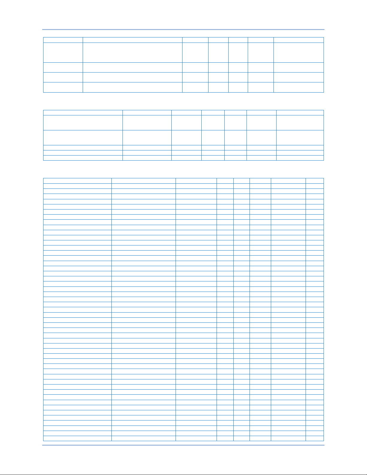
MBAP Header Description
The MBAP Header contains the fields listed in Table 2.
Table 2. MBAP Header Fields
Fields Length Description Client Server
Transaction
Identifier
Protocol
Identifier
Length 2 Bytes Number of following bytes.
Unit Identifier 1 Byte
The header is 7 bytes long:
• Transaction Identifier – Used for transacti on pairing, the Modbus serv er copies in the response
the transaction identifier of the request.
• Protocol Identifier – Used for intra-system multi plexing. The Modbus protocol is identified by the
value 0.
• Length – A byte count of the following fields, including the Unit Identifier and data fields.
• Unit Identifier – Used for intr a-system routing purpose. It is typic ally used to communicat e to a
Modbus or a Modbus serial line slav e through a gateway between an Ethernet TCP/I P network
and a Modbus serial line. This field is set by the Modbus Client in the request and must be
returned with the same value in the response by the server.
2 Bytes
2 Bytes 0 = Modbus protocol.
Identification of a Modbus
request/response transaction.
Identification of a remote slave
connected on a serial line or on
other buses.
Initialized by
the client.
Initialized by
the client.
Initialized by
the client
(request).
Initialized by
the client.
Recopied by the
server from the
received request.
Recopied by the
server from the
received request.
Initialized by the
server (response).
Recopied by the
server from the
received request.
Note: All Modbus/TCP ADU are sent via TCP on registered port 502.
Error Handling and Exception Responses
Any query received that contains a non-existent device address, a framing error, or CRC error is ignored.
No response is transmitted. Queries addressed to the BE1-11 with an unsupported function or illegal
values in the data block result in an error response message with an exception response code. The
exception response codes supported by the BE1-11 are provided in Table 3.
General Information BE1-11
Page 11

9424200774 Rev B 5
Table 3. Supported Exception Response Codes
Code Name Description
01 Illegal Function
02 Illegal Data Address
03 Illegal Data Value
The query Function/Subfunction Code is unsupported; query
read of more than 125 registers; query preset of more than 100
registers.
A register referenced in the data block does not support queried
read/write; query preset of a subset of a numerical register
group.
A preset register data block contains an incorrect number of
bytes or one or more data values out of range.
BE1-11 Modbus™ via Ethernet
Modbus can communicate through Ethernet if the IP address of the BE1-11 is configured as described in
the Communication chapter of the appropriate BE1-11 instruction ma nua l.
Communications Hardware Requirements
Modbus™ Over RS-485 Communication Requirements
The BE1-11 optional RS-485 physical interface is three positions of a terminal strip with locations for
Send/Receive A (A), Send/Receive B (B) and Signal Ground (C). Refer to the instruction manuals for the
BE1-11 protection systems for further details.
Modbus™ Over Ethernet TCP/IP Communication Requirements
The BE1-11 Ethernet port (RJ-45 or fiber optic) is used with the Ethernet option. The protection system
supports 10/100BASE-T using Cat 5 / Cat 5e shielded twisted pair on the RJ-45 port or 100MB/s on the
fiber optic port. Refer to the appropriate instruction manual for the BE1-11 for further details.
Detailed Message Query and Res pons e f or RTU Transmission Mode
A detailed description of BE1-11 supported mes s age queri es and respons es is pr ov ided in the follow in g
paragraphs.
Read Holding Registers
Query
This query message requests a register or block of registers to be read. The data block contains the starting
register addres s and the quant ity of regist ers to be rea d. A register address of N wi ll read holding register
N+1. If the query is a broadcast (device address = 0), no response message is returned.
Device Address
Function Code = 03 (hex)
Starting Address Hi
Starting Address Lo
No. of Registers Hi
No. of Registers Lo
CRC Hi error check
CRC Lo error check
The number of registers cannot exceed 125 without causing an error response with the exception code
for an illegal function.
BE1-11 General Information
Page 12

6 9424200774 Rev B
Response
The response message contains the data queried. The data block contains the block length in bytes
followed by the data (one Data Hi byte and one Data Lo byte) for each requested register.
Reading an unassigned holding register returns a value of zero.
Device Address
Function Code = 03 (hex)
Byte Count
Data Hi (For each requested register, there is one Data Hi and one Data Lo.)
Data Lo
.
.
Data Hi
Data Lo
CRC Hi error check
CRC Lo error check
Return Query Data
This query contains data to be returned (looped back) in the response. The response and query
messages should be identical. If the query is a broadcast (device address = 0), no response message is
returned.
Device Address
Function Code = 08 (hex)
Subfunction Hi = 00 (hex)
Subfunction Lo = 00 (hex)
Data Hi = xx (don't care)
Data Lo = xx (don't care)
CRC Hi error check
CRC Lo error check
Restart Communications Option
This query causes the remote communications function of the BE1-11 to restart, terminating an active
listen only mode of operation. No effect is made upon primary BE1-11 operations. Only the remote
communications function is affected. If the query is a broadcast (device address = 0), no response
message is returned.
If the BE1-11 receives this query while in the listen only mode, no response message is generated.
Otherwise, a response message identical to the query message is transmitted prior to the
communications restart.
Device Address
Function Code = 08 (hex)
Subfunction Hi = 00 (hex)
Subfunction Lo = 01 (hex)
Data Hi = xx (don't care)
Data Lo = xx (don't care)
CRC Hi error check
CRC Lo error check
Listen Only Mode
This query forces the addressed BE1-11 to the listen only mode for Modbus communications, isolating it
from other devices on the network. No responses are returned.
General Information BE1-11
Page 13

9424200774 Rev B 7
While in the listen only mode, the BE1-11 continues to monitor all queries. The BE1-11 does not respond
to any other query until the listen only mode is removed. All write requests with a query to Preset Multiple
Registers (Function Code = 16) are also ignored. When the BE1-11 receives the restart communications
query, the listen only mode is removed.
Device Address
Function Code = 08 (hex)
Subfunction Hi = 00 (hex)
Subfunction Lo = 04 (hex)
Data Hi = xx (don't care)
Data Lo = xx (don't care)
CRC Hi error check
CRC Lo error check
Preset Multiple Registers
A preset multiple registers query could address multiple registers in one slave or multiple slaves. If the
query is a broadcast (device address = 0), no response message is returned.
Query
A Preset Multiple Register query message requests a register or block of registers to be written. The data
block contains the starting address and the quantity of registers to be written, followed by the Data Block
byte count and data. The BE1-11 will perform the write when the device address in query is a broadcast
address or the same as the BE1-11 Modbus Unit ID (device address).
A register address of N will write Holding Register N+1.
Data will cease to be written if any of the following exceptions occur.
• Queries to write to Read Only r egisters result i n an err or res ponse with Ex cepti on Code of “I llegal
Data Address”.
• Queries attempting to write more than 100 registers cause an error response with Exception
Code “Illegal Function”.
• An incorrect Byte Count will result in an error response with Exception Code of “Illegal Data
Value”.
• There are several instances of registers that are grouped together to collectively represent a
single numerical BE1-11 d ata value (i.e. - floati ng point data, 32-bit integer data, and strings). A
query to write a subset o f such a register group will result in an error response with Except ion
Code “Illegal Data Address”.
• A query to write a not allo wed value (out of rang e) to a register resul ts in an error response w ith
Exception Code of “Illegal Data Value” .
Device Address
Function Code = 10 (hex)
Starting Address Hi
Starting Address Lo
No. of Registers Hi
No. of Registers Lo
Byte Count
Data Hi
Data Lo
.
.
Data Hi
Data Lo
CRC Hi error check
CRC Lo error check
BE1-11 General Information
Page 14

8 9424200774 Rev B
Response
The response message echoes the starting address and the number of registers. There is no response
message when the query is a broadcast (device address = 0).
Device Address
Function Code = 10 (hex)
Starting Address Hi
Starting Address Lo
No. of Registers Hi
No. of Registers Lo
CRC Hi Error Check
CRC Lo Error Check
Preset Single Register
A Preset Single Register query message requests a single register to be written. If the query is a
broadcast (device address = 0), no response message is returned.
Note: Only data types INT16, INT8, UINT16, UINT8, and String (not longer than 2 bytes), can be preset
by this function.
Query
Data will cease to be written if any of the following exceptions occur.
• Queries to write to Read Only r egisters result i n an err or res ponse with Ex cepti on Code of “I llegal
Data Address”.
• A query to write a disallow ed value (out of range) to a register results in an error response with
Exception Code of “Illegal Data Value” .
Device Address
Function Code = 06 (hex)
Address Hi
Address Lo
Data Hi
Data Lo
CRC Hi error check
CRC Lo error check
Response
The response message echoes the Query message after the register has been altered.
Data Formats
BE1-11 Protection Systems support the following data types:
● Data types mapped to 2 registers
○ Unsigned Integer 32 (Uint32)
○ Signed Integer 32 (Int32)
○ Floating Point (Float)
○ IP Address (IP Address )
○ Strings maximum 4 characters long (String)
● Data types mapped to 1 register
○ Unsigned Integer 1 6 (Uint16) (If this type is mapped to section Binar y Points, then 1 regist er
contains up to 16 b it-mapped variables as listed in the Regis ter Table chapter under Binary
Points.)
○ Signed Integer 16 (Int16)
○ Unsigned Integer 8 (Uint8)
General Information BE1-11
Page 15

9424200774 Rev B 9
Sign
Exponent + 127
Mantissa
○ Signed Integer 8 (Int8)
○ Strings maximum 2 characters long (String)
● Data types mapped to more than 2 registers
○ Strings longer than 4 characters (String)
Floating Point Data Format (Float)
The Modbus floating point data format uses two consecutive holding registers to represent a data value.
The first register contains the low-order 16 bits of the following 32-bit format:
• MSB is the sign bit for the floating-point value (0 = positive).
• The next 8 bits are the exponent biased by 127 decimal.
• The 23 LSBs comprise the normalized mantissa. The most-significant bit of the mantissa is
always assumed to be 1 and is not explicitly stored, yielding an effective precision of 24 bits.
The value of the floating-point number is obtained by multiplying the binary mantissa times two raised to
the power of the unbiased exponent. The assumed bit of the binary mantissa has the value of 1.0, with
the remaining 23 bits providing a fractional value. Table 4 shows the floating-point format.
Table 4. Floating Point Format
1 Bit 8 Bits 23 Bits
The floating-point format allows for values ranging from approximately 8.43X10
–37
to 3.38X1038. A floatingpoint value of all zeroes is the value zero. A floating-point value of all ones (not a number) signifies a
value currently not applicable or disabled.
Example: The value 95,800 represented in floating-point format is hexadecimal 47BB1C00. This number
will read from two consecutive holding registers as follows:
Holding Regi ste r Value
K (Hi Byte) hex 1C
K (Lo Byte) hex 00
K+1 (Hi Byte) hex 47
K+1 (Lo Byte) hex BB
The same byte alignments are required to write.
Long Integer Data Format (Uint32, Int32, and IP Address)
The Modbus long integer data format uses two consecutive holding registers to represent a 32-bit data
value. The first register contains the low-order 16 bits and the second register contains the high-order 16
bits.
Example: The value 95,800 represented in long integer format is hexadecimal 0x00017638. This number
will read from two consecutive holding registers as follows:
Holding Regi ste r Value
K (Hi Byte) hex 76
K (Lo Byte) hex 38
K+1 (Hi Byte) hex 00
K+1 (Lo Byte) hex 01
The same byte alignments are required to write.
Integer Data Format (Uint16 and Int16) or Bit-Mapped Variables in Uint16 Format
The Modbus integer data format uses a single holding register to represent a 16-bit data value.
Example: The value 4660 represented in integer format is hexadecimal 0x1234. This number will read from
a holding register as follows:
BE1-11 General Information
Page 16

10 9424200774 Rev B
Holding Regi ste r Value
K (Hi Byte) hex 12
K (Lo Byte) hex 34
The same byte alignments are required to write.
If Uint16 Data Format is listed in the Binary Points Section only, then each register contains up to 16 bit-
mapped variables as listed in the Register Table chapter under Binary Points.
Example: Register 900 occupies 16 rows in the Register Table where each row gives the name of specific
bit-mapped data such as 900-0 indicates bit 0 of register 900 is mapped to 60FL/60FL ALARM, bit 1 is
mapped to 27P/BLOCK, and so forth until 900-15 is mapped to 27P-2/BLOCK.
Short Integer Data Format/Byte Character Data Format (Uint8 and Int8)
The Modbus short integer data format uses a single holding register to represent an 8-bit data value. The
holding register high byte will always be zero.
Example: The value 132 repres ented in short i nteger format is hex adecimal 0x84. This number w ill read
from a holding register as follows:
Holding Regi ste r Value
K (Hi Byte) hex 00
K (Lo Byte) hex 84
The same byte alignments are required to write.
String Data Format (String)
The Modbus string data format uses one or more holding registers to represent a sequence, or string, of
character values. If the string contains a single character, the holding register high byte will contain the
ASCII character code and the low byte will be zero.
Example: The string “PASSWORD” represented in string format will read as follows:
Holding Register Value
K (Hi Byte) ‘P’
K (Lo Byte) ‘A’
K+1 (Hi Byte) ‘S’
K+1 (Lo Byte) ‘S’
K+2 (Hi Byte) ‘W’
K+2 (Lo Byte) ‘O’
K+3 (Hi Byte) ‘R’
K+3 (Lo Byte) ‘D’
Example: If the above string is changed to “P”, the new string will read as follows:
Holding Regi ste r Value
K (Hi Byte) ‘P’
K (Lo Byte) hex 00
K+1 (Hi Byte) hex 00
K+1 (Lo Byte) hex 00
K+2 (Hi Byte) hex 00
K+2 (Lo Byte) hex 00
K+3 (Hi Byte) hex 00
K+3 (Lo Byte) hex 00
The same byte alignments are required to write.
General Information BE1-11
Page 17

9424200774 Rev B 11
CRC Error Check
This field contains a 2-byte CRC value for transmission error detection. The master first calculates the
CRC and appends it to the query message. The BE1-11 Protection System recalculates the CRC value
for the received query and performs a comparison to the query CRC value to determine if a transmission
error has occurred. If so, no response message is generated. If no transmission error has occurred, the
slave calculates a new CRC value for the response message and appends it to the message for
transmission.
The CRC calculation is performed using all bytes of the device address, function code, and data block
fields. A 16-bit CRC register is initialized to all 1's. Then each 8-bit byte of the message is used in the
following algorithm:
First, exclusive-OR the message byte with the low-order byte of the CRC register. The result, stored in
the CRC register, will then be right-shifted eight times. The CRC register MSB is zero-filled with each
shift. After each shift, the CRC register LSB is examined. If the LSB is a 1, the CRC register is exclusiveORed with the fixed polynomial value A001 (hex) prior to the next shift. Once all bytes of the message
have undergone the above algorithm, the CRC register will contain the message CRC value to be placed
in the error check field.
Reading Fault Record Data
Fault record data is obtained by reading registers from the session fault record. The fault record to be
reported is selected by writing the fault number to register “Fault Report Selection”. See Fault Record
Setup in the Register Table chapter. The selected fault may be from 1 to 255. Entering a value of –1, will
select the most recent fault record.
Contiguous Poll Block Registers
The user may allocate up to 125 holding registers to the Contiguous Poll Block (9875-9999). This
allocation allows dispersed registers that are frequently read to be polled via a single read query. Mapping
can be done via BESTCOMSPlus or via Modbus registers in the Poll Block Settings session. A register is
assigned to a position in the Poll Block by writing its address value into the corresponding position in the
Contiguous Poll Block Assignments registers (9676-9800) in the Poll Block Settings session. Unassigned
position(s) must be mapped to Modbus Dummy Data register (9874), which always returns a value of 0.
Once assignments are made, the values of the assigned registers may be read by polling the Contiguous
Poll Block. For example, if you wanted to continuously monitor VA Primary (10100), IA Pri m ar y (10124),
IA Angle (10126), and Total PF (10192) Holding Registers, you would first configure the Contiguous Poll
Block Registers by writing the desired register address values 10100, 10101, 10124, 10125, 10126,
10127, 10192, and 10193 into the Contiguous Poll Block Assignment registers 9676 thru 9683,
respectively. You may now begin monitoring the specified registers by reading the first 8 locations in the
Contiguous Poll Block; ie, reading registers 9875/9876 for VA Primary (as specified in its corresponding
assignment registers 9676/9677), reading registers 9876/9877 for IA Primary (as specified in its
corresponding assignment registers 9678/9679), reading registers 9879/9880 for IA Angle (as specified in
its corresponding assignment registers 9680/9681), and reading registers 9881/9882 for Total PF (as
specified in its corresponding assignment registers 9682/9683).
BE1-11 General Information
Page 18

12 9424200774 Rev B
General Information BE1-11
Page 19

9424200774 Rev B 13
Name
Description
Register
Type
Bytes
Writable
Range
System Data
Default Graphics Module Version
1
String
13 R 0 - 13
System Data
Alternate Graphics Module Version
8
String
13 R 0 - 13
System Data
Model Number
15
String
64 R 0 - 64
Reserved
47-110
System Data
Boot Version Information
111
String
64 R 0 - 64
Reserved
143-206
System Data
Firmware Part Number
207
String
64 R 0 - 64
Unit Info
Style Number
239
String
32 R 0 - 32
Unit Info
Model Number
255
String
64 R 0 - 64
Unit Info
App Part Number
287
String
64 R 0 - 64
Unit Info
Serial Number
319
String
32 R 0 - 32
Register Table
Parameters are mapped into the holding register address space in blocks according to access type.
Registers 9875 through 9999 are reserved for user configurable polling block, and register 9874 is
reserved for system use only. By default, all registers in the polling block are mapped to register 9874
when their value is zero. Use BESTCOMSPlus® to map desired data to poll block registers to be read by
one Modbus™ read request.
Any holding register not listed in the register table is an unassigned holding register. Reading or writing to
unassigned holding registers is not allowed and error code “Illegal Data Address” will be reported.
Reading/Writing any data (variable) as its complete (atomic) value is the only legal operation. Partially
requested data will return an error. For example, request for reading/writing of/to only register 620 will
return an error because this register is part of data Settings Group-Direct Operate that is mapped to 2
registers. Reading of register 620 is correct only if reading/writing of both 620 and 621 are requested in
the same query.
Conventions
The Type column uses the following abbreviations:
• String - ASCII string
• Float - Floating point
• Int32 - Integer (32-bit integ er )
• Int16 - Integer (16-bit int eg er)
• Int8 - Integer (8-bit integer)
• Uint32 - Unsigned Integer (32-bit integer)
• Uint16 - Unsigned Integer (16-bit integer)
• Uint8 - Unsigned Integer (8-bit integer)
• IP Address - IP Address
The Style column uses the following abbreviations:
• F - Feeder Protection System
• G - Generator Protection System
• I - Intertie Protection System
• M - Motor Protection System
• T - Transformer Protection System
Register Table
The register table on the following pages contains the following groups:
General, SBO Select, SBO Operate, Direct Operate, Binary Points, Reporting, Power Quality, Fault
Record, Relay Settings, Reporting Setup, Power Quality Setup, Demand Setup, Fault Record Setup, Poll
Block Settings, Metering, Deman d Data, Global Settings, Protection Settings, and User Labels.
General
BE1-11 Register Table
Page 20

14 9424200774 Rev B
Name
Description
Register
Type
Bytes
Writable
Range
43-1
Select
600
Uint32
4
R W
Set=1
Pulse=3
43-2
Select
602
Uint32
4
R W
Set=1
Pulse=3
43-3
Select
604
Uint32
4
R W
Set=1
Pulse=3
43-4
Select
606
Uint32
4
R W
Set=1
Pulse=3
43-5
Select
608
Uint32
4
R W
Set=1
Pulse=3
101
Select
610
Uint32
4
R W
Trip=1
Close=2
Local Contacts
Contact Output 1 Override State Select
612
Uint8 1 R W
Off=0
On=1
Local Contacts
Contact Output 2 Override State Select
613
Uint8 1 R W
Off=0
On=1
Local Contacts
Contact Output 3 Override State Select
614
Uint8 1 R W
Off=0
On=1
Local Contacts
Contact Output 4 Override State Select
615
Uint8 1 R W
Off=0
On=1
Local Contacts
Contact Output 5 Override State Select
616
Uint8 1 R W
Off=0
On=1
Local Contacts
Contact Output A Override State Select
617
Uint8 1 R W
Off=0
On=1
Settings Group
Select
618
Int32 4 R W
Settings Group 0=0
Settings Group 3=3
Settings Group
Direct Operate
620
Int32 4 R W
Settings Group 0=0
Settings Group 3=3
Local Contacts
Contact Output 6 Override State Select
622
Uint8 1 R W
Off=0
On=1
Local Contacts
Contact Output 7 Override State Select
623
Uint8 1 R W
Off=0
On=1
Local Contacts
Contact Output 8 Override State Select
624
Uint8 1 R W
Off=0
On=1
Name
Description
Register
Type
Bytes
Writable
Range
43-1
Operate
700
Uint32
4
R W
Set=1
Pulse=3
43-2
Operate
702
Uint32
4
R W
Set=1
Pulse=3
43-3
Operate
704
Uint32
4
R W
Set=1
Pulse=3
43-4
Operate
706
Uint32
4
R W
Set=1
Pulse=3
43-5
Operate
708
Uint32
4
R W
Set=1
Pulse=3
101
Operate
710
Uint32
4
R W
Trip=1
Close=2
Local Contacts
Contact Output 1 Override State Operate
712
Uint8 1 R W
Off=0
On=1
Local Contacts
Contact Output 2 Override State Operate
713
Uint8 1 R W
Off=0 On=1
Local Contacts
Contact Output 3 Override State Operate
714
Uint8 1 R W
Off=0
On=1
Local Contacts
Contact Output 4 Override State Operate
715
Uint8 1 R W
Off=0
On=1
Local Contacts
Contact Output 5 Override State Operate
716
Uint8 1 R W
Off=0
On=1
Local Contacts
Contact Output A Override State Operate
717
Uint8 1 R W
Off=0
On=1
SBO Select
Reset=2
Reset=2
Reset=2
Reset=2
Reset=2
SBO Operate
Settings Group 1=1
Settings Group 2=2
Settings Group 1=1
Settings Group 2=2
Reset=2
Reset=2
Reset=2
Reset=2
Reset=2
Register Table BE1-11
Page 21
9424200774 Rev B 15
Name
Description
Register
Type
Bytes
Writable
Range
Settings Group
Operate
718
Int32 4 R W
Settings Group 0=0
Settings Group 3=3
Local Contacts
Contact Output 6 Override State Operate
720
Uint8 1 R W
Off=0
On=1
Local Contacts
Contact Output 7 Override State Operate
721
Uint8 1 R W
Off=0
On=1
Local Contacts
Contact Output 8 Override State Operate
722
Uint8 1 R W
Off=0
On=1
Name
Description
Register
Type
Bytes
Writable
Range
101
Untag
800
Uint32
4
R W
Disable Tag=0
Blocking Tag=2
101
Tag
802
Uint32
4
R W
Disable Tag=0
Blocking Tag=2
Demand Meter Circuit 1
Reset Demands
804
Uint32
4
R W
Operate=1
Current Demand Circuit 2
Reset Demands
806
Uint32
4
R W
Operate=1
G Current Demand Circuit 2
Reset Demands
808
Uint32
4
R W
Operate=1
Name
Description
Register
Type
Bytes
Writable
Range
Style
60FL
60FL Alarm
900 bit 0
Uint16
2 R True=1 False=0
FGIMT
24
Block
900 bit 1
Uint16
2 R True=1 False=0
GIT
24
Pickup
900 bit 2
Uint16
2 R True=1 False=0
GIT
24
Trip
900 bit 3
Uint16
2 R True=1 False=0
GIT
24
Target
900 bit 4
Uint16
2 R True=1 False=0
GIT
24
Alarm
900 bit 5
Uint16
2 R True=1 False=0
GIT
25
Block
900 bit 6
Uint16
2 R True=1 False=0
FGI
25
Status
900 bit 7
Uint16
2 R True=1 False=0
FGI
25
VM1 Status
900 bit 8
Uint16
2 R True=1 False=0
FGI
27P-1
Block
900 bit 9
Uint16
2 R True=1 False=0
FGIMT
27P-1
Pickup
900 bit 10
Uint16
2 R True=1 False=0
FGIMT
27P-1
Trip
900 bit 11
Uint16
2 R True=1 False=0
FGIMT
27P-1
Target A
900 bit 12
Uint16
2 R True=1 False=0
FGIMT
27P-1
Target B
900 bit 13
Uint16
2 R True=1 False=0
FGIMT
27P-1
Target C
900 bit 14
Uint16
2 R True=1 False=0
FGIMT
27P-2
Block
900 bit 15
Uint16
2 R True=1 False=0
FGIMT
27P-2
Pickup
901 bit 0
Uint16
2 R True=1 False=0
FGIMT
27P-2
Trip
901 bit 1
Uint16
2 R True=1 False=0
FGIMT
27P-2
Target A
901 bit 2
Uint16
2 R True=1 False=0
FGIMT
27P-2
Target B
901 bit 3
Uint16
2 R True=1 False=0
FGIMT
27P-2
Target C
901 bit 4
Uint16
2 R True=1 False=0
FGIMT
27P-3
Block
901 bit 5
Uint16
2 R True=1 False=0
FGIMT
27P-3
Pickup
901 bit 6
Uint16
2 R True=1 False=0
FGIMT
27P-3
Trip
901 bit 7
Uint16
2 R True=1 False=0
FGIMT
27P-3
Target A
901 bit 8
Uint16
2 R True=1 False=0
FGIMT
27P-3
Target B
901 bit 9
Uint16
2 R True=1 False=0
FGIMT
27P-3
Target C
901 bit 10
Uint16
2 R True=1 False=0
FGIMT
27P-4
Block
901 bit 11
Uint16
2 R True=1 False=0
FGIMT
27P-4
Pickup
901 bit 12
Uint16
2 R True=1 False=0
FGIMT
27P-4
Trip
901 bit 13
Uint16
2 R True=1 False=0
FGIMT
27P-4
Target A
901 bit 14
Uint16
2 R True=1 False=0
FGIMT
27P-4
Target B
901 bit 15
Uint16
2 R True=1 False=0
FGIMT
27P-4
Target C
902 bit 0
Uint16
2 R True=1 False=0
FGIMT
27P-5
Block
902 bit 1
Uint16
2 R True=1 False=0
FGIT
27P-5
Pickup
902 bit 2
Uint16
2 R True=1 False=0
FGIT
27P-5
Trip
902 bit 3
Uint16
2 R True=1 False=0
FGIT
27P-5
Target A
902 bit 4
Uint16
2 R True=1 False=0
FGIT
27P-5
Target B
902 bit 5
Uint16
2 R True=1 False=0
FGIT
27P-5
Target C
902 bit 6
Uint16
2 R True=1 False=0
FGIT
27X-1
Block
902 bit 7
Uint16
2 R True=1 False=0
FGIT
27X-1
Pickup
902 bit 8
Uint16
2 R True=1 False=0
FGIT
27X-1
Trip
902 bit 9
Uint16
2 R True=1 False=0
FGIT
27X-1
Target 3V0
902 bit 10
Uint16
2 R True=1 False=0
FGIT
27X-1
Target V2
902 bit 11
Uint16
2 R True=1 False=0
FGIT
27X-1
Target AUX
902 bit 12
Uint16
2 R True=1 False=0
FGIT
27X-1
Target 3RD
902 bit 13
Uint16
2 R True=1 False=0
FGIT
27X-1
Target V1
902 bit 14
Uint16
2 R True=1 False=0
FGIT
27X-2
Block
902 bit 15
Uint16
2 R True=1 False=0
FGIT
27X-2
Pickup
903 bit 0
Uint16
2 R True=1 False=0
FGIT
27X-2
Trip
903 bit 1
Uint16
2 R True=1 False=0
FGIT
Settings Group 1=1
Settings Group 2=2
Direct Operate
Info Tag=1
Info Tag=1
Binary Points
BE1-11 Register Table
Page 22

16 9424200774 Rev B
Name
Description
Register
Type
Bytes
Writable
Range
Style
27X-2
Target 3V0
903 bit 2
Uint16
2 R True=1 False=0
FGIT
27X-2
Target V2
903 bit 3
Uint16
2 R True=1 False=0
FGIT
27X-2
Target AUX
903 bit 4
Uint16
2 R True=1 False=0
FGIT
27X-2
Target 3RD
903 bit 5
Uint16
2 R True=1 False=0
FGIT
27X-2
Target V1
903 bit 6
Uint16
2 R True=1 False=0
FGIT
27X-3
Block
903 bit 7
Uint16
2 R True=1 False=0
FGIT
27X-3
Pickup
903 bit 8
Uint16
2 R True=1 False=0
FGIT
27X-3
Trip
903 bit 9
Uint16
2 R True=1 False=0
FGIT
27X-3
Target 3V0
903 bit 10
Uint16
2 R True=1 False=0
FGIT
27X-3
Target V2
903 bit 11
Uint16
2 R True=1 False=0
FGIT
27X-3
Target AUX
903 bit 12
Uint16
2 R True=1 False=0
FGIT
27X-3
Target 3RD
903 bit 13
Uint16
2 R True=1 False=0
FGIT
27X-3
Target V1
903 bit 14
Uint16
2 R True=1 False=0
FGIT
27X-4
Block
903 bit 15
Uint16
2 R True=1 False=0
FGIT
27X-4
Pickup
904 bit 0
Uint16
2 R True=1 False=0
FGIT
27X-4
Trip
904 bit 1
Uint16
2 R True=1 False=0
FGIT
27X-4
Target 3V0
904 bit 2
Uint16
2 R True=1 False=0
FGIT
27X-4
Target V2
904 bit 3
Uint16
2 R True=1 False=0
FGIT
27X-4
Target AUX
904 bit 4
Uint16
2 R True=1 False=0
FGIT
27X-4
Target 3RD
904 bit 5
Uint16
2 R True=1 False=0
FGIT
27X-4
Target V1
904 bit 6
Uint16
2 R True=1 False=0
FGIT
59P-1
Block
904 bit 7
Uint16
2 R True=1 False=0
FGIMT
59P-1
Pickup
904 bit 8
Uint16
2 R True=1 False=0
FGIMT
59P-1
Trip
904 bit 9
Uint16
2 R True=1 False=0
FGIMT
59P-1
Target A
904 bit 10
Uint16
2 R True=1 False=0
FGIMT
59P-1
Target B
904 bit 11
Uint16
2 R True=1 False=0
FGIMT
59P-1
Target C
904 bit 12
Uint16
2 R True=1 False=0
FGIMT
59P-2
Block
904 bit 13
Uint16
2 R True=1 False=0
FGIMT
59P-2
Pickup
904 bit 14
Uint16
2 R True=1 False=0
FGIMT
59P-2
Trip
904 bit 15
Uint16
2 R True=1 False=0
FGIMT
59P-2
Target A
905 bit 0
Uint16
2 R True=1 False=0
FGIMT
59P-2
Target B
905 bit 1
Uint16
2 R True=1 False=0
FGIMT
59P-2
Target C
905 bit 2
Uint16
2 R True=1 False=0
FGIMT
59P-3
Block
905 bit 3
Uint16
2 R True=1 False=0
FGIT
59P-3
Pickup
905 bit 4
Uint16
2 R True=1 False=0
FGIT
59P-3
Trip
905 bit 5
Uint16
2 R True=1 False=0
FGIT
59P-3
Target A
905 bit 6
Uint16
2 R True=1 False=0
FGIT
59P-3
Target B
905 bit 7
Uint16
2 R True=1 False=0
FGIT
59P-3
Target C
905 bit 8
Uint16
2 R True=1 False=0
FGIT
59P-4
Block
905 bit 9
Uint16
2 R True=1 False=0
FGIT
59P-4
PICKUP
905 bit 10
Uint16
2 R True=1 False=0
FGIT
59P-4
Trip
905 bit 11
Uint16
2 R True=1 False=0
FGIT
59P-4
Target A
905 bit 12
Uint16
2 R True=1 False=0
FGIT
59P-4
Target B
905 bit 13
Uint16
2 R True=1 False=0
FGIT
59P-4
Target C
905 bit 14
Uint16
2 R True=1 False=0
FGIT
59X-1
Block
905 bit 15
Uint16
2 R True=1 False=0
FGIMT
59X-1
Pickup
906 bit 0
Uint16
2 R True=1 False=0
FGIMT
59X-1
Trip
906 bit 1
Uint16
2 R True=1 False=0
FGIMT
59X-1
Target 3V0
906 bit 2
Uint16
2 R True=1 False=0
FGIMT
59X-1
Target V2
906 bit 3
Uint16
2 R True=1 False=0
FGIMT
59X-1
Target AUX
906 bit 4
Uint16
2 R True=1 False=0
FGIMT
59X-1
Target 3RD
906 bit 5
Uint16
2 R True=1 False=0
FGIMT
59X-1
Target V1
906 bit 6
Uint16
2 R True=1 False=0
FGIMT
59X-2
Block
906 bit 7
Uint16
2 R True=1 False=0
FGIMT
59X-2
Pickup
906 bit 8
Uint16
2 R True=1 False=0
FGIMT
59X-2
Trip
906 bit 9
Uint16
2 R True=1 False=0
FGIMT
59X-2
Target 3V0
906 bit 10
Uint16
2 R True=1 False=0
FGIMT
59X-2
Target V2
906 bit 11
Uint16
2 R True=1 False=0
FGIMT
59X-2
Target AUX
906 bit 12
Uint16
2 R True=1 False=0
FGIMT
59X-2
Target 3RD
906 bit 13
Uint16
2 R True=1 False=0
FGIMT
59X-2
Target V1
906 bit 14
Uint16
2 R True=1 False=0
FGIMT
59X-3
BLOCK
906 bit 15
Uint16
2 R True=1 False=0
FGIT
59X-3
PICKUP
907 bit 0
Uint16
2 R True=1 False=0
FGIT
59X-3
TRIP
907 bit 1
Uint16
2 R True=1 False=0
FGIT
59X-3
Target 3V0
907 bit 2
Uint16
2 R True=1 False=0
FGIT
59X-3
Target V2
907 bit 3
Uint16
2 R True=1 False=0
FGIT
59X-3
Target AUX
907 bit 4
Uint16
2 R True=1 False=0
FGIT
59X-3
Target 3RD
907 bit 5
Uint16
2 R True=1 False=0
FGIT
59X-3
Target V1
907 bit 6
Uint16
2 R True=1 False=0
FGIT
59X-4
Block
907 bit 7
Uint16
2 R True=1 False=0
FGIT
59X-4
Pickup
907 bit 8
Uint16
2 R True=1 False=0
FGIT
59X-4
Trip
907 bit 9
Uint16
2 R True=1 False=0
FGIT
59X-4
Target 3V0
907 bit 10
Uint16
2 R True=1 False=0
FGIT
59X-4
Target V2
907 bit 11
Uint16
2 R True=1 False=0
FGIT
59X-4
Target AUX
907 bit 12
Uint16
2 R True=1 False=0
FGIT
59X-4
Target 3RD
907 bit 13
Uint16
2 R True=1 False=0
FGIT
59X-4
Target V1
907 bit 14
Uint16
2 R True=1 False=0
FGIT
50-1
Block
907 bit 15
Uint16
2 R True=1 False=0
FGIMT
Register Table BE1-11
Page 23

9424200774 Rev B 17
Name
Description
Register
Type
Bytes
Writable
Range
Style
50-1
Pickup
908 bit 0
Uint16
2 R True=1 False=0
FGIMT
50-1
Trip
908 bit 1
Uint16
2 R True=1 False=0
FGIMT
50-1
Target A
908 bit 2
Uint16
2 R True=1 False=0
FGIMT
50-1
Target B
908 bit 3
Uint16
2 R True=1 False=0
FGIMT
50-1
Target C
908 bit 4
Uint16
2 R True=1 False=0
FGIMT
50-1
Target Negative Sequence
908 bit 5
Uint16
2 R True=1 False=0
FGIMT
50-1
Target Residual
908 bit 6
Uint16
2 R True=1 False=0
FGIMT
50-1
Target Independent Ground
908 bit 7
Uint16
2 R True=1 False=0
FGIMT
50-1
67 Target A
908 bit 8
Uint16
2 R True=1 False=0
FGIT
50-1
67 Target B
908 bit 9
Uint16
2 R True=1 False=0
FGIT
50-1
67 Target C
908 bit 10
Uint16
2 R True=1 False=0
FGIT
50-1
67 Target Negative Sequence
908 bit 11
Uint16
2 R True=1 False=0
FGIT
50-1
67 Target Residual
908 bit 12
Uint16
2 R True=1 False=0
FGIT
50-1
67 Target Independent Gr ou nd
908 bit 13
Uint16
2 R True=1 False=0
FGIT
50-2
Block
908 bit 14
Uint16
2 R True=1 False=0
FGIMT
50-2
Pickup
908 bit 15
Uint16
2 R True=1 False=0
FGIMT
50-2
Trip
909 bit 0
Uint16
2 R True=1 False=0
FGIMT
50-2
Target A
909 bit 1
Uint16
2 R True=1 False=0
FGIMT
50-2
Target B
909 bit 2
Uint16
2 R True=1 False=0
FGIMT
50-2
Target C
909 bit 3
Uint16
2 R True=1 False=0
FGIMT
50-2
Target Negative Sequence
909 bit 4
Uint16
2 R True=1 False=0
FGIMT
50-2
Target Residual
909 bit 5
Uint16
2 R True=1 False=0
FGIMT
50-2
Target Independent Ground
909 bit 6
Uint16
2 R True=1 False=0
FGIMT
50-2
67 Target A
909 bit 7
Uint16
2 R True=1 False=0
FGIT
50-2
67 Target B
909 bit 8
Uint16
2 R True=1 False=0
FGIT
50-2
67 Target C
909 bit 9
Uint16
2 R True=1 False=0
FGIT
50-2
67 Target Negative Sequence
909 bit 10
Uint16
2 R True=1 False=0
FGIT
50-2
67 Target Residual
909 bit 11
Uint16
2 R True=1 False=0
FGIT
50-2
67 Target Independent Gr ou nd
909 bit 12
Uint16
2 R True=1 False=0
FGIT
50-3
Block
909 bit 13
Uint16
2 R True=1 False=0
FGIMT
50-3
Pickup
909 bit 14
Uint16
2 R True=1 False=0
FGIMT
50-3
Trip
909 bit 15
Uint16
2 R True=1 False=0
FGIMT
50-3
Target A
910 bit 0
Uint16
2 R True=1 False=0
FGIMT
50-3
Target B
910 bit 1
Uint16
2 R True=1 False=0
FGIMT
50-3
Target C
910 bit 2
Uint16
2 R True=1 False=0
FGIMT
50-3
Target Negative Sequence
910 bit 3
Uint16
2 R True=1 False=0
FGIMT
50-3
Target Residual
910 bit 4
Uint16
2 R True=1 False=0
FGIMT
50-3
Target Independent Ground
910 bit 5
Uint16
2 R True=1 False=0
FGIMT
50-3
67 Target A
910 bit 6
Uint16
2 R True=1 False=0
FGIT
50-3
67 Target B
910 bit 7
Uint16
2 R True=1 False=0
FGIT
50-3
67 Target C
910 bit 8
Uint16
2 R True=1 False=0
FGIT
50-3
67 Target Negative Sequence
910 bit 9
Uint16
2 R True=1 False=0
FGIT
50-3
67 Target Residual
910 bit 10
Uint16
2 R True=1 False=0
FGIT
50-3
67 Target Independent Gr ou nd
910 bit 11
Uint16
2 R True=1 False=0
FGIT
50-4
Block
910 bit 12
Uint16
2 R True=1 False=0
FGIMT
50-4
Pickup
910 bit 13
Uint16
2 R True=1 False=0
FGIMT
50-4
Trip
910 bit 14
Uint16
2 R True=1 False=0
FGIMT
50-4
Target A
910 bit 15
Uint16
2 R True=1 False=0
FGIMT
50-4
Target B
911 bit 0
Uint16
2 R True=1 False=0
FGIMT
50-4
Target C
911 bit 1
Uint16
2 R True=1 False=0
FGIMT
50-4
Target Negative Sequence
911 bit 2
Uint16
2 R True=1 False=0
FGIMT
50-4
Target Residual
911 bit 3
Uint16
2 R True=1 False=0
FGIMT
50-4
Target Independent Ground
911 bit 4
Uint16
2 R True=1 False=0
FGIMT
50-4
67 Target A
911 bit 5
Uint16
2 R True=1 False=0
FGIT
50-4
67 Target B
911 bit 6
Uint16
2 R True=1 False=0
FGIT
50-4
67 Target C
911 bit 7
Uint16
2 R True=1 False=0
FGIT
50-4
67 Target Negative Sequence
911 bit 8
Uint16
2 R True=1 False=0
FGIT
50-4
67 Target Residual
911 bit 9
Uint16
2 R True=1 False=0
FGIT
50-4
67 Target Independent Gr ou nd
911 bit 10
Uint16
2 R True=1 False=0
FGIT
50-5
Block
911 bit 11
Uint16
2 R True=1 False=0
FGIMT
50-5
Pickup
911 bit 12
Uint16
2 R True=1 False=0
FGIMT
50-5
Trip
911 bit 13
Uint16
2 R True=1 False=0
FGIMT
50-5
Target A
911 bit 14
Uint16
2 R True=1 False=0
FGIMT
50-5
Target B
911 bit 15
Uint16
2 R True=1 False=0
FGIMT
50-5
Target C
912 bit 0
Uint16
2 R True=1 False=0
FGIMT
50-5
Target Negative Sequence
912 bit 1
Uint16
2 R True=1 False=0
FGIMT
50-5
Target Residual
912 bit 2
Uint16
2 R True=1 False=0
FGIMT
50-5
Target Independent Ground
912 bit 3
Uint16
2 R True=1 False=0
FGIMT
50-5
67 Target A
912 bit 4
Uint16
2 R True=1 False=0
FGIT
50-5
67 Target B
912 bit 5
Uint16
2 R True=1 False=0
FGIT
50-5
67 Target C
912 bit 6
Uint16
2 R True=1 False=0
FGIT
50-5
67 Target Negative Sequence
912 bit 7
Uint16
2 R True=1 False=0
FGIT
50-5
67 Target Residual
912 bit 8
Uint16
2 R True=1 False=0
FGIT
50-5
67 Target Independent Gr ou nd
912 bit 9
Uint16
2 R True=1 False=0
FGIT
50-6
Block
912 bit 10
Uint16
2 R True=1 False=0
FGIMT
50-6
Pickup
912 bit 11
Uint16
2 R True=1 False=0
FGIMT
50-6
Trip
912 bit 12
Uint16
2 R True=1 False=0
FGIMT
50-6
Target A
912 bit 13
Uint16
2 R True=1 False=0
FGIMT
BE1-11 Register Table
Page 24

18 9424200774 Rev B
Name
Description
Register
Type
Bytes
Writable
Range
Style
50-6
Target B
912 bit 14
Uint16
2 R True=1 False=0
FGIMT
50-6
Target C
912 bit 15
Uint16
2 R True=1 False=0
FGIMT
50-6
Target Negative Sequence
913 bit 0
Uint16
2 R True=1 False=0
FGIMT
50-6
Target Residual
913 bit 1
Uint16
2 R True=1 False=0
FGIMT
50-6
Target Independent Ground
913 bit 2
Uint16
2 R True=1 False=0
FGIMT
50-6
67 Target A
913 bit 3
Uint16
2 R True=1 False=0
FGIT
50-6
67 Target B
913 bit 4
Uint16
2 R True=1 False=0
FGIT
50-6
67 Target C
913 bit 5
Uint16
2 R True=1 False=0
FGIT
50-6
67 Target Negative Sequence
913 bit 6
Uint16
2 R True=1 False=0
FGIT
50-6
67 Target Residual
913 bit 7
Uint16
2 R True=1 False=0
FGIT
50-6
67 Target Independent Gr ou nd
913 bit 8
Uint16
2 R True=1 False=0
FGIT
51-1
Block
913 bit 9
Uint16
2 R True=1 False=0
FGIMT
51-1
Pickup
913 bit 10
Uint16
2 R True=1 False=0
FGIMT
51-1
Trip
913 bit 11
Uint16
2 R True=1 False=0
FGIMT
51-1
Target A
913 bit 12
Uint16
2 R True=1 False=0
FGIMT
51-1
Target B
913 bit 13
Uint16
2 R True=1 False=0
FGIMT
51-1
Target C
913 bit 14
Uint16
2 R True=1 False=0
FGIMT
51-1
Target Negative Sequence
913 bit 15
Uint16
2 R True=1 False=0
FGIMT
51-1
Target Residual
914 bit 0
Uint16
2 R True=1 False=0
FGIMT
51-1
Target Independent Ground
914 bit 1
Uint16
2 R True=1 False=0
FGIMT
51-1
67 Target A
914 bit 2
Uint16
2 R True=1 False=0
FGIT
51-1
67 Target B
914 bit 3
Uint16
2 R True=1 False=0
FGIT
51-1
67 Target C
914 bit 4
Uint16
2 R True=1 False=0
FGIT
51-1
67 Target NEG SEQ
914 bit 5
Uint16
2 R True=1 False=0
FGIT
51-1
67 Target Residual
914 bit 6
Uint16
2 R True=1 False=0
FGIT
51-1
67 Target Independent Gr ou nd
914 bit 7
Uint16
2 R True=1 False=0
FGIT
51-2
Block
914 bit 8
Uint16
2 R True=1 False=0
FGIMT
51-2
Pickup
914 bit 9
Uint16
2 R True=1 False=0
FGIMT
51-2
Trip
914 bit 10
Uint16
2 R True=1 False=0
FGIMT
51-2
Target A
914 bit 11
Uint16
2 R True=1 False=0
FGIMT
51-2
Target B
914 bit 12
Uint16
2 R True=1 False=0
FGIMT
51-2
Target C
914 bit 13
Uint16
2 R True=1 False=0
FGIMT
51-2
Target Negative Sequence
914 bit 14
Uint16
2 R True=1 False=0
FGIMT
51-2
Target Residual
914 bit 15
Uint16
2 R True=1 False=0
FGIMT
51-2
Target Independent Ground
915 bit 0
Uint16
2 R True=1 False=0
FGIMT
51-2
67 Target A
915 bit 1
Uint16
2 R True=1 False=0
FGIT
51-2
67 Target B
915 bit 2
Uint16
2 R True=1 False=0
FGIT
51-2
67 Target C
915 bit 3
Uint16
2 R True=1 False=0
FGIT
51-2
67 Target NEG SEQ
915 bit 4
Uint16
2 R True=1 False=0
FGIT
51-2
67 Target Residual
915 bit 5
Uint16
2 R True=1 False=0
FGIT
51-2
67 Target Independent Gr ou nd
915 bit 6
Uint16
2 R True=1 False=0
FGIT
51-3
Block
915 bit 7
Uint16
2 R True=1 False=0
FGIMT
51-3
Pickup
915 bit 8
Uint16
2 R True=1 False=0
FGIMT
51-3
Trip
915 bit 9
Uint16
2 R True=1 False=0
FGIMT
51-3
Target A
915 bit 10
Uint16
2 R True=1 False=0
FGIMT
51-3
Target B
915 bit 11
Uint16
2 R True=1 False=0
FGIMT
51-3
Target C
915 bit 12
Uint16
2 R True=1 False=0
FGIMT
51-3
Target Negative Sequence
915 bit 13
Uint16
2 R True=1 False=0
FGIMT
51-3
Target Residual
915 bit 14
Uint16
2 R True=1 False=0
FGIMT
51-3
Target Independent Ground
915 bit 15
Uint16
2 R True=1 False=0
FGIMT
51-3
67 Target A
916 bit 0
Uint16
2 R True=1 False=0
FGIT
51-3
67 Target B
916 bit 1
Uint16
2 R True=1 False=0
FGIT
51-3
67 Target C
916 bit 2
Uint16
2 R True=1 False=0
FGIT
51-3
67 Target Negative Sequence
916 bit 3
Uint16
2 R True=1 False=0
FGIT
51-3
67 Target Residual
916 bit 4
Uint16
2 R True=1 False=0
FGIT
51-3
67 Target Independent Gr ou nd
916 bit 5
Uint16
2 R True=1 False=0
FGIT
51-4
Block
916 bit 6
Uint16
2 R True=1 False=0
FGIMT
51-4
Pickup
916 bit 7
Uint16
2 R True=1 False=0
FGIMT
51-4
Trip
916 bit 8
Uint16
2 R True=1 False=0
FGIMT
51-4
Target A
916 bit 9
Uint16
2 R True=1 False=0
FGIMT
51-4
Target B
916 bit 10
Uint16
2 R True=1 False=0
FGIMT
51-4
Target C
916 bit 11
Uint16
2 R True=1 False=0
FGIMT
51-4
Target Negative Sequence
916 bit 12
Uint16
2 R True=1 False=0
FGIMT
51-4
Target Residual
916 bit 13
Uint16
2 R True=1 False=0
FGIMT
51-4
Target Independent Ground
916 bit 14
Uint16
2 R True=1 False=0
FGIMT
51-4
67 Target A
916 bit 15
Uint16
2 R True=1 False=0
FGIT
51-4
67 Target B
917 bit 0
Uint16
2 R True=1 False=0
FGIT
51-4
67 Target C
917 bit 1
Uint16
2 R True=1 False=0
FGIT
51-4
67 Target Negative Sequence
917 bit 2
Uint16
2 R True=1 False=0
FGIT
51-4
67 Target Residual
917 bit 3
Uint16
2 R True=1 False=0
FGIT
51-4
67 Target Independent Gr ou nd
917 bit 4
Uint16
2 R True=1 False=0
FGIT
51-5
Block
917 bit 5
Uint16
2 R True=1 False=0
FGIMT
51-5
Pickup
917 bit 6
Uint16
2 R True=1 False=0
FGIMT
51-5
Trip
917 bit 7
Uint16
2 R True=1 False=0
FGIMT
51-5
Target A
917 bit 8
Uint16
2 R True=1 False=0
FGIMT
51-5
Target B
917 bit 9
Uint16
2 R True=1 False=0
FGIMT
51-5
Target C
917 bit 10
Uint16
2 R True=1 False=0
FGIMT
51-5
Target Negative Sequence
917 bit 11
Uint16
2 R True=1 False=0
FGIMT
Register Table BE1-11
Page 25

9424200774 Rev B 19
Name
Description
Register
Type
Bytes
Writable
Range
Style
51-5
Target Residual
917 bit 12
Uint16
2 R True=1 False=0
FGIMT
51-5
Target Independent Ground
917 bit 13
Uint16
2 R True=1 False=0
FGIMT
51-5
67 Target A
917 bit 14
Uint16
2 R True=1 False=0
FGIT
51-5
67 Target B
917 bit 15
Uint16
2 R True=1 False=0
FGIT
51-5
67 Target C
918 bit 0
Uint16
2 R True=1 False=0
FGIT
51-5
67 Target Negative Sequence
918 bit 1
Uint16
2 R True=1 False=0
FGIT
51-5
67 Target Residual
918 bit 2
Uint16
2 R True=1 False=0
FGIT
51-5
67 Target Independent Gr ou nd
918 bit 3
Uint16
2 R True=1 False=0
FGIT
51-6
Block
918 bit 4
Uint16
2 R True=1 False=0
FGIMT
51-6
Pickup
918 bit 5
Uint16
2 R True=1 False=0
FGIMT
51-6
Trip
918 bit 6
Uint16
2 R True=1 False=0
FGIMT
51-6
Target A
918 bit 7
Uint16
2 R True=1 False=0
FGIMT
51-6
Target B
918 bit 8
Uint16
2 R True=1 False=0
FGIMT
51-6
Target C
918 bit 9
Uint16
2 R True=1 False=0
FGIMT
51-6
Target Negative Sequence
918 bit 10
Uint16
2 R True=1 False=0
FGIMT
51-6
Target Residual
918 bit 11
Uint16
2 R True=1 False=0
FGIMT
51-6
Target Independent Ground
918 bit 12
Uint16
2 R True=1 False=0
FGIMT
51-6
67 Target A
918 bit 13
Uint16
2 R True=1 False=0
FGIMT
51-6
67 Target B
918 bit 14
Uint16
2 R True=1 False=0
FGIMT
51-6
67 Target C
918 bit 15
Uint16
2 R True=1 False=0
FGIMT
51-6
67 Target Negative Sequence
919 bit 0
Uint16
2 R True=1 False=0
FGIMT
51-6
67 Target Residual
919 bit 1
Uint16
2 R True=1 False=0
FGIMT
51-6
67 Target Independent Gr ou nd
919 bit 2
Uint16
2 R True=1 False=0
FGIMT
51-7
Block
919 bit 3
Uint16
2 R True=1 False=0
FGIMT
51-7
Pickup
919 bit 4
Uint16
2 R True=1 False=0
FGIMT
51-7
Trip
919 bit 5
Uint16
2 R True=1 False=0
FGIMT
51-7
Target A
919 bit 6
Uint16
2 R True=1 False=0
FGIMT
51-7
Target B
919 bit 7
Uint16
2 R True=1 False=0
FGIMT
51-7
Target C
919 bit 8
Uint16
2 R True=1 False=0
FGIMT
51-7
Target Negative Sequence
919 bit 9
Uint16
2 R True=1 False=0
FGIMT
51-7
Target Residual
919 bit 10
Uint16
2 R True=1 False=0
FGIMT
51-7
Target Independent Ground
919 bit 11
Uint16
2 R True=1 False=0
FGIMT
51-7
67 Target A
919 bit 12
Uint16
2 R True=1 False=0
FGIMT
51-7
67 Target B
919 bit 13
Uint16
2 R True=1 False=0
FGIMT
51-7
67 Target C
919 bit 14
Uint16
2 R True=1 False=0
FGIMT
51-7
67 Target Negative Sequence
919 bit 15
Uint16
2 R True=1 False=0
FGIMT
51-7
67 Target Residual
920 bit 0
Uint16
2 R True=1 False=0
FGIMT
51-7
67 Target Independent Gr ou nd
920 bit 1
Uint16
2 R True=1 False=0
FGIMT
32-1
Block
920 bit 2
Uint16
2 R True=1 False=0
FGIM
32-1
Pickup
920 bit 3
Uint16
2 R True=1 False=0
FGIM
32-1
Trip
920 bit 4
Uint16
2 R True=1 False=0
FGIM
32-1
Target A Over
920 bit 5
Uint16
2 R True=1 False=0
FGIM
32-1
Target B Over
920 bit 6
Uint16
2 R True=1 False=0
FGIM
32-1
Target C Over
920 bit 7
Uint16
2 R True=1 False=0
FGIM
32-1
Target T Over
920 bit 8
Uint16
2 R True=1 False=0
FGIM
32-1
Target A Under
920 bit 9
Uint16
2 R True=1 False=0
FGIM
32-1
Target B Under
920 bit 10
Uint16
2 R True=1 False=0
FGIM
32-1
Target C Under
920 bit 11
Uint16
2 R True=1 False=0
FGIM
32-1
Target T Under
920 bit 12
Uint16
2 R True=1 False=0
FGIM
32-2
Block
920 bit 13
Uint16
2 R True=1 False=0
FGI
32-2
Pickup
920 bit 14
Uint16
2 R True=1 False=0
FGI
32-2
Trip
920 bit 15
Uint16
2 R True=1 False=0
FGI
32-2
Target A Over
921 bit 0
Uint16
2 R True=1 False=0
FGI
32-2
Target B Over
921 bit 1
Uint16
2 R True=1 False=0
FGI
32-2
Target C Over
921 bit 2
Uint16
2 R True=1 False=0
FGI
32-2
Target T Over
921 bit 3
Uint16
2 R True=1 False=0
FGI
32-2
Target A Under
921 bit 4
Uint16
2 R True=1 False=0
FGI
32-2
Target B Under
921 bit 5
Uint16
2 R True=1 False=0
FGI
32-2
Target C Under
921 bit 6
Uint16
2 R True=1 False=0
FGI
32-2
Target T Under
921 bit 7
Uint16
2 R True=1 False=0
FGI
40Z
Block
921 bit 8
Uint16
2 R True=1 False=0
G
40Z
Pickup
921 bit 9
Uint16
2 R True=1 False=0
G
40Z
Trip
921 bit 10
Uint16
2 R True=1 False=0
G
40Z
VC Pickup
921 bit 11
Uint16
2 R True=1 False=0
G
40Z
VC Trip
921 bit 12
Uint16
2 R True=1 False=0
G
40Z
Z1 Pickup
921 bit 13
Uint16
2 R True=1 False=0
G
40Z
Z1 Trip
921 bit 14
Uint16
2 R True=1 False=0
G
40Z
Z1 Target
921 bit 15
Uint16
2 R True=1 False=0
G
40Z
Z1 VC Pickup
922 bit 0
Uint16
2 R True=1 False=0
G
40Z
Z1 VC Trip
922 bit 1
Uint16
2 R True=1 False=0
G
40Z
Z1 VC Target
922 bit 2
Uint16
2 R True=1 False=0
G
40Z
Z2 Pickup
922 bit 3
Uint16
2 R True=1 False=0
G
40Z
Z2 Trip
922 bit 4
Uint16
2 R True=1 False=0
G
40Z
Z2 Target
922 bit 5
Uint16
2 R True=1 False=0
G
40Z
Z2 VC Pickup
922 bit 6
Uint16
2 R True=1 False=0
G
40Z
Z2 VC Trip
922 bit 7
Uint16
2 R True=1 False=0
G
40Z
Z2 VC Target
922 bit 8
Uint16
2 R True=1 False=0
G
40Q
Block
922 bit 9
Uint16
2 R True=1 False=0
GM
BE1-11 Register Table
Page 26

20 9424200774 Rev B
Name
Description
Register
Type
Bytes
Writable
Range
Style
40Q
Pickup
922 bit 10
Uint16
2 R True=1 False=0
GM
40Q
Trip
922 bit 11
Uint16
2 R True=1 False=0
GM
40Q
Target
922 bit 12
Uint16
2 R True=1 False=0
GM
81-1
Block
922 bit 13
Uint16
2 R True=1 False=0
FGIMT
81-1
Pickup
922 bit 14
Uint16
2 R True=1 False=0
FGIMT
81-1
Trip
922 bit 15
Uint16
2 R True=1 False=0
FGIMT
81-1
Target Over
923 bit 0
Uint16
2 R True=1 False=0
FGIMT
81-1
Target Under
923 bit 1
Uint16
2 R True=1 False=0
FGIMT
81-1
Target Rate of Change
923 bit 2
Uint16
2 R True=1 False=0
FGIMT
81-2
Block
923 bit 3
Uint16
2 R True=1 False=0
FGIMT
81-2
Pickup
923 bit 4
Uint16
2 R True=1 False=0
FGIMT
81-2
Trip
923 bit 5
Uint16
2 R True=1 False=0
FGIMT
81-2
Target Over
923 bit 6
Uint16
2 R True=1 False=0
FGIMT
81-2
Target Under
923 bit 7
Uint16
2 R True=1 False=0
FGIMT
81-2
Target Rate of Change
923 bit 8
Uint16
2 R True=1 False=0
FGIMT
81-3
Block
923 bit 9
Uint16
2 R True=1 False=0
FGIMT
81-3
Pickup
923 bit 10
Uint16
2 R True=1 False=0
FGIMT
81-3
Trip
923 bit 11
Uint16
2 R True=1 False=0
FGIMT
81-3
Target Over
923 bit 12
Uint16
2 R True=1 False=0
FGIMT
81-3
Target Under
923 bit 13
Uint16
2 R True=1 False=0
FGIMT
81-3
Target Rate of Change
923 bit 14
Uint16
2 R True=1 False=0
FGIMT
81-4
Block
923 bit 15
Uint16
2 R True=1 False=0
FGIMT
81-4
Pickup
924 bit 0
Uint16
2 R True=1 False=0
FGIMT
81-4
Trip
924 bit 1
Uint16
2 R True=1 False=0
FGIMT
81-4
Target Over
924 bit 2
Uint16
2 R True=1 False=0
FGIMT
81-4
Target Under
924 bit 3
Uint16
2 R True=1 False=0
FGIMT
81-4
Target Rate of Change
924 bit 4
Uint16
2 R True=1 False=0
FGIMT
81-5
Block
924 bit 5
Uint16
2 R True=1 False=0
FGIT
81-5
Pickup
924 bit 6
Uint16
2 R True=1 False=0
FGIT
81-5
Trip
924 bit 7
Uint16
2 R True=1 False=0
FGIT
81-5
Target Over
924 bit 8
Uint16
2 R True=1 False=0
FGIT
81-5
Target Under
924 bit 9
Uint16
2 R True=1 False=0
FGIT
81-5
Target Rate of Change
924 bit 10
Uint16
2 R True=1 False=0
FGIT
81-6
Block
924 bit 11
Uint16
2 R True=1 False=0
FGIT
81-6
Pickup
924 bit 12
Uint16
2 R True=1 False=0
FGIT
81-6
Trip
924 bit 13
Uint16
2 R True=1 False=0
FGIT
81-6
Target Over
924 bit 14
Uint16
2 R True=1 False=0
FGIT
81-6
Target Under
924 bit 15
Uint16
2 R True=1 False=0
FGIT
81-6
Target Rate of Change
925 bit 0
Uint16
2 R True=1 False=0
FGIT
81-7
Block
925 bit 1
Uint16
2 R True=1 False=0
FGIT
81-7
Pickup
925 bit 2
Uint16
2 R True=1 False=0
FGIT
81-7
Trip
925 bit 3
Uint16
2 R True=1 False=0
FGIT
81-7
Target Over
925 bit 4
Uint16
2 R True=1 False=0
FGIT
81-7
Target Under
925 bit 5
Uint16
2 R True=1 False=0
FGIT
81-7
Target Rate of Change
925 bit 6
Uint16
2 R True=1 False=0
FGIT
81-8
Block
925 bit 7
Uint16
2 R True=1 False=0
FGIT
81-8
Pickup
925 bit 8
Uint16
2 R True=1 False=0
FGIT
81-8
Trip
925 bit 9
Uint16
2 R True=1 False=0
FGIT
81-8
Target Over
925 bit 10
Uint16
2 R True=1 False=0
FGIT
81-8
Target Under
925 bit 11
Uint16
2 R True=1 False=0
FGIT
81-8
Target Rate of Change
925 bit 12
Uint16
2 R True=1 False=0
FGIT
43-1
Pulse
925 bit 13
Uint16
2 R True=1 False=0
FGIMT
43-1
Reset
925 bit 14
Uint16
2 R True=1 False=0
FGIMT
43-1
Set
925 bit 15
Uint16
2 R True=1 False=0
FGIMT
43-1
Output
926 bit 0
Uint16
2 R True=1 False=0
FGIMT
Reserved
926 bit 1
43-1
Tag Blocking
926 bit 2
Uint16
2 R True=1 False=0
FGIMT
43-1
Tag Informational
926 bit 3
Uint16
2 R True=1 False=0
FGIMT
43-1
Untag Blocking
926 bit 4
Uint16
2 R True=1 False=0
FGIMT
43-1
Untag Informational
926 bit 5
Uint16
2 R True=1 False=0
FGIMT
43-1
Tag Blocking Status
926 bit 6
Uint16
2 R True=1 False=0
FGIMT
43-1
Tag Informational Status
926 bit 7
Uint16
2 R True=1 False=0
FGIMT
43-2
Pulse
926 bit 8
Uint16
2 R True=1 False=0
FGIMT
43-2
Reset
926 bit 9
Uint16
2 R True=1 False=0
FGIMT
43-2
Set
926 bit 10
Uint16
2 R True=1 False=0
FGIMT
43-2
Output
926 bit 11
Uint16
2 R True=1 False=0
FGIMT
Reserved
926 bit 12
43-2
Tag Blocking
926 bit 13
Uint16
2 R True=1 False=0
FGIMT
43-2
Tag Informational
926 bit 14
Uint16
2 R True=1 False=0
FGIMT
43-2
Untag Blocking
926 bit 15
Uint16
2 R True=1 False=0
FGIMT
43-2
Untag Informational
927 bit 0
Uint16
2 R True=1 False=0
FGIMT
43-2
Tag Blocking Status
927 bit 1
Uint16
2 R True=1 False=0
FGIMT
43-2
Tag Informational Status
927 bit 2
Uint16
2 R True=1 False=0
FGIMT
43-3
Pulse
927 bit 3
Uint16
2 R True=1 False=0
FGIMT
43-3
Reset
927 bit 4
Uint16
2 R True=1 False=0
FGIMT
43-3
Set
927 bit 5
Uint16
2 R True=1 False=0
FGIMT
43-3
Output
927 bit 6
Uint16
2 R True=1 False=0
FGIMT
Reserved
927 bit 7
Register Table BE1-11
Page 27

9424200774 Rev B 21
Name
Description
Register
Type
Bytes
Writable
Range
Style
43-3
Tag Blocking
927 bit 8
Uint16
2 R True=1 False=0
FGIMT
43-3
Tag Informational
927 bit 9
Uint16
2 R True=1 False=0
FGIMT
43-3
Untag Blocking
927 bit 10
Uint16
2 R True=1 False=0
FGIMT
43-3
Untag Informational
927 bit 11
Uint16
2 R True=1 False=0
FGIMT
43-3
Tag Blocking Status
927 bit 12
Uint16
2 R True=1 False=0
FGIMT
43-3
Tag Informational Status
927 bit 13
Uint16
2 R True=1 False=0
FGIMT
43-4
Pulse
927 bit 14
Uint16
2 R True=1 False=0
FGIMT
43-4
Reset
927 bit 15
Uint16
2 R True=1 False=0
FGIMT
43-4
Set
928 bit 0
Uint16
2 R True=1 False=0
FGIMT
43-4
Output
928 bit 1
Uint16
2 R True=1 False=0
FGIMT
Reserved
928 bit 2
43-4
Tag Blocking
928 bit 3
Uint16
2 R True=1 False=0
FGIMT
43-4
Tag Informational
928 bit 4
Uint16
2 R True=1 False=0
FGIMT
43-4
Untag Blocking
928 bit 5
Uint16
2 R True=1 False=0
FGIMT
43-4
Untag Informational
928 bit 6
Uint16
2 R True=1 False=0
FGIMT
43-4
Tag Blocking Status
928 bit 7
Uint16
2 R True=1 False=0
FGIMT
43-4
Tag Informational Status
928 bit 8
Uint16
2 R True=1 False=0
FGIMT
43-5
Pulse
928 bit 9
Uint16
2 R True=1 False=0
FGIMT
43-5
Reset
928 bit 10
Uint16
2 R True=1 False=0
FGIMT
43-5
Set
928 bit 11
Uint16
2 R True=1 False=0
FGIMT
43-5
Output
928 bit 12
Uint16
2 R True=1 False=0
FGIMT
Reserved
928 bit 13
43-5
Tag Blocking
928 bit 14
Uint16
2 R True=1 False=0
FGIMT
43-5
Tag Informational
928 bit 15
Uint16
2 R True=1 False=0
FGIMT
43-5
Untag Blocking
929 bit 0
Uint16
2 R True=1 False=0
FGIMT
43-5
Untag Informational
929 bit 1
Uint16
2 R True=1 False=0
FGIMT
43-5
Tag Blocking Status
929 bit 2
Uint16
2 R True=1 False=0
FGIMT
43-5
Tag Informational Status
929 bit 3
Uint16
2 R True=1 False=0
FGIMT
86-1
Reset
929 bit 4
Uint16
2 R True=1 False=0
FGIMT
86-1
Set
929 bit 5
Uint16
2 R True=1 False=0
FGIMT
86-1
Out
929 bit 6
Uint16
2 R True=1 False=0
FGIMT
86-2
Reset
929 bit 7
Uint16
2 R True=1 False=0
FGIMT
86-2
Set
929 bit 8
Uint16
2 R True=1 False=0
FGIMT
86-2
Out
929 bit 9
Uint16
2 R True=1 False=0
FGIMT
101
Trip
929 bit 10
Uint16
2 R True=1 False=0
FGIMT
101
Close
929 bit 11
Uint16
2 R True=1 False=0
FGIMT
101
Trip Out
929 bit 12
Uint16
2 R True=1 False=0
FGIMT
101
Close Out
929 bit 13
Uint16
2 R True=1 False=0
FGIMT
101
TSC Out
929 bit 14
Uint16
2 R True=1 False=0
FGIMT
101
CSC Out
929 bit 15
Uint16
2 R True=1 False=0
FGIMT
Reserved
930 bit 0
101
Tag Blocking
930 bit 1
Uint16
2 R True=1 False=0
FGIMT
101
Tag Informational
930 bit 2
Uint16
2 R True=1 False=0
FGIMT
101
Untag Blocking
930 bit 3
Uint16
2 R True=1 False=0
FGIMT
101
Untag Informational
930 bit 4
Uint16
2 R True=1 False=0
FGIMT
101
Tag Blocking Status
930 bit 5
Uint16
2 R True=1 False=0
FGIMT
101
Tag Informational Status
930 bit 6
Uint16
2 R True=1 False=0
FGIMT
62-1
Block
930 bit 7
Uint16
2 R True=1 False=0
FGIMT
62-1
Initiate
930 bit 8
Uint16
2 R True=1 False=0
FGIMT
62-1
Output
930 bit 9
Uint16
2 R True=1 False=0
FGIMT
62-2
Block
930 bit 10
Uint16
2 R True=1 False=0
FGIMT
62-2
Initiate
930 bit 11
Uint16
2 R True=1 False=0
FGIMT
62-2
Output
930 bit 12
Uint16
2 R True=1 False=0
FGIMT
62-3
Block
930 bit 13
Uint16
2 R True=1 False=0
FGIMT
62-3
Initiate
930 bit 14
Uint16
2 R True=1 False=0
FGIMT
62-3
Output
930 bit 15
Uint16
2 R True=1 False=0
FGIMT
62-4
Block
931 bit 0
Uint16
2 R True=1 False=0
FGIMT
62-4
Initiate
931 bit 1
Uint16
2 R True=1 False=0
FGIMT
62-4
Output
931 bit 2
Uint16
2 R True=1 False=0
FGIMT
62-5
Block
931 bit 3
Uint16
2 R True=1 False=0
FGIMT
62-5
Initiate
931 bit 4
Uint16
2 R True=1 False=0
FGIMT
62-5
Output
931 bit 5
Uint16
2 R True=1 False=0
FGIMT
62-6
Block
931 bit 6
Uint16
2 R True=1 False=0
FGIMT
62-6
Initiate
931 bit 7
Uint16
2 R True=1 False=0
FGIMT
62-6
Output
931 bit 8
Uint16
2 R True=1 False=0
FGIMT
62-7
Block
931 bit 9
Uint16
2 R True=1 False=0
FGIMT
62-7
Initiate
931 bit 10
Uint16
2 R True=1 False=0
FGIMT
62-7
Output
931 bit 11
Uint16
2 R True=1 False=0
FGIMT
62-8
Block
931 bit 12
Uint16
2 R True=1 False=0
FGIMT
62-8
Initiate
931 bit 13
Uint16
2 R True=1 False=0
FGIMT
62-8
Output
931 bit 14
Uint16
2 R True=1 False=0
FGIMT
79
Recloser Fail Alarm
931 bit 15
Uint16
2 R True=1 False=0
FI
79
Reclosing
932 bit 0
Uint16
2 R True=1 False=0
FI
79
Recloser Running
932 bit 1
Uint16
2 R True=1 False=0
FI
79
Recloser Reset
932 bit 2
Uint16
2 R True=1 False=0
FI
79
Recloser Lockout
932 bit 3
Uint16
2 R True=1 False=0
FI
79
Recloser SCB
932 bit 4
Uint16
2 R True=1 False=0
FI
79
Shot 1
932 bit 5
Uint16
2 R True=1 False=0
FI
BE1-11 Register Table
Page 28

22 9424200774 Rev B
Name
Description
Register
Type
Bytes
Writable
Range
Style
79
Shot 2
932 bit 6
Uint16
2 R True=1 False=0
FI
79
Shot 3
932 bit 7
Uint16
2 R True=1 False=0
FI
79
Shot 4
932 bit 8
Uint16
2 R True=1 False=0
FI
79
Reclose Initiate
932 bit 9
Uint16
2 R True=1 False=0
FI
79
Wait
932 bit 10
Uint16
2 R True=1 False=0
FI
79
Drive to Lockout
932 bit 11
Uint16
2 R True=1 False=0
FI
79
Zone Pick Up
932 bit 12
Uint16
2 R True=1 False=0
FI
79
Zone Trip
932 bit 13
Uint16
2 R True=1 False=0
FI
50BF
Block
932 bit 14
Uint16
2 R True=1 False=0
FGIMT
50BF
BFI52
932 bit 15
Uint16
2 R True=1 False=0
FGIMT
50BF
BFI50
933 bit 0
Uint16
2 R True=1 False=0
FGIMT
50BF
BFRT
933 bit 1
Uint16
2 R True=1 False=0
FGIMT
50BF
BFT
933 bit 2
Uint16
2 R True=1 False=0
FGIMT
50BF
50BF Target
933 bit 3
Uint16
2 R True=1 False=0
FGIMT
50BF
BFI Alarm
933 bit 4
Uint16
2 R True=1 False=0
FGIMT
50BF
Current Detected
933 bit 5
Uint16
2 R True=1 False=0
FGIMT
52
Status
933 bit 6
Uint16
2 R True=1 False=0
FGIMT
52
52 Alarm
933 bit 7
Uint16
2 R True=1 False=0
FGIMT
Breaker Monitor
Breaker Monitor Block
933 bit 8
Uint16
2 R True=1 False=0
FGIMT
Demand Meter
IG Demand Alarm
933 bit 9
Uint16
2 R True=1 False=0
FGIMT
Demand Meter
IN Demand Alarm
933 bit 10
Uint16
2 R True=1 False=0
FGIMT
Demand Meter
IP Demand Alarm
933 bit 11
Uint16
2 R True=1 False=0
FGIMT
Demand Meter
IQ Demand Alarm
933 bit 12
Uint16
2 R True=1 False=0
FGIMT
Demand Meter
Var Positive Demand Alarm
933 bit 13
Uint16
2 R True=1 False=0
FGIMT
Demand Meter
Var Negative Demand Alarm
933 bit 14
Uint16
2 R True=1 False=0
FGIMT
Demand Meter
Watt Forward Demand Alarm
933 bit 15
Uint16
2 R True=1 False=0
FGIMT
Demand Meter
Watt Reverse Demand Alarm
934 bit 0
Uint16
2 R True=1 False=0
FGIMT
Demand Meter
S Demand Alarm
934 bit 1
Uint16
2 R True=1 False=0
FGIMT
Local Contacts
Contact Input 1 State
934 bit 2
Uint16
2 R True=1 False=0
FGIMT
Local Contacts
Contact Input 2 State
934 bit 3
Uint16
2 R True=1 False=0
FGIMT
Local Contacts
Contact Input 3 State
934 bit 4
Uint16
2 R True=1 False=0
FGIMT
Local Contacts
Contact Input 4 State
934 bit 5
Uint16
2 R True=1 False=0
FGIMT
Local Contacts
Contact 52 TCM
934 bit 6
Uint16
2 R True=1 False=0
FGIMT
Local Contacts
Contact Output 1 State
934 bit 7
Uint16
2 R True=1 False=0
FGIMT
Local Contacts
Contact Output 2 State
934 bit 8
Uint16
2 R True=1 False=0
FGIMT
Local Contacts
Contact Output 3 State
934 bit 9
Uint16
2 R True=1 False=0
FGIMT
Local Contacts
Contact Output 4 State
934 bit 10
Uint16
2 R True=1 False=0
FGIMT
Local Contacts
Contact Output 5 State
934 bit 11
Uint16
2 R True=1 False=0
FGIMT
Local Contacts
Contact Output A State
934 bit 12
Uint16
2 R True=1 False=0
FGIMT
System Data
RF Trigger
934 bit 13
Uint16
2 R True=1 False=0
FGIMT
System Data
Pickup Logic
934 bit 14
Uint16
2 R True=1 False=0
FGIMT
System Data
Trip Logic
934 bit 15
Uint16
2 R True=1 False=0
FGIMT
System Data
Logic Trigger
935 bit 0
Uint16
2 R True=1 False=0
FGIMT
System Data
Breaker Status
935 bit 1
Uint16
2 R True=1 False=0
FGIMT
Alarms
Flash Failure Alarm
935 bit 2
Uint16
2 R True=1 False=0
FGIMT
Alarms
Micro Failure Alarm
935 bit 3
Uint16
2 R True=1 False=0
FGIMT
Alarms
Calibration Error Alarm
935 bit 4
Uint16
2 R True=1 False=0
FGIMT
Alarms
Calibration Defaults Alarm
935 bit 5
Uint16
2 R True=1 False=0
FGIMT
Alarms
Defaults Loaded Alarm
935 bit 6
Uint16
2 R True=1 False=0
FGIMT
Alarms
System Overload Alarm
935 bit 7
Uint16
2 R True=1 False=0
FGIMT
Alarms
Power Supply Alarm
935 bit 8
Uint16
2 R True=1 False=0
FGIMT
Alarms
Changes Lost Alarm
935 bit 9
Uint16
2 R True=1 False=0
FGIMT
Alarms
Real-Time Clock Alarm
935 bit 10
Uint16
2 R True=1 False=0
FGIMT
Alarms
Date/Time Set Alarm
935 bit 11
Uint16
2 R True=1 False=0
FGIMT
Alarms
Firmware Changed Alarm
935 bit 12
Uint16
2 R True=1 False=0
FGIMT
Alarms
Frequency Out of Range Alarm
935 bit 13
Uint16
2 R True=1 False=0
FGIMT
Alarms
Ethernet Link Lost Alarm
935 bit 14
Uint16
2 R True=1 False=0
FGIMT
Reserved
935 bit 15
Alarms
IRIG Sync Lost Alarm
936 bit 0
Uint16
2 R True=1 False=0
FGIMT
Alarms
Logic = None Alarm
936 bit 1
Uint16
2 R True=1 False=0
FGIMT
Alarms
No User Setting Alarm
936 bit 2
Uint16
2 R True=1 False=0
FGIMT
Alarms
NTP Sync Lost Alarm
936 bit 3
Uint16
2 R True=1 False=0
FGIMT
Alarms
DNP Polls Error
936 bit 4
Uint16
2 R True=1 False=0
FGIMT
Alarms
Setting Change Alarm
936 bit 5
Uint16
2 R True=1 False=0
FGIMT
Alarms
Output Override Alarm
936 bit 6
Uint16
2 R True=1 False=0
FGIMT
Alarms
Analog Alarm
936 bit 7
Uint16
2 R True=1 False=0
FGIMT
Alarms
Microprocessor Reset Alarm
936 bit 8
Uint16
2 R True=1 False=0
FGIMT
Alarms
Breaker Monitor 1
936 bit 9
Uint16
2 R True=1 False=0
FGIMT
Alarms
Breaker Monitor 2
936 bit 10
Uint16
2 R True=1 False=0
FGIMT
Alarms
Breaker Monitor 3
936 bit 11
Uint16
2 R True=1 False=0
FGIMT
Alarms
Fault Report Timeout
936 bit 12
Uint16
2 R True=1 False=0
FGIMT
Alarms
Programmable Alarm 1
936 bit 13
Uint16
2 R True=1 False=0
FGIMT
Alarms
Programmable Alarm 2
936 bit 14
Uint16
2 R True=1 False=0
FGIMT
Alarms
Programmable Alarm 3
936 bit 15
Uint16
2 R True=1 False=0
FGIMT
Alarms
Programmable Alarm 4
937 bit 0
Uint16
2 R True=1 False=0
FGIMT
Alarms
Programmable Alarm 5
937 bit 1
Uint16
2 R True=1 False=0
FGIMT
Alarms
Programmable Alarm 6
937 bit 2
Uint16
2 R True=1 False=0
FGIMT
Alarms
Programmable Alarm 7
937 bit 3
Uint16
2 R True=1 False=0
FGIMT
Register Table BE1-11
Page 29

9424200774 Rev B 23
Name
Description
Register
Type
Bytes
Writable
Range
Style
Alarms
Programmable Alarm 8
937 bit 4
Uint16
2 R True=1 False=0
FGIMT
Major Alarm
Alarm Output
937 bit 5
Uint16
2 R True=1 False=0
FGIMT
Minor Alarm
Alarm Output
937 bit 6
Uint16
2 R True=1 False=0
FGIMT
Targets
Targets Active
937 bit 7
Uint16
2 R True=1 False=0
FGIMT
Relay Alarms
Alarm Output
937 bit 8
Uint16
2 R True=1 False=0
FGIMT
Settings Group
SGC Auto
937 bit 9
Uint16
2 R True=1 False=0
FGIMT
Settings Group
SGC D0
937 bit 10
Uint16
2 R True=1 False=0
FGIMT
Settings Group
SGC D1
937 bit 11
Uint16
2 R True=1 False=0
FGIMT
Settings Group
SGC D2
937 bit 12
Uint16
2 R True=1 False=0
FGIMT
Settings Group
SGC D3
937 bit 13
Uint16
2 R True=1 False=0
FGIMT
Settings Group
SGC Active Alarm
937 bit 14
Uint16
2 R True=1 False=0
FGIMT
Settings Group
SGC Logic Override
937 bit 15
Uint16
2 R True=1 False=0
FGIMT
Settings Group
SGC SG0
938 bit 0
Uint16
2 R True=1 False=0
FGIMT
Settings Group
SGC SG1
938 bit 1
Uint16
2 R True=1 False=0
FGIMT
Settings Group
SGC SG2
938 bit 2
Uint16
2 R True=1 False=0
FGIMT
Settings Group
SGC SG3
938 bit 3
Uint16
2 R True=1 False=0
FGIMT
50-1
Target Positive Sequence
938 bit 4
Uint16
2 R True=1 False=0
FGIMT
50-1
67 Target Positive Sequence
938 bit 5
Uint16
2 R True=1 False=0
FGIT
50-2
Target Positive Sequence
938 bit 6
Uint16
2 R True=1 False=0
FGIMT
50-2
67 Target Positive Sequence
938 bit 7
Uint16
2 R True=1 False=0
FGIT
50-3
Target Positive Sequence
938 bit 8
Uint16
2 R True=1 False=0
FGIMT
50-3
67 Target Positive Sequence
938 bit 9
Uint16
2 R True=1 False=0
FGIT
50-4
Target Positive Sequence
938 bit 10
Uint16
2 R True=1 False=0
FGIMT
50-4
67 Target Positive Sequence
938 bit 11
Uint16
2 R True=1 False=0
FGIT
50-5
Target Positive Sequence
938 bit 12
Uint16
2 R True=1 False=0
FGIMT
50-5
67 Target Positive Sequence
938 bit 13
Uint16
2 R True=1 False=0
FGIT
50-6
Target Positive Sequence
938 bit 14
Uint16
2 R True=1 False=0
FGIMT
50-6
67 Target Positive Sequence
938 bit 15
Uint16
2 R True=1 False=0
FGIT
51-1
Target Positive Sequence
939 bit 0
Uint16
2 R True=1 False=0
FGIMT
51-1
67 Target Positive Sequence
939 bit 1
Uint16
2 R True=1 False=0
FGIT
51-2
Target Positive Sequence
939 bit 2
Uint16
2 R True=1 False=0
FGIMT
51-2
67 Target Positive Sequence
939 bit 3
Uint16
2 R True=1 False=0
FGIT
51-3
Target Positive Sequence
939 bit 4
Uint16
2 R True=1 False=0
FGIMT
51-3
67 Target Positive Sequence
939 bit 5
Uint16
2 R True=1 False=0
FGIT
51-4
Target Positive Sequence
939 bit 6
Uint16
2 R True=1 False=0
FGIMT
51-4
67 Target Positive Sequence
939 bit 7
Uint16
2 R True=1 False=0
FGIT
51-5
Target Positive Sequence
939 bit 8
Uint16
2 R True=1 False=0
FGIMT
51-5
67 Target Positive Sequence
939 bit 9
Uint16
2 R True=1 False=0
FGIT
51-6
Target Positive Sequence
939 bit 10
Uint16
2 R True=1 False=0
FGIT
51-6
67 Target Positive Sequence
939 bit 11
Uint16
2 R True=1 False=0
FGIT
51-7
Target Positive Sequence
939 bit 12
Uint16
2 R True=1 False=0
FGIT
51-7
67 Target Positive Sequence
939 bit 13
Uint16
2 R True=1 False=0
FGIT
Alarms
Programmable Alarm 9
939 bit 14
Uint16
2 R True=1 False=0
FGIMT
Alarms
Programmable Alarm 10
939 bit 15
Uint16
2 R True=1 False=0
FGIMT
Alarms
Programmable Alarm 11
940 bit 0
Uint16
2 R True=1 False=0
FGIMT
Alarms
Programmable Alarm 12
940 bit 1
Uint16
2 R True=1 False=0
FGIMT
Alarms
Programmable Alarm 13
940 bit 2
Uint16
2 R True=1 False=0
FGIMT
Alarms
Programmable Alarm 14
940 bit 3
Uint16
2 R True=1 False=0
FGIMT
Alarms
Programmable Alarm 15
940 bit 4
Uint16
2 R True=1 False=0
FGIMT
Alarms
Programmable Alarm 16
940 bit 5
Uint16
2 R True=1 False=0
FGIMT
87N-1
Block
940 bit 6
Uint16
2 R True=1 False=0
GT
87N-1
Pickup
940 bit 7
Uint16
2 R True=1 False=0
GT
87N-1
Trip
940 bit 8
Uint16
2 R True=1 False=0
GT
87N-1
Target
940 bit 9
Uint16
2 R True=1 False=0
GT
51TF
Block
940 bit 10
Uint16
2 R True=1 False=0
T
51TF
Pickup
940 bit 11
Uint16
2 R True=1 False=0
T
51TF
Trip
940 bit 12
Uint16
2 R True=1 False=0
T
51TF
Target
940 bit 13
Uint16
2 R True=1 False=0
T
Reserved
940 bit 14
Current Demand Circuit 2
3I0 Demand Alarm
940 bit 15
Uint16
2 R True=1 False=0
FGIMT
Current Demand Circuit 2
IP Demand Alarm
941 bit 0
Uint16
2 R True=1 False=0
FGIMT
Current Demand Circuit 2
I2 Demand Alarm
941 bit 1
Uint16
2 R True=1 False=0
FGIMT
Ground Current Demand Circuit 2
IG Demand Alarm
941 bit 2
Uint16
2 R True=1 False=0
FGIMT
Local Contacts
Contact Output 6 State
941 bit 3
Uint16
2 R True=1 False=0
FGIMT
Local Contacts
Contact Output 7 State
941 bit 4
Uint16
2 R True=1 False=0
FGIMT
Local Contacts
Contact Output 8 State
941 bit 5
Uint16
2 R True=1 False=0
FGIMT
Reserved
941 bit 6-8
Local Contacts
Contact Input 5 State
941 bit 9
Uint16
2 R True=1 False=0
FGIMT
Local Contacts
Contact Input 6 State
941 bit 10
Uint16
2 R True=1 False=0
FGIMT
Local Contacts
Contact Input 7 State
941 bit 11
Uint16
2 R True=1 False=0
FGIMT
Reserved
941 bit 12-942 bit 5
Analog Input Protection 1
Block
942 bit 6
Uint16
2 R True=1 False=0
FGIMT
Analog Input Protection 1
Pickup
942 bit 7
Uint16
2 R True=1 False=0
FGIMT
Analog Input Protection 1
Trip
942 bit 8
Uint16
2 R True=1 False=0
FGIMT
Analog Input Protection 1
Target
942 bit 9
Uint16
2 R True=1 False=0
FGIMT
Analog Input Protection 2
Block
942 bit 10
Uint16
2 R True=1 False=0
FGIMT
Analog Input Protection 2
Pickup
942 bit 11
Uint16
2 R True=1 False=0
FGIMT
Analog Input Protection 2
Trip
942 bit 12
Uint16
2 R True=1 False=0
FGIMT
BE1-11 Register Table
Page 30

24 9424200774 Rev B
Name
Description
Register
Type
Bytes
Writable
Range
Style
Analog Input Protection 2
Target
942 bit 13
Uint16
2 R True=1 False=0
FGIMT
Analog Input Protection 3
Block
942 bit 14
Uint16
2 R True=1 False=0
FGIMT
Analog Input Protection 3
Pickup
942 bit 15
Uint16
2 R True=1 False=0
FGIMT
Analog Input Protection 3
Trip
943 bit 0
Uint16
2 R True=1 False=0
FGIMT
Analog Input Protection 3
Target
943 bit 1
Uint16
2 R True=1 False=0
FGIMT
Analog Input Protection 4
Block
943 bit 2
Uint16
2 R True=1 False=0
FGIMT
Analog Input Protection 4
Pickup
943 bit 3
Uint16
2 R True=1 False=0
FGIMT
Analog Input Protection 4
Trip
943 bit 4
Uint16
2 R True=1 False=0
FGIMT
Analog Input Protection 4
Target
943 bit 5
Uint16
2 R True=1 False=0
FGIMT
Analog Input Protection 5
Block
943 bit 6
Uint16
2 R True=1 False=0
FGIMT
Analog Input Protection 5
Pickup
943 bit 7
Uint16
2 R True=1 False=0
FGIMT
Analog Input Protection 5
Trip
943 bit 8
Uint16
2 R True=1 False=0
FGIMT
Analog Input Protection 5
Target
943 bit 9
Uint16
2 R True=1 False=0
FGIMT
Analog Input Protection 6
Block
943 bit 10
Uint16
2 R True=1 False=0
FGIMT
Analog Input Protection 6
Pickup
943 bit 11
Uint16
2 R True=1 False=0
FGIMT
Analog Input Protection 6
Trip
943 bit 12
Uint16
2 R True=1 False=0
FGIMT
Analog Input Protection 6
Target
943 bit 13
Uint16
2 R True=1 False=0
FGIMT
Analog Input Protection 7
Block
943 bit 14
Uint16
2 R True=1 False=0
FGIMT
Analog Input Protection 7
Pickup
943 bit 15
Uint16
2 R True=1 False=0
FGIMT
Analog Input Protection 7
Trip
944 bit 0
Uint16
2 R True=1 False=0
FGIMT
Analog Input Protection 7
Target
944 bit 1
Uint16
2 R True=1 False=0
FGIMT
Analog Input Protection 8
Block
944 bit 2
Uint16
2 R True=1 False=0
FGIMT
Analog Input Protection 8
Pickup
944 bit 3
Uint16
2 R True=1 False=0
FGIMT
Analog Input Protection 8
Trip
944 bit 4
Uint16
2 R True=1 False=0
FGIMT
Analog Input Protection 8
Target
944 bit 5
Uint16
2 R True=1 False=0
FGIMT
Reserved
944 bit 6-10
49RTD-1
Block
944 bit 11
Uint16
2 R True=1 False=0
FGIMT
49RTD-1
Pickup
944 bit 12
Uint16
2 R True=1 False=0
FGIMT
49RTD-1
Trip
944 bit 13
Uint16
2 R True=1 False=0
FGIMT
49RTD-1
RTD1-1
944 bit 14
Uint16
2 R True=1 False=0
FGIMT
49RTD-1
RTD1-2
944 bit 15
Uint16
2 R True=1 False=0
FGIMT
49RTD-1
RTD1-3
945 bit 0
Uint16
2 R True=1 False=0
FGIMT
49RTD-1
RTD1-4
945 bit 1
Uint16
2 R True=1 False=0
FGIMT
49RTD-1
RTD1-5
945 bit 2
Uint16
2 R True=1 False=0
FGIMT
49RTD-1
RTD1-6
945 bit 3
Uint16
2 R True=1 False=0
FGIMT
49RTD-1
RTD1-7
945 bit 4
Uint16
2 R True=1 False=0
FGIMT
49RTD-1
RTD1-8
945 bit 5
Uint16
2 R True=1 False=0
FGIMT
49RTD-1
RTD1-9
945 bit 6
Uint16
2 R True=1 False=0
FGIMT
49RTD-1
RTD1-10
945 bit 7
Uint16
2 R True=1 False=0
FGIMT
49RTD-1
RTD1-11
945 bit 8
Uint16
2 R True=1 False=0
FGIMT
49RTD-1
RTD1-12
945 bit 9
Uint16
2 R True=1 False=0
FGIMT
49RTD-1
RTD2-1
945 bit 10
Uint16
2 R True=1 False=0
FGIMT
49RTD-1
RTD2-2
945 bit 11
Uint16
2 R True=1 False=0
FGIMT
49RTD-1
RTD2-3
945 bit 12
Uint16
2 R True=1 False=0
FGIMT
49RTD-1
RTD2-4
945 bit 13
Uint16
2 R True=1 False=0
FGIMT
49RTD-1
RTD2-5
945 bit 14
Uint16
2 R True=1 False=0
FGIMT
49RTD-1
RTD2-6
945 bit 15
Uint16
2 R True=1 False=0
FGIMT
49RTD-1
RTD2-7
946 bit 0
Uint16
2 R True=1 False=0
FGIMT
49RTD-1
RTD2-8
946 bit 1
Uint16
2 R True=1 False=0
FGIMT
49RTD-1
RTD2-9
946 bit 2
Uint16
2 R True=1 False=0
FGIMT
49RTD-1
RTD2-10
946 bit 3
Uint16
2 R True=1 False=0
FGIMT
49RTD-1
RTD2-11
946 bit 4
Uint16
2 R True=1 False=0
FGIMT
49RTD-1
RTD2-12
946 bit 5
Uint16
2 R True=1 False=0
FGIMT
49RTD-2
Block
946 bit 6
Uint16
2 R True=1 False=0
FGIMT
49RTD-2
Pickup
946 bit 7
Uint16
2 R True=1 False=0
FGIMT
49RTD-2
Trip
946 bit 8
Uint16
2 R True=1 False=0
FGIMT
49RTD-2
RTD1-1
946 bit 9
Uint16
2 R True=1 False=0
FGIMT
49RTD-2
RTD1-2
946 bit 10
Uint16
2 R True=1 False=0
FGIMT
49RTD-2
RTD1-3
946 bit 11
Uint16
2 R True=1 False=0
FGIMT
49RTD-2
RTD1-4
946 bit 12
Uint16
2 R True=1 False=0
FGIMT
49RTD-2
RTD1-5
946 bit 13
Uint16
2 R True=1 False=0
FGIMT
49RTD-2
RTD1-6
946 bit 14
Uint16
2 R True=1 False=0
FGIMT
49RTD-2
RTD1-7
946 bit 15
Uint16
2 R True=1 False=0
FGIMT
49RTD-2
RTD1-8
947 bit 0
Uint16
2 R True=1 False=0
FGIMT
49RTD-2
RTD1-9
947 bit 1
Uint16
2 R True=1 False=0
FGIMT
49RTD-2
RTD1-10
947 bit 2
Uint16
2 R True=1 False=0
FGIMT
49RTD-2
RTD1-11
947 bit 3
Uint16
2 R True=1 False=0
FGIMT
49RTD-2
RTD1-12
947 bit 4
Uint16
2 R True=1 False=0
FGIMT
49RTD-2
RTD2-1
947 bit 5
Uint16
2 R True=1 False=0
FGIMT
49RTD-2
RTD2-2
947 bit 6
Uint16
2 R True=1 False=0
FGIMT
49RTD-2
RTD2-3
947 bit 7
Uint16
2 R True=1 False=0
FGIMT
49RTD-2
RTD2-4
947 bit 8
Uint16
2 R True=1 False=0
FGIMT
49RTD-2
RTD2-5
947 bit 9
Uint16
2 R True=1 False=0
FGIMT
49RTD-2
RTD2-6
947 bit 10
Uint16
2 R True=1 False=0
FGIMT
49RTD-2
RTD2-7
947 bit 11
Uint16
2 R True=1 False=0
FGIMT
49RTD-2
RTD2-8
947 bit 12
Uint16
2 R True=1 False=0
FGIMT
49RTD-2
RTD2-9
947 bit 13
Uint16
2 R True=1 False=0
FGIMT
49RTD-2
RTD2-10
947 bit 14
Uint16
2 R True=1 False=0
FGIMT
Register Table BE1-11
Page 31

9424200774 Rev B 25
Name
Description
Register
Type
Bytes
Writable
Range
Style
49RTD-2
RTD2-11
947 bit 15
Uint16
2 R True=1 False=0
FGIMT
49RTD-2
RTD2-12
948 bit 0
Uint16
2 R True=1 False=0
FGIMT
49RTD-3
Block
948 bit 1
Uint16
2 R True=1 False=0
FGIMT
49RTD-3
Pickup
948 bit 2
Uint16
2 R True=1 False=0
FGIMT
49RTD-3
Trip
948 bit 3
Uint16
2 R True=1 False=0
FGIMT
49RTD-3
RTD1-1
948 bit 4
Uint16
2 R True=1 False=0
FGIMT
49RTD-3
RTD1-2
948 bit 5
Uint16
2 R True=1 False=0
FGIMT
49RTD-3
RTD1-3
948 bit 6
Uint16
2 R True=1 False=0
FGIMT
49RTD-3
RTD1-4
948 bit 7
Uint16
2 R True=1 False=0
FGIMT
49RTD-3
RTD1-5
948 bit 8
Uint16
2 R True=1 False=0
FGIMT
49RTD-3
RTD1-6
948 bit 9
Uint16
2 R True=1 False=0
FGIMT
49RTD-3
RTD1-7
948 bit 10
Uint16
2 R True=1 False=0
FGIMT
49RTD-3
RTD1-8
948 bit 11
Uint16
2 R True=1 False=0
FGIMT
49RTD-3
RTD1-9
948 bit 12
Uint16
2 R True=1 False=0
FGIMT
49RTD-3
RTD1-10
948 bit 13
Uint16
2 R True=1 False=0
FGIMT
49RTD-3
RTD1-11
948 bit 14
Uint16
2 R True=1 False=0
FGIMT
49RTD-3
RTD1-12
948 bit 15
Uint16
2 R True=1 False=0
FGIMT
49RTD-3
RTD2-1
949 bit 0
Uint16
2 R True=1 False=0
FGIMT
49RTD-3
RTD2-2
949 bit 1
Uint16
2 R True=1 False=0
FGIMT
49RTD-3
RTD2-3
949 bit 2
Uint16
2 R True=1 False=0
FGIMT
49RTD-3
RTD2-4
949 bit 3
Uint16
2 R True=1 False=0
FGIMT
49RTD-3
RTD2-5
949 bit 4
Uint16
2 R True=1 False=0
FGIMT
49RTD-3
RTD2-6
949 bit 5
Uint16
2 R True=1 False=0
FGIMT
49RTD-3
RTD2-7
949 bit 6
Uint16
2 R True=1 False=0
FGIMT
49RTD-3
RTD2-8
949 bit 7
Uint16
2 R True=1 False=0
FGIMT
49RTD-3
RTD2-9
949 bit 8
Uint16
2 R True=1 False=0
FGIMT
49RTD-3
RTD2-10
949 bit 9
Uint16
2 R True=1 False=0
FGIMT
49RTD-3
RTD2-11
949 bit 10
Uint16
2 R True=1 False=0
FGIMT
49RTD-3
RTD2-12
949 bit 11
Uint16
2 R True=1 False=0
FGIMT
49RTD-4
Block
949 bit 12
Uint16
2 R True=1 False=0
FGIMT
49RTD-4
Pickup
949 bit 13
Uint16
2 R True=1 False=0
FGIMT
49RTD-4
Trip
949 bit 14
Uint16
2 R True=1 False=0
FGIMT
49RTD-4
RTD1-1
949 bit 15
Uint16
2 R True=1 False=0
FGIMT
49RTD-4
RTD1-2
950 bit 0
Uint16
2 R True=1 False=0
FGIMT
49RTD-4
RTD1-3
950 bit 1
Uint16
2 R True=1 False=0
FGIMT
49RTD-4
RTD1-4
950 bit 2
Uint16
2 R True=1 False=0
FGIMT
49RTD-4
RTD1-5
950 bit 3
Uint16
2 R True=1 False=0
FGIMT
49RTD-4
RTD1-6
950 bit 4
Uint16
2 R True=1 False=0
FGIMT
49RTD-4
RTD1-7
950 bit 5
Uint16
2 R True=1 False=0
FGIMT
49RTD-4
RTD1-8
950 bit 6
Uint16
2 R True=1 False=0
FGIMT
49RTD-4
RTD1-9
950 bit 7
Uint16
2 R True=1 False=0
FGIMT
49RTD-4
RTD1-10
950 bit 8
Uint16
2 R True=1 False=0
FGIMT
49RTD-4
RTD1-11
950 bit 9
Uint16
2 R True=1 False=0
FGIMT
49RTD-4
RTD1-12
950 bit 10
Uint16
2 R True=1 False=0
FGIMT
49RTD-4
RTD2-1
950 bit 11
Uint16
2 R True=1 False=0
FGIMT
49RTD-4
RTD2-2
950 bit 12
Uint16
2 R True=1 False=0
FGIMT
49RTD-4
RTD2-3
950 bit 13
Uint16
2 R True=1 False=0
FGIMT
49RTD-4
RTD2-4
950 bit 14
Uint16
2 R True=1 False=0
FGIMT
49RTD-4
RTD2-5
950 bit 15
Uint16
2 R True=1 False=0
FGIMT
49RTD-4
RTD2-6
951 bit 0
Uint16
2 R True=1 False=0
FGIMT
49RTD-4
RTD2-7
951 bit 1
Uint16
2 R True=1 False=0
FGIMT
49RTD-4
RTD2-8
951 bit 2
Uint16
2 R True=1 False=0
FGIMT
49RTD-4
RTD2-9
951 bit 3
Uint16
2 R True=1 False=0
FGIMT
49RTD-4
RTD2-10
951 bit 4
Uint16
2 R True=1 False=0
FGIMT
49RTD-4
RTD2-11
951 bit 5
Uint16
2 R True=1 False=0
FGIMT
49RTD-4
RTD2-12
951 bit 6
Uint16
2 R True=1 False=0
FGIMT
49RTD-5
Block
951 bit 7
Uint16
2 R True=1 False=0
FGIMT
49RTD-5
Pickup
951 bit 8
Uint16
2 R True=1 False=0
FGIMT
49RTD-5
Trip
951 bit 9
Uint16
2 R True=1 False=0
FGIMT
49RTD-5
RTD1-1
951 bit 10
Uint16
2 R True=1 False=0
FGIMT
49RTD-5
RTD1-2
951 bit 11
Uint16
2 R True=1 False=0
FGIMT
49RTD-5
RTD1-3
951 bit 12
Uint16
2 R True=1 False=0
FGIMT
49RTD-5
RTD1-4
951 bit 13
Uint16
2 R True=1 False=0
FGIMT
49RTD-5
RTD1-5
951 bit 14
Uint16
2 R True=1 False=0
FGIMT
49RTD-5
RTD1-6
951 bit 15
Uint16
2 R True=1 False=0
FGIMT
49RTD-5
RTD1-7
952 bit 0
Uint16
2 R True=1 False=0
FGIMT
49RTD-5
RTD1-8
952 bit 1
Uint16
2 R True=1 False=0
FGIMT
49RTD-5
RTD1-9
952 bit 2
Uint16
2 R True=1 False=0
FGIMT
49RTD-5
RTD1-10
952 bit 3
Uint16
2 R True=1 False=0
FGIMT
49RTD-5
RTD1-11
952 bit 4
Uint16
2 R True=1 False=0
FGIMT
49RTD-5
RTD1-12
952 bit 5
Uint16
2 R True=1 False=0
FGIMT
49RTD-5
RTD2-1
952 bit 6
Uint16
2 R True=1 False=0
FGIMT
49RTD-5
RTD2-2
952 bit 7
Uint16
2 R True=1 False=0
FGIMT
49RTD-5
RTD2-3
952 bit 8
Uint16
2 R True=1 False=0
FGIMT
49RTD-5
RTD2-4
952 bit 9
Uint16
2 R True=1 False=0
FGIMT
49RTD-5
RTD2-5
952 bit 10
Uint16
2 R True=1 False=0
FGIMT
49RTD-5
RTD2-6
952 bit 11
Uint16
2 R True=1 False=0
FGIMT
49RTD-5
RTD2-7
952 bit 12
Uint16
2 R True=1 False=0
FGIMT
BE1-11 Register Table
Page 32

26 9424200774 Rev B
Name
Description
Register
Type
Bytes
Writable
Range
Style
49RTD-5
RTD2-8
952 bit 13
Uint16
2 R True=1 False=0
FGIMT
49RTD-5
RTD2-9
952 bit 14
Uint16
2 R True=1 False=0
FGIMT
49RTD-5
RTD2-10
952 bit 15
Uint16
2 R True=1 False=0
FGIMT
49RTD-5
RTD2-11
953 bit 0
Uint16
2 R True=1 False=0
FGIMT
49RTD-5
RTD2-12
953 bit 1
Uint16
2 R True=1 False=0
FGIMT
49RTD-6
Block
953 bit 2
Uint16
2 R True=1 False=0
FGIMT
49RTD-6
Pickup
953 bit 3
Uint16
2 R True=1 False=0
FGIMT
49RTD-6
Trip
953 bit 4
Uint16
2 R True=1 False=0
FGIMT
49RTD-6
RTD1-1
953 bit 5
Uint16
2 R True=1 False=0
FGIMT
49RTD-6
RTD1-2
953 bit 6
Uint16
2 R True=1 False=0
FGIMT
49RTD-6
RTD1-3
953 bit 7
Uint16
2 R True=1 False=0
FGIMT
49RTD-6
RTD1-4
953 bit 8
Uint16
2 R True=1 False=0
FGIMT
49RTD-6
RTD1-5
953 bit 9
Uint16
2 R True=1 False=0
FGIMT
49RTD-6
RTD1-6
953 bit 10
Uint16
2 R True=1 False=0
FGIMT
49RTD-6
RTD1-7
953 bit 11
Uint16
2 R True=1 False=0
FGIMT
49RTD-6
RTD1-8
953 bit 12
Uint16
2 R True=1 False=0
FGIMT
49RTD-6
RTD1-9
953 bit 13
Uint16
2 R True=1 False=0
FGIMT
49RTD-6
RTD1-10
953 bit 14
Uint16
2 R True=1 False=0
FGIMT
49RTD-6
RTD1-11
953 bit 15
Uint16
2 R True=1 False=0
FGIMT
49RTD-6
RTD1-12
954 bit 0
Uint16
2 R True=1 False=0
FGIMT
49RTD-6
RTD2-1
954 bit 1
Uint16
2 R True=1 False=0
FGIMT
49RTD-6
RTD2-2
954 bit 2
Uint16
2 R True=1 False=0
FGIMT
49RTD-6
RTD2-3
954 bit 3
Uint16
2 R True=1 False=0
FGIMT
49RTD-6
RTD2-4
954 bit 4
Uint16
2 R True=1 False=0
FGIMT
49RTD-6
RTD2-5
954 bit 5
Uint16
2 R True=1 False=0
FGIMT
49RTD-6
RTD2-6
954 bit 6
Uint16
2 R True=1 False=0
FGIMT
49RTD-6
RTD2-7
954 bit 7
Uint16
2 R True=1 False=0
FGIMT
49RTD-6
RTD2-8
954 bit 8
Uint16
2 R True=1 False=0
FGIMT
49RTD-6
RTD2-9
954 bit 9
Uint16
2 R True=1 False=0
FGIMT
49RTD-6
RTD2-10
954 bit 10
Uint16
2 R True=1 False=0
FGIMT
49RTD-6
RTD2-11
954 bit 11
Uint16
2 R True=1 False=0
FGIMT
49RTD-6
RTD2-12
954 bit 12
Uint16
2 R True=1 False=0
FGIMT
87
Block
954 bit 13
Uint16
2 R True=1 False=0
GMT
87
Restrained Pickup
954 bit 14
Uint16
2 R True=1 False=0
GMT
87
Restrained Trip
954 bit 15
Uint16
2 R True=1 False=0
GMT
87
Restrained Target A
955 bit 0
Uint16
2 R True=1 False=0
GMT
87
Restrained Target B
955 bit 1
Uint16
2 R True=1 False=0
GMT
87
Restrained Target C
955 bit 2
Uint16
2 R True=1 False=0
GMT
87
87 Alarm
955 bit 3
Uint16
2 R True=1 False=0
GMT
Logic Labels
Logic Label 1
955 bit 4
Uint16
2 R True=1 False=0
FGIMT
Logic Labels
Logic Label 2
955 bit 5
Uint16
2 R True=1 False=0
FGIMT
Logic Labels
Logic Label 3
955 bit 6
Uint16
2 R True=1 False=0
FGIMT
Logic Labels
Logic Label 4
955 bit 7
Uint16
2 R True=1 False=0
FGIMT
Logic Labels
Logic Label 5
955 bit 8
Uint16
2 R True=1 False=0
FGIMT
Logic Labels
Logic Label 6
955 bit 9
Uint16
2 R True=1 False=0
FGIMT
Logic Labels
Logic Label 7
955 bit 10
Uint16
2 R True=1 False=0
FGIMT
Logic Labels
Logic Label 8
955 bit 11
Uint16
2 R True=1 False=0
FGIMT
Logic Labels
Logic Label 9
955 bit 12
Uint16
2 R True=1 False=0
FGIMT
Logic Labels
Logic Label 10
955 bit 13
Uint16
2 R True=1 False=0
FGIMT
Logic Labels
Logic Label 11
955 bit 14
Uint16
2 R True=1 False=0
FGIMT
Logic Labels
Logic Label 12
955 bit 15
Uint16
2 R True=1 False=0
FGIMT
Reserved
956 bit 0-7
Remote Module 1
RTD Out of Range
956 bit 8
Uint16
2 R True=1 False=0
FGIMT
Remote Module 1
Default Calibration Loaded
956 bit 9
Uint16
2 R True=1 False=0
FGIMT
Remote Module 1
Defaults Loaded
956 bit 10
Uint16
2 R True=1 False=0
FGIMT
Remote Module 1
Flash Failure
956 bit 11
Uint16
2 R True=1 False=0
FGIMT
Remote Module 1
RTD Comm Send Fail
956 bit 12
Uint16
2 R True=1 False=0
FGIMT
Remote Module 1
RTD Comm Receive Fail
956 bit 13
Uint16
2 R True=1 False=0
FGIMT
Reserved
956 bit 14
Remote Module 2
RTD Out of Range
956 bit 15
Uint16
2 R True=1 False=0
FGIMT
Remote Module 2
Default Calibration Loaded
957 bit 0
Uint16
2 R True=1 False=0
FGIMT
Remote Module 2
Defaults Loaded
957 bit 1
Uint16
2 R True=1 False=0
FGIMT
Remote Module 2
Flash Failure
957 bit 2
Uint16
2 R True=1 False=0
FGIMT
Remote Module 2
RTD Comm Send Fail
957 bit 3
Uint16
2 R True=1 False=0
FGIMT
Remote Module 2
RTD Comm Receive Fail
957 bit 4
Uint16
2 R True=1 False=0
FGIMT
Reserved
957 bit 5-958 bit 9
Alarms
Ethernet Excess Traffic
958 bit 10
Uint16
2 R True=1 False=0
FGI
25
Voltage Difference
958 bit 11
Uint16
2 R True=1 False=0
FGI
25
Angle Difference
958 bit 12
Uint16
2 R True=1 False=0
FGI
25
Slip Difference
958 bit 13
Uint16
2 R True=1 False=0
FGI
50-1
Target Unbalance
958 bit 14
Uint16
2 R True=1 False=0
FGIMT
50-1
67 Target Unbalance
958 bit 15
Uint16
2 R True=1 False=0
FGIT
50-2
Target Unbalance
959 bit 0
Uint16
2 R True=1 False=0
FGIMT
50-2
67 Target Unbalance
959 bit 1
Uint16
2 R True=1 False=0
FGIT
50-3
Target Unbalance
959 bit 2
Uint16
2 R True=1 False=0
FGIMT
50-3
67 Target Unbalance
959 bit 3
Uint16
2 R True=1 False=0
FGIT
50-4
Target Unbalance
959 bit 4
Uint16
2 R True=1 False=0
FGIMT
50-5
67 Target Unbalance
959 bit 5
Uint16
2 R True=1 False=0
FGIT
Register Table BE1-11
Page 33

9424200774 Rev B 27
Name
Description
Register
Type
Bytes
Writable
Range
Style
50-5
Target Unbalance
959 bit 6
Uint16
2 R True=1 False=0
FGIMT
50-5
67 Target Unbalance
959 bit 7
Uint16
2 R True=1 False=0
FGIT
50-6
Target Unbalance
959 bit 8
Uint16
2 R True=1 False=0
FGIMT
50-6
67 Target Unbalance
959 bit 9
Uint16
2 R True=1 False=0
FGIT
Reserved
959 bit 10-963 bit 2
51-1
Target Unbalance
963 bit 3
Uint16
2 R True=1 False=0
FGIMT
51-1
67 Target Unbalance
963 bit 4
Uint16
2 R True=1 False=0
FGIT
51-2
Target Unbalance
963 bit 5
Uint16
2 R True=1 False=0
FGIMT
51-2
67 Target Unbalance
963 bit 6
Uint16
2 R True=1 False=0
FGIT
51-3
Target Unbalance
963 bit 7
Uint16
2 R True=1 False=0
FGIMT
51-3
67 Target Unbalance
963 bit 8
Uint16
2 R True=1 False=0
FGIT
51-4
Target Unbalance
963 bit 9
Uint16
2 R True=1 False=0
FGIMT
51-4
67 Target Unbalance
963 bit 10
Uint16
2 R True=1 False=0
FGIT
51-5
Target Unbalance
963 bit 11
Uint16
2 R True=1 False=0
FGIMT
51-5
67 Target Unbalance
963 bit 12
Uint16
2 R True=1 False=0
FGIT
51-6
Target Unbalance
963 bit 13
Uint16
2 R True=1 False=0
FGIT
51-6
67 Target Unbalance
963 bit 14
Uint16
2 R True=1 False=0
FGIT
51-7
Target Unbalance
963 bit 15
Uint16
2 R True=1 False=0
FGIT
51-7
67 Target Unbalance
964 bit 0
Uint16
2 R True=1 False=0
FGIT
51-8
Block
964 bit 1
Uint16
2 R True=1 False=0
T
51-8
Pickup
964 bit 2
Uint16
2 R True=1 False=0
T
51-8
Trip
964 bit 3
Uint16
2 R True=1 False=0
T
51-8
Target A
964 bit 4
Uint16
2 R True=1 False=0
T
51-8
Target B
964 bit 5
Uint16
2 R True=1 False=0
T
51-8
Target C
964 bit 6
Uint16
2 R True=1 False=0
T
51-8
Target Negative Sequence
964 bit 7
Uint16
2 R True=1 False=0
T
51-8
Target Residual
964 bit 8
Uint16
2 R True=1 False=0
T
51-8
Target Independent Ground
964 bit 9
Uint16
2 R True=1 False=0
T
51-8
67 Target A
964 bit 10
Uint16
2 R True=1 False=0
T
51-8
67 Target B
964 bit 11
Uint16
2 R True=1 False=0
T
51-8
67 Target C
964 bit 12
Uint16
2 R True=1 False=0
T
51-8
67 Target Negative Sequence
964 bit 13
Uint16
2 R True=1 False=0
T
51-8
67 Target Residual
964 bit 14
Uint16
2 R True=1 False=0
T
51-8
67 Target Independent Gr ou nd
964 bit 15
Uint16
2 R True=1 False=0
T
51-8
Target Positive Sequence
965 bit 0
Uint16
2 R True=1 False=0
T
51-8
67 Target Positive Sequence
965 bit 1
Uint16
2 R True=1 False=0
T
51-8
Target Unbalance
965 bit 2
Uint16
2 R True=1 False=0
T
51-8
67 Target Unbalance
965 bit 3
Uint16
2 R True=1 False=0
T
51-9
Block
965 bit 4
Uint16
2 R True=1 False=0
T
51-9
Pickup
965 bit 5
Uint16
2 R True=1 False=0
T
51-9
Trip
965 bit 6
Uint16
2 R True=1 False=0
T
51-9
Target A
965 bit 7
Uint16
2 R True=1 False=0
T
51-9
Target B
965 bit 8
Uint16
2 R True=1 False=0
T
51-9
Target C
965 bit 9
Uint16
2 R True=1 False=0
T
51-9
Target Negative Sequence
965 bit 10
Uint16
2 R True=1 False=0
T
51-9
Target Residual
965 bit 11
Uint16
2 R True=1 False=0
T
51-9
Target Independent Ground
965 bit 12
Uint16
2 R True=1 False=0
T
51-9
67 Target A
965 bit 13
Uint16
2 R True=1 False=0
T
51-9
67 Target B
965 bit 14
Uint16
2 R True=1 False=0
T
51-9
67 Target C
965 bit 15
Uint16
2 R True=1 False=0
T
51-9
67 Target Negative Sequence
966 bit 0
Uint16
2 R True=1 False=0
T
51-9
67 Target Residual
966 bit 1
Uint16
2 R True=1 False=0
T
51-9
67 Target Independent Gr ou nd
966 bit 2
Uint16
2 R True=1 False=0
T
51-9
Target Positive Sequence
966 bit 3
Uint16
2 R True=1 False=0
T
51-9
67 Target Positive Sequence
966 bit 4
Uint16
2 R True=1 False=0
T
51-9
Target Unbalance
966 bit 5
Uint16
2 R True=1 False=0
T
51-9
67 Target Unbalance
966 bit 6
Uint16
2 R True=1 False=0
T
87
Unrestrained Trip
966 bit 7
Uint16
2 R True=1 False=0
GMT
Reserved
966 bit 8
Uint16
2 R True=1 False=0
GMT
87
Alarm A
966 bit 9
Uint16
2 R True=1 False=0
GMT
87
Alarm B
966 bit 10
Uint16
2 R True=1 False=0
GMT
87
Alarm C
966 bit 11
Uint16
2 R True=1 False=0
GMT
87
Unrestrained Target A
966 bit 12
Uint16
2 R True=1 False=0
GMT
87
Unrestrained Target B
966 bit 13
Uint16
2 R True=1 False=0
GMT
87
Unrestrained Target C
966 bit 14
Uint16
2 R True=1 False=0
GMT
87
2nd Harmonic Inhibit
966 bit 15
Uint16
2 R True=1 False=0
GT
87
5th Harmonic Inhibit
967 bit 0
Uint16
2 R True=1 False=0
GT
55
Block
967 bit 1
Uint16
2 R True=1 False=0
M
55
Pickup
967 bit 2
Uint16
2 R True=1 False=0
M
55
Trip
967 bit 3
Uint16
2 R True=1 False=0
M
55
Target
967 bit 4
Uint16
2 R True=1 False=0
M
21-1
Block
967 bit 5
Uint16
2 R True=1 False=0
G
21-1
Pickup
967 bit 6
Uint16
2 R True=1 False=0
G
21-1
Trip
967 bit 7
Uint16
2 R True=1 False=0
G
21-1
Target AB
967 bit 8
Uint16
2 R True=1 False=0
G
21-1
Target BC
967 bit 9
Uint16
2 R True=1 False=0
G
21-1
Target CA
967 bit 10
Uint16
2 R True=1 False=0
G
21-2
Block
967 bit 11
Uint16
2 R True=1 False=0
G
BE1-11 Register Table
Page 34

28 9424200774 Rev B
Name
Description
Register
Type
Bytes
Writable
Range
Style
21-2
Pickup
967 bit 12
Uint16
2 R True=1 False=0
G
21-2
Trip
967 bit 13
Uint16
2 R True=1 False=0
G
21-2
Target AB
967 bit 14
Uint16
2 R True=1 False=0
G
21-2
Target BC
967 bit 15
Uint16
2 R True=1 False=0
G
21-2
Target CA
968 bit 0
Uint16
2 R True=1 False=0
G
78V
Block
968 bit 1
Uint16
2 R True=1 False=0
GI
78V
Pickup
968 bit 2
Uint16
2 R True=1 False=0
GI
78V
Trip
968 bit 3
Uint16
2 R True=1 False=0
GI
78V
Target
968 bit 4
Uint16
2 R True=1 False=0
GI
78OOS
Block
968 bit 5
Uint16
2 R True=1 False=0
G
78OOS
Pickup
968 bit 6
Uint16
2 R True=1 False=0
G
78OOS
Trip
968 bit 7
Uint16
2 R True=1 False=0
G
78OOS
Target
968 bit 8
Uint16
2 R True=1 False=0
G
78OOS
MHO Pickup
968 bit 9
Uint16
2 R True=1 False=0
G
78OOS
Blinder A Pickup
968 bit 10
Uint16
2 R True=1 False=0
G
78OOS
Blinder B Pickup
968 bit 11
Uint16
2 R True=1 False=0
G
25A
Block
968 bit 12
Uint16
2 R True=1 False=0
G
25A
Status
968 bit 13
Uint16
2 R True=1 False=0
G
25A
Voltage Difference
968 bit 14
Uint16
2 R True=1 False=0
G
25A
Angle Difference
968 bit 15
Uint16
2 R True=1 False=0
G
25A
Slip Difference
969 bit 0
Uint16
2 R True=1 False=0
G
25A
Close Breaker
969 bit 1
Uint16
2 R True=1 False=0
G
25A
Voltage Monitor 1 Status
969 bit 2
Uint16
2 R True=1 False=0
G
25A
Initiate
969 bit 3
Uint16
2 R True=1 False=0
G
25A
Sync Fail
969 bit 4
Uint16
2 R True=1 False=0
G
25A
Raising Voltage
969 bit 5
Uint16
2 R True=1 False=0
G
25A
Lowering Voltage
969 bit 6
Uint16
2 R True=1 False=0
G
25A
Raising Frequency
969 bit 7
Uint16
2 R True=1 False=0
G
25A
Lowering Frequency
969 bit 8
Uint16
2 R True=1 False=0
G
25A
Sync In Progress
969 bit 9
Uint16
2 R True=1 False=0
G
Alarms
Power Loss
969 bit 10
Uint16
2 R True=1 False=0
FGIMT
Alarms
Logic Alarm
969 bit 11
Uint16
2 R True=1 False=0
FGIMT
87N-2
Block
969 bit 12
Uint16
2 R True=1 False=0
T
87N-2
Pickup
969 bit 13
Uint16
2 R True=1 False=0
T
87N-2
Trip
969 bit 14
Uint16
2 R True=1 False=0
T
87N-2
Target
969 bit 15
Uint16
2 R True=1 False=0
T
49RTD-7
Block
970 bit 0
Uint16
2 R True=1 False=0
FGIMT
49RTD-7
Pickup
970 bit 1
Uint16
2 R True=1 False=0
FGIMT
49RTD-7
Trip
970 bit 2
Uint16
2 R True=1 False=0
FGIMT
49RTD-7
RTD1-1
970 bit 3
Uint16
2 R True=1 False=0
FGIMT
49RTD-7
RTD1-2
970 bit 4
Uint16
2 R True=1 False=0
FGIMT
49RTD-7
RTD1-3
970 bit 5
Uint16
2 R True=1 False=0
FGIMT
49RTD-7
RTD1-4
970 bit 6
Uint16
2 R True=1 False=0
FGIMT
49RTD-7
RTD1-5
970 bit 7
Uint16
2 R True=1 False=0
FGIMT
49RTD-7
RTD1-6
970 bit 8
Uint16
2 R True=1 False=0
FGIMT
49RTD-7
RTD1-7
970 bit 9
Uint16
2 R True=1 False=0
FGIMT
49RTD-7
RTD1-8
970 bit 10
Uint16
2 R True=1 False=0
FGIMT
49RTD-7
RTD1-9
970 bit 11
Uint16
2 R True=1 False=0
FGIMT
49RTD-7
RTD1-10
970 bit 12
Uint16
2 R True=1 False=0
FGIMT
49RTD-7
RTD1-11
970 bit 13
Uint16
2 R True=1 False=0
FGIMT
49RTD-7
RTD1-12
970 bit 14
Uint16
2 R True=1 False=0
FGIMT
49RTD-7
RTD2-1
970 bit 15
Uint16
2 R True=1 False=0
FGIMT
49RTD-7
RTD2-2
971 bit 0
Uint16
2 R True=1 False=0
FGIMT
49RTD-7
RTD2-3
971 bit 1
Uint16
2 R True=1 False=0
FGIMT
49RTD-7
RTD2-4
971 bit 2
Uint16
2 R True=1 False=0
FGIMT
49RTD-7
RTD2-5
971 bit 3
Uint16
2 R True=1 False=0
FGIMT
49RTD-7
RTD2-6
971 bit 4
Uint16
2 R True=1 False=0
FGIMT
49RTD-7
RTD2-7
971 bit 5
Uint16
2 R True=1 False=0
FGIMT
49RTD-7
RTD2-8
971 bit 6
Uint16
2 R True=1 False=0
FGIMT
49RTD-7
RTD2-9
971 bit 7
Uint16
2 R True=1 False=0
FGIMT
49RTD-7
RTD2-10
971 bit 8
Uint16
2 R True=1 False=0
FGIMT
49RTD-7
RTD2-11
971 bit 9
Uint16
2 R True=1 False=0
FGIMT
49RTD-7
RTD2-12
971 bit 10
Uint16
2 R True=1 False=0
FGIMT
49RTD-8
Block
971 bit 11
Uint16
2 R True=1 False=0
FGIMT
49RTD-8
Pickup
971 bit 12
Uint16
2 R True=1 False=0
FGIMT
49RTD-8
Trip
971 bit 13
Uint16
2 R True=1 False=0
FGIMT
49RTD-8
RTD1-1
971 bit 14
Uint16
2 R True=1 False=0
FGIMT
49RTD-8
RTD1-2
971 bit 15
Uint16
2 R True=1 False=0
FGIMT
49RTD-8
RTD1-3
972 bit 0
Uint16
2 R True=1 False=0
FGIMT
49RTD-8
RTD1-4
972 bit 1
Uint16
2 R True=1 False=0
FGIMT
49RTD-8
RTD1-5
972 bit 2
Uint16
2 R True=1 False=0
FGIMT
49RTD-8
RTD1-6
972 bit 3
Uint16
2 R True=1 False=0
FGIMT
49RTD-8
RTD1-7
972 bit 4
Uint16
2 R True=1 False=0
FGIMT
49RTD-8
RTD1-8
972 bit 5
Uint16
2 R True=1 False=0
FGIMT
49RTD-8
RTD1-9
972 bit 6
Uint16
2 R True=1 False=0
FGIMT
49RTD-8
RTD1-10
972 bit 7
Uint16
2 R True=1 False=0
FGIMT
49RTD-8
RTD1-11
972 bit 8
Uint16
2 R True=1 False=0
FGIMT
49RTD-8
RTD1-12
972 bit 9
Uint16
2 R True=1 False=0
FGIMT
Register Table BE1-11
Page 35

9424200774 Rev B 29
Name
Description
Register
Type
Bytes
Writable
Range
Style
49RTD-8
RTD2-1
972 bit 10
Uint16
2 R True=1 False=0
FGIMT
49RTD-8
RTD2-2
972 bit 11
Uint16
2 R True=1 False=0
FGIMT
49RTD-8
RTD2-3
972 bit 12
Uint16
2 R True=1 False=0
FGIMT
49RTD-8
RTD2-4
972 bit 13
Uint16
2 R True=1 False=0
FGIMT
49RTD-8
RTD2-5
972 bit 14
Uint16
2 R True=1 False=0
FGIMT
49RTD-8
RTD2-6
972 bit 15
Uint16
2 R True=1 False=0
FGIMT
49RTD-8
RTD2-7
973 bit 0
Uint16
2 R True=1 False=0
FGIMT
49RTD-8
RTD2-8
973 bit 1
Uint16
2 R True=1 False=0
FGIMT
49RTD-8
RTD2-9
973 bit 2
Uint16
2 R True=1 False=0
FGIMT
49RTD-8
RTD2-10
973 bit 3
Uint16
2 R True=1 False=0
FGIMT
49RTD-8
RTD2-11
973 bit 4
Uint16
2 R True=1 False=0
FGIMT
49RTD-8
RTD2-12
973 bit 5
Uint16
2 R True=1 False=0
FGIMT
49RTD-9
Block
973 bit 6
Uint16
2 R True=1 False=0
FGIMT
49RTD-9
Pickup
973 bit 7
Uint16
2 R True=1 False=0
FGIMT
49RTD-9
Trip
973 bit 8
Uint16
2 R True=1 False=0
FGIMT
49RTD-9
RTD1-1
973 bit 9
Uint16
2 R True=1 False=0
FGIMT
49RTD-9
RTD1-2
973 bit 10
Uint16
2 R True=1 False=0
FGIMT
49RTD-9
RTD1-3
973 bit 11
Uint16
2 R True=1 False=0
FGIMT
49RTD-9
RTD1-4
973 bit 12
Uint16
2 R True=1 False=0
FGIMT
49RTD-9
RTD1-5
973 bit 13
Uint16
2 R True=1 False=0
FGIMT
49RTD-9
RTD1-6
973 bit 14
Uint16
2 R True=1 False=0
FGIMT
49RTD-9
RTD1-7
973 bit 15
Uint16
2 R True=1 False=0
FGIMT
49RTD-9
RTD1-8
974 bit 0
Uint16
2 R True=1 False=0
FGIMT
49RTD-9
RTD1-9
974 bit 1
Uint16
2 R True=1 False=0
FGIMT
49RTD-9
RTD1-10
974 bit 2
Uint16
2 R True=1 False=0
FGIMT
49RTD-9
RTD1-11
974 bit 3
Uint16
2 R True=1 False=0
FGIMT
49RTD-9
RTD1-12
974 bit 4
Uint16
2 R True=1 False=0
FGIMT
49RTD-9
RTD2-1
974 bit 5
Uint16
2 R True=1 False=0
FGIMT
49RTD-9
RTD2-2
974 bit 6
Uint16
2 R True=1 False=0
FGIMT
49RTD-9
RTD2-3
974 bit 7
Uint16
2 R True=1 False=0
FGIMT
49RTD-9
RTD2-4
974 bit 8
Uint16
2 R True=1 False=0
FGIMT
49RTD-9
RTD2-5
974 bit 9
Uint16
2 R True=1 False=0
FGIMT
49RTD-9
RTD2-6
974 bit 10
Uint16
2 R True=1 False=0
FGIMT
49RTD-9
RTD2-7
974 bit 11
Uint16
2 R True=1 False=0
FGIMT
49RTD-9
RTD2-8
974 bit 12
Uint16
2 R True=1 False=0
FGIMT
49RTD-9
RTD2-9
974 bit 13
Uint16
2 R True=1 False=0
FGIMT
49RTD-9
RTD2-10
974 bit 14
Uint16
2 R True=1 False=0
FGIMT
49RTD-9
RTD2-11
974 bit 15
Uint16
2 R True=1 False=0
FGIMT
49RTD-9
RTD2-12
975 bit 0
Uint16
2 R True=1 False=0
FGIMT
49RTD-10
Block
975 bit 1
Uint16
2 R True=1 False=0
FGIMT
49RTD-10
Pickup
975 bit 2
Uint16
2 R True=1 False=0
FGIMT
49RTD-10
Trip
975 bit 3
Uint16
2 R True=1 False=0
FGIMT
49RTD-10
RTD1-1
975 bit 4
Uint16
2 R True=1 False=0
FGIMT
49RTD-10
RTD1-2
975 bit 5
Uint16
2 R True=1 False=0
FGIMT
49RTD-10
RTD1-3
975 bit 6
Uint16
2 R True=1 False=0
FGIMT
49RTD-10
RTD1-4
975 bit 7
Uint16
2 R True=1 False=0
FGIMT
49RTD-10
RTD1-5
975 bit 8
Uint16
2 R True=1 False=0
FGIMT
49RTD-10
RTD1-6
975 bit 9
Uint16
2 R True=1 False=0
FGIMT
49RTD-10
RTD1-7
975 bit 10
Uint16
2 R True=1 False=0
FGIMT
49RTD-10
RTD1-8
975 bit 11
Uint16
2 R True=1 False=0
FGIMT
49RTD-10
RTD1-9
975 bit 12
Uint16
2 R True=1 False=0
FGIMT
49RTD-10
RTD1-10
975 bit 13
Uint16
2 R True=1 False=0
FGIMT
49RTD-10
RTD1-11
975 bit 14
Uint16
2 R True=1 False=0
FGIMT
49RTD-10
RTD1-12
975 bit 15
Uint16
2 R True=1 False=0
FGIMT
49RTD-10
RTD2-1
976 bit 0
Uint16
2 R True=1 False=0
FGIMT
49RTD-10
RTD2-2
976 bit 1
Uint16
2 R True=1 False=0
FGIMT
49RTD-10
RTD2-3
976 bit 2
Uint16
2 R True=1 False=0
FGIMT
49RTD-10
RTD2-4
976 bit 3
Uint16
2 R True=1 False=0
FGIMT
49RTD-10
RTD2-5
976 bit 4
Uint16
2 R True=1 False=0
FGIMT
49RTD-10
RTD2-6
976 bit 5
Uint16
2 R True=1 False=0
FGIMT
49RTD-10
RTD2-7
976 bit 6
Uint16
2 R True=1 False=0
FGIMT
49RTD-10
RTD2-8
976 bit 7
Uint16
2 R True=1 False=0
FGIMT
49RTD-10
RTD2-9
976 bit 8
Uint16
2 R True=1 False=0
FGIMT
49RTD-10
RTD2-10
976 bit 9
Uint16
2 R True=1 False=0
FGIMT
49RTD-10
RTD2-11
976 bit 10
Uint16
2 R True=1 False=0
FGIMT
49RTD-10
RTD2-12
976 bit 11
Uint16
2 R True=1 False=0
FGIMT
49RTD-11
Block
976 bit 12
Uint16
2 R True=1 False=0
FGIMT
49RTD-11
Pickup
976 bit 13
Uint16
2 R True=1 False=0
FGIMT
49RTD-11
Trip
976 bit 14
Uint16
2 R True=1 False=0
FGIMT
49RTD-11
RTD1-1
976 bit 15
Uint16
2 R True=1 False=0
FGIMT
49RTD-11
RTD1-2
977 bit 0
Uint16
2 R True=1 False=0
FGIMT
49RTD-11
RTD1-3
977 bit 1
Uint16
2 R True=1 False=0
FGIMT
49RTD-11
RTD1-4
977 bit 2
Uint16
2 R True=1 False=0
FGIMT
49RTD-11
RTD1-5
977 bit 3
Uint16
2 R True=1 False=0
FGIMT
49RTD-11
RTD1-6
977 bit 4
Uint16
2 R True=1 False=0
FGIMT
49RTD-11
RTD1-7
977 bit 5
Uint16
2 R True=1 False=0
FGIMT
49RTD-11
RTD1-8
977 bit 6
Uint16
2 R True=1 False=0
FGIMT
49RTD-11
RTD1-9
977 bit 7
Uint16
2 R True=1 False=0
FGIMT
BE1-11 Register Table
Page 36

30 9424200774 Rev B
Name
Description
Register
Type
Bytes
Writable
Range
Style
49RTD-11
RTD1-10
977 bit 8
Uint16
2 R True=1 False=0
FGIMT
49RTD-11
RTD1-11
977 bit 9
Uint16
2 R True=1 False=0
FGIMT
49RTD-11
RTD1-12
977 bit 10
Uint16
2 R True=1 False=0
FGIMT
49RTD-11
RTD2-1
977 bit 11
Uint16
2 R True=1 False=0
FGIMT
49RTD-11
RTD2-2
977 bit 12
Uint16
2 R True=1 False=0
FGIMT
49RTD-11
RTD2-3
977 bit 13
Uint16
2 R True=1 False=0
FGIMT
49RTD-11
RTD2-4
977 bit 14
Uint16
2 R True=1 False=0
FGIMT
49RTD-11
RTD2-5
977 bit 15
Uint16
2 R True=1 False=0
FGIMT
49RTD-11
RTD2-6
978 bit 0
Uint16
2 R True=1 False=0
FGIMT
49RTD-11
RTD2-7
978 bit 1
Uint16
2 R True=1 False=0
FGIMT
49RTD-11
RTD2-8
978 bit 2
Uint16
2 R True=1 False=0
FGIMT
49RTD-11
RTD2-9
978 bit 3
Uint16
2 R True=1 False=0
FGIMT
49RTD-11
RTD2-10
978 bit 4
Uint16
2 R True=1 False=0
FGIMT
49RTD-11
RTD2-11
978 bit 5
Uint16
2 R True=1 False=0
FGIMT
49RTD-11
RTD2-12
978 bit 6
Uint16
2 R True=1 False=0
FGIMT
49RTD-12
Block
978 bit 7
Uint16
2 R True=1 False=0
FGIMT
49RTD-12
Pickup
978 bit 8
Uint16
2 R True=1 False=0
FGIMT
49RTD-12
Trip
978 bit 9
Uint16
2 R True=1 False=0
FGIMT
49RTD-12
RTD1-1
978 bit 10
Uint16
2 R True=1 False=0
FGIMT
49RTD-12
RTD1-2
978 bit 11
Uint16
2 R True=1 False=0
FGIMT
49RTD-12
RTD1-3
978 bit 12
Uint16
2 R True=1 False=0
FGIMT
49RTD-12
RTD1-4
978 bit 13
Uint16
2 R True=1 False=0
FGIMT
49RTD-12
RTD1-5
978 bit 14
Uint16
2 R True=1 False=0
FGIMT
49RTD-12
RTD1-6
978 bit 15
Uint16
2 R True=1 False=0
FGIMT
49RTD-12
RTD1-7
979 bit 0
Uint16
2 R True=1 False=0
FGIMT
49RTD-12
RTD1-8
979 bit 1
Uint16
2 R True=1 False=0
FGIMT
49RTD-12
RTD1-9
979 bit 2
Uint16
2 R True=1 False=0
FGIMT
49RTD-12
RTD1-10
979 bit 3
Uint16
2 R True=1 False=0
FGIMT
49RTD-12
RTD1-11
979 bit 4
Uint16
2 R True=1 False=0
FGIMT
49RTD-12
RTD1-12
979 bit 5
Uint16
2 R True=1 False=0
FGIMT
49RTD-12
RTD2-1
979 bit 6
Uint16
2 R True=1 False=0
FGIMT
49RTD-12
RTD2-2
979 bit 7
Uint16
2 R True=1 False=0
FGIMT
49RTD-12
RTD2-3
979 bit 8
Uint16
2 R True=1 False=0
FGIMT
49RTD-12
RTD2-4
979 bit 9
Uint16
2 R True=1 False=0
FGIMT
49RTD-12
RTD2-5
979 bit 10
Uint16
2 R True=1 False=0
FGIMT
49RTD-12
RTD2-6
979 bit 11
Uint16
2 R True=1 False=0
FGIMT
49RTD-12
RTD2-7
979 bit 12
Uint16
2 R True=1 False=0
FGIMT
49RTD-12
RTD2-8
979 bit 13
Uint16
2 R True=1 False=0
FGIMT
49RTD-12
RTD2-9
979 bit 14
Uint16
2 R True=1 False=0
FGIMT
49RTD-12
RTD2-10
979 bit 15
Uint16
2 R True=1 False=0
FGIMT
49RTD-12
RTD2-11
980 bit 0
Uint16
2 R True=1 False=0
FGIMT
49RTD-12
RTD2-12
980 bit 1
Uint16
2 R True=1 False=0
FGIMT
49RTD-13
Block
980 bit 2
Uint16
2 R True=1 False=0
FGIMT
49RTD-13
Pickup
980 bit 3
Uint16
2 R True=1 False=0
FGIMT
49RTD-13
Trip
980 bit 4
Uint16
2 R True=1 False=0
FGIMT
49RTD-13
RTD1-1
980 bit 5
Uint16
2 R True=1 False=0
FGIMT
49RTD-13
RTD1-2
980 bit 6
Uint16
2 R True=1 False=0
FGIMT
49RTD-13
RTD1-3
980 bit 7
Uint16
2 R True=1 False=0
FGIMT
49RTD-13
RTD1-4
980 bit 8
Uint16
2 R True=1 False=0
FGIMT
49RTD-13
RTD1-5
980 bit 9
Uint16
2 R True=1 False=0
FGIMT
49RTD-13
RTD1-6
980 bit 10
Uint16
2 R True=1 False=0
FGIMT
49RTD-13
RTD1-7
980 bit 11
Uint16
2 R True=1 False=0
FGIMT
49RTD-13
RTD1-8
980 bit 12
Uint16
2 R True=1 False=0
FGIMT
49RTD-13
RTD1-9
980 bit 13
Uint16
2 R True=1 False=0
FGIMT
49RTD-13
RTD1-10
980 bit 14
Uint16
2 R True=1 False=0
FGIMT
49RTD-13
RTD1-11
980 bit 15
Uint16
2 R True=1 False=0
FGIMT
49RTD-13
RTD1-12
981 bit 0
Uint16
2 R True=1 False=0
FGIMT
49RTD-13
RTD2-1
981 bit 1
Uint16
2 R True=1 False=0
FGIMT
49RTD-13
RTD2-2
981 bit 2
Uint16
2 R True=1 False=0
FGIMT
49RTD-13
RTD2-3
981 bit 3
Uint16
2 R True=1 False=0
FGIMT
49RTD-13
RTD2-4
981 bit 4
Uint16
2 R True=1 False=0
FGIMT
49RTD-13
RTD2-5
981 bit 5
Uint16
2 R True=1 False=0
FGIMT
49RTD-13
RTD2-6
981 bit 6
Uint16
2 R True=1 False=0
FGIMT
49RTD-13
RTD2-7
981 bit 7
Uint16
2 R True=1 False=0
FGIMT
49RTD-13
RTD2-8
981 bit 8
Uint16
2 R True=1 False=0
FGIMT
49RTD-13
RTD2-9
981 bit 9
Uint16
2 R True=1 False=0
FGIMT
49RTD-13
RTD2-10
981 bit 10
Uint16
2 R True=1 False=0
FGIMT
49RTD-13
RTD2-11
981 bit 11
Uint16
2 R True=1 False=0
FGIMT
49RTD-13
RTD2-12
981 bit 12
Uint16
2 R True=1 False=0
FGIMT
49RTD-14
Block
981 bit 13
Uint16
2 R True=1 False=0
FGIMT
49RTD-14
Pickup
981 bit 14
Uint16
2 R True=1 False=0
FGIMT
49RTD-14
Trip
981 bit 15
Uint16
2 R True=1 False=0
FGIMT
49RTD-14
RTD1-1
982 bit 0
Uint16
2 R True=1 False=0
FGIMT
49RTD-14
RTD1-2
982 bit 1
Uint16
2 R True=1 False=0
FGIMT
49RTD-14
RTD1-3
982 bit 2
Uint16
2 R True=1 False=0
FGIMT
49RTD-14
RTD1-4
982 bit 3
Uint16
2 R True=1 False=0
FGIMT
49RTD-14
RTD1-5
982 bit 4
Uint16
2 R True=1 False=0
FGIMT
49RTD-14
RTD1-6
982 bit 5
Uint16
2 R True=1 False=0
FGIMT
Register Table BE1-11
Page 37

9424200774 Rev B 31
Name
Description
Register
Type
Bytes
Writable
Range
Style
49RTD-14
RTD1-7
982 bit 6
Uint16
2 R True=1 False=0
FGIMT
49RTD-14
RTD1-8
982 bit 7
Uint16
2 R True=1 False=0
FGIMT
49RTD-14
RTD1-9
982 bit 8
Uint16
2 R True=1 False=0
FGIMT
49RTD-14
RTD1-10
982 bit 9
Uint16
2 R True=1 False=0
FGIMT
49RTD-14
RTD1-11
982 bit 10
Uint16
2 R True=1 False=0
FGIMT
49RTD-14
RTD1-12
982 bit 11
Uint16
2 R True=1 False=0
FGIMT
49RTD-14
RTD2-1
982 bit 12
Uint16
2 R True=1 False=0
FGIMT
49RTD-14
RTD2-2
982 bit 13
Uint16
2 R True=1 False=0
FGIMT
49RTD-14
RTD2-3
982 bit 14
Uint16
2 R True=1 False=0
FGIMT
49RTD-14
RTD2-4
982 bit 15
Uint16
2 R True=1 False=0
FGIMT
49RTD-14
RTD2-5
983 bit 0
Uint16
2 R True=1 False=0
FGIMT
49RTD-14
RTD2-6
983 bit 1
Uint16
2 R True=1 False=0
FGIMT
49RTD-14
RTD2-7
983 bit 2
Uint16
2 R True=1 False=0
FGIMT
49RTD-14
RTD2-8
983 bit 3
Uint16
2 R True=1 False=0
FGIMT
49RTD-14
RTD2-9
983 bit 4
Uint16
2 R True=1 False=0
FGIMT
49RTD-14
RTD2-10
983 bit 5
Uint16
2 R True=1 False=0
FGIMT
49RTD-14
RTD2-11
983 bit 6
Uint16
2 R True=1 False=0
FGIMT
49RTD-14
RTD2-12
983 bit 7
Uint16
2 R True=1 False=0
FGIMT
Name
Description
Register
Type
Bytes
Writable
Network Settings
Active IP Address Ethernet
1200
IP Address
4
R
Network Settings
Active Gateway Address Ethernet
1202
IP Address
4 R Network Settings
Active Subnet Address Ethernet
1204
IP Address
4
R
Major Alarm
Read Alarms*
1206
Uint32
4 R Minor Alarm
Read Alarms*
1208
Uint32
4
R
Targets
Read Targets*
1210
Uint32
4
R
Relay Alarms
Read Alarms*
1212
Uint32
4 R Logic Alarms
Read Alarms*
1214
Uint32
4
R
Name
Description
Register
Type
Bytes
Writable
Unit
Range
Power Quality
Frequency 10 seconds
1300
Float 4 R
Hertz
150 - 10
Power Quality
VA 200 milliseconds
1302
Float 4 R
Volt
0 - 480
Power Quality
VB 200 milliseconds
1304
Float 4 R
Volt
0 - 480
Power Quality
VC 200 milliseconds
1306
Float 4 R
Volt
0 - 480
Power Quality
VA 3 seconds
1308
Float 4 R
Volt
0 - 480
Power Quality
VB 3 seconds
1310
Float 4 R
Volt
0 - 480
Power Quality
VC 3 seconds
1312
Float 4 R
Volt
0 - 480
Power Quality
VA 10 minutes
1314
Float 4 R
Volt
0 - 480
Power Quality
VB 10 minutes
1316
Float 4 R
Volt
0 - 480
Power Quality
VC 10 minutes
1318
Float 4 R
Volt
0 - 480
Power Quality
VA 2 hours
1320
Float 4 R
Volt
0 - 480
Power Quality
VB 2 hours
1322
Float 4 R
Volt
0 - 480
Power Quality
VC 2 hours
1324
Float 4 R
Volt
0 - 480
Power Quality
VAB 200 milliseconds
1326
Float 4 R
Volt
0 - 480
Power Quality
VBC 200 milliseconds
1328
Float 4 R
Volt
0 - 480
Power Quality
VCA 200 milliseconds
1330
Float 4 R
Volt
0 - 480
Power Quality
VAB 3 seconds
1332
Float 4 R
Volt
0 - 480
Power Quality
VBC 3 seconds
1334
Float 4 R
Volt
0 - 480
Power Quality
VCA 3 seconds
1336
Float 4 R
Volt
0 - 480
Power Quality
VAB 10 minutes
1338
Float 4 R
Volt
0 - 480
Power Quality
VBC 10 minutes
1340
Float 4 R
Volt
0 - 480
Power Quality
VCA 10 minutes
1342
Float 4 R
Volt
0 - 480
Power Quality
VAB 2 hours
1344
Float 4 R
Volt
0 - 480
Power Quality
VBC 2 hours
1346
Float 4 R
Volt
0 - 480
Power Quality
VCA 2 hours
1348
Float 4 R
Volt
0 - 480
Power Quality
VA 200 milliseconds primary
1350
Float 4 R
Volt
0 - 2000000000
Power Quality
VB 200 milliseconds primary
1352
Float 4 R
Volt
0 - 2000000000
Power Quality
VC 200 milliseconds primary
1354
Float 4 R
Volt
0 - 2000000000
Power Quality
VA 3 seconds primary
1356
Float 4 R
Volt
0 - 2000000000
Power Quality
VB 3 seconds primary
1358
Float 4 R
Volt
0 - 2000000000
Power Quality
VC 3 seconds primary
1360
Float 4 R
Volt
0 - 2000000000
Power Quality
VA 10 minutes primary
1362
Float 4 R
Volt
0 - 2000000000
Power Quality
VB 10 minutes primary
1364
Float 4 R
Volt
0 - 2000000000
Power Quality
VC 10 minutes primary
1366
Float 4 R
Volt
0 - 2000000000
Power Quality
VA 2 hours primary
1368
Float 4 R
Volt
0 - 2000000000
Power Quality
VB 2 hours primary
1370
Float 4 R
Volt
0 - 2000000000
Power Quality
VC 2 hours primary
1372
Float 4 R
Volt
0 - 2000000000
Power Quality
VAB 200 milliseconds pri ma ry
1374
Float 4 R
Volt
0 - 2000000000
Power Quality
VBC 200 milliseconds primary
1376
Float 4 R
Volt
0 - 2000000000
Power Quality
VCA 200 milliseconds primary
1378
Float 4 R
Volt
0 - 2000000000
Reporting
* Refer to the Alarms and Targets Reporting chapter for information on reading alarms and targets.
Power Quality
BE1-11 Register Table
Page 38

32 9424200774 Rev B
Name
Description
Register
Type
Bytes
Writable
Unit
Range
Power Quality
VAB 3 seconds primary
1380
Float 4 R
Volt
0 - 2000000000
Power Quality
VBC 3 seconds primary
1382
Float 4 R
Volt
0 - 2000000000
Power Quality
VCA 3 seconds primary
1384
Float 4 R
Volt
0 - 2000000000
Power Quality
VAB 10 minutes primary
1386
Float 4 R
Volt
0 - 2000000000
Power Quality
VBC 10 minutes primary
1388
Float 4 R
Volt
0 - 2000000000
Power Quality
VCA 10 minutes primary
1390
Float 4 R
Volt
0 - 2000000000
Power Quality
VAB 2 hours primary
1392
Float 4 R
Volt
0 - 2000000000
Power Quality
VBC 2 hours primary
1394
Float 4 R
Volt
0 - 2000000000
Power Quality
VCA 2 hours primary
1396
Float 4 R
Volt
0 - 2000000000
Power Quality
Dip Status
1398
Float 4 R Off=0
On=1
Power Quality
Residual Voltage
1400
Float 4 R
Volt
0 - 480
Power Quality
Residual Voltage Primary
1402
Float 4 R
Volt
0 - 2000000000
Power Quality
Dip Duration
1404
Float 4 R
Millisecond
0 - 2000000000
Power Quality
Swell Status
1406
Float 4 R
n/a
Off=0
On=1
Power Quality
Swell Voltage
1408
Float 4 R
Volt
0 - 480
Power Quality
Swell Voltage Primary
1410
Float 4 R
Volt
0 - 2000000000
Power Quality
Swell Duration
1412
Float 4 R
Millisecond
0 - 2000000000
Power Quality
U0 200 milliseconds
1414
Float 4 R
Percent
n/a
Power Quality
U2 200 milliseconds
1416
Float 4 R
Percent
n/a
Power Quality
U0 3 seconds
1418
Float 4 R
Percent
n/a
Power Quality
U2 3 seconds
1420
Float 4 R
Percent
n/a
Power Quality
U0 10 minutes
1422
Float 4 R
Percent
n/a
Power Quality
U2 10 minutes
1424
Float 4 R
Percent
n/a
Power Quality
U0 2 hours
1426
Float 4 R
Percent
n/a
Power Quality
U2 2 hours
1428
Float 4 R
Percent
n/a
Power Quality
VA Harmonic
1430
Float 4 R
Percent
n/a
Power Quality
VB Harmonic
1432
Float 4 R
Percent
n/a
Power Quality
VC Harmonic
1434
Float 4 R
Percent
n/a
Power Quality
IA Harmonic
1436
Float 4 R
Percent
n/a
Power Quality
IB Harmonic
1438
Float 4 R
Percent
n/a
Power Quality
IC Harmonic
1440
Float 4 R
Percent
n/a
Power Quality
IG Harmonic
1442
Float 4 R
Percent
n/a
Name
Description
Register
Type
Bytes
Writable
Unit
Range
Fault Report
Read Latest Fault ID
2000
Int32 4 R
n/a
1 - 255
Fault Report
Record Number
2002
Int32 4 R
n/a
1 - 255
Fault Report
Product Name
2004
String
10 R n/a
0 - 10
Fault Report
Station ID
2009
String
64 R n/a
0 - 64
Fault Report
Relay ID
2041
String
64 R n/a
0 - 64
Fault Report
User ID
2073
String
64 R n/a
0 - 64
Fault Report
Setting File Name
2105
String
64 R n/a
0 - 64
Fault Report
Relay IP Address
2137
IP Address
4 R n/a
n/a
Fault Report
Relay Modbus Serial Address
2139
Uint16
2 R n/a
1 - 247
Fault Report
Relay Modbus Ethernet Address
2140
IP Address
4 R n/a
n/a
Fault Report
Relay DNP Address
2142
Uint16
2 R n/a
0 - 65519
Fault Report
Timestam p Year
2143
Uint16
2 R n/a
n/a
Fault Report
Timestamp Month
2144
Uint16
2 R n/a
n/a
Fault Report
Timestamp Day of Month
2145
Uint16
2 R n/a
n/a
Fault Report
Timestam p Hour
2146
Uint16
2 R n/a
n/a
Fault Report
Timestamp Minute
2147
Uint16
2 R n/a
n/a
Fault Report
Timestamp Second
2148
Uint16
2 R n/a
n/a
Fault Report
Timestamp Millisecond
2149
Uint16
2 R n/a
n/a
Fault Report
Clear Time
2150
Uint32
4 R Millisecond
0 - 3600000
Fault Report
Operate Time
2152
Uint32
4 R Millisecond
0 - 3600000
Fault Report
Event Type
2154
Uint16
2 R n/a
None=0
Forced Trigger=5
Fault Report
Active Setting Group
2155
Uint16
2 R n/a
SG0=1
SG3=8
Reserved
2156
Fault Report
IA
2157
Float 4 R
Amp
0 - 2000000000
Fault Report
IB
2159
Float 4 R
Amp
0 - 2000000000
Fault Report
IC
2161
Float 4 R
Amp
0 - 2000000000
Reserved
2163-64
Fault Report
IG
2165
Float 4 R
Amp
0 - 2000000000
Fault Report
3I0
2167
Float 4 R
Amp
0 - 2000000000
Fault Report
I1
2169
Float 4 R
Amp
0 - 2000000000
Fault Report
I2
2171
Float 4 R
Amp
0 - 2000000000
Fault Report
IA-ANG
2173
Float 4 R
Degree
0 - 360
Fault Record
Breaker Fail=1
Trip=2
Pickup=3
Logic=4
SG1=2
SG2=4
Register Table BE1-11
Page 39

9424200774 Rev B 33
Name
Description
Register
Type
Bytes
Writable
Unit
Range
Fault Report
IB-ANG
2175
Float 4 R
Degree
0 - 360
Fault Report
IC-ANG
2177
Float 4 R
Degree
0 - 360
Reserved
2179-80
Fault Report
IG-ANG
2181
Float 4 R
Degree
0 - 360
Fault Report
3I0-ANG
2183
Float 4 R
Degree
0 - 360
Fault Report
I1-ANG
2185
Float 4 R
Degree
0 - 360
Fault Report
I2-ANG
2187
Float 4 R
Degree
0 - 360
Fault Report
VA
2189
Float 4 R
Volt
0 - 2000000000
Fault Report
VB
2191
Float 4 R
Volt
0 - 2000000000
Fault Report
VC
2193
Float 4 R
Volt
0 - 2000000000
Reserved
2195-96
Fault Report
VX
2197
Float 4 R
Volt
0 - 2000000000
Fault Report
V0
2199
Float 4 R
Volt
0 - 2000000000
Fault Report
V1
2201
Float 4 R
Volt
0 - 2000000000
Fault Report
V2
2203
Float 4 R
Volt
0 - 2000000000
Fault Report
VA-ANG
2205
Float 4 R
Degree
0 - 360
Fault Report
VB-ANG
2207
Float 4 R
Degree
0 - 360
Fault Report
VC-ANG
2209
Float 4 R
Degree
0 - 360
Reserved
2211-12
Fault Report
VX-ANG
2213
Float 4 R
Degree
0 - 360
Fault Report
V0-ANG
2215
Float 4 R
Degree
0 - 360
Fault Report
V1-ANG
2217
Float 4 R
Degree
0 - 360
Fault Report
V2-ANG
2219
Float 4 R
Degree
0 - 360
Fault Report
Phase Frequency
2221
Float 4 R
Hertz
150 - 10
Fault Report
Auxiliary Frequency
2223
Float 4 R
Hertz
150 - 10
Reserved
2225-26
Fault Report
Fault Type
2227
Uint16
2 R
NA=0
CAG=10
Fault Report
Number of Records
2228
Int32 4 R
n/a
n/a
Fault Report
IA CT Circuit 2
2230
Float 4 R
Amp
0 - 2000000000
Fault Report
IB CT Circuit 2
2232
Float 4 R
Amp
0 - 2000000000
Fault Report
IC CT Circuit 2
2234
Float 4 R
Amp
0 - 2000000000
Fault Report
IG CT Circuit 2
2236
Float 4 R
Amp
0 - 2000000000
Fault Report
3I0 CT Circuit 2
2238
Float 4 R
Amp
0 - 2000000000
Fault Report
I1 CT Circuit 2
2240
Float 4 R
Amp
0 - 2000000000
Fault Report
I2 CT Circuit 2
2242
Float 4 R
Amp
0 - 2000000000
Fault Report
IA-ANG CT Circuit 2
2244
Float 4 R
Degree
0 - 360
Fault Report
IB-ANG CT Circuit 2
2246
Float 4 R
Degree
0 - 360
Fault Report
IC-ANG CT Circuit 2
2248
Float 4 R
Degree
0 - 360
Fault Report
IG-ANG CT Circuit 2
2250
Float 4 R
Degree
0 - 360
Fault Report
3I0-ANG CT Circuit 2
2252
Float 4 R
Degree
0 - 360
Fault Report
I1-ANG CT Circuit 2
2254
Float 4 R
Degree
0 - 360
Fault Report
I2-ANG CT Circuit 2
2256
Float 4 R
Degree
0 - 360
Name
Description
Register
Type
Bytes
Writable
Range
UART Settings
Baud Rate
2600
Uint32
4
R W
1200 Baud=1200
115200 Baud=115200
UART Settings
Parity
2602
Uint32
4
R W
Even Parity=0
No Parity=2
UART Settings
Bits Per Character
2604
Uint32
4
R W
8-Bits=8
7-Bits=7
UART Settings
Stop Bits
2606
Uint32
4
R W
1 Stop Bit=1
2 Stop Bits=2
Network Settings
IP Address Ethernet
2608
IP Address
4
R W
n/a
Network Settings
Gateway Address Ethernet
2610
IP Address
4
R W
n/a
Network Settings
Subnet Mask Ethernet
2612
IP Address
4
R W
n/a
Network Settings
Use DHCP Ethernet
2614
Uint32
4
R W
Off=0
On=1
Network Settings
Use Telnet Ethernet
2616
Uint32
4
R W
Off=0
On=1
ABC=1
AG=2
BG=3
CG=4
AB=5
BC=6
CA=7
ABG=8
BCG=9
Relay Settings
BE1-11 Register Table
2400 Baud=2400
4800 Baud=4800
9600 Baud=9600
19200 Baud=19200
38400 Baud=38400
57600 Baud=57600
Odd Parity=1
Page 40

34 9424200774 Rev B
Name
Description
Register
Type
Bytes
Writable
Range
Network Settings
NTP Address
2618
IP Address
4
R W
n/a
Network Settings
Use Web Server Ethernet
2620
Uint32
4
R W
Off=0
On=1
Time
Year
2622
Uint16
2
R W
2000 - 2099
Time
Month
2623
Uint8 1 R W
1 - 12
Time
Day
2624
Uint8 1 R W
1 - 31
Time
Hour
2625
Uint8 1 R W
0 - 23
Time
Minute
2626
Uint8 1 R W
0 - 59
Time
Second
2627
Uint8 1 R W
0 - 59
Time
Millisecond
2628
Uint16
2
R W
0 - 999
Time
Time Zone Hour Offset
2629
Int8 1 R W
-24
Time
Time Zone Minute Offset
2630
Int8 1 R W
-118
Time
Time Zone Index
2631
Uint8 1 R W
0 - 50
Time
RTC Update Priority
2632
Uint8 1 R W
1 - 5
Time
NTP Update Priority
2633
Uint8 1 R W
0 - 4
Time
IRIGB Update Priority
2634
Uint8 1 R W
0 - 4
Time
DNP Update Priority
2635
Uint8 1 R W
0 - 4
Time
DST Configuration
2636
Uint8 1 R W
Disabled=0
Fixed=2
Time
DST UTC Respective
2637
Uint8 1 R W
No=0 Yes=1
Time
DST Start Month
2638
Uint8 1 R W
January=1
December=12
Time
DST Start Day
2639
Uint8 1 R W
1 - 31
Time
DST Start Week Of Month
2640
Uint8 1 R W
First=0
Last=4
Time
DST Start Day Of Week
2641
Uint8 1 R W
Sunday=1
Saturday=7
Time
DST Start Hour
2642
Uint8 1 R W
0 - 23
Time
DST Start Minute
2643
Uint8 1 R W
0 - 59
Time
DST End Month
2644
Uint8 1 R W
January=1
December=12
Time
DST End Day
2645
Uint8 1 R W
1 - 31
Time
DST End Week Of Month
2646
Uint8 1 R W
First=0
Last=4
Time
DST End Day Of Week
2647
Uint8 1 R W
Sunday=1
Saturday=7
Time
DST End Hour
2648
Uint8 1 R W
0 - 23
Time
DST End Minute
2649
Uint8 1 R W
0 - 59
Time
DST Bias Hours
2650
Int8 1 R W
-24
Time
DST Bias Minutes
2651
Int8 1 R W
-118
Security Center
Unsecure Login
2652
String
5
R W
0 - 5
Security Center
Logout
2655
String
5
R W
0 - 5
Security Center
Secure Login
2658
String
34
R W
0 - 34
Floating=1
February=2
March=3
April=4
May=5
June=6
July=7
August=8
September=9
October=10
November=11
Second=1
Third=2
Fourth=3
Monday=2
Tuesday=3
Wednesday=4
Thursday=5
Friday=6
February=2
March=3
April=4
May=5
June=6
July=7
August=8
September=9
October=10
November=11
Second=1
Third=2
Fourth=3
Monday=2
Tuesday=3
Wednesday=4
Thursday=5
Friday=6
Register Table BE1-11
Page 41

9424200774 Rev B 35
Name
Description
Register
Type
Bytes
Writable
Major Alarm
Binary Point Number
2700
Uint32
4
R W
Major Alarm
Binary Point State
2702
Uint32
4
R W
Major Alarm
Reset
2704
Uint32
4
R W
Minor Alarm
Binary Point Number
2706
Uint32
4
R W
Minor Alarm
Binary Point State
2708
Uint32
4
R W
Minor Alarm
Reset
2710
Uint32
4
R W
Targets
Binary Point Number
2712
Uint32
4
R W
Targets
Binary Point State
2714
Uint32
4
R W
Targets
Reset
2716
Uint32
4
R W
Relay Alarms
Binary Point Number
2718
Uint32
4
R W
Relay Alarms
Binary Point State
2720
Uint32
4
R W
Relay Alarms
Reset
2722
Uint32
4
R W
Logic Alarms
Binary Point Number
2724
Uint32
4
R W
Logic Alarms
Binary Point State
2726
Uint32
4
R W
Logic Alarms
Reset
2728
Uint32
4
R W
Name
Description
Register
Type
Bytes
Writable
Unit
Range
Power Quality
Reference Mode
2800
Uint32
4
R W
n/a
Fixed=0
Sliding=1
Power Quality
Dip Ratio
2802
Float 4 R W
Ratio
0.7 - 1
Power Quality
Swell Ratio
2804
Float 4 R W
Ratio
1 - 1.3
Power Quality
Dip Hysteresis
2806
Float 4 R W
Ratio
1 - 1.3
Power Quality
Swell Hysteresis
2808
Float 4 R W
Ratio
0.7 - 1
Power Quality
Harmonic to Read
2810
Float 4 R W
n/a
1 - 15
Name
Description
Register
Type
Bytes
Writable
Unit
Range
Demand Meter
Period-Phase
2900
Float 4 R W
Minute
1 - 60
Demand Meter
Alarm-Threshold Phase
2902
Float 4 R W
Amp
0.5 - 16
Demand Meter
Period-Neutral
2904
Float 4 R W
Minute
1 - 60
Demand Meter
Alarm-Threshold Neutral
2906
Float 4 R W
Amp
0.5 - 16
Demand Meter
Period-I2
2908
Float 4 R W
Minute
1 - 60
Demand Meter
Alarm-Threshold I2
2910
Float 4 R W
Amp
0.5 - 16
Demand Meter
Alarm-Threshold Watt Positive
2912
Float 4 R W
Watt
0 - 8500
Demand Meter
Alarm-Threshold Watt Negative
2914
Float 4 R W
Watt
0 - 8500
Demand Meter
Alarm-Threshold var Positive
2916
Float 4 R W
var
0 - 8500
Demand Meter
Alarm-Threshold var Negative
2918
Float 4 R W
var
0 - 8500
Demand Meter
Alarm-Threshold S
2920
Float 4 R W
VA
0 - 8500
Current Demand Circuit 2
Period-Phase
2922
Float 4 R W
Minute
1 - 60
Current Demand Circuit 2
Alarm-Threshold Phase
2924
Float 4 R W
Amp
0.5 - 16
Current Demand Circuit 2
Period-Neutral
2926
Float 4 R W
Minute
1 - 60
Current Demand Circuit 2
Alarm-Threshold Neutral
2928
Float 4 R W
Amp
0.5 - 16
Current Demand Circuit 2
Period-I2
2930
Float 4 R W
Minute
1 - 60
Current Demand Circuit 2
Alarm-Threshold I2
2932
Float 4 R W
Amp
0.5 - 16
G Current Demand Circuit 2
Period-Neutral
2934
Float 4 R W
Minute
1 - 60
G Current Demand Circuit 2
Alarm-Threshold Neutral
2936
Float 4 R W
Amp
0.5 - 16
Name
Description
Register
Type
Bytes
Writable
Range
Fault Report Selection
Record-Selection
3000
Int32 4 R W
1 - 255
Fault Report
Reset
3002
Uint32
4
R W
n/a
Name
Description
Register
Type
Bytes
Writable
Range
Modbus
DB key For MB Polling Block Register 1
9676
Uint16
2 R 1 - 9874
Modbus
DB key For MB Polling Block Register 2
9677
Uint16
2 R 1 - 9874
Modbus
DB key For MB Polling Block Register 3
9678
Uint16
2 R 1 - 9874
Modbus
DB key For MB Polling Block Register 4
9679
Uint16
2 R 1 - 9874
Modbus
DB key For MB Polling Block Register 5
9680
Uint16
2 R 1 - 9874
Modbus
DB key For MB Polling Block Register 6
9681
Uint16
2 R 1 - 9874
Modbus
DB key For MB Polling Block Register 7
9682
Uint16
2 R 1 - 9874
Modbus
DB key For MB Polling Block Register 8
9683
Uint16
2 R 1 - 9874
Modbus
DB key For MB Polling Block Register 9
9684
Uint16
2 R 1 - 9874
Modbus
DB key For MB Polling Block Register 10
9685
Uint16
2 R 1 - 9874
Modbus
DB key For MB Polling Block Register 11
9686
Uint16
2 R 1 - 9874
Modbus
DB key For MB Polling Block Register 12
9687
Uint16
2 R 1 - 9874
Modbus
DB key For MB Polling Block Register 13
9688
Uint16
2 R 1 - 9874
Modbus
DB key For MB Polling Block Register 14
9689
Uint16
2 R 1 - 9874
Modbus
DB key For MB Polling Block Register 15
9690
Uint16
2 R 1 - 9874
Reporting Setup
Power Quality Setup
Demand Setup
Fault Record Setup
Poll Block Settings
BE1-11 Register Table
Page 42

36 9424200774 Rev B
Name
Description
Register
Type
Bytes
Writable
Range
Modbus
DB key For MB Polling Block Register 16
9691
Uint16
2 R 1 - 9874
Modbus
DB key For MB Polling Block Register 17
9692
Uint16
2 R 1 - 9874
Modbus
DB key For MB Polling Block Register 18
9693
Uint16
2 R 1 - 9874
Modbus
DB key For MB Polling Block Register 19
9694
Uint16
2 R 1 - 9874
Modbus
DB key For MB Polling Block Register 20
9695
Uint16
2 R 1 - 9874
Modbus
DB key For MB Polling Block Register 21
9696
Uint16
2 R 1 - 9874
Modbus
DB key For MB Polling Block Register 22
9697
Uint16
2 R 1 - 9874
Modbus
DB key For MB Polling Block Register 23
9698
Uint16
2 R 1 - 9874
Modbus
DB key For MB Polling Block Register 24
9699
Uint16
2 R 1 - 9874
Modbus
DB key For MB Polling Block Register 25
9700
Uint16
2 R 1 - 9874
Modbus
DB key For MB Polling Block Register 26
9701
Uint16
2 R 1 - 9874
Modbus
DB key For MB Polling Block Register 27
9702
Uint16
2 R 1 - 9874
Modbus
DB key For MB Polling Block Register 28
9703
Uint16
2 R 1 - 9874
Modbus
DB key For MB Polling Block Register 29
9704
Uint16
2 R 1 - 9874
Modbus
DB key For MB Polling Block Register 30
9705
Uint16
2 R 1 - 9874
Modbus
DB key For MB Polling Block Register 31
9706
Uint16
2 R 1 - 9874
Modbus
DB key For MB Polling Block Register 32
9707
Uint16
2 R 1 - 9874
Modbus
DB key For MB Polling Block Register 33
9708
Uint16
2 R 1 - 9874
Modbus
DB key For MB Polling Block Register 34
9709
Uint16
2 R 1 - 9874
Modbus
DB key For MB Polling Block Register 35
9710
Uint16
2 R 1 - 9874
Modbus
DB key For MB Polling Block Register 36
9711
Uint16
2 R 1 - 9874
Modbus
DB key For MB Polling Block Register 37
9712
Uint16
2 R 1 - 9874
Modbus
DB key For MB Polling Block Register 38
9713
Uint16
2 R 1 - 9874
Modbus
DB key For MB Polling Block Register 39
9714
Uint16
2 R 1 - 9874
Modbus
DB key For MB Polling Block Register 40
9715
Uint16
2 R 1 - 9874
Modbus
DB key For MB Polling Block Register 41
9716
Uint16
2 R 1 - 9874
Modbus
DB key For MB Polling Block Register 42
9717
Uint16
2 R 1 - 9874
Modbus
DB key For MB Polling Block Register 43
9718
Uint16
2 R 1 - 9874
Modbus
DB key For MB Polling Block Register 44
9719
Uint16
2 R 1 - 9874
Modbus
DB key For MB Polling Block Register 45
9720
Uint16
2 R 1 - 9874
Modbus
DB key For MB Polling Block Register 46
9721
Uint16
2 R 1 - 9874
Modbus
DB key For MB Polling Block Register 47
9722
Uint16
2 R 1 - 9874
Modbus
DB key For MB Polling Block Register 48
9723
Uint16
2 R 1 - 9874
Modbus
DB key For MB Polling Block Register 49
9724
Uint16
2 R 1 - 9874
Modbus
DB key For MB Polling Block Register 50
9725
Uint16
2 R 1 - 9874
Modbus
DB key For MB Polling Block Register 51
9726
Uint16
2 R 1 - 9874
Modbus
DB key For MB Polling Block Register 52
9727
Uint16
2 R 1 - 9874
Modbus
DB key For MB Polling Block Register 53
9728
Uint16
2 R 1 - 9874
Modbus
DB key For MB Polling Block Register 54
9729
Uint16
2 R 1 - 9874
Modbus
DB key For MB Polling Block Register 55
9730
Uint16
2 R 1 - 9874
Modbus
DB key For MB Polling Block Register 56
9731
Uint16
2 R 1 - 9874
Modbus
DB key For MB Polling Block Register 57
9732
Uint16
2 R 1 - 9874
Modbus
DB key For MB Polling Block Register 58
9733
Uint16
2 R 1 - 9874
Modbus
DB key For MB Polling Block Register 59
9734
Uint16
2 R 1 - 9874
Modbus
DB key For MB Polling Block Register 60
9735
Uint16
2 R 1 - 9874
Modbus
DB key For MB Polling Block Register 61
9736
Uint16
2 R 1 - 9874
Modbus
DB key For MB Polling Block Register 62
9737
Uint16
2 R 1 - 9874
Modbus
DB key For MB Polling Block Register 63
9738
Uint16
2 R 1 - 9874
Modbus
DB key For MB Polling Block Register 64
9739
Uint16
2 R 1 - 9874
Modbus
DB key For MB Polling Block Register 65
9740
Uint16
2 R 1 - 9874
Modbus
DB key For MB Polling Block Register 66
9741
Uint16
2 R 1 - 9874
Modbus
DB key For MB Polling Block Register 67
9742
Uint16
2 R 1 - 9874
Modbus
DB key For MB Polling Block Register 68
9743
Uint16
2 R 1 - 9874
Modbus
DB key For MB Polling Block Register 69
9744
Uint16
2 R 1 - 9874
Modbus
DB key For MB Polling Block Register 70
9745
Uint16
2 R 1 - 9874
Modbus
DB key For MB Polling Block Register 71
9746
Uint16
2 R 1 - 9874
Modbus
DB key For MB Polling Block Register 72
9747
Uint16
2 R 1 - 9874
Modbus
DB key For MB Polling Block Register 73
9748
Uint16
2 R 1 - 9874
Modbus
DB key For MB Polling Block Register 74
9749
Uint16
2 R 1 - 9874
Modbus
DB key For MB Polling Block Register 75
9750
Uint16
2 R 1 - 9874
Modbus
DB key For MB Polling Block Register 76
9751
Uint16
2 R 1 - 9874
Modbus
DB key For MB Polling Block Register 77
9752
Uint16
2 R 1 - 9874
Modbus
DB key For MB Polling Block Register 78
9753
Uint16
2 R 1 - 9874
Modbus
DB key For MB Polling Block Register 79
9754
Uint16
2 R 1 - 9874
Modbus
DB key For MB Polling Block Register 80
9755
Uint16
2 R 1 - 9874
Modbus
DB key For MB Polling Block Register 81
9756
Uint16
2 R 1 - 9874
Modbus
DB key For MB Polling Block Register 82
9757
Uint16
2 R 1 - 9874
Modbus
DB key For MB Polling Block Register 83
9758
Uint16
2 R 1 - 9874
Modbus
DB key For MB Polling Block Register 84
9759
Uint16
2 R 1 - 9874
Modbus
DB key For MB Polling Block Register 85
9760
Uint16
2 R 1 - 9874
Modbus
DB key For MB Polling Block Register 86
9761
Uint16
2 R 1 - 9874
Modbus
DB key For MB Polling Block Register 87
9762
Uint16
2 R 1 - 9874
Modbus
DB key For MB Polling Block Register 88
9763
Uint16
2 R 1 - 9874
Modbus
DB key For MB Polling Block Register 89
9764
Uint16
2 R 1 - 9874
Modbus
DB key For MB Polling Block Register 90
9765
Uint16
2 R 1 - 9874
Modbus
DB key For MB Polling Block Register 91
9766
Uint16
2 R 1 - 9874
Modbus
DB key For MB Polling Block Register 92
9767
Uint16
2 R 1 - 9874
Modbus
DB key For MB Polling Block Register 93
9768
Uint16
2 R 1 - 9874
Register Table BE1-11
Page 43

9424200774 Rev B 37
Name
Description
Register
Type
Bytes
Writable
Range
Modbus
DB key For MB Polling Block Register 94
9769
Uint16
2 R 1 - 9874
Modbus
DB key For MB Polling Block Register 95
9770
Uint16
2 R 1 - 9874
Modbus
DB key For MB Polling Block Register 96
9771
Uint16
2 R 1 - 9874
Modbus
DB key For MB Polling Block Register 97
9772
Uint16
2 R 1 - 9874
Modbus
DB key For MB Polling Block Register 98
9773
Uint16
2 R 1 - 9874
Modbus
DB key For MB Polling Block Register 99
9774
Uint16
2 R 1 - 9874
Modbus
DB key For MB Polling Block Register 100
9775
Uint16
2 R 1 - 9874
Modbus
DB key For MB Polling Block Register 101
9776
Uint16
2 R 1 - 9874
Modbus
DB key For MB Polling Block Register 102
9777
Uint16
2 R 1 - 9874
Modbus
DB key For MB Polling Block Register 103
9778
Uint16
2 R 1 - 9874
Modbus
DB key For MB Polling Block Register 104
9779
Uint16
2 R 1 - 9874
Modbus
DB key For MB Polling Block Register 105
9780
Uint16
2 R 1 - 9874
Modbus
DB key For MB Polling Block Register 106
9781
Uint16
2 R 1 - 9874
Modbus
DB key For MB Polling Block Register 107
9782
Uint16
2 R 1 - 9874
Modbus
DB key For MB Polling Block Register 108
9783
Uint16
2 R 1 - 9874
Modbus
DB key For MB Polling Block Register 109
9784
Uint16
2 R 1 - 9874
Modbus
DB key For MB Polling Block Register 110
9785
Uint16
2 R 1 - 9874
Modbus
DB key For MB Polling Block Register 111
9786
Uint16
2 R 1 - 9874
Modbus
DB key For MB Polling Block Register 112
9787
Uint16
2 R 1 - 9874
Modbus
DB key For MB Polling Block Register 113
9788
Uint16
2 R 1 - 9874
Modbus
DB key For MB Polling Block Register 114
9789
Uint16
2 R 1 - 9874
Modbus
DB key For MB Polling Block Register 115
9790
Uint16
2 R 1 - 9874
Modbus
DB key For MB Polling Block Register 116
9791
Uint16
2 R 1 - 9874
Modbus
DB key For MB Polling Block Register 117
9792
Uint16
2 R 1 - 9874
Modbus
DB key For MB Polling Block Register 118
9793
Uint16
2 R 1 - 9874
Modbus
DB key For MB Polling Block Register 119
9794
Uint16
2 R 1 - 9874
Modbus
DB key For MB Polling Block Register 120
9795
Uint16
2 R 1 - 9874
Modbus
DB key For MB Polling Block Register 121
9796
Uint16
2 R 1 - 9874
Modbus
DB key For MB Polling Block Register 122
9797
Uint16
2 R 1 - 9874
Modbus
DB key For MB Polling Block Register 123
9798
Uint16
2 R 1 - 9874
Modbus
DB key For MB Polling Block Register 124
9799
Uint16
2 R 1 - 9874
Modbus
DB key For MB Polling Block Register 125
9800
Uint16
2 R 1 - 9874
Modbus
Modbus Dumm y Data
9874
Uint16
2 R 1 - 9874
Modbus
DB key For MB Polling Block Register 1
9875
Uint16
2 R 1 - 9874
Modbus
DB key For MB Polling Block Register 2
9876
Uint16
2 R 1 - 9874
Modbus
DB key For MB Polling Block Register 3
9877
Uint16
2 R 1 - 9874
Modbus
DB key For MB Polling Block Register 4
9878
Uint16
2 R 1 - 9874
Modbus
DB key For MB Polling Block Register 5
9879
Uint16
2 R 1 - 9874
Modbus
DB key For MB Polling Block Register 6
9880
Uint16
2 R 1 - 9874
Modbus
DB key For MB Polling Block Register 7
9881
Uint16
2 R 1 - 9874
Modbus
DB key For MB Polling Block Register 8
9882
Uint16
2 R 1 - 9874
Modbus
DB key For MB Polling Block Register 9
9883
Uint16
2 R 1 - 9874
Modbus
DB key For MB Polling Block Register 10
9884
Uint16
2 R 1 - 9874
Modbus
DB key For MB Polling Block Register 11
9885
Uint16
2 R 1 - 9874
Modbus
DB key For MB Polling Block Register 12
9886
Uint16
2 R 1 - 9874
Modbus
DB key For MB Polling Block Register 13
9887
Uint16
2 R 1 - 9874
Modbus
DB key For MB Polling Block Register 14
9888
Uint16
2 R 1 - 9874
Modbus
DB key For MB Polling Block Register 15
9889
Uint16
2 R 1 - 9874
Modbus
DB key For MB Polling Block Register 16
9890
Uint16
2 R 1 - 9874
Modbus
DB key For MB Polling Block Register 17
9891
Uint16
2 R 1 - 9874
Modbus
DB key For MB Polling Block Register 18
9892
Uint16
2 R 1 - 9874
Modbus
DB key For MB Polling Block Register 19
9893
Uint16
2 R 1 - 9874
Modbus
DB key For MB Polling Block Register 20
9894
Uint16
2 R 1 - 9874
Modbus
DB key For MB Polling Block Register 21
9895
Uint16
2 R 1 - 9874
Modbus
DB key For MB Polling Block Register 22
9896
Uint16
2 R 1 - 9874
Modbus
DB key For MB Polling Block Register 23
9897
Uint16
2 R 1 - 9874
Modbus
DB key For MB Polling Block Register 24
9898
Uint16
2 R 1 - 9874
Modbus
DB key For MB Polling Block Register 25
9899
Uint16
2 R 1 - 9874
Modbus
DB key For MB Polling Block Register 26
9900
Uint16
2 R 1 - 9874
Modbus
DB key For MB Polling Block Register 27
9901
Uint16
2 R 1 - 9874
Modbus
DB key For MB Polling Block Register 28
9902
Uint16
2 R 1 - 9874
Modbus
DB key For MB Polling Block Register 29
9903
Uint16
2 R 1 - 9874
Modbus
DB key For MB Polling Block Register 30
9904
Uint16
2 R 1 - 9874
Modbus
DB key For MB Polling Block Register 31
9905
Uint16
2 R 1 - 9874
Modbus
DB key For MB Polling Block Register 32
9906
Uint16
2 R 1 - 9874
Modbus
DB key For MB Polling Block Register 33
9907
Uint16
2 R 1 - 9874
Modbus
DB key For MB Polling Block Register 34
9908
Uint16
2 R 1 - 9874
Modbus
DB key For MB Polling Block Register 35
9909
Uint16
2 R 1 - 9874
Modbus
DB key For MB Polling Block Register 36
9910
Uint16
2 R 1 - 9874
Modbus
DB key For MB Polling Block Register 37
9911
Uint16
2 R 1 - 9874
Modbus
DB key For MB Polling Block Register 38
9912
Uint16
2 R 1 - 9874
Modbus
DB key For MB Polling Block Register 39
9913
Uint16
2 R 1 - 9874
Modbus
DB key For MB Polling Block Register 40
9914
Uint16
2 R 1 - 9874
Modbus
DB key For MB Polling Block Register 41
9915
Uint16
2 R 1 - 9874
Modbus
DB key For MB Polling Block Register 42
9916
Uint16
2 R 1 - 9874
Modbus
DB key For MB Polling Block Register 43
9917
Uint16
2 R 1 - 9874
Modbus
DB key For MB Polling Block Register 44
9918
Uint16
2 R 1 - 9874
Modbus
DB key For MB Polling Block Register 45
9919
Uint16
2 R 1 - 9874
BE1-11 Register Table
Page 44

38 9424200774 Rev B
Name
Description
Register
Type
Bytes
Writable
Range
Modbus
DB key For MB Polling Block Register 46
9920
Uint16
2 R 1 - 9874
Modbus
DB key For MB Polling Block Register 47
9921
Uint16
2 R 1 - 9874
Modbus
DB key For MB Polling Block Register 48
9922
Uint16
2 R 1 - 9874
Modbus
DB key For MB Polling Block Register 49
9923
Uint16
2 R 1 - 9874
Modbus
DB key For MB Polling Block Register 50
9924
Uint16
2 R 1 - 9874
Modbus
DB key For MB Polling Block Register 51
9925
Uint16
2 R 1 - 9874
Modbus
DB key For MB Polling Block Register 52
9926
Uint16
2 R 1 - 9874
Modbus
DB key For MB Polling Block Register 53
9927
Uint16
2 R 1 - 9874
Modbus
DB key For MB Polling Block Register 54
9928
Uint16
2 R 1 - 9874
Modbus
DB key For MB Polling Block Register 55
9929
Uint16
2 R 1 - 9874
Modbus
DB key For MB Polling Block Register 56
9930
Uint16
2 R 1 - 9874
Modbus
DB key For MB Polling Block Register 57
9931
Uint16
2 R 1 - 9874
Modbus
DB key For MB Polling Block Register 58
9932
Uint16
2 R 1 - 9874
Modbus
DB key For MB Polling Block Register 59
9933
Uint16
2 R 1 - 9874
Modbus
DB key For MB Polling Block Register 60
9934
Uint16
2 R 1 - 9874
Modbus
DB key For MB Polling Block Register 61
9935
Uint16
2 R 1 - 9874
Modbus
DB key For MB Polling Block Register 62
9936
Uint16
2 R 1 - 9874
Modbus
DB key For MB Polling Block Register 63
9937
Uint16
2 R 1 - 9874
Modbus
DB key For MB Polling Block Register 64
9938
Uint16
2 R 1 - 9874
Modbus
DB key For MB Polling Block Register 65
9939
Uint16
2 R 1 - 9874
Modbus
DB key For MB Polling Block Register 66
9940
Uint16
2 R 1 - 9874
Modbus
DB key For MB Polling Block Register 67
9941
Uint16
2 R 1 - 9874
Modbus
DB key For MB Polling Block Register 68
9942
Uint16
2 R 1 - 9874
Modbus
DB key For MB Polling Block Register 69
9943
Uint16
2 R 1 - 9874
Modbus
DB key For MB Polling Block Register 70
9944
Uint16
2 R 1 - 9874
Modbus
DB key For MB Polling Block Register 71
9945
Uint16
2 R 1 - 9874
Modbus
DB key For MB Polling Block Register 72
9946
Uint16
2 R 1 - 9874
Modbus
DB key For MB Polling Block Register 73
9947
Uint16
2 R 1 - 9874
Modbus
DB key For MB Polling Block Register 74
9948
Uint16
2 R 1 - 9874
Modbus
DB key For MB Polling Block Register 75
9949
Uint16
2 R 1 - 9874
Modbus
DB key For MB Polling Block Register 76
9950
Uint16
2 R 1 - 9874
Modbus
DB key For MB Polling Block Register 77
9951
Uint16
2 R 1 - 9874
Modbus
DB key For MB Polling Block Register 78
9952
Uint16
2 R 1 - 9874
Modbus
DB key For MB Polling Block Register 79
9953
Uint16
2 R 1 - 9874
Modbus
DB key For MB Polling Block Register 80
9954
Uint16
2 R 1 - 9874
Modbus
DB key For MB Polling Block Register 81
9955
Uint16
2 R 1 - 9874
Modbus
DB key For MB Polling Block Register 82
9956
Uint16
2 R 1 - 9874
Modbus
DB key For MB Polling Block Register 83
9957
Uint16
2 R 1 - 9874
Modbus
DB key For MB Polling Block Register 84
9958
Uint16
2 R 1 - 9874
Modbus
DB key For MB Polling Block Register 85
9959
Uint16
2 R 1 - 9874
Modbus
DB key For MB Polling Block Register 86
9960
Uint16
2 R 1 - 9874
Modbus
DB key For MB Polling Block Register 87
9961
Uint16
2 R 1 - 9874
Modbus
DB key For MB Polling Block Register 88
9962
Uint16
2 R 1 - 9874
Modbus
DB key For MB Polling Block Register 89
9963
Uint16
2 R 1 - 9874
Modbus
DB key For MB Polling Block Register 90
9964
Uint16
2 R 1 - 9874
Modbus
DB key For MB Polling Block Register 91
9965
Uint16
2 R 1 - 9874
Modbus
DB key For MB Polling Block Register 92
9966
Uint16
2 R 1 - 9874
Modbus
DB key For MB Polling Block Register 93
9967
Uint16
2 R 1 - 9874
Modbus
DB key For MB Polling Block Register 94
9968
Uint16
2 R 1 - 9874
Modbus
DB key For MB Polling Block Register 95
9969
Uint16
2 R 1 - 9874
Modbus
DB key For MB Polling Block Register 96
9970
Uint16
2 R 1 - 9874
Modbus
DB key For MB Polling Block Register 97
9971
Uint16
2 R 1 - 9874
Modbus
DB key For MB Polling Block Register 98
9972
Uint16
2 R 1 - 9874
Modbus
DB key For MB Polling Block Register 99
9973
Uint16
2 R 1 - 9874
Modbus
DB key For MB Polling Block Register 100
9974
Uint16
2 R 1 - 9874
Modbus
DB key For MB Polling Block Register 101
9975
Uint16
2 R 1 - 9874
Modbus
DB key For MB Polling Block Register 102
9976
Uint16
2 R 1 - 9874
Modbus
DB key For MB Polling Block Register 103
9977
Uint16
2 R 1 - 9874
Modbus
DB key For MB Polling Block Register 104
9978
Uint16
2 R 1 - 9874
Modbus
DB key For MB Polling Block Register 105
9979
Uint16
2 R 1 - 9874
Modbus
DB key For MB Polling Block Register 106
9980
Uint16
2 R 1 - 9874
Modbus
DB key For MB Polling Block Register 107
9981
Uint16
2 R 1 - 9874
Modbus
DB key For MB Polling Block Register 108
9982
Uint16
2 R 1 - 9874
Modbus
DB key For MB Polling Block Register 109
9983
Uint16
2 R 1 - 9874
Modbus
DB key For MB Polling Block Register 110
9984
Uint16
2 R 1 - 9874
Modbus
DB key For MB Polling Block Register 111
9985
Uint16
2 R 1 - 9874
Modbus
DB key For MB Polling Block Register 112
9986
Uint16
2 R 1 - 9874
Modbus
DB key For MB Polling Block Register 113
9987
Uint16
2 R 1 - 9874
Modbus
DB key For MB Polling Block Register 114
9988
Uint16
2 R 1 - 9874
Modbus
DB key For MB Polling Block Register 115
9989
Uint16
2 R 1 - 9874
Modbus
DB key For MB Polling Block Register 116
9990
Uint16
2 R 1 - 9874
Modbus
DB key For MB Polling Block Register 117
9991
Uint16
2 R 1 - 9874
Modbus
DB key For MB Polling Block Register 118
9992
Uint16
2 R 1 - 9874
Modbus
DB key For MB Polling Block Register 119
9993
Uint16
2 R 1 - 9874
Modbus
DB key For MB Polling Block Register 120
9994
Uint16
2 R 1 - 9874
Modbus
DB key For MB Polling Block Register 121
9995
Uint16
2 R 1 - 9874
Modbus
DB key For MB Polling Block Register 122
9996
Uint16
2 R 1 - 9874
Modbus
DB key For MB Polling Block Register 123
9997
Uint16
2 R 1 - 9874
Register Table BE1-11
Page 45

9424200774 Rev B 39
Name
Description
Register
Type
Bytes
Writable
Range
Modbus
DB key For MB Polling Block Register 124
9998
Uint16
2 R 1 - 9874
Modbus
DB key For MB Polling Block Register 125
9999
Uint16
2 R 1 - 9874
Name
Description
Register
Type
Bytes
Writable
Unit
Range
Style
Phase Meter Circuit 1
VA Primary
10100
1000*
Float 4 R
Volt
0 - 2000000000
FGIMT
Phase Meter Circuit 1
VA Angle
10102
1002*
Float 4 R
Degree
0 - 360
FGIMT
Phase Meter Circuit 1
VB Primary
10104
1004*
Float 4 R
Volt
0 - 2000000000
FGIMT
Phase Meter Circuit 1
VB Angle
10106
1006*
Float 4 R
Degree
0 - 360
FGIMT
Phase Meter Circuit 1
VC Primary
10108
1008*
Float 4 R
Volt
0 - 2000000000
FGIMT
Phase Meter Circuit 1
VC Angle
10110
1010*
Float 4 R
Degree
0 - 360
FGIMT
Phase Meter Circuit 1
VAB Primary
10112
1012*
Float 4 R
Volt
0 - 2000000000
FGIMT
Phase Meter Circuit 1
VAB Angle
10114
1014*
Float 4 R
Degree
0 - 360
FGIMT
Phase Meter Circuit 1
VBC Primary
10116
1016*
Float 4 R
Volt
0 - 2000000000
FGIMT
Phase Meter Circuit 1
VBC Angle
10118
1018*
Float 4 R
Degree
0 - 360
FGIMT
Phase Meter Circuit 1
VCA Primary
10120
1020*
Float 4 R
Volt
0 - 2000000000
FGIMT
Phase Meter Circuit 1
VCA Angle
10122
1022*
Float 4 R
Degree
0 - 360
FGIMT
CT Circuit 1
IA Primary
10124
1028*
Float 4 R
Amp
0 - 2000000000
FGIMT
CT Circuit 1
IA Angle
10126
1030*
Float 4 R
Degree
0 - 360
FGIMT
CT Circuit 1
IB Primary
10128
1032*
Float 4 R
Amp
0 - 2000000000
FGIMT
CT Circuit 1
IB Angle
10130
1034*
Float 4 R
Degree
0 - 360
FGIMT
CT Circuit 1
IC Primary
10132
1036*
Float 4 R
Amp
0 - 2000000000
FGIMT
CT Circuit 1
IC Angle
10134
1038*
Float 4 R
Degree
0 - 360
FGIMT
CT Circuit 1
V1 Primary
10136
1040*
Float 4 R
Volt
0 - 2000000000
FGIMT
CT Circuit 1
V1 Angle
10138
1042*
Float 4 R
Degree
0 - 360
FGIMT
CT Circuit 1
V2 Primary
10140
1044*
Float 4 R
Volt
0 - 2000000000
FGIMT
CT Circuit 1
V2 Angle
10142
1046*
Float 4 R
Degree
0 - 360
FGIMT
CT Circuit 1
3V0 Primary
10144
1048*
Float 4 R
Volt
0 - 2000000000
FGIMT
CT Circuit 1
3V0 Angle
10146
1050*
Float 4 R
Degree
0 - 360
FGIMT
CT Circuit 1
I1 Primary
10148
1052*
Float 4 R
Amp
0 - 2000000000
FGIMT
CT Circuit 1
I1 Angle
10150
1054*
Float 4 R
Degree
0 - 360
FGIMT
CT Circuit 1
I2 Primary
10152
1056*
Float 4 R
Amp
0 - 2000000000
FGIMT
CT Circuit 1
I2 Angle
10154
1058*
Float 4 R
Degree
0 - 360
FGIMT
CT Circuit 1
3I0 Primary
10156
1060*
Float 4 R
Amp
0 - 2000000000
FGIMT
CT Circuit 1
3I0 Angle
10158
1062*
Float 4 R
Degree
0 - 360
FGIMT
Power Meter Circuit 1
Watt A Average
10160
1064*
Float 4 R
Watt
0 -3.00E+14
FGIMT
Power Meter Circuit 1
Watt B Average
10162
1066*
Float 4 R
Watt
0 -3.00E+14
FGIMT
Power Meter Circuit 1
Watt C Average
10164
1068*
Float 4 R
Watt
0 -3.00E+14
FGIMT
Power Meter Circuit 1
var A Average
10166
1070*
Float 4 R
var
0 -3.00E+14
FGIMT
Power Meter Circuit 1
var B Average
10168
1072*
Float 4 R
var
0 -3.00E+14
FGIMT
Power Meter Circuit 1
var C Average
10170
1074*
Float 4 R
var
0 -3.00E+14
FGIMT
Metering
BE1-11 Register Table
Page 46

40 9424200774 Rev B
Name
Description
Register
Type
Bytes
Writable
Unit
Range
Style
Frequency Meter
Phase Frequency
10172
1076*
Float 4 R
Hertz
150 - 10
FGIMT
Power Meter Circuit 1
VA-A
10174
1078*
Float 4 R
VA
0 -3.00E+14
FGIMT
Power Meter Circuit 1
VA-B
10176
1080*
Float 4 R
VA
0 -3.00E+14
FGIMT
Power Meter Circuit 1
VA-C
10178
1082*
Float 4 R
VA
0 -3.00E+14
FGIMT
Power Meter Circuit 1
PF A
10180
1084*
Float 4 R
Power Factor
-2
FGIMT
Power Meter Circuit 1
PF B
10182
1086*
Float 4 R
Power Factor
-2
FGIMT
Power Meter Circuit 1
PF C
10184
1088*
Float 4 R
Power Factor
-2
FGIMT
Power Meter Circuit 1
Total Watts Meter
10186
1090*
Float 4 R
Watt
0 -3.00E+14
FGIMT
Power Meter Circuit 1
Total vars Meter
10188
1092*
Float 4 R
var
0 -3.00E+14
FGIMT
Power Meter Circuit 1
Total VA
10190
1094*
Float 4 R
VA
0 -3.00E+14
FGIMT
Power Meter Circuit 1
Total PF
10192
1096*
Float 4 R
Power Factor
-2
FGIMT
Reserved
10194-225
Aux Bus Meter
Vx Primary
10226
Float 4 R
Volt
0 - 2000000000
FGIMT
Aux Bus Meter
Vx Angle
10228
Float 4 R
Degree
0 - 360
FGIMT
Reserved
10230-31
Ground Cur r ent Meter
Fundamental Primary
10232
1136*
Float 4 R
Amp
0 - 2000000000
FGIMT
Ground Cur r ent Meter
Fundamental Angle
10234
1138*
Float 4 R
Degree
0 - 360
FGIMT
Reserved
10236-41
Energy Meter
Positive Watthour A
10242
1146*
Float 4 R
Watthour
0.00E+00 - 1.00E+09
FGIMT
Energy Meter
Positive Watthour B
10244
1148*
Float 4 R
Watthour
0.00E+00 - 1.00E+09
FGIMT
Energy Meter
Positive Watthour C
10246
1150*
Float 4 R
Watthour
0.00E+00 - 1.00E+09
FGIMT
Energy Meter
Positive Watthour Total
10248
1152*
Float 4 R
Watthour
0.00E+00 - 1.00E+09
FGIMT
Energy Meter
Positive varhour A
10250
1154*
Float 4 R
varhour
0.00E+00 - 1.00E+09
FGIMT
Energy Meter
Positive varhour B
10252
1156*
Float 4 R
varhour
0.00E+00 - 1.00E+09
FGIMT
Energy Meter
Positive varhour C
10254
1158*
Float 4 R
varhour
0.00E+00 - 1.00E+09
FGIMT
Energy Meter
Positive varhour Total
10256
1160*
Float 4 R
varhour
0.00E+00 - 1.00E+09
FGIMT
Energy Meter
Negative Watthour A
10258
1162*
Float 4 R
Watthour
-1000000000
FGIMT
Energy Meter
Negative Watthour B
10260
1164*
Float 4 R
Watthour
-1000000000
FGIMT
Energy Meter
Negative Watthour C
10262
1166*
Float 4 R
Watthour
-1000000000
FGIMT
Energy Meter
Negative Watthour Total
10264
1168*
Float 4 R
Watthour
-1000000000
FGIMT
Energy Meter
Negative varhour A
10266
1170*
Float 4 R
varhour
-1000000000
FGIMT
Energy Meter
Negative varhour B
10268
1172*
Float 4 R
varhour
-1000000000
FGIMT
Energy Meter
Negative varhour C
10270
1174*
Float 4 R
varhour
-1000000000
FGIMT
Energy Meter
Negative varhour Total
10272
1176*
Float 4 R
varhour
-1000000000
FGIMT
Aux Bus Meter
Vx 3rd Primary
10274
1178*
Float 4 R
Volt
0 - 2000000000
FGIMT
Aux Bus Meter
Vx 3rd Angle
10276
1180*
Float 4 R
Degree
0 - 360
FGIMT
Differential Meter 87N-1
Iop
10278
Float 4 R
Amp
0 - 100000
GMT
Differential Meter 87N -1
Ir
10280
Float 4 R
Amp
0 - 100000
GMT
CT Circuit 2
IA Primary
10282
Float 4 R
Amp
0 - 2000000000
FGIMT
CT Circuit 2
IB Primary
10284
Float 4 R
Amp
0 - 2000000000
FGIMT
CT Circuit 2
IC Primary
10286
Float 4 R
Amp
0 - 2000000000
FGIMT
CT Circuit 2
I1 Primary
10288
Float 4 R
Amp
0 - 2000000000
FGIMT
CT Circuit 2
I2 Primary
10290
Float 4 R
Amp
0 - 2000000000
FGIMT
CT Circuit 2
3I0 Primary
10292
Float 4 R
Amp
0 - 2000000000
FGIMT
CT Circuit 2
IA Angle
10294
Float 4 R
Degree
0 - 360
FGIMT
CT Circuit 2
IB Angle
10296
Float 4 R
Degree
0 - 360
FGIMT
CT Circuit 2
IC Angle
10298
Float 4 R
Degree
0 - 360
FGIMT
CT Circuit 2
I1 Angle
10300
Float 4 R
Degree
0 - 360
FGIMT
Register Table BE1-11
Page 47

9424200774 Rev B 41
Name
Description
Register
Type
Bytes
Writable
Unit
Range
Style
CT Circuit 2
I2 Angle
10302
Float 4 R
Degree
0 - 360
FGIMT
CT Circuit 2
3I0 Angle
10304
Float 4 R
Degree
0 - 360
FGIMT
CT Circuit 2
IG
10306
Float 4 R
Amp
0 - 2000000000
FGIMT
CT Circuit 2
IG Angle
10308
Float 4 R
Degree
0 - 360
FGIMT
Frequency Meter
Phase Frequency
10310
Float 4 R
Hertz
10 - 150
FGIMT
Reserved
10312-41
Frequency Meter
Auxiliary Frequency
10318
Float 4 R
Hertz
10 - 150
FGIMT
Reserved
10320-41
Analog Input Meter 1
Scaled
10342
Float 4 R
n/a
n/a
FGIMT
Analog Input Mete r 2
Scaled
10344
Float 4 R
n/a
n/a
FGIMT
Analog Input Meter 3
Scaled
10346
Float 4 R
n/a
n/a
FGIMT
Analog Input Meter 4
Scaled
10348
Float 4 R
n/a
n/a
FGIMT
Analog Input Meter 5
Scaled
10350
Float 4 R
n/a
n/a
FGIMT
Analog Input Meter 6
Scaled
10352
Float 4 R
n/a
n/a
FGIMT
Analog Input Meter 7
Scaled
10354
Float 4 R
n/a
n/a
FGIMT
Analog Input Meter 8
Scaled
10356
Float 4 R
n/a
n/a
FGIMT
Analog Output Meter 1
Scaled
10358
Float 4 R
n/a
n/a
FGIMT
Analog Output Meter 2
Scaled
10360
Float 4 R
n/a
n/a
FGIMT
Analog Output Meter 3
Scaled
10362
Float 4 R
n/a
n/a
FGIMT
Analog Output Meter 4
Scaled
10364
Float 4 R
n/a
n/a
FGIMT
Analog Output Meter 5
Scaled
10366
Float 4 R
n/a
n/a
FGIMT
Analog Output Meter 6
Scaled
10368
Float 4 R
n/a
n/a
FGIMT
Analog Output Meter 7
Scaled
10370
Float 4 R
n/a
n/a
FGIMT
Analog Output Meter 8
Scaled
10372
Float 4 R
n/a
n/a
FGIMT
RTD Meter 1-1
Scaled
10374
Float 4 R
n/a
0 - 250
FGIMT
RTD Meter 1-2
Scaled
10376
Float 4 R
n/a
0 - 250
FGIMT
RTD Meter 1-3
Scaled
10378
Float 4 R
n/a
0 - 250
FGIMT
RTD Meter 1-4
Scaled
10380
Float 4 R
n/a
0 - 250
FGIMT
RTD Meter 1-5
Scaled
10382
Float 4 R
n/a
0 - 250
FGIMT
RTD Meter 1-6
Scaled
10384
Float 4 R
n/a
0 - 250
FGIMT
RTD Meter 1-7
Scaled
10386
Float 4 R
n/a
0 - 250
FGIMT
RTD Meter 1-8
Scaled
10388
Float 4 R
n/a
0 - 250
FGIMT
RTD Meter 1-9
Scaled
10390
Float 4 R
n/a
0 - 250
FGIMT
RTD Meter 1-10
Scaled
10392
Float 4 R
n/a
0 - 250
FGIMT
RTD Meter 1-11
Scaled
10394
Float 4 R
n/a
0 - 250
FGIMT
RTD Meter 1-12
Scaled
10396
Float 4 R
n/a
0 - 250
FGIMT
RTD Meter 2-1
Scaled
10398
Float 4 R
n/a
0 - 250
FGIMT
RTD Meter 2-2
Scaled
10400
Float 4 R
n/a
0 - 250
FGIMT
RTD Meter 2-3
Scaled
10402
Float 4 R
n/a
0 - 250
FGIMT
RTD Meter 2-4
Scaled
10404
Float 4 R
n/a
0 - 250
FGIMT
RTD Meter 2-5
Scaled
10406
Float 4 R
n/a
0 - 250
FGIMT
RTD Meter 2-6
Scaled
10408
Float 4 R
n/a
0 - 250
FGIMT
RTD Meter 2-7
Scaled
10410
Float 4 R
n/a
0 - 250
FGIMT
RTD Meter 2-8
Scaled
10412
Float 4 R
n/a
0 - 250
FGIMT
RTD Meter 2-9
Scaled
10414
Float 4 R
n/a
0 - 250
FGIMT
RTD Meter 2-10
Scaled
10416
Float 4 R
n/a
0 - 250
FGIMT
RTD Meter 2-11
Scaled
10418
Float 4 R
n/a
0 - 250
FGIMT
RTD Meter 2-12
Scaled
10420
Float 4 R
n/a
0 - 250
FGIMT
Phase Differential Meter
Iop A
10422
Float 4 R
X Tap
0 - 100000
GMT
Phase Differential Meter
Ir A
10424
Float 4 R
X Tap
0 - 100000
GMT
Phase Differential Meter
Iop B
10426
Float 4 R
X Tap
0 - 100000
GMT
Phase Differential Meter
Ir B
10428
Float 4 R
X Tap
0 - 100000
GMT
Phase Differential Meter
Iop C
10430
Float 4 R
X Tap
0 - 100000
GMT
Phase Differential Meter
Ir C
10432
Float 4 R
X Tap
0 - 100000
GMT
Learned Motor Data
Average Maximum Thermal
10434
Float 4 R
Percent
0 - 1000
M
Learned Motor Data
Average Max Current
10436
Float 4 R
Amp
0 - 2000000000
M
Learned Motor Data
Average Min Voltage
10438
Float 4 R
Volt
0 - 2000000000
M
Learned Motor Data
Average Max RTD Group 1
10440
Float 4 R
n/a
0 - 250
M
Learned Motor Data
Average Max RTD Group 2
10442
Float 4 R
n/a
0 - 250
M
Learned Motor Data
Average Max RTD Group 3
10444
Float 4 R
n/a
0 - 250
M
Learned Motor Data
Average Max RTD Group 4
10446
Float 4 R
n/a
0 - 250
M
Learned Motor Data
Average Start Duration Min
10448
Int32 4 R
n/a
0 - 500000
M
Learned Motor Data
Average Start Duration Sec
10450
Int32 4 R
n/a
0 - 500000
M
Motor Meter
Thermal Capacity
10452
Float 4 R
Percent
0 - 2001
M
Motor Meter
Current Unbalance
10454
Float 4 R
n/a
n/a
M
Motor Meter
Voltage Unbalance
10456
Float 4 R
n/a
n/a M Motor Meter
Effective Motor Load
10458
Float 4 R
n/a
n/a
M
Phase Differential Meter
Iop 2nd A
10460
Float 4 R
Amp
0 - 100000
GT
Phase Differential Meter
Iop 2nd B
10462
Float 4 R
Amp
0 - 100000
GT
Phase Differential Meter
Iop 2nd C
10464
Float 4 R
Amp
0 - 100000
GT
Phase Differential Meter
Iop 5th A
10466
Float 4 R
Amp
0 - 100000
GT
Phase Differential Meter
Iop 5th B
10468
Float 4 R
Amp
0 - 100000
GT
Phase Differential Meter
Iop 5th C
10470
Float 4 R
Amp
0 - 100000
GT
Differential Meter 87N -2
Iop
10472
Float 4 R
Amp
0 - 100000
T
Differential Meter 87N -2
Ir
10474
Float 4 R
Amp
0 - 100000
T
Learned Motor Data
Average Maximum
RTD Group 5
10476
Float 4 R
n/a
0 - 250
M
BE1-11 Register Table
Page 48

42 9424200774 Rev B
Name
Description
Register
Type
Bytes
Writable
Unit
Range
Style
Learned Motor Data
Average Maximum
RTD Group 6
10478
Float 4 R
n/a
0 - 250
M
Learned Motor Data
Average Maximum
RTD Group 7
10480
Float 4 R
n/a
0 - 250
M
Name
Description
Register
Type
Bytes
Writable
Unit
Range
Demand Meter
IA Present
12100
1600*
Float 4 R
Amp
0 - 2000000000
Demand Meter
IB Present
12102
1602*
Float 4 R
Amp
0 - 2000000000
Demand Meter
IC Present
12104
1604*
Float 4 R
Amp
0 - 2000000000
Demand Meter
IG Present
12106
1606*
Float 4 R
Amp
0 - 2000000000
Demand Meter
3I0 Present
12108
1608*
Float 4 R
Amp
0 - 2000000000
Demand Meter
I2 Present
12110
1610*
Float 4 R
Amp
0 - 2000000000
Demand Meter
Watts A Present
12112
1612*
Float 4 R
Watt
0 - 3.00E+14
Demand Meter
Watts B Present
12114
1614*
Float 4 R
Watt
0 - 3.00E+14
Demand Meter
Watts C Present
12116
1616*
Float 4 R
Watt
0 - 3.00E+14
Demand Meter
Watts Total Present
12118
1618*
Float 4 R
Watt
0 - 3.00E+14
Demand Meter
vars A Present
12120
1620*
Float 4 R
var
0 - 3.00E+14
Demand Meter
vars B Present
12122
1622*
Float 4 R
var
0 - 3.00E+14
Demand Meter
vars C Present
12124
1624*
Float 4 R
var
0 - 3.00E+14
Demand Meter
vars Total Present
12126
1626*
Float 4 R
var
0 - 3.00E+14
Demand Meter
S A Present
12128
1628*
Float 4 R
VA
0 - 3.00E+14
Demand Meter
S B Present
12130
1630*
Float 4 R
VA
0 - 3.00E+14
Demand Meter
S C Present
12132
1632*
Float 4 R
VA
0 - 3.00E+14
Demand Meter
S Total Present
12134
1634*
Float 4 R
VA
0 - 3.00E+14
Demand Meter
IA Peak
12136
1636*
Float 4 R W
Amp
0 - 2000000000
Demand Meter
IB Peak
12138
1638*
Float 4 R W
Amp
0 - 2000000000
Demand Meter
IC Peak
12140
1640*
Float 4 R W
Amp
0 - 2000000000
Demand Meter
IG Peak
12142
1642*
Float 4 R W
Amp
0 - 2000000000
Demand Meter
3I0 Peak
12144
1644*
Float 4 R W
Amp
0 - 2000000000
Demand Meter
I2 Peak
12146
1646*
Float 4 R W
Amp
0 - 2000000000
Demand Meter
Watts A Peak
12148
1648*
Float 4 R W
Watt
0 - 3.00E+14
Demand Meter
Watts B Peak
12150
1650*
Float 4 R W
Watt
0 - 3.00E+14
Demand Meter
Watts C Peak
12152
1652*
Float 4 R W
Watt
0 - 3.00E+14
Demand Meter
Watts Total Peak
12154
1654*
Float 4 R W
Watt
0 - 3.00E+14
Demand Meter
vars A Peak
12156
1656*
Float 4 R W
var
0 - 3.00E+14
Demand Meter
vars B Peak
12158
1658*
Float 4 R W
var
0 - 3.00E+14
Demand Meter
vars C Peak
12160
1660*
Float 4 R W
var
0 - 3.00E+14
Demand Meter
vars Total Peak
12162
1662*
Float 4 R W
var
0 - 3.00E+14
Demand Meter
S A Peak
12164
1664*
Float 4 R W
VA
0 - 3.00E+14
Demand Meter
S B Peak
12166
1666*
Float 4 R W
VA
0 - 3.00E+14
* Legacy register
Demand Data
Register Table BE1-11
Page 49

9424200774 Rev B 43
Name
Description
Register
Type
Bytes
Writable
Unit
Range
Demand Meter
S C Peak
12168
1668*
Float 4 R W
VA
0 - 3.00E+14
Demand Meter
S Total Peak
12170
1670*
Float 4 R W
VA
0 - 3.00E+14
Demand Meter
IA Peak Time
12172
1672*
String
24 R n/a
n/a
Demand Meter
IB Peak Time
12184
1684*
String
24 R n/a
n/a
Demand Meter
IC Peak Time
12196
1696*
String
24 R n/a
n/a
Demand Meter
IG Peak Time
12208
1708*
String
24 R n/a
n/a
Demand Meter
3I0 Peak Time
12220
1720*
String
24 R n/a
n/a
Demand Meter
I2 Peak Time
12232
1732*
String
24 R n/a
n/a
Demand Meter
Watts A Peak Time
12244
1744*
String
24 R n/a
n/a
Demand Meter
Watts B Peak Time
12256
1756*
String
24 R n/a
n/a
Demand Meter
Watts C Peak Time
12268
1768*
String
24 R n/a
n/a
Demand Meter
Watts TOTAL Peak Time
12280
1780*
String
24 R n/a
n/a
Demand Meter
vars A Peak Time
12292
1792*
String
24 R n/a
n/a
Demand Meter
vars B Peak Time
12304
1804*
String
24 R n/a
n/a
Demand Meter
vars C Peak Time
12316
1816*
String
24 R n/a
n/a
Demand Meter
vars Total Peak Time
12328
1828*
String
24 R n/a
n/a
Demand Meter
S A Peak Time
12340
1840*
String
24 R n/a
n/a
Demand Meter
S B Peak Time
12352
1852*
String
24 R n/a
n/a
Demand Meter
S C Peak Time
12364
1864*
String
24 R n/a
n/a
Demand Meter
S Total Peak Time
12376
1876*
String
24 R n/a
n/a
Demand Meter
Negative Watts A Peak
12388
1888*
Float 4 R W
Watt
-3.00E+14 - 0
Demand Meter
Negative Watts B Peak
12390
1890*
Float 4 R W
Watt
-3.00E+14 - 0
Demand Meter
Negative Watts C Peak
12392
1892*
Float 4 R W
Watt
-3.00E+14 - 0
Demand Meter
Negative Watts Total Peak
12394
1894*
Float 4 R W
Watt
-3.00E+14 - 0
Demand Meter
Negative vars A Peak
12396
1896*
Float 4 R W
var
-3.00E+14 - 0
Demand Meter
Negative vars B Peak
12398
1898*
Float 4 R W
var
-3.00E+14 - 0
Demand Meter
Negative vars C Peak
12400
1900*
Float 4 R W
var
-3.00E+14 - 0
Demand Meter
Negative vars Total Peak
12402
1902*
Float 4 R W
var
-3.00E+14 - 0
Demand Meter
Negative Watts A Peak Time
12404
1904*
String
24 R n/a
n/a
Demand Meter
Negative Watts B Peak Time
12416
1916*
String
24 R n/a
n/a
Demand Meter
Negative Watts C Peak Time
12428
1928*
String
24 R n/a
n/a
Demand Meter
Negative Watts Total Peak Time
12440
1940*
String
24 R n/a
n/a
Demand Meter
Negative vars A Peak Time
12452
1952*
String
24 R n/a
n/a
Demand Meter
Negative vars B Peak Time
12464
1964*
String
24 R n/a
n/a
Demand Meter
Negative vars C Peak Time
12476
1976*
String
24 R n/a
n/a
Demand Meter
Negative vars Total Peak Time
12488
1988*
String
24 R n/a
n/a
Current Demand Circuit 2
IA Present
12500
Float 4 R
Amp
0 - 2000000000
Current Demand Circuit 2
IB Present
12502
Float 4 R
Amp
0 - 2000000000
Current Demand Circuit 2
IC Present
12504
Float 4 R
Amp
0 - 2000000000
Current Demand Circuit 2
3I0 Present
12506
Float 4 R
Amp
0 - 2000000000
Current Demand Circuit 2
I2 Present
12508
Float 4 R
Amp
0 - 2000000000
Current Demand Circuit 2
IA Peak
12510
Float 4 R
Amp
0 - 2000000000
Current Demand Circuit 2
IB Peak
12512
Float 4 R
Amp
0 - 2000000000
Current Demand Circuit 2
IC Peak
12514
Float 4 R
Amp
0 - 2000000000
BE1-11 Register Table
Page 50

44 9424200774 Rev B
Name
Description
Register
Type
Bytes
Writable
Unit
Range
Current Demand Circuit 2
3I0 Peak
12516
Float 4 R
Amp
0 - 2000000000
Current Demand Circuit 2
I2 Peak
12518
Float 4 R
Amp
0 - 2000000000
Current Demand Circuit 2
IA Peak Time
12520
String
24 R n/a
n/a
Current Demand Circuit 2
IB Peak Time
12532
String
24 R n/a
n/a
Current Demand Circuit 2
IC Peak Time
12544
String
24 R n/a
n/a
Current Demand Circuit 2
3I0 Peak Time
12556
String
24 R n/a
n/a
Current Demand Circuit 2
I2 Peak Time
12568
String
24 R n/a
n/a
G Current Demand Circuit 2
IG Present
12580
Float 4 R
Amp
0 - 2000000000
G Current Demand Circuit 2
IG Peak
12582
Float 4 R
Amp
0 - 2000000000
G Current Demand Circuit 2
IG Peak Time
12584
String
24 R n/a
n/a
Name
Description
Register
Type
Bytes
Writable
Unit
Range
Style
Phase Bus
Rotation
18100
2400*
Int32 4 R W
n/a
ABC=0
ACB=1
FGIMT
Phase Bus
Phase VT
18102
Int32 4 R W
n/a
AB=0
4W-Y=8
FGIMT
Reserved
18104
2404*
Phase Bus
Phase VT
Ratio
18106
2406*
Float 4 R W
n/a
1 - 10000
FGIMT
Phase Bus 1
Phase CT
Ratio
18108
2408*
Float 4 R W
n/a
1 - 50000
FGIMT
Phase Bus
V rated
18110
2410*
Float 4 R W
Volt
1 - 1000
FGIMT
Phase Bus
I rated
18112
2412*
Float 4 R W
Amp
0 - 15
FGIMT
Reserved
18114-
2419*
Aux Bus
Aux VT
18120
Int32 4 R W AB=0
Ground=10
FGIMT
Aux Bus
Aux VT Ratio
18122
2422*
Float 4 R W
n/a
1 - 10000
FGIMT
Aux Bus
V rated
18124
2424*
Float 4 R W
Volt
1 - 1000
FGIMT
System
Nominal
18126
Uint32
4
R W
n/a
25 Hz=25
60 Hz=60
FGIMT
Reserved
18128-
2437*
Aux Bus 1
Ground CT
Ratio
18138
2438*
Float 4 R W
n/a
1 - 50000
FGIMT
System
Configure
Phase-To
Phase 2759
18140
2440*
Uint32
4
R W
n/a
PN=0
PP=1
FGIMT
System
Configure
Phase-To
Phase 27R
18142
2442*
Uint32
4
R W
n/a
PN=0
PP=1
FGIMT
60FL
Fuse Loss I
Block Mode
18144
2444*
Uint32
4
R W
n/a
Disabled=0
Enabled=1
FGIMT
60FL
Fuse Loss P
Block Mode
18146
2446*
Uint32
4
R W
n/a
Disabled=0
Enabled=1
FGIMT
60FL
Fuse Loss N
Block Mode
18148
2448*
Uint32
4
R W
n/a
Disabled=0
Enabled=1
FGIMT
60FL
Fuse Loss Q
Block Mode
18150
2450*
Uint32
4
R W
n/a
Disabled=0
Enabled=1
FGIMT
Local
Contact Input
Time
18152
Uint8 1 R W
Millisecond
4 - 255
FGIMT
Local
Contact Input
Time
18153
Uint8 1 R W
Millisecond
4 - 255
FGIMT
* Legacy register
Global Settings
Configure
Connection
Connection
Frequency
2402*
19
2414-
2420*
2426*
BC=1
CA=2
AN=3
BN=4
CN=5
3W D=7
BC=1
CA=2
AN=3
BN=4
CN=5
50 Hz=50
Contacts
Contacts
Register Table BE1-11
1 Recognition
2 Recognition
37
2428-
2452*
2453*
Page 51

9424200774 Rev B 45
Name
Description
Register
Type
Bytes
Writable
Unit
Range
Style
Local
Contact Input
Time
18154
Uint8 1 R W
Millisecond
4 - 255
FGIMT
Local
Contact Input
Time
18155
Uint8 1 R W
Millisecond
4 - 255
FGIMT
Local
Contact Input
Time
18156
Uint8 1 R W
Millisecond
4 - 255
FGIMT
Local
Contact Input
Time
18157
Uint8 1 R W
Millisecond
4 - 255
FGIMT
Local
Contact Input
Time
18158
Uint8 1 R W
Millisecond
4 - 255
FGIMT
Local
Contact Input
Time
18159
Uint8 1 R W
Millisecond
4 - 255
FGIMT
Local
Contact
Control
18160
Uint8 1 R W
n/a
Disabled=0
FGIMT
Local
Contact
Control
18161
Uint8 1 R W
n/a
Disabled=0
FGIMT
Local
Contact
Control
18162
Uint8 1 R W
n/a
Disabled=0
FGIMT
Local
Contact
Control
18163
Uint8 1 R W
n/a
Disabled=0
FGIMT
Local
Contact
Control
18164
Uint8 1 R W
n/a
Disabled=0
FGIMT
Local
Contact
Control
18165
Uint8 1 R W
n/a
Disabled=0
FGIMT
Local
Contact
Control
18166
Uint8 1 R W
n/a
Disabled=0
FGIMT
Local
Contact
Control
18167
Uint8 1 R W
n/a
Disabled=0
FGIMT
Local
Contact
Control
18168
Uint8 1 R W
n/a
Disabled=0
FGIMT
Local
Contact
Control
18169
Uint8 1 R W
n/a
Disabled=0
FGIMT
Local
Contact
Control
18170
Uint8 1 R W
n/a
Disabled=0
FGIMT
Local
Contact
Hold Control
18171
Uint8 1 R W
n/a
Disabled=0
FGIMT
Major Alarm
Mode
18172
Uint32
4
R W
n/a
Disabled=0
Non Latching=2
FGIMT
Minor Alarm
Mode
18174
Uint32
4
R W
n/a
Disabled=0
Non Latching=2
FGIMT
Targets
Mode
18176
Uint32
4
R W
n/a
Disabled=0
Non Latching=2
FGIMT
Relay Alarms
Mode
18178
Uint32
4
R W
n/a
Disabled=0
Non Latching=2
FGIMT
Settings
SG Mode
18180
Uint32
4
R W
n/a
Disabled=0
Binary Inputs=2
FGIMT
Settings
Group
SGC Alarm
Timer
18182
2482*
Uint32
4
R W
Second
0 - 10
FGIMT
Settings
Group
SG0 Switch
Time
18184
2484*
Uint32
4
R W
Minute
0 - 60
FGIMT
Settings
Group
SG0 Switch
Threshold
18186
2486*
Float 4 R W
Amp
0 - 25
FGIMT
Contacts
Contacts
Contacts
Contacts
Contacts
Contacts
Contacts
Contacts
Contacts
Contacts
Contacts
3 Recognition
4 Recognition
1 Debounce
2 Debounce
3 Debounce
4 Debounce
Output 1
Override
Output 2
Override
Output 3
Override
Output 4
Override
Output 5
Override
2454*
2455*
2456*
2457*
2458*
2459*
2460*
2461*
2462*
2463*
2464*
Enabled=1
Enabled=1
Enabled=1
Enabled=1
Enabled=1
Contacts
Contacts
Contacts
Contacts
Contacts
Contacts
Contacts
Group
Output A
Override
Output 1 Hold
Output 2 Hold
Output 3 Hold
Output 4 Hold
Output 5 Hold
Output A
2465*
2466*
2467*
2468*
2469*
2470*
2471*
2472*
2474*
2476*
2478*
2480*
Enabled=1
Enabled=1
Enabled=1
Enabled=1
Enabled=1
Enabled=1
Enabled=1
Latching=1
Latching=1
Latching=1
Latching=1
Discrete Inputs=1
BE1-11 Register Table
Page 52

46 9424200774 Rev B
Name
Description
Register
Type
Bytes
Writable
Unit
Range
Style
Settings
Group
SG0 Return
Time
18188
2488*
Uint32
4
R W
Minute
0 - 60
FGIMT
Settings
Group
SG0 Return
Threshold
18190
2490*
Float 4 R W
Amp
0 - 25
FGIMT
Settings
SG0 Monitor
18192
Uint32
4
R W
n/a
Disabled=0
60FL=9
FGIMT
Settings
Group
SG1 Switch
Time
18194
2494*
Uint32
4
R W
Minute
0 - 60
FGIMT
Settings
Group
SG1 Switch
Threshold
18196
2496*
Float 4 R W
Amp
0 - 25
FGIMT
Settings
Group
SG1 Return
Time
18198
2498*
Uint32
4
R W
Minute
0 - 60
FGIMT
Settings
Group
SG1 Return
Threshold
18200
2500*
Float 4 R W
Amp
0 - 25
FGIMT
Settings
SG1 Monitor
18202
Uint32
4
R W
n/a
Disabled=0
60FL=9
FGIMT
Settings
Group
SG2 Switch
Time
18204
2504*
Uint32
4
R W
Minute
0 - 60
FGIMT
Settings
Group
SG2 Switch
Threshold
18206
2506*
Float 4 R W
Amp
0 - 25
FGIMT
Settings
Group
SG2 Return
Time
18208
2508*
Uint32
4
R W
Minute
0 - 60
FGIMT
Settings
Group
SG2 Return
Threshold
18210
2510*
Float 4 R W
Amp
0 - 25
FGIMT
Settings
SG2 Monitor
18212
Uint32
4
R W
n/a
Disabled=0
60FL=9
FGIMT
Settings
Group
SG3 Switch
Time
18214
2514*
Uint32
4
R W
Minute
0 - 60
FGIMT
Settings
Group
SG3 Switch
Threshold
18216
2516*
Float 4 R W
Amp
0 - 25
FGIMT
Settings
Group
SG3 Return
Time
18218
2518*
Uint32
4
R W
Minute
0 - 60
FGIMT
Settings
Group
SG3 Return
Threshold
18220
2520*
Float 4 R W
Amp
0 - 25
FGIMT
Settings
SG3 Monitor
18222
Uint32
4
R W
n/a
Disabled=0
60FL=9
FGIMT
PLC Timed
Settings
Logic Timer 1
Timeout
18224
Float 4 R W
Second
0 - 1800
FGIMT
PLC Timed
Settings
Logic Timer 2
Timeout
18226
Float 4 R W
Second
0 - 1800
FGIMT
PLC Timed
Settings
Logic Timer 3
Timeout
18228
Float 4 R W
Second
0 - 1800
FGIMT
PLC Timed
Settings
Logic Timer 4
Timeout
18230
Float 4 R W
Second
0 - 1800
FGIMT
PLC Timed
Settings
Logic Timer 5
Timeout
18232
Float 4 R W
Second
0 - 1800
FGIMT
PLC Timed
Settings
Logic Timer 6
Timeout
18234
Float 4 R W
Second
0 - 1800
FGIMT
PLC Timed
Settings
Logic Timer 7
Timeout
18236
Float 4 R W
Second
0 - 1800
FGIMT
PLC Timed
Settings
Logic Timer 8
Timeout
18238
Float 4 R W
Second
0 - 1800
FGIMT
PLC Timed
Settings
Logic Timer 9
Timeout
18240
Float 4 R W
Second
0 - 1800
FGIMT
Group
Group
Group
Setting
Setting
Setting
2492*
2502*
2512*
IG=5
IP=6
IN=7
I2=8
IG=5
IP=6
IN=7
I2=8
IG=5
IP=6
IN=7
I2=8
Group
Element
Element
Element
Element
Element
Element
Element
Element
Element
Setting
Output
Output
Output
Output
Output
Output
Output
Output
Output
2522*
2524*
2526*
2528*
2530*
2532*
2534*
2536*
2538*
2540*
IG=5
IP=6
IN=7
I2=8
Register Table BE1-11
Page 53

9424200774 Rev B 47
Name
Description
Register
Type
Bytes
Writable
Unit
Range
Style
PLC Timed
Settings
Logic Timer
Timeout
18242
Float 4 R W
Second
0 - 1800
FGIMT
PLC Timed
Settings
Logic Timer
Timeout
18244
Float 4 R W
Second
0 - 1800
FGIMT
PLC Timed
Settings
Logic Timer
Timeout
18246
Float 4 R W
Second
0 - 1800
FGIMT
PLC Timed
Settings
Logic Timer
Timeout
18248
Float 4 R W
Second
0 - 1800
FGIMT
PLC Timed
Settings
Logic Timer
Timeout
18250
Float 4 R W
Second
0 - 1800
FGIMT
PLC Timed
Settings
Logic Timer
Timeout
18252
Float 4 R W
Second
0 - 1800
FGIMT
PLC Timed
Settings
Logic Timer
Timeout
18254
Float 4 R W
Second
0 - 1800
FGIMT
PLC Timed
Settings
Counter 1
Timeout
18256
Float 4 R W
n/a
0 - 1800
FGIMT
PLC Timed
Settings
Counter 2
Timeout
18258
Float 4 R W
n/a
0 - 1800
FGIMT
PLC Timed
Settings
Counter 3
Timeout
18260
Float 4 R W
n/a
0 - 1800
FGIMT
PLC Timed
Settings
Counter 4
Timeout
18262
Float 4 R W
n/a
0 - 1800
FGIMT
PLC Timed
Settings
Counter 5
Timeout
18264
Float 4 R W
n/a
0 - 1800
FGIMT
PLC Timed
Settings
Counter 6
Timeout
18266
Float 4 R W
n/a
0 - 1800
FGIMT
PLC Timed
Settings
Counter 7
Timeout
18268
Float 4 R W
n/a
0 - 1800
FGIMT
PLC Timed
Settings
Counter 8
Timeout
18270
Float 4 R W
n/a
0 - 1800
FGIMT
System
Configure
Metric
English
18272
2572*
Uint32
4
R W
n/a
English=0
Metric=1
FGIMT
Settings
Source
18274
Uint32
4
R W
n/a
Bus1=0
Vx Fundamental=2
FGIMT
Reserved
1827685
Phase Bus 2
Phase CT
Ratio
18286
Float 4 R W
n/a
1 - 50000
FGIMT
Reserved
1828898
Aux Bus 2
Ground CT
Ratio
18300
Float 4 R W
n/a
1 - 50000
FGIMT
Reserved
1830203
Contact
Contact
Control
18304
Uint8 1 R W
n/a
Disabled=0
FGIMT
Contact
Contact
Control
18305
Uint8 1 R W
n/a
Disabled=0
FGIMT
Contact
Contact
Control
18306
Uint8 1 R W
n/a
Disabled=0
FGIMT
Reserved
1830709
Contact
Contact
Control
18310
Uint8 1 R W
n/a
Disabled=0
FGIMT
Contact
Contact
Control
18311
Uint8 1 R W
n/a
Disabled=0
FGIMT
Element
Element
Element
Element
Element
Element
Element
Element
Element
Element
Element
Element
10 Output
11 Output
12 Output
13 Output
14 Output
15 Output
16 Output
Output
Output
Output
Output
Output
2542*
2544*
2546*
2548*
2550*
2552*
2554*
2556*
2558*
2560*
2562*
2564*
Element
Element
Element
Group
Outputs
Outputs
Outputs
Output
Output
Output
Output 6
Override
Output 7
Override
Output 8
Override
2566*
2568
2570*
2574*
Bus2=1
Enabled=1
Enabled=1
Enabled=1
Outputs
Outputs
Output 6 Hold
Output 7 Hold
Enabled=1
Enabled=1
BE1-11 Register Table
Page 54

48 9424200774 Rev B
Name
Description
Register
Type
Bytes
Writable
Unit
Range
Style
Contact
Contact
Control
18312
Uint8 1 R W
n/a
Disabled=0
FGIMT
Reserved
1831315
Contact Inputs
Contact Input
Time
18316
Uint8 1 R W
Millisecond
4 - 255
FGIMT
Contact Inputs
Contact Input
Time
18317
Uint8 1 R W
Millisecond
4 - 255
FGIMT
Contact Inputs
Contact Input
Time
18318
Uint8 1 R W
Millisecond
4 - 255
FGIMT
Reserved
18319
Contact Inputs
Contact Input
Time
18320
Uint8 1 R W
Millisecond
4 - 255
FGIMT
Contact Inputs
Contact Input
Time
18321
Uint8 1 R W
Millisecond
4 - 255
FGIMT
Contact Inputs
Contact Input
Time
18322
Uint8 1 R W
Millisecond
4 - 255
FGIMT
Reserved
18323
RTD Group
1
Block
18324
Uint32
4
R W
n/a
1 - 16777215
FGIMT
RTD Group
2
Block
18326
Uint32
4
R W
n/a
1 - 16777215
FGIMT
RTD Group
3
Block
18328
Uint32
4
R W
n/a
1 - 16777215
FGIMT
RTD Group
4
Block
18330
Uint32
4
R W
n/a
1 - 16777215
FGIMT
Analog Input
Config 1
Type
18332
Uint32
4
R W
n/a
Voltage=0
Current=1
FGIMT
Analog Input
Config 1
Parameter
Minimum
18334
Float 4 R W
n/a
-199999.8
FGIMT
Analog Input
Config 1
Parameter
Maximum
18336
Float 4 R W
n/a
-199999.8
FGIMT
Analog Input
Config 1
Input Current
Minimum
18338
Float 4 R W
Milliamp
4 - 20
FGIMT
Analog Input
Config 1
Input Current
Maximum
18340
Float 4 R W
Milliamp
4 - 20
FGIMT
Analog Input
Config 1
Input Voltage
Minimum
18342
Float 4 R W
Volt
0 - 10
FGIMT
Analog Input
Config 1
Input Voltage
Maximum
18344
Float 4 R W
Volt
0 - 10
FGIMT
Analog Input
Config 2
Type
18346
Uint32
4
R W
n/a
Voltage=0
Current=1
FGIMT
Analog Input
Config 2
Parameter
Minimum
18348
Float 4 R W
n/a
-199999.8
FGIMT
Analog Input
Config 2
Parameter
Maximum
18350
Float 4 R W
n/a
-199999.8
FGIMT
Analog Input
Config 2
Input Current
Minimum
18352
Float 4 R W
Milliamp
4 - 20
FGIMT
Analog Input
Config 2
Input Current
Maximum
18354
Float 4 R W
Milliamp
4 - 20
FGIMT
Analog Input
Config 2
Input Voltage
Minimum
18356
Float 4 R W
Volt
0 - 10
FGIMT
Analog Input
Config 2
Input Voltage
Maximum
18358
Float 4 R W
Volt
0 - 10
FGIMT
Analog Input
Config 3
Type
18360
Uint32
4
R W
n/a
Voltage=0
Current=1
FGIMT
Analog Input
Config 3
Parameter
Minimum
18362
Float 4 R W
n/a
-199999.8
FGIMT
Analog Input
Config 3
Parameter
Maximum
18364
Float 4 R W
n/a
-199999.8
FGIMT
Analog Input
Config 3
Input Current
Minimum
18366
Float 4 R W
Milliamp
4 - 20
FGIMT
Analog Input
Config 3
Input Current
Maximum
18368
Float 4 R W
Milliamp
4 - 20
FGIMT
Analog Input
Config 3
Input Voltage
Minimum
18370
Float 4 R W
Volt
0 - 10
FGIMT
Analog Input
Config 3
Input Voltage
Maximum
18372
Float 4 R W
Volt
0 - 10
FGIMT
Outputs
Configuration
Configuration
Configuration
Configuration
Output 8 Hold
5 Recognition
6 Recognition
7 Recognition
5 Debounce
6 Debounce
7 Debounce
Bitmask
Bitmask
Bitmask
Bitmask
Enabled=1
Register Table BE1-11
Page 55

9424200774 Rev B 49
Name
Description
Register
Type
Bytes
Writable
Unit
Range
Style
Analog Input
Config 4
Type
18374
Uint32
4
R W
n/a
Voltage=0
Current=1
FGIMT
Analog Input
Config 4
Parameter
Minimum
18376
Float 4 R W
n/a
-199999.8
FGIMT
Analog Input
Config 4
Parameter
Maximum
18378
Float 4 R W
n/a
-199999.8
FGIMT
Analog Input
Config 4
Input Current
Minimum
18380
Float 4 R W
Milliamp
4 - 20
FGIMT
Analog Input
Config 4
Input Current
Maximum
18382
Float 4 R W
Milliamp
4 - 20
FGIMT
Analog Input
Config 4
Input Voltage
Minimum
18384
Float 4 R W
Volt
0 - 10
FGIMT
Analog Input
Config 4
Input Voltage
Maximum
18386
Float 4 R W
Volt
0 - 10
FGIMT
Analog Output
Config 1
Type
18388
Uint32
4
R W
n/a
Voltage=0
Current=1
FGIMT
Analog Output
Config 1
Parameter
Minimum
18390
Float 4 R W
n/a
-199999.8
FGIMT
Analog Output
Config 1
Parameter
Maximum
18392
Float 4 R W
n/a
-199999.8
FGIMT
Analog Output
Output
Minimum
18394
Float 4 R W
Milliamp
4 - 20
FGIMT
Analog Output
Output
Maximum
18396
Float 4 R W
Milliamp
4 - 20
FGIMT
Analog Output
Output
Minimum
18398
Float 4 R W
Volt
0 - 10
FGIMT
Analog Output
Output
Maximum
18400
Float 4 R W
Volt
0 - 10
FGIMT
Analog Output
Parameter
18402
Uint32
4
R W
n/a
VA=0, VB=1, VC=2, VAB=3, VBC=4, VCA=5,
RTD 2-10=58, RTD 2-11= 59, RTD 2-12=60
FGIMT
Analog Output
Config 2
Type
18404
Uint32
4
R W
n/a
Voltage=0
Current=1
FGIMT
Analog Output
Config 2
Param
Minimum
18406
Float 4 R W
n/a
-199999.8
FGIMT
Analog Output
Config 2
Parameter
Maximum
18408
Float 4 R W
n/a
-199999.8
FGIMT
Analog Output
Output
Minimum
18410
Float 4 R W
Milliamp
4 - 20
FGIMT
Analog Output
Output
Maximum
18412
Float 4 R W
Milliamp
4 - 20
FGIMT
Analog Output
Output
Minimum
18414
Float 4 R W
Volt
0 - 10
FGIMT
Analog Output
Output
Maximum
18416
Float 4 R W
Volt
0 - 10
FGIMT
Config 1
Config 1
Config 1
Config 1
Config 1
Config 2
Current
Current
Voltage
Voltage
Selection
Current
3V0=6, V1=7, V2=8, IA-1=9, IB-1=10, IC-1=11, 3I01=12, I1-1=13, I2-1=14, IG-1=15, IA-2=16, IB-2=17,
IC-2=18, 3I0-2=19, I1-2=20, I2-2=21, IG-2=22,
Analog Input 1=21, Phase Frequency=23, Aux
Frequency=24, Power Factor=25, Real Power=26,
Imaginary Power=27, Apparent Power=28, Analog
Input 1-1=29, Analog In put 1-2= 3 0, Anal og In put 13=31, Analog Input 1-4=32, Analog Input 2-1=33,
Analog Input 2-2=34, Analog Input 2-3=35, Analog
Input 2-4=36, RTD 1-1=37 RTD 1-2=38, RTD 13=39, RTD 1-4=40, RTD 1-5=41, RTD 1-6=42, RTD
1-7=43, RTD 1-8=44, RTD 1-9=45, RTD 1-10=46,
RTD 1-11=47, RTD 1-12= 48, RTD 2-1=49, RTD 22=50, RTD 2-3=51, RTD 2-4=52, RTD 2-5=53, RTD
2-6=54, RTD 2-7-55, RTD 2-8=56, RTD 2-9=57,
Config 2
Config 2
Config 2
Current
Voltage
Voltage
BE1-11 Register Table
Page 56

50 9424200774 Rev B
Name
Description
Register
Type
Bytes
Writable
Unit
Range
Style
Analog Output
Parameter
18418
Uint32
4
R W
n/a
VA=0, VB=1, VC=2, VAB=3, VBC=4, VCA=5,
RTD 2-10=58, RTD 2-11= 59, RTD 2-12=60
FGIMT
Analog Output
Config 3
Type
18420
Uint32
4
R W
n/a
Voltage=0
Current=1
FGIMT
Analog Output
Config 3
Parameter
Minimum
18422
Float 4 R W
n/a
-199999.8
FGIMT
Analog Output
Config 3
Parameter
Maximum
18424
Float 4 R W
n/a
-199999.8
FGIMT
Analog Output
Output
Minimum
18426
Float 4 R W
Milliamp
4 - 20
FGIMT
Analog Output
Output
Maximum
18428
Float 4 R W
Milliamp
4 - 20
FGIMT
Analog Output
Output
Minimum
18430
Float 4 R W
Volt
0 - 10
FGIMT
Analog Output
Output
Maximum
18432
Float 4 R W
Volt
0 - 10
FGIMT
Analog Output
Parameter
18434
Uint32
4
R W
n/a
VA=0, VB=1, VC=2, VAB=3, VBC=4, VCA=5,
RTD 2-10=58, RTD 2-11= 59, RTD 2-12=60
FGIMT
Analog Output
Config 4
Type
18436
Uint32
4
R W
n/a
Voltage=0
Current=1
FGIMT
Analog Output
Config 4
Parameter
Minimum
18438
Float 4 R W
n/a
-199999.8
FGIMT
Analog Output
Config 4
Parameter
Maximum
18440
Float 4 R W
n/a
-199999.8
FGIMT
Analog Output
Output
Minimum
18442
Float 4 R W
Milliamp
4 - 20
FGIMT
Analog Output
Output
Maximum
18444
Float 4 R W
Milliamp
4 - 20
FGIMT
Analog Output
Output
Minimum
18446
Float 4 R W
Volt
0 - 10
FGIMT
Analog Output
Output
Maximum
18448
Float 4 R W
Volt
0 - 10
FGIMT
Config 2
Config 3
Config 3
Config 3
Config 3
Config 3
Selection
Current
Current
Voltage
Voltage
Selection
3V0=6, V1=7, V2=8, IA-1=9, IB-1=10, IC-1=11, 3I01=12, I1-1=13, I2-1=14, IG-1=15, IA-2=16, IB-2=17,
IC-2=18, 3I0-2=19, I1-2=20, I2-2=21, IG-2=22,
Analog Input 1=21, Phase Frequency=23, Aux
Frequency=24, Power Factor=25, Real Power=26,
Imaginary Power=27, Apparent Power=28, Analog
Input 1-1=29, Analog In put 1-2= 3 0, Anal og In put 13=31, Analog Input 1-4=32, Analog Input 2-1=33,
Analog Input 2-2=34, Analog Input 2-3=35, Analog
Input 2-4=36, RTD 1-1=37 RTD 1-2=38, RTD 13=39, RTD 1-4=40, RTD 1-5=41, RTD 1-6=42, RTD
1-7=43, RTD 1-8=44, RTD 1-9=45, RTD 1-10=46,
RTD 1-11=47, RTD 1-12= 48, RTD 2-1=49, RTD 22=50, RTD 2-3=51, RTD 2-4=52, RTD 2-5=53, RTD
2-6=54, RTD 2-7-55, RTD 2-8=56, RTD 2-9=57,
3V0=6, V1=7, V2=8, IA-1=9, IB-1=10, IC-1=11, 3I01=12, I1-1=13, I2-1=14, IG-1=15, IA-2=16, IB -2=17,
IC-2=18, 3I0-2=19, I1-2=20, I2-2=21, IG-2=22,
Analog Input 1=21, Phase Frequency=23, Aux
Frequency=24, Power Factor=25, Real Power=26,
Imaginary Power=27, Apparent Power=28, Analog
Input 1-1=29, Analog In put 1-2=30, Analog Input 13=31, Analog Input 1-4=32, Analog Input 2-1=33,
Analog Input 2-2=34, Analog Input 2-3=35, Analog
Input 2-4=36, RTD 1-1=37 RTD 1-2=38, RTD 13=39, RTD 1-4=40, RTD 1-5=41, RTD 1-6=42, RTD
1-7=43, RTD 1-8=44, RTD 1-9=45, RTD 1-10=46,
RTD 1-11=47, RTD 1-12=48, R TD 2-1=49, RTD 22=50, RTD 2-3=51, RTD 2-4=52, RTD 2-5=53, RTD
2-6=54, RTD 2-7-55, RTD 2-8=56, RTD 2-9=57,
Config 4
Config 4
Config 4
Config 4
Current
Current
Voltage
Voltage
Register Table BE1-11
Page 57

9424200774 Rev B 51
Name
Description
Register
Type
Bytes
Writable
Unit
Range
Style
Analog Output
Parameter
18450
Uint32
4
R W
n/a
VA=0, VB=1, VC=2, VAB=3, VBC=4, VCA=5,
RTD 2-10=58, RTD 2-11= 59, RTD 2-12=60
FGIMT
Motor
Configuration
Full Load
Amps
18452
Float 4 R W
Amp
1 - 25 M Motor
Configuration
Service
Factor
18454
Float 4 R W
n/a
1 - 1.4
M
Reserved
1845657
M
Motor
Motor Start
18458
Uint32
4
R W
n/a
Current Only=0
Contact Only=2
M
Motor
Motor Stop
18460
Uint32
4
R W
n/a
Current Only=0
Contact Only=2
M
Reserved
1846263
M
Motor
Data
Hours
18464
Uint32
4
R W
Hour
0 - 2000000
M
Motor
Data
Minutes
18466
Uint32
4
R W
Minute
0 - 59
M
Motor
Data
Max Duration
18468
Uint32
4
R W
n/a
0 - 59
M
Motor
Data
Max Duration
Seconds
18470
Uint32
4
R W
n/a
0 - 59
M
Motor
Data
Total
Norm Starts
18472
Int32 4 R W
n/a
0 - 500000
M
Motor
Total
Starts
18474
Int32 4 R W
n/a
0 - 500000
M
Motor
Data
Total Fail
18476
Int32 4 R W
n/a
0 - 500000
M
Motor
Data
Total Fail
Starts
18478
Int32 4 R W
n/a
0 - 500000
M
Motor
Data
Total Number
18480
Int32 4 R W
n/a
0 - 500000
M
Motor
Data
Total Number
18482
Int32 4 R W
n/a
0 - 500000
M
Motor
Data
Maximum
18484
Float 4 R W
Percent
0 - 1000
M
Motor
Data
Maximum Cur
18486
Float 4 R W
Amp
0 - 2000000000
M
Motor
Data
Minimum Volt
18488
Float 4 R W
Volt
0 - 2000000000
M
Motor
Data
Hot RTD
18490
Float 4 R W
n/a
0 - 250
M
Motor
Data
Hot RTD
18492
Float 4 R W
n/a
0 - 250
M
Motor
Data
Hot RTD
18494
Float 4 R W
n/a
0 - 250
M
Config 4
Configuration
Configuration
Maintenance
Maintenance
Selection
Detection
Detection
Running
Running
3V0=6, V1=7, V2=8, IA-1=9, IB-1=10, IC-1=11, 3I01=12, I1-1=13, I2-1=14, IG-1=15, IA-2=16, IB-2=17,
IC-2=18, 3I0-2=19, I1-2=20, I2-2=21, IG-2=22,
Analog Input 1=21, Phase Frequency=23, Aux
Frequency=24, Power Factor=25, Real Power=26,
Imaginary Power=27, Apparent Power=28, Analog
Input 1-1=29, Analog In put 1-2= 3 0, Anal og In put 13=31, Analog Input 1-4=32, Analog Input 2-1=33,
Analog Input 2-2=34, Analog Input 2-3=35, Analog
Input 2-4=36, RTD 1-1=37 RTD 1-2=38, RTD 13=39, RTD 1-4=40, RTD 1-5=41, RTD 1-6=42, RTD
1-7=43, RTD 1-8=44, RTD 1-9=45, RTD 1-10=46,
RTD 1-11=47, RTD 1-12= 48, RTD 2-1=49, RTD 22=50, RTD 2-3=51, RTD 2-4=52, RTD 2-5=53, RTD
2-6=54, RTD 2-7-55, RTD 2-8=56, RTD 2-9=57,
Current and Contact=1
Current and Contact=1
Maintenance
Maintenance
Maintenance
Maintenance
Data
Maintenance
Maintenance
Maintenance
Maintenance
Maintenance
Maintenance
Maintenance
Maintenance
Start Min
Start
Successful
Successful
Emergency
Norm Starts
Emergency
Trips
Thermal Trips
Thermal Start
Start
Start
Group 1
Maintenance
Maintenance
Group 2
Group 3
BE1-11 Register Table
Page 58

52 9424200774 Rev B
Name
Description
Register
Type
Bytes
Writable
Unit
Range
Style
Motor
Data
Hot RTD
18496
Float 4 R W
n/a
0 - 250
M
Analog Input
Config 5
Type
18498
Uint32
4
R W
n/a
Voltage=0
Current=1
FGIMT
Analog Input
Config 5
Parameter
Minimum
18500
Float 4 R W
n/a
-199999.8
FGIMT
Analog Input
Config 5
Parameter
Maximum
18502
Float 4 R W
n/a
-199999.8
FGIMT
Analog Input
Config 5
Input Current
Minimum
18504
Float 4 R W
Milliamp
4 - 20
FGIMT
Analog Input
Config 5
Input Current
Maximum
18506
Float 4 R W
Milliamp
4 - 20
FGIMT
Analog Input
Config 5
Input Voltage
Minimum
18508
Float 4 R W
Volt
0 - 10
FGIMT
Analog Input
Config 5
Input Voltage
Maximum
18510
Float 4 R W
Volt
0 - 10
FGIMT
Analog Input
Config 6
Type
18512
Uint32
4
R W
n/a
Voltage=0
Current=1
FGIMT
Analog Input
Config 6
Parameter
Minimum
18514
Float 4 R W
n/a
-199999.8
FGIMT
Analog Input
Config 6
Parameter
Maximum
18516
Float 4 R W
n/a
-199999.8
FGIMT
Analog Input
Config 6
Input Current
Minimum
18518
Float 4 R W
Milliamp
4 - 20
FGIMT
Analog Input
Config 6
Input Current
Maximum
18520
Float 4 R W
Milliamp
4 - 20
FGIMT
Analog Input
Config 6
Input Voltage
Minimum
18522
Float 4 R W
Volt
0 - 10
FGIMT
Analog Input
Config 6
Input Voltage
Maximum
18524
Float 4 R W
Volt
0 - 10
FGIMT
Analog Input
Config 7
Type
18526
Uint32
4
R W
n/a
Voltage=0
Current=1
FGIMT
Analog Input
Config 7
Parameter
Minimum
18528
Float 4 R W
n/a
-199999.8
FGIMT
Analog Input
Config 7
Parameter
Maximum
18530
Float 4 R W
n/a
-199999.8
FGIMT
Analog Input
Config 7
Input Current
Minimum
18532
Float 4 R W
Milliamp
4 - 20
FGIMT
Analog Input
Config 7
Input Current
Maximum
18534
Float 4 R W
Milliamp
4 - 20
FGIMT
Analog Input
Config 7
Input Voltage
Minimum
18536
Float 4 R W
Volt
0 - 10
FGIMT
Analog Input
Config 7
Input Voltage
Maximum
18538
Float 4 R W
Volt
0 - 10
FGIMT
Analog Input
Config 8
Type
18540
Uint32
4
R W
n/a
Voltage=0
Current=1
FGIMT
Analog Input
Config 8
Parameter
Minimum
18542
Float 4 R W
n/a
-199999.8
FGIMT
Analog Input
Config 8
Parameter
Maximum
18544
Float 4 R W
n/a
-199999.8
FGIMT
Analog Input
Config 8
Input Current
Minimum
18546
Float 4 R W
Milliamp
4 - 20
FGIMT
Analog Input
Config 8
Input Current
Maximum
18548
Float 4 R W
Milliamp
4 - 20
FGIMT
Analog Input
Config 8
Input Voltage
Minimum
18550
Float 4 R W
Volt
0 - 10
FGIMT
Analog Input
Config 8
Input Voltage
Maximum
18552
Float 4 R W
Volt
0 - 10
FGIMT
Analog Output
Config 5
Type
18554
Uint32
4
R W
n/a
Voltage=0
Current=1
FGIMT
Analog Output
Config 5
Parameter
Minimum
18556
Float 4 R W
n/a
-199999.8
FGIMT
Analog Output
Config 5
Parameter
Maximum
18558
Float 4 R W
n/a
-199999.8
FGIMT
Analog Output
Output
Minimum
18560
Float 4 R W
Milliamp
4 - 20
FGIMT
Analog Output
Output
Maximum
18562
Float 4 R W
Milliamp
4 - 20
FGIMT
Analog Output
Output
Minimum
18564
Float 4 R W
Volt
0 - 10
FGIMT
Analog Output
Output
Maximum
18566
Float 4 R W
Volt
0 - 10
FGIMT
Maintenance
Group 4
Config 5
Config 5
Config 5
Config 5
Current
Current
Voltage
Voltage
Register Table BE1-11
Page 59

9424200774 Rev B 53
Name
Description
Register
Type
Bytes
Writable
Unit
Range
Style
Analog Output
Parameter
18568
Uint32
4
R W
n/a
VA=0, VB=1, VC=2, VAB=3, VBC=4, VCA=5,
RTD 2-10=58, RTD 2-11= 59, RTD 2-12=60
FGIMT
Analog Output
Config 6
Type
18570
Uint32
4
R W
n/a
Voltage=0
Current=1
FGIMT
Analog Output
Config 6
Parameter
Minimum
18572
Float 4 R W
n/a
-199999.8
FGIMT
Analog Output
Config 6
Parameter
Maximum
18574
Float 4 R W
n/a
-199999.8
FGIMT
Analog Output
Output
Minimum
18576
Float 4 R W
Milliamp
4 - 20
FGIMT
Analog Output
Output
Maximum
18578
Float 4 R W
Milliamp
4 - 20
FGIMT
Analog Output
Output
Minimum
18580
Float 4 R W
Volt
0 - 10
FGIMT
Analog Output
Output
Maximum
18582
Float 4 R W
Volt
0 - 10
FGIMT
Analog Output
Parameter
18584
Uint32
4
R W
n/a
VA=0, VB=1, VC=2, VAB=3, VBC=4, VCA=5,
RTD 2-10=58, RTD 2-11= 59, RTD 2-12=60
FGIMT
Analog Output
Config 7
Type
18586
Uint32
4
R W
n/a
Voltage=0
Current=1
FGIMT
Analog Output
Config 7
Parameter
Minimum
18588
Float 4 R W
n/a
-199999.8
FGIMT
Analog Output
Config 7
Parameter
Maximum
18590
Float 4 R W
n/a
-199999.8
FGIMT
Analog Output
Output
Minimum
18592
Float 4 R W
Milliamp
4 - 20
FGIMT
Analog Output
Output
Maximum
18594
Float 4 R W
Milliamp
4 - 20
FGIMT
Analog Output
Output
Minimum
18596
Float 4 R W
Volt
0 - 10
FGIMT
Analog Output
Output
Maximum
18598
Float 4 R W
Volt
0 - 10
FGIMT
Config 5
Config 6
Config 6
Config 6
Config 6
Config 6
Selection
Current
Current
Voltage
Voltage
Selection
3V0=6, V1=7, V2=8, IA-1=9, IB-1=10, IC-1=11, 3I01=12, I1-1=13, I2-1=14, IG-1=15, IA-2=16, IB-2=17,
IC-2=18, 3I0-2=19, I1-2=20, I2-2=21, IG-2=22,
Analog Input 1=21, Phase Frequency=23, Aux
Frequency=24, Power Factor=25, Real Power=26,
Imaginar y Power=27, Apparent Power=28, Analog
Input 1-1=29, Analog In put 1-2= 3 0, Anal og In put 13=31, Analog Input 1-4=32, Analog Input 2-1=33,
Analog Input 2-2=34, Analog Input 2-3=35, Analog
Input 2-4=36, RTD 1-1=37 RTD 1-2=38, RTD 13=39, RTD 1-4=40, RTD 1-5=41, RTD 1-6=42, RTD
1-7=43, RTD 1-8=44, RTD 1-9=45, RTD 1-10=46,
RTD 1-11=47, RTD 1-12= 48, RTD 2-1=49, RTD 22=50, RTD 2-3=51, RTD 2-4=52, RTD 2-5=53, RTD
2-6=54, RTD 2-7-55, RTD 2-8=56, RTD 2-9=57,
3V0=6, V1=7, V2=8, IA-1=9, IB-1=10, IC-1=11, 3I01=12, I1-1=13, I2-1=14, IG-1=15, IA-2=16, IB-2=17,
IC-2=18, 3I0-2=19, I1-2=20, I2-2=21, IG-2=22,
Analog Input 1=21, Phase Frequency=23, Aux
Frequency=24, Power Factor=25, Real Power=26,
Imaginary Power=27, Apparent Power=28, Analog
Input 1-1=29, Analog In put 1-2= 3 0, Anal og In put 13=31, Analog Input 1-4=32, Analog Input 2-1=33,
Analog Input 2-2=34, Analog Input 2-3=35, Analog
Input 2-4=36, RTD 1-1=37 RTD 1-2=38, RTD 13=39, RTD 1-4=40, RTD 1-5=41, RTD 1-6=42, RTD
1-7=43, RTD 1-8=44, RTD 1-9=45, RTD 1-10=46,
RTD 1-11=47, RTD 1-12= 48, RTD 2-1=49, RTD 22=50, RTD 2-3=51, RTD 2-4=52, RTD 2-5=53, RTD
2-6=54, RTD 2-7-55, RTD 2-8=56, RTD 2-9=57,
Config 7
Config 7
Config 7
Config 7
Current
Current
Voltage
Voltage
BE1-11 Register Table
Page 60

54 9424200774 Rev B
Name
Description
Register
Type
Bytes
Writable
Unit
Range
Style
Analog Output
Parameter
18600
Uint32
4
R W
n/a
VA=0, VB=1, VC=2, VAB=3, VBC=4, VCA=5,
RTD 2-10=58, RTD 2-11= 59, RTD 2-12=60
FGIMT
Analog Output
Config 8
Type
18602
Uint32
4
R W
n/a
Voltage=0
Current=1
FGIMT
Analog Output
Config 8
Parameter
Minimum
18604
Float 4 R W
n/a
-199999.8
FGIMT
Analog Output
Config 8
Parameter
Maximum
18606
Float 4 R W
n/a
-199999.8
FGIMT
Analog Output
Output
Minimum
18608
Float 4 R W
Milliamp
4 - 20
FGIMT
Analog Output
Output
Maximum
18610
Float 4 R W
Milliamp
4 - 20
FGIMT
Analog Output
Output
Minimum
18612
Float 4 R W
Volt
0 - 10
FGIMT
Analog Output
Output
Maximum
18614
Float 4 R W
Volt
0 - 10
FGIMT
Analog Output
Parameter
18616
Uint32
4
R W
n/a
VA=0, VB=1, VC=2, VAB=3, VBC=4, VCA=5,
RTD 2-10=58, RTD 2-11= 59, RTD 2-12=60
FGIMT
RTD Config
Type
18618
Uint32
4
R W
n/a
10 Ohm Copper=0
Disabled=4
FGIMT
RTD Config
Type
18620
Uint32
4
R W
n/a
10 Ohm Copper=0
Disabled=4
FGIMT
RTD Config
Type
18622
Uint32
4
R W
n/a
10 Ohm Copper=0
Disabled=4
FGIMT
RTD Config
Type
18624
Uint32
4
R W
n/a
10 Ohm Copper=0
Disabled=4
FGIMT
RTD Config
Type
18626
Uint32
4
R W
n/a
10 Ohm Copper=0
Disabled=4
FGIMT
Config 7
Config 8
Config 8
Config 8
Config 8
Config 8
Selection
Current
Current
Voltage
Voltage
Selection
3V0=6, V1=7, V2=8, IA-1=9, IB-1=10, IC-1=11, 3I01=12, I1-1=13, I2-1=14, IG-1=15, IA-2=16, IB-2=17,
IC-2=18, 3I0-2=19, I1-2=20, I2-2=21, IG-2=22,
Analog Input 1=21, Phase Frequency=23, Aux
Frequency=24, Power Factor=25, Real Power=26,
Imaginary Power=27, Apparent Power=28, Analog
Input 1-1=29, Analog In put 1-2= 3 0, Anal og In put 13=31, Analog Input 1-4=32, Analog Input 2-1=33,
Analog Input 2-2=34, Analog Input 2-3=35, Analog
Input 2-4=36, RTD 1-1=37 RTD 1-2=38, RTD 13=39, RTD 1-4=40, RTD 1-5=41, RTD 1-6=42, RTD
1-7=43, RTD 1-8=44, RTD 1-9=45, RTD 1-10=46,
RTD 1-11=47, RTD 1-12= 48, RTD 2-1=49, RTD 22=50, RTD 2-3=51, RTD 2-4=52, RTD 2-5=53, RTD
2-6=54, RTD 2-7-55, RTD 2-8=56, RTD 2-9=57,
3V0=6, V1=7, V2=8, IA-1=9, IB-1=10, IC-1=11, 3I01=12, I1-1=13, I2-1=14, IG-1=15, IA-2=16, IB -2=17,
IC-2=18, 3I0-2=19, I1-2=20, I2-2=21, IG-2=22,
Analog Input 1=21, Phase Frequency=23, Aux
Frequency=24, Power Factor=25, Real Power=26,
Imaginary Power=27, Apparent Power=28, Analog
Input 1-1=29, Analog In put 1-2=30, Analog Input 13=31, Analog Input 1-4=32, Analog Input 2-1=33,
Analog Input 2-2=34, Analog Input 2-3=35, Analog
Input 2-4=36, RTD 1-1=37 RTD 1-2=38, RTD 13=39, RTD 1-4=40, RTD 1-5=41, RTD 1-6=42, RTD
1-7=43, RTD 1-8=44, RTD 1-9=45, RTD 1-10=46,
RTD 1-11=47, RTD 1-12=48, R TD 2-1=49, RTD 22=50, RTD 2-3=51, RTD 2-4=52, RTD 2-5=53, RTD
2-6=54, RTD 2-7-55, RTD 2-8=56, RTD 2-9=57,
Module 1
Input 1
Module 1
Input 2
Module 1
Input 3
Module 1
Input 4
Module 1
Input 5
Register Table BE1-11
100 Ohm Platinum=1
100 Ohm Nickel=2
120 Ohm Nickel=3
100 Ohm Platinum=1
100 Ohm Nickel=2
120 Ohm Nickel=3
100 Ohm Platinum=1
100 Ohm Nickel=2
120 Ohm Nickel=3
100 Ohm Platinum=1
100 Ohm Nickel=2
120 Ohm Nickel=3
100 Ohm Platinum=1
100 Ohm Nickel=2
120 Ohm Nickel=3
Page 61

9424200774 Rev B 55
Name
Description
Register
Type
Bytes
Writable
Unit
Range
Style
RTD Config
Type
18628
Uint32
4
R W
n/a
10 Ohm Copper=0
Disabled=4
FGIMT
RTD Config
Type
18630
Uint32
4
R W
n/a
10 Ohm Copper=0
Disabled=4
FGIMT
RTD Config
Type
18632
Uint32
4
R W
n/a
10 Ohm Copper=0
Disabled=4
FGIMT
RTD Config
Type
18634
Uint32
4
R W
n/a
10 Ohm Copper=0
Disabled=4
FGIMT
RTD Config
Type
18636
Uint32
4
R W
n/a
10 Ohm Copper=0
Disabled=4
FGIMT
RTD Config
Type
18638
Uint32
4
R W
n/a
10 Ohm Copper=0
Disabled=4
FGIMT
RTD Config
Type
18640
Uint32
4
R W
n/a
10 Ohm Copper=0
Disabled=4
FGIMT
RTD Config
Type
18642
Uint32
4
R W
n/a
10 Ohm Copper=0
Disabled=4
FGIMT
RTD Config
Type
18644
Uint32
4
R W
n/a
10 Ohm Copper=0
Disabled=4
FGIMT
RTD Config
Type
18646
Uint32
4
R W
n/a
10 Ohm Copper=0
Disabled=4
FGIMT
RTD Config
Type
18648
Uint32
4
R W
n/a
10 Ohm Copper=0
Disabled=4
FGIMT
RTD Config
Type
18650
Uint32
4
R W
n/a
10 Ohm Copper=0
Disabled=4
FGIMT
RTD Config
Type
18652
Uint32
4
R W
n/a
10 Ohm Copper=0
Disabled=4
FGIMT
RTD Config
Type
18654
Uint32
4
R W
n/a
10 Ohm Copper=0
Disabled=4
FGIMT
RTD Config
Type
18656
Uint32
4
R W
n/a
10 Ohm Copper=0
Disabled=4
FGIMT
RTD Config
Type
18658
Uint32
4
R W
n/a
10 Ohm Copper=0
Disabled=4
FGIMT
Module 1
Input 6
Module 1
Input 7
Module 1
Input 8
Module 1
Input 9
Module 1
Input 10
Module 1
Input 11
Module 1
Input 12
Module 2
Input 1
100 Ohm Platinum=1
100 Ohm Nickel=2
120 Ohm Nickel=3
100 Ohm Platinum=1
100 Ohm Nickel=2
120 Ohm Nickel=3
100 Ohm Platinum=1
100 Ohm Nickel=2
120 Ohm Nickel=3
100 Ohm Platinum=1
100 Ohm Nickel=2
120 Ohm Nickel=3
100 Ohm Platinum=1
100 Ohm Nickel=2
120 Ohm Nickel=3
100 Ohm Platinum=1
100 Ohm Nickel=2
120 Ohm Nickel=3
100 Ohm Platinum=1
100 Ohm Nickel=2
120 Ohm Nickel=3
100 Ohm Platinum=1
100 Ohm Nickel=2
120 Ohm Nickel=3
Module 2
Input 2
Module 2
Input 3
Module 2
Input 4
Module 2
Input 5
Module 2
Input 6
Module 2
Input 7
Module 2
Input 8
Module 2
Input 9
100 Ohm Platinum=1
100 Ohm Nickel=2
120 Ohm Nickel=3
100 Ohm Platinum=1
100 Ohm Nickel=2
120 Ohm Nickel=3
100 Ohm Platinum=1
100 Ohm Nickel=2
120 Ohm Nickel=3
100 Ohm Platinum=1
100 Ohm Nickel=2
120 Ohm Nickel=3
100 Ohm Platinum=1
100 Ohm Nickel=2
120 Ohm Nickel=3
100 Ohm Platinum=1
100 Ohm Nickel=2
120 Ohm Nickel=3
100 Ohm Platinum=1
100 Ohm Nickel=2
120 Ohm Nickel=3
100 Ohm Platinum=1
100 Ohm Nickel=2
120 Ohm Nickel=3
BE1-11 Register Table
Page 62

56 9424200774 Rev B
Name
Description
Register
Type
Bytes
Writable
Unit
Range
Style
RTD Config
Type
18660
Uint32
4
R W
n/a
10 Ohm Copper=0
Disabled=4
FGIMT
RTD Config
Type
18662
Uint32
4
R W
n/a
10 Ohm Copper=0
Disabled=4
FGIMT
RTD Config
Type
18664
Uint32
4
R W
n/a
10 Ohm Copper=0
Disabled=4
FGIMT
Remote
Module 1
Enable
Module
18666
Uint32
4
R W
n/a
Disabled=0
Enabled=1
FGIMT
Remote
Module 1
Comm Type
18668
Uint32
4
R W
n/a
Ethernet=0
RS485=1
FGIMT
Remote
Module 1
Address
18670
Uint32
4
R W
n/a
1 - 254
FGIMT
Remote
Module 2
Enable
Module
18672
Uint32
4
R W
n/a
Disabled=0
Enabled=1
FGIMT
Remote
Module 2
Comm Type
18674
Uint32
4
R W
n/a
Ethernet=0
RS485=1
FGIMT
Remote
Module 2
Address
18676
Uint32
4
R W
n/a
1 - 254
FGIMT
Phase Bus
Power
Polarity
18678
Uint32
4
R W
n/a
Normal=0
Reverse=1
FGIMT
60FL
Fuse Loss Z
Block Mode
18680
Uint32
4
R W
n/a
Disabled=0
Enabled=1
FGIMT
60FL
Fuse Loss S
Block Mode
18682
Uint32
4
R W
n/a
Disabled=0
Enabled=1
FGIMT
60FL
Ignore
Status
18684
Uint32
4
R W
n/a
Disabled=0
FGIMT
Modbus
Auto Save
18686
Uint16
2
R W
n/a
Off=0
On=1
FGIMT
Logic Alarms
Mode
18687
Uint32
4
R W
n/a
Disabled=0
Non-Latching=2
FGIMT
RTD Group
5
Block
18689
Uint32
4
R W
n/a
0 - 16777215
FGIMT
RTD Group
6
Block
18691
Uint32
4
R W
n/a
0 - 16777215
FGIMT
RTD Group
7
Block
18693
Uint32
4
R W
n/a
0 - 16777215
FGIMT
Name
Description
Group
Register
Type
Bytes
Writable
Unit
Range
Style
Reserved
2010001
24
Mode
SG0
20102
3100*
Uint32
4
R W
n/a
Disabled=0
Enabled=1
GIT
Reserved
2010405
24
Definite Time
Pickup 1
SG0
20106
3102*
Float 4 R W
Volts Per
Hertz
0.5 - 6
GIT
24
Definite Time
Pickup 2
SG0
20108
3104*
Float 4 R W
Volts Per
Hertz
0.5 - 6
GIT
24
Definite Time
Delay 1
SG0
20110
3106*
Float 4 R W
Millisecond
50 - 600000
GIT
24
Definite Time
Delay 2
SG0
20112
3108*
Float 4 R W
Millisecond
50 - 600000
GIT
24
Inverse Time
Pickup
SG0
20114
3110*
Float 4 R W
Volts Per
Hertz
0.5 - 6
GIT
24
TD Trip
SG0
20116
3112*
Float 4 R W
n/a
0 - 9.9
GIT
24
TD Reset
SG0
20118
3114*
Float 4 R W
n/a
0 - 9.9
GIT
24
Curve
SG0
20120
Uint32
4
R W
n/a
0.5=0
2=2
GIT
Module 2
Input 10
Module 2
Input 11
Module 2
Input 12
Breaker
100 Ohm Platinum=1
100 Ohm Nickel=2
120 Ohm Nickel=3
100 Ohm Platinum=1
100 Ohm Nickel=2
120 Ohm Nickel=3
100 Ohm Platinum=1
100 Ohm Nickel=2
120 Ohm Nickel=3
Enabled=1
Configuration
Configuration
Configuration
Bitmask
Bitmask
Bitmask
* Legacy register
Protection Settings
Latching=1
Exponent
3116*
1=1
Register Table BE1-11
Page 63

9424200774 Rev B 57
Name
Description
Group
Register
Type
Bytes
Writable
Unit
Range
Style
24
Alarm Pickup
SG0
20122
3118*
Float 4 R W
Volts Per
Hertz
0.5 - 6
GIT
24
Alarm Time
Delay
SG0
20124
3120*
Float 4 R W
Millisecond
50 - 600000
GIT
24
Mode
SG1
20126
3122*
Uint32
4
R W
n/a
Disabled=0
Enabled=1
GIT
Reserved
2012829
24
Definite Time
Pickup 1
SG1
20130
3124*
Float 4 R W
Volts Per
Hertz
0.5 - 6
GIT
24
Definite Time
Pickup 2
SG1
20132
3126*
Float 4 R W
Volts Per
Hertz
0.5 - 6
GIT
24
Definite Time
Delay 1
SG1
20134
3128*
Float 4 R W
Millisecond
50 - 600000
GIT
24
Definite Time
Delay 2
SG1
20136
3130*
Float 4 R W
Millisecond
50 - 600000
GIT
24
Inverse Time
Pickup
SG1
20138
3132*
Float 4 R W
Volts Per
Hertz
0.5 - 6
GIT
24
TD Trip
SG1
20140
3134*
Float 4 R W
n/a
0 - 9.9
GIT
24
TD Reset
SG1
20142
3136*
Float 4 R W
n/a
0 - 9.9
GIT
24
Curve
SG1
20144
Uint32
4
R W
n/a
0.5=0
2=2
GIT
24
Alarm Pickup
SG1
20146
3140*
Float 4 R W
Volts Per
Hertz
0.5 - 6
GIT
24
Alarm Time
Delay
SG1
20148
3142*
Float 4 R W
Millisecond
50 - 600000
GIT
24
Mode
SG2
20150
3144*
Uint32
4
R W
n/a
Disabled=0
Enabled=1
GIT
Reserved
2015253
24
Definite Time
Pickup 1
SG2
20154
3146*
Float 4 R W
Volts Per
Hertz
0.5 - 6
GIT
24
Definite Time
Pickup 2
SG2
20156
3148*
Float 4 R W
Volts Per
Hertz
0.5 - 6
GIT
24
Definite Time
Delay 1
SG2
20158
3150*
Float 4 R W
Millisecond
50 - 600000
GIT
24
Definite Time
Delay 2
SG2
20160
3152*
Float 4 R W
Millisecond
50 - 600000
GIT
24
Inverse Time
Pickup
SG2
20162
3154*
Float 4 R W
Volts Per
Hertz
0.5 - 6
GIT
24
TD Trip
SG2
20164
3156*
Float 4 R W
n/a
0 - 9.9
GIT
24
TD Reset
SG2
20166
3158*
Float 4 R W
n/a
0 - 9.9
GIT
24
Curve
SG2
20168
Uint32
4
R W
n/a
0.5=0
2=2
GIT
24
Alarm Pickup
SG2
20170
3162*
Float 4 R W
Volts Per
Hertz
0.5 - 6
GIT
24
Alarm Time
Delay
SG2
20172
3164*
Float 4 R W
Millisecond
50 - 600000
GIT
24
Mode
SG3
20174
3166*
Uint32
4
R W
n/a
Disabled=0
Enabled=1
GIT
Reserved
2017677
24
Definite Time
Pickup 1
SG3
20178
3168*
Float 4 R W
Volts Per
Hertz
0.5 - 6
GIT
24
Definite Time
Pickup 2
SG3
20180
3170*
Float 4 R W
Volts Per
Hertz
0.5 - 6
GIT
24
Definite Time
Delay 1
SG3
20182
3172*
Float 4 R W
Millisecond
50 - 600000
GIT
24
Definite Time
Delay 2
SG3
20184
3174*
Float 4 R W
Millisecond
50 - 600000
GIT
24
Inverse Time
Pickup
SG3
20186
3176*
Float 4 R W
Volts Per
Hertz
0.5 - 6
GIT
24
TD Trip
SG3
20188
3178*
Float 4 R W
n/a
0 - 9.9
GIT
24
TD Reset
SG3
20190
3180*
Float 4 R W
n/a
0 - 9.9
GIT
24
Curve
Exponent
SG3
20192
3182*
Uint32
4
R W
n/a
0.5=0 1=1 2=2
GIT
24
Alarm Pickup
SG3
20194
3184*
Float 4 R W
Volts Per
Hertz
0.5 - 6
GIT
24
Alarm Time
Delay
SG3
20196
3186*
Float 4 R W
Millisecond
50 - 600000
GIT
25
Mode
SG0
20198
3188*
Uint32
4
R W
n/a
Disabled=0
Enabled=1
FGI
Exponent
Exponent
3138*
3160*
1=1
1=1
BE1-11 Register Table
Page 64

58 9424200774 Rev B
Name
Description
Group
Register
Type
Bytes
Writable
Unit
Range
Style
Reserved
2020001
25
Voltage
SG0
20202
Uint32
4
R W
n/a
Disabled=0
DLDA_DLLA_LLDA=7
FGI
25
Phase Angle
SG0
20204
3192*
Float 4 R W
Degree
1 - 99
FGI
25
Slip Freq
SG0
20206
3194*
Float 4 R W
Hertz
0.01 - 0.5
FGI
25
Volt Mag Error
Percent
SG0
20208
3196*
Float 4 R W
Percent
1 - 50
FGI
25
Vs Fast Vd
SG0
20210
3198*
Uint32
4
R W
n/a
Disabled=0
Enabled=1
FGI
25
Dead Voltage
SG0
20212
3200*
Float 4 R W
Percent
10 - 90
FGI
25
Live Voltage
SG0
20214
3202*
Float 4 R W
Percent
10 - 90
FGI
25
Drop Out
Delay
SG0
20216
3204*
Float 4 R W
Millisecond
50 - 60000
FGI
25
Angle
Compensation
SG0
20218
3206*
Float 4 R W
Degree
0 - 359.9
FGI
25
Mode
SG1
20220
3208*
Uint32
4
R W
n/a
Disabled=0
Enabled=1
FGI
Reserved
2022223
25
Voltage
SG1
20224
Uint32
4
R W
n/a
Disabled=0
DLDA_DLLA_LLDA=7
FGI
25
Phase Angle
SG1
20226
3212*
Float 4 R W
Degree
1 - 99
FGI
25
Slip Freq
SG1
20228
3214*
Float 4 R W
Hertz
0.01 - 0.5
FGI
25
Volt Mag Error
Percent
SG1
20230
3216*
Float 4 R W
Percent
1 - 50
FGI
25
Vs Fast Vd
SG1
20232
3218*
Uint32
4
R W
n/a
Disabled=0
Enabled=1
FGI
25
Dead Voltage
SG1
20234
3220*
Float 4 R W
Percent
10 - 90
FGI
25
Live Voltage
SG1
20236
3222*
Float 4 R W
Percent
10 - 90
FGI
25
Drop Out
Delay
SG1
20238
3224*
Float 4 R W
Millisecond
50 - 60000
FGI
25
Angle
Compensation
SG1
20240
3226*
Float 4 R W
Degree
0 - 359.9
FGI
25
Mode
SG2
20242
3228*
Uint32
4
R W
n/a
Disabled=0
Enabled=1
FGI
Reserved
2024445
25
Voltage
SG2
20246
Uint32
4
R W
n/a
Disabled=0
DLDA_DLLA_LLDA=7
FGI
25
Phase Angle
SG2
20248
3232*
Float 4 R W
Degree
1 - 99
FGI
25
Slip Freq
SG2
20250
3234*
Float 4 R W
Hertz
0.01 - 0.5
FGI
25
Volt Mag Error
Percent
SG2
20252
3236*
Float 4 R W
Percent
1 - 50
FGI
25
Vs Fast Vd
SG2
20254
3238*
Uint32
4
R W
n/a
Disabled=0
Enabled=1
FGI
25
Dead Voltage
SG2
20256
3240*
Float 4 R W
Percent
10 - 90
FGI
25
Live Voltage
SG2
20258
3242*
Float 4 R W
Percent
10 - 90
FGI
25
Drop Out
Delay
SG2
20260
3244*
Float 4 R W
Millisecond
50 - 60000
FGI
Monitor Mode
Monitor Mode
3190*
3210*
DLDA=1
DLLA=2
DLDA_DLLA=3
LLDA=4
LLDA_DLDA=5
DLLA_LLDA=6
DLDA=1
DLLA=2
DLDA_DLLA=3
LLDA=4
LLDA_DLDA=5
DLLA_LLDA=6
Monitor Mode
3230*
DLDA=1
DLLA=2
DLDA_DLLA=3
LLDA=4
LLDA_DLDA=5
DLLA_LLDA=6
Register Table BE1-11
Page 65

9424200774 Rev B 59
Name
Description
Group
Register
Type
Bytes
Writable
Unit
Range
Style
25
Angle
Compensation
SG2
20262
3246*
Float 4 R W
Degree
0 - 359.9
FGI
25
Mode
SG3
20264
3248*
Uint32
4
R W
n/a
Disabled=0
Enabled=1
FGI
Reserved
2026667
25
Voltage
SG3
20268
Uint32
4
R W
n/a
Disabled=0
DLDA_DLLA_LLDA=7
FGI
25
Phase Angle
SG3
20270
3252*
Float 4 R W
Degree
1 - 99
FGI
25
Slip Freq
SG3
20272
3254*
Float 4 R W
Hertz
0.01 - 0.5
FGI
25
Volt Mag Error
Percent
SG3
20274
3256*
Float 4 R W
Percent
1 - 50
FGI
25
Vs Fast Vd
SG3
20276
3258*
Uint32
4
R W
n/a
Disabled=0
Enabled=1
FGI
25
Dead Voltage
SG3
20278
3260*
Float 4 R W
Percent
10 - 90
FGI
25
Live Voltage
SG3
20280
3262*
Float 4 R W
Percent
10 - 90
FGI
25
Drop Out
Delay
SG3
20282
3264*
Float 4 R W
Millisecond
50 - 60000
FGI
25
Angle
Compensation
SG3
20284
3266*
Float 4 R W
Degree
0 - 359.9
FGI
27P-1
Mode
SG0
20286
Uint32
4
R W
n/a
Disabled=0
Three of Three=3
FGIMT
Reserved
2028889
27P-1
Timing Mode
SG0
20290
3270*
Uint32
4
R W
n/a
Definite Timing=0
Inverse Timing=1
FGIMT
27P-1
Pickup
SG0
20292
3272*
Float 4 R W
Volt
1 - 300
FGIMT
27P-1
Time Delay
SG0
20294
3274*
Float 4 R W
Millisecond
50 - 600000
FGIMT
27P-1
Inhibit Level
SG0
20296
3276*
Float 4 R W
Volt
1 - 300
FGIMT
27P-1
Time Multiplier
SG0
20298
3278*
Float 4 R W
n/a
0 - 9.9
FGIMT
27P-1
Mode
SG1
20300
Uint32
4
R W
n/a
Disabled=0
Three of Three=3
FGIMT
Reserved
2030203
27P-1
Timing Mode
SG1
20304
3282*
Uint32
4
R W
n/a
Definite Timing=0
Inverse Timing=1
FGIMT
27P-1
Pickup
SG1
20306
3284*
Float 4 R W
Volt
1 - 300
FGIMT
27P-1
Time Delay
SG1
20308
3286*
Float 4 R W
Millisecond
50 - 600000
FGIMT
27P-1
Inhibit Level
SG1
20310
3288*
Float 4 R W
Volt
1 - 300
FGIMT
27P-1
Time Multiplier
SG1
20312
3290*
Float 4 R W
n/a
0 - 9.9
FGIMT
27P-1
Mode
SG2
20314
Uint32
4
R W
n/a
Disabled=0
Three of Three=3
FGIMT
Reserved
2031617
27P-1
Timing Mode
SG2
20318
3294*
Uint32
4
R W
n/a
Definite Timing=0
Inverse Timing=1
FGIMT
27P-1
Pickup
SG2
20320
3296*
Float 4 R W
Volt
1 - 300
FGIMT
27P-1
Time Delay
SG2
20322
3298*
Float 4 R W
Millisecond
50 - 600000
FGIMT
27P-1
Inhibit Level
SG2
20324
3300*
Float 4 R W
Volt
1 - 300
FGIMT
27P-1
Time Multiplier
SG2
20326
3302*
Float 4 R W
n/a
0 - 9.9
FGIMT
Monitor Mode
3250*
3268*
DLDA=1
DLLA=2
DLDA_DLLA=3
LLDA=4
LLDA_DLDA=5
DLLA_LLDA=6
One of Three=1
Two of Three=2
3280*
3292*
One of Three=1
Two of Three=2
One of Three=1
Two of Three=2
BE1-11 Register Table
Page 66

60 9424200774 Rev B
Name
Description
Group
Register
Type
Bytes
Writable
Unit
Range
Style
27P-1
Mode
SG3
20328
Uint32
4
R W
n/a
Disabled=0
Three of Three=3
FGIMT
Reserved
2033031
27P-1
Timing Mode
SG3
20332
3306*
Uint32
4
R W
n/a
Definite Timing=0
Inverse Timing=1
FGIMT
27P-1
Pickup
SG3
20334
3308*
Float 4 R W
Volt
1 - 300
FGIMT
27P-1
Time Delay
SG3
20336
3310*
Float 4 R W
Millisecond
50 - 600000
FGIMT
27P-1
Inhibit Level
SG3
20338
3312*
Float 4 R W
Volt
1 - 300
FGIMT
27P-1
Time Multiplier
SG3
20340
3314*
Float 4 R W
n/a
0 - 9.9
FGIMT
27P-2
Mode
SG0
20342
Uint32
4
R W
n/a
Disabled=0
Three of Three=3
FGIMT
Reserved
2034445
27P-2
Timing Mode
SG0
20346
3318*
Uint32
4
R W
n/a
Definite Timing=0
Inverse Timing=1
FGIMT
27P-2
Pickup
SG0
20348
3320*
Float 4 R W
Volt
1 - 300
FGIMT
27P-2
Time Delay
SG0
20350
3322*
Float 4 R W
Millisecond
50 - 600000
FGIMT
27P-2
Inhibit Level
SG0
20352
3324*
Float 4 R W
Volt
1 - 300
FGIMT
27P-2
Time Multiplier
SG0
20354
3326*
Float 4 R W
n/a
0 - 9.9
FGIMT
27P-2
Mode
SG1
20356
Uint32
4
R W
n/a
Disabled=0
Three of Three=3
FGIMT
Reserved
2035859
27P-2
Timing Mode
SG1
20360
3330*
Uint32
4
R W
n/a
Definite Timing=0
Inverse Timing=1
FGIMT
27P-2
Pickup
SG1
20362
3332*
Float 4 R W
Volt
1 - 300
FGIMT
27P-2
Time Delay
SG1
20364
3334*
Float 4 R W
Millisecond
50 - 600000
FGIMT
27P-2
Inhibit Level
SG1
20366
3336*
Float 4 R W
Volt
1 - 300
FGIMT
27P-2
Time Multiplier
SG1
20368
3338*
Float 4 R W
n/a
0 - 9.9
FGIMT
27P-2
Mode
SG2
20370
Uint32
4
R W
n/a
Disabled=0
Three of Three=3
FGIMT
Reserved
2037273
27P-2
Timing Mode
SG2
20374
3342*
Uint32
4
R W
n/a
Definite Timing=0
Inverse Timing=1
FGIMT
27P-2
Pickup
SG2
20376
3344*
Float 4 R W
Volt
1 - 300
FGIMT
27P-2
Time Delay
SG2
20378
3346*
Float 4 R W
Millisecond
50 - 600000
FGIMT
27P-2
Inhibit Level
SG2
20380
3348*
Float 4 R W
Volt
1 - 300
FGIMT
27P-2
Time Multiplier
SG2
20382
3350*
Float 4 R W
n/a
0 - 9.9
FGIMT
27P-2
Mode
SG3
20384
Uint32
4
R W
n/a
Disabled=0
Three of Three=3
FGIMT
Reserved
2038687
27P-2
Timing Mode
SG3
20388
3354*
Uint32
4
R W
n/a
Definite Timing=0
Inverse Timing=1
FGIMT
27P-2
Pickup
SG3
20390
3356*
Float 4 R W
Volt
1 - 300
FGIMT
27P-2
Time Delay
SG3
20392
3358*
Float 4 R W
Millisecond
50 - 600000
FGIMT
27P-2
Inhibit Level
SG3
20394
3360*
Float 4 R W
Volt
1 - 300
FGIMT
27P-2
Time Multiplier
SG3
20396
3362*
Float 4 R W
n/a
0 - 9.9
FGIMT
3304*
3316*
3328*
One of Three=1
Two of Three=2
One of Three=1
Two of Three=2
One of Three=1
Two of Three=2
3340*
3352*
One of Three=1
Two of Three=2
One of Three=1
Two of Three=2
Register Table BE1-11
Page 67

9424200774 Rev B 61
Name
Description
Group
Register
Type
Bytes
Writable
Unit
Range
Style
27P-3
Mode
SG0
20398
Uint32
4
R W
n/a
Disabled=0
Three of Three=3
FGIMT
Reserved
2040001
27P-3
Timing Mode
SG0
20402
3366*
Uint32
4
R W
n/a
Definite Timing=0
Inverse Timing=1
FGIMT
27P-3
Pickup
SG0
20404
3368*
Float 4 R W
Volt
1 - 300
FGIMT
27P-3
Time Delay
SG0
20406
3370*
Float 4 R W
Millisecond
50 - 600000
FGIMT
27P-3
Inhibit Level
SG0
20408
3372*
Float 4 R W
Volt
1 - 300
FGIMT
27P-3
Time Multiplier
SG0
20410
3374*
Float 4 R W
n/a
0 - 9.9
FGIMT
27P-3
Mode
SG1
20412
Uint32
4
R W
n/a
Disabled=0
Three of Three=3
FGIMT
Reserved
2041415
27P-3
Timing Mode
SG1
20416
3378*
Uint32
4
R W
n/a
Definite Timing=0
Inverse Timing=1
FGIMT
27P-3
Pickup
SG1
20418
3380*
Float 4 R W
Volt
1 - 300
FGIMT
27P-3
Time Delay
SG1
20420
3382*
Float 4 R W
Millisecond
50 - 600000
FGIMT
27P-3
Inhibit Level
SG1
20422
3384*
Float 4 R W
Volt
1 - 300
FGIMT
27P-3
Time Multiplier
SG1
20424
3386*
Float 4 R W
n/a
0 - 9.9
FGIMT
27P-3
Mode
SG2
20426
Uint32
4
R W
n/a
Disabled=0
Three of Three=3
FGIMT
Reserved
2042829
27P-3
Timing Mode
SG2
20430
3390*
Uint32
4
R W
n/a
Definite Timing=0
Inverse Timing=1
FGIMT
27P-3
Pickup
SG2
20432
3392*
Float 4 R W
Volt
1 - 300
FGIMT
27P-3
Time Delay
SG2
20434
3394*
Float 4 R W
Millisecond
50 - 600000
FGIMT
27P-3
Inhibit Level
SG2
20436
3396*
Float 4 R W
Volt
1 - 300
FGIMT
27P-3
Time Multiplier
SG2
20438
3398*
Float 4 R W
n/a
0 - 9.9
FGIMT
27P-3
Mode
SG3
20440
Uint32
4
R W
n/a
Disabled=0
Three of Three=3
FGIMT
Reserved
2044243
27P-3
Timing Mode
SG3
20444
3402*
Uint32
4
R W
n/a
Definite Timing=0
Inverse Timing=1
FGIMT
27P-3
Pickup
SG3
20446
3404*
Float 4 R W
Volt
1 - 300
FGIMT
27P-3
Time Delay
SG3
20448
3406*
Float 4 R W
Millisecond
50 - 600000
FGIMT
27P-3
Inhibit Level
SG3
20450
3408*
Float 4 R W
Volt
1 - 300
FGIMT
27P-3
Time Multiplier
SG3
20452
3410*
Float 4 R W
n/a
0 - 9.9
FGIMT
27P-4
Mode
SG0
20454
Uint32
4
R W
n/a
Disabled=0
Three of Three=3
FGIMT
Reserved
2045657
27P-4
Timing Mode
SG0
20458
3414*
Uint32
4
R W
n/a
Definite Timing=0
Inverse Timing=1
FGIMT
27P-4
Pickup
SG0
20460
3416*
Float 4 R W
Volt
1 - 300
FGIMT
27P-4
Time Delay
SG0
20462
3418*
Float 4 R W
Millisecond
50 - 600000
FGIMT
27P-4
Inhibit Level
SG0
20464
3420*
Float 4 R W
Volt
1 - 300
FGIMT
27P-4
Time Multiplier
SG0
20466
3422*
Float 4 R W
n/a
0 - 9.9
FGIMT
3364*
3376*
3388*
One of Three=1
Two of Three=2
One of Three=1
Two of Three=2
One of Three=1
Two of Three=2
3400*
3412*
One of Three=1
Two of Three=2
One of Three=1
Two of Three=2
BE1-11 Register Table
Page 68

62 9424200774 Rev B
Name
Description
Group
Register
Type
Bytes
Writable
Unit
Range
Style
27P-4
Mode
SG1
20468
Uint32
4
R W
n/a
Disabled=0
Three of Three=3
FGIMT
Reserved
2047071
27P-4
Timing Mode
SG1
20472
3426*
Uint32
4
R W
n/a
Definite Timing=0
Inverse Timing=1
FGIMT
27P-4
Pickup
SG1
20474
3428*
Float 4 R W
Volt
1 - 300
FGIMT
27P-4
Time Delay
SG1
20476
3430*
Float 4 R W
Millisecond
50 - 600000
FGIMT
27P-4
Inhibit Level
SG1
20478
3432*
Float 4 R W
Volt
1 - 300
FGIMT
27P-4
Time Multiplier
SG1
20480
3434*
Float 4 R W
n/a
0 - 9.9
FGIMT
27P-4
Mode
SG2
20482
Uint32
4
R W
n/a
Disabled=0
Three of Three=3
FGIMT
Reserved
2048485
27P-4
Timing Mode
SG2
20486
3438*
Uint32
4
R W
n/a
Definite Timing=0
Inverse Timing=1
FGIMT
27P-4
Pickup
SG2
20488
3440*
Float 4 R W
Volt
1 - 300
FGIMT
27P-4
Time Delay
SG2
20490
3442*
Float 4 R W
Millisecond
50 - 600000
FGIMT
27P-4
Inhibit Level
SG2
20492
3444*
Float 4 R W
Volt
1 - 300
FGIMT
27P-4
Time Multiplier
SG2
20494
3446*
Float 4 R W
n/a
0 - 9.9
FGIMT
27P-4
Mode
SG3
20496
Uint32
4
R W
n/a
Disabled=0
Three of Three=3
FGIMT
Reserved
2049899
27P-4
Timing Mode
SG3
20500
3450*
Uint32
4
R W
n/a
Definite Timing=0
Inverse Timing=1
FGIMT
27P-4
Pickup
SG3
20502
3452*
Float 4 R W
Volt
1 - 300
FGIMT
27P-4
Time Delay
SG3
20504
3454*
Float 4 R W
Millisecond
50 - 600000
FGIMT
27P-4
Inhibit Level
SG3
20506
3456*
Float 4 R W
Volt
1 - 300
FGIMT
27P-4
Time Multiplier
SG3
20508
3458*
Float 4 R W
n/a
0 - 9.9
FGIMT
27P-5
Mode
SG0
20510
Uint32
4
R W
n/a
Disabled=0
Three of Three=3
FGIT
Reserved
2051213
27P-5
Timing Mode
SG0
20514
3462*
Uint32
4
R W
n/a
Definite Timing=0
Inverse Timing=1
FGIT
27P-5
Pickup
SG0
20516
3464*
Float 4 R W
Volt
1 - 300
FGIT
27P-5
Time Delay
SG0
20518
3466*
Float 4 R W
Millisecond
50 - 600000
FGIT
27P-5
Inhibit Level
SG0
20520
3468*
Float 4 R W
Volt
1 - 300
FGIT
27P-5
Time Multiplier
SG0
20522
3470*
Float 4 R W
n/a
0 - 9.9
FGIT
27P-5
Mode
SG1
20524
Uint32
4
R W
n/a
Disabled=0
Three of Three=3
FGIT
Reserved
2052627
27P-5
Timing Mode
SG1
20528
3474*
Uint32
4
R W
n/a
Definite Timing=0
Inverse Timing=1
FGIT
27P-5
Pickup
SG1
20530
3476*
Float 4 R W
Volt
1 - 300
FGIT
27P-5
Time Delay
SG1
20532
3478*
Float 4 R W
Millisecond
50 - 600000
FGIT
27P-5
Inhibit Level
SG1
20534
3480*
Float 4 R W
Volt
1 - 300
FGIT
27P-5
Time Multiplier
SG1
20536
3482*
Float 4 R W
n/a
0 - 9.9
FGIT
3424*
3436*
3448*
One of Three=1
Two of Three=2
One of Three=1
Two of Three=2
One of Three=1
Two of Three=2
3460*
3472*
One of Three=1
Two of Three=2
One of Three=1
Two of Three=2
Register Table BE1-11
Page 69

9424200774 Rev B 63
Name
Description
Group
Register
Type
Bytes
Writable
Unit
Range
Style
27P-5
Mode
SG2
20538
Uint32
4
R W
n/a
Disabled=0
Three of Three=3
FGIT
Reserved
2054041
27P-5
Timing Mode
SG2
20542
3486*
Uint32
4
R W
n/a
Definite Timing=0
Inverse Timing=1
FGIT
27P-5
Pickup
SG2
20544
3488*
Float 4 R W
Volt
1 - 300
FGIT
27P-5
Time Delay
SG2
20546
3490*
Float 4 R W
Millisecond
50 - 600000
FGIT
27P-5
Inhibit Level
SG2
20548
3492*
Float 4 R W
Volt
1 - 300
FGIT
27P-5
Time Multiplier
SG2
20550
3494*
Float 4 R W
n/a
0 - 9.9
FGIT
27P-5
Mode
SG3
20552
Uint32
4
R W
n/a
Disabled=0
Three of Three=3
FGIT
Reserved
2055455
27P-5
Timing Mode
SG3
20556
3498*
Uint32
4
R W
n/a
Definite Timing=0
Inverse Timing=1
FGIT
27P-5
Pickup
SG3
20558
3500*
Float 4 R W
Volt
1 - 300
FGIT
27P-5
Time Delay
SG3
20560
3502*
Float 4 R W
Millisecond
50 - 600000
FGIT
27P-5
Inhibit Level
SG3
20562
3504*
Float 4 R W
Volt
1 - 300
FGIT
27P-5
Time Multiplier
SG3
20564
3506*
Float 4 R W
n/a
0 - 9.9
FGIT
27X-1
Mode
SG0
20566
Uint32
4
R W
n/a
Disabled=0
Vx 3rd Harmonic=5
FGIT
Reserved
2056871
27X-1
Timing Mode
SG0
20572
3510*
Uint32
4
R W
n/a
Definite Timing=0
Inverse Timing=1
FGIT
27X-1
Pickup
SG0
20574
3512*
Float 4 R W
Volt
1 - 150
FGIT
27X-1
Time Delay
SG0
20576
3514*
Float 4 R W
Millisecond
50 - 600000
FGIT
27X-1
Inhibit Level
SG0
20578
3516*
Float 4 R W
Volt
1 - 150
FGIT
27X-1
Time Multiplier
SG0
20580
3518*
Float 4 R W
n/a
0 - 9.9
FGIT
27X-1
Mode
SG1
20582
Uint32
4
R W
n/a
Disabled=0
Vx 3rd Harmonic=5
FGIT
Reserved
2058487
27X-1
Timing Mode
SG1
20588
3522*
Uint32
4
R W
n/a
Definite Timing=0
Inverse Timing=1
FGIT
27X-1
Pickup
SG1
20590
3524*
Float 4 R W
Volt
1 - 150
FGIT
27X-1
Time Delay
SG1
20592
3526*
Float 4 R W
Millisecond
50 - 600000
FGIT
27X-1
Inhibit Level
SG1
20594
3528*
Float 4 R W
Volt
1 - 150
FGIT
27X-1
Time Multiplier
SG1
20596
3530*
Float 4 R W
n/a
0 - 9.9
FGIT
27X-1
Mode
SG2
20598
Uint32
4
R W
n/a
Disabled=0
Vx 3rd Harmonic=5
FGIT
Reserved
2060003
27X-1
Timing Mode
SG2
20604
3534*
Uint32
4
R W
n/a
Definite Timing=0
Inverse Timing=1
FGIT
27X-1
Pickup
SG2
20606
3536*
Float 4 R W
Volt
1 - 150
FGIT
3484*
3496*
3508*
One of Three=1
Two of Three=2
One of Three=1
Two of Three=2
3V0=1
V1=2
V2=3
Vx Fundamental=4
3520*
3532*
3V0=1
V1=2
V2=3
Vx Fundamental=4
3V0=1
V1=2
V2=3
Vx Fundamental=4
BE1-11 Register Table
Page 70

64 9424200774 Rev B
Name
Description
Group
Register
Type
Bytes
Writable
Unit
Range
Style
27X-1
Time Delay
SG2
20608
3538*
Float 4 R W
Millisecond
50 - 600000
FGIT
27X-1
Inhibit Level
SG2
20610
3540*
Float 4 R W
Volt
1 - 150
FGIT
27X-1
Time Multiplier
SG2
20612
3542*
Float 4 R W
n/a
0 - 9.9
FGIT
27X-1
Mode
SG3
20614
Uint32
4
R W
n/a
Disabled=0
Vx 3rd Harmonic=5
FGIT
Reserved
2061619
27X-1
Timing Mode
SG3
20620
3546*
Uint32
4
R W
n/a
Definite Timing=0
Inverse Timing=1
FGIT
27X-1
Pickup
SG3
20622
3548*
Float 4 R W
Volt
1 - 150
FGIT
27X-1
Time Delay
SG3
20624
3550*
Float 4 R W
Millisecond
50 - 600000
FGIT
27X-1
Inhibit Level
SG3
20626
3552*
Float 4 R W
Volt
1 - 150
FGIT
27X-1
Time Multiplier
SG3
20628
3554*
Float 4 R W
n/a
0 - 9.9
FGIT
27X-2
Mode
SG0
20630
Uint32
4
R W
n/a
Disabled=0
Vx 3rd Harmonic=5
FGIT
Reserved
2063235
27X-2
Timing Mode
SG0
20636
3558*
Uint32
4
R W
n/a
Definite Timing=0
Inverse Timing=1
FGIT
27X-2
Pickup
SG0
20638
3560*
Float 4 R W
Volt
1 - 150
FGIT
27X-2
Time Delay
SG0
20640
3562*
Float 4 R W
Millisecond
50 - 600000
FGIT
27X-2
Inhibit Level
SG0
20642
3564*
Float 4 R W
Volt
1 - 150
FGIT
27X-2
Time Multiplier
SG0
20644
3566*
Float 4 R W
n/a
0 - 9.9
FGIT
27X-2
Mode
SG1
20646
Uint32
4
R W
n/a
Disabled=0
Vx 3rd Harmonic=5
FGIT
Reserved
2064851
27X-2
Timing Mode
SG1
20652
3570*
Uint32
4
R W
n/a
Definite Timing=0
Inverse Timing=1
FGIT
27X-2
Pickup
SG1
20654
3572*
Float 4 R W
Volt
1 - 150
FGIT
27X-2
Time Delay
SG1
20656
3574*
Float 4 R W
Millisecond
50 - 600000
FGIT
27X-2
Inhibit Level
SG1
20658
3576*
Float 4 R W
Volt
1 - 150
FGIT
27X-2
Time Multiplier
SG1
20660
3578*
Float 4 R W
n/a
0 - 9.9
FGIT
27X-2
Mode
SG2
20662
Uint32
4
R W
n/a
Disabled=0
Vx 3rd Harmonic=5
FGIT
Reserved
2066467
27X-2
Timing Mode
SG2
20668
3582*
Uint32
4
R W
n/a
Definite Timing=0
Inverse Timing=1
FGIT
27X-2
Pickup
SG2
20670
3584*
Float 4 R W
Volt
1 - 150
FGIT
27X-2
Time Delay
SG2
20672
3586*
Float 4 R W
Millisecond
50 - 600000
FGIT
27X-2
Inhibit Level
SG2
20674
3588*
Float 4 R W
Volt
1 - 150
FGIT
27X-2
Time Multiplier
SG2
20676
3590*
Float 4 R W
n/a
0 - 9.9
FGIT
3544*
3556*
3V0=1
V1=2
V2=3
Vx Fundamental=4
3V0=1
V1=2
V2=3
Vx Fundamental=4
3568*
3580*
3V0=1
V1=2
V2=3
Vx Fundamental=4
3V0=1
V1=2
V2=3
Vx Fundamental=4
Register Table BE1-11
Page 71

9424200774 Rev B 65
Name
Description
Group
Register
Type
Bytes
Writable
Unit
Range
Style
27X-2
Mode
SG3
20678
Uint32
4
R W
n/a
Disabled=0
Vx 3rd Harmonic=5
FGIT
Reserved
2068083
27X-2
Timing Mode
SG3
20684
3594*
Uint32
4
R W
n/a
Definite Timing=0
Inverse Timing=1
FGIT
27X-2
Pickup
SG3
20686
3596*
Float 4 R W
Volt
1 - 150
FGIT
27X-2
Time Delay
SG3
20688
3598*
Float 4 R W
Millisecond
50 - 600000
FGIT
27X-2
Inhibit Level
SG3
20690
3600*
Float 4 R W
Volt
1 - 150
FGIT
27X-2
Time Multiplier
SG3
20692
3602*
Float 4 R W
n/a
0 - 9.9
FGIT
27X-3
Mode
SG0
20694
Uint32
4
R W
n/a
Disabled=0
Vx 3rd Harmonic=5
FGIT
Reserved
2069699
27X-3
Timing Mode
SG0
20700
3606*
Uint32
4
R W
n/a
Definite Timing=0
Inverse Timing=1
FGIT
27X-3
Pickup
SG0
20702
3608*
Float 4 R W
Volt
1 - 150
FGIT
27X-3
Time Delay
SG0
20704
3610*
Float 4 R W
Millisecond
50 - 600000
FGIT
27X-3
Inhibit Level
SG0
20706
3612*
Float 4 R W
Volt
1 - 150
FGIT
27X-3
Time Multiplier
SG0
20708
3614*
Float 4 R W
n/a
0 - 9.9
FGIT
27X-3
Mode
SG1
20710
Uint32
4
R W
n/a
Disabled=0
Vx 3rd Harmonic=5
FGIT
Reserved
2071215
27X-3
Timing Mode
SG1
20716
3618*
Uint32
4
R W
n/a
Definite Timing=0
Inverse Timing=1
FGIT
27X-3
Pickup
SG1
20718
3620*
Float 4 R W
Volt
1 - 150
FGIT
27X-3
Time Delay
SG1
20720
3622*
Float 4 R W
Millisecond
50 - 600000
FGIT
27X-3
Inhibit Level
SG1
20722
3624*
Float 4 R W
Volt
1 - 150
FGIT
27X-3
Time Multiplier
SG1
20724
3626*
Float 4 R W
n/a
0 - 9.9
FGIT
27X-3
Mode
SG2
20726
Uint32
4
R W
n/a
Disabled=0
3rd Harmonic=5
FGIT
Reserved
2072831
27X-3
Timing Mode
SG2
20732
3630*
Uint32
4
R W
n/a
Definite Timing=0
Inverse Timing=1
FGIT
27X-3
Pickup
SG2
20734
3632*
Float 4 R W
Volt
1 - 150
FGIT
27X-3
Time Delay
SG2
20736
3634*
Float 4 R W
Millisecond
50 - 600000
FGIT
27X-3
Inhibit Level
SG2
20738
3636*
Float 4 R W
Volt
1 - 150
FGIT
27X-3
Time Multiplier
SG2
20740
3638*
Float 4 R W
n/a
0 - 9.9
FGIT
27X-3
Mode
SG3
20742
Uint32
4
R W
n/a
Disabled=0
Vx 3rd Harmonic=5
FGIT
Reserved
2074447
3592*
3604*
3V0=1
V1=2
V2=3
Vx Fundamental=4
3V0=1
V1=2
V2=3
Vx Fundamental=4
3616*
3628*
3V0=1
V1=2
V2=3
Vx Fundamental=4
3V0=1
V1=2
V2=3 Vx
Fundamental=4 Vx
3640*
3V0=1
V1=2
V2=3
Vx Fundamental=4
BE1-11 Register Table
Page 72

66 9424200774 Rev B
Name
Description
Group
Register
Type
Bytes
Writable
Unit
Range
Style
27X-3
Timing Mode
SG3
20748
3642*
Uint32
4
R W
n/a
Definite Timing=0
Inverse Timing=1
FGIT
27X-3
Pickup
SG3
20750
3644*
Float 4 R W
Volt
1 - 150
FGIT
27X-3
Time Delay
SG3
20752
3646*
Float 4 R W
Millisecond
50 - 600000
FGIT
27X-3
Inhibit Level
SG3
20754
3648*
Float 4 R W
Volt
1 - 150
FGIT
27X-3
Time Multiplier
SG3
20756
3650*
Float 4 R W
n/a
0 - 9.9
FGIT
27X-4
Mode
SG0
20758
Uint32
4
R W
n/a
Disabled=0
Vx 3rd Harmonic=5
FGIT
Reserved
2076063
27X-4
Timing Mode
SG0
20764
3654*
Uint32
4
R W
n/a
Definite Timing=0
Inverse Timing=1
FGIT
27X-4
Pickup
SG0
20766
3656*
Float 4 R W
Volt
1 - 150
FGIT
27X-4
Time Delay
SG0
20768
3658*
Float 4 R W
Millisecond
50 - 600000
FGIT
27X-4
Inhibit Level
SG0
20770
3660*
Float 4 R W
Volt
1 - 150
FGIT
27X-4
Time Multiplier
SG0
20772
3662*
Float 4 R W
n/a
0 - 9.9
FGIT
27X-4
Mode
SG1
20774
Uint32
4
R W
n/a
Disabled=0
Vx 3rd Harmonic=5
FGIT
Reserved
2077679
27X-4
Timing Mode
SG1
20780
3666*
Uint32
4
R W
n/a
Definite Timing=0
Inverse Timing=1
FGIT
27X-4
Pickup
SG1
20782
3668*
Float 4 R W
Volt
1 - 150
FGIT
27X-4
Time Delay
SG1
20784
3670*
Float 4 R W
Millisecond
50 - 600000
FGIT
27X-4
Inhibit Level
SG1
20786
3672*
Float 4 R W
Volt
1 - 150
FGIT
27X-4
Time Multiplier
SG1
20788
3674*
Float 4 R W
n/a
0 - 9.9
FGIT
27X-4
Mode
SG2
20790
Uint32
4
R W
n/a
Disabled=0
Vx 3rd Harmonic=5
FGIT
Reserved
2079295
27X-4
Timing Mode
SG2
20796
3678*
Uint32
4
R W
n/a
Definite Timing=0
Inverse Timing=1
FGIT
27X-4
Pickup
SG2
20798
3680*
Float 4 R W
Volt
1 - 150
FGIT
27X-4
Time Delay
SG2
20800
3682*
Float 4 R W
Millisecond
50 - 600000
FGIT
27X-4
Inhibit Level
SG2
20802
3684*
Float 4 R W
Volt
1 - 150
FGIT
27X-4
Time Multiplier
SG2
20804
3686*
Float 4 R W
n/a
0 - 9.9
FGIT
27X-4
Mode
SG3
20806
Uint32
4
R W
n/a
Disabled=0
Vx 3rd Harmonic=5
FGIT
Reserved
2080811
27X-4
Timing Mode
SG3
20812
3690*
Uint32
4
R W
n/a
Definite Timing=0
Inverse Timing=1
FGIT
27X-4
Pickup
SG3
20814
3692*
Float 4 R W
Volt
1 - 150
FGIT
27X-4
Time Delay
SG3
20816
3694*
Float 4 R W
Millisecond
50 - 600000
FGIT
27X-4
Inhibit Level
SG3
20818
3696*
Float 4 R W
Volt
1 - 150
FGIT
3652*
3664*
3V0=1
V1=2
V2=3
Vx Fundamental=4
3V0=1
V1=2
V2=3
Vx Fundamental=4
3676*
3688*
3V0=1
V1=2
V2=3
Vx Fundamental=4
3V0=1
V1=2
V2=3
Vx Fundamental=4
Register Table BE1-11
Page 73

9424200774 Rev B 67
Name
Description
Group
Register
Type
Bytes
Writable
Unit
Range
Style
27X-4
Time Multiplier
SG3
20820
3698*
Float 4 R W
n/a
0 - 9.9
FGIT
59P-1
Mode
SG0
20822
Uint32
4
R W
n/a
Disabled=0
Three of Three=3
FIGMT
Reserved
2082425
59P-1
Timing Mode
SG0
20826
3702*
Uint32
4
R W
n/a
Definite Timing=0
Inverse Timing=1
FIGMT
59P-1
Pickup
SG0
20828
3704*
Float 4 R W
Volt
1 - 300
FIGMT
59P-1
Time Delay
SG0
20830
3706*
Float 4 R W
Millisecond
50 - 600000
FIGMT
59P-1
Time Multiplier
SG0
20832
3708*
Float 4 R W
n/a
0 - 9.9
FIGMT
59P-1
Mode
SG1
20834
Uint32
4
R W
n/a
Disabled=0
Three of Three=3
FIGMT
Reserved
2083637
59P-1
Timing Mode
SG1
20838
3712*
Uint32
4
R W
n/a
Definite Timing=0
Inverse Timing=1
FIGMT
59P-1
Pickup
SG1
20840
3714*
Float 4 R W
Volt
1 - 300
FIGMT
59P-1
Time Delay
SG1
20842
3716*
Float 4 R W
Millisecond
50 - 600000
FIGMT
59P-1
Time Multiplier
SG1
20844
3718*
Float 4 R W
n/a
0 - 9.9
FIGMT
59P-1
Mode
SG2
20846
Uint32
4
R W
n/a
Disabled=0
Three of Three=3
FIGMT
Reserved
2084849
59P-1
Timing Mode
SG2
20850
3722*
Uint32
4
R W
n/a
Definite Timing=0
Inverse Timing=1
FIGMT
59P-1
Pickup
SG2
20852
3724*
Float 4 R W
Volt
1 - 300
FIGMT
59P-1
Time Delay
SG2
20854
3726*
Float 4 R W
Millisecond
50 - 600000
FIGMT
59P-1
Time Multiplier
SG2
20856
3728*
Float 4 R W
n/a
0 - 9.9
FIGMT
59P-1
Mode
SG3
20858
Uint32
4
R W
n/a
Disabled=0
Three of Three=3
FIGMT
Reserved
2086061
59P-1
Timing Mode
SG3
20862
3732*
Uint32
4
R W
n/a
Definite Timing=0
Inverse Timing=1
FIGMT
59P-1
Pickup
SG3
20864
3734*
Float 4 R W
Volt
1 - 300
FIGMT
59P-1
Time Delay
SG3
20866
3736*
Float 4 R W
Millisecond
50 - 600000
FIGMT
59P-1
Time Multiplier
SG3
20868
3738*
Float 4 R W
n/a
0 - 9.9
FIGMT
59P-2
Mode
SG0
20870
Uint32
4
R W
n/a
Disabled=0
Three of Three=3
FIGMT
Reserved
2087273
59P-2
Timing Mode
SG0
20874
3742*
Uint32
4
R W
n/a
Definite Timing=0
Inverse Timing=1
FIGMT
59P-2
Pickup
SG0
20876
3744*
Float 4 R W
Volt
1 - 300
FIGMT
59P-2
Time Delay
SG0
20878
3746*
Float 4 R W
Millisecond
50 - 600000
FIGMT
59P-2
Time Multiplier
SG0
20880
3748*
Float 4 R W
n/a
0 - 9.9
FIGMT
59P-2
Mode
SG1
20882
Uint32
4
R W
n/a
Disabled=0
Three of Three=3
FIGMT
Reserved
2088485
59P-2
Timing Mode
SG1
20886
3752*
Uint32
4
R W
n/a
Definite Timing=0
Inverse Timing=1
FIGMT
3700*
3710*
3720*
One of Three=1
Two of Three=2
One of Three=1
Two of Three=2
One of Three=1
Two of Three=2
3730*
3740*
3750*
One of Three=1
Two of Three=2
One of Three=1
Two of Three=2
One of Three=1
Two of Three=2
BE1-11 Register Table
Page 74

68 9424200774 Rev B
Name
Description
Group
Register
Type
Bytes
Writable
Unit
Range
Style
59P-2
Pickup
SG1
20888
3754*
Float 4 R W
Volt
1 - 300
FIGMT
59P-2
Time Delay
SG1
20890
3756*
Float 4 R W
Millisecond
50 - 600000
FIGMT
59P-2
Time Multiplier
SG1
20892
3758*
Float 4 R W
n/a
0 - 9.9
FIGMT
59P-2
Mode
SG2
20894
Uint32
4
R W
n/a
Disabled=0
Three of Three=3
FIGMT
Reserved
2089697
59P-2
Timing Mode
SG2
20898
3762*
Uint32
4
R W
n/a
Definite Timing=0
Inverse Timing=1
FIGMT
59P-2
Pickup
SG2
20900
3764*
Float 4 R W
Volt
1 - 300
FIGMT
59P-2
Time Delay
SG2
20902
3766*
Float 4 R W
Millisecond
50 - 600000
FIGMT
59P-2
Time Multiplier
SG2
20904
3768*
Float 4 R W
n/a
0 - 9.9
FIGMT
59P-2
Mode
SG3
20906
Uint32
4
R W
n/a
Disabled=0
Three of Three=3
FIGMT
Reserved
2090809
59P-2
Timing Mode
SG3
20910
3772*
Uint32
4
R W
n/a
Definite Timing=0
Inverse Timing=1
FIGMT
59P-2
Pickup
SG3
20912
3744*
Float 4 R W
Volt
1 - 300
FIGMT
59P-2
Time Delay
SG3
20914
3776*
Float 4 R W
Millisecond
50 - 600000
FIGMT
59P-2
Time Multiplier
SG3
20916
3778*
Float 4 R W
n/a
0 - 9.9
FIGMT
59P-3
Mode
SG0
20918
Uint32
4
R W
n/a
Disabled=0
Three of Three=3
FIGMT
Reserved
2092021
59P-3
Timing Mode
SG0
20922
3782*
Uint32
4
R W
n/a
Definite Timing=0
Inverse Timing=1
FGIT
59P-3
Pickup
SG0
20924
3784*
Float 4 R W
Volt
1 - 300
FGIT
59P-3
Time Delay
SG0
20926
3786*
Float 4 R W
Millisecond
50 - 600000
FGIT
59P-3
Time Multiplier
SG0
20928
3788*
Float 4 R W
n/a
0 - 9.9
FGIT
59P-3
Mode
SG1
20930
Uint32
4
R W
n/a
Disabled=0
Three of Three=3
FGIT
Reserved
2093233
59P-3
Timing Mode
SG1
20934
3792*
Uint32
4
R W
n/a
Definite Timing=0
Inverse Timing=1
FGIT
59P-3
Pickup
SG1
20936
3794*
Float 4 R W
Volt
1 - 300
FGIT
59P-3
Time Delay
SG1
20938
3796*
Float 4 R W
Millisecond
50 - 600000
FGIT
59P-3
Time Multiplier
SG1
20940
3798*
Float 4 R W
n/a
0 - 9.9
FGIT
59P-3
Mode
SG2
20942
Uint32
4
R W
n/a
Disabled=0
Three of Three=3
FGIT
Reserved
2094445
59P-3
Timing Mode
SG2
20946
3802*
Uint32
4
R W
n/a
Definite Timing=0
Inverse Timing=1
FGIT
59P-3
Pickup
SG2
20948
3804*
Float 4 R W
Volt
1 - 300
FGIT
59P-3
Time Delay
SG2
20950
3806*
Float 4 R W
Millisecond
50 - 600000
FGIT
59P-3
Time Multiplier
SG2
20952
3808*
Float 4 R W
n/a
0 - 9.9
FGIT
59P-3
Mode
SG3
20954
Uint32
4
R W
n/a
Disabled=0
Three of Three=3
FGIT
3760*
3770*
3780*
One of Three=1
Two of Three=2
One of Three=1
Two of Three=2
One of Three=1
Two of Three=2
3790*
3800*
3810*
One of Three=1
Two of Three=2
One of Three=1
Two of Three=2
One of Three=1
Two of Three=2
Register Table BE1-11
Page 75

9424200774 Rev B 69
Name
Description
Group
Register
Type
Bytes
Writable
Unit
Range
Style
Reserved
2095657
59P-3
Timing Mode
SG3
20958
3812*
Uint32
4
R W
n/a
Definite Timing=0
Inverse Timing=1
FGIT
59P-3
Pickup
SG3
20960
3814*
Float 4 R W
Volt
1 - 300
FGIT
59P-3
Time Delay
SG3
20962
3816*
Float 4 R W
Millisecond
50 - 600000
FGIT
59P-3
Time Multiplier
SG3
20964
3818*
Float 4 R W
n/a
0 - 9.9
FGIT
59P-4
Mode
SG0
20966
Uint32
4
R W
n/a
Disabled=0
Three of Three=3
FGIT
Reserved
2096869
59P-4
Timing Mode
SG0
20970
3822*
Uint32
4
R W
n/a
Definite Timing=0
Inverse Timing=1
FGIT
59P-4
Pickup
SG0
20972
3824*
Float 4 R W
Volt
1 - 300
FGIT
59P-4
Time Delay
SG0
20974
3826*
Float 4 R W
Millisecond
50 - 600000
FGIT
59P-4
Time Multiplier
SG0
20976
3828*
Float 4 R W
n/a
0 - 9.9
FGIT
59P-4
Mode
SG1
20978
Uint32
4
R W
n/a
Disabled=0
Three of Three=3
FGIT
Reserved
2098081
59P-4
Timing Mode
SG1
20982
3832*
Uint32
4
R W
n/a
Definite Timing=0
Inverse Timing=1
FGIT
59P-4
Pickup
SG1
20984
3834*
Float 4 R W
Volt
1 - 300
FGIT
59P-4
Time Delay
SG1
20986
3836*
Float 4 R W
Millisecond
50 - 600000
FGIT
59P-4
Time Multiplier
SG1
20988
3838*
Float 4 R W
n/a
0 - 9.9
FGIT
59P-4
Mode
SG2
20990
Uint32
4
R W
n/a
Disabled=0
Three of Three=3
FGIT
Reserved
2099293
59P-4
Timing Mode
SG2
20994
3842*
Uint32
4
R W
n/a
Definite Timing=0
Inverse Timing=1
FGIT
59P-4
Pickup
SG2
20996
3844*
Float 4 R W
Volt
1 - 300
FGIT
59P-4
Time Delay
SG2
20998
3846*
Float 4 R W
Millisecond
50 - 600000
FGIT
59P-4
Time Multiplier
SG2
21000
3848*
Float 4 R W
n/a
0 - 9.9
FGIT
59P-4
Mode
SG3
21002
Uint32
4
R W
n/a
Disabled=0
Three of Three=3
FGIT
Reserved
2100405
59P-4
Timing Mode
SG3
21006
3852*
Uint32
4
R W
n/a
Definite Timing=0
Inverse Timing=1
FGIT
59P-4
Pickup
SG3
21008
3854*
Float 4 R W
Volt
1 - 300
FGIT
59P-4
Time Delay
SG3
21010
3856*
Float 4 R W
Millisecond
50 - 600000
FGIT
59P-4
Time Multiplier
SG3
21012
3858*
Float 4 R W
n/a
0 - 9.9
FGIT
59X-1
Mode
SG0
21014
Uint32
4
R W
n/a
Disabled=0
Vx 3rd Harmonic=5
FGIT
Reserved
2101619
59X-1
Timing Mode
SG0
21020
3862*
Uint32
4
R W
n/a
Definite Timing=0
Inverse Timing=1
FGIMT
59X-1
Pickup
SG0
21022
3864*
Float 4 R W
Volt
1 - 150
FGIMT
59X-1
Time Delay
SG0
21024
3866*
Float 4 R W
Millisecond
50 - 600000
FGIMT
3820*
3830*
3840*
One of Three=1
Two of Three=2
One of Three=1
Two of Three=2
One of Three=1
Two of Three=2
3850*
3860*
One of Three=1
Two of Three=2
3V0=1
V1=2
V2=3
Vx Fundamental=4
BE1-11 Register Table
Page 76

70 9424200774 Rev B
Name
Description
Group
Register
Type
Bytes
Writable
Unit
Range
Style
59X-1
Time Multiplier
SG0
21026
3868*
Float 4 R W
n/a
0 - 9.9
FGIMT
59X-1
Mode
SG1
21028
Uint32
4
R W
n/a
Disabled=0
Vx 3rd Harmonic=5
FGIMT
Reserved
2103033
59X-1
Timing Mode
SG1
21034
3872*
Uint32
4
R W
n/a
Definite Timing=0
Inverse Timing=1
FGIMT
59X-1
Pickup
SG1
21036
3874*
Float 4 R W
Volt
1 - 150
FGIMT
59X-1
Time Delay
SG1
21038
3876*
Float 4 R W
Millisecond
50 - 600000
FGIMT
59X-1
Time Multiplier
SG1
21040
3878*
Float 4 R W
n/a
0 - 9.9
FGIMT
59X-1
Mode
SG2
21042
Uint32
4
R W
n/a
Disabled=0
Vx 3rd Harmonic=5
FGIMT
Reserved
2104447
59X-1
Timing Mode
SG2
21048
3882*
Uint32
4
R W
n/a
Definite Timing=0
Inverse Timing=1
FGIMT
59X-1
Pickup
SG2
21050
3884*
Float 4 R W
Volt
1 - 150
FGIMT
59X-1
Time Delay
SG2
21052
3886*
Float 4 R W
Millisecond
50 - 600000
FGIMT
59X-1
Time Multiplier
SG2
21054
3888*
Float 4 R W
n/a
0 - 9.9
FGIMT
59X-1
Mode
SG3
21056
Uint32
4
R W
n/a
Disabled=0
Vx 3rd Harmonic=5
FGIMT
Reserved
2105861
59X-1
Timing Mode
SG3
21062
3892*
Uint32
4
R W
n/a
Definite Timing=0
Inverse Timing=1
FGIMT
59X-1
Pickup
SG3
21064
3894*
Float 4 R W
Volt
1 - 150
FGIMT
59X-1
Time Delay
SG3
21066
3896*
Float 4 R W
Millisecond
50 - 600000
FGIMT
59X-1
Time Multiplier
SG3
21068
3898*
Float 4 R W
n/a
0 - 9.9
FGIMT
59X-2
Mode
SG0
21070
Uint32
4
R W
n/a
Disabled=0
Vx 3rd Harmonic=5
FGIMT
Reserved
2107275
59X-2
Timing Mode
SG0
21076
3902*
Uint32
4
R W
n/a
Definite Timing=0
Inverse Timing=1
FGIMT
59X-2
Pickup
SG0
21078
3904*
Float 4 R W
Volt
1 - 150
FGIMT
59X-2
Time Delay
SG0
21080
3906*
Float 4 R W
Millisecond
50 - 600000
FGIMT
59X-2
Time Multiplier
SG0
21082
3908*
Float 4 R W
n/a
0 - 9.9
FGIMT
59X-2
Mode
SG1
21084
Uint32
4
R W
n/a
Disabled=0
Vx 3rd Harmonic=5
FGIMT
Reserved
2108689
59X-2
Timing Mode
SG1
21090
3912*
Uint32
4
R W
n/a
Definite Timing=0
Inverse Timing=1
FGIMT
59X-2
Pickup
SG1
21092
3914*
Float 4 R W
Volt
1 - 150
FGIMT
59X-2
Time Delay
SG1
21094
3916*
Float 4 R W
Millisecond
50 - 600000
FGIMT
3870*
3880*
3890*
3V0=1
V1=2
V2=3
Vx Fundamental=4
3V0=1
V1=2
V2=3
Vx Fundamental=4
3V0=1
V1=2
V2=3 Vx Fundamental=4
3900*
3910*
3V0=1
V1=2
V2=3
Vx Fundamental=4
3V0=1
V1=2
V2=3
Vx Fundamental=4
Register Table BE1-11
Page 77

9424200774 Rev B 71
Name
Description
Group
Register
Type
Bytes
Writable
Unit
Range
Style
59X-2
Time Multiplier
SG1
21096
3918*
Float 4 R W
n/a
0 - 9.9
FGIMT
59X-2
Mode
SG2
21098
Uint32
4
R W
n/a
Disabled=0
Vx 3rd Harmonic=5
FGIMT
Reserved
2110003
59X-2
Timing Mode
SG2
21104
3922*
Uint32
4
R W
n/a
Definite Timing=0
Inverse Timing=1
FGIMT
59X-2
Pickup
SG2
21106
3924*
Float 4 R W
Volt
1 - 150
FGIMT
59X-2
Time Delay
SG2
21108
3926*
Float 4 R W
Millisecond
50 - 600000
FGIMT
59X-2
Time Multiplier
SG2
21110
3928*
Float 4 R W
n/a
0 - 9.9
FGIMT
59X-2
Mode
SG3
21112
Uint32
4
R W
n/a
Disabled=0
Vx 3rd Harmonic=5
FGIMT
Reserved
2111416
59X-2
Timing Mode
SG3
21118
3932*
Uint32
4
R W
n/a
Definite Timing=0
Inverse Timing=1
FGIMT
59X-2
Pickup
SG3
21120
3934*
Float 4 R W
Volt
1 - 150
FGIMT
59X-2
Time Delay
SG3
21122
3936*
Float 4 R W
Millisecond
50 - 600000
FGIMT
59X-2
Time Multiplier
SG3
21124
3938*
Float 4 R W
n/a
0 - 9.9
FGIMT
59X-3
Mode
SG0
21126
Uint32
4
R W
n/a
Disabled=0
Vx 3rd Harmonic=5
FGIT
Reserved
2112831
59X-3
Timing Mode
SG0
21132
3942*
Uint32
4
R W
n/a
Definite Timing=0
Inverse Timing=1
FGIT
59X-3
Pickup
SG0
21134
3944*
Float 4 R W
Volt
1 - 150
FGIT
59X-3
Time Delay
SG0
21136
3946*
Float 4 R W
Millisecond
50 - 600000
FGIT
59X-3
Time Multiplier
SG0
21138
3948*
Float 4 R W
n/a
0 - 9.9
FGIT
59X-3
Mode
SG1
21140
Uint32
4
R W
n/a
Disabled=0
Vx 3rd Harmonic=5
FGIT
Reserved
2114245
59X-3
Timing Mode
SG1
21146
3952*
Uint32
4
R W
n/a
Definite Timing=0
Inverse Timing=1
FGIT
59X-3
Pickup
SG1
21148
3954*
Float 4 R W
Volt
1 - 150
FGIT
59X-3
Time Delay
SG1
21150
3956*
Float 4 R W
Millisecond
50 - 600000
FGIT
59X-3
Time Multiplier
SG1
21152
3958*
Float 4 R W
n/a
0 - 9.9
FGIT
59X-3
Mode
SG2
21154
Uint32
4
R W
n/a
Disabled=0
Vx 3rd Harmonic=5
FGIT
Reserved
2115659
59X-3
Timing Mode
SG2
21160
3962*
Uint32
4
R W
n/a
Definite Timing=0
Inverse Timing=1
FGIT
59X-3
Pickup
SG2
21162
3964*
Float 4 R W
Volt
1 - 150
FGIT
59X-3
Time Delay
SG2
21164
3966*
Float 4 R W
Millisecond
50 - 600000
FGIT
3920*
3930*
3940*
3V0=1
V1=2
V2=3
Vx Fundamental=4
3V0=1
V1=2
V2=3
Vx Fundamental=4
3V0=1
V1=2
V2=3
Vx Fundamental=4
3950*
3960*
3V0=1
V1=2
V2=3
Vx Fundamental=4
3V0=1
V1=2
V2=3
Vx Fundamental=4
BE1-11 Register Table
Page 78

72 9424200774 Rev B
Name
Description
Group
Register
Type
Bytes
Writable
Unit
Range
Style
59X-3
Time Multiplier
SG2
21166
3968*
Float 4 R W
n/a
0 - 9.9
FGIT
59X-3
Mode
SG3
21168
Uint32
4
R W
n/a
Disabled=0
Vx 3rd Harmonic=5
FGIT
Reserved
2117073
59X-3
Timing Mode
SG3
21174
3972*
Uint32
4
R W
n/a
Definite Timing=0
Inverse Timing=1
FGIT
59X-3
Pickup
SG3
21176
3974*
Float 4 R W
Volt
1 - 150
FGIT
59X-3
Time Delay
SG3
21178
3976*
Float 4 R W
Millisecond
50 - 600000
FGIT
59X-3
Time Multiplier
SG3
21180
3978*
Float 4 R W
n/a
0 - 9.9
FGIT
59X-4
Mode
SG0
21182
Uint32
4
R W
n/a
Disabled=0
Vx 3rd Harmonic=5
FGIT
Reserved
2118487
59X-4
Timing Mode
SG0
21188
3982*
Uint32
4
R W
n/a
Definite Timing=0
Inverse Timing=1
FGIT
59X-4
Pickup
SG0
21190
3984*
Float 4 R W
Volt
1 - 150
FGIT
59X-4
Time Delay
SG0
21192
3986*
Float 4 R W
Millisecond
50 - 600000
FGIT
59X-4
Time Multiplier
SG0
21194
3988*
Float 4 R W
n/a
0 - 9.9
FGIT
59X-4
Mode
SG1
21196
Uint32
4
R W
n/a
Disabled=0
Vx 3rd Harmonic=5
FGIT
Reserved
21198201
59X-4
Timing Mode
SG1
21202
3992*
Uint32
4
R W
n/a
Definite Timing=0
Inverse Timing=1
FGIT
59X-4
Pickup
SG1
21204
3994*
Float 4 R W
Volt
1 - 150
FGIT
59X-4
Time Delay
SG1
21206
3996*
Float 4 R W
Millisecond
50 - 600000
FGIT
59X-4
Time Multiplier
SG1
21208
3998*
Float 4 R W
n/a
0 - 9.9
FGIT
59X-4
Mode
SG2
21210
Uint32
4
R W
n/a
Disabled=0
Vx 3rd Harmonic=5
FGIT
Reserved
2121215
59X-4
Timing Mode
SG2
21216
4002*
Uint32
4
R W
n/a
Definite Timing=0
Inverse Timing=1
FGIT
59X-4
Pickup
SG2
21218
4004*
Float 4 R W
Volt
1 - 150
FGIT
59X-4
Time Delay
SG2
21220
4006*
Float 4 R W
Millisecond
50 - 600000
FGIT
59X-4
Time Multiplier
SG2
21222
4008*
Float 4 R W
n/a
0 - 9.9
FGIT
59X-4
Mode
SG3
21224
Uint32
4
R W
n/a
Disabled=0
Vx 3rd Harmonic=5
FGIT
Reserved
2122629
59X-4
Timing Mode
SG3
21230
4012*
Uint32
4
R W
n/a
Definite Timing=0
Inverse Timing=1
FGIT
59X-4
Pickup
SG3
21232
4014*
Float 4 R W
Volt
1 - 150
FGIT
59X-4
Time Delay
SG3
21234
4016*
Float 4 R W
Millisecond
50 - 600000
FGIT
3970*
3980*
3990*
3V0=1
V1=2
V2=3
Vx Fundamental=4
3V0=1
V1=2
V2=3
Vx Fundamental=4
3V0=1
V1=2
V2=3
Vx Fundamental=4
4000*
4010*
3V0=1
V1=2
V2=3
Vx Fundamental=4
3V0=1
V1=2
V2=3
Vx Fundamental=4
Register Table BE1-11
Page 79

9424200774 Rev B 73
Name
Description
Group
Register
Type
Bytes
Writable
Unit
Range
Style
59X-4
Time Multiplier
SG3
21236
4018*
Float 4 R W
n/a
0 - 9.9
FGIT
67
Mode
SG0
21238
4020*
Uint32
4
R W
n/a
Disabled=0
Enabled=1
FGIT
Reserved
2124041
67
Zero
SG0
21242
Uint32
4
R W
n/a
VOIN=0
VXIG=3
FGIT
67
QVI Mode
SG0
21244
Uint32
4
R W
n/a
I=1
QVI=7
FGIT
67
Mode
SG1
21246
4026*
Uint32
4
R W
n/a
Disabled=0
Enabled=1
FGIT
Reserved
2124849
67
Zero
SG1
21250
Uint32
4
R W
n/a
VOIN=0
VXIG=3
FGIT
67
QVI Mode
SG1
21252
Uint32
4
R W
n/a
I=1
QVI=7
FGIT
67
Mode
SG2
21254
4032*
Uint32
4
R W
n/a
Disabled=0
Enabled=1
FGIT
Reserved
2125657
67
Zero
SG2
21258
Uint32
4
R W
n/a
VOIN=0
VXIG=3
FGIT
67
QVI Mode
SG2
21260
Uint32
4
R W
n/a
I=1
QVI=7
FGIT
67
Mode
SG3
21262
4038*
Uint32
4
R W
n/a
Disabled=0
Enabled=1
FGIT
Reserved
2126465
67
Zero
SG3
21266
Uint32
4
R W
n/a
VOIN=0
VXIG=3
FGIT
67
QVI Mode
SG3
21268
Uint32
4
R W
n/a
I=1
QVI=7
FGIT
50-1
Mode
SG0
21270
Uint32
4
R W
n/a
Disabled=0
I1=8
FGIMT
50-1
Source
SG0
21272
Uint32
4
R W
n/a
CT1=0
CT2=1
FGIMT
50-1
Pickup
SG0
21274
4046*
Float 4 R W
Amp
0.5 - 150
FGIMT
50-1
Time Delay
SG0
21276
4048*
Float 4 R W
Millisecond
0 - 60000
FGIMT
50-1
Direction
SG0
21278
Uint32
4
R W
n/a
Forward=0
Non-Directional=2
FGIT
Sequence
Mode
Sequence
Mode
Sequence
Mode
4022*
4024*
4028*
4030*
4034*
4036*
VOIG=1
VXIN=2
V=2
VI=3
Q=4
QI=5
QV=6
VOIG=1
VXIN=2
V=2
VI=3
Q=4
QI=5
QV=6
VOIG=1
VXIN=2
V=2
VI=3
Q=4
QI=5
QV=6
Sequence
Mode
4040*
4042*
4044*
4050*
VOIG=1
VXIN=2
V=2
VI=3
Q=4
QI=5
QV=6
IA=1
IB=2
IC=3
3PH=4
3I0=5
I2=6
IG=7
Reverse=1
BE1-11 Register Table
Page 80

74 9424200774 Rev B
Name
Description
Group
Register
Type
Bytes
Writable
Unit
Range
Style
50-1
Mode
SG1
21280
Uint32
4
R W
n/a
Disabled=0
I1=8
FGIMT
50-1
Source
SG1
21282
Uint32
4
R W
n/a
CT1=0
CT2=1
FGIMT
50-1
Pickup
SG1
21284
4054*
Float 4 R W
Amp
0.5 - 150
FGIMT
50-1
Time Delay
SG1
21286
4056*
Float 4 R W
Millisecond
0 - 60000
FGIMT
50-1
Direction
SG1
21288
Uint32
4
R W
n/a
Forward=0
Non-Directional=2
FGIT
50-1
Mode
SG2
21290
Uint32
4
R W
n/a
Disabled=0
Unbalance=9
FGIMT
50-1
Source
SG2
21292
Uint32
4
R W
n/a
CT1=0
CT2=1
FGIMT
50-1
Pickup
SG2
21294
4062*
Float 4 R W
Amp
0.5 - 150
FGIMT
50-1
Time Delay
SG2
21296
4064*
Float 4 R W
Millisecond
0 - 60000
FGIMT
50-1
Direction
SG2
21298
Uint32
4
R W
n/a
Forward=0
Non-Directional=2
FGIT
50-1
Mode
SG3
21300
Uint32
4
R W
n/a
Disabled=0
Unbalance=9
FGIMT
50-1
Source
SG3
21302
Uint32
4
R W
n/a
CT1=0
CT2=1
FGIMT
50-1
Pickup
SG3
21304
4070*
Float 4 R W
Amp
0.5 - 150
FGIMT
50-1
Time Delay
SG3
21306
4072*
Float 4 R W
Millisecond
0 - 60000
FGIMT
50-1
Direction
SG3
21308
Uint32
4
R W
n/a
Forward=0
Non-Directional=2
FGIT
50-2
Mode
SG0
21310
Uint32
4
R W
n/a
Disabled=0
Unbalance=9
FGIMT
50-2
Source
SG0
21312
Uint32
4
R W
n/a
CT1=0
CT2=1
FGIMT
50-2
Pickup
SG0
21314
4078*
Float 4 R W
Amp
0.5 - 150
FGIMT
50-2
Time Delay
SG0
21316
4080*
Float 4 R W
Millisecond
0 - 60000
FGIMT
50-2
Direction
SG0
21318
Uint32
4
R W
n/a
Forward=0
Non-Directional=2
FGIT
4052*
4058*
4060*
4066*
IA=1
IB=2
IC=3
3PH=4
3I0=5
I2=6
IG=7
Reverse=1
IA=1
IB=2
IC=3
3PH=4
3I0=5
I2=6
IG=7
I1=8
Reverse=1
4068*
4074*
4076*
4082*
IA=1
IB=2
IC=3
3PH=4
3I0=5
I2=6
IG=7
I1=8
Reverse=1
IA=1
IB=2
IC=3
3PH=4
3I0=5
I2=6
IG=7
I1=8
Reverse=1
Register Table BE1-11
Page 81

9424200774 Rev B 75
Name
Description
Group
Register
Type
Bytes
Writable
Unit
Range
Style
50-2
Mode
SG1
21320
Uint32
4
R W
n/a
Disabled=0
Unbalance=9
FGIMT
50-2
Source
SG1
21322
Uint32
4
R W
n/a
CT1=0
CT2=1
FGIMT
50-2
Pickup
SG1
21324
4086*
Float 4 R W
Amp
0.5 - 150
FGIMT
50-2
Time Delay
SG1
21326
4088*
Float 4 R W
Millisecond
0 - 60000
FGIMT
50-2
Direction
SG1
21328
Uint32
4
R W
n/a
Forward=0
Non-Directional=2
FGIT
50-2
Mode
SG2
21330
Uint32
4
R W
n/a
Disabled=0
Unbalance=9
FGIMT
50-2
Source
SG2
21332
Uint32
4
R W
n/a
CT1=0
CT2=1
FGIMT
50-2
Pickup
SG2
21334
4094*
Float 4 R W
Amp
0.5 - 150
FGIMT
50-2
Time Delay
SG2
21336
4096*
Float 4 R W
Millisecond
0 - 60000
FGIMT
50-2
Direction
SG2
21338
Uint32
4
R W
n/a
Forward=0
Non-Directional=2
FGIT
50-2
Mode
SG3
21340
Uint32
4
R W
n/a
Disabled=0
Unbalance=9
FGIMT
50-2
Source
SG3
21342
Uint32
4
R W
n/a
CT1=0
CT2=1
FGIMT
50-2
Pickup
SG3
21344
4102*
Float 4 R W
Amp
0.5 - 150
FGIMT
50-2
Time Delay
SG3
21346
4104*
Float 4 R W
Millisecond
0 - 60000
FGIMT
50-2
Direction
SG3
21348
Uint32
4
R W
n/a
Forward=0
Non-Directional=2
FGIT
50-3
Mode
SG0
21350
Uint32
4
R W
n/a
Disabled=0
Unbalance=9
FGIMT
50-3
Source
SG0
21352
Uint32
4
R W
n/a
CT1=0
CT2=1
FGIMT
50-3
Pickup
SG0
21354
4110*
Float 4 R W
Amp
0.5 - 150
FGIMT
50-3
Time Delay
SG0
21356
4112*
Float 4 R W
Millisecond
0 - 60000
FGIMT
50-3
Direction
SG0
21358
Uint32
4
R W
n/a
Forward=0
Non-Directional=2
FGIT
4084*
4090*
4092*
4098*
IA=1
IB=2
IC=3
3PH=4
3I0=5
I2=6
IG=7
I1=8
Reverse=1
IA=1
IB=2
IC=3
3PH=4
3I0=5
I2=6
IG=7
I1=8
Reverse=1
4100*
4106*
4108*
4114*
IA=1
IB=2
IC=3
3PH=4
3I0=5
I2=6
IG=7
I1=8
Reverse=1
IA=1
IB=2
IC=3
3PH=4
3I0=5
I2=6
IG=7
I1=8
Reverse=1
BE1-11 Register Table
Page 82

76 9424200774 Rev B
Name
Description
Group
Register
Type
Bytes
Writable
Unit
Range
Style
50-3
Mode
SG1
21360
Uint32
4
R W
n/a
Disabled=0
Unbalance=9
FGIMT
50-3
Source
SG1
21362
Uint32
4
R W
n/a
CT1=0
CT2=1
FGIMT
50-3
Pickup
SG1
21364
4118*
Float 4 R W
Amp
0.5 - 150
FGIMT
50-3
Time Delay
SG1
21366
4120*
Float 4 R W
Millisecond
0 - 60000
FGIMT
50-3
Direction
SG1
21368
Uint32
4
R W
n/a
Forward=0
Non-Directional=2
FGIT
50-3
Mode
SG2
21370
Uint32
4
R W
n/a
Disabled=0
Unbalance=9
FGIMT
50-3
Source
SG2
21372
Uint32
4
R W
n/a
CT1=0
CT2=1
FGIMT
50-3
Pickup
SG2
21374
4126*
Float 4 R W
Amp
0.5 - 150
FGIMT
50-3
Time Delay
SG2
21376
4128*
Float 4 R W
Millisecond
0 - 60000
FGIMT
50-3
Direction
SG2
21378
Uint32
4
R W
n/a
Forward=0
Non-Directional=2
FGIT
50-3
Mode
SG3
21380
Uint32
4
R W
n/a
Disabled=0
Unbalance=9
FGIMT
50-3
Source
SG3
21382
Uint32
4
R W
n/a
CT1=0
CT2=1
FGIMT
50-3
Pickup
SG3
21384
4134*
Float 4 R W
Amp
0.5 - 150
FGIMT
50-3
Time Delay
SG3
21386
4136*
Float 4 R W
Millisecond
0 - 60000
FGIMT
50-3
Direction
SG3
21388
Uint32
4
R W
n/a
Forward=0
Non-Directional=2
FGIT
50-4
Mode
SG0
21390
Uint32
4
R W
n/a
Disabled=0
Unbalance=9
FGIMT
50-4
Source
SG0
21392
Uint32
4
R W
n/a
CT1=0
CT2=1
FGIMT
50-4
Pickup
SG0
21394
4142*
Float 4 R W
Amp
0.5 - 150
FGIMT
50-4
Time Delay
SG0
21396
4144*
Float 4 R W
Millisecond
0 - 60000
FGIMT
50-4
Direction
SG0
21398
Uint32
4
R W
n/a
Forward=0
Non-Directional=2
FGIT
4116*
4122*
4124*
4130*
IA=1
IB=2
IC=3
3PH=4
3I0=5
I2=6
IG=7
I1=8
Reverse=1
IA=1
IB=2
IC=3
3PH=4
3I0=5
I2=6
IG=7
I1=8
Reverse=1
4132*
4138*
4140*
4146*
IA=1
IB=2
IC=3
3PH=4
3I0=5
I2=6
IG=7
I1=8
Reverse=1
IA=1
IB=2
IC=3
3PH=4
3I0=5
I2=6
IG=7
I1=8
Reverse=1
Register Table BE1-11
Page 83

9424200774 Rev B 77
Name
Description
Group
Register
Type
Bytes
Writable
Unit
Range
Style
50-4
Mode
SG1
21400
Uint32
4
R W
n/a
Disabled=0
Unbalance=9
FGIMT
50-4
Source
SG1
21402
Uint32
4
R W
n/a
CT1=0
CT2=1
FGIMT
50-4
Pickup
SG1
21404
4150*
Float 4 R W
Amp
0.5 - 150
FGIMT
50-4
Time Delay
SG1
21406
4152*
Float 4 R W
Millisecond
0 - 60000
FGIMT
50-4
Direction
SG1
21408
Uint32
4
R W
n/a
Forward=0
Non-Directional=2
FGIT
50-4
Mode
SG2
21410
Uint32
4
R W
n/a
Disabled=0
Unbalance=9
FGIMT
50-4
Source
SG2
21412
Uint32
4
R W
n/a
CT1=0
CT2=1
FGIMT
50-4
Pickup
SG2
21414
4158*
Float 4 R W
Amp
0.5 - 150
FGIMT
50-4
Time Delay
SG2
21416
4160*
Float 4 R W
Millisecond
0 - 60000
FGIMT
50-4
Direction
SG2
21418
Uint32
4
R W
n/a
Forward=0
Non-Directional=2
FGIT
50-4
Mode
SG3
21420
Uint32
4
R W
n/a
Disabled=0
Unbalance=9
FGIMT
50-4
Source
SG3
21422
Uint32
4
R W
n/a
CT1=0
CT2=1
FGIMT
50-4
Pickup
SG3
21424
4166*
Float 4 R W
Amp
0.5 - 150
FGIMT
50-4
Time Delay
SG3
21426
4168*
Float 4 R W
Millisecond
0 - 60000
FGIMT
50-4
Direction
SG3
21428
Uint32
4
R W
n/a
Forward=0
Non-Directional=2
FGIT
50-5
Mode
SG0
21430
Uint32
4
R W
n/a
Disabled=0
Unbalance=9
FGIMT
50-5
Source
SG0
21432
Uint32
4
R W
n/a
CT1=0
CT2=1
FGIMT
50-5
Pickup
SG0
21434
4174*
Float 4 R W
Amp
0.5 - 150
FGIMT
50-5
Time Delay
SG0
21436
4176*
Float 4 R W
Millisecond
0 - 60000
FGIMT
50-5
Direction
SG0
21438
Uint32
4
R W
n/a
Forward=0
Non-Directional=2
FGIT
4148*
4154*
4156*
4162*
IA=1
IB=2
IC=3
3PH=4
3I0=5
I2=6
IG=7
I1=8
Reverse=1
IA=1
IB=2
IC=3
3PH=4
3I0=5
I2=6
IG=7
I1=8
Reverse=1
4164*
4170*
4172*
4178*
IA=1
IB=2
IC=3
3PH=4
3I0=5
I2=6
IG=7
I1=8
Reverse=1
IA=1
IB=2
IC=3
3PH=4
3I0=5
I2=6
IG=7
I1=8
Reverse=1
BE1-11 Register Table
Page 84

78 9424200774 Rev B
Name
Description
Group
Register
Type
Bytes
Writable
Unit
Range
Style
50-5
Mode
SG1
21440
Uint32
4
R W
n/a
Disabled=0
Unbalance=9
FGIMT
50-5
Source
SG1
21442
Uint32
4
R W
n/a
CT1=0
CT2=1
FGIMT
50-5
Pickup
SG1
21444
4182*
Float 4 R W
Amp
0.5 - 150
FGIMT
50-5
Time Delay
SG1
21446
4184*
Float 4 R W
Millisecond
0 - 60000
FGIMT
50-5
Direction
SG1
21448
Uint32
4
R W
n/a
Forward=0
Non-Directional=2
FGIT
50-5
Mode
SG2
21450
Uint32
4
R W
n/a
Disabled=0
Unbalance=9
FGIMT
50-5
Source
SG2
21452
Uint32
4
R W
n/a
CT1=0
CT2=1
FGIMT
50-5
Pickup
SG2
21454
4190*
Float 4 R W
Amp
0.5 - 150
FGIMT
50-5
Time Delay
SG2
21456
4192*
Float 4 R W
Millisecond
0 - 60000
FGIMT
50-5
Direction
SG2
21458
Uint32
4
R W
n/a
Forward=0
Non-Directional=2
FGIT
50-5
Mode
SG3
21460
Uint32
4
R W
n/a
Disabled=0
Unbalance=9
FGIMT
50-5
Source
SG3
21462
Uint32
4
R W
n/a
CT1=0
CT2=1
FGIMT
50-5
Pickup
SG3
21464
4198*
Float 4 R W
Amp
0.5 - 150
FGIMT
50-5
Time Delay
SG3
21466
4200*
Float 4 R W
Millisecond
0 - 60000
FGIMT
50-5
Direction
SG3
21468
Uint32
4
R W
n/a
Forward=0
Non-Directional=2
FGIT
50-6
Mode
SG0
21470
Uint32
4
R W
n/a
Disabled=0
I1=8
FGIMT
50-6
Source
SG0
21472
Uint32
4
R W
n/a
CT1=0
CT2=1
FGIMT
50-6
Pickup
SG0
21474
4206*
Float 4 R W
Amp
0.5 - 150
FGIMT
50-6
Time Delay
SG0
21476
4208*
Float 4 R W
Millisecond
0 - 60000
FGIMT
50-6
Direction
SG0
21478
Uint32
4
R W
n/a
Forward=0
Non-Directional=2
FGIT
4180*
4186*
4188*
4194*
IA=1
IB=2
IC=3
3PH=4
3I0=5
I2=6
IG=7
I1=8
Reverse=1
IA=1
IB=2
IC=3
3PH=4
3I0=5
I2=6
IG=7
I1=8
Reverse=1
4196*
4202*
4204*
4210*
IA=1
IB=2
IC=3
3PH=4
3I0=5
I2=6
IG=7
I1=8
Reverse=1
IA=1
IB=2
IC=3
3PH=4
3I0=5
I2=6
IG=7
Reverse=1
Register Table BE1-11
Page 85

9424200774 Rev B 79
Name
Description
Group
Register
Type
Bytes
Writable
Unit
Range
Style
50-6
Mode
SG1
21480
Uint32
4
R W
n/a
Disabled=0
I1=8
FGIMT
50-6
Source
SG1
21482
Uint32
4
R W
n/a
CT1=0
CT2=1
FGIMT
50-6
Pickup
SG1
21484
4214*
Float 4 R W
Amp
0.5 - 150
FGIMT
50-6
Time Delay
SG1
21486
4216*
Float 4 R W
Millisecond
0 - 60000
FGIMT
50-6
Direction
SG1
21488
Uint32
4
R W
n/a
Forward=0
Non-Directional=2
FGIT
50-6
Mode
SG2
21490
Uint32
4
R W
n/a
Disabled=0
I1=8
FGIMT
50-6
Source
SG2
21492
Uint32
4
R W
n/a
CT1=0
CT2=1
FGIMT
50-6
Pickup
SG2
21494
4222*
Float 4 R W
Amp
0.5 - 150
FGIMT
50-6
Time Delay
SG2
21496
4224*
Float 4 R W
Millisecond
0 - 60000
FGIMT
50-6
Direction
SG2
21498
Uint32
4
R W
n/a
Forward=0
Non-Directional=2
FGIT
50-6
Mode
SG3
21500
Uint32
4
R W
n/a
Disabled=0
I1=8
FGIMT
50-6
Source
SG3
21502
Uint32
4
R W
n/a
CT1=0
CT2=1
FGIMT
50-6
Pickup
SG3
21504
4230*
Float 4 R W
Amp
0.5 - 150
FGIMT
50-6
Time Delay
SG3
21506
4232*
Float 4 R W
Millisecond
0 - 60000
FGIMT
50-6
Direction
SG3
21508
Uint32
4
R W
n/a
Forward=0
Non-Directional=2
FGIT
51-1
Mode
SG0
21510
Uint32
4
R W
n/a
Disabled=0
Unbalance=9
FGIMT
51-1
Source
SG0
21512
Uint32
4
R W
n/a
CT1=0
CT2=1
FGIMT
51-1
Pickup
SG0
21514
4238*
Float 4 R W
Amp
0.5 - 16
FGIMT
51-1
Curve Index
SG0
21516
Uint32
4
R W
n/a
S1=0, S2=1, L1=2, L2=3,
D1=26, E3=27, F1=28
FGIMT
51-1
Direction
SG0
21518
Uint32
4
R W
n/a
Forward=0
Non-Directional=2
FGIT
4212*
4218*
4220*
4226*
IA=1
IB=2
IC=3
3PH=4
3I0=5
I2=6
IG=7
Reverse=1
IA=1
IB=2
IC=3
3PH=4
3I0=5
I2=6
IG=7
Reverse=1
4228*
4234*
4236*
4240*
IA=1
IB=2
IC=3
3PH=4
3I0=5
I2=6
IG=7
Reverse=1
IA=1
IB=2
IC=3
3PH=4
3I0=5
I2=6
IG=7
I1=8
D=4, M=5, I1=6, I2=7,
V1=8, V2=9, E1=10,
E2=11, A=12, B=13,
C=14, G=15, F=16,
46=17, P=18, T1=19,
T2=20, T3=21, T4=22,
A1=23, B1=24, C1=25,
BE1-11 Register Table
4242*
Reverse=1
Page 86

80 9424200774 Rev B
Name
Description
Group
Register
Type
Bytes
Writable
Unit
Range
Style
51-1
Use
Reset
SG0
21520
Uint32
4
R W
n/a
Integrating=0
FGIMT
51-1
Constant TD
SG0
21522
4246*
Float 4 R W
n/a
0 - 9.9
FGIMT
51-1
Constant A
SG0
21524
4248*
Float 4 R W
n/a
0 - 600
FGIMT
51-1
Constant B
SG0
21526
4250*
Float 4 R W
n/a
0 - 25
FGIMT
51-1
Constant C
SG0
21528
4252*
Float 4 R W
n/a
0 - 1
FGIMT
51-1
Constant N
SG0
21530
4254*
Float 4 R W
n/a
0.5 - 2.5
FGIMT
51-1
Constant R
SG0
21532
4256*
Float 4 R W
n/a
0 - 30
FGIMT
51-1
Voltage
Setpoint
SG0
21534
Float 4 R W
Volt
30 - 250
FGIMT
51-1
Voltage
Mode
SG0
21536
Uint32
4
R W
n/a
Disabled=0
Restraint=2
FGIMT
51-1
Mode
SG1
21538
Uint32
4
R W
n/a
Disabled=0
Unbalance=9
FGIMT
51-1
Source
SG1
21540
Uint32
4
R W
n/a
CT1=0
CT2=1
FGIMT
51-1
Pickup
SG1
21542
4264*
Float 4 R W
Amp
0.5 - 16
FGIMT
51-1
Curve Index
SG1
21544
Uint32
4
R W
n/a
S1=0, S2=1, L1=2, L2=3,
D1=26, E3=27, F1=28
FGIMT
51-1
Direction
SG1
21546
Uint32
4
R W
n/a
Forward=0
Non-Directional=2
FGIT
51-1
Use
Reset
SG1
21548
Uint32
4
R W
n/a
Integrating=0
FGIMT
51-1
Constant TD
SG1
21550
4272*
Float 4 R W
n/a
0 - 9.9
FGIMT
51-1
Constant A
SG1
21552
4274*
Float 4 R W
n/a
0 - 600
FGIMT
51-1
Constant B
SG1
21554
4276*
Float 4 R W
n/a
0 - 25
FGIMT
51-1
Constant C
SG1
21556
4278*
Float 4 R W
n/a
0 - 1
FGIMT
51-1
Constant N
SG1
21558
4280*
Float 4 R W
n/a
0.5 - 2.5
FGIMT
51-1
Constant R
SG1
21560
4282*
Float 4 R W
n/a
0 - 30
FGIMT
51-1
Voltage
Setpoint
SG1
21562
Float 4 R W
Volt
30 - 250
FGIMT
51-1
Voltage
Mode
SG1
21564
Uint32
4
R W
n/a
Disabled=0
Restraint=2
FGIMT
51-1
Mode
SG2
21566
Uint32
4
R W
n/a
Disabled=0
Unbalance=9
FGIMT
51-1
Source
SG2
21568
Uint32
4
R W
n/a
CT1=0
CT2=1
FGIMT
Instantaneous
Restraint
Restraint
4244*
4258*
4260*
4262*
4266*
Instantaneous=1
Control=1
IA=1
IB=2
IC=3
3PH=4
3I0=5
I2=6
IG=7
I1=8
D=4, M=5, I1=6, I2=7,
V1=8, V2=9, E1=10,
E2=11, A=12, B=13,
C=14, G=15, F=16,
46=17, P=18, T1=19,
T2=20, T3=21, T4=22,
A1=23, B1=24, C1=25,
Instantaneous
Restraint
Restraint
4268*
4270*
4284*
4286*
4288*
Reverse=1
Instantaneous=1
Control=1
IA=1
IB=2
IC=3
3PH=4
3I0=5
I2=6
IG=7
I1=8
Register Table BE1-11
Page 87

9424200774 Rev B 81
Name
Description
Group
Register
Type
Bytes
Writable
Unit
Range
Style
51-1
Pickup
SG2
21570
4290*
Float 4 R W
Amp
0.5 - 16
FGIMT
51-1
Curve Index
SG2
21572
Uint32
4
R W
n/a
S1=0, S2=1, L1=2, L2=3,
D1=26, E3=27, F1=28
FGIMT
51-1
Direction
SG2
21574
Uint32
4
R W
n/a
Forward=0
Non-Directional=2
FGIT
51-1
Use
Reset
SG2
21576
Uint32
4
R W
n/a
Integrating=0
FGIMT
51-1
Constant TD
SG2
21578
4298*
Float 4 R W
n/a
0 - 9.9
FGIMT
51-1
Constant A
SG2
21580
4300*
Float 4 R W
n/a
0 - 600
FGIMT
51-1
Constant B
SG2
21582
4302*
Float 4 R W
n/a
0 - 25
FGIMT
51-1
Constant C
SG2
21584
4304*
Float 4 R W
n/a
0 - 1
FGIMT
51-1
Constant N
SG2
21586
4306*
Float 4 R W
n/a
0.5 - 2.5
FGIMT
51-1
Constant R
SG2
21588
4308*
Float 4 R W
n/a
0 - 30
FGIMT
51-1
Voltage
Setpoint
SG2
21590
Float 4 R W
Volt
30 - 250
FGIMT
51-1
Voltage
Mode
SG2
21592
Uint32
4
R W
n/a
Disabled=0
Restraint=2
FGIMT
51-1
Mode
SG3
21594
Uint32
4
R W
n/a
Disabled=0
Unbalance=9
FGIMT
51-1
Source
SG3
21596
Uint32
4
R W
n/a
CT1=0
CT2=1
FGIMT
51-1
Pickup
SG3
21598
4316*
Float 4 R W
Amp
0.5 - 16
FGIMT
51-1
Curve Index
SG3
21600
Uint32
4
R W
n/a
S1=0, S2=1, L1=2, L2=3,
D1=26, E3=27, F1=28
FGIMT
51-1
Direction
SG3
21602
Uint32
4
R W
n/a
Forward=0
Non-Directional=2
FGIT
51-1
Use
Reset
SG3
21604
Uint32
4
R W
n/a
Integrating=0
FGIMT
51-1
Constant TD
SG3
21606
4324*
Float 4 R W
n/a
0 - 9.9
FGIMT
51-1
Constant A
SG3
21608
4326*
Float 4 R W
n/a
0 - 600
FGIMT
51-1
Constant B
SG3
21610
4328*
Float 4 R W
n/a
0 - 25
FGIMT
51-1
Constant C
SG3
21612
4330*
Float 4 R W
n/a
0 - 1
FGIMT
51-1
Constant N
SG3
21614
4332*
Float 4 R W
n/a
0.5 - 2.5
FGIMT
51-1
Constant R
SG3
21616
4334*
Float 4 R W
n/a
0 - 30
FGIMT
51-1
Voltage
Setpoint
SG3
21618
Float 4 R W
Volt
30 - 250
FGIMT
Instantaneous
Restraint
Restraint
4292*
4294*
4296*
4310*
4312*
4314*
D=4, M=5, I1=6, I2=7,
V1=8, V2=9, E1=10,
E2=11, A=12, B=13,
C=14, G=15, F=16,
46=17, P=18, T1=19,
T2=20, T3=21, T4=22,
A1=23, B1=24, C1=25,
Reverse=1
Instantaneous=1
Control=1
IA=1
IB=2
IC=3
3PH=4
3I0=5
I2=6
IG=7
I1=8
BE1-11 Register Table
Instantaneous
Restraint
4318*
4320*
4322*
4336*
D=4, M=5, I1=6, I2=7,
V1=8, V2=9, E1=10,
E2=11, A=12, B=13,
C=14, G=15, F=16,
46=17, P=18, T1=19,
T2=20, T3=21, T4=22,
A1=23, B1=24, C1=25,
Reverse=1
Instantaneous=1
Page 88

82 9424200774 Rev B
Name
Description
Group
Register
Type
Bytes
Writable
Unit
Range
Style
51-1
Voltage
Mode
SG3
21620
Uint32
4
R W
n/a
Disabled=0
Restraint=2
FGIMT
51-2
Mode
SG0
21622
Uint32
4
R W
n/a
Disabled=0
Unbalance=9
FGIMT
51-2
Source
SG0
21624
Uint32
4
R W
n/a
CT1=0 CT2=1
FGIMT
51-2
Pickup
SG0
21626
4342*
Float 4 R W
Amp
0.5 - 16
FGIMT
51-2
Curve Index
SG0
21628
Uint32
4
R W
n/a
S1=0, S2=1, L1=2, L2=3,
D1=26, E3=27, F1=28
FGIMT
51-2
Direction
SG0
21630
Uint32
4
R W
n/a
Forward=0
Non-Directional=2
FGIT
51-2
Use
Reset
SG0
21632
Uint32
4
R W
n/a
Integrating=0
FGIMT
51-2
Constant TD
SG0
21634
4350*
Float 4 R W
n/a
0 - 9.9
FGIMT
51-2
Constant A
SG0
21636
4352*
Float 4 R W
n/a
0 - 600
FGIMT
51-2
Constant B
SG0
21638
4354*
Float 4 R W
n/a
0 - 25
FGIMT
51-2
Constant C
SG0
21640
4356*
Float 4 R W
n/a
0 - 1
FGIMT
51-2
Constant N
SG0
21642
4358*
Float 4 R W
n/a
0.5 - 2.5
FGIMT
51-2
Constant R
SG0
21644
4360*
Float 4 R W
n/a
0 - 30
FGIMT
51-2
Voltage
Setpoint
SG0
21646
Float 4 R W
Volt
30 - 250
FGIMT
51-2
Voltage
Mode
SG0
21648
Uint32
4
R W
n/a
Disabled=0
Restraint=2
FGIMT
51-2
Mode
SG1
21650
Uint32
4
R W
n/a
Disabled=0
Unbalance=9
FGIMT
51-2
Source
SG1
21652
Uint32
4
R W
n/a
CT1=0
CT2=1
FGIMT
51-2
Pickup
SG1
21654
4368*
Float 4 R W
Amp
0.5 - 16
FGIMT
51-2
Curve Index
SG1
21656
Uint32
4
R W
n/a
S1=0, S2=1, L1=2, L2=3,
D1=26, E3=27, F1=28
FGIMT
51-2
Direction
SG1
21658
Uint32
4
R W
n/a
Forward=0
Non-Directional=2
FGIT
51-2
Use
Reset
SG1
21660
Uint32
4
R W
n/a
Integrating=0
FGIMT
51-2
Constant TD
SG1
21662
4376*
Float 4 R W
n/a
0 - 9.9
FGIMT
Restraint
Instantaneous
4338*
4340*
4344*
4346*
4348*
Control=1
IA=1
IB=2
IC=3
3PH=4
3I0=5
I2=6
IG=7
I1=8
D=4, M=5, I1=6, I2=7,
V1=8, V2=9, E1=10,
E2=11, A=12, B=13,
C=14, G=15, F=16,
46=17, P=18, T1=19,
T2=20, T3=21, T4=22,
A1=23, B1=24, C1=25,
Reverse=1
Instantaneous=1
Restraint
Restraint
Instantaneous
4362*
4364*
4366*
4370*
4372*
4374*
Control=1
IA=1
IB=2
IC=3
3PH=4
3I0=5
I2=6
IG=7
I1=8
D=4, M=5, I1=6, I2=7,
V1=8, V2=9, E1=10,
E2=11, A=12, B=13,
C=14, G=15, F=16,
46=17, P=18, T1=19,
T2=20, T3=21, T4=22,
A1=23, B1=24, C1=25,
Reverse=1
Instantaneous=1
Register Table BE1-11
Page 89

9424200774 Rev B 83
Name
Description
Group
Register
Type
Bytes
Writable
Unit
Range
Style
51-2
Constant A
SG1
21664
4378*
Float 4 R W
n/a
0 - 600
FGIMT
51-2
Constant B
SG1
21666
4380*
Float 4 R W
n/a
0 - 25
FGIMT
51-2
Constant C
SG1
21668
4382*
Float 4 R W
n/a
0 - 1
FGIMT
51-2
Constant N
SG1
21670
4384*
Float 4 R W
n/a
0.5 - 2.5
FGIMT
51-2
Constant R
SG1
21672
4386*
Float 4 R W
n/a
0 - 30
FGIMT
51-2
Voltage
Setpoint
SG1
21674
Float 4 R W
Volt
30 - 250
FGIMT
51-2
Voltage
Mode
SG1
21676
Uint32
4
R W
n/a
Disabled=0
Restraint=2
FGIMT
51-2
Mode
SG2
21678
Uint32
4
R W
n/a
Disabled=0
Unbalance=9
FGIMT
51-2
Source
SG2
21680
Uint32
4
R W
n/a
CT1=0
CT2=1
FGIMT
51-2
Pickup
SG2
21682
4394*
Float 4 R W
Amp
0.5 - 16
FGIMT
51-2
Curve Index
SG2
21684
Uint32
4
R W
n/a
S1=0, S2=1, L1=2, L2=3,
D1=26, E3=27, F1=28
FGIMT
51-2
Direction
SG2
21686
Uint32
4
R W
n/a
Forward=0
Non-Directional=2
FGIT
51-2
Use
Reset
SG2
21688
Uint32
4
R W
n/a
Integrating=0
FGIMT
51-2
Constant TD
SG2
21690
4402*
Float 4 R W
n/a
0 - 9.9
FGIMT
51-2
Constant A
SG2
21692
4404*
Float 4 R W
n/a
0 - 600
FGIMT
51-2
Constant B
SG2
21694
4406*
Float 4 R W
n/a
0 - 25
FGIMT
51-2
Constant C
SG2
21696
4408*
Float 4 R W
n/a
0 - 1
FGIMT
51-2
Constant N
SG2
21698
4410*
Float 4 R W
n/a
0.5 - 2.5
FGIMT
51-2
Constant R
SG2
21700
4412*
Float 4 R W
n/a
0 - 30
FGIMT
51-2
Voltage
Setpoint
SG2
21702
Float 4 R W
Volt
30 - 250
FGIMT
51-2
Voltage
Mode
SG2
21704
Uint32
4
R W
n/a
Disabled=0
Restraint=2
FGIMT
51-2
Mode
SG3
21706
Uint32
4
R W
n/a
Disabled=0
Unbalance=9
FGIMT
51-2
Source
SG3
21708
Uint32
4
R W
n/a
CT1=0
CT2=1
FGIMT
51-2
Pickup
SG3
21710
4420*
Float 4 R W
Amp
0.5 - 16
FGIMT
Restraint
Restraint
Instantaneous
4388*
4390*
4392*
4396*
4398*
4400*
Control=1
IA=1
IB=2
IC=3
3PH=4
3I0=5
I2=6
IG=7
I1=8
D=4, M=5, I1=6, I2=7,
V1=8, V2=9, E1=10,
E2=11, A=12, B=13,
C=14, G=15, F=16,
46=17, P=18, T1=19,
T2=20, T3=21, T4=22,
A1=23, B1=24, C1=25,
Reverse=1
Instantaneous=1
BE1-11 Register Table
Restraint
Restraint
4414*
4416*
4418*
Control=1
IA=1
IB=2
IC=3
3PH=4
3I0=5
I2=6
IG=7
I1=8
Page 90

84 9424200774 Rev B
Name
Description
Group
Register
Type
Bytes
Writable
Unit
Range
Style
51-2
Curve Index
SG3
21712
Uint32
4
R W
n/a
S1=0, S2=1, L1=2, L2=3,
D1=26, E3=27, F1=28
FGIMT
51-2
Direction
SG3
21714
Uint32
4
R W
n/a
Forward=0
Non-Directional=2
FGIT
51-2
Use
Reset
SG3
21716
Uint32
4
R W
n/a
Integrating=0
FGIMT
51-2
Constant TD
SG3
21718
4428*
Float 4 R W
n/a
0 - 9.9
FGIMT
51-2
Constant A
SG3
21720
4430*
Float 4 R W
n/a
0 - 600
FGIMT
51-2
Constant B
SG3
21722
4432*
Float 4 R W
n/a
0 - 25
FGIMT
51-2
Constant C
SG3
21724
4434*
Float 4 R W
n/a
0 - 1
FGIMT
51-2
Constant N
SG3
21726
4436*
Float 4 R W
n/a
0.5 - 2.5
FGIMT
51-2
Constant R
SG3
21728
4438*
Float 4 R W
n/a
0 - 30
FGIMT
51-2
Voltage
Setpoint
SG3
21730
Float 4 R W
Volt
30 - 250
FGIMT
51-2
Voltage
Mode
SG3
21732
Uint32
4
R W
n/a
Disabled=0
Restraint=2
FGIMT
51-3
Mode
SG0
21734
Uint32
4
R W
n/a
Disabled=0
Unbalance=9
FGIMT
51-3
Source
SG0
21736
Uint32
4
R W
n/a
CT1=0
CT2=1
FGIMT
51-3
Pickup
SG0
21738
4446*
Float 4 R W
Amp
0.5 - 16
FGIMT
51-3
Curve Index
SG0
21740
Uint32
4
R W
n/a
S1=0, S2=1, L1=2, L2=3,
D1=26, E3=27, F1=28
FGIMT
51-3
Direction
SG0
21742
Uint32
4
R W
n/a
Forward=0
Non-Directional=2
FGIT
51-3
Use
Reset
SG0
21744
Uint32
4
R W
n/a
Integrating=0
FGIMT
51-3
Constant TD
SG0
21746
4454*
Float 4 R W
n/a
0 - 9.9
FGIMT
51-3
Constant A
SG0
21748
4456*
Float 4 R W
n/a
0 - 600
FGIMT
51-3
Constant B
SG0
21750
4458*
Float 4 R W
n/a
0 - 25
FGIMT
51-3
Constant C
SG0
21752
4460*
Float 4 R W
n/a
0 - 1
FGIMT
51-3
Constant N
SG0
21754
4462*
Float 4 R W
n/a
0.5 - 2.5
FGIMT
51-3
Constant R
SG0
21756
4464*
Float 4 R W
n/a
0 - 30
FGIMT
51-3
Voltage
Setpoint
SG0
21758
Float 4 R W
Volt
30 - 250
FGIMT
51-3
Voltage
Mode
SG0
21760
Uint32
4
R W
n/a
Disabled=0
Restraint=2
FGIMT
Instantaneous
Restraint
Restraint
4422*
4424*
4426*
4440*
4442*
4444*
D=4, M=5, I1=6, I2=7,
V1=8, V2=9, E1=10,
E2=11, A=12, B=13,
C=14, G=15, F=16,
46=17, P=18, T1=19,
T2=20, T3=21, T4=22,
A1=23, B1=24, C1=25,
Reverse=1
Instantaneous=1
Control=1
IA=1
IB=2
IC=3
3PH=4
3I0=5
I2=6
IG=7
I1=8
Register Table BE1-11
Instantaneous
Restraint
Restraint
4448*
4450*
4452*
4466*
4468*
D=4, M=5, I1=6, I2=7,
V1=8, V2=9, E1=10,
E2=11, A=12, B=13,
C=14, G=15, F=16,
46=17, P=18, T1=19,
T2=20, T3=21, T4=22,
A1=23, B1=24, C1=25,
Reverse=1
Instantaneous=1
Control=1
Page 91

9424200774 Rev B 85
Name
Description
Group
Register
Type
Bytes
Writable
Unit
Range
Style
51-3
Mode
SG1
21762
Uint32
4
R W
n/a
Disabled=0
Unbalance=9
FGIMT
51-3
Source
SG1
21764
Uint32
4
R W
n/a
CT1=0
CT2=1
FGIMT
51-3
Pickup
SG1
21766
4472*
Float 4 R W
Amp
0.5 - 16
FGIMT
51-3
Curve Index
SG1
21768
Uint32
4
R W
n/a
S1=0, S2=1, L1=2, L2=3,
D1=26, E3=27, F1=28
FGIMT
51-3
Direction
SG1
21770
Uint32
4
R W
n/a
Forward=0
Non-Directional=2
FGIT
51-3
Use
Reset
SG1
21772
Uint32
4
R W
n/a
Integrating=0
FGIMT
51-3
Constant TD
SG1
21774
4480*
Float 4 R W
n/a
0 - 9.9
FGIMT
51-3
Constant A
SG1
21776
4482*
Float 4 R W
n/a
0 - 600
FGIMT
51-3
Constant B
SG1
21778
4484*
Float 4 R W
n/a
0 - 25
FGIMT
51-3
Constant C
SG1
21780
4486*
Float 4 R W
n/a
0 - 1
FGIMT
51-3
Constant N
SG1
21782
4488*
Float 4 R W
n/a
0.5 - 2.5
FGIMT
51-3
Constant R
SG1
21784
4490*
Float 4 R W
n/a
0 - 30
FGIMT
51-3
Voltage
Setpoint
SG1
21786
Float 4 R W
Volt
30 - 250
FGIMT
51-3
Voltage
Mode
SG1
21788
Uint32
4
R W
n/a
Disabled=0
Restraint=2
FGIMT
51-3
Mode
SG2
21790
Uint32
4
R W
n/a
Disabled=0
Unbalance=9
FGIMT
51-3
Source
SG2
21792
Uint32
4
R W
n/a
CT1=0
CT2=1
FGIMT
51-3
Pickup
SG2
21794
4498*
Float 4 R W
Amp
0.5 - 16
FGIMT
51-3
Curve Index
SG2
21796
Uint32
4
R W
n/a
S1=0, S2=1, L1=2, L2=3,
D1=26, E3=27, F1=28
FGIMT
51-3
Direction
SG2
21798
Uint32
4
R W
n/a
Forward=0
Non-Directional=2
FGIT
51-3
Use
Reset
SG2
21800
Uint32
4
R W
n/a
Integrating=0
FGIMT
51-3
Constant TD
SG2
21802
4506*
Float 4 R W
n/a
0 - 9.9
FGIMT
51-3
Constant A
SG2
21804
4508*
Float 4 R W
n/a
0 - 600
FGIMT
Instantaneous
4470*
4474*
4476*
4478*
IA=1
IB=2
IC=3
3PH=4
3I0=5
I2=6
IG=7
I1=8
D=4, M=5, I1=6, I2=7,
V1=8, V2=9, E1=10,
E2=11, A=12, B=13,
C=14, G=15, F=16,
46=17, P=18, T1=19,
T2=20, T3=21, T4=22,
A1=23, B1=24, C1=25,
Reverse=1
Instantaneous=1
Restraint
Restraint
Instantaneous
4492*
4494*
4496*
4500*
4502*
4504*
Control=1
IA=1
IB=2
IC=3
3PH=4
3I0=5
I2=6
IG=7
I1=8
D=4, M=5, I1=6, I2=7,
V1=8, V2=9, E1=10,
E2=11, A=12, B=13,
C=14, G=15, F=16,
46=17, P=18, T1=19,
T2=20, T3=21, T4=22,
A1=23, B1=24, C1=25,
Reverse=1
Instantaneous=1
BE1-11 Register Table
Page 92

86 9424200774 Rev B
Name
Description
Group
Register
Type
Bytes
Writable
Unit
Range
Style
51-3
Constant B
SG2
21806
4510*
Float 4 R W
n/a
0 - 25
FGIMT
51-3
Constant C
SG2
21808
4512*
Float 4 R W
n/a
0 - 1
FGIMT
51-3
Constant N
SG2
21810
4514*
Float 4 R W
n/a
0.5 - 2.5
FGIMT
51-3
Constant R
SG2
21812
4516*
Float 4 R W
n/a
0 - 30
FGIMT
51-3
Voltage
Setpoint
SG2
21814
Float 4 R W
Volt
30 - 250
FGIMT
51-3
Voltage
Mode
SG2
21816
Uint32
4
R W
n/a
Disabled=0
Restraint=2
FGIMT
51-3
Mode
SG3
21818
Uint32
4
R W
n/a
Disabled=0
Unbalance=9
FGIMT
51-3
Source
SG3
21820
Uint32
4
R W
n/a
CT1=0
CT2=1
FGIMT
51-3
Pickup
SG3
21822
4524*
Float 4 R W
Amp
0.5 - 16
FGIMT
51-3
Curve Index
SG3
21824
Uint32
4
R W
n/a
S1=0, S2=1, L1=2, L2=3,
D1=26, E3=27, F1=28
FGIMT
51-3
Direction
SG3
21826
Uint32
4
R W
n/a
Forward=0
Non-Directional=2
FGIT
51-3
Use
Reset
SG3
21828
Uint32
4
R W
n/a
Integrating=0
FGIMT
51-3
Constant TD
SG3
21830
4532*
Float 4 R W
n/a
0 - 9.9
FGIMT
51-3
Constant A
SG3
21832
4534*
Float 4 R W
n/a
0 - 600
FGIMT
51-3
Constant B
SG3
21834
4536*
Float 4 R W
n/a
0 - 25
FGIMT
51-3
Constant C
SG3
21836
4538*
Float 4 R W
n/a
0 - 1
FGIMT
51-3
Constant N
SG3
21838
4540*
Float 4 R W
n/a
0.5 - 2.5
FGIMT
51-3
Constant R
SG3
21840
4542*
Float 4 R W
n/a
0 - 30
FGIMT
51-3
Voltage
Setpoint
SG3
21842
Float 4 R W
Volt
30 - 250
FGIMT
51-3
Voltage
Mode
SG3
21844
Uint32
4
R W
n/a
Disabled=0
Restraint=2
FGIMT
51-4
Mode
SG0
21846
Uint32
4
R W
n/a
Disabled=0
Unbalance=9
FGIMT
51-4
Source
SG0
21848
Uint32
4
R W
n/a
CT1=0
CT2=1
FGIMT
51-4
Pickup
SG0
21850
4550*
Float 4 R W
Amp
0.5 - 16
FGIMT
Restraint
Restraint
Instantaneous
4518*
4520*
4522*
4526*
4528*
4530*
Control=1
IA=1
IB=2
IC=3
3PH=4
3I0=5
I2=6
IG=7
I1=8
D=4, M=5, I1=6, I2=7,
V1=8, V2=9, E1=10,
E2=11, A=12, B=13,
C=14, G=15, F=16,
46=17, P=18, T1=19,
T2=20, T3=21, T4=22,
A1=23, B1=24, C1=25,
Reverse=1
Instantaneous=1
Register Table BE1-11
Restraint
Restraint
4544*
4546*
4548*
Control=1
IA=1
IB=2
IC=3
3PH=4
3I0=5
I2=6
IG=7
I1=8
Page 93

9424200774 Rev B 87
Name
Description
Group
Register
Type
Bytes
Writable
Unit
Range
Style
51-4
Curve Index
SG0
21852
Uint32
4
R W
n/a
S1=0, S2=1, L1=2, L2=3,
D1=26, E3=27, F1=28
FGIMT
51-4
Direction
SG0
21854
Uint32
4
R W
n/a
Forward=0
Non-Directional=2
FGIT
51-4
Use
Reset
SG0
21856
Uint32
4
R W
n/a
Integrating=0
FGIMT
51-4
Constant TD
SG0
21858
4558*
Float 4 R W
n/a
0 - 9.9
FGIMT
51-4
Constant A
SG0
21860
4560*
Float 4 R W
n/a
0 - 600
FGIMT
51-4
Constant B
SG0
21862
4562*
Float 4 R W
n/a
0 - 25
FGIMT
51-4
Constant C
SG0
21864
4564*
Float 4 R W
n/a
0 - 1
FGIMT
51-4
Constant N
SG0
21866
4566*
Float 4 R W
n/a
0.5 - 2.5
FGIMT
51-4
Constant R
SG0
21868
4568*
Float 4 R W
n/a
0 - 30
FGIMT
51-4
Voltage
Setpoint
SG0
21870
Float 4 R W
Volt
30 - 250
FGIMT
51-4
Voltage
Mode
SG0
21872
Uint32
4
R W
n/a
Disabled=0
Restraint=2
FGIMT
51-4
Mode
SG1
21874
Uint32
4
R W
n/a
Disabled=0
Unbalance=9
FGIMT
51-4
Source
SG1
21876
Uint32
4
R W
n/a
CT1=0
CT2=1
FGIMT
51-4
Pickup
SG1
21878
4576*
Float 4 R W
Amp
0.5 - 16
FGIMT
51-4
Curve Index
SG1
21880
Uint32
4
R W
n/a
S1=0, S2=1, L1=2, L2=3,
D1=26, E3=27, F1=28
FGIMT
51-4
Direction
SG1
21882
Uint32
4
R W
n/a
Forward=0
Non-Directional=2
FGIT
51-4
Use
Reset
SG1
21884
Uint32
4
R W
n/a
Integrating=0
FGIMT
51-4
Constant TD
SG1
21886
4584*
Float 4 R W
n/a
0 - 9.9
FGIMT
51-4
Constant A
SG1
21888
4586*
Float 4 R W
n/a
0 - 600
FGIMT
51-4
Constant B
SG1
21890
4588*
Float 4 R W
n/a
0 - 25
FGIMT
51-4
Constant C
SG1
21892
4590*
Float 4 R W
n/a
0 - 1
FGIMT
51-4
Constant N
SG1
21894
4592*
Float 4 R W
n/a
0.5 - 2.5
FGIMT
51-4
Constant R
SG1
21896
4594*
Float 4 R W
n/a
0 - 30
FGIMT
51-4
Voltage
Setpoint
SG1
21898
Float 4 R W
Volt
30 - 250
FGIMT
51-4
Voltage
Mode
SG1
21900
Uint32
4
R W
n/a
Disabled=0
Restraint=2
FGIMT
Instantaneous
Restraint
Restraint
4552*
4554*
4556*
4570*
4572*
4574*
D=4, M=5, I1=6, I2=7,
V1=8, V2=9, E1=10,
E2=11, A=12, B=13,
C=14, G=15, F=16,
46=17, P=18, T1=19,
T2=20, T3=21, T4=22,
A1=23, B1=24, C1=25,
Reverse=1
Instantaneous=1
Control=1
IA=1
IB=2
IC=3
3PH=4
3I0=5
I2=6
IG=7
I1=8
BE1-11 Register Table
Instantaneous
Restraint
Restraint
4578*
4580*
4582*
4596*
4598*
D=4, M=5, I1=6, I2=7,
V1=8, V2=9, E1=10,
E2=11, A=12, B=13,
C=14, G=15, F=16,
46=17, P=18, T1=19,
T2=20, T3=21, T4=22,
A1=23, B1=24, C1=25,
Reverse=1
Instantaneous=1
Control=1
Page 94

88 9424200774 Rev B
Name
Description
Group
Register
Type
Bytes
Writable
Unit
Range
Style
51-4
Mode
SG2
21902
Uint32
4
R W
n/a
Disabled=0
Unbalance=9
FGIMT
51-4
Source
SG2
21904
Uint32
4
R W
n/a
CT1=0
CT2=1
FGIMT
51-4
Pickup
SG2
21906
4602*
Float 4 R W
Amp
0.5 - 16
FGIMT
51-4
Curve Index
SG2
21908
Uint32
4
R W
n/a
S1=0, S2=1, L1=2, L2=3,
D1=26, E3=27, F1=28
FGIMT
51-4
Direction
SG2
21910
Uint32
4
R W
n/a
Forward=0
Non-Directional=2
FGIT
51-4
Use
Reset
SG2
21912
Uint32
4
R W
n/a
Integrating=0
FGIMT
51-4
Constant TD
SG2
21914
4610*
Float 4 R W
n/a
0 - 9.9
FGIMT
51-4
Constant A
SG2
21916
4612*
Float 4 R W
n/a
0 - 600
FGIMT
51-4
Constant B
SG2
21918
4614*
Float 4 R W
n/a
0 - 25
FGIMT
51-4
Constant C
SG2
21920
4616*
Float 4 R W
n/a
0 - 1
FGIMT
51-4
Constant N
SG2
21922
4618*
Float 4 R W
n/a
0.5 - 2.5
FGIMT
51-4
Constant R
SG2
21924
4620*
Float 4 R W
n/a
0 - 30
FGIMT
51-4
Voltage
Setpoint
SG2
21926
Float 4 R W
Volt
30 - 250
FGIMT
51-4
Voltage
Mode
SG2
21928
Uint32
4
R W
n/a
Disabled=0
Restraint=2
FGIMT
51-4
Mode
SG3
21930
Uint32
4
R W
n/a
Disabled=0
Unbalance=9
FGIMT
51-4
Source
SG3
21932
Uint32
4
R W
n/a
CT1=0
CT2=1
FGIMT
51-4
Pickup
SG3
21934
4628*
Float 4 R W
Amp
0.5 - 16
FGIMT
51-4
Curve Index
SG3
21936
Uint32
4
R W
n/a
S1=0, S2=1, L1=2, L2=3,
D1=26, E3=27, F1=28
FGIMT
51-4
Direction
SG3
21938
Uint32
4
R W
n/a
Forward=0
Non-Directional=2
FGIT
51-4
Use
Reset
SG3
21940
Uint32
4
R W
n/a
Integrating=0
FGIMT
51-4
Constant TD
SG3
21942
4636*
Float 4 R W
n/a
0 - 9.9
FGIMT
51-4
Constant A
SG3
21944
4638*
Float 4 R W
n/a
0 - 600
FGIMT
Instantaneous
4600*
4604*
4606*
4608*
IA=1
IB=2
IC=3
3PH=4
3I0=5
I2=6
IG=7
I1=8
D=4, M=5, I1=6, I2=7,
V1=8, V2=9, E1=10,
E2=11, A=12, B=13,
C=14, G=15, F=16,
46=17, P=18, T1=19,
T2=20, T3=21, T4=22,
A1=23, B1=24, C1=25,
Reverse=1
Instantaneous=1
Restraint
Restraint
Instantaneous
4622*
4624*
4626*
4630*
4632*
4634*
Control=1
IA=1
IB=2
IC=3
3PH=4
3I0=5
I2=6
IG=7
I1=8
D=4, M=5, I1=6, I2=7,
V1=8, V2=9, E1=10,
E2=11, A=12, B=13,
C=14, G=15, F=16,
46=17, P=18, T1=19,
T2=20, T3=21, T4=22,
A1=23, B1=24, C1=25,
Reverse=1
Instantaneous=1
Register Table BE1-11
Page 95

9424200774 Rev B 89
Name
Description
Group
Register
Type
Bytes
Writable
Unit
Range
Style
51-4
Constant B
SG3
21946
4640*
Float 4 R W
n/a
0 - 25
FGIMT
51-4
Constant C
SG3
21948
4642*
Float 4 R W
n/a
0 - 1
FGIMT
51-4
Constant N
SG3
21950
4644*
Float 4 R W
n/a
0.5 - 2.5
FGIMT
51-4
Constant R
SG3
21952
4646*
Float 4 R W
n/a
0 - 30
FGIMT
51-4
Voltage
Setpoint
SG3
21954
Float 4 R W
Volt
30 - 250
FGIMT
51-4
Voltage
Mode
SG3
21956
Uint32
4
R W
n/a
Disabled=0
Restraint=2
FGIMT
51-5
Mode
SG0
21958
Uint32
4
R W
n/a
Disabled=0
Unbalance=9
FGIMT
51-5
Source
SG0
21960
Uint32
4
R W
n/a
CT1=0
CT2=1
FGIMT
51-5
Pickup
SG0
21962
4654*
Float 4 R W
Amp
0.5 - 16
FGIMT
51-5
Curve Index
SG0
21964
Uint32
4
R W
n/a
S1=0, S2=1, L1=2, L2=3,
D1=26, E3=27, F1=28
FGIMT
51-5
Direction
SG0
21966
Uint32
4
R W
n/a
Forward=0
Non-Directional=2
FGIT
51-5
Use
Reset
SG0
21968
Uint32
4
R W
n/a
Integrating=0
FGIMT
51-5
Constant TD
SG0
21970
4662*
Float 4 R W
n/a
0 - 9.9
FGIMT
51-5
Constant A
SG0
21972
4664*
Float 4 R W
n/a
0 - 600
FGIMT
51-5
Constant B
SG0
21974
4666*
Float 4 R W
n/a
0 - 25
FGIMT
51-5
Constant C
SG0
21976
4668*
Float 4 R W
n/a
0 - 1
FGIMT
51-5
Constant N
SG0
21978
4670*
Float 4 R W
n/a
0.5 - 2.5
FGIMT
51-5
Constant R
SG0
21980
4672*
Float 4 R W
n/a
0 - 30
FGIMT
51-5
Voltage
Setpoint
SG0
21982
Float 4 R W
Volt
30 - 250
FGIMT
51-5
Voltage
Mode
SG0
21984
Uint32
4
R W
n/a
Disabled=0
Restraint=2
FGIMT
51-5
Mode
SG1
21986
Uint32
4
R W
n/a
Disabled=0
Unbalance=9
FGIMT
51-5
Source
SG1
21988
Uint32
4
R W
n/a
CT1=0
CT2=1
FGIMT
51-5
Pickup
SG1
21990
4680*
Float 4 R W
Amp
0.5 - 16
FGIMT
Restraint
Restraint
Instantaneous
4648*
4650*
4652*
4656*
4658*
4660*
Control=1
IA=1
IB=2
IC=3
3PH=4
3I0=5
I2=6
IG=7
I1=8
D=4, M=5, I1=6, I2=7,
V1=8, V2=9, E1=10,
E2=11, A=12, B=13,
C=14, G=15, F=16,
46=17, P=18, T1=19,
T2=20, T3=21, T4=22,
A1=23, B1=24, C1=25,
Reverse=1
Instantaneous=1
BE1-11 Register Table
Restraint
Restraint
4674*
4676*
4678*
Control=1
IA=1
IB=2
IC=3
3PH=4
3I0=5
I2=6
IG=7
I1=8
Page 96

90 9424200774 Rev B
Name
Description
Group
Register
Type
Bytes
Writable
Unit
Range
Style
51-5
Curve Index
SG1
21992
Uint32
4
R W
n/a
S1=0, S2=1, L1=2, L2=3,
D1=26, E3=27, F1=28
FGIMT
51-5
Direction
SG1
21994
Uint32
4
R W
n/a
Forward=0
Non-Directional=2
FGIT
51-5
Use
Reset
SG1
21996
Uint32
4
R W
n/a
Integrating=0
FGIMT
51-5
Constant TD
SG1
21998
4688*
Float 4 R W
n/a
0 - 9.9
FGIMT
51-5
Constant A
SG1
22000
4690*
Float 4 R W
n/a
0 - 600
FGIMT
51-5
Constant B
SG1
22002
4692*
Float 4 R W
n/a
0 - 25
FGIMT
51-5
Constant C
SG1
22004
4694*
Float 4 R W
n/a
0 - 1
FGIMT
51-5
Constant N
SG1
22006
4696*
Float 4 R W
n/a
0.5 - 2.5
FGIMT
51-5
Constant R
SG1
22008
4698*
Float 4 R W
n/a
0 - 30
FGIMT
51-5
Voltage
Setpoint
SG1
22010
Float 4 R W
Volt
30 - 250
FGIMT
51-5
Voltage
Mode
SG1
22012
Uint32
4
R W
n/a
Disabled=0
Restraint=2
FGIMT
51-5
Mode
SG2
22014
Uint32
4
R W
n/a
Disabled=0
Unbalance=9
FGIMT
51-5
Source
SG2
22016
Uint32
4
R W
n/a
CT1=0
CT2=1
FGIMT
51-5
Pickup
SG2
22018
4706*
Float 4 R W
Amp
0.5 - 16
FGIMT
51-5
Curve Index
SG2
22020
Uint32
4
R W
n/a
S1=0, S2=1, L1=2, L2=3,
D1=26, E3=27, F1=28
FGIMT
51-5
Direction
SG2
22022
Uint32
4
R W
n/a
Forward=0
Non-Directional=2
FGIT
51-5
Use
Reset
SG2
22024
Uint32
4
R W
n/a
Integrating=0
FGIMT
51-5
Constant TD
SG2
22026
4714*
Float 4 R W
n/a
0 - 9.9
FGIMT
51-5
Constant A
SG2
22028
4716*
Float 4 R W
n/a
0 - 600
FGIMT
51-5
Constant B
SG2
22030
4718*
Float 4 R W
n/a
0 - 25
FGIMT
51-5
Constant C
SG2
22032
4720*
Float 4 R W
n/a
0 - 1
FGIMT
51-5
Constant N
SG2
22034
4722*
Float 4 R W
n/a
0.5 - 2.5
FGIMT
51-5
Constant R
SG2
22036
4724*
Float 4 R W
n/a
0 - 30
FGIMT
51-5
Voltage
Setpoint
SG2
22038
Float 4 R W
Volt
30 - 250
FGIMT
51-5
Voltage
Mode
SG2
22040
Uint32
4
R W
n/a
Disabled=0
Restraint=2
FGIMT
Instantaneous
Restraint
Restraint
4682*
4684*
4686*
4700*
4702*
4704*
D=4, M=5, I1=6, I2=7,
V1=8, V2=9, E1=10,
E2=11, A=12, B=13,
C=14, G=15, F=16,
46=17, P=18, T1=19,
T2=20, T3=21, T4=22,
A1=23, B1=24, C1=25,
Reverse=1
Instantaneous=1
Control=1
IA=1
IB=2
IC=3
3PH=4
3I0=5
I2=6
IG=7
I1=8
Register Table BE1-11
Instantaneous
Restraint
Restraint
4708*
4710*
4712*
4726*
4728*
D=4, M=5, I1=6, I2=7,
V1=8, V2=9, E1=10,
E2=11, A=12, B=13,
C=14, G=15, F=16,
46=17, P=18, T1=19,
T2=20, T3=21, T4=22,
A1=23, B1=24, C1=25,
Reverse=1
Instantaneous=1
Control=1
Page 97

9424200774 Rev B 91
Name
Description
Group
Register
Type
Bytes
Writable
Unit
Range
Style
51-5
Mode
SG3
22042
Uint32
4
R W
n/a
Disabled=0
Unbalance=9
FGIMT
51-5
Source
SG3
22044
Uint32
4
R W
n/a
CT1=0
CT2=1
FGIMT
51-5
Pickup
SG3
22046
4732*
Float 4 R W
Amp
0.5 - 16
FGIMT
51-5
Curve Index
SG3
22048
Uint32
4
R W
n/a
S1=0, S2=1, L1=2, L2=3,
D1=26, E3=27, F1=28
FGIMT
51-5
Direction
SG3
22050
Uint32
4
R W
n/a
Forward=0
Non-Directional=2
FGIT
51-5
Use
Reset
SG3
22052
Uint32
4
R W
n/a
Integrating=0
FGIMT
51-5
Constant TD
SG3
22054
4740*
Float 4 R W
n/a
0 - 9.9
FGIMT
51-5
Constant A
SG3
22056
4742*
Float 4 R W
n/a
0 - 600
FGIMT
51-5
Constant B
SG3
22058
4744*
Float 4 R W
n/a
0 - 25
FGIMT
51-5
Constant C
SG3
22060
4746*
Float 4 R W
n/a
0 - 1
FGIMT
51-5
Constant N
SG3
22062
4748*
Float 4 R W
n/a
0.5 - 2.5
FGIMT
51-5
Constant R
SG3
22064
4750*
Float 4 R W
n/a
0 - 30
FGIMT
51-5
Voltage
Setpoint
SG3
22066
Float 4 R W
Volt
30 - 250
FGIMT
51-5
Voltage
Mode
SG3
22068
Uint32
4
R W
n/a
Disabled=0
Restraint=2
FGIMT
51-6
Mode
SG0
22070
Uint32
4
R W
n/a
Disabled=0
Unbalance=9
FGIT
51-6
Source
SG0
22072
Uint32
4
R W
n/a
CT1=0
CT2=1
FGIT
51-6
Pickup
SG0
22074
4758*
Float 4 R W
Amp
0.5 - 16
FGIT
51-6
Curve Index
SG0
22076
Uint32
4
R W
n/a
S1=0, S2=1, L1=2, L2=3,
D1=26, E3=27, F1=28
FGIT
51-6
Direction
SG0
22078
Uint32
4
R W
n/a
Forward=0
Non-Directional=2
FGIT
51-6
Use
Reset
SG0
22080
Uint32
4
R W
n/a
Integrating=0
FGIT
51-6
Constant TD
SG0
22082
4766*
Float 4 R W
n/a
0 - 9.9
FGIT
51-6
Constant A
SG0
22084
4768*
Float 4 R W
n/a
0 - 600
FGIT
Instantaneous
4730*
4734*
4736*
4738*
IA=1
IB=2
IC=3
3PH=4
3I0=5
I2=6
IG=7
I1=8
D=4, M=5, I1=6, I2=7,
V1=8, V2=9, E1=10,
E2=11, A=12, B=13,
C=14, G=15, F=16,
46=17, P=18, T1=19,
T2=20, T3=21, T4=22,
A1=23, B1=24, C1=25,
Reverse=1
Instantaneous=1
Restraint
Restraint
Instantaneous
4752*
4754*
4756*
4760*
4762*
4764*
Control=1
IA=1
IB=2
IC=3
3PH=4
3I0=5
I2=6
IG=7
I1=8
D=4, M=5, I1=6, I2=7,
V1=8, V2=9, E1=10,
E2=11, A=12, B=13,
C=14, G=15, F=16,
46=17, P=18, T1=19,
T2=20, T3=21, T4=22,
A1=23, B1=24, C1=25,
Reverse=1
Instantaneous=1
BE1-11 Register Table
Page 98

92 9424200774 Rev B
Name
Description
Group
Register
Type
Bytes
Writable
Unit
Range
Style
51-6
Constant B
SG0
22086
4770*
Float 4 R W
n/a
0 - 25
FGIT
51-6
Constant C
SG0
22088
4772*
Float 4 R W
n/a
0 - 1
FGIT
51-6
Constant N
SG0
22090
4774*
Float 4 R W
n/a
0.5 - 2.5
FGIT
51-6
Constant R
SG0
22092
4776*
Float 4 R W
n/a
0 - 30
FGIT
51-6
Voltage
Setpoint
SG0
22094
Float 4 R W
Volt
30 - 250
FGIT
51-6
Voltage
Mode
SG0
22096
Uint32
4
R W
n/a
Disabled=0
Restraint=2
FGIT
51-6
Mode
SG1
22098
Uint32
4
R W
n/a
Disabled=0
Unbalance=9
FGIT
51-6
Source
SG1
22100
Uint32
4
R W
n/a
CT1=0
CT2=1
FGIT
51-6
Pickup
SG1
22102
4784*
Float 4 R W
Amp
0.5 - 16
FGIT
51-6
Curve Index
SG1
22104
Uint32
4
R W
n/a
S1=0, S2=1, L1=2, L2=3,
D1=26, E3=27, F1=28
FGIT
51-6
Direction
SG1
22106
Uint32
4
R W
n/a
Forward=0
Non-Directional=2
FGIT
51-6
Use
Reset
SG1
22108
Uint32
4
R W
n/a
Integrating=0
FGIT
51-6
Constant TD
SG1
22110
4792*
Float 4 R W
n/a
0 - 9.9
FGIT
51-6
Constant A
SG1
22112
4794*
Float 4 R W
n/a
0 - 600
FGIT
51-6
Constant B
SG1
22114
4796*
Float 4 R W
n/a
0 - 25
FGIT
51-6
Constant C
SG1
22116
4798*
Float 4 R W
n/a
0 - 1
FGIT
51-6
Constant N
SG1
22118
4800*
Float 4 R W
n/a
0.5 - 2.5
FGIT
51-6
Constant R
SG1
22120
4802*
Float 4 R W
n/a
0 - 30
FGIT
51-6
Voltage
Setpoint
SG1
22122
Float 4 R W
Volt
30 - 250
FGIT
51-6
Voltage
Mode
SG1
22124
Uint32
4
R W
n/a
Disabled=0
Restraint=2
FGIT
51-6
Mode
SG2
22126
Uint32
4
R W
n/a
Disabled=0
Unbalance=9
FGIT
51-6
Source
SG2
22128
Uint32
4
R W
n/a
CT1=0
CT2=1
FGIT
51-6
Pickup
SG2
22130
4810*
Float 4 R W
Amp
0.5 - 16
FGIT
Restraint
Restraint
Instantaneous
4778*
4780*
4782*
4786*
4788*
4790*
Control=1
IA=1
IB=2
IC=3
3PH=4
3I0=5
I2=6
IG=7
I1=8
D=4, M=5, I1=6, I2=7,
V1=8, V2=9, E1=10,
E2=11, A=12, B=13,
C=14, G=15, F=16,
46=17, P=18, T1=19,
T2=20, T3=21, T4=22,
A1=23, B1=24, C1=25,
Reverse=1
Instantaneous=1
Register Table BE1-11
Restraint
Restraint
4804*
4806*
4808*
Control=1
IA=1
IB=2
IC=3
3PH=4
3I0=5
I2=6
IG=7
I1=8
Page 99

9424200774 Rev B 93
Name
Description
Group
Register
Type
Bytes
Writable
Unit
Range
Style
51-6
Curve Index
SG2
22132
Uint32
4
R W
n/a
S1=0, S2=1, L1=2, L2=3,
D1=26, E3=27, F1=28
FGIT
51-6
Direction
SG2
22134
Uint32
4
R W
n/a
Forward=0
Non-Directional=2
FGIT
51-6
Use
Reset
SG2
22136
Uint32
4
R W
n/a
Integrating=0
FGIT
51-6
Constant TD
SG2
22138
4818*
Float 4 R W
n/a
0 - 9.9
FGIT
51-6
Constant A
SG2
22140
4820*
Float 4 R W
n/a
0 - 600
FGIT
51-6
Constant B
SG2
22142
4822*
Float 4 R W
n/a
0 - 25
FGIT
51-6
Constant C
SG2
22144
4824*
Float 4 R W
n/a
0 - 1
FGIT
51-6
Constant N
SG2
22146
4826*
Float 4 R W
n/a
0.5 - 2.5
FGIT
51-6
Constant R
SG2
22148
4828*
Float 4 R W
n/a
0 - 30
FGIT
51-6
Voltage
Setpoint
SG2
22150
Float 4 R W
Volt
30 - 250
FGIT
51-6
Voltage
Mode
SG2
22152
Uint32
4
R W
n/a
Disabled=0
Restraint=2
FGIT
51-6
Mode
SG3
22154
Uint32
4
R W
n/a
Disabled=0
Unbalance=9
FGIT
51-6
Source
SG3
22156
Uint32
4
R W
n/a
CT1=0
CT2=1
FGIT
51-6
Pickup
SG3
22158
4836*
Float 4 R W
Amp
0.5 - 16
FGIT
51-6
Curve Index
SG3
22160
Uint32
4
R W
n/a
S1=0, S2=1, L1=2, L2=3,
D1=26, E3=27, F1=28
FGIT
51-6
Direction
SG3
22162
Uint32
4
R W
n/a
Forward=0
Non-Directional=2
FGIT
51-6
Use
Reset
SG3
22164
Uint32
4
R W
n/a
Integrating=0
FGIT
51-6
Constant TD
SG3
22166
4844*
Float 4 R W
n/a
0 - 9.9
FGIT
51-6
Constant A
SG3
22168
4846*
Float 4 R W
n/a
0 - 600
FGIT
51-6
Constant B
SG3
22170
4848*
Float 4 R W
n/a
0 - 25
FGIT
51-6
Constant C
SG3
22172
4850*
Float 4 R W
n/a
0 - 1
FGIT
51-6
Constant N
SG3
22174
4852*
Float 4 R W
n/a
0.5 - 2.5
FGIT
51-6
Constant R
SG3
22176
4854*
Float 4 R W
n/a
0 - 30
FGIT
51-6
Voltage
Setpoint
SG3
22178
Float 4 R W
Volt
30 - 250
FGIT
51-6
Voltage
Mode
SG3
22180
Uint32
4
R W
n/a
Disabled=0
Restraint=2
FGIT
Instantaneous
Restraint
Restraint
4812*
4814*
4816*
4830*
4832*
4834*
D=4, M=5, I1=6, I2=7,
V1=8, V2=9, E1=10,
E2=11, A=12, B=13,
C=14, G=15, F=16,
46=17, P=18, T1=19,
T2=20, T3=21, T4=22,
A1=23, B1=24, C1=25,
Reverse=1
Instantaneous=1
Control=1
IA=1
IB=2
IC=3
3PH=4
3I0=5
I2=6
IG=7
I1=8
BE1-11 Register Table
Instantaneous
Restraint
Restraint
4838*
4840*
4842*
4856*
4858*
D=4, M=5, I1=6, I2=7,
V1=8, V2=9, E1=10,
E2=11, A=12, B=13,
C=14, G=15, F=16,
46=17, P=18, T1=19,
T2=20, T3=21, T4=22,
A1=23, B1=24, C1=25,
Reverse=1
Instantaneous=1
Control=1
Page 100

94 9424200774 Rev B
Name
Description
Group
Register
Type
Bytes
Writable
Unit
Range
Style
51-7
Mode
SG0
22182
Uint32
4
R W
n/a
Disabled=0
Unbalance=9
FGIT
51-7
Source
SG0
22184
Uint32
4
R W
n/a
CT1=0
CT2=1
FGIT
51-7
Pickup
SG0
22186
4862*
Float 4 R W
Amp
0.5 - 16
FGIT
51-7
Curve Index
SG0
22188
Uint32
4
R W
n/a
S1=0, S2=1, L1=2, L2=3,
D1=26, E3=27, F1=28
FGIT
51-7
Direction
SG0
22190
Uint32
4
R W
n/a
Forward=0
Non-Directional=2
FGIT
51-7
Use
Reset
SG0
22092
Uint32
4
R W
n/a
Integrating=0
FGIT
51-7
Constant TD
SG0
22194
4870*
Float 4 R W
n/a
0 - 9.9
FGIT
51-7
Constant A
SG0
22196
4872*
Float 4 R W
n/a
0 - 600
FGIT
51-7
Constant B
SG0
22198
4874*
Float 4 R W
n/a
0 - 25
FGIT
51-7
Constant C
SG0
22200
4876*
Float 4 R W
n/a
0 - 1
FGIT
51-7
Constant N
SG0
22202
4878*
Float 4 R W
n/a
0.5 - 2.5
FGIT
51-7
Constant R
SG0
22204
4880*
Float 4 R W
n/a
0 - 30
FGIT
51-7
Voltage
Setpoint
SG0
22206
Float 4 R W
Volt
30 - 250
FGIT
51-7
Voltage
Mode
SG0
22208
Uint32
4
R W
n/a
Disabled=0
Restraint=2
FGIT
51-7
Mode
SG1
22210
Uint32
4
R W
n/a
Disabled=0
Unbalance=9
FGIT
51-7
Source
SG1
22212
Uint32
4
R W
n/a
CT1=0
CT2=1
FGIT
51-7
Pickup
SG1
22214
4888*
Float 4 R W
Amp
0.5 - 16
FGIT
51-7
Curve Index
SG1
22216
Uint32
4
R W
n/a
S1=0, S2=1, L1=2, L2=3,
D1=26, E3=27, F1=28
FGIT
51-7
Direction
SG1
22218
Uint32
4
R W
n/a
Forward=0
Non-Directional=2
FGIT
51-7
Use
Reset
SG1
22220
Uint32
4
R W
n/a
Integrating=0
FGIT
51-7
Constant TD
SG1
22222
4896*
Float 4 R W
n/a
0 - 9.9
FGIT
51-7
Constant A
SG1
22224
4898*
Float 4 R W
n/a
0 - 600
FGIT
Instantaneous
4860*
4864*
4866*
4868*
IA=1
IB=2
IC=3
3PH=4
3I0=5
I2=6
IG=7
I1=8
D=4, M=5, I1=6, I2=7,
V1=8, V2=9, E1=10,
E2=11, A=12, B=13,
C=14, G=15, F=16,
46=17, P=18, T1=19,
T2=20, T3=21, T4=22,
A1=23, B1=24, C1=25,
Reverse=1
Instantaneous=1
Restraint
Restraint
Instantaneous
4882*
4884*
4886*
4890*
4892*
4894*
Control=1
IA=1
IB=2
IC=3
3PH=4
3I0=5
I2=6
IG=7
I1=8
D=4, M=5, I1=6, I2=7,
V1=8, V2=9, E1=10,
E2=11, A=12, B=13,
C=14, G=15, F=16,
46=17, P=18, T1=19,
T2=20, T3=21, T4=22,
A1=23, B1=24, C1=25,
Reverse=1
Instantaneous=1
Register Table BE1-11
 Loading...