

Page 1
INTRODUCTION
AVC63-2 Voltage Regulators are intended
for use on 50 Hz or 60 Hz brushless
generators. The AVC63-2 includes a solidstate buildup circuit and EMI filtering.
WARNING!
To prevent personal injury or equipment damage, only qualified technicians or operators should install,
operate, or service this device.
ELECTRICAL SPECIFICATIONS
DC Output Power
Maximum Continuous: 2 Adc at 63 Vdc
One-Minute Forcing: 3.17 Adc at 100 Vdc
(at 240 Vac input).
Exciter Field DC Resistance
31.5 Ω, minimum.
AC Power Input
Single phase, 50/60 Hz
Operating Range: 171 Vac to 264 Vac
Burden: 320 VA.
Sensing Input
Single phase, 50/60 Hz
Operating Range: 171-264 Vac
Burden: 320 VA.
Regulation Accuracy
Better than ±1.0%, no-load to full-load.
EMI Suppression
Internal, electromagnetic interference (EMI)
filter
Voltage Buildup
Internal provisions for automatic voltage
buildup from generator residual voltage as
low as 10 Vac.
Terminations
¼ inch quick-connect terminals
PHYSICAL SPECIFICATIONS
Temperature
Operating: –40 to 60°C (–40 to 140°F)
Storage: –40 to 85°C (–40 to 185°F)
Vibration
Withstands 1.5 G at 5 to 29 Hz; 0.036"
double amplitude at 29 to 52 Hz; and 5 G at
52 to 500 Hz.
Shock
Withstands up to 15 G in each of three
mutually perpendicular axes.
Weight
3.7 oz. (105 g)
FOR
VOLTAGE REGULATOR
AVC63-2
9318300105
FUSES
It is recommended that fuses with high
interruption capability be installed per the
interconnection diagram to protect wiring
from faults before the regulator. See
Interconnection Drawings
Fuse must be installed per the interconnection diagrams to avoid interrupting the field current.
OPERATION
The following system operation procedures
provide instructions for adjusting the AVC632 voltage regulator. Symptoms resulting
from a faulty regulator and certain generator
system problems are included, together with
suggested remedies.
Complete the following steps before
proceeding with the system start-up.
CAUTION
Meggers and high-potential test
equipment must not be used.
Incorrect use of such equipment
could damage the semiconductors
contained in the regulator.
PRELIMINARY SETUP
1. Verify that the voltage regulator
specifications conform with the generator
system requirements.
2. Ensure the voltage regulator is correctly
connected to the generator system.
3. Install the fuses as described in Fuses.
4. Set the regulator VOLT ADJ fully CCW.
SYSTEM STARTUP
1. Perform preliminary set-up as described
in the above paragraphs.
All voltage readings are to be taken
with an average reading voltmeter.
2. Start prime mover and bring up to rated
speed.
RESULT: Voltage should build up. If not,
perform Field Flashing.
3. Slowly adjust the regulator VOLT ADJ
CW until the generator output voltage
reaches the nominal value.
RESULT: Voltage should build up to rated
value. If voltage does not build up to rated
value, check generator for short or
excessive load.
4. Check regulator under normal operating
and loading conditions.
OPERATIONAL TEST
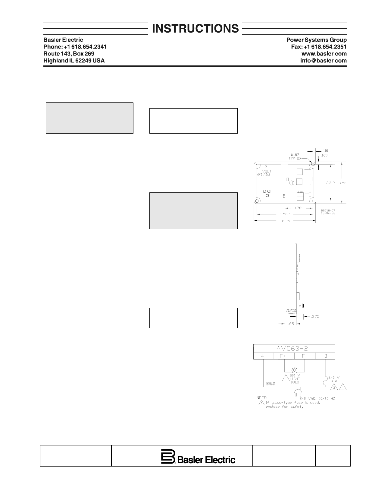
1. Connect the test setup as shown in the
figure titled
apply power. Ensure that the light bulb is
rated for 240 V and is less than 100 W.
Operational Test
.
NOTE
NOTE
. Do not
2. Adjust the regulator VOLT ADJ to
maximum CW.
3. Apply 240 V, 50/60 Hz power to the
regulator. The light bulb should illuminate.
4. Slowly adjust the regulator VOLT ADJ
control CCW. At the regulation point, the
light bulb should extinguish.
The following notes apply to the
interconnection diagrams:
1. Item not supplied by Basler Electric.
2. Select fuses with high interrupting
capacity.
Outline Diagram (Top View)
Outline Diagram (Side View)
Operational Test Connections
Publication
9318300990
Revision
B
First Printing: 01/98
Revised: 10/06
Copyright
2006
Page 2
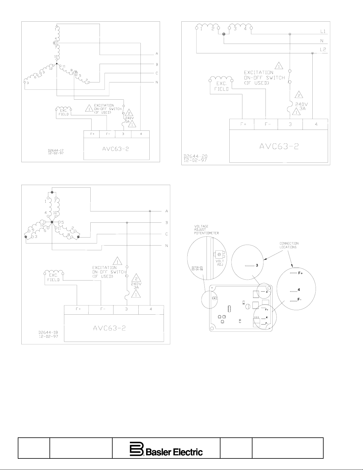
Interconnection Diagram, 277/480 V Nominal, 3-Phase, 4-Wire,
Wye Connection
Interconnection Diagram, 120/240 V Nominal, 1-Phase, 3-Wire
Interconnection Diagram, 120/208 V Nominal, 3-Phase, 4-Wire,
Wye Connection
Page 2 First Printing: 01/98
Revised: 10/06
Potentiometer and Connector Locations
Revision
B
Publication
9318300990
 Loading...