

Page 1
s
www.basler.com
+1 618.654.2341 (USA)
info@basler.com
Model
Product
AVC63-12 and AVC125-10
Voltage Regulator
INTRODUCTION
The AVC63-12 and AVC125-10 regulate the level of excitation supplied to the field of a conventional, brushless,
synchronous generator.
Regulation is achieved by sensing the generator output voltage, converting it to a dc signal, and comparing the
signal to a reference voltage. An error signal is developed and used to control the dc field power in order to
maintain a constant generator output.
Each regulator includes frequency compensation with selectable slope, inverse-time overexcitation shutdown,
buildup circuitry, single-phase or three-phase voltage sensing, single-phase or three-phase shunt or permanent
magnet generator (PMG) power input, parallel droop compensation, and an accessory input. The accessory input
provides compatibility with devices such as var/power factor controllers or excitation limiters.
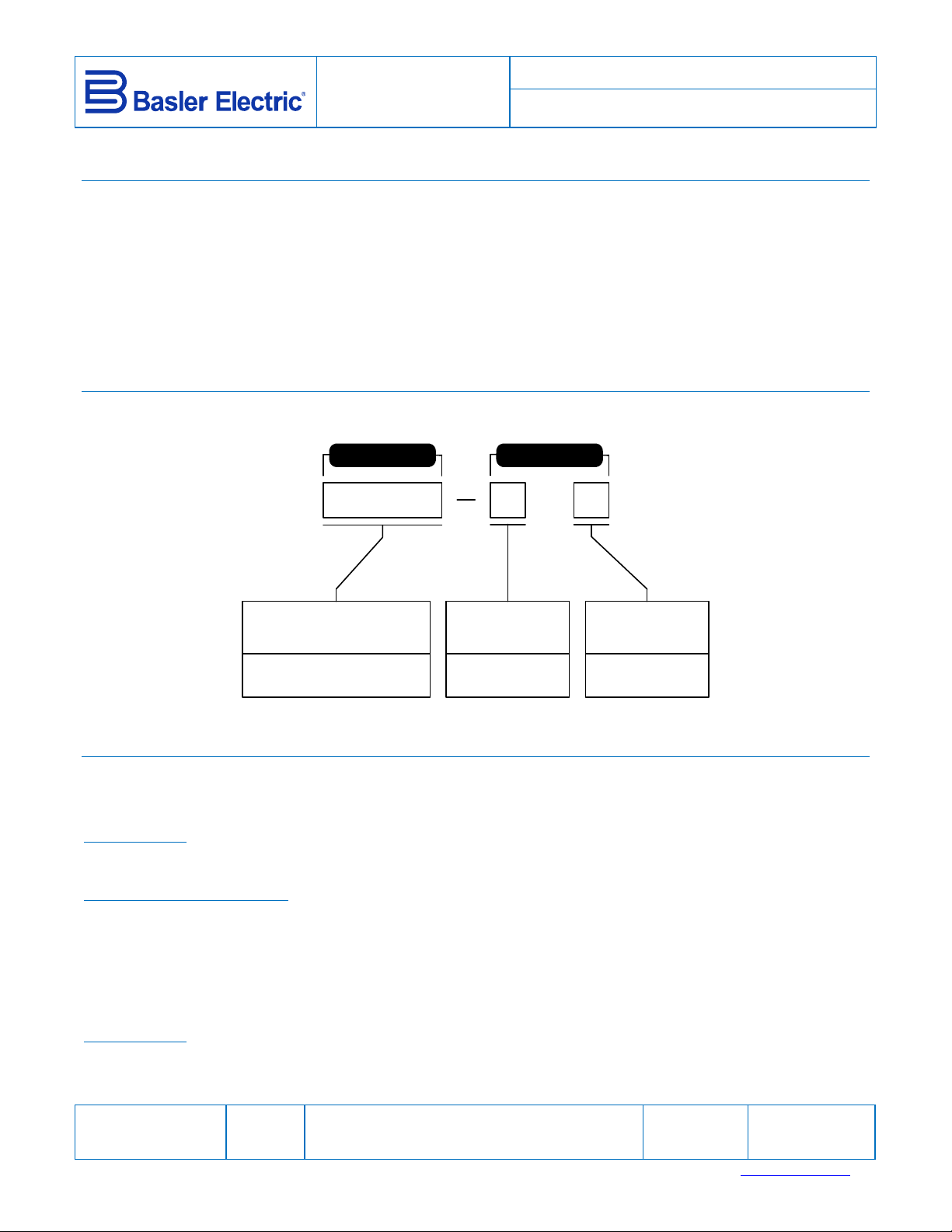
MODEL NUMBER AND STYLE NUMBER
Voltage regulator electrical characteristics are defined by a model number and style number. Model and style
number selections are illustrated in Figure 1.
MODEL NUMBER STYLE NUMBER
P0077-52
Maximum
Continuous Output
AVC63-12) 63 Vdc, 12 Adc
AVC125-10) 125 Vdc, 10 Adc
Figure 1. Style Chart
Sensing
Voltage
A) 100/120 Vac
B) 200/240 Vac
SPECIFICATIONS
Power Input
Configuration: 1-phase or 3-phase
Frequency: 50 to 400 Hz
Voltage Range
AVC63-12: 90 to 153 Vac
AVC125-10: 180 to 264 Vac
Maximum Continuous Burden
AVC63-12: 1,092 VA
AVC125-10: 1,750 VA
See Options for Inrush Current Reduction Module information.
Sensing Input
Configuration: 1-phase or 3-phase
Burden: <1 VA per phase
Voltage Range
Option A: 90 to 139 Vac
Option B: 180 to 264 Vac
Sensing
Frequency
1) 50/60 Hz
2) 400 Hz
Publication
9337200991
For terms of service relating to this product and software, see the Commercial Terms of Products and Servicesdocument available at www.basler.com/terms.
Revision
J
Instruction
Date
01/15
Copyright
2015
Page 2
s
Nominal Frequency
Option 1: 50 or 60 Hz
Option 2: 400 Hz
(See Table 2 for style/option information.)
Accessory Input
Voltage Range: 3 Vdc
Power Output
Maximum Continuous Output
AVC63-12: 12 Adc at 63 Vdc
AVC125-10: 10 Adc at 125 Vdc
10 Second Forcing Output
AVC63-12: 24 Adc at 125 Vdc
AVC125-10: 20 Adc at 250 Vdc
Minimum Field Resistance
AVC63-12: 5.25
AVC125-10: 12.5
Regulation Accuracy
0.5% of voltage setpoint, average response
Voltage Drift
0.5% variation for a 40C (104F) change
Response Time
<4 ms
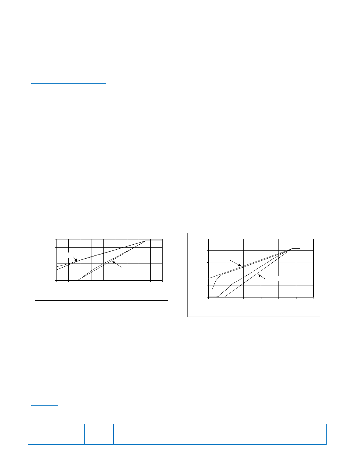
Frequency Compensation
One or two jumper-selectable V/Hz curves with knee frequency adjustable from 45 to 65 Hz (50/60 Hz units) or
300 to 430 Hz (400 Hz units). Figure 2 illustrates the 60 Hz sensing model and Figure 3 illustrates the 400 Hz
sensing model.
250
200
Ideal 1 PU/Hz
Ideal 2 PU/Hz
0
20 25 30 35 40 45 50 55 60 65
Frequency In Hertz
Figure 2. 60 Hz Sensing Model
Terminal Voltage
150
100
50
250
200
150
100
Terminal Voltage in Volts
Ideal 1 P U/Hz
Ideal 2 PU/Hz
50
0
150 200 250 300 350 400 450
Frequency i n Her t z
Figure 3. 400 Hz Sensing Model
EMI Suppression
Internal filter. (See CE Conformity)
Voltage Buildup
Automatic voltage buildup occurs from residual generator voltage as low as 6 Vac (AVC63-12) or 12 Vac
(AVC125-10).
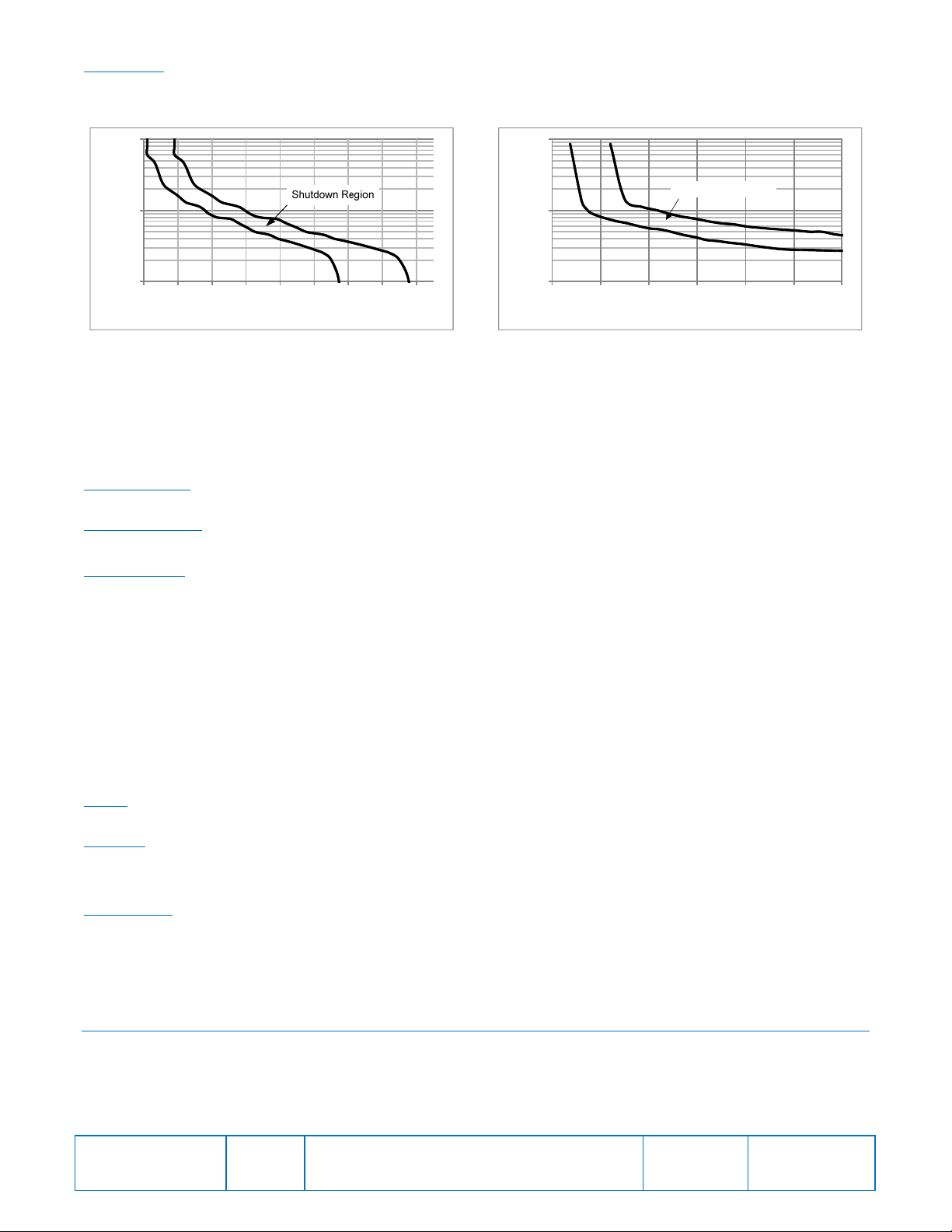
Overexcitation Shutdown
Overexcitation shutdown protection reduces the output voltage to zero in the times shown below for the listed
voltages. Other voltages and times are based on the inverse time characteristic curves of Figures 4 and 5
AVC63-12
125 Vdc, 10% in approximately 10 s
210 Vdc, 10% in approximately 1 s or less
Publication
9337200991
Revision
J
Instruction
Date
01/15
Page
2 of 10
Page 3
s
AVC125-10
250 Vdc, 10% in approximately 10 s
360 Vdc, 10% in approximately 4 s or less
100
10
Time inSeconds
1
70 90 110 130 150 170 190 210 230
DCOutputVoltage
100
Shutdown Region
10
Time inSeconds
1
240 260 280 300 320 340 360
DCOutputVoltage
Figure 4. AVC63-12 Overexcitation
Shutdown Characteristics
Figure 5. AVC125-10 Overexcitation
Shutdown Characteristics
Droop/Line Drop Compensation
<10 VA adjustable from 0 to 10% of rated input current at 0.8 power factor. (LDC compensates only for voltage
drop due to line reactance and reactive components of the load current.)
Agency Approvals
UL Recognition
UL 6200, File E97035
CSA Certification
Standard CAN/CSA-C22.2 No. 14-95, File LR 23131
CE Conformity
Radiated Emissions: EN50081-2
Conducted Emissions: EN50081-2 (EN55011, Class A)
Conducted Emissions: EN50081-2 (EN55011, Class A)
ESD Immunity: EN50082-2 (4 kV contact, 8 kV air)
EFT Immunity: EN50082-2 (2 kV coupling clamp)
Magnetic Immunity: EN50082-2 (30 Arms, 50 Hz)
Safety: EN61010-1
Radiated Immunity
Electric Field: EN61000-4-3 (10 V/m)
Conducted: EN61000-4-6 (10 Vrms)
Type Tests
Shock
Withstands 20 G in each of 3 mutually perpendicular planes.
Vibration
Withstands 4.5 G at 18 to 2,000 Hz
Physical
Temperature
Operating: –40 to 70C (–40 to 158F)
Storage: –40 to 70C (–40 to 158F)
Max. Humidity: 95%, non-condensing
Weight: 1.1 kg (2.5 lb)
MOUNTING
Regulators are contained in an encapsulated plastic case and may be mounted in any convenient position. A
regulator may be mounted directly on a genset using UNC ¼-20 or equivalent hardware. Hardware selection
should be based on any expected shipping/transportation and operating conditions. The torque applied to the
mounting hardware should not exceed 65 in-lb (7.34 Nm). See Figure 6 for regulator dimensions.
Publication
9337200991
Revision
J
Instruction
Date
01/15
Page
3 of 10
Page 4

s
Figure 6. Mounting Dimensions
CONNECTIONS
Before connecting the voltage regulator into your system, review the connection diagrams of Figures 7 and 8 and
the terminal descriptions listed in Table 1.
Publication
9337200991
Revision
J
Instruction
Date
01/15
Page
4 of 10
Page 5

s
Figure 7. Typical Connections
Publication
9337200991
Revision
J
Instruction
Date
01/15
Page
5 of 10
Page 6

s
p
)
g
GEN 1
CT
52
1
6
AVC
5 or 5A
6
AVC
5 or 5A
GEN 2
6
AVC
5 or 5A
GEN 3
1
The secondary winding of a sensing transformer must be grounded as closely to
0.1
0.1
0.1
52b
52b
52b
1
CCC
ENABLE
2
CT
3
CT
CONTACT
52
52
1
2
3
LOAD
03-07-12
P0009-26.vsd
the transformer as practical. When interconnecting more than one transformer,
ensure that the secondary winding of only one transformer is grounded.
Figure 8. Connections for Cross-Current Compensation
Table 1. Terminal Descriptions
Term # Descri
tion
CH GND Chassis ground connection
2
3
4
Auxiliary input from SCP250 and/or EL 200 (See Fig. 7)
Internal voltage adjust: connect to 7. External voltage adjust: no
connection
5 1 A current transformer (CT
5a 5 A CT
6 CT common connection
6a Common connection for selectable features
Upper Terminal Strip
7
Internal voltage adjust: connect to 4. External voltage adjust:
connect to 6a
8 Connect to 6a to select 1 V/Hz underfrequency slope
9 Connect to 6a to select 3-phase sensin
Term # Description
20 C-phase sensing input
22 A-phase sensing input
24 B-phase sensing input
26 1- or 3-phase power input
28 3-phase power input
30 1- or 3-phase power input
Lower Term. Strip
F1 Field + connection
F2 Field – connection
The secondary winding of a sensing transformer must be grounded as closely to the
transformer as practical. When interconnecting more than one transformer, ensure that
the secondary winding of only one transformer is grounded.
Publication
9337200991
Revision
J
Instruction
Date
01/15
Page
6 of 10
Page 7

s
ADJUSTMENTS
AVC63-12 and AVC125-10 adjustments are described in the following paragraphs.
Field Flashing
When the regulator is operated with the generator for the first time, the residual magnetism may not be of
sufficient magnitude or the correct polarity. If the generator residual voltage is less than 6 Vac for the AVC63-12
or 12 Vac for the AVC125-10 at terminals 26, 28 and/or 30, shut down the prime mover and proceed with the
following steps.
Caution
Do not flash the field when the generator is in motion. Regulator damage may
result.
1. With the prime mover at rest, apply an ungrounded dc source of not more than 24 Vdc to terminals F1 (+) and
F2 (–) in series with a limiting resistor. Use 1 of resistance for each volt applied. The power source should
have a rating of at least 1 W/.
EXAMPLE: If using a 24 Vdc source, use a 24 , 24 W resistor.
2. Allow the field to be flashed for approximately 10 seconds before removing the dc source.
3. If voltage buildup does not occur after performing steps 1 and 2, verify the polarity of the dc source and repeat
steps 1 and 2.
Frequency Rolloff (UF KNEE)
The underfrequency knee (rolloff) is typically set below the nominal system frequency. When the generator speed
falls below the knee setpoint of the regulator, generator voltage is reduced proportionally to the speed of the
machine. To adjust the underfrequency knee, perform the following steps.
1. Adjust the generator frequency at the nominal level (50, 60, or 400 Hz).
2. Adjust the UF KNEE control counter-clockwise.
3. Adjust the VLT ADJ control for nominal generator voltage.
4. Adjust the UF KNEE control clockwise until the voltage begins to decrease.
5. Adjust the UF KNEE counter-clockwise until the voltage just returns to the value set in step 3.
The underfrequency knee is now set just below the nominal operating frequency. Further rotation in the counterclockwise direction will lower the knee frequency setpoint at which underfrequency compensation just begins.
Connecting a jumper from terminal 8 to 6a will provide an underfrequency slope of 1 PU V/Hz. No connection to
terminal 8 will result in an underfrequency slope of 2 PU V/Hz. The slope can also be selected on the 400 Hz
models. However, the actual V/Hz curve is approximately 1 PU or 2 PU, depending if terminal 8 is jumpered to 6a.
Stability (STB)
An oscilloscope or other voltage recording device should be used in an optimal stability setting is desired. Adjust
the stability setting with the generator at no load.
Clockwise rotation of the STB control will slow response time. Counter-clockwise rotation will speed response
time. If rotated too far counter-clockwise, the generator voltage may oscillate (hunt).
To obtain good response, rotate the STB control counter-clockwise until the system just begins to oscillate. Then,
rotate the control clockwise just past the point where oscillation occurred. Apply various amounts of load to
determine proper stability performance.
Voltage (VLT ADJ)
Installation of a jumper across terminals 4 and 7 enables the front-panel VLT ADJ control to vary the generator
nominal voltage over the operating range.
To allow operation of an external voltage-adjust control, remove the jumper between terminals 4 and 7 and
connect a 10 k, external potentiometer across terminals 6a and 7. The front-panel VLT ADJ control should be
set fully clockwise for proper operation of the external adjustment. Note that as the external potentiometer
resistance increases, generator voltage also increases.
Publication
9337200991
Revision
J
Instruction
Date
01/15
Page
7 of 10
Page 8

s
Factory Calibration (FAC CAL)
Caution
The FAC CAL control is intended for use during factory calibration only. The
following procedure can be used if the factory calibration has been disturbed.
1. With the regulator operating on a generator, adjust the FAC CAL control fully counterclockwise and the
external voltage adjust control fully clockwise.
2. Adjust the FAC CAL control clockwise until the generator voltage reaches the desired maximum voltage
setting. The regulator is calibrated and the FAC CAL control can be sealed.
Parallel Droop Compensation
Variable parallel droop compensation levels can be obtained by adjusting the DRP control. Clockwise rotation
increases the amount of droop for a given condition.
Line Drop Compensation
When the sensing input CT connections are reversed to provide line drop compensation, the droop adjustment
becomes the line drop compensation adjustment.
STARTUP
Startup and troubleshooting procedures for the AVC63-12 and AVC125-10 are listed in the following procedure.
Symptoms of startup problems stemming from improper regulator adjustments and certain generator system
problems that resemble faulty regulation are listed with possible solutions. Simplifying the system by eliminating
components, such as remote adjustment potentiometers and other nonessential items, can be helpful in the
troubleshooting process. Adjustments, options, and an operational test are included in the paragraphs following
the procedure.
1. Ensure that the regulator has been installed in accordance with the Installation and Connections paragraphs
before proceeding with system startup.
2. Start the prime mover and bring it up to rated speed.
If the voltage does not build up:
a. Flash the field.
b. Remove power for one minute to reset the overexcitation circuit.
3. Slowly adjust the VOLT potentiometer or external, voltage adjust rheostat until the voltage reaches nominal.
If the voltage will not build up to rated:
Check the generator output for a shorted or excessive load.
4. Apply and remove the generator load to check stability.
If the generator response is too slow or is hunting (oscillating):
a. Check the generator output for a shorted or excessive load. Adjust the STB potentiometer with no load
applied.
b. Check stability of the governor.
5. Check regulation under normal operating conditions.
If the regulation is poor:
a. Check that the prime mover is up to rated speed.
b. Check that the voltmeter is connected at the same point as the regulator sensing.
c. Use an average-sensing voltmeter (not an rms-sensing voltmeter).
6. Reduce the generator frequency. The generator output should decrease from this point.
If the generator output voltage does not decrease at the desired frequency:
a. Check that all wiring is in accordance with the connection diagrams provided in this instruction sheet.
b. Adjust the UF KNEE control.
Publication
9337200991
Revision
J
Instruction
Date
01/15
Page
8 of 10
Page 9

s
OPTIONS
The AVC63-12 and AVC125-10 may be equipped with the following options to enhance operation.
Remote Voltage Adjust
Connect a 10 k, 2 W potentiometer across terminals 6a and 7, remove the jumper from terminals 4 and 7, and
adjust the front panel VLT ADJ control fully clockwise to enable remote adjustment of the voltage setpoint.
Inrush Current Reduction Module
A Basler ICRM-15 is required when energizing the AVC63-12 or AVC125-10 from a source that is already at the
regulator input power rating. The ICRM-15 minimizes the amount of inrush current that could be seen when power
is applied.
Excitation Disable
This option disables excitation by removing power from the regulator. A switch removing voltage from terminals
26, 28 and/or 30 will remove regulator power.
Excitation Limiter
The Basler EL 200 provides an initial, fast-acting limit of the field current at a user-defined level. Once the field
current has changed to the selected level, the EL 200 provides a signal to the regulator to change the excitation
level.
Var/Power Factor Control
This option enables the AVC63-12 and AVC125-10 to regulate the var and power factor while the generator is
connected to an infinite or utility bus. The Basler SCP 250 supplies a dc signal into terminals 2 and 3 of the
regulator to correct for vars or power factor. Figure 9 illustrates regulator and SCP 250 interconnection.
Partof
AVC63‐12
or
AVC125‐10
AVC units may be connected to either the
EL 200 or the SCP 250 using the
terminals as shown in place of this series
interconnection. See the unit instruction
manuals for more information.
When the AVC receives a positive voltage
(terminal 2 positive, terminal 3 negative)
at the Accessory input, the setpoint
decreases. A negative voltage (terminal 2
negative, terminal 3 positive) at the
Accessory input increases the setpoint.
Figure 9. Interconnection with EL 200 and SCP 250
3
2
P0009-25
L
C
A
C
Partof
EL200
Partof
SCP250
Current Boost System
With the CBS 212A option, if the generator output voltage decreases below the preset operating point due to a
short or large motor starting, the CBS 212A provides full current boost to the generator exciter until the voltage
returns to a level just above the operating point.
Manual Voltage Control
The Basler MVC-112 provides a method for manually controlling the generator output during generator startup
and commissioning or in the unlikely event of a regulator failure. Model MVC-112 is suitable for use with either the
AVC63-12 or AVC125-10 voltage regulator.
OPERATIONAL TEST
This test verifies AVC63-12 and AVC125-10 operation. Table 2 lists each regulator model and the corresponding
test voltage and frequency.
To test regulator operation, perform the following steps.
1. Connect the regulator according to Figure 10 and apply the appropriate voltages.
2. Adjust the VLT ADJ control fully counter-clockwise. Observe that the lamp is off.
Publication
9337200991
Revision
J
Instruction
Date
01/15
Page
9 of 10
Page 10

s
3. Adjust the VLT ADJ control clockwise.
p
g
Observe that the lamp turns on.
4. Adjust the VLT ADJ control until the lamp just turns off.
Table 2. Test Voltage and Frequency
ut
In
Sensin
Model
AVC63-12A1 120 120 50/60
AVC63-12A2 120 120 400
AVC63-12B1 120 240 50/60
AVC63-12B2 120 240 400
AVC125-10A1 240 120 50/60
AVC125-10A2 240 120 400
AVC125-10B1 240 240 50/60
AVC125-10B2 240 240 400
Power
Vac Hz
Regulator operation is satisfactory if the above results are obtained. However, stability must be tested with the
generator and regulator in operation.
100 W
Lamp
Sensing
Voltage
10
ohms
Input
Power
20
ohms
1
26 30 20
F1 F2
28
22
24
AVC63-12 or AVC125-10
CH
23
GND
03-24-06
D2590-33
A wire-wound resistor with a minimum
1
power rating of 15 W should be used.
MAINTENANCE
A periodic inspection of the regulator should be made to ensure that it is clean and free from accumulations of
dust and moisture. Ensure that all connections are clean and tight.
4
5
Figure 10. Test Setup
6
6a
7
9
85a
TROUBLESHOOTING
In case of regulator failure or defective operation, simplifying the system by eliminating components such as
remote adjust potentiometers and other non-essential items can be helpful in the troubleshooting process.
Publication
9337200991
Revision
J
Instruction
Date
01/15
Page
10 of 10
 Loading...