

Page 1
Models P1B65Q and P2B65Q
Pixel-Counting Sensors
Instruction Manual
WARNING . . . Not To Be Used for Personnel Protection
Never use these products as sensing devices for personnel protection. Doing
so could lead to serious injury or death.
These sensors do NOT include the self-checking redundant circuitry necessary to allow
their use in personnel safety applications. A sensor failure or malfunction can cause
either an energized or de-energized sensor output condition. Consult your current
Banner Safety Products catalog for safety products which meet OSHA, ANSI and IEC
standards for personnel protection.
P/N 56910COA 08/03
56910 (presplus sensor)C0A 8/16/03 11:33 PM Page 1
Page 2

56910 (presplus sensor)C0A 8/16/03 11:33 PM Page 2
Page 3

P/N 56910COA 1
Contents
Banner Engineering Corp. • Minneapolis, MN U.S.A.
www.bannerengineering.com • Tel: 763.544.3164
OVERVIEW
Product Description . . . . . . . . . . . . . . . . . . . . . . . . . . . . . . . . . . . . . . . . . . . . . . . . . 2
Application Examples. . . . . . . . . . . . . . . . . . . . . . . . . . . . . . . . . . . . . . . . . . . . . . . . 2
SYSTEM COMPONENTS
Controller . . . . . . . . . . . . . . . . . . . . . . . . . . . . . . . . . . . . . . . . . . . . . . . . . . . . . . . . . 4
Cables. . . . . . . . . . . . . . . . . . . . . . . . . . . . . . . . . . . . . . . . . . . . . . . . . . . . . . . . . . . . 4
Lenses . . . . . . . . . . . . . . . . . . . . . . . . . . . . . . . . . . . . . . . . . . . . . . . . . . . . . . . . . . . 4
Mounting Brackets . . . . . . . . . . . . . . . . . . . . . . . . . . . . . . . . . . . . . . . . . . . . . . . . . . 4
Light Sources. . . . . . . . . . . . . . . . . . . . . . . . . . . . . . . . . . . . . . . . . . . . . . . . . . . . . . 4
Kits . . . . . . . . . . . . . . . . . . . . . . . . . . . . . . . . . . . . . . . . . . . . . . . . . . . . . . . . . . . . . . 4
SENSOR SETUP
Changing Lens Filters . . . . . . . . . . . . . . . . . . . . . . . . . . . . . . . . . . . . . . . . . . . . . . . 6
Mounting the Lens . . . . . . . . . . . . . . . . . . . . . . . . . . . . . . . . . . . . . . . . . . . . . . . . . 6
Appropriate Sensing Environment . . . . . . . . . . . . . . . . . . . . . . . . . . . . . . . . . . . . . 6
Mounting the Sensor . . . . . . . . . . . . . . . . . . . . . . . . . . . . . . . . . . . . . . . . . . . . . . . . 7
Connecting Cables . . . . . . . . . . . . . . . . . . . . . . . . . . . . . . . . . . . . . . . . . . . . . . . . . . 8
LIGHTING OPTIONS
Lighting Techniques. . . . . . . . . . . . . . . . . . . . . . . . . . . . . . . . . . . . . . . . . . . . . . . . 10
SENSOR OPERATION
Status Indicators . . . . . . . . . . . . . . . . . . . . . . . . . . . . . . . . . . . . . . . . . . . . . . . . . . 16
Programming and Monitoring the Sensor. . . . . . . . . . . . . . . . . . . . . . . . . . . . . . . 17
Controller Menu . . . . . . . . . . . . . . . . . . . . . . . . . . . . . . . . . . . . . . . . . . . . . . . . . . . 18
MAINTENANCE
Cleaning the System . . . . . . . . . . . . . . . . . . . . . . . . . . . . . . . . . . . . . . . . . . . . . . . 19
REFERENCE
Specifications. . . . . . . . . . . . . . . . . . . . . . . . . . . . . . . . . . . . . . . . . . . . . . . . . . . . . 20
Dimensions . . . . . . . . . . . . . . . . . . . . . . . . . . . . . . . . . . . . . . . . . . . . . . . . . . . . . . 22
Appendix A: Selecting a Lens. . . . . . . . . . . . . . . . . . . . . . . . . . . . . . . . . . . . . . . . . 25
Appendix B: Component Lists . . . . . . . . . . . . . . . . . . . . . . . . . . . . . . . . . . . . . . . . 30
Glossary . . . . . . . . . . . . . . . . . . . . . . . . . . . . . . . . . . . . . . . . . . . . . . . . . . . . . . . . . 32
56910 (presplus sensor)C0A 8/16/03 11:33 PM Page 1
Page 4
Product Description
2 P/N 56910COA
Overview
PresencePLUS™ Pixel-Counting Sensor Models P1B65Q/P2B65Q* house a 512 x
384 CMOS pixel array and a programmable microprocessor. Each sensor captures a
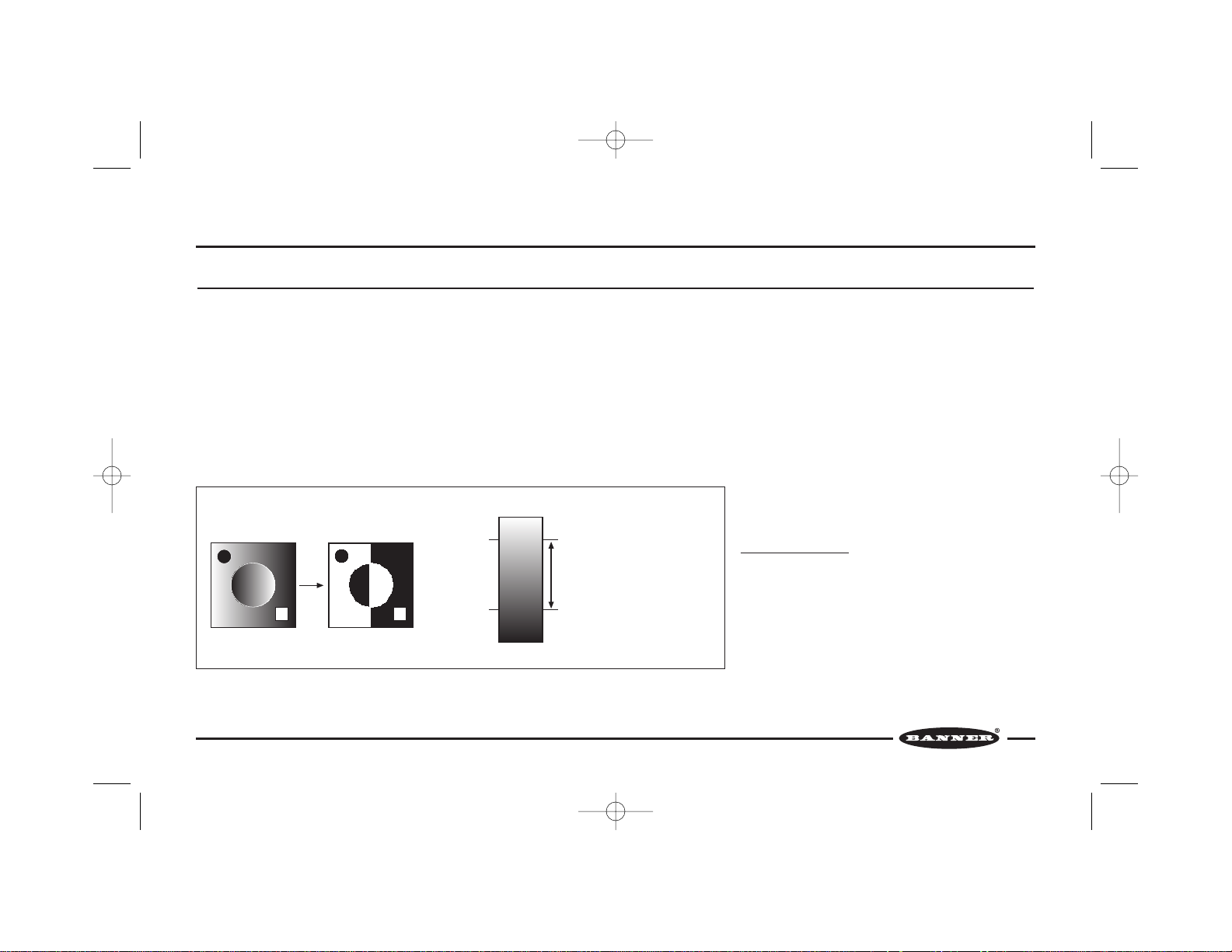
gray-scale image, converts the image to binary format based on adjustable grayscale thresholds, counts the number of white or black pixels, and judges the image
as “PASS” or “FAIL” by comparing the counts to reference counts.
An image is captured in response to a signal from a user-supplied trigger input
device. The trigger device is typically a presence-sensing device such as a
photoelectric sensor that delivers an input signal coincident with the passage of the
leading or trailing edge of an object to be inspected.
The binary value of each pixel is determined by two adjustable gray-scale
thresholds. The lower threshold defines the division between “light” and “dark”. The
sensor counts all light pixels as white and all dark pixels as black. The upper
threshold defines the limit above which pixels will be ignored. The sensor may be
set to count either black or white pixels and to accept a percentage above or below
reference pixel counts.
The PresencePLUS™ sensor is configured for trigger input, signal output, lighting
options and other sensor parameters using either the remote controller (Model
PRC1) and/or the PresencePLUS PC software, depending on sensor model. While
the sensor is in operation, the controller or PC may be used to view captured
images and monitor sensor performance.
For more information about programming and operating the
sensor, see page 17.
Application Examples
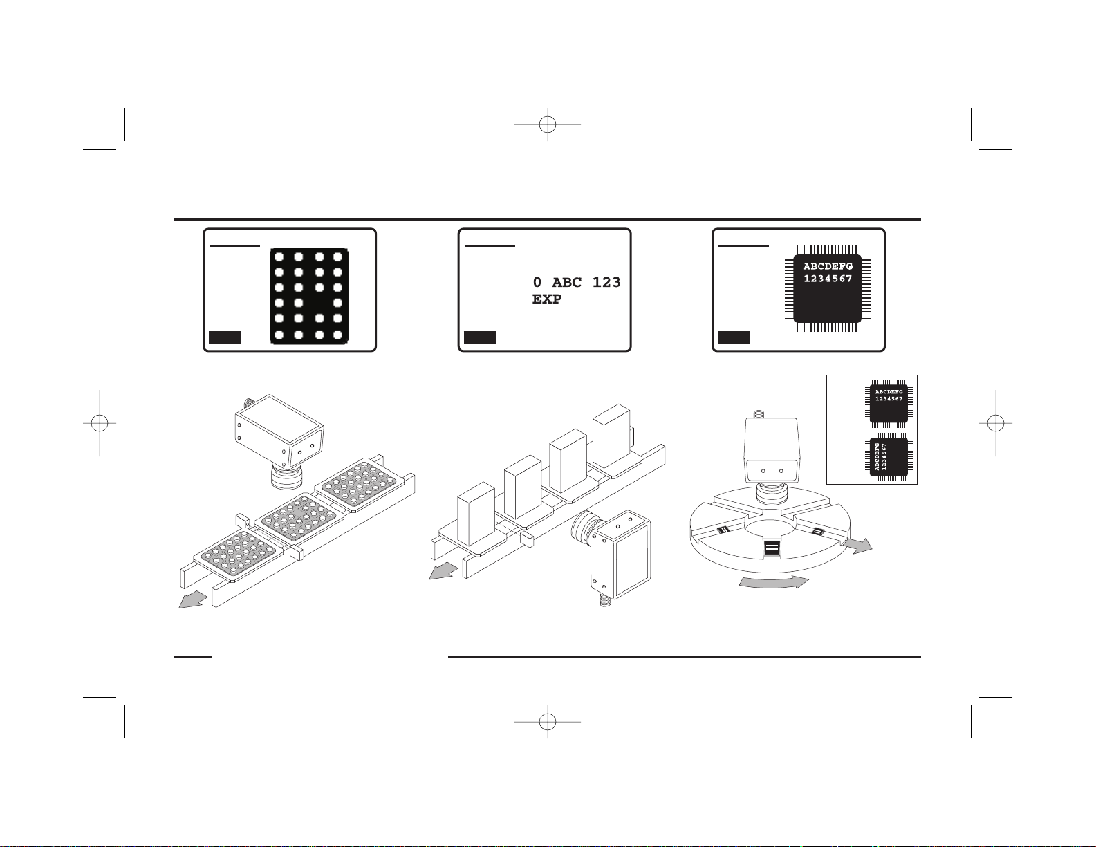
The PresencePLUS sensor is a solution to many inspection
applications where a defect can occur anywhere within the
sensor’s field of view, and where a configuration of multiple
discrete sensors is either cost-prohibitive or mechanically
impractical. The inspection examples shown on the next
page illustrate a few application possibilities.
Gray-scale images are converted to black and white by comparing the value of each pixel to adjustable gray-scale
thresholds
*Model P2B65Q available fall 2000.
56910 (presplus sensor)C0A 8/16/03 11:33 PM Page 2
Gray-Scale Binary
Threshold
Threshold
255 (White)
Upper
Lower
0 (Black)
Ignores pixels with a value above
this threshold.
Counts pixels with a value between
these thresholds as white.
Counts pixels with a value below
this threshold as black.
Page 5
P/N 56910COA 3
Overview
Banner Engineering Corp. • Minneapolis, MN U.S.A.
www.bannerengineering.com • Tel: 763.544.3164
Missing Date/Lot Code Inspection and
Print Quality Control
Controller LCD DisplayController LCD DisplayController LCD Display
0 ABC 123
EXP 7/02
0 ABC 123
EXP 7/02
0 A
B
C 123
E
X
P
0 A
B
C
1
2
3
E
XP 7/
0
2
Eject Wrong
Orientation
Missing Tablet Detection IC Orientation Inspection
SETUP
Focus
101
LIGHTEN
0
DARKEN
DONE
SETUP
Focus
84
LIGHTEN
0
DARKEN
DONE
SETUP
Focus
98
LIGHTEN
0
DARKEN
DONE
56910 (presplus sensor)C0A 8/16/03 11:33 PM Page 3
Correct
Incorrect
Page 6
4 P/N 56910COA
System Components
PresencePLUS Sensor models P1B65Q/P2B65Q require several other components to create a working system: controller (hand-held controller or PC), cable, lens,
mounting bracket (if needed), light source, trigger device (user-supplied), and power supply (user-supplied). For more information about system components, see page 30
or visit Banner’s web site at www.bannerengineering.com.
Controller/PC
The PresencePLUS model P1B65Q sensor can be configured, programmed, and
monitored by the PresencePLUS controller (model PRC1), and the model P2B65Q
sensor by the PresencePLUS controller or by the PresencePLUS PC software.
Cables
Banner offers quick-disconnect cables in multiple lengths, with straight or rightangle connectors.
Lenses
Banner offers several C-mount lens choices; or the lens may be user-supplied. For
information about how to select a lens, see pages 25-29.
Mounting Brackets
Banner offers several mounting options. For bracket information, see pages 23-24
and 30.
Light Sources
Banner offers a number of light sources. The light source may be user-supplied. For
more information, see pages 10-15 and 30.
Kits
Banner PresencePLUS kits include a sensor, cable, bracket, and light source, and
may include a controller. For an example of kit options, see page 31.
56910 (presplus sensor)C0A 8/16/03 11:33 PM Page 4
Page 7
P/N 56910COA 5
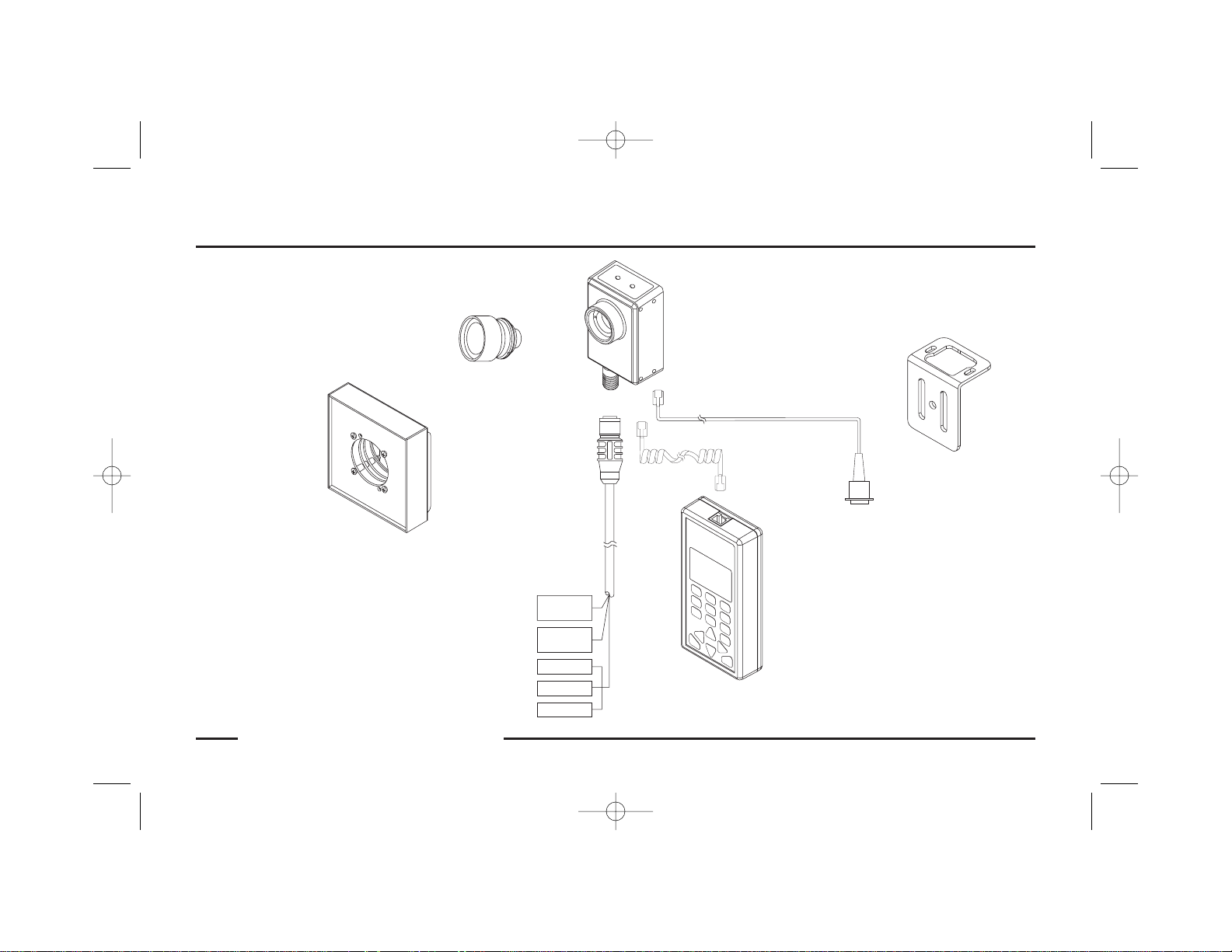
Example System
Banner Engineering Corp. • Minneapolis, MN U.S.A.
www.bannerengineering.com • Tel: 763.544.3164
PresencePLUS Sensor
Model P1B65Q/P2B65Q
PresencePLUS Controller
Model PRC1
Mounting Bracket
Quick-Disconnect
Cable
C-Mount
Lens
Light Source
or Coiled Cord
(supplied with
PRC1)
Straight Cord for PC Controller
(P2B65Q only; sold separately)
To User-supplied
PC Controller
56910 (presplus sensor)C0A 8/16/03 11:33 PM Page 5
AIL
F
ASS
P
T
L
AU
F
Y
WER
READ
PO
Tr igger
Device
24V dc
Supply
Output 1
Output 2
Output 3
Page 8
6 P/N 56910COA
Sensor Setup
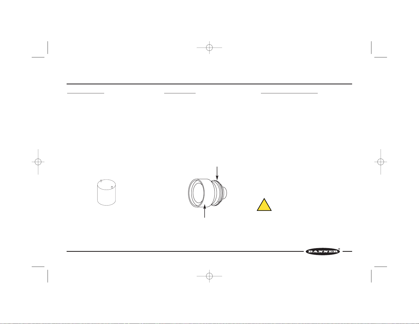
Changing Lens Filters
The lens filter is located behind the lens, held in place
with a retainer ring.
To add or remove a filter, use the tool supplied with
the sensor to remove and replace the retainer ring.
A red filter is pre-installed in each sensor for use with
red light sources. Remove this red filter if using a light
source other than red.
NOTE: When using more than one filter, the order of
the filters’ placement will not affect performance.
Mounting the Lens
Remove the protective cover from the sensor. Remove
the two protective covers from the lens. Install the
lens onto the sensor by gripping the silver lens base
and turning clockwise (RH thread).
NOTE: Do not install by gripping and turning the
plastic lens shroud. Also, see CAUTION, below.
After focusing the lens, use the supplied Allen wrench
to lock the lens by clockwise rotation (RH thread),
finger tight, in the three set screws on the base of the
lens.
Appropriate Sensing Environment
The sensing location must meet the following criteria
for reliable operation:
• Stable ambient temperature: 0 to 50°C (+32 to
122°F)
• Ambient relative humidity: 35 to 90%,
non-condensing
•Stable ambient lighting: no large, quick changes in
light level; no direct or reflected sunlight
•No significant vibration or mechanical shock
• No liquid splash
• No contact with corrosive or volatile materials or
atmosphere
•Minimal dust or dirt
Retainer Ring Tool
Grip Silver lens base
Do not grip plastic lens shroud
CAUTION . . .
Sensor contains ESD-sensitive components.
Use proper ESD (electrostatic discharge) precautions to avoid potential damage to sensor.
56910 (presplus sensor)C0A 8/16/03 11:33 PM Page 6
!
Page 9
P/N 56910COA 7
Sensor Setup
Banner Engineering Corp. • Minneapolis, MN U.S.A.
www.bannerengineering.com • Tel: 763.544.3164
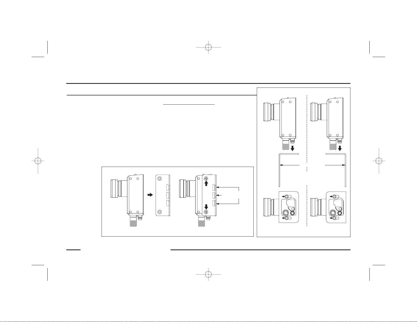
Mounting the Sensor
The sensor has ten M4 x 0.7 tapped holes: four on
each side and two on the base. The sensor is supplied
with four M4 sockethead cap screws, washers, and
lockwashers, and a 3 mm Allen wrench.
The sensor may be secured to a Banner-supplied
mounting bracket, or to any flat surface up to 2.0 mm
(0.08") thick.
For dimensional details of the sensor and brackets,
see pages 22-24.
Securing to Mounting Brackets
Two mounting bracket choices include:
• Column-mounting bracket SMBPCM
• Base-mounting bracket SMBPBM
Secure the sensor to the column-mounting bracket
with the four M4 Phillips flathead screws supplied
with the bracket (two on each side).
Secure the sensor to the base-mounting bracket with
two of the M4 sockethead cap screws, washers, and
lockwashers supplied with the sensor.
Column-Mounting Bracket SMBPCM
Base-Mounting Bracket SMBPBM
56910 (presplus sensor)C0A 8/16/03 11:33 PM Page 7
Sensor
Bracket
M6x1
1/4"-20
Tread
Thread
Secure with four M4 Phillips
flathead screws supplied with
bracket (two on each side)
Sensor
Bracket
M4 sockethead cap screws,
washers, and lockwashers
(Either Direction)
Secure with two
supplied with sensor
Page 10
8 P/N 56910COA
Sensor Setup
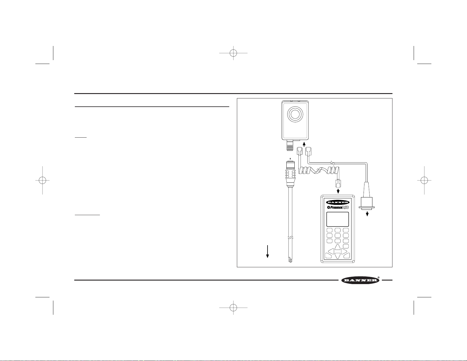
Connecting Cables
Before connecting cables, be sure the power supply is OFF. See CAUTION on page
6. For complete sensor specifications and hookup diagrams, see pages 20-21.
Power
The power source is user-supplied.
Alone, the sensor requires 22 to 26V dc; with a maximum current of 250 mA
(exclusive of loads and the current required by the PRC1 controller and optional
attached light source).
Using the PRC1 controller, the maximum current is 450 mA. Using the LEDR140
light source, the maximum current is 550 mA. Using both, the maximum current is
750 mA.
Connect the Brown wire of the sensor cable (MQDC-6 Series) to +V and the Blue
wire to dc common. Attach the connector end of the cable to the sensor.
Controller/PC
PRC1: A coiled cord with modular plugs is supplied with the PRC1 controller. Insert
one plug into the controller and the other plug into the sensor. Be sure the plugs
click into place.
PC: A straight cord with a modular plug on one end and a 9-pin connector on the
other is sold for use with the PresencePLUS P2B65Q sensor and a PC. Insert the
modular plug into the sensor and the 9-pin connector into a serial port of a PC. Be
sure the plug on the sensor clicks into place.
Controller
SETUP ROI TEACH
LOAD
HELP ENTER
RUN
MAIN
RUN
P/F
RUN
JUDGE
CONFIG
MAIN
MENU
IMAGE
CNTRL
TM
P1B65Q/
P2B65Q
Straight Cord
to PC (sold separately)
to PC
or Coiled Cord
(Supplied with PRC1)
MQDC-6 Series
Cable
To Power Source,
Trigger Device, and
Output Receiver
PRC1
Controller Connection to the Sensor
56910 (presplus sensor)C0A 8/16/03 11:33 PM Page 8
Page 11

P/N 56910COA 9
Banner Engineering Corp. • Minneapolis, MN U.S.A.
www.bannerengineering.com • Tel: 763.544.3164
Sensor Setup
Trigger Input
Connect the Pink wire of the sensor cable to the user-supplied trigger device.
The default trigger input setting accepts signals from a trigger device with an NPN (current sinking) output. If the
trigger device output is PNP (current sourcing), use the PRC1 controller to reconfigure either sensor or the
PresencePLUS PC software to reconfigure the P2B65Q sensor.
Signal Output
The sensor provides three SPST solid-state contacts which may be individually programmed for either NPN
(current sinking) or PNP (current sourcing). Each output is capable of switching up to 26V dc max at
50 mA max. Outputs are protected against continuous overload or short circuit.
Note: Output loads must not be returned to any voltage greater than +V.
Configure the sensor cable output wires as follows: White = Output #1, Black = Output #2, Gray = Output #3. Use
the PRC1 controller to set output parameters for either sensor, or the PresencePLUS PC software to set P2B65Q
sensor parameters.
56910 (presplus sensor)C0A 8/16/03 11:33 PM Page 9
Page 12

10 P/N 56910COA
Lighting Options
Lighting Techniques and Sources
Proper lighting is often the determining factor between an application’s success or failure. The following options have been developed to overcome the most common
lighting obstacles.
Ring Light
A ring light is a general-purpose lighting technique. The light mounts directly to the
sensor for easy setup. The light illuminates any object directly in front of the
sensor.
Advantages: The ring light provides even illumination for small objects. It also
reduces shadows on images with protrusions. Because the light is attached to the
sensor, the light will be centered on the image.
Disadvantages: For larger objects, the corners of the image may lose illumination
intensity. This may create a “halo” of dark pixels along the outer edge of the image.
Highly reflective surfaces may reflect a circular glare pattern back to the sensor.
Ring Light
56910 (presplus sensor)C0A 8/16/03 11:33 PM Page 10
Light Source
Object
Page 13

P/N 56910COA 11
Lighting Options
Banner Engineering Corp. • Minneapolis, MN U.S.A.
www.bannerengineering.com • Tel: 763.544.3164
Backlight
For backlighting, the light is placed behind the target, facing directly into the
sensor. When the target is between the light and the sensor, it blocks the light,
creating a silhouette. The sensor may inspect the silhouette for proper size and/or
shape.
Advantages: The backlight is not affected by color or texture variations in the
target. The backlight can show the diameter of a rounded target consistently.
Through-holes in a target will be readily apparent.
Disadvantages: The backlight must be placed behind the target, which may be
physically impractical. Backlighting does not highlight changes in a target’s
surface. The light must be larger than the area of inspection.
Backlight
56910 (presplus sensor)C0A 8/16/03 11:33 PM Page 11
Object
Light Source
Page 14

12 P/N 56910COA
Lighting Options
Directional Front Light
Directional Front Light
Directional front lighting may use one or more lights to highlight specific areas of a
target. Placing light at a certain angle may highlight a specific feature of a target,
allowing the sensor to detect the presence or absence of that feature.
Advantages: The directional front light can be used to create glare and shadows
with a strong illumination source. It can highlight a specific surface angle. For
reflective surfaces, using a directional front light avoids the ring of glare caused by
a ring light.
Disadvantages: The directional front light creates glare and shadows. Surfaces
with protrusions may create a shadow over the inspection area. Highly reflective
surfaces may produce “hot spots” of glare on the image.
56910 (presplus sensor)C0A 8/16/03 11:33 PM Page 12
Light Source
Object
Page 15

P/N 56910COA 13
Lighting Options
Banner Engineering Corp. • Minneapolis, MN U.S.A.
www.bannerengineering.com • Tel: 763.544.3164
Diffused Light
Diffused Light
Diffused lighting is used when direct lighting produces too much glare and shadow.
To diffuse a light source, a diffuser is placed between the light source and the
sensing target. A diffuser may be made from frosted glass, acrylic, or any
translucent material that spreads the light evenly. For highly diffused light, a “dome
light” or “cloudy day illuminator” may be used by reflecting the light off an opaque
white hemisphere, onto the sensing target.
Advantages: Minimizes glare and shadowing; with a dome light the shadows and
glares are removed almost completely. Illuminates curved surfaces evenly.
Disadvantages: Diffusing light lowers the illumination intensity, causing the
surface features of an object to become less distinct. The dome light must be
bigger than the sensing target.
56910 (presplus sensor)C0A 8/16/03 11:33 PM Page 13
Object
Page 16

14 P/N 56910COA
Lighting Options
Low-Angle Light
Low-Angle Light
Low-angle light is projected perpendicular to the inspection direction. If a sensing
target does not break the light beam, the sensor will not receive the light and the
entire image will appear dark.
Advantages: This technique highlights surface irregularities, such as dust, small
dents, scratches and other surface defects.
Disadvantages: Low-angle lighting is effective only in small areas because light
widens as it travels away from its source, becoming less perpendicular. Low-angle
light provides “hot spots” and a high degree of shadowing.
56910 (presplus sensor)C0A 8/16/03 11:33 PM Page 14
Light
Source
Object
Page 17

P/N 56910COA 15
Lighting Options
Banner Engineering Corp. • Minneapolis, MN U.S.A.
www.bannerengineering.com • Tel: 763.544.3164
Polarized Light
Polarized Light
Polarized light is created when a polarizing filter is
placed in front of the light source and in front of
the imaging chip of the sensor. The filters must be
rotated 90° out of phase to one another to reduce
glare. Polarizing may be used in conjunction with
other lighting techniques.
Advantages: Polarizing an image removes glare
from a highly reflective surface. The filters also act
as diffusers to provide even illumination.
Disadvantages: Polarizing the light significantly
lowers illumination intensity.
56910 (presplus sensor)C0A 8/16/03 11:33 PM Page 15
Light Source
Polarizing
Filter
Shiny Object
Polarizing
Filter
Page 18

16 P/N 56910COA
Sensor Operation
Status Indicators
Two LEDs on the top of the sensor indicate the current sensor and judgment status.
Sensor Status Indicator
When this indicator is flashing yellow, the power is ON and the sensor is powering
up (initializing its parameters and executing self-diagnostics).
When this indicator is solid yellow, the power is ON, the sensor is not running and
will not process (judge) triggers. It will, however, accept setup operations from the
controller.
When this indicator is green, the power is ON and the sensor is in RUN mode and
READY to process (judge) triggers.
When this indicator is red, the power is ON and a hardware FAULT has been
detected.
Judgment Status Indicator
When this indicator is green, the judgment result of the last trigger was PASS.
When this indicator is red, the judgment result of the last trigger was FAIL.
Status Indicators
56910 (presplus sensor)C0A 8/16/03 11:33 PM Page 16
Sensor Status
(Red, Green, Yellow)
POWER
READY
FAULT
Judgment Status
(Red, Green)
PASS
FAIL
Page 19

Programming and Monitoring the Sensor
P/N 56910COA 17
Sensor Operation
Banner Engineering Corp. • Minneapolis, MN U.S.A.
www.bannerengineering.com • Tel: 763.544.3164
Either PresencePLUS sensor may be programmed and monitored using the
companion PresencePLUS PRC1 hand-held remote control microprocessor. The
PresencePLUS P2B65Q sensor also may be programmed and monitored using the
PresencePLUS PC software.
For complete sensor programming and monitoring instructions using the PRC1
controller, see the PresencePLUS PRC1 Controller Instruction Manual (P/N 57413),
supplied with each controller.
For instructions on programming and monitoring the P2B65Q sensor with the
PresencePLUS PC software, see the PresencePLUS PC software help menus or
documentation. The software and documentation is available on Banner’s web site
at www.bannerengineering.com.
Depending on the sensing application requirements, programming the sensor
involves up to three steps: SETUP, ROI, and TEACH.
In the first step, the SETUP mode is used to adjust the target object within the
sensor’s pixel array, run the auto-exposure routine, focus the sensor’s lens, and
lighten or darken the image.
In the second step, the ROI mode may be used to define a Region of Interest (ROI)
within the array for judgment or to mask an area to exclude from judgment.
In the third step, the TEACH mode is used to “teach” the sensor to recognize good
and (optionally) bad images by presenting a number of product examples. The
controller or PC uses the pixel counts from these examples to determine judgment
criteria for subsequent sensor operation. Judgment criteria may be manually
adjusted.
If the application does not require defining an ROI, masking, or teaching bad
product, the QUICK START option provides a simple one-step SETUP, TEACH, and
RUN sequence. The resulting judgment criteria may be manually adjusted.
CONFIGURE screens are used to program parameters that typically only need to be
set once. Configuration parameters include selecting the application type (to enable
the most appropriate auto-exposure settings), which pixel color to count (white or
black) and lighting options.
Up to four different sets of parameters may be saved as files from either sensor to
the controller, or multiple sets of parameters may be saved as files from the
P2B65Q to a PC using the PresencePLUS PC software. This feature allows
parameters to be downloaded to the sensor when setting up different product runs
or programming more than one sensor.
After the sensor has been programmed and configured, the controller or PC is used
to put the sensor into RUN mode. While the sensor is in operation, RUN screens
may be used to monitor PASS/FAIL and pixel count statistics, view captured
images, or adjust configuration settings and gray-scale thresholds.
56910 (presplus sensor)C0A 8/16/03 11:33 PM Page 17
Page 20

18 P/N 56910COA
Sensor Operation
Controller Menu
QUICK START
• Automatically set judgment criteria and put the sensor
into RUN mode
SETUP
• Run the auto-exposure routine
• Focus the lens
• Lighten or darken the image
ROI
•Define region of interest for judgment
•Mask area to exclude from judgment
• Adjust focus
• Adjust gray-scale thresholds
TEACH
• Set judgment criteria
• Adjust judgment criteria before operation
RUN
•View PASS and FAIL statistics
• View pixel count statistics
• Adjust judgment criteria during operation
•View images
CONFIGURE
• Set configuration parameters:
– Application type
– Pixel color to count (black or white)
– LED lights
– Auto light compensation
56910 (presplus sensor)C0A 8/16/03 11:33 PM Page 18
Page 21

P/N 56910COA 19
Maintenance
Banner Engineering Corp. • Minneapolis, MN U.S.A.
www.bannerengineering.com • Tel: 763.544.3164
Cleaning the System
Regularly remove any dust or dirt from the sensor using a soft cloth.
Cleaning the Lens
Regularly remove any dust, dirt, or fingerprints from the sensor’s lens.
1. Blow off dust using anti-static compressed air.
2. If necessary, use a lens cloth and lens cleaner or window cleaner to wipe off
remaining debris. Do not use any other chemicals for cleaning.
Cleaning the Light Source
Regularly remove any dust, dirt, or fingerprints from the light source. Follow the
manufacturer’s directions for cleaning.
1. Blow off dust using anti-static compressed air.
2. If necessary, and if allowed by the manufacturer for the light source used,
turn the light source off and allow it to cool down, then use a lens cloth and
lens cleaner or window cleaner to wipe off remaining debris. Do not use any
other chemicals for cleaning.
56910 (presplus sensor)C0A 8/16/03 11:33 PM Page 19
Page 22

PresencePLUS Sensor Models P1B65Q and P2B65Q
20 P/N 56910COA
Reference
Specifications
Supply Voltage and Current
22 to 26V dc; 250 mA max (exclusive of loads and the current required by the
PRC1 controller and optional Banner-supplied light sources)
Supply Protection Circuitry
Protected against reverse polarity and transient voltages
Array Size
512 x 384 CMOS pixel array
Output Configuration
Three SPST solid-state contacts which may be individually programmed for
either NPN (sinking) or PNP (sourcing)
Output Rating
50 mA max, each output
OFF-state leakage current < 100 µA
ON-state saturation voltage < 1V at 50 mA (NPN); < 2V at 50 mA (PNP)
Output Protection Circuitry
Protected against continuous overload or short circuit
Sensor Response Time
Each of the three outputs switch within 50 milliseconds from the leading edge of
the trigger input signal. Additional delay may be programmed.
Trigger Input
The sensor may be configured to accept either a current sinking (NPN) or
current sourcing (PNP) input. Internal pullup (NPN) or pulldown (PNP) is
provided:
NPN mode:
ON < 2V at 3 mA maximum
OFF >10V
PNP mode:
ON > 10V at 3 mA maximum
OFF < 2V
2 microsecond min. pulse width is required for either mode
Sensor Status Indicator
Yellow (flashing): Power ON, sensor initializing and executing self-diagnostics
Yellow (solid): Power ON, sensor not in RUN mode
Green: Power ON, sensor in RUN mode, READY to process triggers
Red: Power is ON, hardware fault has been detected
PNP Mode
pk
gy
bk
wh
bu
bn
External Trigger
+
24V dc
–
load
load
load
NPN Mode
pk
gy
bk
wh
bn
bu
External Trigger
–
24V dc
+
load
load
load
Wiring Diagram
56910 (presplus sensor)C0A 8/16/03 11:33 PM Page 20
Page 23

PresencePLUS Sensor Models P1B65Q and P2B65Q (cont.)
P/N 56910COA 21
Reference
Banner Engineering Corp. • Minneapolis, MN U.S.A.
www.bannerengineering.com • Tel: 763.544.3164
Specifications
Judgment Status Indicator
Green: Result of last trigger was PASS
Red: Result of last trigger was FAIL
Construction
Housing is aluminum with anodized and painted finish
Lens Mount
Standard C-mount (1"-32 UN)
Environmental Rating
IP20; NEMA 1
Connections
6-pin Euro-style quick-disconnect fitting for connection to the MQDC-6 Series
cable (cables are ordered separately)
3-pin Pico-style quick-disconnect fitting for connection to Banner-supplied light
sources
Operating Temperature
0 to 50°C (+32 to 122°F)
Maximum Relative Humidity
90% at 50°C (non-condensing)
Pin Out Diagram
Corresponding to
MQCD-Series
Quick-Disconnect
Cable
56910 (presplus sensor)C0A 8/16/03 11:33 PM Page 21
White
Brown
Blue
Black
Pink
Gray
Page 24

22 P/N 56910COA
Reference
PresencePLUS Sensor Models P1B65Q and P2B65Q
26.5mm
(1.04")
78.0 mm
(3.07")
53.0 mm
(2.09")
50.8 mm
(2.00")
40 mm
(1.6")
M12 X 1
Judgment
Status
Indicator
Sensor
Status
Indicator
31.2 mm
(1.23")
2x 64.0 mm
(2.52")
2x 6.0 mm
(0.24")
8x M4 X 0.7 mm
5.6 mm (0.22") deep
2x14.0 mm
(0.55")
2x 6.1 mm
(0.24")
31.0 mm (1.22")11.9 mm (0.47")
42.9 mm (1.69")
5.8 mm (0.23")
15.5 mm (0.61")
MQDC-6xxRA
right-angle
quick-disconnect
cable
41.4 mm (1.63")
2x M4 X 0.7 mm
5.6 mm (0.22") deep
Connector to
PRC1 or PC
Dimensions
56910 (presplus sensor)C0A 8/16/03 11:33 PM Page 22
Page 25

P/N 56910COA 23
Reference
Banner Engineering Corp. • Minneapolis, MN U.S.A.
www.bannerengineering.com • Tel: 763.544.3164
Base-Mounting Bracket SMBPBM
6.1 mm
(0.24")
30.0 mm
(1.18")
60.0 mm
(2.36")
38 mm
(1.5")
1.8 mm (0.07")
31.8 mm
(1.25")
15.2 mm
(0.60")
30.5 mm
(1.20")
22.1 mm
(0.87")
43.9 mm
(1.73")
2 x 6.8 mm (0.27")
ø6.8 mm (ø0.27")
27.9 mm
(1.10")
14.0 mm
(0.55")
41.3 mm
(1.63")
2x 4.6 mm
(0.18")
12.4 mm
(0.49")
33.9 mm
(1.33")
4.8 mm
(0.19")
2 x R3.0 mm
(R0.12")
15.5 mm
(0.61")
64 mm
(2.5")
6.2 mm (0.24")
21.6 mm
(0.85")
2 x R7.1 mm (R0.28")
13.1 mm
(0.51")
Dimensions
56910 (presplus sensor)C0A 8/16/03 11:33 PM Page 23
Page 26

24 P/N 56910COA
Reference
Column-Mounting Bracket SMBPCM
29.0 mm
(1.14")
26.9 mm
(1.06")
7.4 mm (0.29")
4 x C'SINK FOR M4 FLATHEAD SCREW
(SUPPLIED WITH BRACKET)
64.0 mm
(2.52")
39.4 mm
(1.55")
15.0 mm
(0.59")
30.0 mm
(1.18")
78.7 mm
(3.10")
7.4 mm (0.29")
57.9 mm
(2.28")
1/4"-20
2 x M6 x 1
Dimensions
56910 (presplus sensor)C0A 8/16/03 11:33 PM Page 24
Page 27

P/N 56910COA 25
Reference
Banner Engineering Corp. • Minneapolis, MN U.S.A.
www.bannerengineering.com • Tel: 763.544.3164
Appendix A: Selecting a Lens
Types of Lenses
Any user-supplied C-mount style lens may be used.
Lenses may also be purchased through Banner (visit
Banner’s web site at www.bannerengineering.com);
three choices include:
•8 mm (8 mm focal length) LCF08
• 12 mm (12 mm focal length) LCF12
• 16 mm (16 mm focal length) LCF16
Lens Selection Criteria
To select the best lens for any application, consider
the following lens performance criteria:
• Size of the inspection area (field of view)
• Lens-to-object distance, and any distance variation
between the sensor and the object (depth of field)
• Required sensing accuracy (resolution)
The lens performance data in this manual is plotted
for a sensing range of from 75 to 300 mm
(approximately 3" to 12"). For data concerning shorter
or longer sensing distances, or for general help with
lens selection, contact Banner’s factory applications
engineers at the address or numbers listed on the
back cover.
Field of View
Field of view is the area captured within the pixel array.
Because the array is rectangular in shape at 512 x 384
pixels, vertical and horizontal field of view values are
not equal.
The vertical field of view is the smaller value, and is
parallel to a line drawn down the sensor length from
top to bottom, through the center of the lens.
The horizontal field of view is the larger value, and is
parallel to a line drawn across the sensor width
through the center of the lens, and at right angles to
the vertical field of view.
To increase the field of view, increase the lens-toobject distance or use a lens with a shorter focal
length.
To reduce the field of view, decrease the lens-to-object
distance or use a lens with a longer focal length.
The graphs on page 26 plot the effect of lens-to-object
distance on field of view for three lens choices.
56910 (presplus sensor)C0A 8/16/03 11:33 PM Page 25
Page 28

26 P/N 56910COA
Reference
Appendix A: Selecting a Lens (Cont.)
Distance vs. Field of View – 12 mm Lens LCF12
Distance vs. Field of View – 16 mm Lens LCF16
The top (dashed) line is the horizontal field of view and the lower (solid) line is the vertical field of view.
Field of View
Distance vs. Field of View – 8 mm Lens LCF08
56910 (presplus sensor)C0A 8/16/03 11:33 PM Page 26
175 mm
150 mm
125 mm
100 mm
75 mm
50 mm
Field of View
Field of View
25
175 mm
150 mm
125 mm
100 mm
75 mm
50 mm
25 mm
mm
0
025
0
025
(1")50(2")75(3")
(1")50(2")75(3")
100
125
150
(4")
(5")
Lens-to-Object Distance
100
125
(4")
(5")
Lens-to-Object Distance
(6")
150
(6")
175
(7")
175
(7")
200
(8")
200
(8")
(inches)
225
(9")
mm
225
(9")
mm
(inches)
250
(10")
250
(10")
275
(11")
275
(11")
300
(12")
300
(12")
7"
6"
5"
4"
3"
2"
1"
0"
Horizontal FOV
Vertical FOV
Lens-to-Object
Distance
Object
Horizontal FOV
Vertical FOV
7"
6"
5"
4"
3"
2"
1"
0"
175 mm
150 mm
125 mm
100 mm
Field of View
75 mm
50 mm
25 mm
0
025
(1")50(2")75(3")
100
125
150
(4")
(5")
(6")
175
(7")
Lens-to-Object Distance
200
(8")
225
(9")
mm
(inches)
250
(10")
275
(11")
300
(12")
7"
6"
5"
4"
3"
2"
1"
0"
Page 29

P/N 56910COA 27
Banner Engineering Corp. • Minneapolis, MN U.S.A.
www.bannerengineering.com • Tel: 763.544.3164
Reference
Appendix A: Selecting a Lens (Cont.)
Depth of Field
Depth of field (focus tolerance) is the area in front of
and beyond the optimal point of focus in which the
image quality remains acceptable.
More depth of field accommodates a variable distance
between the object and the sensor; for example, if the
object or the sensor moves.
Less depth of field reduces interference from the area
behind the image you want to capture.
To achieve more depth of field, increase the distance
from the lens to the object or use a lens with a shorter
focal length.
To achieve less depth of field, reduce the distance
from the lens to the object or use a lens with a longer
focal length.
The graph on this page plots the effect of lens-toobject distance on depth of field for three lens
choices.
Distance vs. Depth of Field – 8 mm, 12 mm, and 16 mm Lenses (LCF08, LCF12, and LCF16)
56910 (presplus sensor)C0A 8/16/03 11:33 PM Page 27
8 mm Lens LCF08
12 mm Lens LCF12
88.9 mm
76.2 mm
63.5 mm
50.8 mm
38.1 mm
25.4 mm
12.7 mm
0.0 mm
-12.7 mm
-25.4 mm
Depth of Field
-38.1 mm
-50.8 mm
-63.5 mm
-76.2 mm
mm
-88.9
0
025
(1")50(2")75(3")
16 mm Lens LCF16
100
125
150
175
(4")
(5")
(6")
Lens-to-Object Distance
(7")
200
(8")
mm
(inches)
225
(9")
3.5"
3.0"
2.5"
2.0"
1.5"
1.0"
0.5"
0.0"
-0.5"
-1.0"
-1.5"
-2.0"
-2.5"
-3.0"
-3.5"
0
250
275
(10")
300
(11")
(12")
Page 30

28 P/N 56910COA
Reference
Appendix A: Selecting a Lens (Cont.)
Resolution
Resolution is expressed as the number of lines per
millimeter the sensor can clearly distinguish.
To increase resolution, reduce the lens-to-object
distance or use a lens with a longer focal length.
The graph on this page plots the effect of lens-toobject distance on resolution for each type of Banner
lens choice.
Resolution expressed as lines per millimeter
Distance vs. Maximum Resolution – 8 mm, 12 mm, and 16 mm Lenses (LCF08, LCF12, and LCF16)
56910 (presplus sensor)C0A 8/16/03 11:33 PM Page 28
8
7
8 mm Lens LCF08
12 mm Lens LCF12
16 mm Lens LCF16
1.0
1.1
1.25
6
5
1.4
2.5
2.2
2.0
1.8
1.6
4
3
2
1
Maximum Resolution (Lines/mm)
0
025
(1")50(2")75(3")
100
(4")
125
(5")
Lens-to-Object Distance
150
(6")
175
(7")
200
(8")
225
(9")
mm
(inches)
250
(10")
275
(11")
300
(12")
Page 31

P/N 56910COA 29
Reference
Banner Engineering Corp. • Minneapolis, MN U.S.A.
www.bannerengineering.com • Tel: 763.544.3164
Appendix A: Selecting a Lens (Cont.)
Resolution expressed as pixel size compared with field of view
Another way to express resolution is to compare the
field of view with respect to the size of each pixel.
Typically, this is expressed in inches/mm per pixel.
For example, if the vertical field of view is 2.0", then
each pixel represents a 0.005" segment of the vertical
field of view.
56910 (presplus sensor)C0A 8/16/03 11:33 PM Page 29
175 mm
150 mm
125 mm
100 mm
75 mm
50 mm
Field of View
25
mm
0
0 .05
(.002)
.08
.10
.13
.15
.18
(.003)
(.004)
Size of Each Pixel
(.005)
(.006)
(.007)
.20
(.008)
mm
(inches)
Horizontal FOV
Vertical FOV
.23
.25
(.009)
(.010)
.28
(.011)
.30
(.012)
7"
6"
5"
4"
3"
2"
1"
0"
.32
(.013)
Page 32

30 P/N 56910COA
Appendix B: Component List
Components & Accessories Model P/N
PresencePLUS Sensor
(Controller Compatible only)
P1B65Q 56519
PresencePLUS Sensor
(Controller and PC Compatible)
P2B65Q 63310
PresencePLUS PC Interface Cable – 2 m P2C-07 63211
PresencePLUS Controller PRC1 56520
Straight Quick-Disconnect Cable – 2 m MQDC-606 56913
Straight Quick-Disconnect Cable – 5 m MQDC-615 56914
Straight Quick-Disconnect Cable – 9 m MQDC-630 56915
Right-Angle Quick-Disconnect Cable – 2 m MQDC-606RA 61323
Right-Angle Quick-Disconnect Cable – 5 m MQDC-615RA 61324
Right-Angle Quick-Disconnect Cable – 9 m MQDC-630RA 61325
Bracket – Base-Mounting SMBPBM 56949
Bracket – Column-Mounting SMBPCM 56947
Components & Accessories Model P/N
C-mount Lens – 8 mm LCF08 57298
C-mount Lens – 12 mm LCF12 57299
C-mount Lens – 16 mm LCF16 56522
Light Source – Visible Red LED Ring Light LEDR140 56521
Light Source – Fluorescent Ring Light
(white light, 120V ac)
HFFW5100 57388
Light Source – Fluorescent Ring Light
(white light, 220V ac)
HFFW5100A220 63237
Light Source – Fluorescent Ring Light
(UV light, 120V ac)
HFFWBB 63238
Replacement Bulb – White Fluorescent Ring RFLW5100 59391
Replacement Bulb – UV Fluorescent Ring RFLBB 63669
Polarizing Filter Kit for LEDR140 LEDRPFK 58353
Light source – Visible Red LED Backlight LEDRB70x70 60862
Light source – Visible Red LED Area Light LEDRA80x80 60863
Reference
Visit Banner’s web site at www.bannerengineering.com for the latest list of available components and accessories.
56910 (presplus sensor)C0A 8/16/03 11:33 PM Page 30
Page 33

P/N 56910COA 31
Banner Engineering Corp. • Minneapolis, MN U.S.A.
www.bannerengineering.com • Tel: 763.544.3164
Reference
PresencePLUS Kits
Appendix B: Component List
Model Part Number Cable Lens Light Controller Bracket PC Interface Cable
P1B65Q0608DC 61511 2 m (6.5') 8 mm LEDR140 PRC1 SMBPBM None
P1B65Q1508DC 61512 5 m (15') 8 mm LEDR140 PRC1 SMBPBM None
P1B65Q3008DC 61513 9 m (30') 8 mm LEDR140 PRC1 SMBPBM None
P1B65Q0612DC 61514 2 m (6.5') 12 mm LEDR140 PRC1 SMBPBM None
P1B65Q1512DC 61515 5 m (15') 12 mm LEDR140 PRC1 SMBPBM None
P1B65Q3012DC 61516 9 m (30') 12 mm LEDR140 PRC1 SMBPBM None
P1B65Q0616DC 61517 2 m (6.5') 16 mm LEDR140 PRC1 SMBPBM None
P1B65Q1516DC 61518 5 m (15') 16 mm LEDR140 PRC1 SMBPBM None
P1B65Q3016DC 61519 9 m (30') 16 mm LEDR140 PRC1 SMBPBM None
P1B65Q0608DP 61520 2 m (6.5') 8 mm LEDR140 None SMBPBM None
P1B65Q1508DP 61521 5 m (15') 8 mm LEDR140 None SMBPBM None
P1B65Q3008DP 61522 9 m (30') 8 mm LEDR140 None SMBPBM None
P1B65Q0612DP 61523 2 m (6.5') 12 mm LEDR140 None SMBPBM None
P1B65Q1512DP 61524 5 m (15') 12 mm LEDR140 None SMBPBM None
P1B65Q3012DP 61525 9 m (30') 12 mm LEDR140 None SMBPBM None
P1B65Q0616DP 61526 2 m (6.5') 16 mm LEDR140 None SMBPBM None
P1B65Q1516DP 61527 5 m (15') 16 mm LEDR140 None SMBPBM None
P1B65Q3016DP 61528 9 m (30') 16 mm LEDR140 None SMBPBM None
Visit Banner’s web site at www.bannerengineering.com for the latest list of available kits.
56910 (presplus sensor)C0A 8/16/03 11:33 PM Page 31
Page 34

32 P/N 56910COA
Reference
Glossary
Binary
Permitting two possibilities; for example, 0 or 1, ON or
OFF, black or white.
Bit
The smallest unit of computer memory.
A bit is either ON or OFF. The sensor captures an 8-bit
image. Each 8-bit pixel can display one of 256 shades
of gray. When the sensor converts the gray-scale
(8-bit) image to binary (1-bit) format, each pixel
displays as either black or white.
Depth of field
The area before and beyond the optimal point of
focus. More depth of field accommodates lens-toobject variance (movement). Less depth of field
reduces background distraction.
Exposure time (Exposure)
The length of time the pixel array is exposed to light
during an image capture, specified in milliseconds
(ms).
FAIL
The judgment results are not acceptable based on
judgment criteria as taught.
Field of view (FOV)
The image area captured within the pixel array.
Focal length
The distance between the rear nodal point of a lens
and the focal plane, specified in millimeters. For
example, an 8 mm lens has a focal length of 8 mm,
and a 12 mm lens has a focal length of 12 mm (25
mm is approximately 1"). A shorter focal length
provides a wider field of view and less depth of field.
Gray scale
A range of shades from pure white to pure black.
Gray-scale thresholds
Two adjustable values between 0 (black) and 255
(white) representing two shades of gray within a 256level gray-scale.
The sensor judges each pixel as black or white
according to where its value falls in relation to the
upper threshold (highest number) and lower threshold
(lowest number).
Judgment
The process the sensor uses to determine the
outcome (PASS, FAIL, Fail High, or Fail Low) of the
image capture by comparing the pixel count of the
image to reference values.
Mask
A defined area within the ROI that is ignored during
judgment.
PASS
The judgment results are acceptable based on
judgment criteria as taught.
Pixel
The smallest “picture element” of an image for which
the sensor determines an average brightness value.
Each pixel within the sensor’s array is a discrete
photosensitive cell that can collect and hold a photo
charge.
Pixel array (Array)
The area on the sensor that captures the image – a
512 x 384 pixel grid.
Region of interest (ROI)
A defined area of the captured image within the pixel
array that is judged. The image outside of an ROI is
ignored.
56910 (presplus sensor)C0A 8/16/03 11:33 PM Page 32
Page 35

P/N 56910COA 33
Banner Engineering Corp. • Minneapolis, MN U.S.A.
www.bannerengineering.com • Tel: 763.544.3164
Reference
Resolution
The quality of the image, expressed as the number of
distinct lines per millimeter that the sensor can
distinguish.
Sensor gain (Gain)
The amount of amplification of the pixel signal prior to
processing by the sensor.
Trigger
An input signal to the sensor. Configurable trigger
parameters determine how the sensor responds to the
trigger.
Glossary
56910 (presplus sensor)C0A 8/16/03 11:33 PM Page 33
Page 36

P/N 56910C0APrinted in U.S.A.
WARRANTY: Banner Engineering Corp. warrants its products to be free from defects for one year. Banner Engineering Corp. will repair or replace, free of charge, any
product of its manufacture found to be defective at the time it is returned to the factory during the warranty period. This warranty does not cover damage or liability for
the improper application of Banner products. This warranty is in lieu of any other warranty either expressed or implied.
Banner Engineering Corp.
9714 Tenth Avenue North
Minneapolis, MN 55441
Phone: 763.544.3164
www.bannerengineering.com
E-mail: sensors@bannerengineering.com
56910 (presplus sensor)C0A 8/16/03 11:33 PM Page 34
®
 Loading...