

Page 1
OMNI-BEAM™ Sensor Heads
The Sensing Component of OMNI-BEAM Modular Photoelectric Sensors
Printed in USA P/N 03522A9E
WARNING . . .
Not To Be Used for Personnel Protection
Never use these products as sensing devices for personnel protection. Doing so could lead to serious injury or death.
These sensors do NOT include the self-checking redundant circuitry necessary to allow their use in personnel safety
applications. A sensor failure or malfunction can cause either an energized or de-energized sensor output condition. Consult your current
Banner Safety Products catalog for safety products which meet OSHA, ANSI and IEC standards for personnel protection.
OMNI-BEAM Features
• Sensor heads feature Banner’s D.A.T.A.™ (Display And Trouble Alert) indicator
system* which warns of an impending sensing problem before a failure occurs
• 10-element LED array displays sensing contrast and received signal strength and
warns of a sensing problem due to any of the following causes:
- Severe condensation or moisture
- High temperature
- Low supply voltage
- Output overload (dc operation)
- Too much sensing gain
- Not enough sensing gain
- Low optical contrast
• Separate indicators for target sensed and output energized
• Sensor heads are field-programmable for the following response parameters:
- Sensing hysteresis
- Signal strength indicator scale factor
- Light or dark operate of the load output
- Normally open or closed alarm output
• Choose power blocks for high-voltage ac or low-voltage (10 to 30V) dc operation
• Sensor head and power block plug (and bolt) together quickly and easily
• Optional plug-in output timing modules may be added at any time
OMNI-BEAM Overview
Modular Design
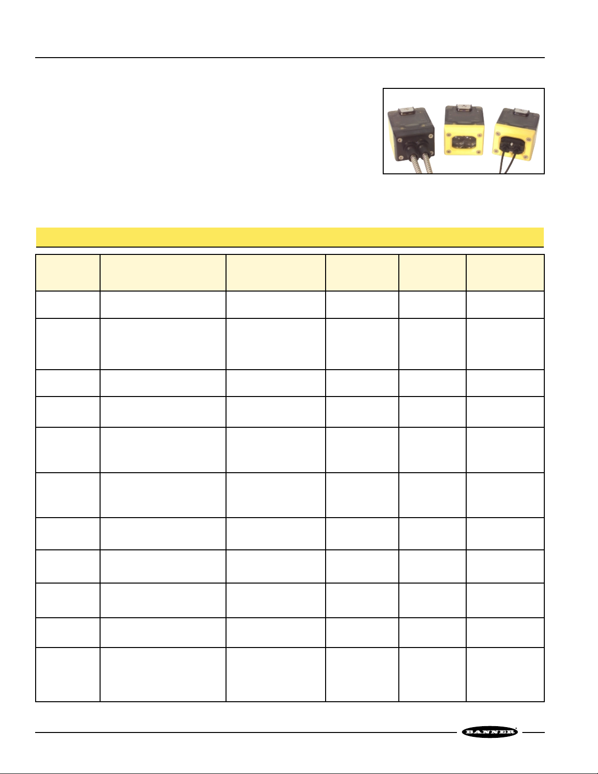
OMNI-BEAM is a modular self-contained sensor. It is made up of a sensor head and a
power block; an optional plug-in timing logic module may be added easily. The three
modular components, sold separately, simply plug and bolt together — without
interwiring — to create a complete self-contained photoelectric sensor tailored to a
particular application’s exact sensing requirements.
The sensor lenses and modular components are all field-replaceable. OMNI-BEAM’s
modular design makes change-out of any component quick and easy.
*U.S. Patent 4965548
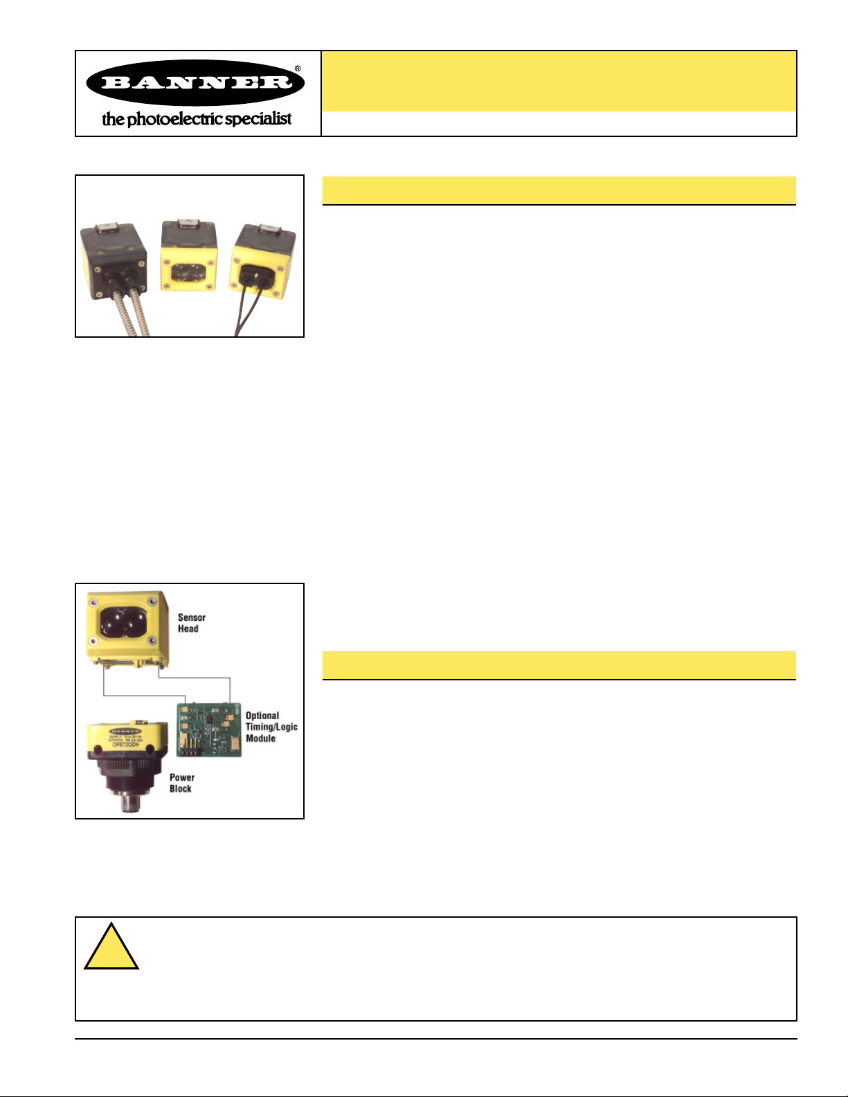
Figure 1. OMNI-BEAM sensor head and
power block bolt and plug
together quickly and easily; an
optional timing logic module
may be added at any time.
!
Page 2
OMNI-BEAM Sensor Heads
page
2
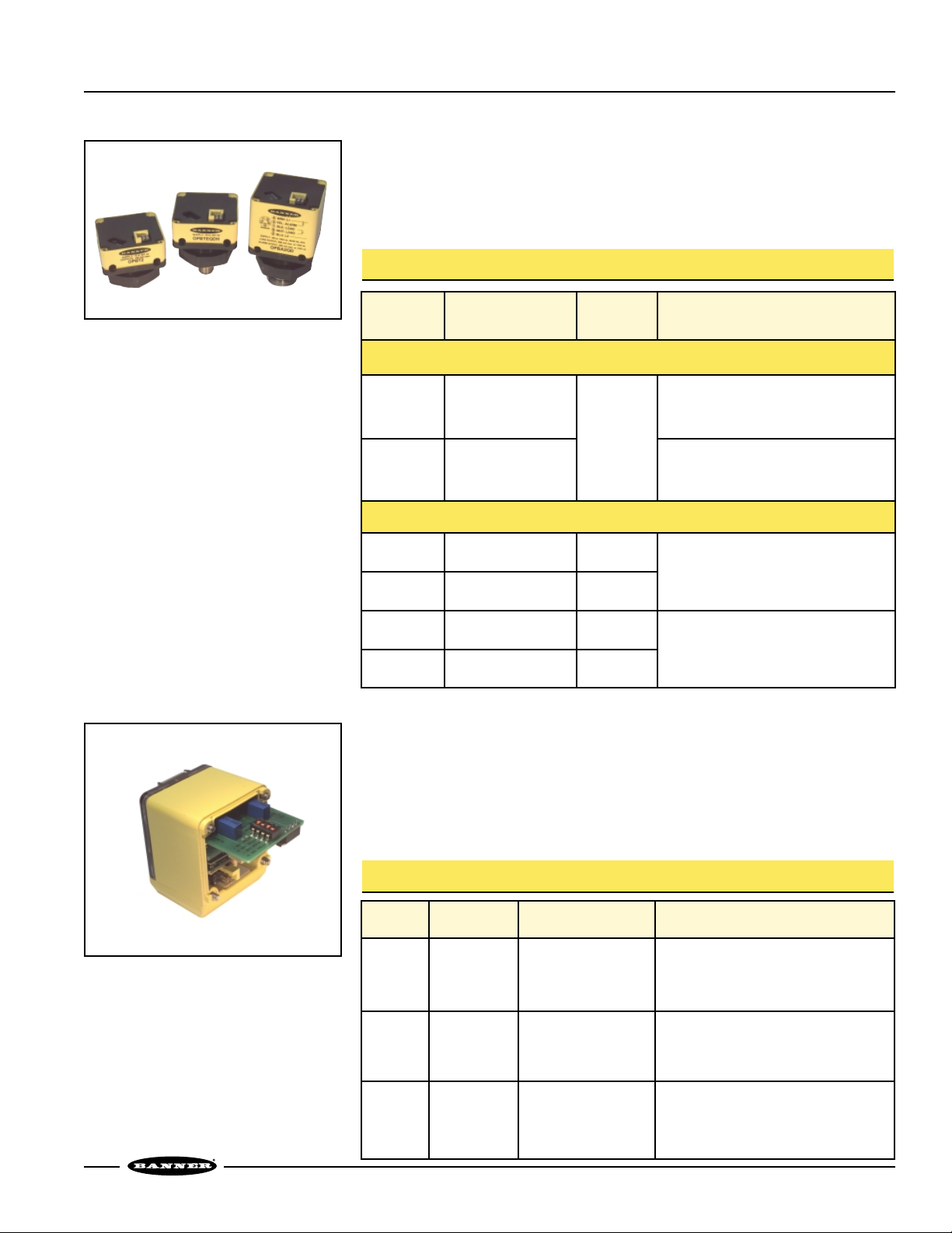
Sensor Heads
A sensor head module is available for every sensing situation. Sensor heads bolt
directly onto the power block, and are fully gasketed for protection against
environmental elements. The D.A.T.A. self-diagnostic feature is standard on all OMNIBEAM sensor heads (except emitters and model OSBFAC). Select from most sensing
modes, with infrared or visible red, green or blue sensing beams available.
Figure 2. OMNI-BEAM sensor heads are
available for most sensing
modes, including fiber optic
models.
Model Sensing Mode Light Source Range Response Repeatability
OSBE
OSBR
Opposed emitter
Opposed receiver
Infrared,
880 nm
45 m (150') 2 ms 0.01 ms
OSBLV
OSBLVAG
Non-polarized retroreflective
Polarized retroreflective
Visible red
650 nm
0.15 to 9 m
(6' to 30')
0.3 to 4.5 m
(12" to 15')
4 ms 0.2 ms
OSBD
OSBDX
Short-range diffuse
Long-range diffuse
Infrared,
880 nm
300 mm (12")
2 m (6.5')
2 ms
15 ms
0.1 ms
1 ms
OSBCV
OSBCVG
OSBCVB
Convergent
Visible red, 650 nm
Visible green, 525 nm
Visible blue, 475 nm
38 mm (1.5")
Focus
4 ms 0.2 ms
OSBF
OSBFVG
OSBFVB
Glass fiber optic
–high speed
Infrared, 880 nm
Visible green, 525 nm
Visible blue, 475 nm
Range varies with
fiber optics used
2 ms 0.1 ms
OSBFX
Glass fiber optic
–high power
Infrared, 880 nm
Range varies with
fiber optics used
15 ms 1 ms
OSBFP
OSBFPG
OSBFPB
Plastic fiber optic
Visible red, 650 nm
Visible green, 525 nm
Visible blue, 475 nm
Range varies with
fiber optics used
2 ms 0.1 ms
OMNI-BEAM Sensor Head Models
OSBLVAGC
Polarized retroreflective, clear
object detection
Visible red
650 nm
4 m (12') 4 ms 0.2 ms
OSBFV
Glass fiber optic
–high speed
Visible red, 650 nm
Range varies with
fiber optics used
2 ms 0.1 ms
OSBEF
OSBRF
Glass fiber optic emitter
Glass fiber optic receiver
Infrared, 880 nm
Range varies with
fiber optics used
2 ms 0.01 ms
OSBFAC
Glass fiber optic
–ac-coupled
Infrared, 880 nm
Range varies with
fiber optics used
1 ms 0.01 ms
NOTE: See pages 9 and 10 for Excess Gain and Beam Pattern curves.
Page 3
OMNI-BEAM Sensor Heads
page
3
OMNI-BEAM Power Blocks
Power Blocks
The power block determines the sensor operating voltage and also the sensor output
switch configuration. Models are available with a built-in 2 m (6.5') or 9 m (30')
cable, or with either Mini-style or Euro-style quick-disconnect (“QD”) plug-in cable
fittings. Emitter power blocks have no output circuitry.
Figure 3. OMNI-BEAM power blocks
provide the input and output
circuitry for OMNI-BEAM sensor
heads. Select models for either
ac or dc power.
OPBA2
OPBA2QD
2 m (6.5')
5-Pin Mini QD
105-130V ac
SPST solid-state ac relay
Two outputs: Load and Alarm
OPBB2
OPBB2QD
2 m (6.5')
5-Pin Mini QD
Models
210-250V ac
Cable
0PBAE
OPBAEQD
Supply
Voltage
Output Type
2 m (6.5')
5-Pin Mini QD
AC Voltage
(see data sheet p/n 03531 packed with the power block)
105-130V ac
No output:
for powering emitter only sensor heads
OPBBE
OPBBEQD
2 m (6.5')
5-Pin Mini QD
210-250V ac
OPBTE
OPBTEQD
OPBTEQDH
2 m (6.5')
4-Pin Mini QD
4-Pin Euro QD
No output:
for powering emitter only sensor heads
OPBT2
OPBT2QD
OPBT2QDH
2 m (6.5')
4-Pin Mini QD
4-Pin Euro QD
10-30V dc
Bi-Modal
™
NPN/PNP
Two outputs: Load and Alarm
DC Voltage
(see data sheet p/n 03532 packed with the power block)
NOTE: 9 m (30') cables are availabe by adding the suffix “w/30” to the model number
of any cabled power block (for example, OPBT2 w/30).
Optional Timing Logic Modules
Timing logic may be added at any time, using one of three timing delay and pulse
logic modules. Installation is simple and quick; the logic modules simply slide into the
sensor head (see Figure 4). Program them for timing functions and ranges via four
DIP switches; each module includes easily accessible 15-turn clutched potentiometers
for accurate timing adjustments.
Figure 4. OMNI-BEAM optional timing
logic modules
Logic Function
ONE-SHOT pulse timer or
DELAYED ONE-SHOT
logic timer
OLM8
ON-DELAY or OFF-DELAY
or ON/OFF DELAY
Pulse Timer
Logic Module
Delay: 0.01 to 1 sec,
0.15 to 15 sec, or none
Pulse: 0.01 to 1 sec, 0.15 to 15 sec
Models Type Timing Ranges
ONE-SHOT pulse timer or
DELAYED ONE-SHOT
logic timer
OLM5
Delay Timer
Logic Module
OLM8M1
ON-Delay: 0.01 to 1 sec,
0.15 to 15 sec, or none
OFF-Delay: 0.01 to 1 sec,
0.15 to 15 sec, or none
Pulse Timer
Logic Module
Delay: 0.002 to 0.1 sec,
0.03 to 1.5 sec, or none
Pulse: 0.002 to 0.1 sec,
0.03 to 1.5 sec
OMNI-BEAM Timing Logic Modules
(see data sheet p/n 03533 packed with the module)
Page 4
OMNI-BEAM Sensor Heads
page
4
Figure 5. OMNI-BEAM program switches
Alarm N/O
ON
OFF
Standard
Hysteresis
Low
Fine
Scale
Standard
Dark Operate
Alarm N/C Light Operate
1
OFF
234
Figure 6. OMNI-BEAM program switch
configuration
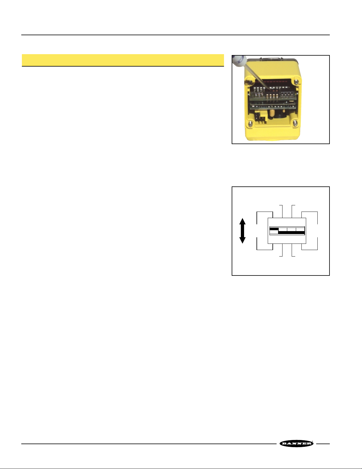
Sensor Head Programming
DIP Switch Settings
OMNI-BEAM sensor heads are field-programmable for four operating parameters. To
access the four programming DIP switches (see figure 5), remove the sensor block
from the power block.
Switch #1, Sensing Hysteresis
ON: Standard hysteresis.
OFF: Low hysteresis; should be used only when all sensing conditions remain
completely stable.
Hysteresis is an electronic sensor requirement that the amount of received light
needed to energize the sensor’s output not be equal to the amount needed to release
the output. This differential prevents the sensing output from “buzzing” or
“chattering” when the received light signal is at or near the sensing threshold level.
The standard setting should be used always, except for low-contrast applications
such as the detection of subtle differences in reflectivity.
Switch #2, Alarm Output Configuration
ON: Alarm output is normally open (it conducts with an alarm).
OFF: Alarm output is normally closed (the output opens during an alarm).
Normally closed mode (OFF) is recommended; it allows a system controller to
recognize a sensor power loss or an open sensor output as an alarm condition.
Normally open alarm mode (ON) should be used when the alarm outputs of multiple
OMNI-BEAMs are wired in parallel to a common alarm or alarm input.
Switch #3, Light or Dark Operate
ON: Dark Operate mode; the output energizes (after a time delay, if applicable) when
the received light level is less than the sensing threshold (4 or fewer D.A.T.A.
lights ON).
OFF: Light Operate mode; the sensor’s load output energizes (after a time delay, if
applicable) when the received light level is greater than the sensing threshold (5
or more D.A.T.A. lights ON).
Switch #4, Scale Factor for the D.A.T.A. Signal Strength Indicator Display
ON: Fine scale.
OFF: Standard scale.
This switch should always be OFF, except for close differential sensing situations (for
example, some color registration applications, which also require the Low hysteresis
setting/switch #1 OFF).
Factory Settings
The following are the factory program settings for OMNI-BEAM sensor head DIP
switches.
Switch #1: ON (Standard hysteresis)
Switch #2: OFF (Normally Closed alarm output)
Switch #3: OFF (Light Operate load output)
Switch #4: OFF (Standard Scale Factor for signal strength display)
Page 5

OMNI-BEAM Sensor Heads
page
5
Figure 6. OMNI-BEAM D.A.T.A. LEDs
Using the D.A.T.A. Sensor Self-Diagnostic Feature
Banner’s exclusive D.A.T.A. feature warns of marginal sensing conditions, usually
before a sensing failure occurs, by flashing one or more lights in its multiple-LED
array, and by sending a warning signal to the system logic controller (or directly to an
audible or visual alarm). The chart below describes the meanings of the possible
signals.
Flashing LED Problem Description
#1 Moisture Alert
Severe moisture is inside the sensor head, caused by condensation or by entry of moisture when the
access cover is removed.
#2
High Temperature
Alert
The temperature inside the sensor head exceeds +70°C (+158°F).
#3
Low Voltage
or
Overload Alert
Sensor supply voltage is below the minimum specified for the power block in use. Power block outputs
also shut down to prevent damage to the load(s) from low voltage.
DC power blocks OPBT2, OPBT2QD, or OPBT2QDH: Either the load output or the alarm output is
shorted. Both outputs will be inhibited, and the circuit will “retry” the outputs every 1/10 second. The
outputs automatically reset and function normally when the short is corrected.
#9
High Gain
Warning
The “dark” signal never goes below #4 on the display; decrease the Gain setting. There are two possible
causes:
1) The “dark” signal slowly increases and remains at the #4 level for a predetermined delay time,
commonly caused by a gradual increase of unwanted background reflections in reflective sensing
modes (such as diffuse or convergent). The alarm will reset as soon as the cause of the unwanted
light signal is removed, or if the Gain control setting is reduced to bring the “dark” condition below
the #4 level.
2) The “dark” signal does not fall below the #4 level during a sensing event. The alarm automatically
resets when the “dark” sensing level falls below the #4 level (accomplished by reducing the Gain
control setting and/or by removing the cause of unwanted light return in the “dark” condition).
#10
Low Gain Warning
The “light” signal never goes above #5 on the display; increase the Gain setting. There are two possible
causes:
1) The “light” signal slowly decreases to the #5 level and remains at that level for a predetermined
delay. This most commonly occurs in opposed or retroreflective sensing systems, caused by a
gradual decrease in light in the unblocked condition, due to obscured lenses or sensor
misalignment. The alarm will reset when the light signal strength exceeds the #5 level.
2) The “light” signal does not exceed the #5 level during a sensing event. The alarm automatically
resets when the “light” signal exceeds the #5 level (accomplished by increasing the GAIN control
setting and/or cleaning the lens and realigning the sensor).
#9 and #10
Low Contrast
Warning
The lights flash simultaneously to indicate inadequate optical contrast for reliable sensing (the “light”
condition is at the #5 level and the “dark” condition is at the #4 level). If this occurs, re-evaluate the
application to find ways to increase the differential between the “light” and “dark” conditions. The alarm
automatically resets when the “light” signal exceeds the #5 level and the “dark” signal falls below the #4
level.
Page 6

OMNI-BEAM Sensor Heads
page
6
Sense and Load LED Indicators
The Sense LED indicates when a target has been sensed. When the sensor head is
programmed for Light Operate, it lights when the received light signal exceeds the #5
threshold. When programmed for Dark Operate, it lights when the received light
signal falls below the #5 threshold. See figure 7.
The Load indicator LED lights whenever the output is energized (after the timing
function, if applicable).
Measuring Excess Gain
OMNI-BEAM’s D.A.T.A. indicator display may be used to measure the excess gain and
contrast during sensing, installation, or maintenance.
Excess gain is a measurement of the amount of light energy falling on a photoelectric
sensor’s receiver, over and above the minimum amount needed to operate the
sensor’s amplifier. Excess gain is expressed as a ratio:
Excess gain (E.G.) = light energy falling on receiver
amplifier threshold
The amplifier threshold is the point at which the sensor’s output switches
(corresponding to the #5 level of the D.A.T.A. display). When LEDs #1 through #5 are
ON, the excess gain of the received light signal is equal to “1x.” The chart below
shows how excess gain relates to the D.A.T.A. light array indication.
Figure 7. Sense and Load indicators
Relationship Between Excess Gain and D.A.T.A System Lights
D.A.T.A. Light
LED Number
STANDARD
Scale Factor
FINE*
Scale Factor
#1
#2
#3
#4
#5
#6
#7
#8
#9
#10
0.25x Excess Gain
0.35x Excess Gain
0.5x Excess Gain
0.7x
Excess Gain
1.0x Excess Gain
1.3x Excess Gain
1.7x Excess Gain
2.2x Excess Gain
2.9x Excess Gain
3.7x Excess Gain (or more)
0.5x Excess Gain
0.7x Excess Gain
0.8x Excess Gain
0.9x
Excess Gain
1.0x Excess Gain
1.1x Excess Gain
1.2x Excess Gain
1.3x Excess Gain
1.7x Excess Gain
2.2x Excess Gain (or more)
Page 7

OMNI-BEAM Sensor Heads
page
7
Figure 8. Dark condition example:
D.A.T.A. system LEDs #1
and #2 lit.
Figure 9. Light condition example:
D.A.T.A. system LEDs
#1 through #8 lit.
Measuring Sensing Contrast
Contrast is the ratio of the amount of light falling on the receiver in the “light” state,
compared to the “dark” state (sometimes called “light-to-dark ratio”). Optimizing the
contrast in any sensing situation increases the sensing reliability. Contrast may be
calculated if excess gain values are known for both the light and dark conditions:
Contrast = Excess gain (light condition)
Excess gain (dark condition)
To determine the contrast for any sensing application, present both the Light and Dark
conditions to the OMNI-BEAM, and note how many LEDs in the D.A.T.A. display are
ON for each condition. Compute the ratio from the corresponding excess gain
numbers (from the chart on page 6) for the two conditions.
For example, if LEDs #1 through #8 come ON in the Light condition and LEDs #1 and
#2 come ON in the Dark condition (assuming Standard scale factor), contrast is
calculated as follows:
Light condition: 2.2x excess gain
Dark condition: 0.35x excess gain
Contrast = 2.2x = 6
0.35x
This value is expressed as 6:1 (“six-to-one”).
The best sensor adjustment will cause all ten D.A.T.A. LEDs to come ON for the Light
condition, and none in the Dark condition. In this situation (such as an application in
which a box breaks the beam of an opposed-mode emitter/receiver pair):
Contrast is greater than 3.7x = 15
0.25x
While it is not always possible to adjust a sensor to maintain this much contrast, it is
important to always adjust for the maximum possible contrast. The D.A.T.A. feature
makes this easy. The chart below gives general guidelines for contrast values.
Contrast Values and Corresponding Guidelines
Contrast Recommendation
1.2 or Less Unreliable. Evaluate alternative sensing schemes.
1.2 to 2
Poor Contrast. Use the LOW hysteresis setting and the FINE
scale factor.
2 to 3
Low Contrast. Sensing environment must remain per fectly clean and
all other sensing variables must remain stable.
3 to 10
Good Contrast. Minor sensing system variables will not affect
sensing reliabilty.
10 or Greater
Excellent Contrast. Sensing should remain reliable as long as the
sensing system has enough excess gain for operation.
Page 8

OMNI-BEAM Sensor Heads
page
8
Certifications
Supply Voltage and Current Supplied by OMNI-BEAM power block
Output Response Time See individual sensing heads for response times (page 2)
200 millisecond delay on power-up: outputs are non-conducting during this time.
Adjustments OMNI-BEAM sensor heads are field-programmable for four operating parameters. A set of four
programming DIP switches is located at the base of the sensor head and is accessible with the sensor
head removed from the power block (see page 4).
Switch #1 selects the amount of sensing hysteresis
Switch #2 selects the alarm output configuration
Switch #3 selects LIGHT operate (switch #3 OFF) or DARK operate (switch #3 ON)
Switch #4 selects the STANDARD (switch #4 OFF) or FINE (switch #4 ON) scale factor for the D.A.T.A.
light signal strength indicator array
15-turn slotted brass screw Gain (sensitivity) adjustment potentiometer (clutched at both ends of travel)
Indicators Sense and Load indicator LEDs are located on the top of the sensor head on either side of the D.A.T.A. array.
Sense LED indicates when a target has been sensed
Load LED lights whenever the load output is energized
Also, Banner’s exclusive D.A.T.A. sensor self-diagnostic system located on the top of the sensor head
warns of marginal sensing conditions usually before a sensing failure occurs (except on model OSBFAC).
Construction Sensor heads are molded of rugged reinforced thermoplastic polyester; top view window is LEXAN
®
polycarbonate; acrylic lenses; stainless steel hardware
Environmental Rating Meets NEMA standards 1, 2, 3, 3S, 4, 12, and 13; IEC IP66 when assembled to power block
Operating Temperature Temperature: -40° to +70°C (-40° to +158°F)
Maximum relative humidity: 90% at 50°C (non-condensing)
OMNI-BEAM Sensor Head Specifications
OMNI-BEAM Dimensions – Sensor Head Shown Assembled to Power Block
OMNI-BEAM Sensor with Attached Cable
Transparent Cover (Gasketed)
View: D.A.T.A. Lights
Sensing Status
Output Load
Remove to Access:
Sensitivity (Gain) Adjustment
Logic Timing Adjustments
44.5 mm (1.75")
57.4 mm w/DC
(2.26")
38.1 mm w/DC
(1.50")
60.5 mm w/AC
(2.38")
79.8 mm w/AC
(3.14")
7.1 mm
(0.28")
30.0 mm
(1.18")
30.0 mm
(1.18")
7.1 mm
(0.28")
Internal Thread
(1/2-14NPSM)
External Thread
M30 X 1.5
5.6 mm (0.22")
Lens
Centerline
2 m ( 6.5' Cable)
76.2 mm w/DC Power Block
(3.00")
98.6mm w/AC Power Block
(3.88")
#10 Screw
Clearance (4)
Cross-hole design for front,
back, or side mounting
54.6 mm*
(2.15")
Hex Nut
Supplied
*
61.7 mm (2.43") for OSBCV, CVG, CVB
60.5 mm (2.38") for OSBF, FV, FVG, FVB, FX, EF, RF, FAC
59.8 mm (2.35") for OSBFP, FPG, FPB
14 mm (0.6")
Mini-style QD Connector
15 mm (0.6")
Euro-style QD Connector
OMNI-BEAM Sensor with Quick Disconnect
Mini-Style Euro-Style
LEXAN®is a registered trademark of General Electric Company
Page 9

OMNI-BEAM Sensor Heads
page
9
Excess Gain Curves
OSBE & OSBR
(Opposed)
OSBLV
(Retroreflective)
OSBLVAG
(Polarized Retroreflective)
OSBD
(Diffuse)
1
10
100
1 m
3.3 ft
10 m
33 ft
100 m
330 ft
0.1 m
0.33 ft
1000
E
X
C
E
S
S
G
A
I
N
DISTANCE
OSBE & OSBR
Opposed Mode
1
10
100
.10 m
.33 ft
1.0 m
3.3 ft
10 m
33 ft
.01 m
.033 ft
E
X
C
E
S
S
G
A
I
N
DISTANCE
1000
OSBLV
Retroreflective Mode
With BRT-3 Reflector
1
10
100
.10 m
.33 ft
1.0 m
3.3 ft
10 m
33 ft
.01 m
.033 ft
E
X
C
E
S
S
G
A
I
N
DISTANCE
1000
OSBLVAG
Retroreflective Mode
W/BRT-3 Reflector
1
10
100
10 mm
.4 in
100 mm
4 in
1000 mm
40 in
1 mm
.04 in
1000
E
X
C
E
S
S
G
A
I
N
DISTANCE
OSBD
Diffuse Mode
OSBDX
(Diffuse)
OSBCV
(Convergent)
OSBCVG
(Convergent)
OSBCVB
(Convergent)
OSBF
(Opposed)
OSBF
(Diffuse)
OSBFVG
(Diffuse)
OSBFVB
(Diffuse)
OSBFX
(Opposed)
OSBFX
(Diffuse)
OSBFP
(Opposed)
OSBFP
(Diffuse)
OSBFPG
(Diffuse)
OSBFPB
(Diffuse)
OSBLVAGC: Refer to data sheet p/n 34151
OSBFV: Refer to data sheet p/n 03543
OSBEF/OSBRF: Refer to data sheet p/n 03546
OSBFAC: Refer to data sheet p/n 03553
1000
E
X
C
100
E
S
S
10
G
A
I
N
1
0.01 m
0.033 ft
1000
E
X
C
100
E
S
S
10
G
A
N
X
C
S
S
G
A
N
E
X
C
E
S
S
G
A
N
I
1
1 mm
.04 in
1000
E
100
E
10
I
1
0.01 m
0.03 ft
1000
100
10
I
1
.1 mm
.004 in
IT13S Fibers
IT13S fibers
0.1 m
0.33 ft
DISTANCE
10 mm
.4 in
DISTANCE
0.1 m
0.33 ft
DISTANCE
1 mm
.04 in
DISTANCE
OSBDX
Diffuse Mode
1.0 m
3.3 ft
OSBF
Opposed Mode
IT23S Fibers
100 mm
4 in
OSBFX
Opposed Mode
IT23S fibers
1.0 m
3.3 ft
OSBFPG
Diffuse Mode
Plastic Fiber
PBT46U Fiber
10 mm
.4 in
10 m
33 ft
1000 mm
40 in
10 m
33 ft
100 mm
4 in
1000
E
X
C
100
E
S
S
10
G
A
I
N
1
1 mm
.04 in
1000
E
X
C
100
E
S
S
10
G
A
I
BT13S Fiber
N
1
1 mm
.04 in
1000
E
X
C
100
E
S
S
10
G
A
I
N
1
1 mm
0.04 in
1000
E
X
C
100
E
S
S
10
G
A
I
N
1
.1 mm
.004 in
10 mm
10 mm
BT13S Fiber
10 mm
0.4 in
1 mm
.04 in
.4 in
DISTANCE
BT23S Fiber
.4 in
DISTANCE
DISTANCE
DISTANCE
OSBCV
Convergent Mode
100 mm
4 in
OSBF
Diffuse Mode
100 mm
4 in
OSBFX
Diffuse Mode
BT23S Fiber
100 mm
4.0 in
OSBFPB
Diffuse Mode
Plastic Fiber
PBT46U Fiber
10 mm
.4 in
1000 mm
40 in
1000 mm
40 in
1000 mm
40 in
100 mm
4 in
1000
E
X
C
100
E
S
S
10
G
A
I
N
1
1 mm
.04 in
1000
E
X
C
100
E
S
S
10
G
A
I
N
1
0.1 mm
0.004 in
1000
E
X
C
100
E
S
S
10
G
A
I
N
1
1 mm
.04 in
PIT26U Fibers
10 mm
.4 in
DISTANCE
1.0 mm
0.04 in
DISTANCE
10 mm
.40 in
DISTANCE
OSBFVG
BT23S Fiber
PIT46U Fibers
Convergent Mode
100 mm
4 in
Diffuse Mode
10 mm
0.4 in
OSBFP
Opposed Mode
Plastic Fibers
100 mm
4.0 in
OSBCVG
P
1000 mm
100 mm
1000 mm
40 in
4 in
40 in
1000
E
X
C
100
E
S
S
10
G
A
I
N
1
1 mm
.04 in
1000
E
X
C
100
E
S
S
10
G
A
I
N
1
0.1 mm
0.004 in
1000
E
X
C
100
E
S
S
10
G
A
I
N
1
.1 mm
.004 in
10 mm
.4 in
DISTANCE
1.0 mm
0.04 in
DISTANCE
PBT26U Fiber
1 mm
.04 in
DISTANCE
BT23S Fiber
OSBCVB
Convergent Mode
100 mm
4 in
OSBFVB
Diffuse Mode
10 mm
0.4 in
OSBFP
Diffuse Mode
PBT46U Fiber
10 mm
.4 in
1000 mm
40 in
100 mm
4 in
100 mm
4 in
Page 10

OMNI-BEAM Sensor Heads
page
10
Beam Patterns
OSBE & OSBR
(Opposed)
OSBLV
(Retroreflective)
OSBLVAG
(Polarized Retroreflective)
OSBD
(Diffuse)
OSBDX
(Diffuse)
OSBCV
(Convergent)
OSBCVG
(Convergent)
OSBCVB
(Convergent)
OSBF
(Opposed)
OSBF
(Diffuse)
OSBFVG
(Diffuse)
OSBFVB
(Diffuse)
OSBFX
(Opposed)
OSBFX
(Diffuse)
OSBFP
(Opposed)
OSBFP
(Diffuse)
OSBFPG
(Diffuse)
OSBFPB
(Diffuse)
OSBLVAGC: Refer to data sheet p/n 34151
OSBFV: Refer to data sheet p/n 03543
OSBEF/OSBRF: Refer to data sheet p/n 03546
OSBFAC: Refer to data sheet p/n 03553
OSBE and OSBR
1500 mm
Opposed Mode
1000 mm
500 mm
0
500 mm
1000 mm
1500 mm
10 m
0
30 ft
OSBDX
75 mm
Diffuse Mode
50 mm
25 mm
0
25 mm
50 mm
75 mm
0.4 m
0
1.25 ft
OSBF
75 mm
Opposed Mode
50 mm
25 mm
0
IT13S IT23S
25 mm
50 mm
75 mm
100 mm
0
4 in
150 mm
100 mm
50 mm
0
IT13S Fibers
50 mm
100 mm
150 mm
0.4 m
0
15 in
20 m
60 ft
DISTANCE
0.8 m
2.5 ft
DISTANCE
200 mm
8 in
DISTANCE
IT23S Fibers
0.8 m
30 in
DISTANCE
30 m
90 ft
1.2 m
3.75 ft
300 mm
12 in
1.2 m
45 in
40 m
120 ft
1.6 m
5.0 ft
400 mm
16 in
OSBFX
Opposed Mode
1.6 m
60 in
50 m
150 ft
2.0 m
6.25 ft
500 mm
20 in
2.0 m
75 in
3.0 in
2.0 in
1.0 in
0
1.0 in
2.0 in
3.0 in
3 in
2 in
1 in
0
1 in
2 in
3 in
6.0 in
4.0 in
2.0 in
0
2.0 in
4.0 in
6.0 in
60 in
40 in
20 in
0
20 in
40 in
60 in
OSBLV
150 mm
Retroreflective Mode
100 mm
50 mm
0
50 mm
100 mm
150 mm
0
2.4 mm
1.6 mm
0.8 mm
0
0.8 mm
1.6 mm
2.4 mm
12.5 mm
0
0.50 in
1.9 mm
1.3 mm
0.65 mm
0
0.65 mm
1.3 mm
1.9 mm
7.5 mm
0
0.3 in
3.8 mm
2.5 mm
BT13S Fiber
1.3 mm
0
1.3 mm
2.5 mm
3.8 mm
25 mm
0
4 m
2 m
13 ft
6.6 ft
DISTANCE
OSBCV
Convergent Mode
25 mm
1.0 in
DISTANCE
OSBF
Diffuse Mode
15 mm
0.6 in
DISTANCE
50 mm
2 in
1 in
DISTANCE
With BRT-3 Reflector
8 m
6 m
26 ft
20 ft
50 mm
37.5 mm
2.0 in
1.5 in
BT23SBT13S
30 mm
22.5 mm
1.2 in
0.9 in
OSBFX
Diffuse Mode
BT23S Fiber
100 mm
75 mm
4 in
3 in
10 m
33 ft
62.5 mm
2.5 in
37.5 mm
1.5 in
125 mm
5 in
75 mm
50 mm
25 mm
0
25 mm
50 mm
75 mm
0
2.4 mm
1.6 mm
0.8 mm
0
0.8 mm
1.6 mm
2.4 mm
0
1.8 mm
1.2 mm
0.6 mm
0
0.6 mm
1.2 mm
1.8 mm
0
OSBFP
45 mm
Opposed Mode
30 mm
15 mm
0
15 mm
30 mm
45 mm
0
OSBLVAG
Retroreflective Mode
12.5 mm
0.50 in
OSBFVG
Diffuse Mode
PIT26U
25 mm
6.0 in
4.0 in
2.0 in
0
2.0 in
4.0 in
6.0 in
0.09 in
0.06 in
0.03 in
0
0.03 in
0.06 in
0.09 in
0.075 in
0.050 in
0.025 in
0
0.025 in
0.050 in
0.075 in
0.15 in
0.10 in
0.05 in
0
0.05 in
0.10 in
0.15 in
2 m
1 m
6.6 ft
3.3 ft
DISTANCE
OSBCVG
Convergent Mode
25 mm
1.0 in
10 mm
5 mm
0.4 in
0.2 in
50 mm
2 in
1 in
With BRT-3 Reflector
3 m
10 ft
37.5 mm
1.5 in
DISTANCE
BT23S Fiber
15 mm
0.6 in
DISTANCE
75 mm
3 in
DISTANCE
4 m
13 ft
50 mm
2.0 in
20 mm
0.8 in
PIT46U
100 mm
4 in
P
5 m
16 ft
62.5 mm
2.5 in
25 mm
1.0 in
125 mm
5 in
3.0 in
2.0 in
1.0 in
0
1.0 in
2.0 in
3.0 in
0.09 in
0.06 in
0.03 in
0
0.03 in
0.06 in
0.09 in
0.075 in
0.050 in
0.025 in
0
0.025 in
0.050 in
0.075 in
1.8 in
1.2 in
0.6 in
0
0.6 in
1.2 in
1.8 in
7.5 mm
5.0 mm
2.5 mm
0
2.5 mm
5.0 mm
7.5 mm
0
2.4 mm
1.6 mm
0.8 mm
0
0.8 mm
1.6 mm
2.4 mm
0
1.8 mm
1.2 mm
0.6 mm
0
0.6 mm
1.2 mm
1.8 mm
0
OSBFP
3.8 mm
Diffuse Mode
2.5 mm
1.2 mm
0
1.2 mm
2.5 mm
3.8 mm
0
OSBD
Diffuse Mode
75 mm
3 in
OSBCVB
Convergent Mode
12.5 mm
0.50 in
OSBFVB
Diffuse Mode
5 mm
0.2 in
PBT26U
7.5 mm
0.3 in
150 mm
6 in
DISTANCE
25 mm
1.0 in
DISTANCE
10 mm
0.4 in
DISTANCE
15 mm
0.6 in
DISTANCE
225 mm
9 in
37.5 mm
1.5 in
15 mm
0.6 in
PBT46U
22.5 mm
0.9 in
300 mm
50 mm
2.0 in
BT23S Fiber
20 mm
0.8 in
30 mm
1.2 in
12 in
375 mm
15 in
62.5 mm
2.5 in
25 mm
1.0 in
37.5 mm
1.5 in
0.3 in
0.2 in
0.1 in
0
0.1 in
0.2 in
0.3 in
0.09 in
0.06 in
0.03 in
0
0.03 in
0.06 in
0.09 in
0.075 in
0.050 in
0.025 in
0
0.025 in
0.050 in
0.075 in
0.15 in
0.10 in
0.05 in
0
0.05 in
0.10 in
0.15 in
3.0 mm
2.0 mm
1.0 mm
1.0 mm
2.0 mm
3.0 mm
0
0
OSBFPG
Diffuse Mode
4 mm
0.15 in
PBT46U
8 mm
0.30 in
DISTANCE
12 mm
0.45 in
16 mm
0.60 in
20 mm
0.75 in
0.12 in
0.08 in
0.04 in
0
0.04 in
0.08 in
0.12 in
3.0 mm
2.0 mm
1.0 mm
1.0 mm
2.0 mm
3.0 mm
0
0
OSBFPB
Diffuse Mode
4 mm
0.15 in
PBT46U
8 mm
0.30 in
DISTANCE
12 mm
0.45 in
16 mm
0.60 in
20 mm
0.75 in
0.12 in
0.08 in
0.04 in
0
0.04 in
0.08 in
0.12 in
Page 11

OMNI-BEAM Sensor Heads
page
11
Accessories
Mounting Brackets
SMB30C
SMB30SC
SMB30MM
• 30 mm split clamp, black reinforced thermoplastic
polyester
• Stainless steel hardware included
• Compact 30 mm swivel bracket
• Excellent range of articulation
• 30 mm, 11-gauge stainless steel
• Clearance for M6 (1/4") hardware
SMB30UR
• Rugged stainless steel construction
• Swivel mount
56.0 mm
63.0 mm
(2.48")
13.5 mm
(0.53")
(2.20")
45.0 mm
(1.77")
31.5 mm
(1.24")
2.5 mm
(0.10")
13 mm
(0.5")
Nut Plate
M5 x 0.8
x 80 mm
Screw (2)
50.8 mm
58.7 mm
(2.31")
(2.00")
66.5 mm
(2.62")
30.0 mm
(1.18")
12.7 mm
(0.50")
29.0 mm
(1.14")
ø30.5 mm
(1.20")
8X #10-32
38.1 mm
(1.50")
50.8 mm
(2.00")
70.0 mm
(2.75")
9.7 mm
(0.38")
59.9 mm
(2.36")
30.0 mm
(1.18")
23.1 mm
(0.91")
15.2 mm
(0.60")
31.8 mm
(1.75")
3.4 mm
(0.14")
89.8 mm
(3.54")
82.2 mm
(3.24")
50.8 mm
(2.00")
66.0 mm
(2.6")
76.2 mm
(3.00")
15.2 mm
(0.60")
5X 7.1 mm
(0.28")
ø57.2 (2.25")
25.4 mm
(1.0")
22.4 mm
(0.88")
9.7 mm
(0.38")
6X 1/4-28
3.4 mm
(0.14")
SMB30UR Top
60º
27.9 mm
(1.11")
31.8 mm
(1.25")
SMB30UR Bottom
31.8 mm
(1.25")
77.1 mm
(3.04")
90º
25.4 mm
1.00")
ø38.1 mm
(1.50")
57.1 mm
(2.25")
12.7 mm
(0.50")
2X ø7.1
(0.28")
172.0 mm
(6.77")
57.2 mm
(2.25")
ø 6.4 mm
(0.25")
25.4 mm
(1.00")
35.1 mm
(1.38")
69.9 mm
(2.75")
35.1 mm
(1.38")
7.1 mm x 90°
(0.28") (2 Slots)
R 25.4 mm
(1.00")
25.4 mm
(1.00")
57.2 mm
(2.25")
1/4 x 28 x 1/2"
Screw
2X 1/4"
Lock Washer
Flat Washer
2X
2X 1/4"
76.2 mm
(3.00")
Page 12

Banner Engineering Corp., 9714 Tenth Ave. No., Minneapolis, MN 55441 • Phone: 612.544.3164 • Fax: 612.544.3213 • E-mail: sensors@baneng.com
OMNI-BEAM Sensor Heads
Replacement Lenses
OMNI-BEAM lens assemblies are field-replaceable.
Model Description
OUC-C
OUC-D
OUC-F
OUC-FP
OUC-L
OUC-LAG
Replacement lens for convergent models (model suffix CV)
Replacement lens for short range diffuse models (model suffix D)
Replacement lens for glass fiber optic models (model suffix F, FAC, FV, FX, EF, and RF)
Replacement lens for plastic fiber optic models (model suffix FP)
Replacement lens for non-polarized retroreflective and opposed models (model suffix DX, LV, E and R)
Replacement lens for polarized retroreflective models (model suffix LVAG and LVAGC)
Retroreflective Targets
Banner offers a wide selection of high-quality retroreflective targets. See Banner Product Catalog for complete information.
Cable Protector
HF1-2NPS
• Flexible black nylon cable protector
• Includes a neoprene gland that compresses around the OMNI-BEAM cable to provide an
additional seal against moisture
• Resistant to gasoline, alcohol, oil, grease, solvents and weak acids
• Working temperature range of -30° to +100°C (-22° to +212°F)
Model Description
WARRANTY: Banner Engineering Corporation warrants its products to be free from defects for one year. Banner Engineering Corporation
will repair or replace, free of charge, any product of its manufacture found to be defective at the time it is returned to the factory during the
warranty period. This warranty does not cover damage or liability for the improper application of Banner products. This warranty is in lieu
of any other warranty either expressed or implied.
 Loading...