

Page 1
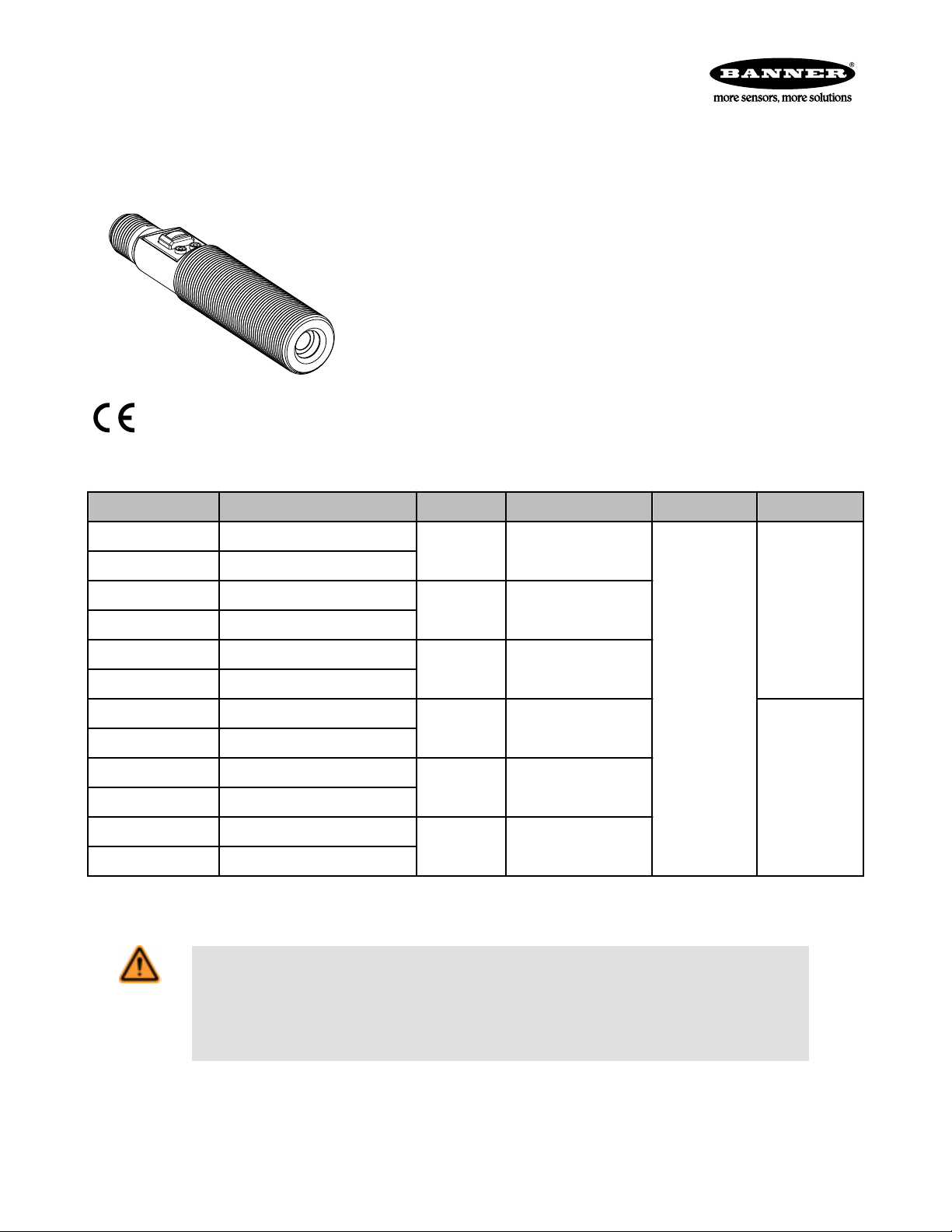
T-GAGE™ M18T Series Infrared Temperature Sensors
18 mm sensor with 0-10V and 4-20mA analog output and TEACH-mode programming
For the latest technical information about this product, including specifications, dimensions, and wiring, see www.BannerEngineering.com
Features
• Fast 75 ms response time
• Easy-to-use TEACH mode programming; no potentiometer adjustments
• Small self-contained package, no auxiliary controller needed
• Rugged encapsulated design for harsh environments
• Choose 2 meter or 9 meter unterminated cable, or 5-pin Euro-style QD connector
• Product motion not required for sensing
• Remote Teach available in both Static and Dynamic modes
• Alarm output for signal maximum
• Programming for either positive or negative analog slope based on teach order
Models
Model Cable* D:S Ratio Sensing Face Supply Voltage Output
M18TUP8 5-wire, 2 m (6.5') shielded cable
M18TUP8Q 5-pin Euro-style integral QD
M18TUP6E 5-wire, 2 m (6.5') shielded cable
M18TUP6EQ 5-pin, Euro-style integral QD
M18TUP14 5-wire, 2 m (6.5') shielded cable
M18TUP14Q 5-pin, Euro-style integral QD
M18TIP8 5-wire, 2 m (6.5') shielded cable
M18TIP8Q 5-pin Euro-style integral QD
M18TIP6E 5-wire, 2 m (6.5') shielded cable
M18TIP6EQ 5-pin, Euro-style integral QD
M18TIP14 5-wire, 2 m (6.5') shielded cable
M18TIP14Q 5-pin, Euro-style integral QD
* For 9 m (30') cable, add suffix "W/30" to the model number of any cabled model (e.g., M18TUP8 W/30). A model with a QD connector
requires an accessory mating cable. See Quick-Disconnect Cables on page 8 for more information.
WARNING: Not To Be Used for Personnel Protection
Never use this product as a sensing device for personnel protection. Doing so could lead to seri-
ous injury or death. This product does NOT include the self-checking redundant circuitry necessary to
allow its use in personnel safety applications. A sensor failure or malfunction can cause either an energized or de-energized sensor output condition.
8:1 Integrated lens
6:1
14:1
8:1
6:1
14:1
Enclosed Plastic face
(for food industry use)
Germanium lens
Integrated lens
Enclosed Plastic face
(for food industry use)
Germanium lens
0 to 10V dc ana-
log, plus PNP
Alarm
12 to 30V dc
4 - 20 mA ana-
log, plus PNP
Alarm
P/N 123698_web
Rev. A
5/14/2012
Page 2
200 400 600
800 1000
Distance (mm)
Spot Size
(see table)
T-GAGE™ M18T Series Infrared Temperature Sensors
Overview
The T-GAGE analog sensor is a passive, non-contacting, temperature-based device. It is used to detect object(s) temperature within a sensing window and output a proportional voltage or current.
While it looks and operates just like an Expert™ photoelectric sensor, the TGAGE detects the infrared light energy emitted by objects, instead of its own
emitted light. The sensor uses a thermopile detector, made up of multiple infrared-sensitive elements (thermocouples) to detect this infrared energy within its
field of view (see Figure 2. Detection spot size versus distance from sensor on
page 2).
Potential applications include:
• Hot part detection (baked goods, metals, bottles, rubber)
• Ejection verification of injection-molded parts
• Flame process verification
• Hot glue detection (packaging equipment, book binding, product assembly)
• Cold part detection (frozen foods, ice, dairy)
• Roller monitoring
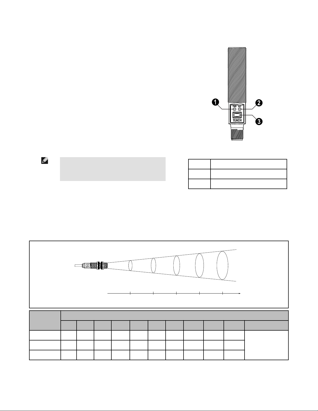
Figure 1. Sensor Features
NOTE: The T-GAGE M18T sensor is not intended for
1 Power/Teach LED
absolute temperature measurement or for safety-related fire detection use.
2 Alarm Output LED
3 TEACH Push Button
Sensing Field of View
The sensing range is determined by the sensor’s field of view (FOV), or viewing angle, combined with the size of the object(s) being
detected (see Figure 2. Detection spot size versus distance from sensor on page 2). The sensor’s distance-to- spot size ratio (D:S
ratio) is inversely related to the viewing angle; a sensor with a small viewing angle will have a large D:S ratio. The T-GAGE M18T sensors have D:S ratios of 6:1, 8:1 or 14:1. For a sensor with an 8:1 D:S ratio, the sensor’s spot size is a 1" diameter circle at a distance of
8"; farther from the sensor face the spot size will be larger.
Sensor D:S
Ratio
100 200 300 400 500 600 700 800 900 1000 Distance (mm)
Distance from Sensor Face Versus Spot Size
6:1 17 33 50 67 83 100 117 133 150 167
Spot Size (mm)8:1 13 25 38 50 63 75 88 100 113 125
14:1 7 14 21 29 36 43 50 57 64 71
Figure 2. Detection spot size versus distance from sensor
2 www.bannerengineering.com - tel: 763-544-3164 P/N 123698_web
Rev. A
Page 3
0
First
Taught
Condition
Cold
Condition
Positive Slope: Cold condition taught first
Negative Slope: Hot condition taught first
Alarm
Output
ON
Alarm
Output
ON
Hot
Condition
Second
Taught
Condition
10
4
20
Analog Output (V dc)
Analog Output (mA)
Positive Slope
Negative Slope
T-GAGE™ M18T Series Infrared Temperature Sensors
Apparent Temperature
Two factors that have a large influence on apparent temperature are the object’s emissivity and whether or not the object fills the sensor’s
field of view.
Object Emissivity:
A “blackbody” is a “perfect” emitter, with an emissivity of 1.0 at all temperatures and wavelengths. Most surfaces emit only a
fraction of the amount of thermal energy that a blackbody would. Typical T-GAGE applications will be sensing objects with
emissivities ranging from 0.5 to 0.95. Many references are available with tables of emissivity coefficients for common materials. In general, shiny unpainted metals have low emissivity, while non-glossy surfaces have high emissivity.
Shiny surfaces: a mirror or shiny surface can redirect an object’s emitted energy to an undesired location, or even bring
additional unintended thermal energy into the sensor’s field of view (see Application Note on page 6).
Object Size:
If the object being detected does not fill the sensor’s field of view, then the sensor will average the temperature of that object
and whatever else is in the sensing field of view. For the sensor to collect the maximum amount of energy, the object should
completely fill the sensor’s field of view. However, in some applications, when the object is too small, this may not be possible. In such cases, if the object is hot enough, the thermal contrast may still be adequate to trigger the sensor’s output.
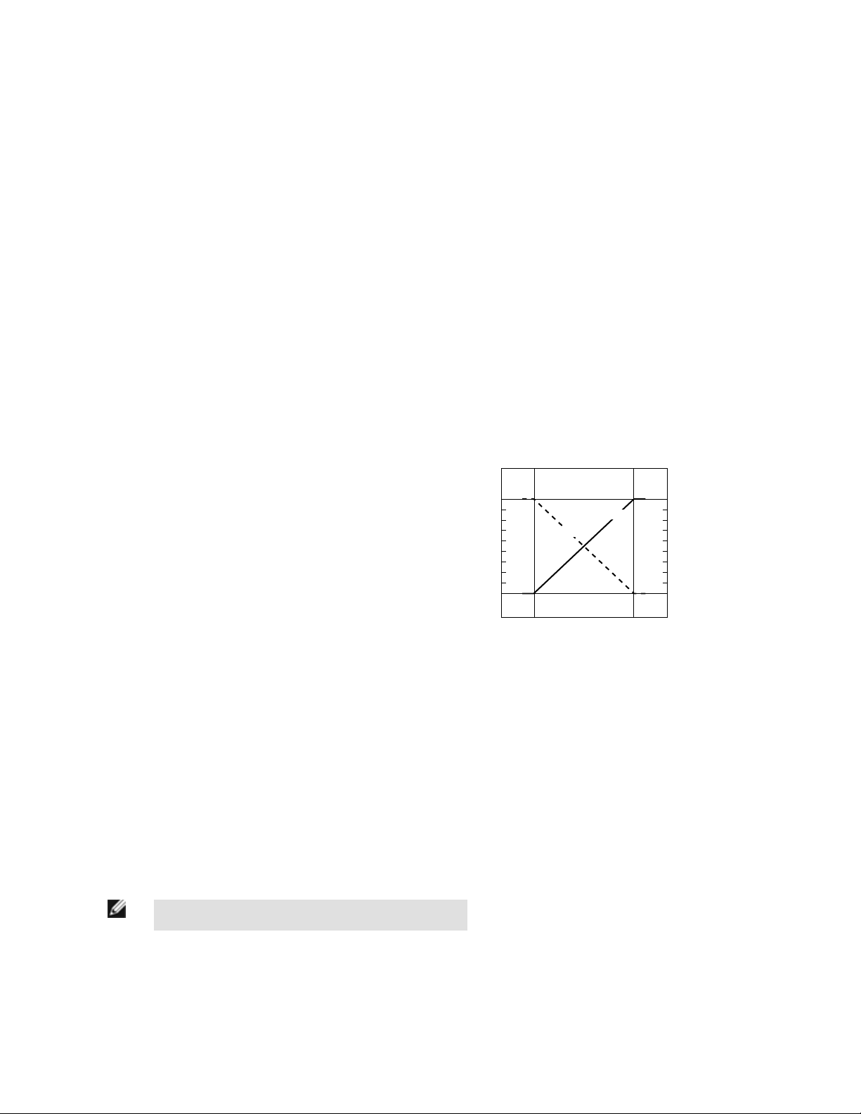
Alarm Output
The alarm output will activate when the analog output is at 10V or 20mA, depending on model (see Figure 3. Analog/Alarm outputs as a
function of taught conditions on page 3).
Analog Output
The T-GAGE analog sensor can be programmed for either positive or
negative output slope, based on the teach order (see Figure 3. Analog/
Alarm outputs as a function of taught conditions on page 3). If the cold
limit is taught first, the slope will be positive; if the hot limit is taught first,
the slope will be negative. Banner’s scalable output automatically distributes the output signal over the width of the programmed sensing window.
Figure 3. Analog/Alarm outputs as a function of taught
conditions
Sensor Programming
Two TEACH methods may be used to program the sensor:
• Teach individual minimum and maximum limits (Two-Point Static Teach), or
• Dynamic Teach for on-the-fly programming.
The sensor may be programmed either via its push button, or via a remote switch. Remote programming also may be used to disable the
push button, preventing unauthorized personnel from adjusting the programming settings. To access this feature, connect a normally
open switch between the sensor’s gray wire and dc common or connect the gray wire to a digital input (PLC).
Programming is accomplished by following the sequence of input pulses (see Teaching Limits Using Two-Point Static TEACH on page
4). The duration of each pulse (corresponding to a push button “click”), and the period between multiple pulses, are defined as “T”:
P/N 123698_web
Rev. A
NOTE: The impedance of the Remote Teach input is 3 kΩ.
0.04 seconds < T < 0.8 seconds
www.bannerengineering.com - tel: 763-544-3164 3
Page 4

T
T
2 seconds
T-GAGE™ M18T Series Infrared Temperature Sensors
Status Indicators
Power
ON/OFF
LED
OFF Power is OFF
ON Green Sensor is in Run mode
ON Red TEACH is active
Indicates
Alarm Output
Indicates
LED
OFF Run Mode: Alarm output is OFF
TEACH Mode: Waiting for Span condition
ON Yellow Run Mode: Alarm output is energized
TEACH Mode: Waiting for Null condition
Flashing Yellow Dynamic TEACH active
Teaching Limits Using Two-Point Static TEACH
Two-Point TEACH is the traditional setup method, used when two conditions can be presented individually by the user. The sensor establishes the Null (0V or 4mA) output condition with the first taught condition and the Span (10V or 20mA) output condition with the
second taught condition, and it scales between these points.
General Notes on Programming
• The sensor will return to RUN mode if the first TEACH condition is not registered within 60 seconds
• After the first limit is taught, the sensor will remain in PROGRAM mode until the TEACH sequence is finished
Two-Point TEACH Procedure Result
(0.04 sec < T < 0.8 sec)
• Power LED turns Red
• Alarm LED turns ON
Programming
Mode
Push Button Remote Line
• Push and hold
push button for 2
seconds
No action required
Learn Null
Condition
Learn Span
Condition
Exit Without
Save
• Present condition
for Null output
• "Click" the push
button
• Present condition
for Span output
• "Click" the push
button
• Push and hold
push button for 2
seconds
• Present condition for Null output
• Single-pulse the remote line
• Present condition for Span output
• Single-pulse the remote line
• Hold remote line low for 2 seconds
• Alarm LED turns OFF
Teach Accepted
• Power LED turns Green
• Sensor automatically sets the analog
range and returns to Run mode
Teach Unacceptable
Sensor returns to beginning of Teach
Sensor returns to Run mode without saving new settings
4 www.bannerengineering.com - tel: 763-544-3164 P/N 123698_web
Rev. A
Page 5

T T
T
T
T T
T
T
T
T T
T T T
T T
T-GAGE
™ M18T Series Infrared Temperature Sensors
Teaching Limits Using Dynamic TEACH
Dynamic TEACH is a method of setting the sensor’s limits while the application is active. Dynamic TEACH will sense the high and low
temperature limits of the process and automatically set the analog range between these limits.
The output slope will remain in the direction of the most recently taught Two-Point Static TEACH or default to positive.
Dynamic TEACH Procedure Result
Push Button Remote Line
(0.04 sec < T < 0.8 sec)
Programming
Mode
• Push and hold
push button for 2
No action required
• Power LED turns Red
• Alarm LED turns OFF
seconds
Enter Dynam-
ic TEACH
Process
End Dynamic
TEACH Proc-
ess
• "Double-click" the
push button
• "Single-click" the
push button
• Double-pulse the remote line
• Single-pulse the remote line
• Sensor begins dynamic learning
process
• Alarm LED flashes Yellow @ 2 Hz
• Sensor ends data collection; sets
Null and Span limits
• Power LED turns Green
• Sensor returns to Run mode
Changing Direction of Output Slope
The following procedure changes the direction of the analog output slope from negative to positive or from positive to negative. See
Analog Output on page 3 for an explanation of the analog output slope.
Procedure Result
(0.04 sec < T < 0.8 sec)
• Output slope changes from negative
to positive or from positive to negative
Change Output
Slope Direction
Push Button Remote Line
Not available via push
button
• Three-pulse the remote line
Push Button Lockout
The push button lockout feature enables or disables the push button to prevent unauthorized adjustment of the program settings.
Procedure Result
(0.04 sec < T < 0.8 sec)
• Push button is either enabled or disabled, depending on previous condi-
Push But-
ton Lockout
Push Button Remote Line
Not available via push button
• Four-pulse the remote line
tion
Installation Notes
Align the sensor toward the object to be detected. Visually align if possible, or use the alignment device accessory listed in Additional
Accessories on page 9.
P/N 123698_web
Rev. A
www.bannerengineering.com - tel: 763-544-3164 5
Page 6

T-GAGE™ M18T Series Infrared Temperature Sensors
Specifications
Temperature Measurement Range
0º to 300º C (32º to 572º F) standard;
custom ranges available
Sensing Range
Depends on object size and sensing field of view (see
Sensing Field of View on page 2)
Wavelength
8 to 14 µm
Distance to Spot Size (D:S) Ratio
6:1, 8:1, or 14:1, depending on model
Supply Voltage
12 to 30V dc (10% maximum ripple)
@ less than 35 mA (exclusive of load)
Output Configuration
Analog: 0-10V or 4-20 mA, depending on model
Alarm: PNP (current sourcing)
Output Protection
Protected against short circuit conditions
Output Ratings
Analog Voltage: 2.5 kΩ minimum load resistance
Analog Current: 1 kΩ max. @ 24V input; max. load
resistance = [(Vcc - 4)/0.02]Ω
For current output (4-20mA models): Ideal results
are achieved when the total load resistance R = [(Vin -
4)/0.02]Ω. Example, at Vin = 24 V dc, R ~= 1kΩ (1
watt)
Alarm: Off-state leakage: < 10 microamps; Saturation: < 1.2 V @ 10 mA and < 1.6V @ 100 mA
Delay at Power-Up
1.5 seconds
Output Response Time
75 ms (for a 95% step change)
Repeatability
± 1% of measurement, or ± 1º C, whichever is greater
Minimum Taught Differential
10º C
Linearity
From 0º to 50º C: ±2ºC
From 50º to 300º C: ±1ºC or ±1%, whichever is great-
er
Adjustments
TEACH-Mode programming
Indicators
One bicolor (Green/Red) status LED, one Yellow LED
(see Status Indicators on page 4)
Remote Teach Input
Impedance: 3 kΩ minimum load resistance
Construction
Threaded Barrel: 304 stainless steel
Push Button Housing: ABS/PC
Push Button: Santoprene
Lightpipes: Acrylic
Operating Conditions
Temperature: -20º to +70º C (-4º to 158º F)
Environmental Rating
Leakproof design is rated IEC IP67; NEMA 6
Temperature Warm-Up Time
5 minutes
Certifications
for voltage models (M18TU..)
Current models (M18TI..) are pending CE
Application Note
Following are examples of materials with high and low emissivity. (Many more examples can be found in sources such as the Internet.)
Sensor-Friendly Materials
(High Emissivity)
• Aluminum - anodized
• Asphalt
• Brick
• Carbon - lampblack or plate material
• Cardboard - corrugated or chipboard
• Concrete
• Glass - smooth, lead, or borosilicate
(e.g., Pyrex®)
• Gypsum (including finished boards)
6 www.bannerengineering.com - tel: 763-544-3164 P/N 123698_web
• Ice
• Iron and steel (except bright galvanized)
• Paper - most types, regardless of color
• Styrofoam® insulation
• Plastics
• Water
• Wood
• Rubber (e.g., tires)
Materials to Sense with Caution
(Low Emissivity - Test, Test, Test!)
• Aluminum - plain or highly polished
• Copper
• Galvanized iron
• Stainless steel
• Vapor-deposited materials
Rev. A
Page 7

26.5 mm
(1.04")
See table
below**
See table
below*
27 mm
(1.06")
18.0 mm
(0.71")
10.6 mm
(0.42")
6.0 mm
(0.24")
**Overall Length
Model M18T..8Q 91.3 mm (3.59")
Model M18T..6EQ 91.8 mm (3.61")
Model M18T..14Q 96.6 mm (3.80")
*Overall Length
Model M18T..8 81.2 mm (3.20")
Model M18T..6E 81.7 mm (3.22")
Model M18T..14 86.5 mm (3.41")
M18 X 1
3
1
2
4
5
12-30V dc
Shield
Remote
Teach
–
+
Load
0-10V dc
or 4-20 mA
T-GAGE™ M18T Series Infrared Temperature Sensors
Dimensions
Cabled Models QD Models
Hookups
Cable and QD hookups are functionally identical.
NOTE: It is recommended that the shield wire be connected to earth ground or dc common. Shielded cord-
sets are recommended for all QD models.
P/N 123698_web
Rev. A
www.bannerengineering.com - tel: 763-544-3164 7
Page 8

M12 x 1
ø 15 mm
(0.6")
44 mm max.
(1.7")
2
3
4
1
5
38 mm m ax.
(1.5")
M12 x 1
ø 15 mm
(0.6")
38 mm m ax.
(1.5")
T-GAGE™ M18T Series Infrared Temperature Sensors
Accessories
Quick-Disconnect Cables
Style Model Length Dimensions Pinout
MQDEC2-506 2 m (6.5')
5-pin Euro-style
straight, with shield
5-pin Euro-style rightangle, with shield
Accessory Mounting Brackets
Model Description
MQDEC2-515 5 m (15')
MQDEC2-530 9 m (30')
MQDEC2-506RA 2 m (6.5')
MQDEC2-515RA 5 m (15')
MQDEC2-530RA 9 m (30')
1 = Brown
2 = White
3 = Blue
4 = Black
5 = Gray
SMB18A
SMB18SF
SMB18UR
• 12-gauge, stainless steel, right-angle mounting bracket
with a curved mounting slot for versatility and orientation
• Clearance for M4 (#8) hardware
• 18 mm swivel bracket
• Black thermoplastic polyester
• Includes stainless steel hardware
• 2-piece universal 18 mm swivel bracket
• 300 series stainless steel
• Includes stainless steel swivel locking hardware
8 www.bannerengineering.com - tel: 763-544-3164 P/N 123698_web
Rev. A
Page 9

(Sensor not included)
Collar
SMB1812 Bracket
M12 Laser Emitter
Shown with
T-GAGE M18T
attached
T-GAGE™ M18T Series Infrared Temperature Sensors
Additional Accessories
Air-Purge Collar
APC-18
• Positive air pressure prevents water, dust, and other airborne contaminants from collecting on the sensor face.
• Air flow helps cool sensors affected by ambient heat in
the sensing environment.
• Works with many of Banner’s 18 mm threaded-barrel
photoelectric and temperature sensors.
Note: Because air temperature affects the speed of
sound, the Collar should not be used with ultrasonic
sensors.
Laser Alignment
Tool
LAT1812
• Enables easy sensor alignment at long distances.
• Kit includes one SMB1812 bracket and M12 laser emitter.
• Thread bracket housing onto barrel of mounted sensor;
M12 laser emitter inserted into housing provides a precise
laser spot for aiming temperature sensor. (Refer to Banner
data sheet p/n 122529 for more information.)
• Remove laser emitter before using sensor.
Banner Engineering Corp Limited Warranty
Banner Engineering Corp. warrants its products to be free from defects in material and workmanship for one year following the date of
shipment. Banner Engineering Corp. will repair or replace, free of charge, any product of its manufacture which, at the time it is returned
to the factory, is found to have been defective during the warranty period. This warranty does not cover damage or liability for misuse,
abuse, or the improper application or installation of the Banner product.
THIS LIMITED WARRANTY IS EXCLUSIVE AND IN LIEU OF ALL OTHER WARRANTIES WHETHER EXPRESS OR IMPLIED (INCLUDING, WITHOUT LIMITATION, ANY WARRANTY OF MERCHANTABILITY OR FITNESS FOR A PARTICULAR PURPOSE), AND
WHETHER ARISING UNDER COURSE OF PERFORMANCE, COURSE OF DEALING OR TRADE USAGE.
This Warranty is exclusive and limited to repair or, at the discretion of Banner Engineering Corp., replacement. IN NO EVENT SHALL
BANNER ENGINEERING CORP. BE LIABLE TO BUYER OR ANY OTHER PERSON OR ENTITY FOR ANY EXTRA COSTS, EXPENSES, LOSSES, LOSS OF PROFITS, OR ANY INCIDENTAL, CONSEQUENTIAL OR SPECIAL DAMAGES RESULTING FROM ANY
PRODUCT DEFECT OR FROM THE USE OR INABILITY TO USE THE PRODUCT, WHETHER ARISING IN CONTRACT OR WARRANTY, STATUTE, TORT, STRICT LIABILITY, NEGLIGENCE, OR OTHERWISE.
Banner Engineering Corp. reserves the right to change, modify or improve the design of the product without assuming any obligations or
liabilities relating to any product previously manufactured by Banner Engineering Corp.
 Loading...