

Page 1

EZ-SCREEN® Type 2 Light Screen Instruction Manual
122452 rev. B 3/2/2011
Original Instructions
Page 2

Contents
Contents
About This Document ............................................................................................................................4
Important . . . Read This Before Proceeding! ...................................................................................................................4
Introduction ............................................................................................................................................5
Features ..........................................................................................................................................................................5
System Description ..........................................................................................................................................................5
Appropriate Applications and Limitations ........................................................................................................................7
Control Reliability and Safety Categories .........................................................................................................................8
Operating Features ..........................................................................................................................................................9
Mechanical Installation ........................................................................................................................12
Pre-Installation Considerations ......................................................................................................................................12
Mounting System Components ......................................................................................................................................23
Electrical Installation and Testing ......................................................................................................26
Routing Cordsets ............................................................................................................................................................26
Initial Electrical Connections ..........................................................................................................................................27
Initial Checkout Procedure .............................................................................................................................................28
Electrical Connections to the Guarded Machine ...........................................................................................................34
Reference Wiring Diagrams ...........................................................................................................................................40
System Operation .................................................................................................................................43
Security Protocol ...........................................................................................................................................................43
Reset Procedures ..........................................................................................................................................................43
Status Indicators ............................................................................................................................................................44
Use of Warnings and Cautions ................................................................................................................................4
EC Declaration of Conformity (DOC) ......................................................................................................................4
Examples: Appropriate Applications .......................................................................................................................8
Examples: Inappropriate Applications ....................................................................................................................8
Trip/Latch Output ....................................................................................................................................................9
Wiring Options for Emitter/Receiver Swapability ..................................................................................................10
Manual Reset/Remote Test Input and EDM .........................................................................................................10
Status Indicators ...................................................................................................................................................11
Calculating the Safety Distance (Minimum Distance) ............................................................................................13
Reducing or Eliminating Pass-Through Hazards ..................................................................................................17
Supplemental Safeguarding .................................................................................................................................17
Other Considerations .............................................................................................................................................18
Overview of Emitter/Receiver Mounting Hardware ................................................................................................23
Mounting and Initial Alignment of Emitter/Receiver Pairs ......................................................................................24
Configuring the System for Initial Checkout ..........................................................................................................29
Initial Power-Up ....................................................................................................................................................29
Optical Alignment ..................................................................................................................................................31
Trip Test ................................................................................................................................................................32
OSSD Output Connections ...................................................................................................................................34
FSD Interfacing Connections ................................................................................................................................35
Machine Primary Control Elements ......................................................................................................................36
Manual Reset/Remote Test Input and EDM .........................................................................................................36
Preparing for System Operation ...........................................................................................................................38
Commissioning Checkout .....................................................................................................................................38
Generic Emitter Wiring Diagram ...........................................................................................................................40
Generic Wiring to FSDs (manual reset) ................................................................................................................41
Generic Wiring — Interface Module (2-Channel EDM, Manual Reset) ................................................................42
Receiver Resets ...................................................................................................................................................43
Emitter Resets ......................................................................................................................................................44
2 122452 rev. B
Page 3

Contents
Emitter ..................................................................................................................................................................44
Receiver ................................................................................................................................................................44
Normal Operation ..........................................................................................................................................................45
System Power-Up .................................................................................................................................................45
Run Mode .............................................................................................................................................................45
Manual Reset Procedure ......................................................................................................................................46
Periodic Checkout Requirements ..................................................................................................................................46
Troubleshooting and Maintenance .....................................................................................................47
Troubleshooting and Lockout Conditions ......................................................................................................................47
Recovery Procedures ....................................................................................................................................................47
Receiver (System Reset) ......................................................................................................................................47
Emitter Reset ........................................................................................................................................................47
Electrical and Optical Noise ...........................................................................................................................................49
Sources of Electrical Noise ...................................................................................................................................49
Sources of Optical Noise ......................................................................................................................................49
Servicing and Maintenance ............................................................................................................................................49
Cleaning ................................................................................................................................................................49
Warranty Service ..................................................................................................................................................50
Disposal .................................................................................................................................................................50
Checkout Procedure Schedule ...........................................................................................................51
Schedule of Checkouts ..................................................................................................................................................51
Specifications and Accessories .........................................................................................................52
Specifications .................................................................................................................................................................52
General Specifications ..........................................................................................................................................52
Emitter Specifications ...........................................................................................................................................53
Receiver Specifications ........................................................................................................................................53
Emitter and Receiver Dimensions .........................................................................................................................54
Bracket Dimensions ...............................................................................................................................................55
Accessories ...................................................................................................................................................................57
Cordsets ................................................................................................................................................................57
Interface Modules ..................................................................................................................................................60
Contactors ............................................................................................................................................................60
Lens Shield ............................................................................................................................................................60
EZ-LIGHT™ for EZ-SCREEN® ...........................................................................................................................61
MSA Series Stands (Base Included)* ...................................................................................................................62
MSM Series Corner Mirrors ..................................................................................................................................62
SSM Series Corner Mirrors ...................................................................................................................................63
Accessory Mounting Brackets ..............................................................................................................................64
Alignment Aids ......................................................................................................................................................65
Replacement Parts ...............................................................................................................................................65
Documentation ......................................................................................................................................................65
Standards and Regulations .................................................................................................................66
U.S. Application Standards ............................................................................................................................................66
OSHA Regulations .........................................................................................................................................................66
International/European Standards ..................................................................................................................................66
Sources of Standards and Regulations ..........................................................................................................................67
Contact Us .....................................................................................................................................................................67
Glossary ................................................................................................................................................68
3
Page 4

EZ-SCREEN® Type 2 Light Screen Instruction Manual
About This Document
Important . . . Read This Before Proceeding!
It is the responsibility of the machine designer, controls engineer, machine builder and/or maintenance electrician to apply and maintain
this product in full compliance with all applicable regulations and standards. The product can provide the required safeguarding function
only if it is properly installed, properly operated, and properly maintained. This manual attempts to provide complete installation, operational, and maintenance instruction. Reading the manual completely is highly recommended. Please direct any questions regarding the
application or use of the product to the Banner Engineering Applications at the locations listed here.
For more information regarding U.S. and international institutions that provide safeguarding application and safeguarding product performance standards, see the following sections.
WARNING: User Responsibility
The user is responsible to:
• Carefully read, understand and follow the information in all documentation for this product.
• Perform a risk assessment of the specific machine guarding application.
• Determine what safeguarding devices and methods are appropriate per the requirements defined in
EN ISO 13849-1 and other appropriate standards.
• Create and confirm each configuration and then verify that the entire safeguarding system (including
input devices and output devices) is operational and working as intended.
• Periodically re-verify as needed, that the entire safeguarding system is working as intended.
Failure to follow any of these recommendations can potentially create a dangerous condition that
may lead to serious injury or death.
Use of Warnings and Cautions
This manual contains numerous WARNING and CAUTION statements:
• Warnings refer to situations that could lead to significant or serious personal injury or death.
• Cautions refer to situations that could lead to slight personal injury or potential damage to equipment.
Warnings are intended to remind the machine designer, control engineer, machine builder, maintenance electrician, or end user how to
avoid misapplication of this product and effectively apply the EZ-SCREEN Type 2 to meet the various safeguarding application requirements. You must read and abide by the warnings.
EC Declaration of Conformity (DOC)
Banner Engineering Corp. herewith declares that the EZ-SCREEN Type 2 Light Screen is in conformity with the provisons of the Machinery Directive (Directive 2006/42/EC) and all essential health and safety requirements have been met. For more information, visit
www.bannerengineering.com/EZSCREEN.
4 www.bannerengineering.com - tel: 763-544-3164 122452 rev. B
Page 5
Introduction
Features
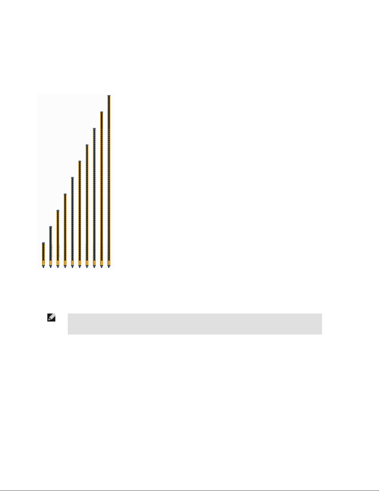
• An optoelectronic safeguarding device
• Creates a screen of synchronized, modulated infrared sensing beams. Choose from 10
sizes, in 150 mm (6") increments: defined areas from 150 mm to 1.8 m (6" to 71")
• Compact package for smaller production machines
• Models available with Trip or Latch output operation (automatic or manual start/restart)
• 30 mm (1.18") resolution
• Remote Test input terminals for simulating a "blocked" condition
• Operating range up to 15 m (50')
• Type 2 per IEC 61496-1/-2; Category 2 PLd per EN ISO 13849-1
• FMEA tested according to IEC 61496-1, Type 2 requirements
• Receiver LEDs provide system status and emitter/receiver alignment indications
• Highly immune to EMI, RFI, ambient light, weld flash, and strobe light
• Two-piece design
• Vibration-tolerant, factory burned-in emitter and receiver circuitry for toughness and dependability
System Description
NOTE: A “System” as referred to in this manual may be defined as an emitter and its receiver, plus their ca-
bling.
Banner EZ-SCREEN Type 2 emitters and receivers provide a redundant, microprocessor-controlled, opposed-mode optoelectronic "curtain of light," or "light screen." EZ-SCREEN Type 2 typically is used for point-of-operation safeguarding, and is suited to safeguard a
variety of lower-risk machinery.
The EZ-SCREEN Type 2 is a two-piece (“two-box”) system – comprising an emitter and a receiver, but no external controller. The external device monitoring (EDM) function ensures the fault detection capability required by EN ISO 13849-1 Category 2.
The EZ-SCREEN Type 2 emitters have a row of synchronized modulated infrared (invisible) light-emitting diodes (LEDs) in a compact
metal housing. Receivers have a corresponding row of synchronized photodetectors. The light screen created by the emitter and receiver
is called the “defined area”; its width and height are determined by the length of the sensor pair and the distance between them. The lowprofile housing provides maximum sensing within minimum space; its defined area (sensing area) is equivalent to the height of the housing. The maximum range is 15 m (50'), which decreases if corner mirrors are used. Resolution is 30 mm (1.18")..
Both emitter and receiver feature LEDs to provide continuous indication of the System’s operating status, alignment and error conditions.
122452 rev. B
www.bannerengineering.com - tel: 763-544-3164 5
Page 6
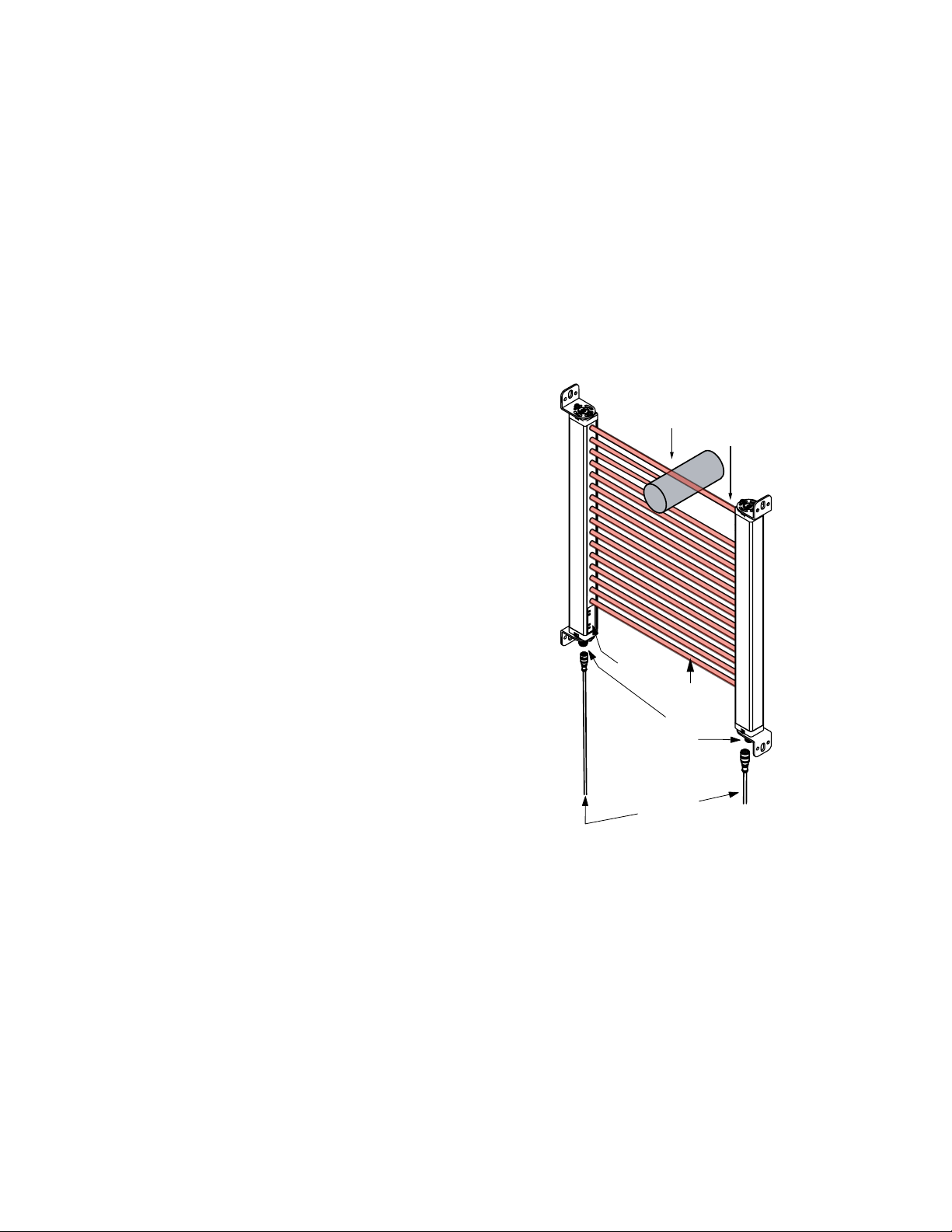
Quick-Disconnect
Cables
M12 QD
Fittings
Defined
Area
Emitter
Specified Test Piece
Synchronization
Beam
Receiver
Status
Indicators
EZ-SCREEN® Type 2 Light Screen Instruction Manual
In typical operation, if any part of an operator’s body (or any opaque object) of more than a pre-determined cross section is detected, the
solid-state Output Signal Switching Device (OSSD) safety outputs will turn OFF. These safety outputs are connected to the guarded
machine’s Final Switching Devices (FSDs) that control the machine primary control elements (MPCEs), which immediately stop the motion of the guarded machine.
Both OSSD outputs must be connected to the machine control so that the machine’s safety-related control system interrupts the circuit or
power to the MPCEs (Machine Primary Control Elements), resulting in a non-hazardous condition. Each OSSD is capable of sourcing
0.5A at +24V dc.
The OSSD safety outputs are not capable of performing a “handshake” communication with the Muteable Safety Stop Interface (MSSI) or
Universal Safety Stop Interface (USSI) found on other Banner Engineering safety products.
EZ-SCREEN Type 2 is extensively FMEA (Failure Mode and Effects Analysis) tested to IEC 61496-1/-2 requirements. The design of the
EZ-SCREEN Type 2 has considered all single faults such that a loss of a critical safety function will result in a stop command and a
lockout condition. In the event of an accumulation of undetected faults, a remote external test (or check) is required to maintain the safety
function.
Electrical connections are made through M12 (or Euro-style) quickdisconnects. An optional hookup that provides sensor interchangeability (or “swapability”) – the ability to install either sensor at either
QD connection – is possible. Using a parallel connection (color-forcolor), the emitter cable can be connected to the receiver cable,
providing the ability to swap the emitter and receiver position, similar to a popular feature of Banner MINI-SCREEN® safety light
screens. This hookup option provides advantages during installation, wiring, and troubleshooting.
All models require a supply voltage of +24V dc ±20%.
Figure 1. Banner EZ-SCREEN Type 2: emitter, receiver, and
two interconnecting cables
6 www.bannerengineering.com - tel: 763-544-3164 122452 rev. B
Page 7
EZ-SCREEN® Type 2 Light Screen Instruction Manual
Appropriate Applications and Limitations
WARNING: Read this Section Carefully Before Installing the System
If all mounting, installation, interfacing, and checkout procedures are not followed properly, the EZSCREEN Type 2 cannot provide the protection for which it was designed. The user has the responsibility
to ensure that all local, state, and national laws, rules, codes, or regulations relating to the installation and
use of this control system in any particular application are satisfied. Extreme care should be taken to ensure that all legal requirements have been met and that all technical installation and maintenance instructions contained in this manual are followed.
The user has the sole responsibility to ensure that this EZ-SCREEN Type 2 is installed and interfaced to
the guarded machine by Qualified Persons, in accordance with this manual and applicable safety regulations.
The Banner EZ-SCREEN Type 2 is intended for lower-risk machine guarding applications and other safeguarding applications, as determined by a risk assessment. It is the user’s responsibility to verify whether the safeguarding is appropriate for the application and is
installed, as instructed by this manual, by a Qualified Person (as defined in the Glossary).
CAUTION: Install System Only on Appropriate Applications
Banner EZ-SCREEN Type 2 are for use only on machinery that can be stopped immediately after a stop
signal is issued at any point in the machine's stroke or cycle, such as part-revolution clutched machines.
Under no circumstances may the EZ-SCREEN Type 2 be used on full-revolution clutched machinery or in
unsuitable applications as those listed. If there is any doubt about whether or not your machinery is
compatible with the EZ-SCREEN Type 2, contact Banner's Application Engineers at the factory.
CAUTION: Use of EZ-SCREEN Type 2
EZ-SCREEN Type 2 meets the Type 2 requirements of IEC 61496 and Category 2 PLd requirements of
EN ISO 13849-1. DO NOT use EZ-SCREEN Type 2 unless it is installed, tested, and inspected in accordance with this manual. DO NOT use EZ-SCREEN Type 2 where Control Reliability is required, or where
Category 3, Category 4, or Type 4 AOPD (active opto-electronic protective device) have been mandated,
or where a risk assessment has determined that frequent access by personnel to the hazard could result
in an irreversible or serious injury (for example, OSHA reportable injury).
Typical use is for safeguarding in situations where the consequence of an accident will result in only slight
(normally reversible) injuries that are typically treated by the normal healing processes and minor medical
treatment (that is, first aid, as defined by OSHA 29CFR1904.7).
Failure to follow these instructions could result in serious bodily injury or death.
122452 rev. B www.bannerengineering.com - tel: 763-544-3164 7
Page 8

EZ-SCREEN® Type 2 Light Screen Instruction Manual
Examples: Appropriate Applications
EZ-SCREEN Type 2 are typically used, but is not limited to, the following applications (dependent on machine risk assessment):
• Small assembly equipment
• Automated production equipment
• "Table-top" robotic work cells
• Component insertion/"pick-and-place" machines
• Small packaging machines
• Equipment and process protection (non-personnel safety
• Applications that could result in only slight (normally reversible) injuries (such as bump, bruise, knock-down, trapping but not crushing, minor cuts and abrasions, etc.)
Examples: Inappropriate Applications
EZ-SCREEN Type 2 may NOT be used with the following machinery or inappropriate applications:
• As a primary safeguard in frequently accessed hazardous situations that could result in serious injuries (normally irreversible, including death).
• In any case where Control Reliability, Category 3, Category 4, or Type 4 AOPD (active opto-electronic protective device) have been
mandated. See EN ISO 13849-1, IEC 61496-1, or other appropriate standard.
• Any machine that cannot be stopped immediately after a stop signal is issued, such as single-stroke (or “full-revolution”) clutched
machinery.
• Any machine with inadequate or inconsistent machine response time and stopping performance.
• Any machine that ejects materials or component parts through the defined area.
• In any environment that is likely to adversely affect photoelectric sensing efficiency. For example, corrosive chemicals or fluids or
unusually severe levels of smoke or dust, if not controlled, may degrade sensing efficiency.
• As a tripping device to initiate or reinitiate machine motion (PSDI applications), unless the machine and its control system fully comply
with the relevant standard or regulation (see ISO 12100-2, IEC 60204-1, IEC 61496-1, or other appropriate standard).
If an EZ-SCREEN Type 2 is installed for use as a perimeter guard (that is, where a pass-through hazard may exist), the dangerous
machine motion can be initiated by normal means only after the safeguarded area is clear of individuals and the EZ-SCREEN Type 2 has
been manually reset.
Control Reliability and Safety Categories
To summarize the expected safety circuit performance in high-risk situations, requirements of Control Reliability (OSHA 29CFR1910.217,
ANSI B11.19, and ANSI/RIA R15.06) and Category 3 and Category 4 (EN ISO 13849-1) demand that a reasonably foreseeable, single
failure does not lead to the loss of the safety function, and does not prevent a normal or immediate stop from occurring. The failure or the
fault must be detected at or before the next demand of safety (e.g., at the beginning or end of a cycle, or when a safeguard is actuated).
The safety-related part of the control system then must issue an immediate stop command, or prevent the next machine cycle or hazardous situation until the failure or fault is corrected.
The effect of ANSI/RIA R15.06, ANSI B11.19, and EN ISO 13849-1 is to set a baseline for situations in which a minimum level of performance has been mandated or in cases where a risk assessment has determined a need for Control Reliability, Category 3 or Category
4 level of performance.
In lower-risk safety applications, safeguards and safety circuits do not require the level of performance and fault tolerance described by
Control Reliability, Category 3 or Category 4. Applications involving situations that could result in a slight or normally reversible injury
(e.g., only requiring first aid, as defined by OSHA 29CFR1904) can be solved by EN ISO 13849-1 Category 2.
EN ISO 13849-1 Category 2 does not require the same level of performance and fault tolerance as required by Control Reliability, Category 3 or Category 4. Safety-related parts of control systems designed to Category 2 “shall be designed so that their function(s) are
checked at suitable intervals by the machine control system.” This allows a single fault to lead to the loss of the safety function between
the check [test] of the system, but the loss of safety function is detected by the check. By comparison, in a system designed to EN ISO
13849-1 Category 4, a single fault or an accumulation of faults will not lead to a loss of the safety function.
While EN ISO 13849-1 generally applies to the machine level, IEC61496-1/-2 specifies requirements for the design, construction and
testing for two levels or “types” of active opto-electronic protective devices (AOPDs) or light curtains (light screens). “Type 2” and “Type
8 www.bannerengineering.com - tel: 763-544-3164 122452 rev. B
Page 9

EZ-SCREEN® Type 2 Light Screen Instruction Manual
4” describe differing requirements to ensure that appropriate safety-related performance is achieved. The appropriate type is dependent
on the overall degree of risk reduction, as determined by the machine’s Risk Assessment (see ISO 14121, ANSI B11.19, ANSI/RIA
R15.06).
A Type 2 AOPD relies on periodic testing to detect a failure to danger. Between tests, a single fault can result in the loss of the safety
function. While this level of performance and fault tolerance is generally not allowed in Category 4 situations, it is acceptable in the lowerrisk situations described by Category 2.
While the EZ-SCREEN Type 2 conducts continual internal self-tests and all single faults have been considered, the installation should
provide an additional periodic test/check of the EZ-SCREEN Type 2 and its interface to ensure the integrity of the safety function (see
Manual Reset/Remote Test Input and EDM on page 36). A component failure detected by periodic test/check must cause a “stop”
signal to be sent to the guarded machine and put the System into a Lockout condition.
Recovery from this type of Lockout condition requires:
• Replacement of the failed component (to restore the safety function)
• The appropriate reset procedure.
Operating Features
The Banner EZ-SCREEN Type 2 Light Screen models described by this manual feature standard selectable functions:
• Trip or Latch Output (depending on model)
• External Device Monitoring (EDM) via the Test/Retest input
The System Response Time (Tr) can be determined by the model number on the emitter and receiver.
Trip/Latch Output
Whether a receiver features Trip or Latch Output determines whether the System will enter RUN mode automatically after power-up, or if
it will require a manual reset first. If the System has Trip Output, other measures must be taken to prevent a pass-through hazard.
For Latch Output models, the EZ-SCREENEZ-SCREENEZ-SCREEN Type 2 requires a manual reset for the OSSD outputs to turn ON,
after power is applied and all beams are clear.
• For Trip Output models, the OSSD outputs will turn ON after power is applied and the receiver passes its internal self-test/synchronization and recognizes that all beams are clear. Trip Output models will also automatically reset after all beams are cleared.
• For Latch Output models, the EZ-SCREEN Type 2 requires a manual reset for the OSSD outputs to turn ON, whenever power is
applied and all beams are clear.
WARNING: Use of Trip/Latch Output
Application of power to the EZ-SCREEN Type 2, the clearing of the defined area, or the reset of a Latch
condition MUST NOT initiate dangerous machine motion. Machine control circuitry must be designed so
that one or more initiation devices must be engaged (i.e., a conscious act) to start the machine – in addition to the EZ-SCREEN Type 2 going into RUN mode. Failure to follow these instructions could result in an
increased risk of harm.
122452 rev. B www.bannerengineering.com - tel: 763-544-3164 9
Page 10

D
C
A
B
EZ-SCREEN® Type 2 Light Screen Instruction Manual
Wiring Options for Emitter/Receiver Swapability
Each EZ-SCREEN Type 2 sensor can be connected to its own power supply or, color-for-color to the other sensor’s cable. The color-forcolor hookup allows the emitter and receiver positions to be interchanged without rewiring (functionality known as sensor " swapability").
Model CSB.. splitter cordsets and DEE2R.. double-ended cables facilitate interconnection between an EZ-SCREEN Type 2 receiver and
emitter, providing a single "homerun" cable for optional swapable hookup.
Individual Cordsets Splitter Cordsets
EZ-SCREEN Type 2
A
Key Description
C
Bn
Or/Bk
Or
Wh
Bk
Bu
Gn/Ye
Vi
B
+24V dc
n.c.
n.c.
OSSD2
OSSD1
0V dc
Ground
Reset/Test & EDM
Key Description
A Emitter
B Receiver
C QDE-8..D Cordsets
A Emitter
B Receiver
C DEE2R.. Cordsets
D CSB.. Cordsets
Manual Reset/Remote Test Input and EDM
A single input provides the means to reset the system from a latch or lockout condition, to externally test the light screen and its interface,
and to monitor external devices (EDM) for proper operation. If the System is in Run condition with outputs ON, operating the switch
results in a test. If the System is Latched or Locked Out, operating the switch results in a reset.
10 www.bannerengineering.com - tel: 763-544-3164 122452 rev. B
Page 11
Power/Fault LED (Green)
Alignment LEDs
(Yellow)
Status Blocked LED (Red)
Status Clear LED (Green)
EZ-SCREEN® Type 2 Light Screen Instruction Manual
External Device Monitoring (EDM)
This feature allows the EZ-SCREEN Type 2 system to monitor the status of external devices such as MPCEs. The EDM used in this
system is similar to Power Monitoring employed by MINI-SCREEN safety light screens. A normally closed and a normally open contact
from each monitored device are wired in series-parallel to detect if one of the devices fails.
Status Indicators
Status indicators on both the emitter and receiver are clearly visible on each sensor’s front panel.
Figure 2. EZ-SCREEN Type 2 emitter and receiver status indicators
122452 rev. B www.bannerengineering.com - tel: 763-544-3164 11
Page 12

EZ-SCREEN® Type 2 Light Screen Instruction Manual
Mechanical Installation
The effective use of the EZ-SCREEN Type 2 as a safety guarding device depends on two things:
• the suitability of the application
• the proper mechanical and electrical installation and interfacing to the guarded machine.
WARNING: Read this Section Carefully Before Installing the System
If all mounting, installation, interfacing, and checkout procedures are not followed properly, the EZSCREEN Type 2 cannot provide the protection for which it was designed. The user has the responsibility
to ensure that all local, state, and national laws, rules, codes, or regulations relating to the installation and
use of this control system in any particular application are satisfied. Extreme care should be taken to ensure that all legal requirements have been met and that all technical installation and maintenance instructions contained in this manual are followed.
The user has the sole responsibility to ensure that this EZ-SCREEN Type 2 is installed and interfaced to
the guarded machine by Qualified Persons, in accordance with this manual and applicable safety regulations.
This section has two main subsections:
• Considerations in designing the layout of the application
• Mounting the hardware
Pre-Installation Considerations
This subsection describes important considerations before you begin installing the EZ-SCREEN Type 2. The two primary factors that
influence the layout of the EZ-SCREEN Type 2 System’s mechanical installation the most are the Safety Distance (See Calculating the
Safety Distance (Minimum Distance) on page 13) and eliminating pass-through hazards (see Reducing or Eliminating Pass-Through
Hazards on page 17). Additionally, you will find information on the following in this section:
• Emitter and receiver orientation (see Emitter and Receiver Orientation on page 21)
• Dealing with the affects of adjacent reflective surfaces (see Adjacent Reflective Surfaces on page 19)
• Using corner mirrors (see Use of Corner Mirrors on page 20)
• Installing multiple systems (see Installation of Multiple Systems on page 21)
12 www.bannerengineering.com - tel: 763-544-3164 122452 rev. B
Page 13
D
EZ-SCREEN
® Type 2 Light Screen Instruction Manual
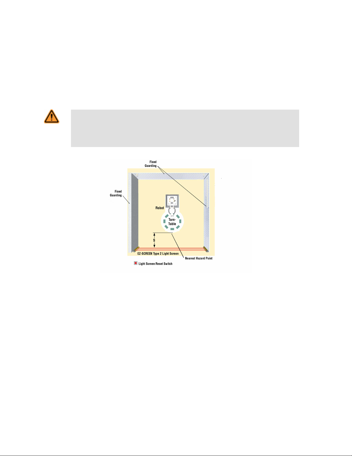
Calculating the Safety Distance (Minimum Distance)
Safety Distance (Ds), also called Minimum Distance (S), is the minimum distance required between the defined area and the closest
reachable hazard point. The distance is calculated so that when an object or a person is detected (by blocking a sensing beam), the EZSCREEN Type 2 will send a stop signal to the machine, causing it to stop by the time the person can reach any machine hazard point.
The distance is calculated differently for domestic U.S. and European installations. Both methods take into account several factors, including a calculated human speed, the total system stopping time (which itself has several components), and the depth penetration factor. After the distance has been determined, record the calculated distance on the Daily Checkout Card
WARNING: Proper Safety Distance
Banner EZ-SCREEN Type 2 emitters and receivers must be mounted at a distance from the nearest hazard such that an individual cannot reach the hazard before cessation of hazardous motion or situation.
Failure to establish and maintain the minimum distance could result in increased risk of harm.
Figure 3. Safety distance and hard guarding
122452 rev. B www.bannerengineering.com - tel: 763-544-3164 13
Page 14
EZ-SCREEN® Type 2 Light Screen Instruction Manual
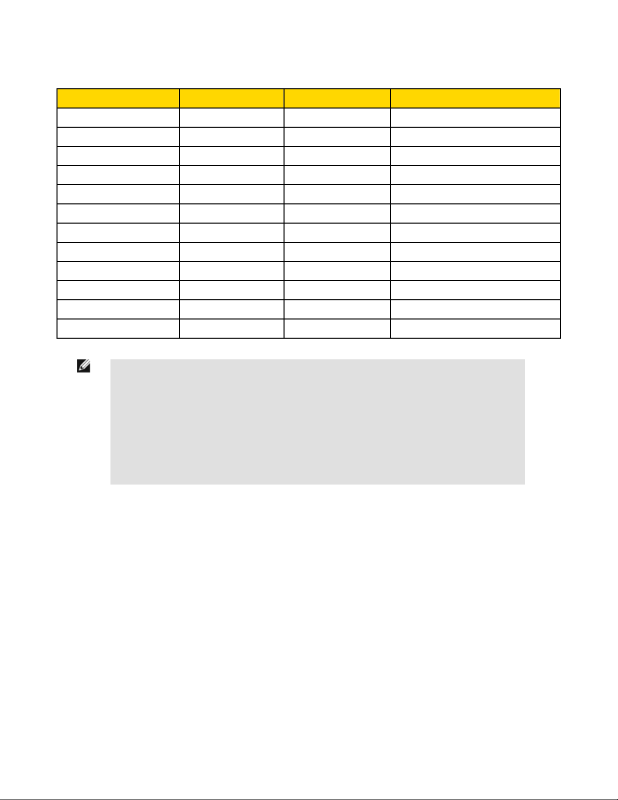
EZ-SCREEN Type 2 Models With Response Times
Models (see note below) Defined Area Height Number of Beams Response Time (Tr)
LS2..30-150Q8 150 mm (5.9") 8 11 ms
LS2..30-300Q8 300 mm (11.8") 16 13 ms
LS2..30-450Q8 450 mm (17.7") 24 14 ms
LS2..30-600Q8 600 mm (23.6") 32 16 ms
LS2..30-750Q8 750 mm (29.5") 40 17 ms
LS2..30-900Q8 900 mm (35.4") 48 19 ms
LS2..30-1050Q8 1050 mm (41.3") 56 21 ms
LS2..30-1200Q8 1200 mm (47.2") 64 22 ms
LS2..30-1350Q8 1350 mm (53.1") 72 24 ms
LS2..30-1500Q8 1500 mm (59") 80 25 ms
LS2..30-1650Q8 1650 mm (65") 88 27 ms
LS2..30-1800Q8 1800 mm (70.9") 96 29 ms
NOTE: The .. in the model numbers is one of the following:
• E = Emitter
• TR = Trip-Output Receiver
• LR = Latch-Output Receiver
• TP = Trip-Output Emitter/Receiver Pair
• LP = Latch-Output Emitter/Receiver Pair
Pair model numbers end in 88 (for example, LS2TP30-150Q88) to indicate that both the transmitter and receiver have an 8-pin connector.
14 www.bannerengineering.com - tel: 763-544-3164 122452 rev. B
Page 15

EZ-SCREEN
® Type 2 Light Screen Instruction Manual
Formula and Examples
The Safety (separation) distance formula for U.S. applications:
Ds = K x (Ts + Tr) + Dpf
The minimum distance formula for European applications:
S = (K x T) + C
where:
U.S. Applications
Ds
the safety distance, in mm (inches).
K
1600 mm per second (or 63" per second), the
OSHA 29CFR1910.217, ANSI B11.19, ANSI/RIA
R15.06 recommended hand-speed constant
(See Note 1 below)
Ts
the overall stop time of the machine (in seconds)
from the initial “stop” signal to the final ceasing of
all motion, including stop times of all relevant
control elements (e.g., IM-T-.. Interface Modules)
and measured at maximum machine velocity
(See Note 3 below).
Tr
the maximum response time, in seconds, of the
EZ-SCREEN Type 2 emitter/receiver pair (depending on model).
Dpf
the added distance – in this case, 78 mm (3") –
due to depth penetration factor as prescribed in
OSHA 29CFR1910.217, ANSI B11.19, ANSI/RIA
R15.06 for U.S. applications .
European Applications
S
the minimum distance, in mm, from danger zone
to light screen center line; minimum allowable
distance is 100 mm ( 175 mm for non-industrial
applications), regardless of calculated value.
K
hand-speed constant (see Note 2); 2000 mm/s
(for minimum safety distances < 500 mm) 1600
mm/s (for minimum safety distances > 500 mm)
T
the overall machine stopping response time (in
seconds), from the physical initiation of the safety
device and the machine coming to a stop (or the
hazard removed). This can be broken down into
two parts: Ts and Tr where T = Ts + Tr
C
the additional distance, in mm, based on intrusion of hand or object towards danger zone prior
to actuation of a safety device.
Calculate using the formula:
C = 8 x (d - 14)
where d is the resolution of the light curtain (for d
< 40 mm). For EZ-SCREEN Type 2, d = 30 mm
and C = 128 mm (5").
Notes:
1. The OSHA-recommended hand speed constant K has been determined by various studies and, although these
studies indicate speeds of 1600 mm/sec. (63"/sec.) to more than 2500 mm/sec. (100"/sec.), they are not conclusive determinations. Consider all factors, including the physical ability of the operator, when determining the value
of K to be used.
2. The recommended hand speed constant K, derived from data on approach speeds of the body or parts of the
body as stated in ISO 13855.
3. Ts is usually measured by a stop-time measuring device. If the machine manufacturer's specified stop time is
used, at least 20% should be added to allow for possible clutch/ brake system deterioration. This measurement
must take into account the slower of the two MPCE channels, and the response time of all devices or controls
that react to stop the machine. See Notice Regarding MPCEs. If all devices are not included, the calculated separation distance (Ds) will be too short and serious injury could result.
122452 rev. B www.bannerengineering.com - tel: 763-544-3164 15
Page 16

EZ-SCREEN® Type 2 Light Screen Instruction Manual
Examples
Example: U.S. Applications, Model LS2..30-600
K = 63" per second (the hand speed constant set by
OSHA)
Ts = 0.32 (0.250 second is specified by the machine
manufacturer; plus 20% safety factor; plus 20 ms
for interface module IM-T-9A response)
Tr = 0.016 second (the specified response time of an
LS2..30-600 EZ-SCREEN Type 2)
Dpf = 3"
Substitute the numbers into the formula as follows:
Ds = K x ( Ts + Tr ) + Dpf
Ds = 63 x (0.32 + 0.016) + 3 = 24.2"
Mount the EZ-SCREEN Type 2 emitter and receiver so that no
part of the defined area will be closer than 24.2" to the closest
reachable hazard point on the guarded machine.
WARNING: Determine Correct Stop Time
Example: European Applications, Model LS2..30-600
K = 1600 mm per second
T = 0.336 (0.250 second specified by machine manufac-
turer; plus 20% safety factor; plus 20 ms interface
module response), plus 0.016 second (the specified
LS2..30-600 response time)
C = 8 x (30-14) = 128 mm
Substitute the numbers into the formula as follows:
S = (K x T ) + C
S = (1600 x 0.336) + 128 = 665.6 mm
Mount the EZ-SCREEN Type 2 emitter and receiver so that no
part of the defined area will be closer than 665.6 mm to the closest reachable hazard point on the guarded machine.
Stop time (Ts) must include the response time of all devices or controls that react to stop the machine. If all devices are not included, the calculated safety distance (Ds) will be too short. This can lead to
an increased risk of harm. Be sure to include the stop time of all relevant devices and controls in your
calculations.
If required, each of the two Machine Primary Control Elements (MPCE1 and MPCE2) must be capable of
immediately stopping the dangerous machine motion, regardless of the state of the other. These two channels of machine control need not be identical, but the stop time performance of the machine (Ts, used to
calculate the safety distance) must take into account the slower of the two channels.
16 www.bannerengineering.com - tel: 763-544-3164 122452 rev. B
Page 17
EZ-SCREEN® Type 2 Light Screen Instruction Manual
Reducing or Eliminating Pass-Through Hazards
A pass-through hazard is associated with applications where personnel may pass through a safeguard (which issues a stop command to
remove the hazard), and then continues into the guarded area, such as in perimeter guarding. Subsequently, their presence is no longer
detected, and the related danger becomes the unexpected start or restart of the machine while personnel are within the guarded area.
In the use of light screens, a pass-through hazard typically results from large safety distances calculated from long stopping times, large
minimum object sensitivities, reach-over, reach-through, or other installation considerations. A pass-through hazard can be generated
with as little as 75 mm (3") between the defined area and the machine frame or hard guarding.
Eliminate or reduce pass-through hazards whenever possible. While it is recommended to eliminate the pass-through hazard altogether,
this may not be possible due to machine layout, machine capabilities, or other application considerations.
One solution is to ensure that personnel are continually sensed while within the hazardous area. This can be accomplished by using
supplemental safeguarding, such as described by the ANSI B11.19 of safety requirements or other appropriate standards.
An alternate method is to ensure that once the safeguarding device is tripped it will latch, and will require a deliberate manual action to
reset. This method of safeguarding relies upon the location of the reset switch as well as safe work practices and procedures to prevent
an unexpected start or restart of the guarded machine.
WARNING: Use of EZ-SCREEN Type 2 for Perimeter Guarding
If an EZ-SCREEN Type 2 is installed in an application that results in a pass-through hazard (e.g., perimeter guarding), either the EZ-SCREEN Type 2 System or the Machine Primary Control Elements (MPCEs)
of the guarded machine must cause a Latched response following an interruption of the defined area.
The reset of this Latched condition may only be achieved by actuating a reset switch that is separate from
the normal means of machine cycle initiation.
Lockout/Tagout procedures per ANSI Z244.1 may be required, or additional safeguarding, as described by
ANSI B11.19 safety requirements or other appropriate standards, must be used if a passthrough hazard
can not be eliminated or reduced to an acceptable level of risk. Failure to observe this warning could
result in an increased risk of harm.
Supplemental Safeguarding
As described in Calculating the Safety Distance (Minimum Dis-
tance) on page 13, the EZ-SCREEN Type 2 must be properly posi-
tioned such that an individual can not reach through the defined
area and access the hazard point before the machine has stopped.
Additionally, the hazard can not be accessible by reaching around,
under, or over the defined area. To accomplish this, supplemental
guarding (mechanical barriers, such as screens or bars), as described by ANSI B11.19 safety requirements or other appropriate
standards, must be installed. Access will then be possible only
through the defined area of the EZ-SCREEN Type 2 System or
through other safeguarding that prevents access to the hazard
(see Figure 4. An example of supplemental safeguarding on page
17).
The mechanical barriers used for this purpose are typically called
"hard guarding'; there must be no gaps between the hard guarding
and the defined area. Any openings in the hard guarding must
comply with the safe opening requirements of ANSI B11.19 or other appropriate standard.
122452 rev. B www.bannerengineering.com - tel: 763-544-3164 17
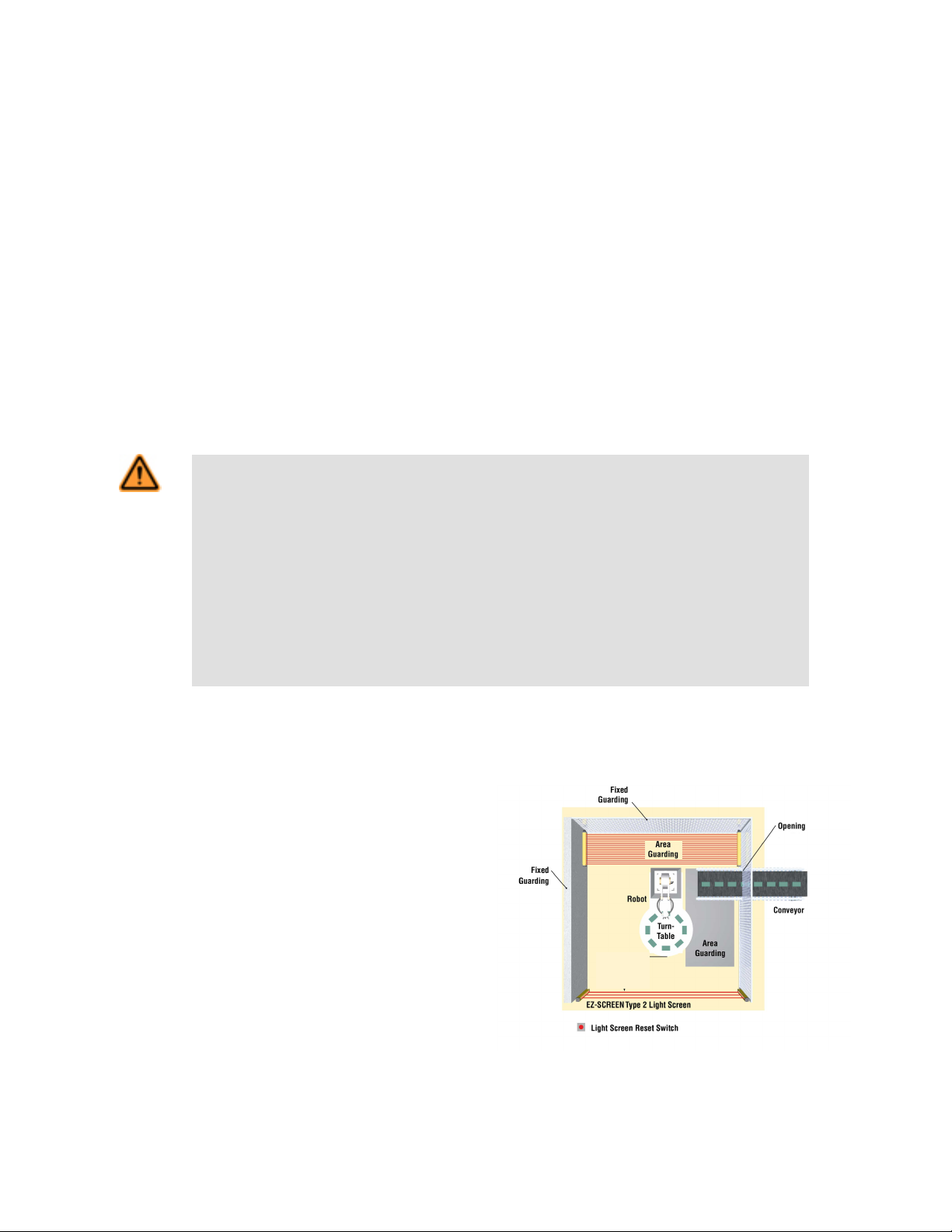
Figure 4. An example of supplemental safeguarding
Page 18
EZ-SCREEN® Type 2 Light Screen Instruction Manual
Figure 4. An example of supplemental safeguarding on page 17 shows an example of supplemental safeguarding inside a robotic work
cell. The EZ-SCREEN Type 2, in conjunction with the hard guarding, is the primary safeguard. Supplemental safeguarding (such as a
horizontal-mounted safety light screen as an area guard) is required in areas that can not be viewed from the reset switch (i.e., behind
the robot and the conveyor). Additional supplemental safeguarding may be required to prevent clearance or trapping hazards (for example, the safety mat as an area guard between the robot, the turntable, and the conveyor).
WARNING: The Hazard Must Be Accessible Only through the Defined Area
The installation of the EZ-SCREEN Type 2 System must prevent any individual from reaching around, under, over or through the defined area and into the hazard without being detected. Mechanical barriers (for
example, hard guarding) or supplemental safeguarding may be required to comply with this requirement,
and is described by ANSI B11.19 safety requirements or other appropriate standards.
Other Considerations
Reset Switch Location
A key-actuated reset switch provides some operator or supervisory control, as the key can be removed from the switch and taken into the
guarded area. However, this does not prevent unauthorized or inadvertent resets due to spare keys in the possession of others, or additional personnel entering the guarded area unnoticed. When considering where to locate the reset switch, follow the guidelines in the
Warning below.
WARNING: Reset Switch Location
When considering where to locate the reset switch, you must follow the guidelines outlined in this section.
If any areas within the guarded area are not visible from the reset switch, additional safeguarding must be
provided, as described by the ANSI B11.19 series or other appropriate standards.
Failure to follow these instructions could result in an increased risk of harm
All reset switches must be:
• Outside the guarded area
• Located to allow the switch operator a full, unobstructed, view of the entire guarded area while the reset is performed
• Out of reach from within the guarded area
• Protected against unauthorized or inadvertent operation (such as through the use of rings or guards).
Important: Resetting a safeguard must not initiate hazardous motion. Safe work procedures require a startup procedure to be followed and the individual performing the reset to verify that the entire hazardous area is
clear of all personnel, before each reset of the safeguard is performed. If any area can not be observed from
the reset switch location, additional supplemental safeguarding must be used: at a minimum, visual and audible warnings of machine start-up.
18 www.bannerengineering.com - tel: 763-544-3164 122452 rev. B
Page 19
d
d
d
Operating Range
(R)
Emitter Receiver
Do not position reflective surfaces
within the shaded area
top view
side view
EZ-SCREEN
® Type 2 Light Screen Instruction Manual
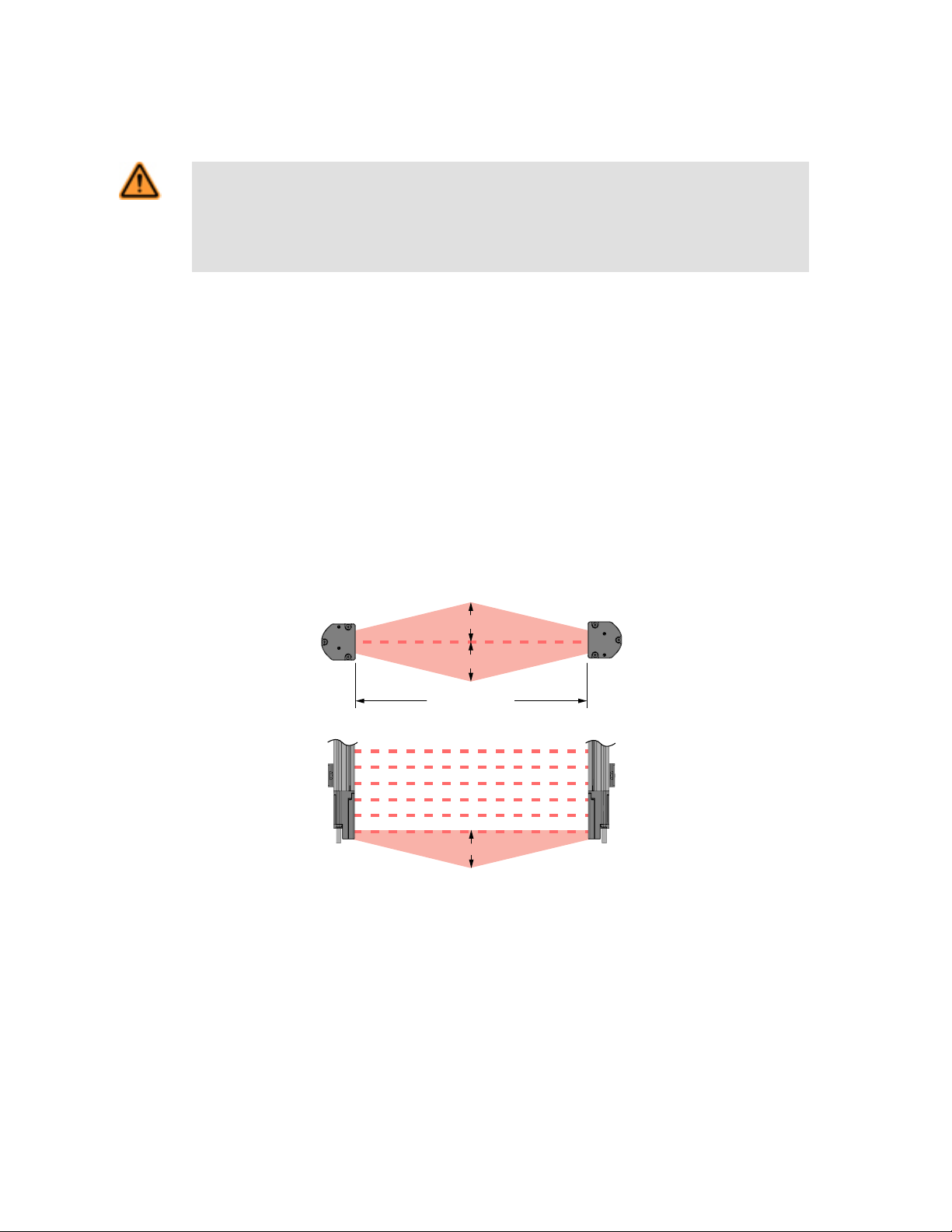
Adjacent Reflective Surfaces
WARNING: Avoid Installation Near Reflective Surfaces
Avoid locating the defined area near a reflective surface; it could reflect sensing beam(s) around an object
or person within the defined area, and prevent its detection by the EZ-SCREEN Type 2.
Reflections will result in incomplete guarding and could result in an increased risk of harm.
A reflective surface located adjacent to the defined area may deflect one or more beams around an object in the defined area. In the
worst case, an optical short circuit may occur, allowing an object to pass undetected through the defined area.
This reflective surface may result from shiny surfaces or glossy paint on the machine, the workpiece, the work surface, the floor or the
walls. Beams deflected by reflective surfaces are discovered by performing the trip test and the periodic checkout procedures. To eliminate problem reflections:
• If possible, relocate the sensors to move the beams away from the reflective surface(s), being careful to maintain adequate separation distance.
• Otherwise, if possible, paint, mask or roughen the shiny surface to reduce its reflectivity.
• Where these are not possible (as with a shiny workpiece), mount the sensors in such a way that the receiver's field of view and/or the
emitter's spread of light are restricted.
• Repeat the trip test (see Trip Test on page 32) to verify that these changes have eliminated the problem reflection(s). If the workpiece is especially reflective and comes close to the defined area, perform the trip test with the workpiece in place.
122452 rev. B www.bannerengineering.com - tel: 763-544-3164 19
For 0.2 to 3 m (8" to 10') Operating range: d = 0.26 m (10")
For Operating range > 3 m (> 10'): d = 0.0875 x R (m or ft)
Figure 5. Adjacent reflective surfaces
Page 20
Recommended sensor
configuration angle
Emitter
Emitter
Receiver
Receiver
Mirror Mirror
A
45° < A < 120°
EZ-SCREEN® Type 2 Light Screen Instruction Manual
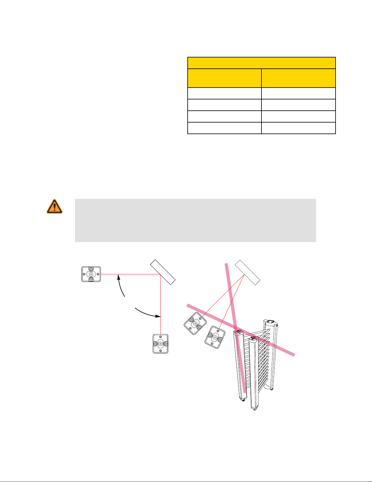
Use of Corner Mirrors
EZ-SCREEN Type 2 Systems may be used with one or more cor-
SSM and MSM Series Glass-Surface Mirrors
ner mirrors. The use of glass-surface corner mirrors reduces the
maximum specified emitter/receiver separation by approximately 8
percent per mirror, as follows:
Corner Mirrors Max. Emitter / Receiver
Range
1 13.8 m (45')
2 12.7 m (42')
3 11.7 m (38')
4 10.8 m (35')
Mirrors are not allowed for applications that would allow personnel undetected access into the safeguarded area.
If mirrors are used, the difference between the angle of incidence from the emitter to the mirror and from the mirror to the receiver must
be between 45° and 120°. If placed at a sharper angle, as shown in the example, an object in the light screen may deflect beam(s) to the
receiver, preventing the object from being detected (that is, "false proxing"). Angles greater than 120° result in difficult alignment and
possible optical short circuits.
WARNING: Avoid Retroreflective Installation
Do not install emitters and receivers in "retroreflective" mode, with less than a 45° angle of incidence, as
shown.
Sensing could be unreliable in this configuration; an increased risk of harm could result.
20 www.bannerengineering.com - tel: 763-544-3164 122452 rev. B
Figure 6. Never use EZ-SCREEN Type 2 sensors in a retroflective mode.
Page 21
Receiver
Emitter
Receiver
Emitter
Receiver
Emitter
Receiver
Emitter
Receiver
Emitter
EZ-SCREEN
® Type 2 Light Screen Instruction Manual
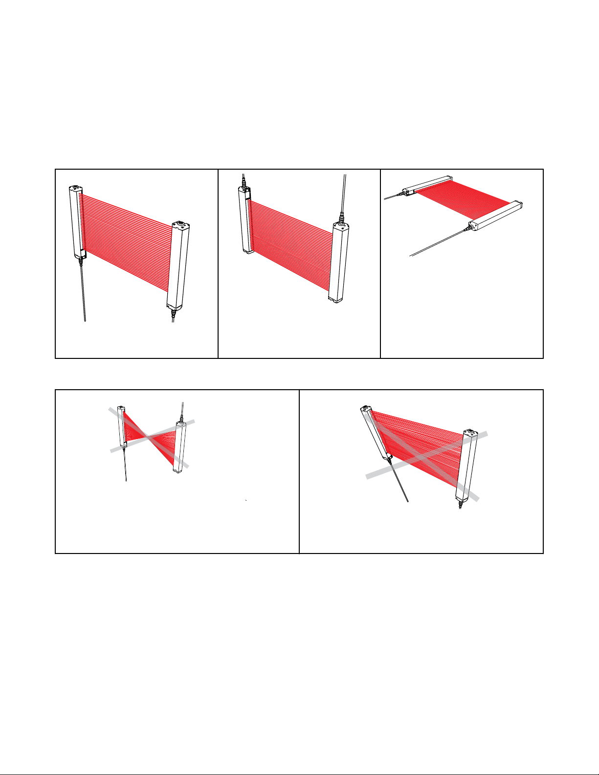
Emitter and Receiver Orientation
The emitter and receiver must be mounted parallel to each other and aligned in a common plane, with both cable ends pointing in the
same direction. Never mount the emitter with its cable end oriented opposite the cable end of the receiver. If this occurs, voids in the light
screen may allow objects or personnel to pass through the defined area undetected.
The emitter and receiver may be oriented in a vertical or horizontal plane, or at any angle between horizontal and vertical, as long as they
are parallel and their cable ends point in the same direction. Verify that the light screen completely covers all access to the hazard point
that is not already protected by hard guarding or other supplemental guarding.
a) Both cable ends down. b) Both cable ends up. c) Orientation parallel to floor with both ca-
ble ends pointing in the same direction.
Figure 7. Examples of Correct Emitter/Receiver Orientation
a) Cable ends point in opposite directions.
Problem: Voids in defined area
b) Emitter and receiver not parallel to each other.
Problem: Reduced excess gain
Figure 8. Examples of incorrect Emitter/Receiver Orientation
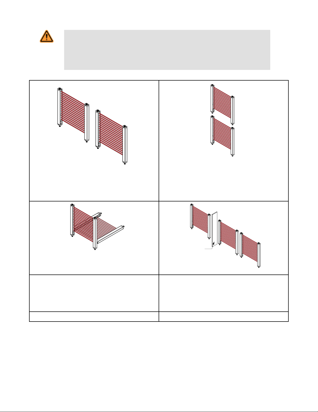
Installation of Multiple Systems
Whenever two or more EZ-SCREEN Type 2 emitter and receiver pairs are adjacent to one another, optical crosstalk may potentially take
place between systems. To minimize optical crosstalk, alternate the positions of emitters and receivers, (see Figure 9. Installation of
multiple systems on page 22).
When two or more systems are installed in the same plane (as shown in Figure 9. Installation of multiple systems on page 22), optical
crosstalk may occur between sensor pairs whose emitter and receiver lenses are oriented in the same direction. In this situation, eliminate optical crosstalk by mounting these sensor pairs exactly in line with each other within one plane, or by adding a mechanical barrier
between the pairs.
122452 rev. B www.bannerengineering.com - tel: 763-544-3164 21
Page 22
R
E
R
E
R2
E2
R1
E1
R 3
E 3
R 1
E1
R2
E 2
A
EZ-SCREEN® Type 2 Light Screen Instruction Manual
WARNING: Proper Orientation of System Emitters and Receivers
EZ-SCREEN Type 2 System emitters and receivers must be installed with their corresponding cabled
ends pointing in the same direction (for example, both cabled ends facing up). Failure to orient them properly will impair the performance of the EZ-SCREEN Type 2 System and will result in incomplete guarding,
and could result in an increased risk of harm.
E
R
R
E
E = Emitter R = Receiver E = Emitter R = Receiver
a. Two systems in a horizontal plane b. Two or three systems stacked (or alternate receiver/emitter po-
sitions)
E1 = Vertical Emitter E2 = Horizontal Emitter
R1 = Vertical Receiver R2 = Horizontal Receiver
A = Opaque Shield
E1 = Emitter #1 E2 = Emitter #2 E3 = Emitter #3
R1 = Receiver #1 R2 = Receiver #2 R3 = Receiver #3
c. Two systems at right angles d. Multiple systems
Figure 9. Installation of multiple systems
22 www.bannerengineering.com - tel: 763-544-3164 122452 rev. B
Page 23

EZ-SCREEN
® Type 2 Light Screen Instruction Manual
WARNING: Synchronization
In situations where multiple systems are mounted closely together, or where a secondary emitter is in view
(within ±5°), within range of an adjacent receiver; a receiver may synchronize to the signal from the wrong
emitter, reducing the safety function of the light screen.
WARNING: Multiple Pairs of Sensors
Do not connect multiple pairs of sensors to one Interface Module (for example, IM-T-9A/-11A) or otherwise
parallel OSSD outputs.
Connection of multiple OSSD safety outputs to a single device can result in an increased risk of
harm, and is prohibited.
Mounting System Components
Overview of Emitter/Receiver Mounting Hardware
Mounting Hardware
The EZ-SCREEN standard end-cap mounting bracket hardware is
supplied with each emitter and receiver. Brackets are designed to
mount directly to MSA Series stands using the hardware with the
supplied stands.
122452 rev. B www.bannerengineering.com - tel: 763-544-3164 23
Page 24

EZ-SCREEN® Type 2 Light Screen Instruction Manual
Using Center Mounting Brackets
Center mounting brackets are supplied with longer sensors and
must be used whenever the sensors are subject to shock or vibration. The sensors are designed to be mounted with up to 450 mm
(18") distance between brackets:
• Sensors 600 to 900 mm (24" to 36") long are supplied with one
center bracket, which should be centered on the sensor.
• Sensors 1050 to 1350 mm (42" to 54") long are supplied with
two center brackets, which should be positioned 1/3 of the sensor's length from each sensor end.
• Sensors 1500 to 1800 mm (59" to 71") long are supplied with
three center brackets
To install each bracket:
1. Spread the clamp and snap over the back of the sensor so
that the clamp is securely fastened to the sensor without
blocking any beams.
2. Compress the foam spacer and slide the clamp along the
length of the sensor housing to align the clamp with the center mounting bracket as shown in Figure 3-9. Three separate
mounting holes are provided on the clamp to allow for all
possible mounting configurations.
3. Connect the clamp to the center bracket using the M3 screw
supplied.
4. Loosen all the mounting screws to the sensor, align the sen-
sors and then tighten the end screws. Finally, tighten the M3
screw joining the clamp to the center mounting bracket.
Mounting and Initial Alignment of Emitter/Receiver Pairs
Emitter/receiver pairs may be spaced from 0.2 to 15 m (8" to 50') apart. The maximum distance between an emitter and its receiver is
reduced if corner mirrors are used. The supplied brackets (when mounted to the sensor end caps) allow ±30° rotation.
To mount each emitter/receiver pair:
1. From a common point of reference (ensuring the calculated safety distance), make measurements to locate the emitter and receiver in the same plane with their midpoints directly opposite each other.
Important: The connector ends of both sensors must point in the same direction (see Emitter and Re-
ceiver Orientation on page 21 ).
2. Mount the emitter and receiver mounting brackets using the supplied M6 bolts and Keps nuts, or user-supplied hardware.
3. Mount the emitter and receiver in their brackets; position their windows directly facing each other.
4. Measure from a reference plane (for example, a level building floor) to the same point(s) on the emitter and receiver to verify their
mechanical alignment.
5. Use a carpenter's level, a plumb bob, or the optional LAT-1 Laser Alignment Tool or check the diagonal distances between the
sensors, to achieve mechanical alignment.
24 www.bannerengineering.com - tel: 763-544-3164 122452 rev. B
Page 25

Level Surface
X X
Emitter Receiver
level
level
Y Y
Z
Z
Level Surface
A B
level level
XX
EZ-SCREEN® Type 2 Light Screen Instruction Manual
Verifying Initial Emitter/Receiver Alignment
As you mount the sensors, make sure that
• The emitter and receiver are directly opposite each other.
• Nothing is interrupting the defined area (marked on the sensors).
• The defined area is the same distance from a common reference plane for each sensor.
• The emitter and receiver are in the same plane and are level/plumb and square to each other (vertical, horizontal, or inclined at the
same angle).
Angled or Horizontal Installations Vertical Installations
Verify that the
• Distance X at the emitter and receiver are equal.
• Distance Y at the emitter and receiver are equal.
• Distance Z at the emitter and receiver are equal from parallel
surfaces.
• Vertical face (that is, the lens) is level/plumb.
• Defined area is square. Check diagonal measurements if
possible; see Vertical Installations, at right.
NOTE: Make sure that the emitter and
receiver are not tilted front-to-back or
side-to-side as shown.
Verify that the
• Distance X at the emitter and receiver are equal.
• Both sensors are level/plumb (check both the Distance Z at
the emitter and receiver are equal from side and face).
• Defined area is square. Check diagonal measurements if
possible (Diagonal A = Diagonal B).
122452 rev. B www.bannerengineering.com - tel: 763-544-3164 25
Page 26

EZ-SCREEN® Type 2 Light Screen Instruction Manual
Electrical Installation and Testing
As with the previous section, it is important that you read, understand and follow the electrical installation and testing procedure as described in the following subsections.
WARNING: Read this Section Carefully Before Installing the System
If all mounting, installation, interfacing, and checkout procedures are not followed properly, the EZSCREEN Type 2 cannot provide the protection for which it was designed. The user has the responsibility
to ensure that all local, state, and national laws, rules, codes, or regulations relating to the installation and
use of this control system in any particular application are satisfied. Extreme care should be taken to ensure that all legal requirements have been met and that all technical installation and maintenance instructions contained in this manual are followed.
The user has the sole responsibility to ensure that this EZ-SCREEN Type 2 is installed and interfaced to
the guarded machine by Qualified Persons, in accordance with this manual and applicable safety regulations.
There following are the main steps to electrically install the EZ-SCREEN Type 2 components and interface with the guarded machine:
1. Apply power to each emitter/receiver pair (see Initial Electrical Connections on page 27).
2. Perform and Initial Checkout Procedure (see Initial Checkout Procedure on page 28).
3. Make all electrical interface connections to the guarded machine (see Electrical Connections to the Guarded Machine on page
34).
4. Perform a commissioning checkout procedure (see Commissioning Checkout on page 38).
Routing Cordsets
Connect the QD connectors and route the sensor cables to the junction box, electrical panel, or other enclosure in which the Interface
Module, the redundant mechanically linked interposing relays, FSDs, or other safety-related parts of the control system are located. This
must be done per local wiring code for low-voltage dc control cables and may require installation of electrical conduit. See Cordsets on
page 57 for selection of Banner-supplied cordsets.
The EZ-SCREEN Type 2 is designed and manufactured to be highly resistant to electrical noise and to operate reliably in industrial
settings. However, extreme electrical noise may cause a random Trip or Latch condition; in extreme cases, a Lockout is possible. Emitter
and receiver wiring is low voltage; routing the sensor wires alongside power wires, motor/servo wires, or other high-voltage wiring may
inject noise into the EZ-SCREEN Type 2 System. It is good wiring practice (and may be required by code) to isolate emitter and receiver
cables from high-voltage wires, avoid routing cables close to “noisy” wiring, and provide a good connection to earth ground.
26 www.bannerengineering.com - tel: 763-544-3164 122452 rev. B
Page 27

EZ-SCREEN® Type 2 Light Screen Instruction Manual
Sensor QD cabling and any interconnect wiring should meet the following specifications. The wires used should have an insulation temperature rating of at least 90°C (194°F).
Maximum Machine Interface cable length versus total current draw (including both OSSD loads)
Cable Size Current Draw
0.5A 0.75A 1.0A 1.25A
0.823 mm2 (18 AWG) 375' 250' 188' 148'
0.518 mm2 (20 AWG) 240' 160' 120' 95'
0.326 mm2 (22 AWG)* 150' 100' 75' 59'
NOTE: Cable length includes power (+24V dc) and return (0V dc) wires at +25˚C, and is intended to ensure
that adequate power is available to the EZ-SCREEN Type 2 System when the supply is operating at +24V dc 10%.
Initial Electrical Connections
WARNING: Proper Electrical Hookup
Electrical hookup must be made by Qualified Personnel and must comply with NEC (National Electrical
Code) and local standards.
Connection of other wiring or equipment to the EZ-SCREEN Type 2 System could result in an increased
risk of harm.
Lockout/tagout procedures may be required (refer to OSHA1910.147, ANSI Z244-1, or the appropriate standard for controlling hazardous
energy). Following relevant electrical standards and wiring codes, such as the NEC, NFPA79 or IEC60204-1, always connect earth
ground (green/yellow wire. Do not operate the EZ-SCREEN Type 2 System without an earth ground connection.
Make the electrical connections in the order described in this section. Do not remove end-caps; no internal connections are to be made.
All connections are made through the M12 Eurostyle quick-disconnects.
Emitter Cordset Receiver Cordset
EZ-SCREEN Type 2 emitters have an 8-pin cordset, but only three
conductors are required:
• Brown = +24V dc
• Blue = 0V dc
• Green/Yellow = GND
Do not connect any wires to the machine control circuits (that
is, OSSD outputs) at this time.
For the initial checkout, only the following EZ-SCREEN Type 2 receiver conductors should be connected:
• Brown = +24V dc
• Blue = 0V dc
• Green/Yellow = GND
Additionally, connect the external reset switch, if used, or test signal contact to the Reset/Test wire (violet) and to 24V dc.
NOTE: The reset switch must be a normally closed switch that is held open for approximately 1/4 second, then
closed to accomplish the reset. The switch must be capable of switching 10 to 30V dc at 30 mA.
122452 rev. B www.bannerengineering.com - tel: 763-544-3164 27
Page 28

D
C
A
B
EZ-SCREEN® Type 2 Light Screen Instruction Manual
The other wires are for an optional hookup that allows for parallel connection (color-for-color) to the receiver cable. This optional hookup
provides for sensor interchangeability (or swapability) that facilitates installing either sensor at either QD connection. Besides providing
similar cabling, this wiring scheme is advantageous during installation, wiring, and troubleshooting.
Individual Cordsets Splitter Cordsets
EZ-SCREEN Type 2
A
Key Description
C
Bn
Or/Bk
Or
Wh
Bk
Bu
Gn/Ye
Vi
B
+24V dc
n.c.
n.c.
OSSD2
OSSD1
0V dc
Ground
Reset/Test & EDM
Key Description
A Emitter
B Receiver
C QDE-8..D Cordsets
A Emitter
B Receiver
C DEE2R.. Cordsets
D CSB.. Cordsets
Initial Checkout Procedure
The initial checkout procedure must be performed by a Qualified Person. It must be performed only after configuring the system and after
connecting the emitter and receiver.
The procedure is performed on two occasions:
• To ensure proper installation when the System is first installed
• To ensure proper System function whenever any maintenance or modification is performed on the System or on the machinery being
guarded by the System.
28 www.bannerengineering.com - tel: 763-544-3164 122452 rev. B
Page 29

EZ-SCREEN
® Type 2 Light Screen Instruction Manual
Configuring the System for Initial Checkout
For the initial checkout, the EZ-SCREEN Type 2 System must be checked without power being available to the guarded machine. Final
interface connections to the guarded machine cannot take place until the light screen system has been checked out. This may require
lockout/tagout procedures (refer to OSHA1910.147, ANSI Z244-1, or the appropriate standard for controlling hazardous energy). These
connections will be made after the initial checkout procedure has been successfully completed.
Verify that:
• Power has been removed from (or is not available to) the guarded machine, its controls or actuators; and
• The machine control circuit or the Interface Module is not connected to the OSSD outputs at this time (permanent connections will be
made later).
Initial Power-Up
Inspect the area near the light screen for reflective surfaces, including work pieces and the guarded machine. Reflective surfaces may
cause light beams to reflect around a person in the light screen, preventing the person from being detected and not stopping the machine
motion.
Eliminate the reflective surfaces as possible by relocating them, painting, masking or roughening them. Remaining problem reflections
will become apparent during the trip test.
1. Verify that power is removed from the EZ-SCREEN Type 2 System and from the guarded machine and that the OSSD safety
outputs are not connected. Remove all obstructions from the light screen.
2. Leaving power to the guarded machine OFF, make power and earth ground connections on both the emitter and receiver cables
and then power up the EZ-SCREEN Type 2 System (only).
3. Verify that input power is present to both emitter and receiver. At least one indicator on both emitter and receiver should be ON and
the start-up sequence should cycle.
122452 rev. B www.bannerengineering.com - tel: 763-544-3164 29
Page 30

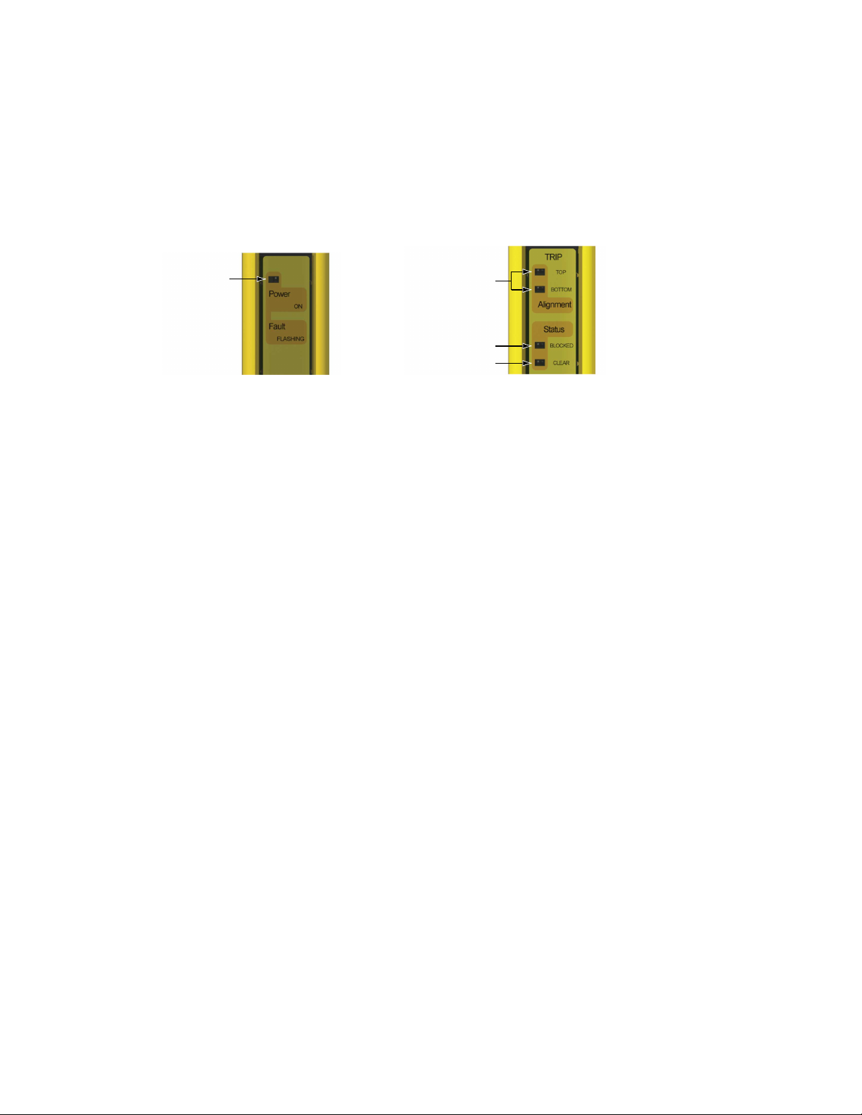
Power/Fault LED (Green)
Alignment LEDs
(Yellow)
Status Blocked LED (Red)
Status Clear LED (Green)
EZ-SCREEN® Type 2 Light Screen Instruction Manual
4. Watch both the emitter and the receiver LED indicators to determine light screen alignment status.
Figure 10. Emitter Status Indicators
Figure 11. Receiver Status Indicators
Lockout Condition
On the emitter, the green Power indicator is flashing or on the receiver, the red Status Blocked indicator is flashing. See
Troubleshooting and Lockout Conditions on page 47 for diagnostic information.
Normal Operating Mode
On the emitter, the green Power indicator is ON.
Test Mode
On the receiver, the red Status Blocked indicator is ON and the green Status Clear indicator is flashing. Test input
open.
Test Mode, input fault
On the receiver, the red Status Blocked indicator is ON and the green Status Clear indicator is ON. Test input open at
power-up.
Latch Condition, all optical beams clear
On the receiver, the red Status Blocked indicator is ON and both yellow Alignment indicators are flashing. For Latch
Output receivers, the outputs are ON only when all beams are clear and after a manual reset. If a reset routine can
cause a Clear (Run) condition, optimize the alignment as described in Optical Alignment on page 31. If a Clear (Run)
condition can not be achieved, see “Blocked condition” below.
Clear (Run) Condition
On the receiver, the green Status Clear indicator is ON Green, and both yellow Alignment indicators are ON. To optimize alignment and maximize excess gain, slightly loosen the four sensor mounting screws and rotate one sensor left
and right, noting the positions where the red Status Blocked indicator turns ON; repeat with the other sensor (see
Optical Alignment on page 31). Center each sensor between those two positions and tighten the end cap mounting
screws, making sure to maintain the positioning as the screws are tightened. The sensor lenses should directly face
each other. Proceed to Trip Test ( Trip Test on page 32) once optimum optical alignment is verified.
A Blocked Condition
On the receiver, the red Status Blocked indicator is ON, and both yellow Alignment indicators are ON or OFF. To remedy, perform the Optical Alignment on page 31 procedure.
30 www.bannerengineering.com - tel: 763-544-3164 122452 rev. B
Page 31

Straight Edge
Straight Edge
All OFF
ON Red
ON Red
ON Yellow
ON Green
ON Yellow
ON Yellow
EZ-SCREEN
® Type 2 Light Screen Instruction Manual
Optical Alignment
1. Verify sensor mounting.
2. Verify optimal alignment, adjusting sensor rotation with power ON:
a. Verify that the emitter and receiver are pointed squarely at each other. Use a straight edge (for example, a level) to deter-
mine the direction the sensor is facing. The sensor face must be perpendicular to the optical axis.
NOTE: At power-up, all indicators are tested (flash).
b. If the synchronization beam is not aligned, the Status Blocked indicator is Red and both Alignment indicators will be OFF.
c. If the Green Status and Yellow Alignment indicators are ON, go to step “d”. If not, rotate each sensor (one at a time) left and
right until the Status Clear indicator comes ON Green. As the sensor rotates out of alignment, the Status Blocked indicator
will come ON Red.
d. To optimize alignment, note the position where the Status Blocked indicator comes ON Red when the sensor is rotated both
left and right. Center the sensor between the two positions, and tighten the end cap mounting screws, making sure the positioning does not drift as the screws are tightened.
For situations where alignment is difficult, a LAT-1-LS Laser Alignment Tool can be used to assist or confirm alignment by
providing a visible red dot along the sensor’s optical axis.
122452 rev. B www.bannerengineering.com - tel: 763-544-3164 31
Page 32

FLASHING
Red
Component #2
(Mirror)
Component #3
(Mirror)
Component #4
(Receiver)
Component #1
(Emitter)
EZ-SCREEN® Type 2 Light Screen Instruction Manual
e. If, at any time, the Status Blocked indicator begins to flash Red, the System has entered a Lockout condition. See Trouble-
shooting and Lockout Conditions on page 47 for further information.
Optical Alignment Procedure with Mirrors
EZ-SCREEN Type 2 sensors may be used with one or more corner mirrors for guarding more than one side of an area. The MSM... and
SSM-... rear-surface glass mirrors are rated at 85% efficiency. Thus, excess gain and sensing range are reduced when using mirrors; see
Use of Corner Mirrors on page 20.
In addition to the standard optical alignment procedure, verify:
1. That the emitter, receiver, and all mirrors are level and plumb
2. The middle of the defined area and the center point of the mirrors are approximately the same distance from a common reference
point, such as the same height above a level floor. Ensure that there are equal amounts of mirror surface above and below the
defined area such that the optical beams are not passing below or above the mirror.
Figure 12. Optical alignment using the LAT-1-LS
Figure 13. Corner Mirror Alignment
During any adjustments, allow only one individual to adjust any one item at any one time.
NOTE: A LAT-1-LS Laser Alignment Tool is very helpful by providing a visible red dot along the optical
axis. See Figure 12. Optical alignment using the LAT-1-LS on page 32 and Banner Safety Applications
Trip Test
Note SA104 (P/N 57477) for further information.
After optimizing the optical alignment, perform the trip test to verify the detection capability of the EZ-SCREEN Type 2 System. This test
will also verify correct sensor orientation and identify optical short circuits. Once the installation has passed the trip test, the safety outputs may be connected and the commissioning checkout may be performed (initial installations only).
1. Use the 30 mm specified test piece supplied with the receiver.
32 www.bannerengineering.com - tel: 763-544-3164 122452 rev. B
Page 33

A
C
B
A
C
B
D
EZ-SCREEN® Type 2 Light Screen Instruction Manual
2. Verify that the System is in RUN mode with the Status Clear indicator ON steady Green. A manual reset may be required in Latch
mode.
3. Pass the specified test piece through the defined area in three paths: near the emitter, near the receiver, and midway between the
emitter and receiver.
4. During each pass, while the test piece is interrupting the defined area, verify:
• Trip Output Operation: The Status Blocked indicator must turn ON Red and remain ON for as long as the test piece remains in
the defined area (and the Status Clear indicator OFF during the same time). If not, the installation has failed the trip test. When
the test piece is removed from the defined area, the Status Clear indicator must turn ON Green and the Status Blocked indicator must go OFF.
• Latch Output Operation: The Status Blocked indicator must turn ON Red and remain ON for as long as the test piece remains
in the defined area (and the Status Clear indicator OFF during the same time). Both Yellow indicators must remain ON steady,
unless the top or bottom beam is blocked. If the top (synch) beam is blocked, both Alignment indicators will go OFF.
If the Yellow Alignment indicators begin to flash at any time while the test piece is interrupting the defined area, the installation
has failed the trip test. Check for correct sensor orientation and reflective surfaces. Do not continue until the situation is corrected. In Latch Output Operation, the Status Blocked indicator will remain ON until a manual reset is performed (both Yellow
Alignment indicators will be flashing).
5. If mirrors are used in the application: Test the defined area on each leg of the sensing path (for example, emitter to mirror, between
mirror and receiver, see Figure 15. Trip Test with corner mirror on page 33 ).
Figure 14. Trip Test
A Emitter
B Test Piece
C Receiver
A Emitter
B Mirror
C Receiver
Figure 15. Trip Test with corner mirror
D Test Piece
6. If the EZ-SCREEN Type 2 System passes all checks during the trip test, go on to EZ-SCREEN Type 2 Electrical Interface to the
Guarded Machine on page 34.
WARNING: If Trip Test Indicates a Problem
If the EZ-SCREEN Type 2 System does not respond properly to the trip test,do not attempt to use the
System.
If this occurs, the System cannot be relied on to stop dangerous machine motion when a person or object
enters the defined area.
Increased risk of harm could result.
122452 rev. B www.bannerengineering.com - tel: 763-544-3164 33
Page 34

EZ-SCREEN® Type 2 Light Screen Instruction Manual
Electrical Connections to the Guarded Machine
Make the electrical connections as described in the following sections ( OSSD Output Connections on page 34 to FSD Interfacing
Connections on page 35 as required by each individual application.
Lockout/tagout procedures may be required (refer to OSHA 1910.147, ANSI Z244-1, or the appropriate standard for controlling hazardous energy). Follow relevant electrical standards and wiring codes, such as the NEC, NFPA79 or IEC 60204-1.
Supply power and the external reset switch should already be connected. The EZ-SCREEN Type 2 must also have been aligned and
passed the Initial Checkout, as described in Initial Checkout Procedure on page 28.
The final connections to be made are:
• OSSD outputs
• FSD interfacing
• MPCE connections
OSSD Output Connections
Both the Output Signal Switching Device (OSSD) outputs must be connected to the machine control so that the machine’s safety-related
control system interrupts the circuit or power to the Machine Primary Control Element(s) (MPCE), resulting in a non-hazardous condition.
Final Switching Devices (FSDs) typically accomplish this when the OSSDs go to an OFF state.
Refer to the output specifications in Specifications and Accessories on page 52 and the warning below before making OSSD output
connections and interfacing the EZ-SCREEN Type 2 to the machine.
CAUTION: Shock Hazard
Always disconnect power from the EZ-SCREEN Type 2 and the guarded machine before making any connections or replacing any component. Use extreme caution to avoid electrical shock at all times.
34 www.bannerengineering.com - tel: 763-544-3164 122452 rev. B
Page 35

EZ-SCREEN
® Type 2 Light Screen Instruction Manual
WARNING: Interfacing of Both OSSDs
Both of the OSSD (Output Signal Switching Device) outputs must be connected to the machine control so
that the machine’s safety-related control system interrupts the circuit to the machine primary control element(s), resulting in a non-hazardous condition.
Never wire an intermediate device(s) (e.g., PLC, PES, or PC) that can fail in such a manner that there is
the loss of the safety stop command, OR in such a manner that the safety function can be suspended,
overridden, or defeated, unless accomplished with the same or greater degree of safety.
WARNING: OSSD Interfacing
To ensure proper operation, the EZ-SCREEN Type 2 output parameters and machine input parameters
must be considered when interfacing the EZ-SCREEN Type 2 OSSD outputs to machine inputs.
Machine control circuitry must be designed so that the maximum open ground leakage current must not
result in an ON condition.
Failure to properly interface the Safety Outputs to the guarded machine could result in serious
bodily injury or death.
FSD Interfacing Connections
FSDs (Final Switching Devices) can take many forms, though the most common are forced-guided, mechanically linked relays or an
interface module. The mechanical linkage between the contacts allows the device to be monitored by the External Device Monitoring
circuit for certain failures.
Depending on the application, the use of FSDs can facilitate controlling voltage and current that differs from the OSSD outputs of the EZSCREEN Type 2. FSDs can also be used to control an additional number of hazards by creating multiple safety stop circuits.
Protective Stop (Safety Stop) Circuits
A protective stop (safety stop) allows for an orderly cessation of motion for safeguarding purposes, which results in a stop of motion and
removal of power from the MPCEs (assuming this does not create additional hazards). A protective stop circuit typically comprises a
minimum of two normally open (N.O.) contacts from forced-guided, mechanically linked relays, which are monitored (through Power Monitoring) to detect certain failures in order to prevent the loss of the safety function. Such a circuit can be described as a “safe switching
point.” Typically, protective stop circuits are either single-channel, which is a series connection of at least two N.O. contacts; or dualchannel, which is a separate connection of two N.O. contacts. In either method, the safety function relies on the use of redundant contacts to control a single hazard (if one contact fails ON, the second contact will arrest the hazard and prevent the next cycle from occurring). See EZ-SCREEN Generic FSDs Wiring on page 41.
The interfacing of the protective stop circuits must be accomplished so that the safety function can not be suspended, overridden, or
defeated, unless accomplished in a manner at the same or greater degree of safety as the machine’s safety related control system that
includes the EZ-SCREEN Type 2.
The normally open safety outputs from an interface module provide a series connection of redundant contacts that form protective stop
circuits for use in either single-channel or dual-channel control. See Generic Wiring — Interface Module (2-Channel EDM, Manual Reset)
on page 42.
122452 rev. B www.bannerengineering.com - tel: 763-544-3164 35
Page 36

EZ-SCREEN® Type 2 Light Screen Instruction Manual
Dual-Channel Control
Dual-channel control provides the ability to electrically extend the safe switching point beyond the FSD contacts. With proper monitoring,
this method of interfacing is capable of detecting certain failures in the control wiring between the safety stop circuit and the MPCEs.
These failures include a short-circuit of one channel to a secondary source of energy or voltage, or the loss of the switching ability of one
of the FSD outputs. Such failures could lead to the loss of redundancy — or to a complete loss of safety, if not detected and corrected.
The possibility of a failure to the wiring increases as the physical distance between the FSD safety stop circuits and the MPCEs increase,
as the length or the routing of the interconnecting wires increases, or if the FSD safety stop circuits and the MPCEs are located in different enclosures. For this reason, dual-channel control with EDM monitoring should be used in any installation where the FSDs are located
remotely from the MPCEs.
Single-Channel Control
Single-channel control uses a series connection of FSD contacts to form a safe switching point. After this point in the machine’s safetyrelated control system, failures can occur that would result in the loss of the safety function (such as a short-circuit to a secondary source
of energy or voltage).
For this reason, single-channel control interfacing should be used only in installations where FSD safety stop circuits and the MPCEs are
mounted within the same control panel, adjacent to each other, and are directly connected to each other; or where the possibility of such
a failure can be excluded. If this can not be achieved, then dual-channel control should be used.
Methods to exclude the possibility of these failures include, but are not limited to:
• Physically separating interconnecting control wires from each other and from secondary sources of power.
• Routing interconnecting control wires in separate conduit, runs, or channels.
• Locating all elements (modules, switches, and devices under control) within one control panel, adjacent to each other, and directly
connected with short wires.
• Properly installing multi-conductor cabling and multiple wires through strain relief fittings. (Over-tightening of a strain-relief can cause
short-circuits at that point.)
• Using positive-opening or direct-drive components, installed and mounted in a positive mode.
Machine Primary Control Elements
Each of the two Machine Primary Control Elements (MPCE1 and MPCE2) must be capable of immediately stopping the dangerous machine motion, irrespective of the state of the other. These two channels of machine control need not be identical, but the stop time performance of the machine (Ts, used to calculate the safety distance, see EZ-SCREEN Calculating Safety Distance on page 13) must take
into account the slower of the two channels. Some machines offer only one Primary Control Element. For such machines, it may be
necessary to duplicate the circuit of the single MPCE, by adding a second. Refer to Generic Wiring to FSDs (manual reset) on page 41
and Generic Wiring — Interface Module (2-Channel EDM, Manual Reset) on page 42, or consult the machine manufacturer for additional information.
Manual Reset/Remote Test Input and EDM
A means is provided for the connection of an external remote test switch or contact (typically a normally open, held closed). Cycling this
switch “turns OFF” both OSSD outputs.
A single input provides the means to reset the system from a latch or lockout condition, to externally test the light screen and its interface,
and to monitor external devices (EDM) for proper operation. If the System is in Run condition with outputs ON, operating the switch
results in a test. If the System is Latched or Locked Out, operating the switch results in a reset. If this input is connected to 0V dc or left
floating, the System goes to a lockout condition on power-up. (See Troubleshooting and Lockout Conditions on page 47 for clearing
lockouts.)
Connect the receiver’s reset/test wire (pin 8) to the supply voltage (see Generic Wiring to FSDs (manual reset) on page 41 and Generic
Wiring — Interface Module (2-Channel EDM, Manual Reset) on page 42) via the reset switch. The switch should be a normally closed
(N.C.) reset switch, or contacts of the Machine Control Test circuit (typically a normally open contact held or energized closed), or the
monitoring contacts of the external device(s) being verified. One switch could be used for the Reset and Test functions, or they can be
separate switches. However, all switches should be mounted as specified for a reset switch (see Reset Switch Location on page 18).
36 www.bannerengineering.com - tel: 763-544-3164 122452 rev. B
Page 37

EZ-SCREEN
® Type 2 Light Screen Instruction Manual
Manual Reset/System Test Procedure
To operate the switch (and perform a manual reset or a system test), open the normally closed (N.C.) switch for a minimum of 1/4 second
and then close it.
Manual Reset
From a Latched or Lockout condition, operating the switch results in a manual reset. Safe work procedures must require that a start-up
procedure is followed and that the individual performing the reset of the guarding device verifies that the entire hazardous area is clear of
all personnel, before performing each reset. If any area can not be observed from the reset switch location, additional supplementary
guarding must be used: at minimum, visual and audible warnings of machine start-up.
Resetting a safe guarding device must not initiate hazardous motion.
Remote (External) Test
When in RUN mode, opening this switch for more than 1/4 second will initiate a Test cycle that turns OFF the OSSD outputs and generates an internal self-test.
• Automatic (Machine) Test: An external switch, typically a normally open contact that is held closed, is used to externally generate a
test cycle of the EZ-SCREEN Type 2 and its interface. Depending on the application this switch can be a limit-style switch, a hard
contact from a relay, or an output from the machine control logic.
• Manual Test: A normally closed (N.C.) momentary type switch used for manual reset can also be used to manually initiate a test
cycle. This remote Test input may be useful for EZ-SCREEN Type 2 System setup and to verify machine control circuit operation.
WARNING: Test Function
A machine or automatic test of the EZ-SCREEN Type 2 and its interface may be required as determined
by a risk assessment and appropriate standard (for example, ISO 14121 and EN ISO 13849-1). Failure to
test the safeguarding function at appropriate intervals can lead to the loss of the safety function.
External Device Monitoring Hookup
It is strongly recommended that one normally closed and one normally open, forced-guided monitoring contact of each FSD and MPCE
be connected to the Monitoring circuit (see Generic Wiring to FSDs (manual reset) on page 41 and Generic Wiring — Interface Module
(2-Channel EDM, Manual Reset) on page 42). If this is done, proper operation of the MPCEs will be verified.
Receiver quick disconnect pin 8 provides connection for external device monitoring. External Device Monitoring (EDM) must be wired in
one of two configurations: Power Monitoring or No EDM.
• Power Monitoring is a series-parallel connection of monitor contacts that are forced-guided (mechanically linked) from each device
controlled by the EZ-SCREEN. The monitoring contacts should transition within 200 milliseconds of the OSSD outputs switching ON
or OFF. If the transition results in an open condition on pin 8 (Reset/Test input) longer than 200 ms, a Test cycle will turn OFF the
OSSD outputs. Refer to Generic Wiring to FSDs (manual reset) on page 41 and Generic Wiring — Interface Module (2-Channel
EDM, Manual Reset) on page 42 for Power Monitoring hookup.
122452 rev. B www.bannerengineering.com - tel: 763-544-3164 37
Page 38

• No Monitoring. Use this configuration initially, in order to perform the initial checkout; see EZ-SCREEN Type 2 Light Screen Initial
Checkout on page 28. If No Monitoring is selected, the user must ensure that any single failure of the external devices does not result
in a hazardous condition and, in such a case, a successive machine cycle will be prevented. To configure the System for No Monitoring, simply do not interface the Power Monitoring circuit (i.e., the four forced-guided normally open contacts from each device) and
connect directly to +24V dc.
EZ-SCREEN® Type 2 Light Screen Instruction Manual
CAUTION: EDM Monitoring
If the system is configured for "No Monitoring,", it is the user’s responsibility to ensure that this does not
create a hazardous situation.
Preparing for System Operation
After the initial trip test has been accomplished, and the OSSD safety outputs and EDM connections have been made to the machine to
be controlled, the EZ-SCREEN Type 2 is ready for testing in combination with the guarded machine.
The operation of the EZ-SCREEN Type 2 with the guarded machine must be verified before the combined System and machine may be
put into service. To do this, a Qualified Person must perform the Commissioning Checkout Procedure described in Commissioning
Checkout on page 38.
Commissioning Checkout
Perform this checkout procedure as part of System installation (after the System has been interfaced to the guarded machine), or whenever changes are made to the System (either a new configuration of the EZ-SCREEN Type 2 or changes to the machine). A Qualified
Person must perform the procedure; checkout results should be recorded and kept on or near the guarded machine as required by applicable standards.
To prepare the System for this checkout:
1. Examine the guarded machine to verify that it is of a type and design compatible with the EZ-SCREEN Type 2 System. See
Examples: Inappropriate Applications on page 8 for a list of misapplications.
2. Verify that the minimum safety distance from the closest danger point of the guarded machine to the defined area is not less than
the calculated distance, per Calculating the Safety Distance (Minimum Distance) on page 13 of this manual.
3. Verify that:
• Access to any dangerous parts of the guarded machine is not possible from any direction not protected by the EZ-SCREEN
Type 2 System, hard guarding, or supplemental safeguarding.
• It is not possible for a person to stand between the defined area and the dangerous parts of the machine.
• Supplemental safeguarding and hard guarding, as described by the appropriate safety standards, are in place and functioning
properly in any space (between the defined area and any hazard) which is large enough to allow a person to stand undetected
by the EZ-SCREEN Type 2.
4. Verify that all reset switches are mounted outside and in full view of the guarded area, out of reach of anyone inside the guarded
area, and that means of preventing inadvertent use is in place.
5. Examine the electrical wiring connections between the EZ-SCREEN Type 2 FSD outputs and the guarded machine’s control elements to verify that the wiring meets the requirements stated in FSD Interfacing Connections on page 35.
6. Inspect the area near the defined area (including work pieces and the guarded machine) for reflective surfaces (see Adjacent Re-
flective Surfaces on page 19). Remove the reflective surfaces if possible by relocating them, painting, masking or roughening them.
Remaining problem reflections will become apparent during the Trip Test in step 10.
7. Apply power to the EZ-SCREEN Type 2 System. Verify that power to the guarded machine is OFF. Remove all obstructions from
the defined area. Latch Output models: (Manual Power-Up), both Alignment indicators will be flashing Yellow. Perform a manual
reset (open the reset switch for 1/4 second, then close it).
38 www.bannerengineering.com - tel: 763-544-3164 122452 rev. B
Page 39

EZ-SCREEN® Type 2 Light Screen Instruction Manual
8. Observe the Status and Alignment indicators:
• Lockout: Status Blocked flashing Red
• Blocked: Status Blocked ON Red Alignment indicators ON, OFF, or one of each Status Clear OFF
• Clear: Status Clear ON Green Alignment indicators both ON Status Blocked OFF
• Latch: (defined Status Blocked ON Red Alignment indicators flashing Yellow area clear) Status Clear OFF
9. A Blocked condition indicates that one or more of the beams is misaligned or interrupted. To correct this situation see the Alignment procedure in Optical Alignment on page 31. If the System is in a Latch condition, perform a manual reset.
10. Once the Green and Yellow Status indicators are ON, perform the trip test (described in Trip Test on page 32) on each sensing
field to verify proper System operation and to detect possible optical short circuits or reflection problems. Do not continue until the
EZ-SCREEN Type 2 passes the trip test.
Do not expose any individual to any hazard during the following checks.
WARNING: Before Applying Power to the Machine
Verify that the guarded area is clear of personnel and unwanted materials (such as tools) before applying power to the guarded machine. Failure to do so could result in serious bodily
injury or death.
11. Apply power to the guarded machine and verify that the machine does not start up. Interrupt (block) the defined area with the
supplied test piece and verify that it is not possible for the guarded machine to be put into motion while the beam(s) is blocked.
12. Initiate machine motion of the guarded machine and, while it is moving, use the supplied test piece to block the defined area. Do
not attempt to insert the test piece into the dangerous parts of the machine. Upon blocking any beam, the dangerous parts of the
machine should come to a stop with no apparent delay. Remove the test piece from the beam; verify that the machine does not
automatically restart, and that the initiation devices must be engaged to restart the machine.
13. Remove electrical power to the EZ-SCREEN Type 2. Both OSSD outputs should immediately turn OFF, and the machine should
not be capable of starting until power is re-applied to the EZ-SCREEN Type 2.
14. Test the machine stopping response time, using an instrument designed for that purpose, to verify that it is the same or less than
the overall system response time specified by the machine manufacturer. (Banner’s applications engineering department can recommend a suitable instrument.) Do not continue operation until the entire checkout procedure is complete and all problems are
corrected.
WARNING: Do Not Use Machine Until System Is Working Properly
If all of these checks cannot be verified, do not attempt to use the safety system that includes the
EZ-SCREEN Type 2 and the guarded machine until the defect or problem has been corrected (see Troubleshooting). Attempts to use the guarded machine under such conditions could result in serious
bodily injury or death.
122452 rev. B www.bannerengineering.com - tel: 763-544-3164 39
Page 40

+24V dc
0V dc
Bn (#1)
Gn/Ye (#7)
Bu (#6)
Bk (#5)
Wh (#4)
Vi (#8)
Or (#3)
Or/Bk (#2)
n.c.*
n.c.*
n.c.*
n.c.*
n.c.*
EZ-SCREEN® Type 2 Light Screen Instruction Manual
Reference Wiring Diagrams
Generic Emitter Wiring Diagram
NOTE: Pins 2, 3, 4, 5, and 8 are not connected or are connected in parallel to the same color wire from the
receiver cable.
40 www.bannerengineering.com - tel: 763-544-3164 122452 rev. B
Page 41

+24V dc 0V dc
Receiver
8-pin male Euro-style
face view
*
Bn (Pin #1)
Gn/Ye (#7)
Bu (#6)
Bk (#5)
Wh (#4)
Vi (#8)
Or (#3)
Or/Bk (#2)
+24V dc
Ground
0V dc
OSSD1
OSSD2
Reset/Test
Manual Test
or Reset
(Latch or Lockout)
Automatic
Test
FSD
Monitoring
Circuit
n.c.
n.c.
FSD
2
FSD
1
Single-Channel
Safety Stop
Circuit
Dual-Channel
Safety Stop
Circuit
NOTE: Do not exceed OSSD maximum load
capacitance specification.
EZ-SCREEN® Type 2 Light Screen Instruction Manual
Generic Wiring to FSDs (manual reset)
*See Single-Ended (Machine Interface) Cordsets on page 57 for available cordsets
NOTE: Pins 2 and 3 are not connected, or are connected in parallel to the same color wire from the emitter
cordset and properly terminated.
122452 rev. B www.bannerengineering.com - tel: 763-544-3164 41
Page 42

+24V dc 0V dc
S1
S2
Y4
Y2
14
24
34
S3
S4
Y3
Y1
13
23
33
K2 K1
Machine
Control
MPCE
2
MPCE
1
IM-T-9A**
Bn (Pin #1) +24V dc
0V dc
OSSD 1
OSSD 2
MPCE Monitoring
Reset/
Test
n.c.
N.C.
n.c.
Ground
Gn/Ye (#7)
Bu (#6)
Bk (#5)
Wh (#4)
Vi (#8)
Or (#3)
Or/Bk (#2)
*
*
Receiver
8-pin male Euro-style
face view
*
EZ-SCREEN® Type 2 Light Screen Instruction Manual
Generic Wiring — Interface Module (2-Channel EDM, Manual Reset)
NOTE:
• Pins 2 and 3 are not connected, or are connected in parallel to the same color wire from the emitter cordset and properly terminated.
• Installation of transient (arc) suppressors across the coils of MPCE1 and MPC2 is recommended.
Other interfacing modules and solutions are available, see Accessories on page 57.
• See Single-Ended (Machine Interface) Cordsets on page 57 for available cordset information
WARNING: Use of Transient Suppressors
If transient suppressors are used, they MUST be installed across the coils of the machine control elements. NEVER install suppressors directly across the contacts of the IM-T-..A Module. It is possible for
42 www.bannerengineering.com - tel: 763-544-3164 122452 rev. B
suppressors to fail as a short circuit. If installed directly across the contacts of the IM-T-..A Module, a
short-circuit suppressor will create an unsafe condition
Page 43

System Operation
Security Protocol
Certain procedures for installing, maintaining and operating the EZ-SCREEN Type 2 must be performed by either Designated Persons or
Qualified Persons.
A Designated Person is identified and designated in writing, by the employer, as being appropriately trained and qualified to perform
system resets and the specified checkout procedures on the EZ-SCREEN Type 2. The Designated Person is empowered to:
• Perform manual resets and hold possession of the reset key (see Reset Procedures on page 43), and
• Perform the Daily Checkout Procedure.
A Qualified Person, by possession of a recognized degree or certificate of professional training, or by extensive knowledge, training and
experience, has successfully demonstrated the ability to solve problems relating to the installation of the EZ-SCREEN Type 2 System
and its integration with the guarded machine. In addition to everything for which the Designated Person is empowered, the Qualified
Person is empowered to:
• Install the EZ-SCREEN Type 2 System
• Perform all checkout procedures
• Make changes to the internal configuration settings
• Reset the System following a Lockout condition
Reset Procedures
Resetting the System
System resets are performed using an external reset switch. This switch must be located outside the guarded area, and must not be
within reach from within the guarded area (see Reset Switch Location on page 18). Its location should provide a clear view of the entire
safeguarded area. If any hazardous areas are not in view from the switch location, additional means of safeguarding must be provided.
The switch should be protected from accidental or unintended actuation (for example, through the use of rings or guards).
If supervisory control of the reset switch is required, a key switch may be used, with the key kept in the possession of a Designated or
Qualified Person. Using a key switch will also provide some level of personal control, since the key may be removed from the switch. This
will hinder a reset while the key is under the control of an individual, but must not be relied upon solely to guard against accidental or
unauthorized reset. Spare keys in the possession of others or additional personnel entering the safeguarded area unnoticed may create a
hazardous situation.
Receiver Resets
The EZ-SCREEN Type 2 receiver has a Reset input, pin 8 (Violet wire), that allows the System to be manually reset.
Receiver manual resets are required in the following situations:
• Trip Output operation – only after a System Lockout (see Section 5 for causes).
• Latch Output operation – at power-up, after each Latch condition occurs, and after a System Lockout.
Reset Procedure
To reset the receiver, open the reset switch for 1/4 second, then close it.
122452 rev. B
www.bannerengineering.com - tel: 763-544-3164 43
Page 44

EZ-SCREEN® Type 2 Light Screen Instruction Manual
Emitter Resets
In the rare occurrence that an emitter requires a reset, power the sensor down, then power it up. Emitter resets are needed only if a
Lockout occurs.
Status Indicators
The emitter has one LED and the receiver has four, to provide an ongoing indication of light screen and system operation. In normal
operation, the status indicators are as described below and as shown in Figure 16. Status Indicator behavior during the trip test on page
45. Additional LED condition combinations indicate errors or faults; refer to Troubleshooting and Lockout Conditions on page 47.
Emitter
Power/Fault Indicator: Green LED indicates whether power is applied or a Fault condition exists.
Emitter
Indicator Color ON Flashing OFF
Power/Fault Green Power is applied Fault indication No Power
Receiver
Alignment Indicators
Two Yellow Alignment indicators (Top and Bottom) tell the alignment status of the top and bottom beams in the light screen. This is
helpful for sensor alignment: first align the Top beam (the sync beam), then the bottom beam. The Alignment indicators also flash together to indicate a manual reset is needed (Latch output models).
Receiver
Indicator Color ON Flashing OFF
Top Alignment Yellow Top (sync) beam is
aligned and clear
Bottom Alignment Yellow Bottom beam is aligned
and clear
Status Indicators
Two Status indicators (Blocked and Clear) work together to indicate the status of the light screen.
Receiver
(Both together) System is
aligned; waiting for manual reset (Latch models)
Top (sync) beam is
blocked or misaligned
Bottom beam is blocked
or misaligned; sync
beam possibly blocked
Indicator Color ON Flashing OFF
Clear Status Green Light screen aligned and
clear; outputs ON
Blocked Status Red Light screen blocked;
outputs OFF
44 www.bannerengineering.com - tel: 763-544-3164 122452 rev. B
Test mode (with Red
ON)
Lockout Light screen aligned and
Light screen blocked;
outputs OFF
clear; outputs ON
Page 45

Status
BLOCKED
CLEAR
Alignment
BOTTOM
TOP
TRIP
Status
BLOCKED
CLEAR
Alignment
BOTTOM
TOP
LATCH
Status
BLOCKED
CLEAR
Alignment
BOTTOM
TOP
TRIP
Status
BLOCKED
CLEAR
Alignment
BOTTOM
TOP
LATCH
Status
BLOCKED
CLEAR
Alignment
BOTTOM
TOP
TRIP
Status
BLOCKED
CLEAR
Alignment
BOTTOM
TOP
LATCH
Status
BLOCKED
CLEAR
Alignment
BOTTOM
TOP
TRIP
Status
BLOCKED
CLEAR
Alignment
BOTTOM
TOP
LATCH
Status
BLOCKED
CLEAR
Alignment
BOTTOM
TOP
TRIP
Status
BLOCKED
CLEAR
Alignment
BOTTOM
TOP
LATCH
Status
BLOCKED
CLEAR
Alignment
BOTTOM
TOP
LATCH
Trip
Output
Models
Latch
Output
Models
Sync
Beam
EZ-SCREEN
® Type 2 Light Screen Instruction Manual
Figure 16. Status Indicator behavior during the trip test
Normal Operation
System Power-Up
Apply power and verify that the Status Blocked LED is OFF, and Status Clear LED is ON Green.
Trip Output Systems: When power is applied, each sensor will conduct self-tests to detect critical internal faults and prepare for operation. (If either sensor detects a critical fault, scanning ceases, the receiver outputs remain OFF and diagnostic information is displayed via
the LEDs; see Troubleshooting and Lockout Conditions on page 47.) If no faults are detected, the receiver will look for an optical sync
pattern from the emitter. If the receiver is aligned and receiving the proper sync pattern, it enters RUN mode and begins scanning to
determine the blocked or clear status of each beam. No manual reset operation is required.
Latch Output Systems: When power is applied, each sensor will conduct self-tests to detect critical internal faults and prepare for operation. (If either sensor detects a critical fault, scanning ceases, the receiver outputs remain OFF and diagnostic information is displayed via
the LEDs; see Troubleshooting and Lockout Conditions on page 47.) If no faults are detected, the receiver will look for an optical sync
pattern from the emitter. If the receiver is aligned and receiving the proper sync pattern, it begins scanning to determine the blocked or
clear status of each beam. When all beams are aligned, the Yellow Alignment indicators will flash to indicate the System is waiting for a
manual reset. After a valid manual reset, the System enters Run mode and begins scanning.
Run Mode
Trip Output Systems: If any beams become blocked while the System is running, the receiver outputs turn OFF within the stated System
response time (see EZ-SCREEN Type 2 Models With Response Times on page 14). When all the beams become clear, the receiver
outputs come back ON. No resets of any kind are needed. All required machine control resets are provided by the machine control circuit.
Latch Output Systems: If any beams become blocked while the System is running, the receiver outputs turn OFF within the stated System response time (see EZ-SCREEN Type 2 Models With Response Times on page 14). When all the beams become clear, the receiver
122452 rev. B www.bannerengineering.com - tel: 763-544-3164 45
Page 46

EZ-SCREEN® Type 2 Light Screen Instruction Manual
Clear Status indicator be ON Green and the Alignment indicators will flash, indicating the System is waiting for a manual latch reset.
When a valid reset signal is received and all beams remain clear, the receiver outputs turn ON.
Internal Faults (Lockouts): If either sensor detects a critical fault, scanning ceases, the receiver outputs turn OFF and diagnostic information is displayed via the LEDs. See Troubleshooting and Lockout Conditions on page 47 for resolution of error/fault conditions.
Manual Reset Procedure
Open the reset switch for at least 1/4 second, then close it.
Periodic Checkout Requirements
To ensure continued reliable operation, the System must be checked out periodically.
At every shift change, power-up and machine setup change, the Daily checkout should be performed; this checkout may be performed by
a Designated or Qualified Person.
Semi-annually, the System and its interface to the guarded machine should be thoroughly checked out; this checkout must be performed
by a Qualified Person ( Checkout Procedure Schedule on page 51). A copy of these test results should be posted on or near the
machine.
Whenever changes are made to the System (either a new configuration of the EZ-SCREEN Type 2 System or changes to the machine),
the Commissioning Checkout should be performed (see EZ-SCREEN Type 2 Commisioning Checkout).
WARNING: Verify Proper Operation
The EZ-SCREEN Type 2 can do the job for which it was designed only if it and the guarded machine are
operating properly, both separately and together. It is the user’s responsibility to verify this, on a regular
basis, as instructed in Sections 6.3 and 6.4. Failure to correct such problems can result in an increased
risk of harm.
Before the system is put back into service, it must be verified that the EZ-SCREEN Type 2 System and the
guarded machine perform exactly as outlined in the checkout procedures and any problem(s) are found
and corrected.
46 www.bannerengineering.com - tel: 763-544-3164 122452 rev. B
Page 47

Troubleshooting and Maintenance
Troubleshooting and Lockout Conditions
Evaluate status indicators per Status Indicators on page 44.
A Lockout condition causes all of the EZ-SCREEN Type 2 OSSD outputs to turn or remain OFF, sending a stop signal to the guarded
machine. Each sensor provides diagnostic information, via the LEDs, to assist in the identification of the cause(s) of lockouts. Lockout
conditions are indicated as shown in Table 1: Troubleshooting on page 48.
Recovery Procedures
To recover from a Lockout condition, correct all errors and perform sensor resets as indicated below.
Receiver (System Reset)
Open the Reset switch for 1/4 second and then close it, or (for Trip Output models not using a reset button) power the sensor down, wait
a second or two, then power it up.
Emitter Reset
Power the sensor down, wait a second or two, and then power it up (in the unlikely event that an emitter reset is needed).
WARNING: Lockouts and Power Failures
Power failures and Lockout conditions are indication of a problem and must be investigated immediately
by a Qualified Person. Attempts to continue to operate machinery by bypassing the EZ-SCREEN Type 2
System or other safeguards is dangerous and could result in an increased risk of harm.
WARNING: Shut Down Machinery Before Servicing
The machinery to which the EZ-SCREEN Type 2 System is connected must not be operating at any time
during major service or maintenance. This may require lockout/tagout procedures (refer to
OSHA1910.147, ANSI Z244-1, or the appropriate standard for controlling hazardous energy). Servicing
the EZ-SCREEN Type 2 while the hazardous machinery is operational could result in serious bodily injury
or death.
122452 rev. B www.bannerengineering.com - tel: 763-544-3164 47
Page 48

EZ-SCREEN® Type 2 Light Screen Instruction Manual
Table 1: Troubleshooting
Display LED Status Possible Cause and Appropriate Action
Emitter
Power/Fault
Power/Fault Green OFF Power Supply Failure
Receiver
Alignment
Top
Bottom
Status
Blocked
Clear
Alignment
Top
Bottom
Status
Blocked
Clear
Alignment
Top
Bottom
Status
Blocked
Clear
Alignment
Top
Bottom
Status
Blocked
Clear
Alignment
Top
Bottom
Status
Blocked
Clear
Alignment
Top
Bottom
Status
Blocked
Clear
Green flashing
Yellow flashing
Yellow flashing
Red flashing
Green OFF
Yellow flashing
Yellow OFF
Red flashing
Green OFF
Yellow OFF
Yellow OFF
Red flashing
Green OFF
Yellow OFF
Yellow OFF
Red ON
Green ON
Yellow OFF
Yellow OFF
Red ON
Green flashing
Yellow OFF
Yellow OFF
Red OFF
Green OFF
Emitter Failure
• Check power supply for low or erratic voltage, or excessive electrical noise.
• Verify that the sensor has a good earth ground.
If condition continues, contact Factory.
• Check power supply.
Output Fault
• Check output connections.
• Check for a short between OSSD1 and OSSD2 or to a secondary source of power.
• In the event of connection to a capacitive load greater than 0.1 µF, contact Factory.
• Open Reset/Test for at least 1/4 second and close.
If condition continues, contact Factory
Optical Fault
• Open Reset/Test for at least 1/4 second and close.
• Check for optical interference or noise.
If condition continues, contact Factory.
Internal Fault
• Open Reset/Test for at least 1/4 second and close.
• Check power supply for low or erratic voltage, or excessive electrical noise.
• Verify that the sensor has a good earth ground.
If condition continues, contact Factory.
Reset/Test Input Fault
• Reset/Test input open at power-up.
• Switch device OFF, verify Reset/Test input is connected to +24V dc (e.g., the reset
button or switch is closed) and reapply power.
Test Mode
• Reset/Test input is open.
Power Supply Failure
• Check power supply.
48 www.bannerengineering.com - tel: 763-544-3164 122452 rev. B
Page 49

EZ-SCREEN
® Type 2 Light Screen Instruction Manual
Electrical and Optical Noise
The EZ-SCREEN Type 2 is designed and manufactured to be highly resistant to electrical and optical noise and to operate reliably in
industrial settings. However, serious electrical and/or optical noise may cause a random Trip or Latch condition. In very extreme electrical
noise cases, a Lockout is possible. In order to minimize the effects of transitory noise, the EZ-SCREEN Type 2 will respond to noise only
if the noise is detected on multiple consecutive scans.
If random nuisance Trips occur, check the following:
• Poor connection between the sensor and earth ground
• Optical interference from adjacent light screens or other photoelectrics
• Sensor input or output wires routed too close to “noisy” wiring.
Sources of Electrical Noise
Checking for sources of electrical noise: It is very important that the light screen sensors have a good earth ground. Without this, the
System can act like an antenna and random Trips and Lockouts can occur.
All EZ-SCREEN Type 2 wiring is low voltage; running these wires alongside power wires, motor/servo wires, or other highvoltage wiring,
can inject noise into the EZ-SCREEN Type 2. It is good wiring practice (and may be required by code) to isolate EZ-SCREEN Type 2
wires from high-voltage wires.
The Banner model BT-1 Beam Tracker (see Alignment Aids on page 65) is a very good tool for detecting electrical noise. It can be used
to detect electrical transient spikes and surges. Cover the lens of the BT-1 with electrical tape to block optical light from getting into the
receiver lens. Press the “RCV” button on the BT-1 and position the Beam Tracker on the wires going to the EZ-SCREEN Type 2 or any
other nearby wires. Noise caused by the switching of inductive loads should be addressed by installing proper transient suppression
across the load.
Sources of Optical Noise
Checking for sources of optical noise: Turn off the emitter, completely block the emitter, or open the Test input, then use a Banner BT-1
Beam Tracker to check for light at the receiver. Press the “RCV” button on the BT-1 and move it across the full length of the receiver’s
sensing window. If the BT-1’s indicator lights, check for light from other sources (other safety light screens, screens or points, or standard
photoelectric sensors) by “tracking down” the emitted light from them.
Servicing and Maintenance
Cleaning
EZ-SCREEN Type 2 emitters and receivers are constructed of aluminum with a yellow painted finish and are rated IP65. Lens covers are
acrylic. Emitters and receivers are best cleaned using mild detergent or window cleaner and a soft cloth. Avoid cleaners containing alcohol, as they may damage the acrylic lens covers.
122452 rev. B www.bannerengineering.com - tel: 763-544-3164 49
Page 50

EZ-SCREEN® Type 2 Light Screen Instruction Manual
Warranty Service
Banner Limited Warranty
Banner Engineering Corp. warrants its products to be free from defects in material and workmanship for one year following the date of
shipment. Banner Engineering Corp. will repair or replace, free of charge, any product of its manufacture which, at the time it is returned
to the factory, is found to have been defective during the warranty period. This warranty does not cover damage or liability for misuse,
abuse, or the improper application of the Banner product.
The EZ-SCREEN Type 2 is designed for reliability. Do not open the emitter or receiver housings, other than to access for configuration.
They contain no field-replaceable components. If repair is necessary, do not attempt to repair an emitter or receiver yourself; return the
unit to the factory.
Should it become necessary to return a component to the factory, please do the following:
1. Contact the Banner Factory Application Engineering group at the address or numbers listed below:
Banner Engineering Corp.
Application Engineering Group
9714 Tenth Avenue North
Minneapolis, MN 55441
Phone: 763.544.3164
Toll-Free (US Only): 888.373.6767
email: sensors@bannerengineering.com
They will attempt to troubleshoot the system from your description of the problem. If they conclude that a component is defective,
they will issue an RMA (Return Merchandise Authorization) number for your paperwork, and give you the proper shipping address.
2. Pack the component(s) carefully. Damage which occurs during return shipping is not covered by warranty.
Limited Warranty
Disposal
Devices that are no longer in use should be disposed of according to the applicable national and local regulations.
50 www.bannerengineering.com - tel: 763-544-3164 122452 rev. B
Page 51

Checkout Procedure Schedule
This section lists the schedule of checkout procedures, and describes where each procedure is documented. Checkouts must be performed as describes, and results should be recorded and kept in the appropriate place (for example, near the machine, and/or in a technical file).
Schedule of Checkouts
Checkout Procedure When to Perform Where to Find the Procedure Who Must Perform the
Procedure
Trip Test
Commissioning Checkout
Shift/Daily Checkout
1. At Installation
2. Any time the System, the
guarded machine, or any
part of the application is
altered.
1. At Installation
2. Whenever changes are
made to the System (for
example, either a new
configuration of the EZSCREEN Type 2 or
changes to the guarded
machine.
1. At each shift change.
2. Whenever the System is
powered up and machine
setup change.
During continuous machine run
periods, this checkout should be
performed at intervals not to exceed 24 hours.
Trip Test on page 32 Qualified Person
Commissioning Checkout on page38Qualified Person
Daily Checkout Card (Banner P/N
122450)
A copy of checkout results should be
recorded and kept in the appropriate
place (for example, near or on the
machine, in the machine's technical
file).
Designated Person or
Qualified Person
Semi-Annual Checkout Every six months following sys-
tem installation, or whenever
changes are made to the system (either a new configuration
fo the EZ-SCREEN Type 2 or
changes to the machine).
122452 rev. B www.bannerengineering.com - tel: 763-544-3164 51
Semi-Annual Checkout Card (Banner P/N 122451)
A copy of checkout results should be
recorded and kept in the appropriate
place (for example, near or on the
machine, in the machine's technical
file).
Qualified Person
Page 52

EZ-SCREEN® Type 2 Light Screen Instruction Manual
Specifications and Accessories
An EZ-SCREEN Type 2 System includes a compatible emitter and receiver (equal length; available separately or in pairs), and two cables. Mounting hardware is included with each emitter and receiver. Interfacing solutions include IM-T-.. modules, or redundant positively
guided contactors; see Interface Modules on page 60.
Specifications
General Specifications
Short Circuit Protection
All inputs and outputs are protected from short circuits
to +24V dc or dc common.*
Electrical Safety Class
III (per IEC 61140: 1997)
Operating Range
0.2 to 15 m (8" to 50') — Range decreases with use of
mirrors and/or lens shields:
• Lens shields — approximately 10% less range per
shield.
• Glass-surface mirrors — approximately 8% less
range per mirror
See the specific mirror data sheet for more information.
Resolution
30 mm (1.18")
Effective Aperture Angle
(EAA)
Meets Type 2 requirements per IEC 61496-2, Section
5.2.9
± 5° @ 3 m
Ambient Light Immunity
> 10,000 lux at 5° angle of incidence
Strobe Light Immunity
Immune as per IEC 61496-2
Response Time
Dependent on number of beams (see EZ-SCREEN
Type 2 Models With Response Times on page 14)
Enclosure
Extruded aluminum housing with yellow polyester powder finish standard and well-sealed, rugged die-cast
zinc end caps, acrylic lens cover.
Rating
IEC IP65
Operating Conditions
Temperature: I 0° to +55° C (+32° to 131°F)
Max. Relative Humidity: 95% maximum relative humidity (non-condensing)
Shock and Vibration
Components have passed vibration and shock tests
according to IEC 61496-1. This includes vibration (10
cycles) of 10-55 Hz at 0.35 mm (0.014") single amplitude (0.70 mm peak-to-peak) and shock of 10 g for 16
milliseconds (6,000 cycles).
Certifications
Safety Ratings
Type 2 per IEC 61496-1,-2; Category 2 PLd per EN ISO 13849-1; SIL2 per IEC 61508
8 Beams 96 Beams
MTTFd (EN ISO 13849-1) 284.14 yr. 47.65 yr.
Mission Time, Tm 20 years
PFH (h-1) (IEC 61508) 6.9 x 10
*The external voltage supply must be capable of buffering brief mains interruptions of 20 ms, as specified in IEC/EN 60204-1.
52 www.bannerengineering.com - tel: 763-544-3164 122452 rev. B
-8
6.5 x 10
-7
Page 53

EZ-SCREEN
® Type 2 Light Screen Instruction Manual
Emitter Specifications
Supply Voltage at the Device*
24V dc ±20% (use a PELV-rated power supply according to EN IEC 60950)
Supply Current
50 mA max.
Wavelength of Emitter Elements
Infrared LEDs, 950 nm at peak emission
*The external voltage supply must be capable of buffering brief mains interruptions of 20 ms, as specified in IEC/EN 60204-1.
Receiver Specifications
Supply Voltage at the Device*
24V dc ±20% (use a PELV-rated power supply according to EN IEC 60950)
Supply Current (no load) (Vin)
90 mA max., exclusive of OSSD1 and
OSSD2 loads (up to an additional 0.5A
each)
EDM Input
“Power Monitoring” accomplished via Reset/
Remote Test input
Reset Input / Remote Test Input
Connect to +24V dc via a normally closed
(N.C.) reset switch
Auto Rest (Trip Output) Models: Test/Reset
Manual Rest (Latch Output) Models: Test/
Restart/Reset
*The external voltage supply must be capable of buffering brief mains interruptions of 20 ms, as specified in IEC/EN 60204-1.
Output Signal Switching Devices (OSSDs)
Two redundant solid-state 24V dc, 0.5 A max. sourcing OSSD
(Output Signal Switching Device) safety outputs. (Use optional interface modules for ac or larger dc loads.)
Not compatible with the Banner “Safety Handshake.”
ON-State voltage: > Vin-1.5V dc
OFF-State voltage: 0.2V dc max.
Max. load capacitance: 100 nF
Min. load resistance: 48 Ω
Open ground leakage current: 0.65 mA max.
OSSD test pulse width: 200-250 microseconds typical
OSSD test pulse period: 260 milliseconds typical
122452 rev. B www.bannerengineering.com - tel: 763-544-3164 53
Page 54

10.8 mm
(0.43")
31.8 mm
(1.25")
31.8 mm
(1.25")
16.9 mm
(0.66")
25.4 mm
(0.96")
L2
L3
L1
Y
43.0 mm
(1.69")
10.0 mm
(0.39")
65 mm
(2.6")
R13 mm (0.5")
minimum bend
EZ-SCREEN® Type 2 Light Screen Instruction Manual
Emitter and Receiver Dimensions
Emitter or Receiver
Model
Housing Length
L1
Distance Between Bracket Holes
L2 L3
Defined Area†
Y
LS2..-150 215 mm (8.5") 249 mm (9.8") 186 mm (7.3") 150 mm (5.9")
LS2..-300 365 mm (14.4") 349 mm (13.7") 336 mm (13.2") 300 mm (11.8")
LS2..-450 515 mm (20.3") 549 mm (21.6") 486 mm (19.1") 450 mm (17.7")
LS2..-600 665 mm (26.2") 699 mm (27.5") 636 mm (25.0") 600 mm (23.6")
LS2..-750 815 mm (32.1") 849 mm (33.4") 786 mm (30.9") 750 mm (29.5")
LS2..-900 964 mm (38.0") 998 mm (39.3") 935 mm (36.8") 900 mm (35.4")
LS2..-1050 1114 mm (43.9") 1148 mm (45.2") 1085 mm (42.7") 1050 mm (41.3")
LS2..-1200 1264 mm (49.8") 1298 mm (51.1") 1235 mm (48.6") 1200 mm (47.2")
LS2..-1350 1414 mm (55.7") 1448 mm (57.0") 1385 mm (54.6") 1350 mm (53.1")
LS2..-1500 1563 mm (61.5") 1597 mm (62.9") 1534 mm (60.4") 1500 mm (59.1")
LS2..-1650 1713 mm (67.4") 1747 mm (68.8") 1684 mm (66.3") 1650 mm (65.0")
LS2..-1800 1863 mm (73.3") 1897 mm (74.7") 1834 mm (72.2") 1800 mm (70.9")
54 www.bannerengineering.com - tel: 763-544-3164 122452 rev. B
Page 55

10.7 mm
(0.42")
12.7 mm
(0.50")
15.7 mm
(0.62")
23.2 mm
(0.91")
26.7 mm
(1.05")
27.2 mm
(1.07")
ø15.2 mm
(4.53")
6.4 mm
(0.25")
2 x ø4.8 mm
(0.19")
14.0 mm
(0.55")
15.7 mm (0.62")
31.9 mm
(1.25")
20.0 mm
(0.79")
7.1 mm
(0.28")
5.8 mm
(0.23")
42.4 mm
(1.67")
2.3 mm
(0.09")
Slots have clearance for
M3 screws (supplied) and
allow for ±30° rotation
EZ-SCREEN
® Type 2 Light Screen Instruction Manual
Bracket Dimensions
The following are end cap and center bracket dimensions for brackets supplied with each EZ-SCREEN Type 2 emitter or receiver. All
brackets have a thickness of 2.3 mm, and are black zinc plated with a chromate dip finish. Bracket mounting hardware is included.
Standard End Cap Brackets
Model USMB-1
122452 rev. B www.bannerengineering.com - tel: 763-544-3164 55
Page 56

C
L
2 x 19.7 mm
(0.77")
37.6 mm
(1.48")
3 x 10.2 mm
(0.40")
3.0 mm
(0.12")
2 x 6.6 mm
(0.26")
17.8 mm
(0.70")
38.1 mm
(1.50")
39.4 mm
(1.55")
2 x 4.7 mm
(0.18")
2 x 8.5 mm
(0.33")
55.9 mm
(2.20")
28.4 mm
(1.12")
4.6 mm
(0.18")
0.8 mm
(0.03")
AA
41.5°
30°
60°
2.3 mm
(0.09")
3.6 mm
(0.14")
27.2 mm
(1.07")
28.2 mm
(1.11")
7.4 mm
(0.29")
26.7 mm
(1.08")
r 20.3 mm
(0.8")
15.9 mm
(0.63")
31.8 mm
(1.25")
12.7 mm
(0.50")
15.9 mm
(0.62")
25.4 mm
(1.0")
7.11 mm
(0.28")
2 x ø4.8mm
(0.19")
13.2 mm
(0.52")
5.6 mm
(0.22")
5.9 mm
(0.23")
19.9 mm
(0.78")
EZ-SCREEN® Type 2 Light Screen Instruction Manual
Standard Center Brackets
Model Number Description
USCMB-1 1 bracket is included for sensors 600-900 mm long
USCMB-2 2 brackets are included for sensors 1050-1350 mm long
USCMB-3 3 brackets are included for sensors 1500-1800 mm long
56 www.bannerengineering.com - tel: 763-544-3164 122452 rev. B
Page 57

1
7
6
5
4
3
2
8
EZ-SCREEN
® Type 2 Light Screen Instruction Manual
Accessories
Additional interfacing solutions and accessories continue to be added; refer to www.bannerengineering.com for a current list.
Cordsets
Single-Ended (Machine Interface) Cordsets
Single-Ended (Machine Interface) Cordsets (one cable for each emitter and receiver).
Overmold and cables are PVC-jacketed. Cables are unterminated on one end to interface with guarded machine.
Model Number Length Wire Termination
Emitter and Receiver Cables
QDE-815D 5 m (15') 22 gauge 8-pin Euro-style female connec-
QDE-825D 8 m (25')
QDE-850D 15 m (50')
QDE-875D 23 m (75')
tor on one end; cut to length
QDE-8100D 30 m (100')
QDE-8..D Pinout/Color Code European M12 Specification* Connector (female face view)
Pin Color Function Pin Color Function
1 Bn +24V dc 1 Wh +24V dc
2 Or/Bk n.c. 2 Bn n.c.
3 Or n.c. 3 Gn n.c.
4 Wh OSSD #2 4 Ye OSSD #2
5 Bk OSSD #1 5 Gy OSSD #1
6 Bu 0V dc 6 Pk 0V dc
7 Gn/Ye Gnd/Chassis 7 Bu Gnd/Chassis
8 Vi Reset 8 Rd Reset
*The European M12 Specification pin assignment and color codes are listed for reference only. You must verify the suitability of these
cables for each application.
122452 rev. B www.bannerengineering.com - tel: 763-544-3164 57
Page 58

3 m
(9.8')
21.5 mm
(0.85")
13.0 mm
(0.51")
M12 x 1
O-Ring
1/4-18NPT
ø 18.0 mm
(0.71")
7.0 mm
(0.28")
EZ-SCREEN® Type 2 Light Screen Instruction Manual
Double-Ended Cables
Double-ended cables are generally used to interconnect with a bulkhead connector (see below). They are also useful for extending either
the branch or trunk cables of a model CSB splitter cordset (see Splitter Cordsets on page 59).
Model Number Length Wire Termination
For 8-Pin Emitters and Receivers*
DEE2R-81D 0.5 m (1') 22 gauge 8-pin Double-ended cables, M12/Eu-
ro-style connectors,
DEE2R-83D 1 m (3')
DEE2R-88D 2.4 m (8')
DEE2R-815D 4.5 m (15')
DEE2R-825D 8 m (25')
DEE2R-850D 15 m (50')
DEE2R-875D 23 m (75')
DEE2R-8100D 30 m (100')
female to male (rotateable)
Bulkhead Connector
Model Number Description
PMEF-810D Connector for panel connection of EZ-SCREEN Type
2 emitter and receiver cables. 8-pin Euro-style female connector with 3 m (10') wires cut to length
(Banner color code); 22 gauge.
58 www.bannerengineering.com - tel: 763-544-3164 122452 rev. B
Page 59

Pin #1 (+24V dc)
Pin #2 (n.c.)
Pin #3 (n.c.)
Pin #4 (OSSD#2)
Pin #5 (OSSD#1)
Pin #6 (0V dc)
Pin #7 (GND)
Pin #8 (RESET)
Pin #1 (+24V dc)
Pin #2 (n.c.)
Pin #3 (n.c.)
Pin #4 (OSSD#2)
Pin #5 (OSSD#1)
Pin #6 (0V dc)
Pin #7 (GND)
Pin #8 (RESET)
Pin #1 (+24V dc)
Pin #2 (n.c.)
Pin #3 (n.c.)
Pin #4 (OSSD#2)
Pin #5 (OSSD#1)
Pin #6 (0V dc)
Pin #7 (GND)
Pin #8 (RESET)
M12 Male
or
unterminated
M12 Female
M12 Female
EZ-SCREEN® Type 2 Light Screen Instruction Manual
Splitter Cordsets
Model CSB splitter cordsets allow easy interconnection between an EZ-SCREEN Type 2 8-pin receiver and its 8-pin emitter, providing a
single “homerun” cable for the optional “swapable” hookup (see Figure 3-11). The model DEE2R-.. double-ended cables described on
page 8 may be used to extend the lengths of the QD trunk, branch #1, or branch #2. (Branch #1 and branch #2 cable sections are 300
mm/1' long.) The model QDE-8..D single-ended cables may be used to extend the QD trunk for cut-to-length applications.
Model Number Length Wire
CSB-M1281M1281 300 mm (1') Trunk 22 AWG/
CSB-M1288M1281 2.5 m (8') Trunk
0.33 mm
CSB-M12815M1281 5 m (15') Trunk
CSB-M12825M1281 8 m (25') Trunk
CSB-UNT825M1281 8 m (25') Trunk (untermi-
nated)
2
122452 rev. B www.bannerengineering.com - tel: 763-544-3164 59
Page 60

EZ-SCREEN® Type 2 Light Screen Instruction Manual
Interface Modules
Provide forced-guided, mechanically-linked relay (safety) outputs for the EZ-SCREEN System. See Banner data sheet p/n 62822 for
more information.
Interface module (3 N.O. redundant-output 6 amp contacts) IM-T-9A
Interface module (2 N.O. redundant-output 6 amp contacts, plus 1 N.C. auxiliary contact) IM-T-11A
Contactors
If used, two contactors per EZ-SCREEN Type 2 System are required.
10 amp positive-guided contactor 3 N.O., 1 N.C. 11-BG00-31-D-024
18 amp positive-guided contactor 3 N.O., 1 N.C. (N.C. contact rated @ 10 amps) BF1801L024
Lens Shield
Constructed of 1.5 mm clear polycarbonate; attach to sensor using supplied adhesive-backed Neoprene foam strips.
NOTE: The total range decreases by approximately 10% per shield.
Sensor Defined Area Height Lens Shield Model Lens Shield Length
150 mm LSS-150 210 mm (8.3")
300 mm LSS-300 360 mm (14.2")
450 mm LSS-450 510 mm (20.1")
600 mm LSS-600 660 mm (26.0")
750 mm LSS-750 810 mm (31.9")
900 mm LSS-900 959 mm (37.8")
1050 mm LSS-1050 1109 mm (43.7")
1200 mm LSS-1200 1259 mm (49.6")
1350 mm LSS-1350 1409 mm (55.5")
1500 mm LSS-1500 1558 mm (61.3")
1650 mm LSS-1650 1708 mm (67.2")
1800 mm LSS-1800 1858 mm (73.1")
60 www.bannerengineering.com - tel: 763-544-3164 122452 rev. B
Page 61

EZ-SCREEN
® Type 2 Light Screen Instruction Manual
EZ-LIGHT™ for EZ-SCREEN
®
Provides clear, 360° indication of the of the EZ-SCREEN receiver's output status. Use with a CSB splitter cable an doptional DEE2R
double-ended cables. See data sheet p/n 121901 for more information.
Models Construction Connector LED Function Inputs
M18RGX8PW8* Nickel-plated brass hous-
ing, M18x1 thread; thermoplastic lens
Fully encapsulated IP67
T18RGX8PQ8
T30RGX8PQ8
Thermoplastic polyester
housing, thermoplastic lens
Fully encapsulated IP67
Red/Green indication
follows OSSD output of
the EZ-SCREEN receiver
8-pin Euro-
K30LRGX8PQ8 Polycarbonate housing, 30
style Integral
QD
mm thermoplastic dome,
22 mm base mount
Fully encapsulated, IP67
ON Red:
Power ON Beam
Blocked or Lockout
ON Green:
Power ON Beam Clear
PNP
(Sourcing)
K50LRGX8PQ8 Polycarbonate housing, 50
mm thermoplastic dome,
30 mm base mount
Fully encapsulated, IP67
K80LRGX8PQ8 Polycarbonate housing, 50
mm thermoplasticdome, flat
or DIN mount
Encapsulated electronics,
IP67
*Available in a kit that includes one M18 EZ-LIGHT, one SMB18A mounting bracket, and hardware for mounting to the side channel of an
EZ-SCREEN housing (kit model number EZA-M18RGX8PQ8.
122452 rev. B www.bannerengineering.com - tel: 763-544-3164 61
Page 62

(4) M10 Bolt
Pole
40 mm
(1.58") Square
Useable
Stand
Height
Base
6.4 mm (0.25")
L1
53.8 mm
(2.12")
L2
Y
50.8 mm
(2.00")
72.9 mm
(2.87")
M4 x 10 mm
Screw
(8 supplied)
EZ-SCREEN® Type 2 Light Screen Instruction Manual
MSA Series Stands (Base Included)*
Stand Model Pole Height Useable Stand
Overall Stand Height
Height
MSA-S24-1 610 mm (24") 483 mm (19") 616 mm (24.25")
MSA-S42-1 1067 mm (42") 940 mm (37") 1073 mm (42.25")
MSA-S66-1 1676 mm (66") 1550 mm (61") 1682 mm (66.25")
MSA-S84-1 2134 mm (84") 2007 mm (79") 2140 mm (84.25")
*Available without a base by adding the suffix NB to the model number (for example, MSA-S42-1NB).
MSM Series Corner Mirrors
Rear-surface glass mirrors rated at 85% efficiency. The total sensing range decreases by approximately 8% per mirror. See mirror data sheet P/N 43685 or the Banner Safety catalog for
further information
Defined Area
Length
Mirror
Model
Reflective Area Y Mounting 1 Mounting L2
150 mm (5.9") MSM8A 267 mm (10.5") 323 mm (12.7") 292 mm (11.5")
300 mm (11.8") MSM12A 356 mm (14") 411 mm (16.2") 381 mm (15")
450 mm (17.7") MSM20A 559 mm (22") 615 mm (24.2") 584 mm (23")
600 mm (23.6") MSM24A 660 mm (26") 716 mm (28.2") 686 mm (27")
750 mm (29.5") MSM32A 864 mm (34") 919 mm (36.2") 889 mm (35")
900 mm (35.4") MSM36A 965 mm (38") 1021 mm (40.2") 991 mm (39")
1050 mm (41.3") MSM44A 1168 mm (46") 1224 mm (48.2") 1194 mm (47")
1200 mm (47.2") MSM48A 1270 mm (50") 1326 mm (52.2") 1295 mm (51")
62 www.bannerengineering.com - tel: 763-544-3164 122452 rev. B
Page 63

L1
L3
L2
Y
101.2 mm
(3.98")
100 mm
(3.94")
115 mm
(4.53")
M6 x 19 mm
screw
(4 supplied)
M5 x 10 mm
screw
(4 supplied)
EZ-SCREEN® Type 2 Light Screen Instruction Manual
SSM Series Corner Mirrors
• Rear-surface glass mirrors rated at 85% efficiency. The total sensing range decreases by
approximately 8% per mirror. See mirror data sheet P/N 61934 or the Banner Safety catalog
for further information.
• Stainless steel reflective surface models also available. See data sheet 67200.
• Robust construction, two mounting brackets and hardware included.
• EZA-MBK-2 adapter bracket is required for use with MSA Series stand, see pages 8 and 10
NOTE: Brackets may be inverted from the positions shown, decreasing dimension L1 by 58 mm (2.3").
Defined Area
Length
150 mm (5.9")
300 mm (11.8")
450 mm (17.7")
600 mm (23.6")
Mirror Model Reflective
Area Y
SSM-200 200 mm
(7.9")
SSM-375 375 mm
(14.8")
SSM-550 550 mm
(21.7")
SSM-675 675 mm
(26.6")
Mounting 1 Mounting L2
278 mm
(10.9")
486 mm
(19.1")
661 mm
(26.0")
786 mm
(31.0")
311 mm (12.2")
453 mm (17.8")
628 mm (24.7")
753 mm (29.6")
750 mm (29.5")
900 mm (35.4")
1050 mm (41.3")
1200 mm (47.2")
1350 mm (53.1")
1500 mm (59.0")
1650 mm (65.0")
1800 mm (70.9")
SSM-825 825 mm
(32.5")
SSM-975 975 mm
(38.4")
SSM-1100 1100 mm
(43.3")
SSM-1275 1275 mm
(50.2")
SSM-1400 1400 mm
(55.1")
SSM-1550 1550 mm
(61.0")
SSM-1750 1750 mm
(68.9")
SSM-1900 1900 mm
(74.8")
936 mm
(36.9")
1086 mm
(42.8")
1211 mm
(47.7")
1386 mm
(54.6")
1511 mm
(59.5")
1661 mm
(65.4")
1861 mm
(73.3")
2011 mm
(79.2")
903 mm (35.6")
1053 mm
(41.5")
1178 mm
(46.4")
1353 mm
(53.3")
1478 mm
(58.2")
1628 mm
(64.1")
1828 mm
(72.0")
1978 mm
(77.9")
122452 rev. B www.bannerengineering.com - tel: 763-544-3164 63
Page 64

EZ-SCREEN® Type 2 Light Screen Instruction Manual
Accessory Mounting Brackets
See Section 2.4 for standard brackets. Contact factory for more information. Order one EZA-MBK-.. bracket per sensor, two per pair.
Model Description
USMB-5
USMB-6
EZA-MBK-2 Adapter bracket for SSM series mirror and
• Retrofit mounting bracket for STI
MPT21.
• 2.3 mm thickness, black zinc-plated,
chromate dip finish.
• Mounting hardware included: 1 kit required per emitter or receiver.
• Universal mounting bracket kit.
• 2.3 mm thickness, black zinc-plated,
chromate dip finish.
• Mounting hardware included: 1 kit required per emitter or receiver.
MSA series stands
USMB-8
64 www.bannerengineering.com - tel: 763-544-3164 122452 rev. B
• Mounting plate for 90° sensor direction.
• Low profile.
• Black anodized aluminum.
• Uses two M4 screws (user supplied) for
through-hole mounting.
• 1 kit required per emitter or receiver.
Page 65

EZ-SCREEN® Type 2 Light Screen Instruction Manual
Alignment Aids
Model Description
Self-contained visible-beam laser tool for aligning any EZ-SCREEN
LAT-1-LS
LSA-LAT-2 Replacement adaptor (clip) hardware for LS2.. models
LSA-LAT-1 Clip-on retroreflective LAT target
BRT-THG-2-100 2" retroreflective tape, 100'
BT-1 Beam Tracker
Type 2 emitter/receiver pair. Includes retroreflective target material
and mounting clip.
Replacement Parts
Description Model Number
Keyed reset switch MGA-KSO-1
Replacement key MGA-K-1
30 mm test piece STP-14
Standard end bracket kit with hardware (includes 2 end brackets and hardware to mount to MSA Series stands.
1 bracket, for 600-900 mm long sensors USCMB-1
Center bracket kit (includes bracket(s) and hardware to mount to MSA Series stands
2 brackets, for 1050-1500 mm long sensors USCMB-2
3 brackets, for 1650-1800 mm long sensors USCMB-3
USMB-1
Documentation
Description Part Number
EZ-SCREEN Type 2 System Instruction Manual 122452
Checkout Procedure Card (Daily) 122450
Checkout Procedure Card (Semi-Annual) 122451
122452 rev. B www.bannerengineering.com - tel: 763-544-3164 65
Page 66

EZ-SCREEN® Type 2 Light Screen Instruction Manual
Standards and Regulations
The list of standards below is included as a convenience for users of this Banner product. Inclusion of the standards below does not imply
that the product complies specifically with any standard, other than those specified in the Specifications section of this manual.
U.S. Application Standards
ANSI B11.0 Safety of Machinery, General Requirements, and Risk
Assessment
ANSI B11.1 Mechanical Power Presses
ANSI B11.2 Hydraulic Power Presses
ANSI B11.3 Power Press Brakes
ANSI B11.4 Shears
ANSI B11.5 Iron Workers
ANSI B11.6 Lathes
ANSI B11.7 Cold Headers and Cold Formers
ANSI B11.8 Drilling, Milling, and Boring
ANSI B11.9 Grinding Machines
ANSI B11.10 Metal Sawing Machines
ANSI B11.11 Gear Cutting Machines
ANSI B11.12 Roll Forming and Roll Bending Machines
ANSI B11.13 Single- and Multiple-Spindle Automatic Bar and
Chucking Machines
ANSI B11.15 Pipe, Tube, and Shape Bending Machines
ANSI B11.16 Metal Powder Compacting Presses
ANSI B11.17 Horizontal Extrusion Presses
ANSI B11.18 Machinery and Machine Systems for the Processing
of Coiled Strip, Sheet, and Plate
ANSI B11.19 Performance Criteria for Safeguarding
ANSI B11.20 Manufacturing Systems
ANSI B11.21 Machine Tools Using Lasers
ANSI B11.22 Numerically Controlled Turning Machines
ANSI B11.23 Machining Centers
ANSI B11.24 Transfer Machines
ANSI/RIA R15.06 Safety Requirements for Industrial Robots and
Robot Systems
ANSI NFPA 79 Electrical Standard for Industrial Machinery
ANSI/PMMI B155.1 Package Machinery and Packaging-Related
Converting Machinery — Safety Requirements
ANSI B11.14 Coil Slitting Machines
OSHA Regulations
OSHA Documents listed are part of: Code of Federal Regulations
Title 29, Parts 1900 to 1910
OSHA 29 CFR 1910.212 General Requirements for (Guarding of)
All Machines
OSHA 29 CFR 1910.147 The Control of Hazardous Energy (lockout/tagout)
OSHA 29 CFR 1910.217 (Guarding of) Mechanical Power Presses
International/European Standards
ISO 12100 Safety of Machinery – General Principles for Design —
Risk Assessment and Risk Reduction
ISO 13857 Safety Distances . . . Upper and Lower Limbs
66 www.bannerengineering.com - tel: 763-544-3164 122452 rev. B
ISO 14119 (EN 1088) Interlocking Devices Associated with Guards
– Principles for Design and Selection
Page 67

EZ-SCREEN
® Type 2 Light Screen Instruction Manual
ISO 13850 (EN 418) Emergency Stop Devices, Functional Aspects
– Principles for Design
ISO 13851 (EN 574) Two-Hand Control Devices – Functional Aspects – Principles for Design
ISO 62061 Functional Safety of Safety-Related Electrical, Electronic and Programmable Control Systems
ISO 13849-1 (EN 954-1) Safety-Related Parts of Control Systems
ISO 13855 (EN 999) The Positioning of Protective Equipment in
Respect to Approach Speeds of Parts of the Human Body
IEC 60204-1 Electrical Equipment of Machines Part 1: General Requirements
IEC 61496 Electro-sensitive Protection Equipment
IEC 60529 Degrees of Protection Provided by Enclosures
IEC 60947-1 Low Voltage Switchgear – General Rules
IEC 60947-5-1 Low Voltage Switchgear – Electromechanical Control Circuit Devices
IEC 60947-5-5 Low Voltage Switchgear – Electrical Emergency
Stop Device with Mechanical Latching Function
Sources of Standards and Regulations
These and other standards are available from:
OSHA Documents: http://www.osha.gov (Tel: 202.512.1800)
American National Standards Institute (ANSI): http://www.ansi.org (Tel: 212.642.4900)
Robotics Industries Association (RIA): http://www.robotics.org (Tel: 734.994.6088)
National Fire Protection Association (NFPA): http://www.nfpa.org (Tel: 800.344.3555)
NSSN National Resource for Global Standards : http://www.nssn.org/ (Tel: 212.642.4980)
IHS Standards Store: http://www.global.ihs.com/ (Tel: 303.397.7956, 800.854.7179)
Document Center: http://www.document-center.com/home.cfm (Tel: 650.591.7600)
Contact Us
For more information: Contact your local Banner representative or Banner Corporate Offices around the world.
Corporate Headquarters: Banner Engineering Corp. 9714 Tenth Ave. North, Mpls., MN 55441, Tel: 763-544-3164, www.bannerengin-
eering.com, sensors@bannerengineering.com
Europe: Banner Engineering Europe Park Lane, Culliganlaan 2F, Diegem B-1831 BELGIUM,Tel: 32-2 456 07 80, Fax: 32-2 456 07 89,
www.bannereurope.com, mail@bannereurope.com
Latin America: Contact Banner Engineering Corp. (US) or e-mail Mexico: mexico@bannerengineering.com; or Brazil: brasil@banner-
engineering.com
Asia:
Banner Engineering China Shanghai Rep Office Rm. G/H/I, 28th Flr. Cross Region Plaza No. 899, Lingling Road, Shanghai 200030
CHINA, Tel: 86-21-54894500, Fax: 86-21-54894511, www.bannerengineering.com.cn, sensors@bannerengineering.com.cn
Banner Engineering Japan Cent-Urban Building 305 3-23-15, Nishi-Nakajima Yodogawa-Ku, Osaka 532-0011 JAPAN, Tel:
81-6-6309-0411, Fax: 81-6-6309-0416, www.bannerengineering.co.jp, mail@bannerengineering.co.jp
Banner Engineering Asia ─ Taiwan Neihu Technology Park 5F-1, No. 51, Lane 35, Jihu Rd., Taipei 114 TAIWAN, Tel:
886-2-8751-9966, Fax: 886-2-8751-2966, www.bannerengineering.com.tw, info@bannerengineering.com.tw
Banner Engineering India Pune Head Quarters Office, No. 1001 Sai Capital, Opp. ICC Senapati Bapat Road, Pune 411016 INDIA, Tel:
91-20-66405624, Fax: 91-20-66405623, www.bannerengineering.co.in, india@bannerengineering.com
122452 rev. B www.bannerengineering.com - tel: 763-544-3164 67
Page 68

EZ-SCREEN® Type 2 Light Screen Instruction Manual
Glossary
The following terms are used in this manual. Where possible, definitions are from the U.S. and international product performance standards that govern the design of the Safety Controller. For more definitions, visit the online learning segment under Support and Training at
www.bannerengineering.com.
Automatic reset:
The safety input device control operation setting where the assigned Safety Output will automatically turn on when all of
its associated input devices are in the Run state. No manual reset operation is required for the Safety Output to turn on
when controlled only by safety input devices configured for Automatic Reset. When Automatic Reset is selected, the
input device may be said to be configured to run in Trip mode.
Change of state (COS):
The change of an input signal when it switches from Run-to-Stop or Stop-to-Run state. Dual-channel input signals, have
two possible configurable COS settings describe the signal disparity limits that can exist between channels before a
fault condition is registered: simultaneous and concurrent. If simultaneity is a requirement or a concern for the application, the user has to ensure that he made the right selection during configuration.
Closed-Open debounce time:
Time to bridge a jittery input signal or bouncing of input contacts to prevent nuisance tripping of the Controller. Adjustable from 6 ms to 100 ms. Default is 50 ms for mute sensors, 6 ms for other devices. A longer closed-open debounce
time will also affect and increase the response time of the system and/or the machine response time.
Code validation:
The configuration code file inspection process automatically performed by the Controller to verify that the configuration
code has not been corrupted or altered in any way.
Commissioning:
The process of operationally checking a Safety Controller installation on a working machine, in order to verify that the
control system is working properly.
Complementary Contacts:
Two sets of contacts which are always in opposite states.
Concurrent:
The setting that permits an indefinite signal disparity between channels, without going into a fault condition. A fault condition is created if the Stop signal changes back to a Run signal before its allied signal changes to the Stop state. Both
signals must change from the STOP state to the RUN state before the dual-channel device is considered to be in the
RUN state.
Configurable:
Describes a control device that has pre-defined and pre-tested operational parameters that can be selected or enabled,
in order to accommodate a variety of control application requirements.
Configuration:
A selected set of pre-defined and pre-tested input and output device properties and logic relationships that define the
operating algorithm that the Safety Controller uses to control hazardous machine motion.
Confirmation:
The two-step process where a new or modified configuration is sent to a Controller for code validation, and a copy of
the validated code is sent back from the Controller to the PCI for manual parameter (I/O and System settings) verification.
Designated Person:
A person or persons identified and designated in writing, by the employer, as being appropriately trained and qualified
to perform a specified checkout procedure.
68 www.bannerengineering.com - tel: 763-544-3164 122452 rev. B
Page 69

EZ-SCREEN
® Type 2 Light Screen Instruction Manual
Diverse-redundancy:
The practice of using components, circuitry or operation of different designs, architectures or functions to achieve redundancy and to reduce the possibility of common mode failures.
Dual-channel:
Having redundant signal lines for each safety input or Safety Output.
Enable a mute time limit:
As soon as a mute sensor is mapped to a safety input device, a default time limit of 30s will show up in the properties
window. This time limit can be disabled by unchecking the ‘Enable Time Limit’ box. This extends the time for the mutable safety device to be muted to infinite.
IEC:
International Electrotechnical Commission
Input/output mapping:
The configurable logic association, created during the configuration process, between the state of the input signals and
the corresponding state of the output signals. After an Input is assigned to control one or more outputs, it is said to have
been mapped to these outputs and that the outputs have been mapped to this input.
ISO:
International Organization for Standardization
Machine response time:
The time between the activation of a machine stopping device and the instant when the dangerous parts of the machine
reach a safe state by being brought to rest.
Manual reset:
The safety input device control operation setting where the assigned Safety Output will turn ON only after a manual
reset is performed and if the other associated input devices are in their Run state. When Manual Reset is selected, the
input device may be said to be configured to run in Latch mode; meaning that the controlled output has latched to the
OFF state and requires a manual reset to turn back ON. This reset is sometimes called a manual latch reset.
OFF signal:
The Safety Output signal that results when at least one of its associated input device signals changes to the Stop state.
In this manual, the Safety Output is said to be OFF or in the OFF state when the signal is 0V dc nominally.
ON signal:
The Safety Output signal that results when all of its associated input device signals change to the Run state. In this
manual, the Safety Output is said to be ON or in the ON state when the signal is 24V dc nominally.
Open-Closed debounce time:
Time to bridge a jittery input signal or bouncing of input contacts to prevent unwanted start of the machine. Adjustable
from 10 ms to 500 ms. Default is 50 ms. A longer open-closed debounce time will also affect the recovery time of the
Controller.
Pass-through hazard
A "pass-through hazard" is associated with applications where personnel may pass through a safeguard (which issues
a stop command to remove the hazard), and then continues into the guarded area, such as in perimeter guarding.
Subsequently, their presence is no longer detected, and the related danger becomes the unexpected start or restart of
the machine while personnel are within the guarded area.
PELV:
Protected extra-low voltage power supply, for circuits with earth ground. Per IEC 61140: “A PELV system is an electrical
system in which the voltage cannot exceed ELV (25 V ac rms or 60 V ripple free dc) under normal conditions, and
under single- fault conditions, except earth faults in other circuits.”
Qualified Person:
122452 rev. B www.bannerengineering.com - tel: 763-544-3164 69
Page 70

EZ-SCREEN® Type 2 Light Screen Instruction Manual
A person who, by possession of a recognized degree or certificate of professional training, or who, by extensive knowledge, training and experience, has successfully demonstrated the ability to solve problems relating to the subject matter
and work.
Run Signal:
The input signal monitored by the Controller that, when detected, causes one or more Safety Outputs to turn ON, if their
other associated input signals are also in the Run state. In this manual, either the input device or the device signal is
said to be in the Run state.
Safety-rated device:
A device that is designed to an applicable safety standard and when properly applied, reduces the level of risk.
SELV:
Separated or safety extra-low voltage power supply, for circuits without earth ground. Per IEC 61140: “A SELV system
is an electrical system in which the voltage cannot exceed ELV (25 V ac rms or 60 V ripple free dc) under normal
conditions, and under single-fault conditions, including earth faults in other circuits.”
Simultaneous:
The setting that permits a signal disparity between channels within the input device for a limited time, without going into
a fault condition. If a signal disparity exists for more than 3 seconds, then a fault condition occurs.
Single-channel:
Having only one signal line for a safety input or Safety Output.
Start up test:
For certain safety devices, like safety light screens or safety gates, it can be an advantage to test the device on power
up at least one time for proper function. If ‘Start up Test’ has been selected for a safety light screen and the light screen
is clear at power up, it would be necessary to cycle the light screen one time (from ON to OFF and back to ON), even if
the Controller has been configured for auto power up.
Stop Signal:
The input signal monitored by the Controller that, when detected, causes one or more Safety Outputs to turn OFF. In
this manual, either the input device or device signal is said to be in the Stop state.
System Reset:
The term used to describe a manual system reset operation required for one or more Safety Outputs to turn ON after
Controller power-up, when configured for manual power-up, and lockout (fault detection) situations.
UL:
Underwriter’s Laboratory
70 www.bannerengineering.com - tel: 763-544-3164 122452 rev. B
Page 71

Index
A
M
applications
inappropriate 8
C
checkout procedures
initial checkout 28
control reliability 8
corsets
routing 26
E
Emitter
Power/Fault indicator 44
External Device Monitoring (EDM) 9
F
Final Switching Device (FSD) 6
I
inappropriate applications 8
indicator
Emitter Power/Fault 44
initial checkout procedure 28
initial power-up 29
Machine Primary Control Elements (MPCEs) 6
Minimum Distance 13
minimum distance, calculating 15
Muteable Saftey Stop Interface (MSSI) 6
O
optical crosstalk 21
Output Signal Switching Device (OSSD) 6
P
pass-through hazard 17
R
reset switch
location 18
routing corsets 26
S
safety distance 12
Safety Distance 13
safety distance, calculating 15
sensor swapability 10
status indicators 11
system response time 14
L
LEDs
emitter 44
receiver 44
light-emitting diodes 44
See also LEDs
T
Trip or Latch Output 9
trip/latch output 9
122452 rev. B 71
 Loading...