

Bang & Olufsen BeoLink Gateway, 1703 Installation Manual

BeoLink Gateway
37.2
4.0
Type 1703
Installation Guide
English - version 1.1
BANG & OLUFSEN
2015-03-04T12:45 - v1-1 for review
Introduction
Introduction 2
The BeoLink Gateway is developed with the purpose to integrate Bang & Olufsen BeoLink systems (audio and video products) with one or more
home automation systems.
The BeoLink Gateway is the successor of the Master Link Gateway.
The BeoLink Gateway is an interface between the Bang & Olufsen BeoLink system on one side and one or more dedicated Home Automation
systems on the other side. The Bang & Olufsen BeoLink systems comprises audio and video products regardless of being part of a Network Link
system or a Master link system. The Home Automation systems connects regardless of using Ethernet connection or RS232 protocol connection
and almost all home automation systems are automatically supported or can be programmed into the solution.
This enables smooth control and operation in both directions and thereby full control of the home no matter where the handling takes place.
The BeoLink Gateway provides support in two ways:
- Hassle free installation of Bang & Olufsen A/V systems with other control systems and with no use of extra boxes. This is due to the fact that
BeoLink Gateway gets use of an open Ethernet based protocol.
- Control of the entire home takes in principle place via one remote unit either a Bang & Olufsen remote control, a BeoRemote App or the overlay
menus on the TV. Furthermore the installation can be connected to via the Web-interface from anywhere in the Internet.
The concept also supports in easy setup, integration and even easy event programming which means seamless integration of the systems.
As such the daily handling takes place using just one touch on the remote to match the moods matching the daily activities.
Designing the Home Automation layout
The layout of the home installation can be setup and rearranged as desired. By the layout elements, area, zone, systems, resources and macros the
entire Home Automation and A/V installation can be organized to make operation simple and logic.
Scenes can be set and operated by a single touch. See further description of the concept page 4, and denition of the above mentioned
elements page 5.
Help
During setup of the home automation system, note that the Help function in the menu line gives content-based in depth help in terms of
denition, examples and lists of choices.
TIPS
Go to BeoWise > Link > BeoLink > BeoLink Gateway > TIPS and lookup e.g.:
- Supported IP cameras
- How to set up Home Control menu on TV and driver for IHC, KNX and Phillips Hue.
- Links to BeoLink Gateway video demo and setup tutorial
- etc.
How to use this installation guide 3
How to use this installation guide
Warning
Navigation in this guide
This installation guide is designed to give the installer the opportunity to understand
and follow an installation process in the relevant situation.
It will support in achieving a correct setup of BeoLink Gateway and thereby a
smooth operation.
This installation guide provides:
- Description of concept and dening the terminology used.
- Guidance in installation and cable connections.
- Accessing the BeoLink gateway.
- Setting up the BeoLink Gateway - step by step description of tools and sequence
of designing the entire automated home installation.
- Index and Table of contents for quick look up of subjects.
Installation and replacement of parts should be made by Bang & Olufsen certied
installers only.
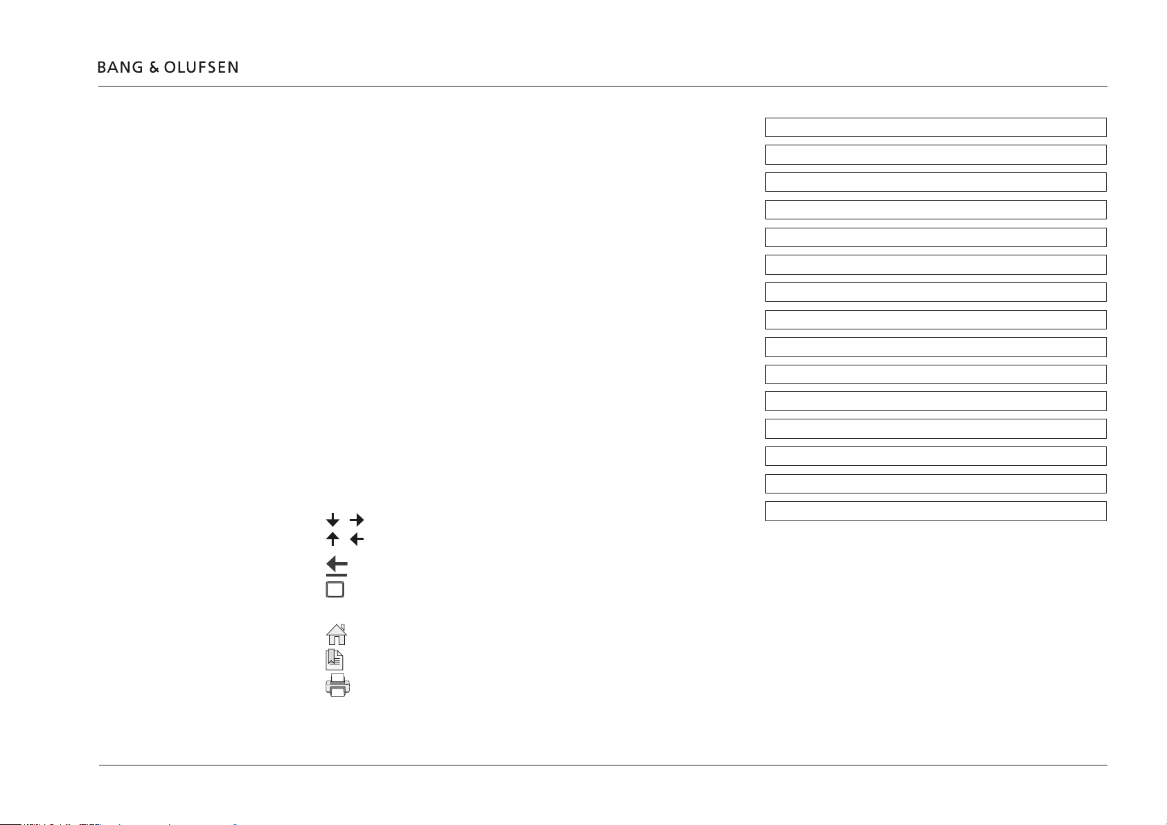
When the guide is opened, it automatically opens in Full Screen Mode (can be left
as desired - see below). This is primarily done to optimise the usability of screen
reading. There are several ways to navigate when using the guide, see the survey
of keys, shortcuts and hot keys below:
/ (arrow keys on the keyboard) navigates to the next page
/ (arrow keys on the keyboard) navigates to the previous page
Introduction
How to use this installation guide
Concept
Terminology
Connection panel
LED indications
Installation overview
Mounting
Home Automation systems supported - connection types
ServiceTool
Cable connections
Accessing the BeoLink Gateway
Setup of BeoLink Gateway
Connection specications
Index
Navigation TIP
Navigates you to the previous view
Esc
(Esc button ) exits Full Screen Mode (press Ctrl + L to return to Full Screen Mode).
Another feature to optimise the navigation is the navigation icons at the bottom of the screen (see below for explanation).
Navigates you directly to the start page
Navigates directly to the table of contents (these are active links - click the link to be directed directly to the associated section)
Prints the document - the print dialogue box opens (Ctrl + P also brings up this feature)
The right side of this page and the Table of Contents, page 3, acts as an active table of contents. Simply click the subject you want and you are
transferred to the section in question.

Concept
One remote
Scenes
One touch operating principle
Setup
Concept 4
One remote control solution can control each product or function in the entire setup. Furthermore more products and functions can be
programmed to scene settings as desired.
Just mentioning a few: light, shades/blinds, temperature regulation, On/Off functions, audio, video, surveillance camera.
Scenes could be: cinema mode, dining mode, good night, coming home, leaving home, start heating/cooling, view door camera, party, etc.
Just by one touch the above scenes are activated. This is despite which operating solution that is chosen. And operation possibilities are of course
adapted to the tool chosen.
The tools are:
- Bang & Olufsen remote control: Beo4, Beo5/Beo6, BeoRemote One.
- Wall panel from the Home Automation system.
- BeoRemote App on iOS based hand held devices.
- TV overlay.
Almost similarly simple is the setting up of the home automation system in the BeoLink Gateway as well as creating macros to be executed when
an event happens.
Almost total freedom exists in designing the home automation control system by creating the areas, zones and placing the systems and resources.
These terms and use are explained in this Installation Guide.
Current conguration
To make a better overview of the home automation installation, the project is organized in: Areas, Zones, Systems and Resources.
An Area is subdivided in Zones. Systems (i.e. the BeoLink system and the various home automation systems) are organized under Systems.
Note: There is full exibility in organizing the structure, although it is recommended to arrange the systems in the ‘global’ area/’global’ zone and to
built and organize a logical structure as desired matching the surroundings that the entire home automation solution shall cover.
These can later be reorganized, renamed, deleted and subdivided further.
The Bang & Olufsen products, possible 3rd party A/V products and all the products making up each home automation system and virtual resources
are all regarded as Resources.
In the Resource page the linking between a product and a zone is assigned.
Every time changes are made - in any of the conguration menus - the changes takes effect immediately - this is the ‘current conguration’.

Terminology
Project
Areas
Terminology - Project - Areas - Zonea 5
Notation:
Often the terms area and zone or area/zone are mentioned at the same time and the notation ‘global‘ area/’global’ zone is often used.
The project dialogue is holding information about where the BeoLink Gateway is used. The display name will be displayed in user interfaces
identifying the installation e.g. by family name, name of house or any other short name.
All other information in this page is only visible when opening the Project page, giving details on identifying the installation, who has made the
installation and contact information. See page 21.
One area may be sufcient to circumscribe the premises that the home automation setup is inuencing. Where the premises are huge, complex or
it is just desired to organize in smaller units, more areas may be created to subdivide the entire premises.
Examples could be an area for each oor level; another example could be to subdivide in living house, courtyard, pool area, and guest house. In
short the number of areas is a matter of subdividing into smaller entities.
Areas can be added, renamed and removed.
Note: each area is subdivided in zones; see below.
global area
A special area is named ‘global’ that is a virtual area. The content can be ‘reached’ from any other area or zone. The ‘global’ area is per default
subdivided in a ‘global’ zone’; see below. The ‘global’ area can be renamed or deleted.
Zones
global zone
Zones are logical entities that are used to subdivide an area. As an example, the living house area may be subdivided into: Kitchen, living room,
sleeping zone, garage etc.
Zones are place holders for resources (see page 30). In the Resources menu the resources (systems) are assigned to the zones.
Zones can be added, renamed and removed. Zones can be assigned an icon (except for the ‘global’ zone), that will be shown in the user interfaces.
A special zone called ‘global’ exists per default under the ‘global’ area. The ‘global’ zone can be renamed if desired. The global zone is the
placeholder for resources (see page 30) that apply to more zones or the entire premises.
The ‘global’ zone is typically a utility room.
The ‘global’ zone can be renamed only and cannot be assigned an icon.
The systems, e.g. BeoLink and home automation systems can be placed in the global zone together with virtual resources; see page 7.

Systems
BeoLink system
Home Automation systems
Virtual Resource systems
Terminology - Systems 6
Three types of systems exists as explained below.
The BeoLink System (i.e. all Bang & Olufsen products based on Network Link and Master Link that are connected to the BeoLink Gateway) is
regarded as an internal system. The BeoLink System can only appear once in the installation. The BeoLink System is per default assigned to the
‘global’ area/ ‘global’ zone’
Each Home Automation system is assigned to an ‘area/zone’. This is despite the Home Automation system, may serve more zones where each of
the products the system consists of are placed.
Systems are invisible in the daily use from a user interface point of view. The Home Automation systems may consequently be assigned to the
‘global’ area/’global’ zone. Systems are usually assigned to zones by the installer in the Systems page.
The products making up the system are linked to the area/zone in which it is physically placed. This is assigned in the Resource page.
A Virtual Resource system is per default assigned to the ‘global’ area/’global’ zone. The Virtual Resource system is the place holder for virtual
resources.

Resources
Virtual Resource
Terminology - Ressources 7
Resources typically fall into a group as e.g.: button, function, device etc.
Resources are identied by:
- Zone: The zone they belong to.
- Name: A name for easy identication. (The name can be 200 characters in length. The ASCII characters from 32 to 126 (incl.) can be used.)
- Type: A type e.g.: button, function, device etc.
- Address: An address that is a unique identier. The format of the identier is system dependant.
When a resource is placed in an area/zone that are later reorganized i.e. deleted, the resource must also be reorganized. The area/zone can rst be
deleted when no resource or system is related - else a message appears.
A Virtual Resource is typically a button (scene) operated from the user interface, and it is programmed by a macro. A ‘Virtual Resource’ is per
default assigned to the Virtual Resource system.
A Virtual Resource has no function itself, but the related macro executes the programmed user actions.
The ‘BeoLink’ system (as concept) is per default assigned to ‘global’ area/’global’ zone.

Macros
Events
Commands
Terminology - Macros 8
Macros are used to organize interaction between the different devices in the home installation.
A macro consists of events and commands. When an event happens the commands will be executed in order. In other words, the Macro is
triggered wether it is physical (e.g. a button) or virtual (on a user interface).
Macros are assigned to zones where the event takes place, even when it is physical or virtual.
Events are represented by a code for each row of the event list (any code start with: ‘area’/’zone’/’type’/’name’ followed by a value or an action.
An event is either of the three types:
- Resource event, matching a specic event on a specic resource.
Example: LIGHT 3 was pressed on the TV in the dining room.
- Generic event, apply to a set of similar events throughout the house. (more zones).
Example: a button named PARTY was pressed on any zone, any area.
- System event, include calendar and astronomical clock events, front panel button events and system connectivity events.
Commands are the actions executed whenever a macro is triggered.
Commands can be either of the four types:
- Generic commands apply to any area or zone, with the option to select the same area or zone where the event was generated.
- Resource commands apply to a specic resource.
- System commands act directly on the systems that support them.
- Macro commands call other macros, or act on other macros.
Interfaces
Users
B&O Products
Cameras
Zones setup
Favourites Lists
User Interfaces
Webpanel
Terminology - Interfaces 9
In the Interface page settings and handling of: users and user rights; conguring A/V products, cameras; zones and favourites lists are made.
The following is just an overview; see details page 40.
The users with administrator rights can create new users and handle user properties and user rights
Settings for each A/V product and related sources can be handled; i.e. which source buttons to display on the BeoLink App..
Setting up cameras is made from this subpage.
For each zone, the resources are listed and some settings can be changed and the resource can be made hidden/visible.
Is a list of provided channels for radio or TV (e.g. subscribed to). Examples are Boxer, ViaSat, Sky, etc.
With each of these source providers, it is possible to set up favourite channels.
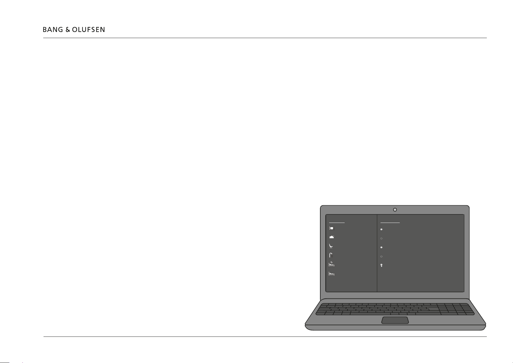
Access BeoLink Gateway using a web-browser on a computer and
enter the IP address (e.g. 192.168.1.10) as URL.
ZONES
FLOOR 1
CINEMA
FLOOR 1
KITCHEN
FLOOR 1
LIVING ROOM
FLOOR 2
BATH ROOM
FLOOR 2
CHILD ROOM
FLOOR 2
SLEEPING ROOM
FLOOR 1
CINEMA
CINEMA ON
CINEMA OFF
LIGHT ON
LIGHT OFF
CINEMA LIGHT
ROOM OFF
xxx
LEAVE
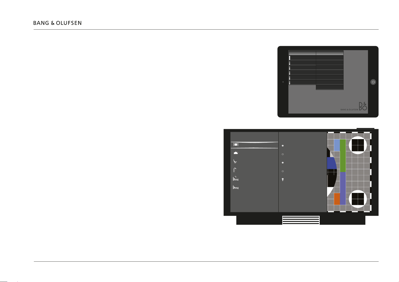
BeoLink App on a hand held device.
Via iOS based devices using the BeoLink App. Note that the device must access the same
home router/AP as the BeoLink Gateway is connected to.
TV overlay
Via Network Link based TVs, using a remote control:
- BeoRemote One: Add HOME CONTROL to the TV LIST. It is
recommended to keep the HOME CONTROL as one of the
top positions in the displayed for easy accessibility.
- Beo4 (Type 1710 or newer and with Database 1.30: check
by your Bang & Olufsen retailer). Add HOME CONTROL to
the TV LIST.
It is recommended to keep the HOME CONTROL as one of
the top positions in the displayed for easy accessibility.
- Beo4 (Type 1710 and newer; with old FirmWare). Add
RETURN to LIST (Stby+LIST, then press <Centre> and select
AV? using <Centre up> and press <Centre>, then select
REMOTE using <Centre up> and press <Centre>, and
ADDED is shown to conrm selection. Press and hold BACK
to leave setup.
It is recommended to keep the HOME CONTROL as one of
the top positions in the displayed for easy accessibility.
ZONES
FLOOR 1
CINEMA
FLOOR 1
KITCHEN
FLOOR 1
LIVING ROOM
FLOOR 2
BATH ROOM
FLOOR 2
CHILD ROOM
FLOOR 2
SLEEPING ROOM
FLOOR1/CINEMA
FLOOR1/KITCHEN
FLOOR1/LIVING ROOM
FLOOR2/BATH ROOM
FLOOR2/CHILD ROOM
FLOOR2/SLEEPING ROOM
FLOOR 1
CINEMA
CINEMA ON
CINEMA OFF
LIGHT ON
LIGHT OFF
CINEMA LIGHT
ROOM OFF
xxx
LEAVE
ZONES
Terminology - Interfaces 10
SCENES
CINEMA ON
CINEMA OFF
LIGHT ON
LIGHT OFF
CINEMA LIGHT
ROOM OFF
LEAVE
Network source
Network source is a source selected from another Network Link product (borrowed source).
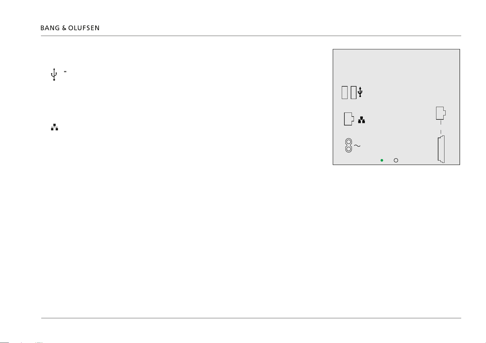
Connection panel
USB (RS232)
5V
USB (RS232)
0.5A
NETWORK LINK
NETWORK LINK
~
MASTER LINK
Connection panel 11
The USB sockets (two pieces) are for RS232 and RS485 connections to Home
Automation systems. A USB to RS232 (D-SUB 9) cable is needed; e.g. Bang & Olufsen
Part No. 6100051. For RS485 connections an RS232 to RS485 converter must be
added to the above mentioned cable.
When more than two system using RS232 protocol are connected a USB hub is
needed.
The NETWORK LINK socket is for RJ45 connectors to connect the BeoLink Gateway
to the Network Link switch or B&O Recommended Router. The BeoLink Gateway will
either receive an IP address via DHCP or have a static IP address; see page 19.
IP-based Home Automation systems are connect to the Network Link in the same way.
Network Link Product Cable and Network Link Installation Cable, Cat 7 quality, are
recommended to avoid non-desired noise and interference.
The mains socket is for the connection to the mains.
The MASTER LINK sockets (RJ45 and ML) are used to connect products connected in a Master Link system. This makes it possible to control a
compatible audio and video system throughout the entire setup. The connections in the RJ45 socket are also found in the ML socket; see
page 58.
5V=
USB (RS232)
0.5A
NETWORK LINK
LED SETUP BUTTON
RJ45
MASTER LINK
ML
SETUP BUTTON
LED
The RJ45 socket is used if the Master Link cable is equipped with an RJ45 plug.
The ML socket is used if the Master Link cable is equipped with a Master Link plug.
The SETUP BUTTON can be used during normal operation by pressing and holding the button; see page 12.
The LED indicator gives feedback about the status of the system and about functions chosen with the SETUP BUTTON; see page 12.

LED indications
Functions - by Setup button
LED indications 12
The LED in the lover edge of the connection panel gives feedback about the system status of the BeoLink Gateway.
Green Red Description
Solid - Normal operation
Flashing quickly Flashing quickly Critical error
- Solid H8/FEP/FPGA update
Flashing slowly - Software update/System boot
- Flashing slowly Master Link synchronization
The Setup button placed next to the LED provides a number of functions as
described in the following.
- Press and hold the Setup button and the system will cycle through the functions. The LED indicates the function number by ashing red a number
of times: function no 1 = one ash, function no 2 = two ashes, etc.
- Count the number of red ashes while holding the Setup button, and when the desired number is reached let go the button.
- The LED indicator starts to ash red.
- To conrm the function execution the setup button should be pressed again within 3 seconds.
No. Function Description
1 System event Executing macros with EVENT
2 Reset password to default ‘Password’ to factory default
3 Fixed IP-address Enables the default static IP-address (192.168.1.10)
4 Factory default Erases conguration and settings
5 - 6 Dynamic IP-address Enable DHCP (dynamic IP-address)
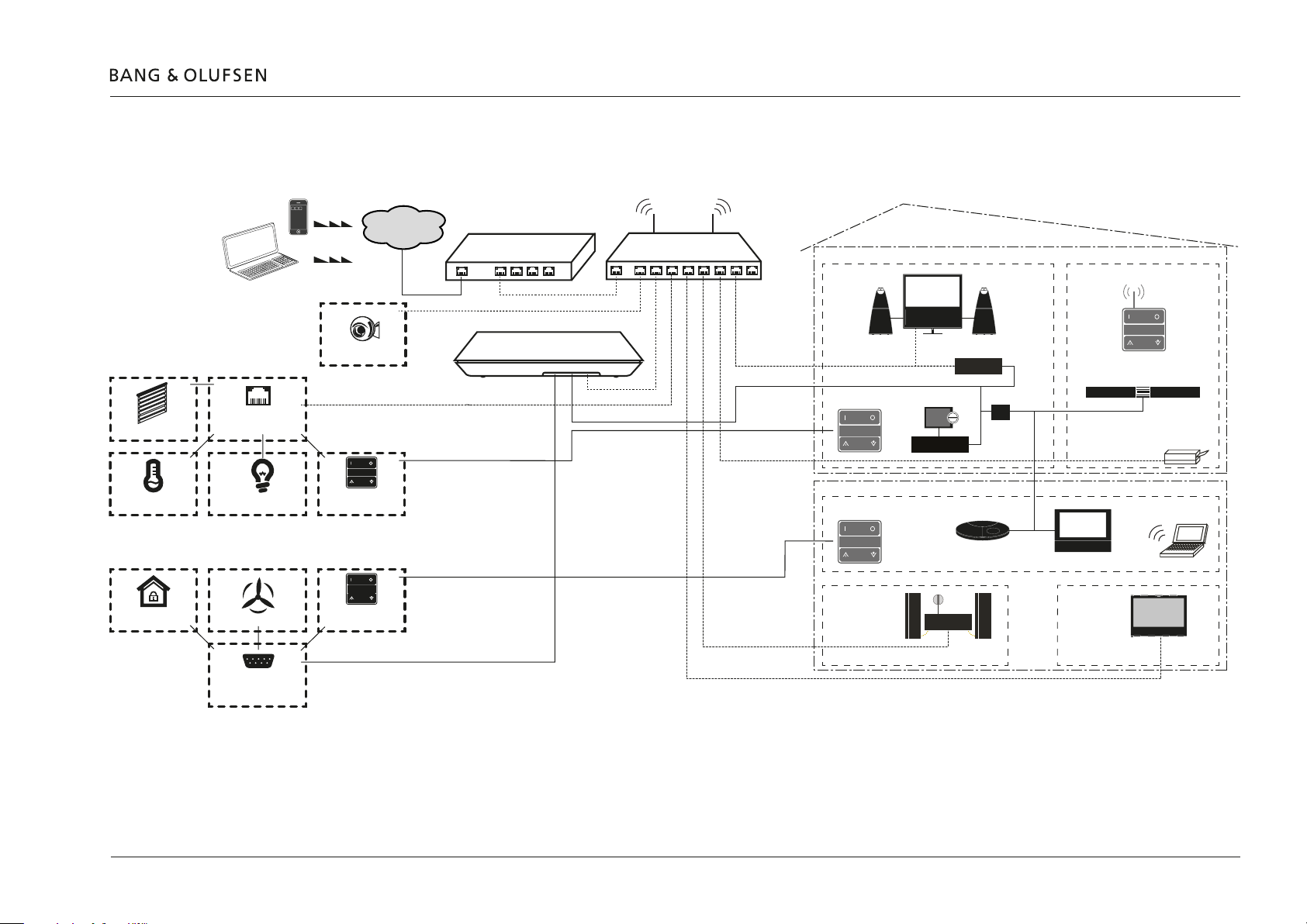
Installation overview
Installation overview 13
Basically there are two different types of connections between BeoLink Gateway and the supported device (home automation systems).
Ethernet or USB/RS232 connection. The connection types are illustrated below:
Window blinds
Heat control
Home Automation System
Alarm system
Home Automation
Contol System
Ethernet
Lighting
Energy control
Home Automation
Contol System
RS232
Web camera
Operations
switches
Operations
switches
Internet
ISP Modem/Router/Switch
Ethernet
RS232-USB
BeoLink Gateway
AP
B&O Recommended Router
Network Link
Master Link
Area 1
Zone 1
*
BeoLink Converter
NL/ML
**
Bang & Olufsen
Area 2
Zone 2
Zone 4 Zone 5
BeoLink Converter
NL/ML
* BeoLink Converter NL/ML
** NL/ML Delay Box
Zone 3
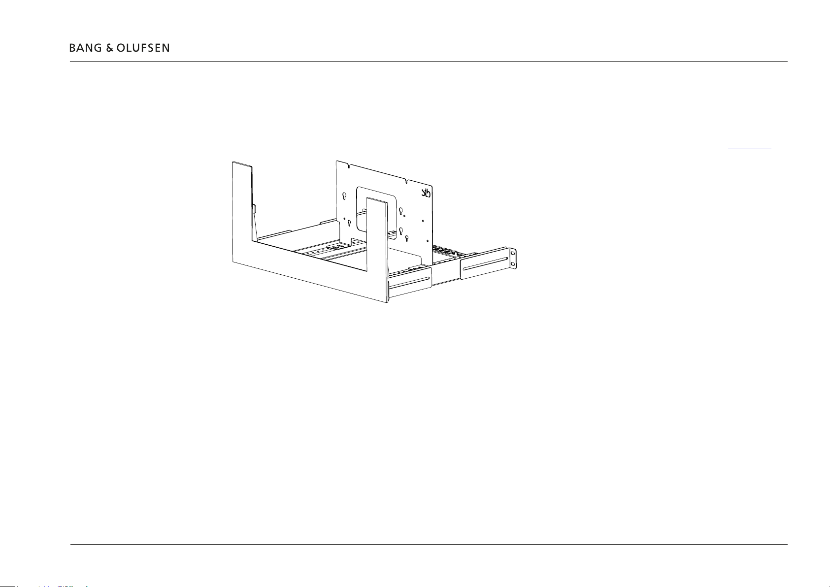
Mounting
Rack mounting
Rack-mount warnings
Operating temperatures.
Mounting 14
A rack-mount installation is preferred if possible. The below illustration is an example of how to place a BeoLink. The BeoLink Gateway may be
placed front most in the subrack which also has room for another 4 similar products (BeoLink Gateway, BeoLink Converter NL/ML) and/or other
Bang & Olufsen products; see BeoWise > 3rd party products > Brackets for possible solutions supported by Bang & Olufsen: see rack mount.
The operating ambient temperature of the rack installation may be higher than room ambient temperature. Therefore, consideration should be given
to installing the equipment in an environment compatible with the maximum ambient temperature of +50°C (+122°F).
Reduced air ow
Installation of the equipment in a rack should be such that the amount of airow required for safe operation of the equipment is not
compromised.
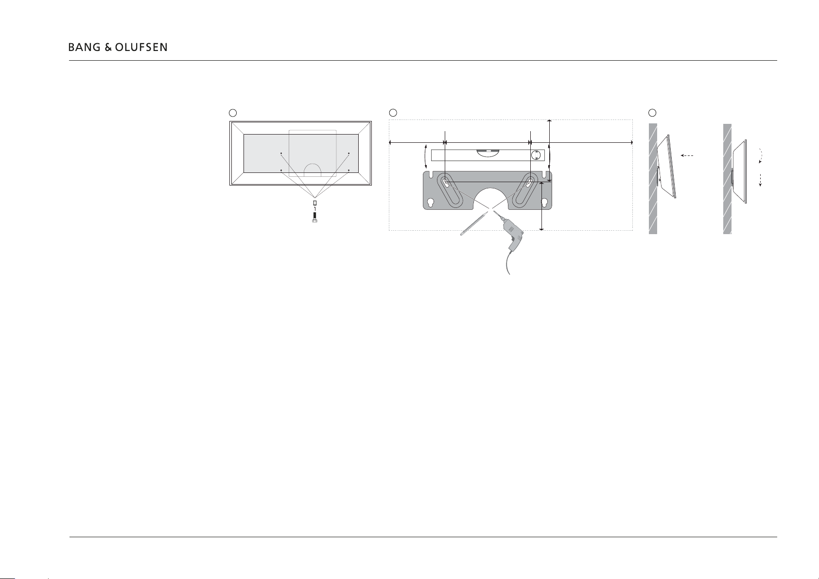
Wall mounting
2.
3.
Shelf placement
Mounting 15
A wall bracket (optional) exists (Bang & Olufsen Part No.: 1200225)
1
2
84 mm (3.32")
130 mm (5.12")
95 mm (3.75")
158 mm (6.24")
75 mm (2.95")
Apply screws in back of BeoLink Gateway.
Mount bracket plate on wall.
Place screws in recess as shown.
When rack-mount installation is not possible, the BeoLink Gateway can be placed on its feet on a stable surface. Such shelf could also be in a 19”
rack. A shelf can take both a BeoLink Gateway and a BeoLink Converter NL/ML placed side-by-side.
3
1.
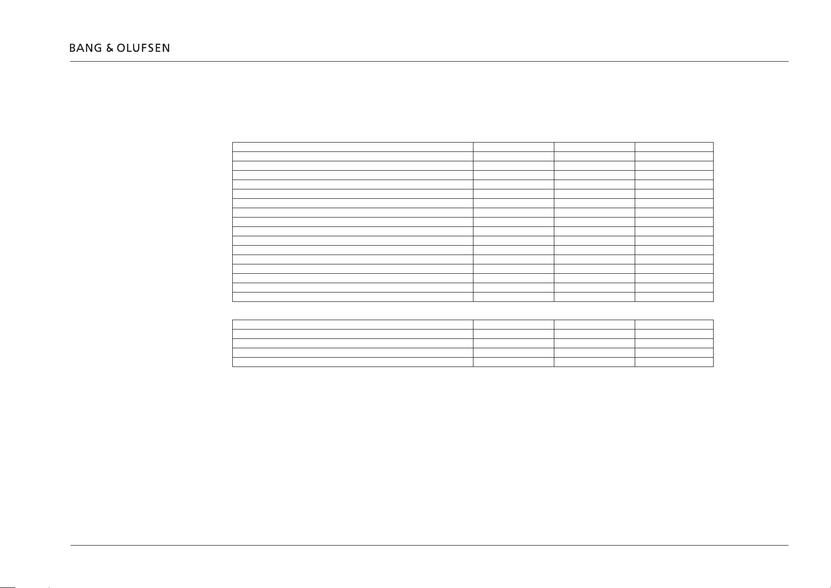
Home Automation systems supported - connection types
The below table gives an instant overview - as per date while writing - of systems supported and their connection type.
See BeoWise > 3rd party products > Home Automation for an up-to-date list of supported systems.
Home Automation system drivers Ethernet connection RS232 connection RS485 connection
Clipsal +
Conson Concept XP (converter from RS485 to RS232 is needed) +
Custom Strings + +
Dynalite +
KNX (EIB KNX, Busch Jaeger) +
KNX (FT 1.2, PEI-IOmode) +
KNXnet (IP tunneling) +
Legrand Bticino +
LK IHC (Intelligent House Control, Viewer models only, LexControl) +
Lutron: Grak Eye (GRX), Grak QS (QSE), Radio RA + +
Lutron: Home Works, Home Works QS, Home Works Radio Ra2, +
Lutron Home Works Interactive +
Phillips Hue +
Smart House + +
Vantage + +
Velux + +
Home Automation Control systems * Ethernet connection RS232 connection RS485 connection
Crestron + +
AMX + +
Control4 + +
Beckhoff + +
Home Automation systems supported 16
! Do not use RS232 cables that exceed 10 metres. Cable length of 2 to 5 metre is recommended.
Use the Help function in the BeoLink Gateway Setup > System regarding details on the BeoLink products and individual home automation
systems.
* Drivers are available on www://mlgw.bang-olufsen.dk/drivers.html and does not support two way status from Network Link Prodducts.

ServiceTool
Software Update
Web interface
Connection
ServiceTool 17
Connect the ServiceTool to the BeoLink Gateway which will support in the following areas:
- SW update.
- Web interface.
This ServiceTool page is used for SW update of the BeoLink Gateway. The available SW packages on the ServiceTool Computer can be searched for
and be installed. Follow instructions on the ServiceTool page.
The Web panel can be viewed on the ServiceTool screen.
The ServiceTool can access the BeoLink Gateway either via the home router/AP or by a direct cable from the Ethernet socket of the computer to
the Network Link (Ethernet) socket of the BeoLink gateway.
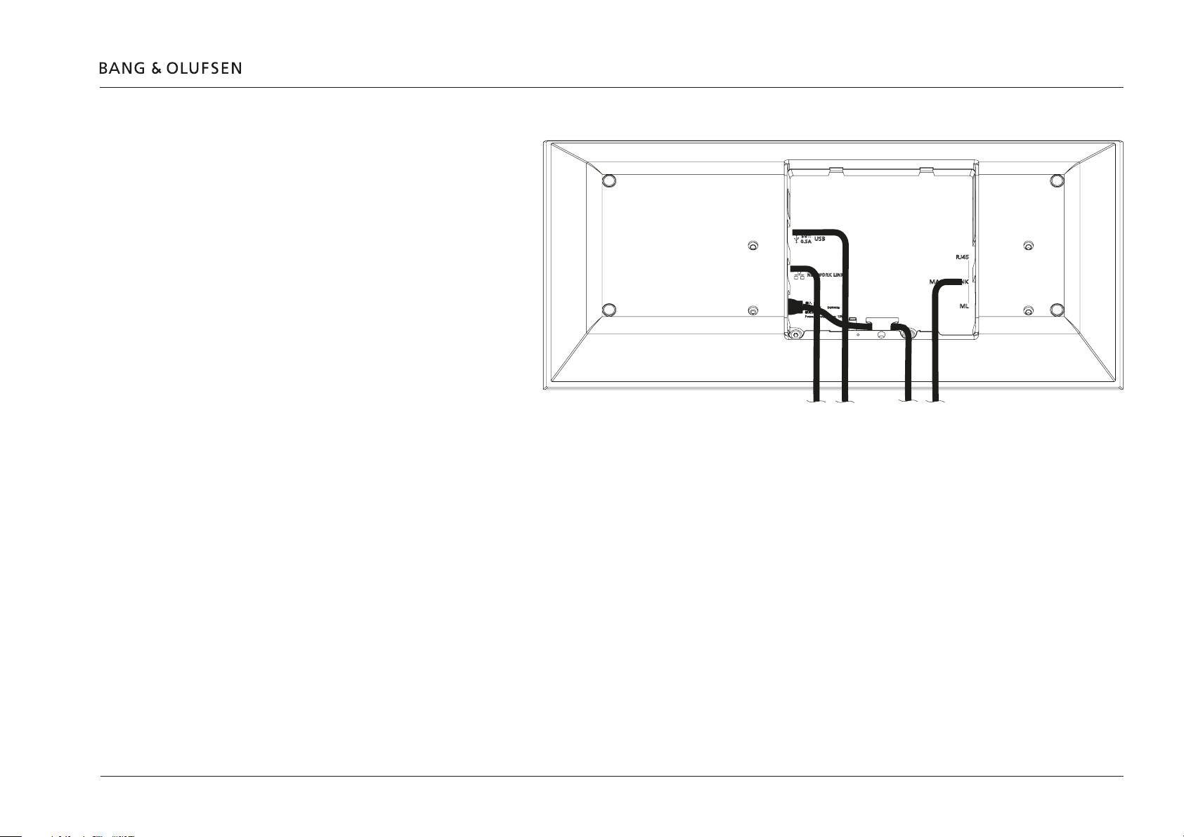
Cable connections
- Connect the Ethernet socket using a
Network Link Product Cable to the
B&O Recommended Router or to the
ISP Router/switch, see page 13.
[See BeoLink Handbook regarding
Active Infrastructure - Network Setup
and regarding appropriate cables].
- Connect the Master Link cable from
the installation to the ML socket.
[See BeoLink Handbook for
appropriate cables].
- Connect the RS232 cable to RS232
based system(s) or to a powered USB
hub that connects to RS232 based
systems.
[The USB to RS232 cable converter
has Bang & Olufsen Part No.:
6100051].
- Mount mains cable in the wire holder as illustrated.
Network
Link
via
Router/
Switch
USB
(RS232)
Mains
Power
Master
Link
Cable connections 18
- Mount BeoLink Gateway in the rack system, wall bracket or place it on a stable surface.
Now BeoLink Gateway is ready for setup.
Accessing the BeoLink Gateway
Accessing in DHCP mode
Accessing in static IP address mode
Accessing directly
Accessing the BeoLink Gateway 19
When BeoLink Gateway is delivered, it is per default set to DHCP. This means it gets its IP address from the router it is connected to.
Access to the BeoLink Gateway can be done in more ways, of which three are dealt with in the following.
The BeoLink Gateway gets its IP address from the router it is connected to (the ISP router or the B&O Recommended Router). Similarly connect the
computer to the router, and enter the IP-address of the router (e.g. 192.168.1.1) in the network browser and look-up the IP-address allocated the
BeoLink Gateway. The computer must be in DHCP mode.
Enter this address in the network browser to access the web-interface of the BeoLink Gateway.
When the BeoLink Gateway is assigned a static IP-address, according to the network plan determined by the router, the web-interface of the
BeoLink Gateway can be accessed by entering this address in the network browser.
To access the BeoLink Gateway in this way, it must rst be connected (in DHCP mode) to the router and the static IP-address is then set as
described in Network settings page 22.
The BeoLink Gateway is set to xed IP-address mode by activating the Setup button function (3); see page 12.
The computer and the Network Link socket of the BeoLink Gateway must be connected directly to each other using an Ethernet cable. The
computer must have an IP address in the same range, e.g. 192.168.1.11 with subnet mask 255.255.255.0.
The BeoLink Gateway is then accessed directly by the factory default IP-address: 192.168.1.10 entered in the network browser.
This method can also be used if the IP address is forgotten.
Discover IP addresses
There are more ways to nd out which IP address a device has in a network. The rfollowing metds are examples:
- Use a network scanner/IP-scanner, e.g. the free-ware: Fing. Best result is obtained using a hand held device; remember to access the Wi-Fi network
used for the BeoLink Gateway.
- Use the BeoLink Setup App; remember to access the Wi-Fi network used for the BeoLink Gateway.
- Use a computer on the same network as the BeoLink Gateway and using e.g. the Safari browser. Lookup BLGW.local as URL and the Bonjour
service will discover IP addresses in that network.
 Loading...