

Page 1
Bang
&
Olufsen
Beo4
Type
1624, 1625
Beolink
Type
1503, 1504
1000,
mk
IV
REMOTE
CONTROL
SERVICE
MANUAL
Page 2

CONTENTS
Beo4,
type'
Beo
link 1000, mk I
624, 1 625 ...........................
V, type
1503, 1504 .
..
............ ............... ......... 1
...
.....................
..
...... 5
Page 3
Bang
8e04
Type
1624.
&
1625
Olufsen
•
SERVICE
MANUAL
Page 4
CONTENTS
Brief
List
of
mechanical
operation
guide
parts
..........................................................
....................................................... 2-1
1-'
•
Disassembly
Adjustments
Service facilities via
Service
Repair
Keyboard does
No
IR
Display does
Fault in
........................................................................... 3-1
and
repair
position
guide
.......
/ display OK ........................
the
tips
keyboard
...............
not
work
not
work
display ...
................................................
English German French
4~
.............
fiR
is
...
OK.
1
4~2
4~2
4~3
4~3
4~3
4~4
4~5
4~6
4~6
4~7
4~7
4~8
4~8
4-10
4~10
4~
4-12
4-12
4~
4-'
4~9
"
12
•
•
Page 5
Bang & Olufsen
BRIEF
1
-1
OPERATION GUIDE
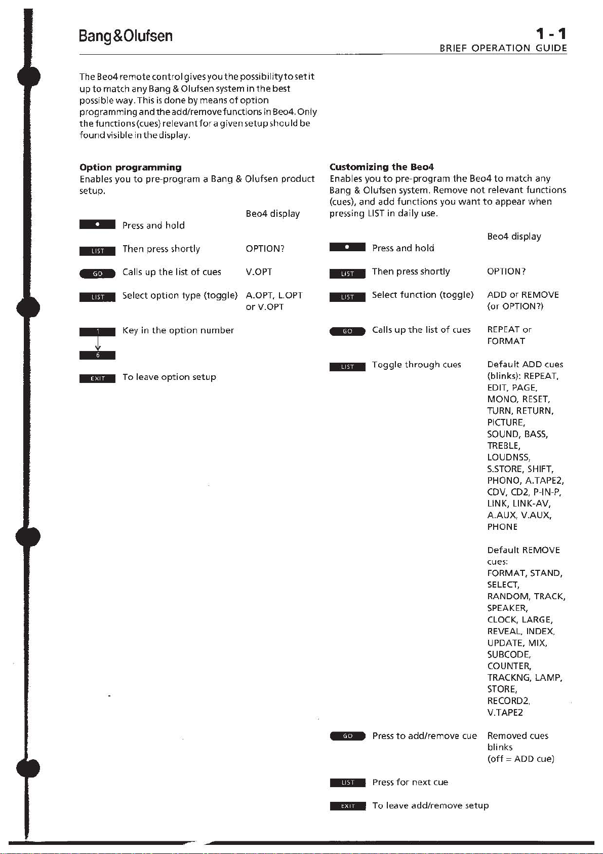
The Beo4
up
possible
programming
the
found
Option
Enables
setup.
.,ri.
Mri.M
.In.
remote
to
match any Bang & Olufsen system
way.
functions (cues) relevant
visible
programming
you
control gives you
This
is
done
and
the
add/removefunctions in Beo4. Only
in
the
display.
to
pre-program
Press
and
hold
Then press shortly OPTION?
Calls up
Select
Key in
the
option
the
option
list
type
:t
To
leave
.131_
option
the
possibilityto
by
means
of
option
for
a given
a Bang & alufsen
of
cues V.OPT
(toggle)
number
setup
set
in
the
best
setup
shou
Id
product
Beo4 display
A.OPT, L.OPT
or
V.OPT
it
be
Customizing
Enables
Bang &
(cues),
pressing
.!bM
.1
..
.1
you
Olufsen
and
LIST
Press
Then
Select
••
Calls
.,;=
Toggle
••
add
the
Beo4
to
pre-program
system. Remove
functions
in
daily
use.
and
hold
press
shortly
function
up
the
list
through
the
you
want
(toggle)
of
cues
cues
Beo4
to
match any
not
relevant
to
appear
Be04
display
OPTION?
ADD
or
REMOVE
(or
OPTION?)
REPEAT
FORMAT
Default
(blinks):
EDIT, PAGE,
MONO,
TURN, RETURN,
PICTURE,
SOUND,
TREBLE,
LOUDNSS,
S.5TORE,
PHONO, A.TAPE2,
CDV, CD2, P-IN-P,
LINK, LlNK-AV,
A.AUX,
PHONE
or
ADD
RESET,
V.AUX,
functions
when
cues
REPEAT,
BASS,
SHIFT,
=!I-
.'
..
.ElI.
Press
to
Press
for
To leave
add/remove
next
cue
add/remove
Default
cues:
FORMAT, STAND,
SELECT,
RANDOM, TRACK,
SPEAKER,
CLOCK, LARGE,
REVEAL,
UPDATE, MIX,
SUBCODE,
COUNTER,
TRACKNG, LAMP,
STORE,
RECORD2,
V.TAPE2
cue Removed cues
blinks
(off = ADD
setup
REMOVE
INDEX,
cue)
Page 6
1-2
BRIEF
Cues
A
[AOD7]"
This we
spec
you to add new functions
displa y
(A.OPTP
Please r efe r to
Inf
(A,fAPEJ~
A.
t
ca
Bang & Olufsen a
(A.TAPEl]
For sw
record
audi o
(A,AUX)
F
equipment Pfess
OPERATION GUIDE
In
display:
(ADD A NEW
ap~ar<
ial
ormation.
TAP
E
he Be04
rr y
out
itching
er
system.
or
~witth
Beo4
appe~rs
when you have
letup
(AUD
IO OPTION)
OPTlONl
(AUDIO TAPE
in
ATAPE
button. Any
on th'" 8eo4
udio
(AUDIO TAPE
on a ,econdary
coorl
eded
Pr~
(AUXILIARY AUDIO
in9
on
10
GO
function.
t he
di~play
will
t
to
your
GO
any
to
•
[SASS]
(BASS
For
so
BeoLink r oom.
requ ired.
LOUDNSS.
Inf
or miJlion
(8AnERY)
This cue Indicates t
b
attefle">
t he
c
ICD)"
CD
appea
Be04
on t h e
Olulsen
(COli
For switching
<e"",ln 8/1
GO todo
(CDVI (COM
or
swi tch
f
connec
sy,tem.
[CLOCK] (CLOC
For
displ~ylng
Oluh
e"
GO
"'gain to remove th e t ime).
TONE)
und
~dju~t
ment
Press
Please
...
ref~r
an d SOUND f o r
" (BATIER
hat
in
the
Beo<! remote
(CO
MPACT
DISC
rs In
the
w ill
player.
display
be
directed
DISC PLAn
CD
button. Any
8eo4
CD
(COMPACT
o n a secondary CO player
ng & Ol u lsen
so.
PACT
DISC
ing
on a compact
ted
to your
GO
Bang &
to
do '0.
Press
K)
t he t ime o n certa in Bang
produ
cts. Pr
e-.s
of
to
y)
it
operati
FUNC
TION)
ADD?
((u
e~)
for
fur
ther
RECOROER
when
operat
be directed t o
~pe
recorder.
RECORDER 2)
audiO
B
~rl9
to
do
So.
SOURC
e xtra a
udio
do so.
ba~~
ton~
or'"
to
adju
S.STORE.
further
is time
to change
PlAYER)
when
you press
on
yo
to
your 8ang
R 2)
aud
io systems.
1I1
0EO
PLAYER
d
i~
Olufs
en
GO
t o d o so. (P
a
c~e5led
enables
to
th e Beo4
)
you
ion you
tap
& Olu
f)
in
st as
TREBLE.
(ontlol
...
c~rr
vi d
eo
v)d~o
pr~~
you,
a
ken
~
.
y
in
Pr~s
)
player
8r
ren
F
the
[FORMATI
For
Olufsen
or'"
(INDEX) (TELET
f or calli
GO todo so.
(PICTURE
optimizing
wide-~r
to
do
so.
ng up
the
the
ee n
EXT
teJele
FORMAT)
pic
tur
v;doo
IND
l
(LAMP]
(LAMP LIGHT CONTROL)
For
'wit
ching
setup
on ~ particular
(B~ng
II<
Key
in t he
GO~.
(~LC2Iight
Olufsen lig
a
ppropri~te
light
and
LO).
and press
[LARGE] (TELETEXT' LA
lARGE is used
f or
enlarg
w at ching . Press
on
cel1 a
in g the teJ
GO
ete.
to
rn Bang
do
(L-A..TP2) (LIN K AU DIO TAPE R[CORDER
Ple~
se
re
fer
to
UNK
f or
[L-COV]
(LINK CDII PLAYER)
refer
to
LINK
Please
(L-C02]
(LINK
Please refer to
(LIGHTI"
(LIGHT CONTROL)
LIGHT appeaf5
t he
Be04 LIGHT br.stton
ou
t o n t he Be04 wi
&
Oluken li
[LINK]
(LINK)
UNK
must
button
$witching on your Bang & Olu l s
the
Beolink
o
ut
together
II<
button
be
is
normally specified,
proouct
in t he ,arne ro o m.
(TV,
for
CD PLAYER
LINK
f
or furt
in
th~
displ ay w hen you pr£'!>S
Any oper"'tlonyou
ll
be
di
g ht (ontol(s)
u
sed
where
w hen the
RA DIO, CD. ATAPE
w.
If
you
have
acc~
BI'l04 dIsplay. special cu
o
tthe.., source s WI
display:
[L-A.TP2] (LINK AUDIO TA
For
,electing
[L
-COV) (LINK
For ,electing
(L-C02]
For select
t o any e ... ra KlUrte-s via the
es
ll
t hen a ppear i n
LlNKth~n
(DV
PLAYER)
LI
NK
then
(LINK CD PlAYER
in
g
LINK
t hen
e
form~t
on a Bang &
syste
m.
~r es
,
GO,
EX
PAGE)
.l
Inde
~
page.
Pr~
la mp in
your
ht control,
num~r
(o
nlr
o l on ly.)
RGE)
8;
Olufsen T
t page you are
so
.
further
informa
tion
further
information.
2)
her I
nformation.
rected t o your Bllng
the use
of
II
LlNK-
for
example for
en
~yste
are
S $
a $Our{e
.IIT
placed
APE)
m
to
se
two
~re
f or LlNK-opera
the
8e04
PE RECO
A.
CD
C02
TAPE2.
RDER
V
2)
Let
(1-9).
21
GI'
vi
a a
tio
ILOPTI
' (
Plea~
e
r ef er 10 O
....
informati
(LOUONSSI
For
on.
switching
a BeoLink room. Pr
so
Please ref
SOUND
f or
(L-PHOHOI (LINK PHONO)
r~fer
Please
{L-V.TPZl
Plea~
refer t o LINK
M
(MIX] (TEL
MIX
i, used on cert ain Bang
superimposing the
pIcture.
Prei~
lls
[MONO)
For sw
(MO
itchi ng
(monolster e
on a rad
io·, TII- or
,w
lt c
hing
deo
betWffn
upe
.
vi
o
[OPTION?]" (
Thi s cue app ears
8e04
se
t up functio n. OPTION? enabl
pr
eprogram
s-etup.
Pre-.s
ty
pe
ry
do
n
2)
of option p r epro
make
:
IV.OPT]"
(A.OPT],
(L.OPT]" (LINK
When the r
the
appropri
p
(PAGE) ffEL
se
lecti
For
&
no rma
number
[PHONE)
For 8an g
[PHONOI
F
pl
ng
Oluhen TVs
lly
requiled
you wa n
& Olu f$en professionals
(ReCORD
or
s
witchi
ayer. Pr
e"
Bang&Olufsen
liNK opnON)
PTI
ON? f or
furt
(LOUDNES
th!;> loudness
er to
fu
rt~r Inform~tion.
to
(LI
NK IItO
ETEXT:
GO
NOI$TEREO SOUND)
bet
oll
Prr
m
OPT
your Ba
GO. t h en pr
(1I10eo
(AUDIO o pnON)
ight
ate
EnXT PA
t~l
ng on a Bang
GO
S)
function
ess GO
repeatedly
S.S
TORE.
TREB
l
INK
f or furt
her
EO
TAPE RECORDE
for further inf
MIX)
...
lelete~t
to
do
ween th
angu<lge) cUffe
ule
t he w u
GO
r
Oluf,en TVs
page
10.
e t yp es of
ntl
.. ite p. o
nd track.
epeat~dl
ION PREPROGRAMMING)
w h en
you
access
ng & OJulsen
£'!>S
LIST
grammi
ng you w ant t o
OP
TION)
OPTION)
optio
n
cu
e is
n n
di.played
umber.
optio
GE SH£CT10N)
eted
pag'"
(where
f or
t;
on certain
pressing GOTO
,"
(ces
s).
or press
....
Ke
or
PlAYER)
.... Olut,
to
do
10
,
her
on/off
to
LE,
BASS,
informatio
o rmatio
00
the
~ound
y available
gram
; o r
on
v
to
do
the
special
e-.
product
to disp
I
y in
the
....
only.
en r ecord
do
and
n.
R
2)
n .
TV
for
a
'0
.
yo u
to
lay the
. key in
Bang
~
page
in
for
(COUNTER) (COUNTER POSITION)
Allows
you to
key
positi on you wa
do
KI
.
jun
button
s.
pre"
nt
[ he
m a specific cou
to
fin
d o n a vi
app1"
Dp{'i
ate
E
(EDIT]
For
futur
e use.
nter
deo
num
t ape To
ber
IL-PHONO) (LINK PHONO)
For selectin g
UNK.
t
hen
(L-V.TP21 (LINK IIIDEO TAPE
For
s~lecting
(LiNK-AV]
To
obtain
II<
Olufsen video sy.te
w
ith video
P
r""
. f o r examp le, T
LINK
then
(LINK AUDIONIDEO)
stereo sound
from
m in e Beo
products (TV
r'vldoo
il
or VTAPE
PHONO .
RECORDER
V.
TA
PE2.
yo
...
Unk
t~
p e
to
2)
r central Bang
room
reco rder).
do so.
While PHONO
ng
. you may p .
playi
through
the musIC;
and
GO
10
pause
(PICTUREI
For ope r
the PIGUR
Ol
...
mo
ating
fsen
r~mot
tor
ized n and,
(PICTUFlE)
E b
IS dlsplay.d,
e'll
....
and you may pres.
lin
d resume
t he
v~rlo
ui
...
tton
o n
e
othe
co
ntr
o l
(pictur
pktur
e-in. picture. etc.).
and
the
or ...
reco
to
step
playback.
functioo,
related
r recent BMg &
e adjustme
rd
STOP
nt,
is
to
Page 7
Bang&Olufsen
[P-IN-P]
(PICTURE-iN-PICTURE)
For
operating
on
certain Bang & Olufsen
example)
sm~11
Note:
four
coloured
picture
the
picture
While
around
the
picture-In-picture
TV
button
P-IN-P
is
displayed,
buttons
on
the
TVs.
to
moves
'c'een
Press
call
up
TV in
pr~ssing
the
small
function
(for
the
R
[RADI01~
RADIOappearsinthe
the
~a
&Olufsenradio
[RANDOMJ(RANDOM
Fo"witch
recent
do
IRECORD2] (RECORD ATAPE2NTAPE2)
Starts a recording
Olufsenaudio
twice
(REMOVE?]*
This
special Be04 setup
en~bles
th~
[REPEAT]
For
function
Pre,s
[RESET] (RESEn
Forresetting pictlJre orsound adju';!:ment,totheir
preset levels.
(RETURN] (RECORD RETURN)
for
Bang
spotwherea
(REVEAL] (TELETEXT: REVEAL)
For revea
Bang &
(RADIO)
Be04 RADIO
rry
outonthe
ing
Bang &
SQ.
to
start
cue appears
you
Be04 display.
(REPEATED
'witching
in
recent
GO
to
operating
&Olufsentape
ling concealed
Olufsen
display
when
button,
Any
Be04 will be
you
operation
directedtoyour
PLAY)
on
the
random
play; n9
Olufsen
CD
On a secondary
orvid",o
recording.
to
do
the
recording
tape
(REMOVE A FUNCTION)
when
you have accessed
function.
remove
functions
PLAY)
on
the
repeated
Bang & Olufsen
so.
Pr~ss
GO
to
record return function in certain
r~orders.
started, press
teletext
TVs.
Press
play"",_
recorder.
REMOVE?
playing
do
so.
To
information
GO
to
fu
Pre"
Bang
(cues)
CD
returntothe
do
press
you
netian
GO
&
Press
from
players
GO.
so.
5
(SAT]*
(SATELLITE
SA T appears in
the
Be04
out
Olufsen
(SELECT]
Forfutureuse.
(SHIFT] (SHIFT)
Foroperatingcertainfunctionsrelatedtothe
SHIFT
remote
ForBdng
[SOUND]
Foroperatingthevariousfunctionsrel~tedtothe
SOUND
remote controls (sound adjustment).
SAT
on
the
,atellite
button
control~.
& Olufsen
button
TV)
the
display
button.
Be04
will
operate
TV.
on
other
Press
profession~ls
(SOUND)
on
other
when
you
your
or 9 to
press
you carry
Bang &
do
only!
Any
oper~tion
recentBang & Oluf,en
0,
3,
6, 7
recent Bang & Olufsen
(SPEAKER]
For selecting
wa
setup.
displayed, pressing .... '1'.
loudspeaker balance.
the
(S.STORE] (SOUND
For
permanent
current
referto
furtherillformation.
(STANO] (STAND)
For
83flg
sy~em~
»to
[STORE]
in
For
to
storing Bang &
press GO, key
press
(SUBCODE] (TELETEXT SUBCODE)
GO
foroperati
Bang &
T
the
(TEXT]'
TEXT
Be04
on
the
any)
watching.
(TRACK]
Forfuture
(TRACKNG] (TRACKING)
Forinstanttrackingadjustmentofthevideotape
you are
(TREBLE]
For sound adjustment
room.
Please refertoS.STORE,
SOUNDforfurther
in
[TURN]
For
audio
Press
[TV]>
TVappears in
8e04TV
the
OlufsenTV.
(LOUDSPEAKERS)
the
nt·
in a Bang & Olufsen surround sound
Press
~toring
sound levels simultaneously. Please
TREBLE,
turning
on
do
,toring
GO
Olufsen
a ppears in
TEXT
Be04 wi
on
the
watching.
Press
(TURN)
"turning"
tape
GO
(TV)
button.
Be04will
number
1-5
to
your
adjusted
setting. Pressing
BASS,
certain Bang & Olufsen
their
motorized
so;
or
key in a preset stand
(STORE)
teletext memory
Olufsen
in
the
again.
ng
theteletextsubpagefunction
TVs.
(TELETEXT)
the
button.
II
oper~te
TV
program
use.
(TREBLE
....
or'"
information.
thetape
recorders
to
do
so.
the
display
Any
bedirected
u
(UPDATE] (TELETEXT UPDATE)
Foroperating t
Bang
so.
Repeattheoperationto
has been
Olufsen
heteletext
& Olufsen TV,.
updated;
TVs.
pres~
v
(V.AUX]
For
connected
system.
(AUXILIARY VIDEO
,witching
to
Press
on
your
GO
to
Bang & 0 I ufsen
to
of
loud'peakers
do
so. WhileSPEAICER
«.
or»
adjusts
STORE)
lound
levels
GO
storesallthe
LOUDNSSandSOUNDfor
video
stands.
Press
position
page<>.
light
appropriate
d ispl
ay
Any
oper~tion
the
you are
Press
....
TONE)
oftreble
to
adjust
BASS,
i n certain
to
play
when
operation
toyour
update function in
Press
se ~
or,
for
certain Bang &
».
a ny
extra
do so.
(and
setups). To do so,
number,
when
you
pre"
you carry
teletext
function
currently
or'"
to
adjust.
tone
ina
as
required.
LOUDNSS.
Ba
ng & Olufsen
the
other
side.
you
press
you carry
Bang &
GO
to
do
p~g~
SOURCE)
video equ i
video
so.
when
th~
you
is
as
a
"''''
for
and
in
t he
out
BeoLink
and
the
out
it
pment
BRIEF
[V.OPT]*
Please
information.
(V.TAPE]*
V.
Be04
outonth~
Olufsenvideo
(V.TAPE2]
For
recordercon nected
video
or
(VIDEO OPTION)
refer
T APEapP"ars i n
VT
APE
Be04will
switching
system.
Maintenance
Cleaning
The Beo4
a soft,
water
Changing
When
display,
change
There are
(if
under
that
batteries
When
must
display reads TV. The Be04
then
Note:
on
replaced
on
*
The cues avai/able
subject
Cues
are
remote
and
the
remote
lint-free
and
wrung
the
the
cue
it
is
the
three
the
lid on
you use 1.5
only.
you have replaced
wait
for
ready
to
We
recommend
top
of
the
Please
note
to
change
in
the
produced
control. These cues are
cannot
OPERATION GUIDE
to
OPTlON7for
(VIDEO
the
button.
be
tape
recorder
(VIDEOTAPE
on a secondary
to
Pres<
Be04
control
cloth which you have
out
batteries
BA
TTERY appears in
to
inform
batteries
batterie,
the
volt
~bout
oper~te
batterie~
...
in
without
Lexicon
automatically
be
added/removed.
further
TAPE
RECORDER)
display
when
Any
operation
dir~ct~d
toyour
RECORDER
video
your
Bang & Olufsen
GO
to
do so.
may be
firmly.
you
that
in
the
remote
in
the
back).
We
(size
AAA)
the
batterie"
10
seconds
remote
again.
that
you k",ep a
until
the
the
8e04
prior
marked
\ are
by
it
Be04
Alkaline
until
display are
the
permanent
1-3
you
pres<
you carry
Bang
&
2)
tape
wip~d
with
dipped
the
Be04
i,
time
to
control
(placed
recommend
you
the
control
fin9",r
lid
is
notice!
CUes
that
8e04
the
in
is
all
Page 8
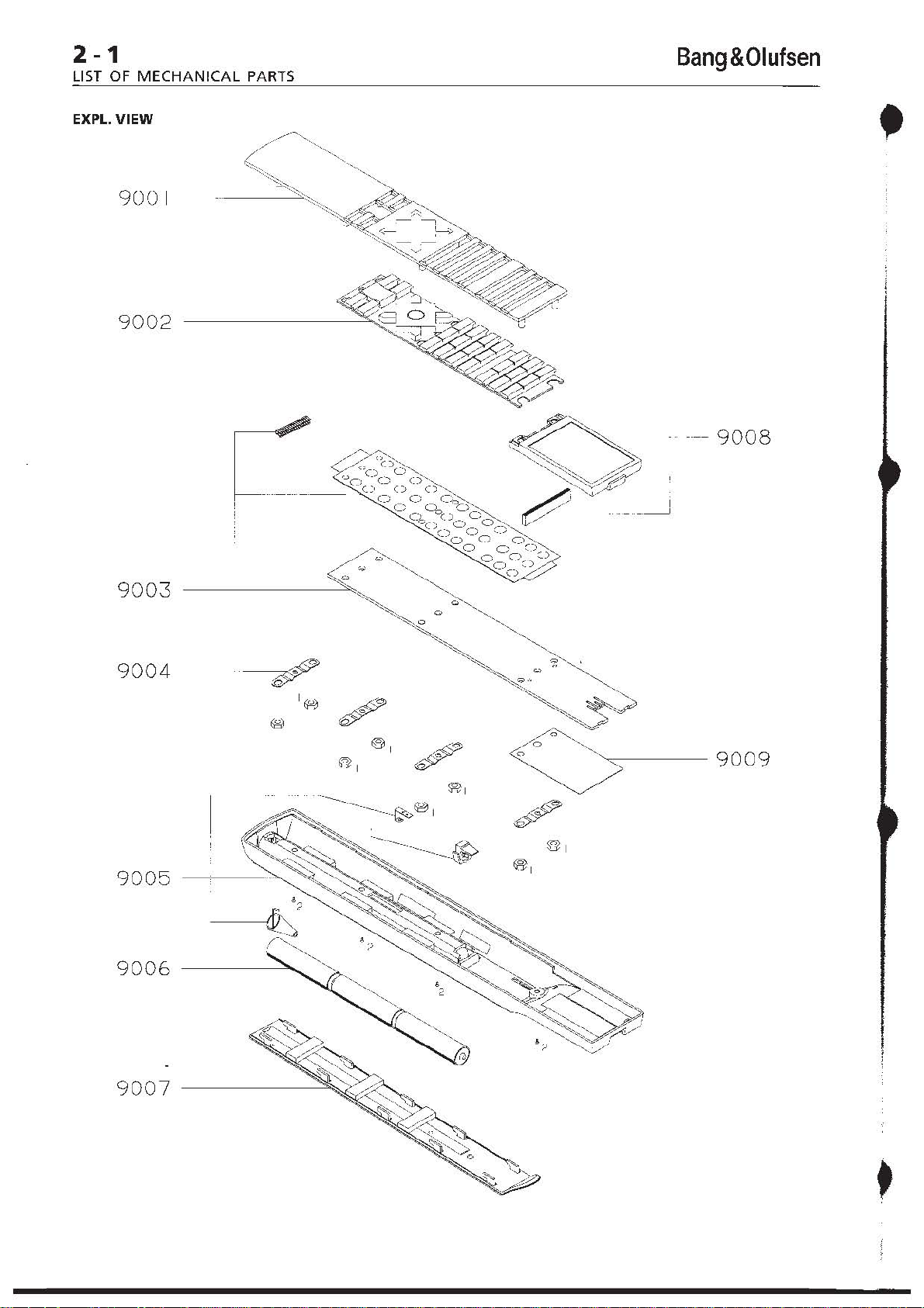
2-1
LIST
OF MECHANICAL
EXPL.
VIEW
9001
9002
Bang&Olufsen
PARTS
9003
9004
9005
9006
--~'
-------"
9009
9007
Page 9
Bang&Olufsen
LIST
OF
MECHANICAL
2-2
PARTS
LIST OF
Survey
Parts
not
Owners
MECHANICAL
of
screws
ets.
shown
manual
PARTS
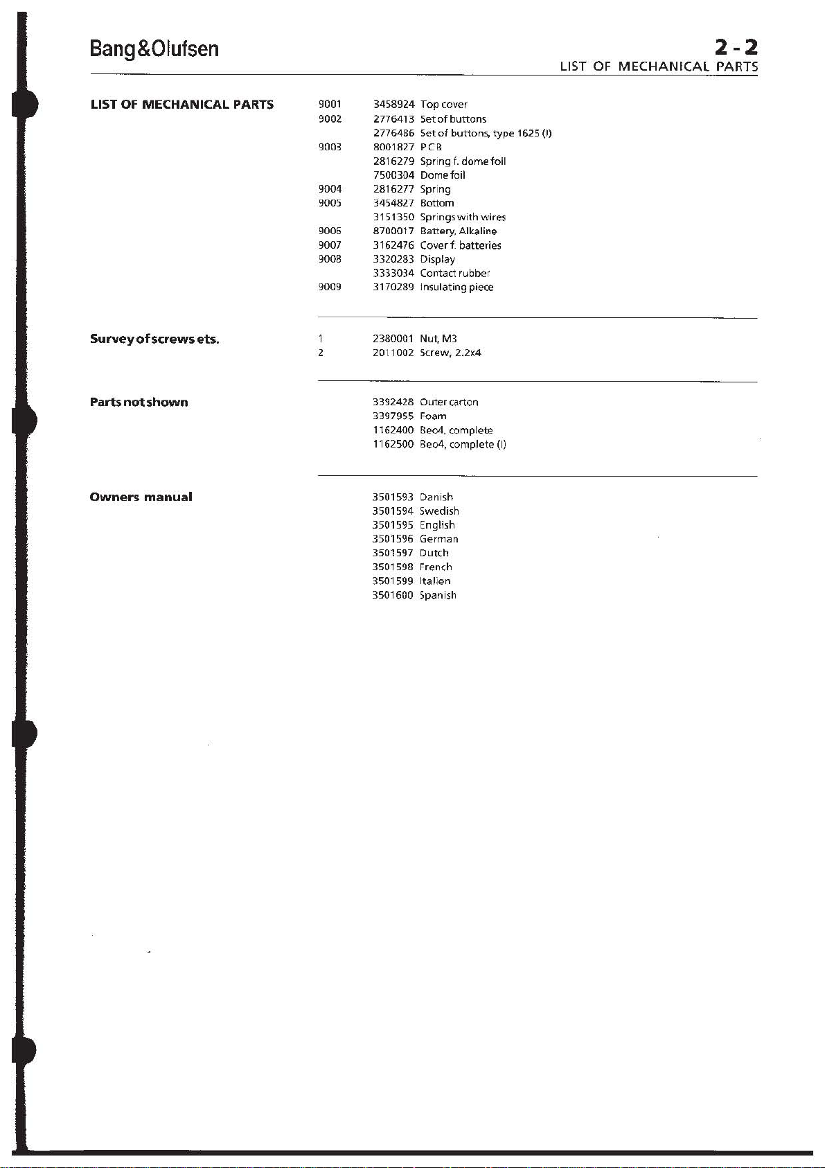
9001
9002
9003
9004
9{)()5
9006
9{)()7
9{)()8
9{)()9
2
3458924 Top cover
2776413
2776486
8001827 PCB
2816279 Spring
7500304
2816277 Spring
3454827
3151350
8700017
5et
of
buttons
Set
of
buttons,
f.
dome
Domefoil
Bottom
Springs
with
wires
Battery, Alkaline
foil
3162476 Coverf. batteries
3320283 Display
3333034
3170289 Insulating piece
2380001 Nut,
2011002
3392428
Contact rubber
M3
Screw,2.2x4
Outer
carton
3397955 Foam
1162400 8e04.
1162500 8e04,
3501593
3501594
3501595
3501596
3501597
3501598 French
complete
complete
Danish
Swedish
English
German
Dutch
3501599 Ita lien
3501600 Spanish
type
(I)
1625
(I)
Page 10

3-1
DISMANTLING
Bang&Olufsen
DISMANTLING
Removal
Push
and
Removethe
Place Beo4
facing
rearendofthe
of
the
battery
remove
down,
top
the
four
with
and carefully I
forwards and off; pay
the
pOSition
window
Placethe
top
plate
of
at
the
bottom
with
plate.
cover
batteries.
screws A.
the
keyboard
bottom
attention
the
leads and
same
time.
to
the
the
module.
fig.
1
forwards,
iftthe
up,
the
right
ofthe
to
IR
ZERLEGUNG
Demontage
Abb.l
Den
Batteriefachdeckel
vorne
schieben
entnehmen.
Die
vier
Schrauben A
Beo4
mit
der
unten
anbringen
hinteren
des
anheben,
abnehmen;
der
Leitungen
Fenster achten.
Den Boden
der
Oberplatte
anbringen.
der
Oberplatte,
nach
und
die
Batterien
entfernen.
Tastatur
Endes
nach
und
den Boden
vorsichtig
nach vorne ziehen
dabei
auf
die Lage
sowie das
auf
der
mit
IR-
rechten Seite
Modul
und
DESASSEMBLAGE
DepoSe
du
couvercle,
Repousser vers
couvercle
puis en lever les piles.
Enlever les
Poser
Ie
Beo4, clavier
Ie
bas.
Souleverdelicatement
I'extremite
avant
et
memetemps
un
des cables
fenetre
Poser
avec
IR.
Ie
fond a droite
Ie
module.
I'avant
du
compartiment
quatre
du
fond,
I'enlever. Repererdans
I'emplacement
et
faire
fig.
Ie
vis A.
orient~
latireren
attention
du
couvercle
1
a piles,
vers
a la
•
hemenex
Fig. 1
Fig. 2
Page 11

Bang&Olufsen
3-2
DISMANTLING
Removal
Removal
to
replacement
rubber
of
of
keyboard, keyboard
display, and,
itself.
Remove
hold
the
four
spring-bronze screw holders
C,
and
the
the
IR
diodes.
If
the
module has
it
is a good
leads
from
before
ca
up
and
out
display. Carry
adjustment
module
The
place by
i mporta
domefoil
the
clamp
installation.
(NOTE!
points
The
but
F
Carry
when
display.
(NOTE!
poi nts
yourfingers!)
The
removed
careful
tearing
press
holes
Note!
When
electrical contact
all
nuts are tight
e\peci~
place
orthe
keyboard
the
ntthatthe
contact
when
Nevertouchthecontact
with
display
look
out
lying
loosely
out
replacing
Nevertouchthe
or
the
rubber
if
you
the
the
inthetop
~5sembling
Ilythe
two
module
the
ofthe
of
course,
the
six nuts B
module
insulation
idea
the
refu
Ily I itti
of
the
when
module
top
in place,
to
to
battery
ng
I R
window
out
contrast
replacing
PCB,
gives
plate,
the
piece D
be replaced
unsolder
supply
the
display_
domefoil
metal
clamp
keyboard
is
placed accurately
points
by
the
carrying
yourfingers!l
can
for
contrast
contact ru
keyboard
but
you
want
soft
rubber
Be04 it
su
rface, a re
but
not overtightened-
nuts holding
out
now
be
the
contact
inthe
display.
adjustment
the
module
bber
can
have
to
to
try
rubber. Carefully
keys
out
plate.
is
important
dea
the
fig. 2
access
domefoil,
module
which
the
the
modu
by
the
is
held
E.
It
on
metal
the
lifted
off,
rubber
or
the
contact
with
now
be
very
to
avoid
of
the
that
n. a nd
that
display
Demontage
Abb.2
Nach
Demontage
sich
Oberplatte,
'Domefoil'
sowie
m6glicherweise
selbst austauschen.
Die sechs
Modul
festhalten,
at
Ie
the
in
is
be
all
in
Schraubenhalter
Federbronze C sowie
Isolierstuck D
Dioden
MuS
entfernen.
das
ausgetauscht
vorteilhaft,
der
Batterieversorgung
abzul6ten,
dem
IR-Fenster
vorsichtig
herausgehoben
Kontrasteinstellung
Austausch des
Displays
Die
'Domefoil'
mit
Hilfe
festgehalten.
die
'Domefoil'
der
Montage
auf
den
fixiert
wird.
(Achtung:
KontaktWichen
berOhren I).
Das
Display
abgenommen
hierbei
zu
liegt.
Moduls
auf
achten,
Nach
oder
Kontrasteinstell
durchfUhren.
(Achtung:
Kontaktflachen
Kontaktgummi
beruhren!).
Es
ist
jetzt
Gummitastatur
Hierbei
muB
vorgegangen
weiche
wird.
Gummi
Jetzt
vorsichtig
O.,erplatte
herausdrOcken.
Hinweis!
Beim
Zusammenbau von Be04 ist es wichtig.
daB
man
elektrischen Kontaktfli\chen ganz
sind. und daB aile Muttern
straff·
fOr
festhalten.
sich vergewissert, daB aile
angezogen
die
beiden
des
Moduls
des
(PCB),
Moduls
Gummitastatur,
der
Tastatur, Display
das
Modul
Muttern
B,
die
die
drei
das
aus
das
im
Modul
werden,
die
bevor
an-
Bereich
selbst
Leitungen
das
beim
und
wird.
der
so
ist
Modul
Display
Eine
nach
Moduls
oder
durchfUhren.
der
Tastatur
einer
Metallklemme
Es
ist
wichtig,
der
Tastatur
der
Metallklemme
Kontaktpunkten
genau
Niemals
mit
den
Fingern
kann
jetzt
werden;
das
Kontaktgummi
das lose
dem
des Displays
es
im
Display
Austausch des
eine
ung
Niemals
und
mit
den
Fingern
m6glich,
aber
die
aus
die
zu
entfernen.
sehr
vorsichtig
werden,
nicht
damit
zerstDrt
Gummitasten
den
Lachern
vorsichtig
sauber
gut -aber
'ind;
die,
gilt
Muttern, die das Display
be,onder,
lassen
IR-
es
von
aus
des
wird
daB
bei
ist
das
der
nicht zu
Depose
fig.
La
remplacer
caoutchouc,
I'afficheuret,
proprementdit.
E
F
Attention !
Lors
I'
ensemble
II
est
serres mais pas
maintenant
de
la
carte
du
module,
2
depose
Enlever les six ecrous B
maintenant
elastique
perforations
niveau
S'il est indispensable de
Ie
opportun
reliesa
avant
precaution
fenetre
Proceder au reg lage
en
module
La
place
Lors
correctement
clavier sur les
proximite
(Attention!
surfaces
doigts I).
II
de deposer
attention a I'elementen
caoutchouc F qui
contact
solidaire de
au
remplacementdu
I'afficheur.
(Attention!
avec
contact
i).
II
clavier en caoutchouc. U ne
extreme
ne
souple.
lestouches
les
dans
du
important
du
Ie
des diodes
module,
module
couvercle,
Ie
film
bien
Ie
C en
il
peuts'averer
permet
Ie
clavier en
cloqu~du
sur,
Ie
module
module,
la plaque
bronze a trois
et
les isolants D au
IR.
de dessouder les cables
I'alimentation
de
Ie
IR
au
cas
de
rem
soulever
et
de
niveau
placement
Ie
des piles
avec
sortir
de I'
du
contraste
ou de I'afficheur.
pince
meta
Ilique E maintient
Ie
film
du
montage,
cloque
de
du
veiller a placer
Ie
film
cloque du
points
de
la
pince
metallique.
clavier.
contact
Nejamaistoucher
de
contact
est alors possible
I'afficheur.
avec
de
soulever
Faire
assure Ie
mais
qui
n'est
pas
I'
reglage
afficheur.
du
contraste
Pra<eder
moduleou
Nejamaistoucher
ses
doigts
les surfaces de
et
I'element
est alors possible
precaution
pas
dechirer
Appuyer
en
sortir
par
les
Ie
couvercle.
rassemblage du Be04, veiller ~ ce
de,
surfaces
que
trop
l'afficheur).
en caoutchouc
d'enlever
s'impose
Ie
caoutchouc
del
icatement
caoutchouc
trous
pratiques
de
contact sait pro
lesecroussoient bien
(surtout
les
deux
remplacer
par
afficheur.
du
en
de
clavier,
la
les
ses
cas
de
Ie
pour
sur
pour
que
pre
ecrous
en
a
et
de
Page 12

4 - 1
REPAIR
TIPS,
Bang&Olufsen
ENGLISH
REPAIR
Service
facilities
via
keyboard
The repair
When
the
display must be carried out.
of
electronic faults in Beo4
replacing
the
display
or
module,
is
an
The following service information can be
Software version.
EEPROM
Total
Number
Number
Number
Contrast
Key pressed
• + LIST
MENU + GO SW:x.x Press
LIST
LIST
LIST
LIST
LIST
LIST
0
3
GO
LIST
•
version.
number
of
times'"
of
times
of
times
adjustment
of
times
keys have been pressed.
has
been
pressed.
1\
has been pressed.
LIST
has
been
pressed.
in
the
display.
Display
OPTION?
EE:x.x
A:xxxxH
B:xxxxH
C:xxxxH
D:xxxxH
CONT:xx
CONT:03
SW:x.x Repeats
Explanation
When
imultaneously,
brought
EEPROM
Total
been
Number
x
Number
x
Number
pressed x
Current
Two
have
values).
New
Abandons
100 (HEX).
100 (HEX).
based on module replacement.
adjustment
of
the
contrast
obtained:
the
keys are pressed
the
terminal
into
Setup mode.
the
keys simultaneously.
version
number
pressed x 100 (HEX).
digits
to
changed
of
of
times
of
times
of
times
100 (HEX).
contrast
in
the
be
entered
contrast
the
sequence.
service
times
... has been pressed
A has been pressed
LIST
adjustment.
range
(start
facilities
is
keys have
has been
from
00
with
low
adjustment.
.
to
in
15
Correct
,.
..
. I .•
1.:1,.,1
!'.,!
contrast
'.
!
Too
much
contrast
Too
little
contrast
'
..
....
;
',
,
Page 13

Bang&Olufsen
REPAIR
TIPS,
4-2
ENGLISH
Service
position
During
position.
Push
Remove t
Pl
ace
e
nd
of
of
the leads
troubleshooting
the battery
he
four screws,
8eo4
with the keyboard facing down, and carefully lift the rear
the
bot
tom up, forwards
and
and repai
cover f
the
IR window
r,
Beo4 should be placed
orwards, and
and
reinstall
and off
at
the
remo
ve the
batte
batter
ies
and
cove
; pa y attention to t
same time.
in service
rie
s.
r.
he
position
Fig. 1
Page 14

4-3
REPAIR
TIPS,
Bang&Olufsen
ENGUSH
Repair
guide
If
the terminal
1.
Measure
same
the
time,
batteries must exceed
cent
of
the
2.
Place
the
3.
Check
the
voltage
batteries
down).
L
should
OSC
I
Keyboard does
Check
the
in
fig.
2.
When
blue,
green, red,
1.82MHz,
keys are
If
or
The
X2
oscillates
that
there
keyboard
actuated,
does
not
work, always
voltage
use
remaining
terminal
voltage across
while
IR
455MHz
from
the
v key
(volume
3.5V,
battery
in service
the
be
approx.
transmitting
_2_L~',
~
V~
o
r:xD_-
~ :
the
which corresponds
position.
O.2SV
IR
••
Vl ,/ . ,
":v
, "
•
V1~
.
\OSC32kH
not
work:
SMD crystal X2
actuating
LIST
corresponding
the
constantly
is a fault
can be checked by means
with
one
and
-,
the
to a period
crystal oscillates
the
in
the
check
the following:
batteries
down).
while
The
capacity.
SMD
electrolyte capacitor
less
than
the
at
the
same
time,
OSC1.8MHz_0.5m<
.~~~~~~~~~~~~
,.
I Ri
~
l
_ 3
Fig. 2
an oscilloscope;
of
the
keys
crystal oscillates
of
reason
module
might
(PCB).
0~
'
«,
approx.
at
only
be
of
the
~
,
M'.~
»,
transmitting
voltage
from
to
approximately
(Vee>.
voltage
••
••
from
use
the
"3
.~..
...,
~
l
-
,
"'
'-J •••••
vcc
the
test
point
1\,
v,
...
constantly
O.5l.1s.
When
approx.
that
following
300ms.
a key
IR
at
the
The
the
v key
CG CS
cooGle,
.,/,/
/
.....
.
is
, ... ,
at
the
is
"hanging"
test
points:
the
20
per
(volume
,.Ground
•
•
shown
yellow,
other
•
C1
-
(6:
R1 -R6:
If a fault
keyboard
metal
clamp in
necessary).
equal
to
OV),
It
is
important
contact
points
are
normally
when
one
table
(Table
yellow,
continuously,
approx.
are
normally
of
the
keys
1)
is
actuated.
green, red,
other
keys
is
measured
and
the
module
the
If
the
voltages
the
fault
that
when
of
blue,
300ms.
shown
LIST
transmit
relative
base
is
the
keyboard
the
high
(over 3.5V),
the
keys
shown
1)
is
actuated.
green, red,
the
other
low
(OV),
and
in
the
Only
the
and.
transmit
data
to
the
can easily be disconnected by
of
the
module
are O.K.
in
the
keyboard -otherwise
domefoil
metal
clamp
and
in
Only
LIST
and.
keys
transmit
contain
applicable
keys
«,
data
pulses
above,
(insulate
now
{(1 -
is
installed.
contain
the
applicable
the
keys
transmit
high
column
»,
1\,
pulses
for
only
the
connection
the
(6
is
fixed
data
over
low
data
column
«,
»,
data
pulses
data
pulses
in
the
v,
....
, ...
continuously,
approx.
between
removing
contact
3.5V and
the
module
accurately
pulses
A,
v,
pulses
for
only
when
table
,yellow,
300ms.
points,
R1
is
on
the
in
the
....
, ... ,
one
(Table
blue,
the
the
the
if
-
R6
faulty.
Page 15

Bang&Olufsen
4-4
REPAIR TIPS, ENGLISH
Table 1
No IR/display O.K.:
The keyboard switches can be
R1 -R6
contact points when
R1
R2
R3
R4
RS
R6
Does
(remove
C1
RADIO
CD
A.TAPE
9
6 EXIT
3
the
display
the
batteries first). Connection
the
key
C2 C3 C4
MENU LIGHT 0
YELLOW
»
BLUE
•
identification
etc.
If
yes, replace
If
no, check
If
the
keyboard
the
the
keyboard
is
module
(see
O.K., replace
ohmed
in
between
question
is
AV
RECORD
8
5 A 4
2
change
(PCB).
"Keyboard
the
when
module
the
test
points
is
made
between
pressed.
CS
TV
...
GO
SAT
V.TAPE
7
"
,
pressing RADIO, TV,
does
(PCB).
not
work").
1 STOP
(1 -(6
the
C6
TEXT
GREEN
«
RED
LIST
and
SAT,
Display does
Fault
in
the
not
work/IR
display:
is
OX.:
Check
the
connection
the
display
dots
nuts
nuts.
Check
shown
corresponding
Check
measured
V1~-1VD[
V2,.,
V3
""
V4
..
Any
between
Check and
and
the
display
(NOTE!
your
If
one
If a number
between
O.K.). The
the
module.
should
are missing in
is
too
tight/loose.
the
crystal
in
fig.
the
LCD
relative
-2V
DC
-3VD(
-4VD(
ripple
on
the
carefully
contact
and
the
Never
fingers!)
dot
is
of
the
problem
between
be
tight
the
Observe
X1
by means
2. The crystal
to a period
voltages
to
Vcc (plus (+)
the
voltages in
display and
clean
rubber
module.
touch
the
missing in
dots
display
the
are missing,
and
could also be a
but
display,
should
of
V1
- V4
the
with
which
contact
display,
the
the
display and
not
overtightened.
the
reason
the
display
of
an oscilloscope,
oscillate
approx.
question
module.
establish
module
30j.Js.
(see
fig.
on
the
isopropyl
surfaces
the
carefully
(see
direct
may
fault
the
might
text
while
constantly
2)
with
an oscilloscope,
SMD
electrolyte
be
due
alcohol
the
connection
or
the
contact
is
probably
clean
the
Display does
fault
in
module;
If
one
be
that
adjusting
the
test
at
to a short
the
contact
between
rubber
connection
not
either
the
the
or
several
one
of
the
point
32kHz,
capacitor):
circuit
surfaces
with
in
the
display.
workllR
display
nuts
the
is
the
at
two
is
or
Page 16

4-5
REPARATURTIPS, DEUTSCH
Bang&Olufsen
REPARATUR
Service-Funktionen
Tastatur
Ober
die
Die
Reparatur
Modulaustausch. Nach
Einstellung
Es
k6nnen
von
elektronischen
dem
Austausch
des Display-Konstrastes
die
folgenden
Service-Informationen
Fehlern in 8eo4
durchzufuhren.
Software-Version
EEPROM-Version
Gesamtzahl
Gesamtzahl
Gesamtzahl
Gesamtzahl
der
Tatenbet~itjgungen
der
Betatigungen
der
BetiHigungen
der
Betatigungen
von
von
von
Konstrasteinstellung des Displays
Taste
• +
LIST
MENU +
LIST
LIST
LIST
LIST
LIST
LIST
0
GO
Display
OPTION?
Erklarung
Bei
Tasten
Modus
SW:x.x Die Tasten sind
drUcken.
EE:x.x EEPROM-Version
A:xxxxH Gesamtzahl
x 100 (HEX)
B:xxxxH Gesamtzahl
Symbols x 100 (HEX)
C:xxxxH Gesamtzahl
Symbols x 100 (HEX)
D:xxxxH Gesamtzahl
LIST
CONT:xx
Aktuelle
Es
3 bis 15
niedrigenWerten
GO
LIST
•
CONT:03 Neue
SW:
x.x
Wiederholt
Verlassen
von
Display
....
/\
LIST
gleichzeitigem
wird
'Setup'
x 100 (HEX)
Kontrasteinstellung.
sind
zwei
einzugeben
geanderte
der
basiert
abgerufen
das
der
der
der
der
Ziffern
die
Service-Funktionen .
auf
oder
Modul
Drucken
Terminal
gebracht.
gleichzeitig
Tastenbetatigungen
Betatigungen
Betatigungen
Betatigungen
(wobei
anzufangen
Kontrasteinstellung.
Sequenz.
ist
werden:
in den
im Bereich von a
mit
eine
der
zu
des
des
von
ist).
....
A-
Korrekter
Kontrast
Zu viel
Kontrast
Zu
.....
wenig
:
....
Kontrast
"
Page 17

Bang&Olufsen
REPARA
TURTIPS,
4-6
DEUTSCH
Service-Position
Bei
Fehlersuche
Den Batteriefachdeckel nach
und
Reparatur ist Beo4 in Service-Position
entnehmen.
Die
vier
Schrauben
anbringen.
Beo4
mit
der
hinteren
dabei
Endes vorsichtig anheben. nach
auf
die
entfernen
Tastatur nach
Lage
der
vorne
und
unten
Leitungen
schieben
Batterien
anbringen
sowie
und
sowie Deckel
und den Boden des
vorne
ziehen
das IR-Fenster achten.
die
Batterien
anzubringen.
wieder
und
abnehmen;
Abb.1
Page 18

4-7
REPARATURTIPS, DEUTSCH
Rep~r~tl,.lrollnleitl,lng
Bei
OberprOfen:
1.
2.
3.
Nichtfunktionieren
Die
Batteriespannung
des Terminals sind stets die
bei
gleichzeitiger
Abgabe
messen; hierzu die v-Taste (LautsUirke abwarts)
Batteriespannung
muG
uber
3,5 V liegen, was
Batterierestspannung entspricht.
Das
Terminal
Die
Spannung
Spannung
bei
gleichzeitiger
abwarts) zu
in Service-Positon
Ober den
muG urn
benutzen
OSC
IR
455
MHz
anbringen.
SMD-Elektrolytkondensator
ca.
0,25 V
niedriger
IR-Signalabgabe,
wobei
ist.
-2,2~'
OSC
1.8MHz-0.5m.
sein als
die
RO
~I' • ~2
....
v-Taste
Bang&Olufsen
folgenden
von
benutzen.
ca.
20%
die
Batteriespannung
••
"'
'.,
Punkte
IR-Signalen
Die
der
prufen
(Vee)'
(lautstarke
" I aiel
zu
Die
,Groood
,
Tastatur
funktioniert
nicht:
Das
SMD-Kristall X2
ist in
Abb. 2 dargestellt.
II, .... ,
T,
Gelb, Blau, Grun, Rot,
mit
1,82
MHz
Beti:itigung
300 ms.
Falls
X2
konstant
eine
Taste
'hangengeblieben'
ist.
Tastatur
Die
werden:
C1 -C6:
R1 -R6:
Diese
enthalten
entsprechenden
Nur
und
senden
Diese
'High'-Datenimpulse
entsprechenden
Nur
und
senden
mit
entsprechend
der
ubrigen
schwingt,
kann
mit
liegen
normalerweise
'Low'-Datenimpulse
die
Tasten:
• senden
nur
Datenimpulse
liegen
normalerweise
die
Tasten:
• senden
nur
Datenimpulse
'05CJlkHz
Abb.2
einem
Oszilloskop OberprOfen,
Durch
Betatigung
LIST
einer
Periodendauer
Tasten
Hilfe
dauernd
dauernd
schwingt
kann dies
ist,
oder
der
folgenden
Tabellenkolonne
«,
»,
A,
v,
Datenimpulse;
bei Bet::itigung
Tabellenkolonne
«,
»,
A,
v,
Datenimpulse;
30n'
einer
und • schwingt
das Kristall
darauf
auf
....
wahrend
auf
....
wahrend
zurOckzufOhren sein, daB
daB das
bei
,
T,
,
T,
Modul
MeBpunkte
'High'
(Ober 3,5 V)
Betatigung
(Tab.
Gelb, Blau, GrOn, Rot,
die
ca.
300
'Low'
(0 V)
einer
(Tab. 1)
Gelb, Blau, Grun, Rot,
die
ca.
300
der
Tasten:
das
lion
ca.
nur
(PCB)
1)
gezeigten
ubrigen
ms.
und
der
gezeigten
ubrigen
ms.
der
Mel3punkt
«, »,
Kristall
Oberpruft
einer
in
konstant
0,5
IJs.
wahrend
fehlerhaft
und
der
Tasten.
Tasten
enthalten
der
Tasten.
Tasten
Bei
in
A,
ca.
der
LIST
LIST
Falls an den
Verbindung
hierzu
zwischen
Ordnung
fehlerhaft;
Tastaturfolie
Kontaktpunkten
obigen
zwischen
ist
die
Metallklemme
den
Kontaktpunkten
(C1 -C6
ansonsten ist das
('Domefoil')
Komponenten
der
Tastatur
Ober 3,5 V
bei
genau
fixiert
Fehler gemessen
und
dem
im Boden des
isolieren). Sind
und
R1 -R6
Modul
der
wird.
fehlerhaft.
Montage
Modul
Moduls
die
gleich 0 V),
Es
ist
der
Metallklemme
werden,
leicht
abzumontieren
Spannungen
so
wichtig,
laBt
entfernen;
ist
die
daB die
Tastatur
auf
sich
jetzt
den
die
(elltl.
in
Page 19

Bang&Olufsen
Tab. 1
Die
Kontakte
Rl -R6
Verbindung
gedruckt
R1
(zunachst
ist:
RADIO
der
Tastatur
die
Batterien
zwischen den
C1
C2
MENO
kbnnen
Kontaktpunkten,
zwischen den Mef3punkten
entnehmen)
C3
LICHT
REPARATURTIPS,
'geohmt'
wenn
C4
0
werden.
die
betreffende
CS
TV
4-8
DEUTSCH
(1 -(6
Es
und
besteht
Taste
C6
TEXT
Kein IRlDisp/ay OK:
Display
funktioniert
niehtllR OK:
R2
R3
R4
RS
R6
Wechselt im Display
SAT
Wenn
Wenn
nicht').
Wenn
Die
am Display mussen
Display ein
sein, daB
den
Das
ist
Das
Periodendauer
Die LCD-Spannungen
OberprOfen
E I
ektro I yt
Vl~-lVrx
V2",-2V
V3",-3V
V4",-4V
Welligkeit
KurzschluB zwischen
Kontaktflachenund
Display
Iso
(Achtung:
beruhren!)
CD
A.TAPE
9 BLAU
6 EXIT
3
usw.?
'Ja',
Modul
'Nein',
Tastatur
Tastatur
Verbindung
Display-Text,
Kristall Xl
auf
Abb. 2 dargestellt.
Kristall muB
und
pro
pyla~.koho!·
in
Ordnung
zwischen Display und
oder
mehrere
eine
der
wahrend
mit
mit
von
- gemessen
ko n de nsators):
rx
rx
rx
('Ripple') in den
dem
Modul
rei n i gen
Niemafs
(PCB)
gut
Muttern
Hilfe
Kontaktffachen
GELB
»
AV
RECORD
8
...
GO
T
5 A 4
•
die
Identifikation
austauschen.
liberprufen
angezogen
Punkte ('Dots'),
eines Oszilloskops uberprOfen;
32
kHz
ca.
30
IJS.
Vl -V4
im
dem
Display
Kontaktgummi,
herstellen, OberprOfen
2 v
(siehe
ist,
Modul
sein,
zu straff/lose
die
beiden
konstant
(siehe Abb.
Verhaltnis
betreffenden
schwingen entsprechend
zu
und
die die
und
bei
Betatigung
hierzu
(PCB)
Modul
aber
so
angezogen
Muttern
2)
mit
Vcc
Spannungen
dem
Modul
Kontaktgummi
SAT
V.TAPE
7
1
von
RADIO, TV,
'Tastatur
austauschen.
OberprOfen;
nicht
kann
dere
nachjustiert
Hilfe
(Plus (+) des SMD-
Verbindung
und
funktioniert
die
zu
straff.
Grund hierfOr
ist. Beobachten
der
eines Oszilloskops
kann
zurOckgehen.
zwischen
ggf.
vorsichtig
mit
GRUN
«
ROT
LIST
STOP
Muttern
Fehlen im
Sie
werden.
MeBpunkt
einer
auf
einen
dem
mit
den Fingern
Fehlerhaftes Display:
Fehlt im Display ein Punkt
Fehler vor.
Fehlt eine Reine
dem
Display
'Display
direkten
funktioniert
Display-
und
von
Punkten ('Dots'),
dem
Modul
nicht/lR OK'). Die
oder
Modulfehler
('Dot'),
so
vorsichtig zu
liegt
im Display wahrscheinlich
so
ist
die
Verbindung
reinigen
St6rung
zuruckgehen.
(siehe hierzu
kann auch
zwischen
auf
einen
ein
Page 20

4-9
CONSEILS
DE
REPARATION,
Bang & Olufsen
FRANC;AIS
REPARATION
Renseignements de
maintenance
clavier
consultables
par
L'elimination
rempla~ant
remplacement
II
est possible
des erreurs
Ie
module.
du
d'obtenir
maintenance:
Version
Version de I'EEPROM.
Nombre
Nombre
Nombre
Nombre
Reglage
du
logiciel.
total
d'actionnements
d'actionnements
d'actionnements
d'actionnements
du
contraste
Taper
• +
LIST
MENU + GO
LIST
LIST
LIST
LIST
LIST
LIST
D
3
GO
LIST
•
electroniques
Regier
module
Ie
au
de
les renseignements suivants
de
la
de
la
de la
de
I'afficheur.
Afficheur
OPTION?
SW:x.x Enfoncer
EE:x.x
A:xxxxH
B:xxxxH
C:xxxxH
D:xxxxH
CONT:xx Reglage
CONT:03 Nouveau
SW:X.x
affectant
contraste
I'afficheur.
des touches.
touche
touche
touche
Explication
Commutation
en
mode
enfon<;ant
touches.
Version de I'EEPROM.
Nombre
d'actionnements
100 (HEX).
Nombre
touche
Nombre
touche
Nombre
touche
Entrer
comprise
par
de
modification.
Repetition
Quitter
maintenance».
Ie
de
I'afficheur
...
1\.
LIST.
de la
de
configuration
simultanement
simultanement
total
total
d'actionnements
...
x 100 (HEX).
total
d'actionnements
A x 100 (HEX).
total
d'actionnements
LIST
x 100 (HEX).
instantane
une
valeur a deux
entre
petites
reglage
de
Ie
mode
valeurs).
la sequence.
Beo4
s'effectue
en
cas
de
relatifs
00
a la
telecommande
en
les
les touches.
des
touches
du
contraste.
chiffres
et
15 (commencer
du
contraste
«renseignements
en
x
de la
de la
de la
apres
de
Contraste
.-. .-.
Li
= .......
11
correct
T
E
Contraste excessif
Contraste
"
,.
c.:
. ".
'-
..
',
insuffisant
.-' .
..
:'
"
..
Page 21

Bang&Olufsen
4
-10
CONSEILS DE REPARATION, FRANt;AIS
Position
de
maintenanc:e
Amener
les
Ie
eliminer.
Repousser vers
les piles.
Enlever les
Poser
Ie
I'extremite
temps
I'emplacement
Beo4 en position de maintenance
I'avant
quatre
Beo4, clavier
du
fond,
Ie
vis, puis
oriente
la
tirer
des cables
couvercle
remettre
du
compartiment
les piles
vers Ie bas. Soulever delicatement
en
avant
et
I'enlever. Reperer dans
et
faire
attention a la
pour
et
rechercher
a piles, puis
Ie
couvercle.
fenetre
les
pannes
enlever
un
meme
IR.
et
Fig. 1
Page 22

4 - 11
CONSEllS
DE
REPARATION, FRANC;AIS
Bang&Olufsen
Guide
Le
clavier
de
reparation
ne
repond
pas:
Toujours contr61er les points suivants
1)
Mesurer la
touche
V,
3,5
2)
Amener
3) Contr61er
en surface
des piles
(abaissement
tension
v (abaissement
soit 20 % env.
la
telecommande
la
tension
{Vee>-
Cette
quand
OSC
du
IR
455MHz -
les signaux
volume).
des piles tors de I'emission des signaux
du
volume).
de
leur
en
traversant
tension
IR
'.2~.,
i
~
Controler
fig. 2 indique
Le
quartz
periode
«,
quartz
oeuvre.
Une
anomalie
Les
C1 a C6.
a R6: Presentent
R 1
Ie
quartz
oscille a
de
0,5
»,
A,
v,
....
n'est
que
oscillation
du
points
de mesure
Presentent
3,5 V).
I'actionnement
correspond
»,
A,
continuellement
touches
quelque
Renferment
I'actionnement
correspondante
»,
A,
continuellement
touches
quelque
X2
monte
Ie
point
de mesure.
une
frequence
)1s
env., en
,
T,
jaune, bleu, vert,
de
300
constante
module
(carte)
permettent
generalement
Renferment
ante
v,
....
,
T,
n'envoient
300 ms.
generalement
des impulsions hautes de donnees lors de
v,
....
,
T,
n'envoient
300
ms.
appuyant
ms
env.
du
de
I'une
du
jaune, bleu, vert,
des
de
I'une
du
jaune, bleu, vert,
des
51
la
telecommanoe
La
(apacite
position
Ie
condensateur
doit
etre
sont
emis. Utiliser
OSC1,SMHz_O.5rm
'05(3,
kHz-30.u.
tension
residuelle.
de
des piles
maintenance.
electrolytique
inferieure
la
Fig. 2
en surface a
constante
si
les autres touches
quartz
ou
au
fait
de
des impulsions
des
tableau
impulsions
des impulsions
des touches indiquees dans
tableau
impulsions
des
impulsions
I'aide
sur
I'une
rouge,
X2
peut
qu'une
controler
une
tension
touches
(tableau
rouge,
de donnees.
une
tension
(tableau
rouge,
de donnees.
d'un
de 1,82 MHz, soit
des
LIST
et
etre
touche
Ie
clavier:
elevee (superieure a
basses
indiquees
1).
Seules les touches
LIST
de
donnees
basse (0 V).
1). Seules les
LIST
de donnees
ne
repond
IR.
doit
de 0,25
touche
touches
e.
imputable a une
de
Venv.
v
OIC)C1"
I~:'·/·':·"·
>/.....
~cc
oscilloscope.
suivantes :
L'oscillation
sont
mises en
se
coince.
donnees
dans la
et • envoient
Les
autres
que
touches
et • envoient
Les
autres
que
pas:
Utiliser la
depasser
monte
a celie
/
-\
une
du
lors de
colonne
durant
la
colonne
durant
'Vb~tt
La
«,
«,
Si
la mesure revele
module
necessaire,
L'anomalie
superieure
negative, Ie
film
metallique.
en en
cloque
proceder
affecte
a 3,5 V
du clavier sur les
levant
defaut
une
la
a un
Ie
clavier
pour
porte
anomalie,
pince
metallique
isolement
si
les tensions
(1 a (6,
sur
Ie
points
il est
entre
tension
module.
de
facile
de separer
se
trouvant
les
points
sont
alors correctes (tension
egale a 0 V
Veiller a fixer
contact
en
Ie
au
fond
de contact).
pour
Rl a
correctement
remontant
clavier
du
module
R6).
la pince
du
(si
Dans la
Ie
Page 23

Bang&Olufsen
Tableau 1 :
II
est possible
e6
et
Rl-R6 (en lever
de
points de contact
(1
R1
RADIO MENU LIGHT
relever
tout
quand
CONSEILS
la
valeur ohmique entre
d'abord
la
(2
les piles). Une liaison
touche
correspondante est enfoncee.
(3
DE
REPARATION,
les
points
(4
0
4
FRANC;AIS
de
mesure
s'etablit
(5 (6
TV
entre
TEXT
-12
(1-
les
Absence de signaux
bon
etat
:
Le
clavier
ne
repond
IR
sont emis :
IRlafficheur
paslfes
signaux
en
R2
R3
R4
R5
R6
Le
Dans
Dans
Remplacer Ie
Controler
maintenant
d'un
ou
des
Controler
point
Le
kHz,
Verifier
fig.
les
electrolytique
V1
V2~-2Vce
V3 =
V4",-4V
Pour
circuit
Contr61er
surfaces
I'afficheur
(Attention!
CD
A.TAPE
9
6
3
texte
affiche change-t-il en
I'affirmative,
la
negative, contr61er
module
la liaison
I'afficheur
point
sur
I'afficheur
excessif
deux
quartz
2) en
tensions
",-1
d'un
ecrous.
Ie
quartz
de mesure.
doit
soit
une
peri
les tensions
utilisant
continues
Vee
-3V
cc
ce
ces
tensions, les
entre
I'afficheur
et
nettoyer
de
contact
et
Ie
Ne
des ecrous. Observer
presenter
monte
module.
jamais toucher avec ses doigts les surfaces de contact
YELLOW
»
BLUE
EXIT
•
remplacer
(carte)
entre
doivent
X1
a
I'aide
une
ode de 30
V1 a V4
un oscilloscope.
suivantes
en surface) :
ondulations
et
avec
et
I'element
{'element en caoutchouc I).
AV
SAT
'"
RECORD
8
GO
V.TAPE
7
'"
5 A 4
I
sur RADIO,
(carte).
et
Ie
module.
bien
serres mais
Ie
texte
d'oscillation
a cristaux
mesure
positive
etre
a I'alcool
,
affiche
prend
1
TV,
etat.
Les
pas
serrage
lors
La
fig. 2 indique
constante
liquides
comme reference
du
condensateur
imputables a un
isopropylique
assurant la liaison
2
appuyant
Ie
module
Ie
clavier (voir «Le clavier ne repond
si
Ie clavier est en bon
I'afficheur
etre
peut
etre
imputable a un
d'un
oscilloscope.
frequence
).is
env.
de
I'afficheur
La
(borne
peuvent
Ie
module.
precaution
en
caoutchouc
SAT,
ecrous
trop.
du
GREEN
«
RED
LIST
STOP
etc. ?
pas))).
L'absence
insuffisant
reglage
Ie
de 32
(voir
court-
les
entre
et
Defauts
de
/'afficheur
:
L'absence
presente
Si
plusieurs
I'afficheur
sont
imputable a une
d'un
une
em is»).
anomalie.
points
et
Ie
Le
seul
point
sur
I'afficheur
manquent,
module
dysfonctionnement
anomalie
nettoyer
(voir
«Le clavier ne
de
I'afficheur
laisse supposer
avec
repond
peut
aU$si
ou
precaution
paslles signaux
etre
directement
du
module.
que
I'afficheur
la liaison
entre
IR
Page 24

Page 25

Bang
&
Olufsen
Beolink 1000,
Type
1503.
1504
mk
IV
-
-
-
-
-
-
-
-
-
- -
-
SERVICE
MANUAL
Page 26

5-1
LIST
OF
MECHANICAL
EXPL.VIEW
9201
9202
-++---
PARTS
Bang&Olufsen
-------9206
5001
9203
92"'
List
------9209
19105~
of
Mechanical
parts
50
5001
9201
9202
modul
8007952
7500276
2815283
3015152
3154879
2776259
2776289
type
1504
PCB
Remote
Domefoil
Spring f.
Guide for
Battery colier
Set
of
buttons
Set
of
buttons,
(I)
Control
domefoil
battery
9203
9204
9205
9206
9207
9208
9209
Beolink
mk
1000 back:
III
mk
o
3131387
3103328
3164795 Battery colier
3131368 Top
3131353 Top,
3375047 Lens
3103328 Plastic
2011057 Screw 2.2x5
Bottom
Plastic
type
foot
1504 (I)
foot
IV
Parts
not
Owners
shown
manuals
8700017
8700036
3114373
1150300
1150400
3500156
3500157
3500158
3500159
3500160
3500161
Battery,
Alkaline
Battery,
Wall bracket
Beolink 1000, complete
Beolink 1000, complete (I)
Danish
Swedish
Finni~h
English
German
Dutch
Pyrolusite
3500152 French
3500163
3500164 Spanish
3500165
3500166 Canada
Italian
USA
-
Page 27

Page 28

BANG"
DK
DENMARK
-
7600
OLUFSEN
STRUER
TELEPHONE
CABLE ADDRESS BANGOLUF
TELEFAX
3538840
97851122
97853911
09-94
"
 Loading...