

Page 1
BEOLINK
Master Link Handbook
Page 2

Page 3

This manual describes the Bang & Olufsen BeoLink
®
system (Master Link)
with particular reference to the installation requirements. The manual is
therefore of special interest to dealers and installers.
The installation of all products, whether stereo equipment, PC’s, natural gas
This also applies to the Bang & Olufsen BeoLink system. There are not too
with them, as meeting the basic requirements is often what ultimately
The manual provides a short and precise introduction to the basic rules that
The manual is to some extent structured as a reference work, but it it
to give you a complete overview. Only then
will it be suitable for use as a reference work.
January 2004
Page 4

What is the BeoLink system/Master Link system, and what can it do for
4
TECHNICAL DESCRIPTION
TROUBLESHOOTING
ACCESSORIES
Page 5

As the manual places special emphasis on the basic rules for installation of
the BeoLink system, we mention the common features of the products and
The manual will therefore always be relevant to the installation of Master
Page 6
What is BeoLink?
the intelligent interaction between products, a synergistic effect.
An introduction to Master Link
As a connection method, Master Link has certain bene ts over the MCL
with another type of cable (Master Control Link), the Master Link system
A further bene t is totally independent volume adjustment and tone
to small installations, e.g. of an intelligent kitchen loudspeaker, which is
Page 7

Page 8
3m
The sound adjustment facilitates individual adjustment of balance, bass,
treble and loudness.
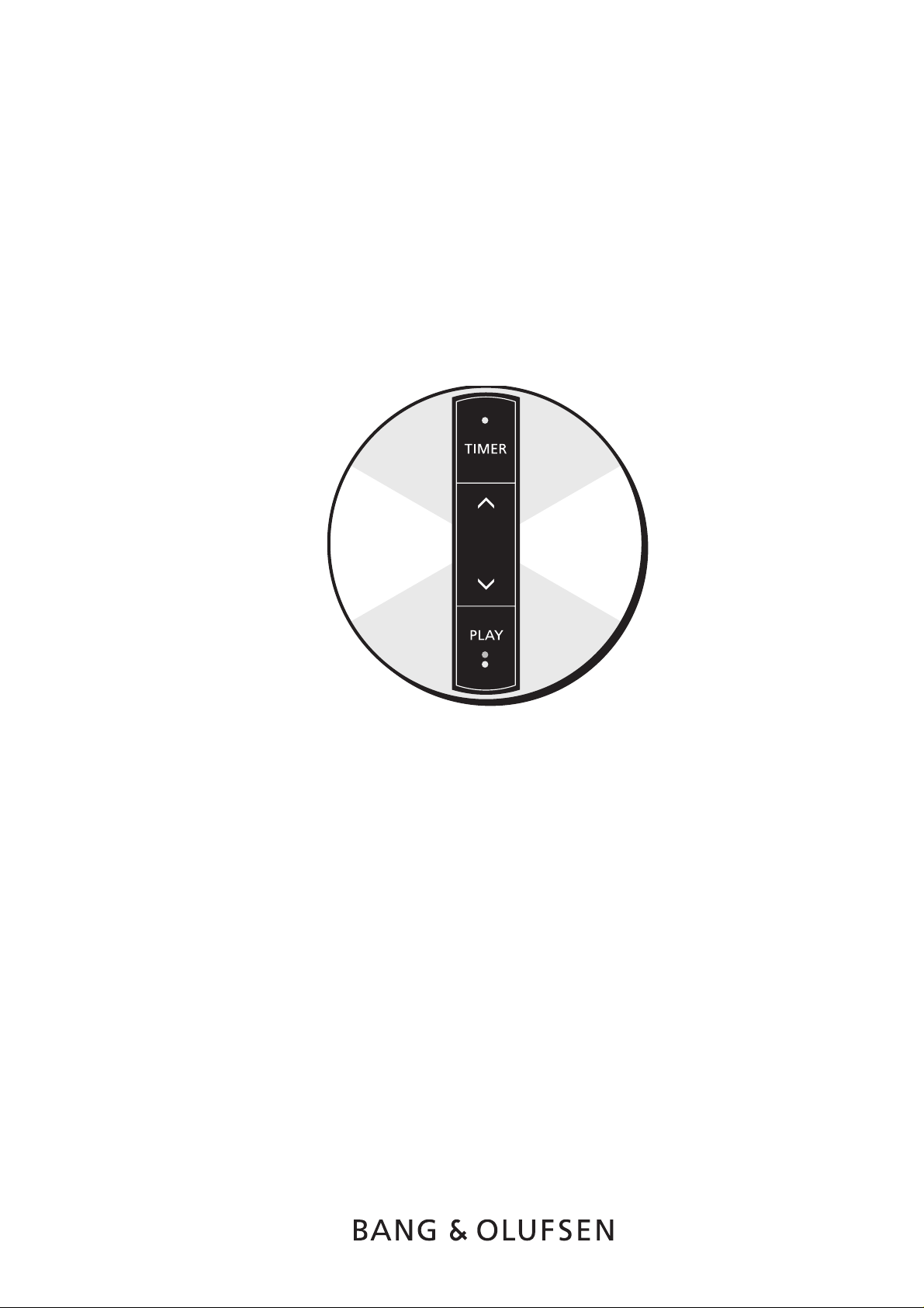
Timer on/off
Type number
Page 9
Timer on/off
Volume up/down:
Type number
3m
Page 10
Any type of Bang & Olufsen active loudspeaker can be connected. If you
the BeoLab 8000.
The sound adjustment facilitates individual adjustment of balance, bass,
treble and loudness.
Timer on/off
Volume adjustment
Type number
5m
1.5m
Page 11

function within a temperature range of 10-40º C. At temperatures outside
this range it can block the whole Master Link system if connected to one.
All Bang & Olufsen passive loudspeakers can be connected.
volume can be adjusted independently of the main room.
volume individually.
Timer on/off
Volume up/down:
Type number
5m
1.5m
Page 12

Video system in the main room. The other end of the coax cable connects
to the aerial socket of the link room TV.
3m
1.5m
watch and operate decoded programs from TV and SAT receivers in the
to the main room system via a Master Link cable. In addition there is a coax
Type number
Page 13

1.5m
videomaster. BeoLink Converter has autocon guration, which means that it
Type number
Page 14
1.5m
the main room, e.g. a BeoSound Ouverture.
Type number
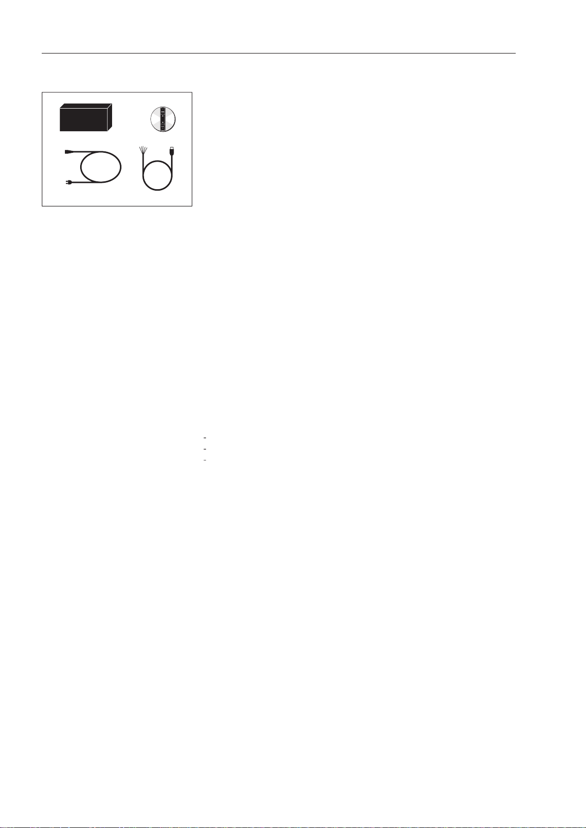
Jack
USB
Main
s
via a USB and jack plug cable. All connections are made to this box (Mains,
Type number
Page 15

A mechanism constructed using several components can generally only be
The point of the above is that you can only make things work properly by
This also applies to the Bang & Olufsen BeoLink system. In theory Bang &
totally impossible to gain an overview of even a fraction of the many
When planning a BeoLink system, it is therefore very important to adhere
to the recommended setups.
yourself in the same situation as that mentioned above, i.e having a gear
the products included in the setup "know" the type of system they form
The actual option programming is performed by entering a particular key
When you use Beo4, the programming sequences are as follows:
V
then
t
O
t
then
1
Page 16

When you use BeoLink 1000, the programming sequences are as follows:
"number"
"number"
"number"
The number selection depends on the setup.
Two IR receivers in the same main room
Two IR receivers in the same link room
with products that have been installed previously, e.g. in connection with a
factory.
Page 17

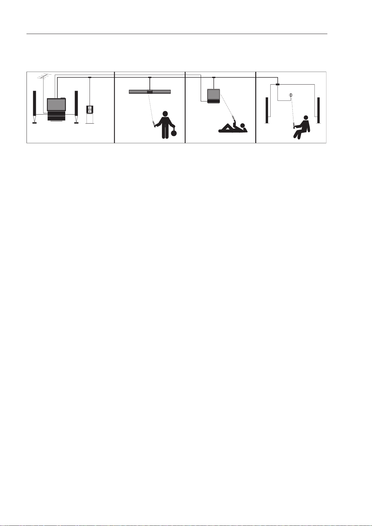
Audio system in one room
Video system in one room
AV system in one room
Master Link
Master
Link
AV system in two rooms
Master
Link
Master
Link
Master Link
Master
Link
Master Link
Master Link
Page 18

MASTER LINK
Master Link
Master Link
14
Recommended setups for one product in a link room
BeoLab 3500
Option programming : Ready for use
Factory programming : Option 6
BeoLab 2000
Option programming : Ready for use
Factory programming : Option 6
BeoVision MX 4200
Option programming : Option 6
Factory programming : Option 1
Master Link : Accessories
BeoLink Active
Option programming : Ready for use
Factory programming : Option 6
BeoLink Passive
Option programming : Ready for use
Factory programming : Option 6
Master Link
Master Link
Coaxial
Master Link
Page 19

MASTER LINK 15
BeoVision Avant
BeoVision option programming : Option 6
BeoVision factory programming : Option 1
BeoLink Video
BeoVision option programming : Option 6
BeoVision factory programming : Option 1
NOTE!
Information on options and programming for a BeoVision connected to
BeoLink Video can be found in Bang & Olufsen’s Product Configuration
Guide.
BeoSound 3000
BeoSound option programming : Option 6
BeoSound factory programming : Option 1
Master Link
Coaxial
Master Link
BeoLink PC2:
BeoLink option programming : Option 6
BeoLink factory programming : Option 6
Master Link
Master Link
BeoLin
k
Video
Datalink
Coaxial
Page 20

MASTER LINK16
Recommended setups for one audio and one video product in link rooms
1.
BeoLab/BeoLink option programming : Option 5
BeoLab/BeoLink factory programming : Option 6
BeoVision MX 4200 option programming : Option 5
BeoVision MX 4200 factory programming : Option 1
NOTE!
Information on options and programming for a BeoVision connected to
BeoLink Video can be found in Bang & Olufsen’s Product Configuration
Guide.
* NB:
Applies to all Audio link room products.
** NB:
Applies to Video link room products incl.
BeoLink Video
2.
BeoSound option programming : Option 5
BeoSound factory programming : Option 1
BeoVision Avant option programming : Option 5
BeoVision Avant factory programming : Option 1
Master Link
Coaxial
Master
Link
Master Link
Coaxial
Master
Link
Audio*
Video**
Page 21

Master
Link
Master
Link
Datalink
BeoLink
Converter
Power
Link
MCL
Master Link
Master
Link
BeoLink
Converter
Datalink
MCL
4.
Master Link
Master
Link
Datalink
BeoLink
Converter
Master Link
Datalink
BeoLink
Converter
Master Link
Datalink
BeoLink
Converter
AUX-
T-branch
Datalink
Page 22

Master Link
Master
Link
Datalink
BeoLink
Converter
with the BeoLink Converter can be found in Bang & Olufsen’s Product
Master Link
Master
Link
BeoLink
Converter
Datalink
MCL
Page 23

together with a new ML audio system in the main room.
Master
Link
MCL
Master Link
MCL
Master
Link
Master Link
MCL
BeoLink
Converter
Datalink
Master Link
Page 24

Apart from the recommended setups there are two further combinations.
They are not mentioned under recommended setups, as they do not fully
A.Tape, etc.), source control (winding and rewinding, step, track selection,
The link room product or link room kit in the main room
This setup is used when you want to have an extra sound zone in the main
Master Link
Master Link
Audio/video system
The AV system is operated as normal.
The extra sound zone only receives information from the remote control if
the LINK key is activated for source selection (Radio, CD,A. Tape etc.)
Page 25

4 only receives information from the remote control if the link key is
Main room
OPTION 1
OPTION
4
Link room
The BeoLink Video CANNOT be set to option 4!
Link room
Link room
OPTION 6
OPTION 4
All link room products and link room kits using the Master Link connection
Page 26
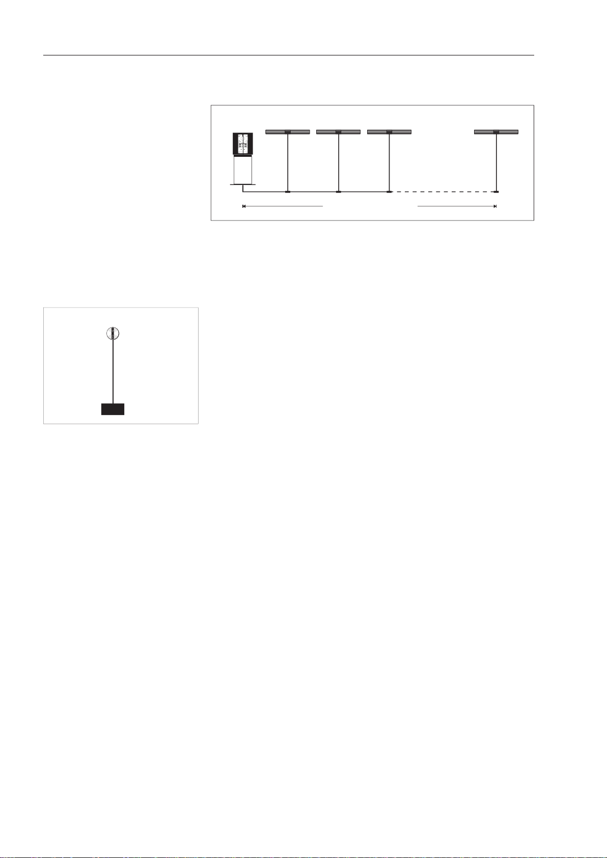
A BeoLink system using Master Link can consist of up to 16 rooms,
The cable between receiver and BeoLink Active must not exceed 5 metres
A special 15-metre low-capacity cable can be ordered, order no. 6270668.
Receiver cable
max. 5m
Max. 400m ML Cable
Page 27

ways of using Bang & Olufsen installation accessories, as described at the
The installations only show a couple of installation examples, but there is,
Visible installation
A visible installation is used when it is not possible to hide cables and
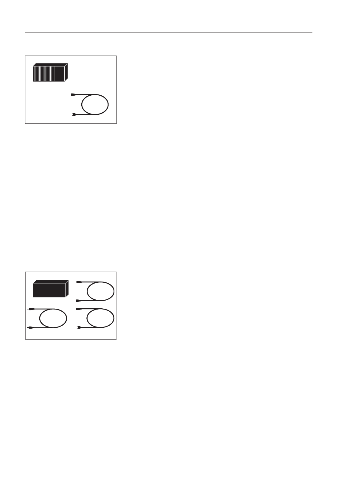
4 x Master Link cable with one plug
4.
walls and/or loft. In this example we have used:
4 x Master Link cable with two plugs
4 x Master Link wall socket
4.
Page 28

Another type of hidden installation is shown below. This type of
4 x Master Link cable with two plugs
4 x Master Link junction boxes
Aerial installation
Master Link
Aerial
Master Link
Aerial
Aerial installation with built-in aerial splitter.
Aerial installation with external aerial splitter.
Page 29

The incorporation kit for the IR receiver is used for invisible installations.
There are two types of incorporation kit.
The other kit is designed for partition walls (order. no. 3375188) and consists
Page 30
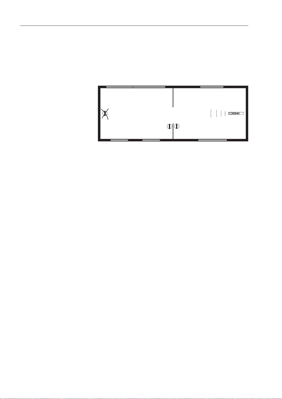
The receiver must be positioned so that there is nothing preventing the
When you decide where you want to position an IR receiver, you must
time by remote control.
Room 1
Room 2
1
3
2
The illustration shows that IR receiver 3 is correctly positioned, while
The receiver must not be positioned in direct sunlight or direct arti cial
the sensitivity of the receiver (= shorter remote control distance).
work at temperatures above 55º C or below 0º C. If there is a risk of the
temperature being outside this range, it must be possible to disconnect the
whole system.
that the person who is telephoning can easily mute the equipment.
The control box does not necessarily have to be positioned in the same
that the temperature may not exceed 40º C or fall below 10º C.
Page 31

visible installations, it can be desirable to use grey cabling along the walls,
Black
Grey
There can be a maximum of 4 ML cables per junction box.
Page 32

BeoLink Passive
BeoLink Active
BeoLink Video
Cupboard orbasement orattic
As can be seen from the illustration you can position BeoLink boxes centrally.
temperature. See section on "Dimensioning", page 22, and "Positioning of
The BeoLink boxes are designed for use within a temperature range of
®
/IHC Net
®
®
/IHC Net
®
installation you can use this
Video distribution must, however, always be via a coaxial cable installed
®
/IHC Net
®
installation, as the latter does not
®
/IHC Net
®
wall
®
/
®
The actual distribution is performed on the main panel, in exactly the same
way as all other signals transmitted in a LexCom Home
®
/IHC Net
®
from your local installation retailer.
The total length of the cable carrying the Master Link signal must not
®
/IHC Net
®
installation cables.
A maximum of 10 loudspeakers (5 sets) may be connected to each Power
®
/IHC Net
®
Page 33

ML
ML
MasterLink BO 100-ML MasterLink BO 100-ML
PowerLink BO 100-PL
Data Switch S100-T
Te
le T100
Pwr Link/Data
Link/Data
Uplink 12 3 4
1 2 3 4
Antenne T110
Master Link
Master Link
Power Link
TeleAntenne Data Switch
1 2 3 4 5 6 7 8 91011 12
13
14 15 16 17 18 19 20 21
22
23 24 25 26
®
/IHC Net
®
main panel – Master Link
the appropriate patch port.
to patch port.
4. Go back to the wall socket and
18
18
13
14
11
12
15
1
6
17
18
13
14
11
12
15
16
17
18
18
Symbol
ML
Page 34

®
/IHC Net
®
main panel – Power Link
the appropriate patch port.
to set the Left/Right button on
the loudspeakers.
22
17
18
15
16
19
2
0
21
22
17
18
15
16
19
20
21
22
22
Symbol
PL1
22
Page 35

1
2
3
4
5
6
7
8
9
10
11
12
13
14
15
16
PI
GN
WH/
GN
WH/
BL
OR
WH/
OR
WH/
RD
RD
BL
white
shield
grey
pink
green
shield
brown
yellow
shield
shield
grey
white
7
1
2
3
4
5
6
8
7
1
2
3
4
5
6
8
Power Link cable with core for display data
white/green (WH/GN)
white/blue (WH/BL)
4-10
white/orange (WH/OR)
white/red (WH/RD)
TECHNICAL DESCRIPTION
The following section contains a short description of the cable installations
Master Link cable
yellow
yellow
white
white
Page 36

Power Link cable without core for display data
7
1
2
3
4
5
6
8
7
1
2
3
4
5
6
8
shield
shield
yellow
green
brown
21-pin A/V cable with RGB connection
4
xed blanking, ground
xed blanking
video out, ground
video out, set
video out, signal (Y out)
video in, signal (Y in)
1
2
3
6
4
15
13
11
9
7
5
16
18
20
17
19
8
21
10
12
14
21
19
17
15
20
18
16
13
11
14
12
9
7
10
8
6
5
4
3
2
1
2
1
6
3
4
15
13
11
9
7
5
16
17
19
18
20
8
21
10
12
14
Datalink cable
7
1
2
3
4
5
6
7
1
2
3
4
5
6
shield
green
blue
white
red
yellow
black
yellow
yellow
white
white
Coax cable
yellow
yellow
Page 37

Receiver cable
1
5
4
3
2
Yellow
4
White
All Bang & Olufsen products in the
the power source during
MKIII
MKIII
Shields from
wires without
insulation
Seen from solderside
Green 5
Brown 3
Ye
llow 4
Blue 7
2
6
1
4
2
5
3
7
8
Page 38

TROUBLESHOOTING
Datalink
Datalink
BeoLink
Converter
Master Link
More than 20m
The isolation method is the rst course of action when troubleshooting a
nd out if the fault is in the main room or the link rooms. Then connect
the link rooms one by one until the fault is discovered. This is a quick way
tester allows you to localise faults very quickly in the individual cores of the
junction box you do not need to create the short circuit. The short circuit
faults can arise: All link audio functions work, but link video functions do
Page 39

video jams (red bar on the shield), humming in the front loudspeakers,
we recommend creating a ground connection from here.
All speci cations are measured to ground using an oscilloscope.
The following speci cations apply to Master Link:
white/green
white/blue
4 - 10
voltage
voltage
white/orange
white/red
Master Link
Aerial
Page 40

The product is connected to mains and the stand-by LED is illuminated.
When there is no transmission the reading should be between +/- 200
When data is being transmitted it should read 0V.
———————————— + 0.25 V
———————————— 0 V
———————————— - 0.25 V
Transmission
to transmit, there may be a fault in the main room BeoVision or BeoSound,
The fault is found using the isolation method. If the fault is not in one of
the Master Link drivers, there is another unit pulling data either low or
0.3V
0V
-0.3V
Data+
Data-
mS
with the link room product, possibly the converter box, cables or a
volume
Page 41

this is not the same as saying there is a fault with the actual product where
the fault message appears.
you can access service mode and the possibilities provided by service mode.
The example of service mode below is from BeoLab 3500.
Address con guration is impossible.
too many units connected to the Master Link.
them one by one other until the fault appears. Disconnect the product
This fault can arise if there is no Master Link driver circuit, or as a result of a
tips for a description of the data receiver circuit.
The data traf c on the Master Link has been unusually high, or a product is
Page 42

21-pin AV cable/SCART
The control unit or audiomaster in component-based audio systems, e.g
A remote control which operates the products by sending a command to
them without requiring a response back (e.g. BeoLink 1000 and Beo4).
There are basically two types of main room:
Two room setups: audio and video systems in two different rooms.
video recorder. The cable is speci ed for RGB signal transmission.
Audio Aux Link
Audio Aux Link is the name of the 7-pin Datalink connection between the
AV setup
AV system
Audio/video system Integration of audio and video where there is only one
Page 43

Ability to combine products from different seasons and with different
All products with a Master Link socket.
The products that need to be option programmed must be on stand-by.
they are part of so that they can be operated and function optimally.
A PC-based tool that makes it possible to compose the desired product
type without data signals for display readout (4-pin) The latter cannot be
Page 44

40
This LED tester consists of two boxes and two Master Link cables.
The main box connects to the Master Link system. When turned on, the
The LED box can then be connected to the remaining Master Link
the pulses through the individual cores. This enables you to easily see if
there is a circuit in all cores and thus locate the defective link (e.g. junction
The illustration shows typical Master Link system connections. We will use
this system as an example to show how the LED tester tests the Master Link
Page 45

All products must be disconnected during the test, as it would otherwise be
junction boxes). The small extra cables supplied can be used if you suspect
that a cable between a product and a wall socket is faulty.
Page 46

ACCESSORIES
white
42
Page 47

AUX T-plug
43
Page 48

than 5 m cable is required.
terminal block f. MCL) (4)
tting
tted on a wall.
Page 49

White
Wall socket
Wall socket with Master Link socket.
Wall socket, 8-pin DIN
Wall socket with 8-pin DIN bushing
with solder terminals.
49 x 49 x 24 mm, white (DK)
49 x 49 x 24 mm, grey (DK)
white
45
Page 50

Wall socket base. Used for tting on
49 x 49 mm wall socket,
white (DK)
49 x 49 mm wall socket,
white (EURO)
for recessed tting in brick or plaster
walls.
49 x 49 x 24 mm, grey (DK)
49 x 49 x 24 mm, white (DK)
transceiver.
walls.
46
Page 51

wall socket (with blanking cap).
white
47
Tools
wall socket
junction box
Page 52

48
®
/IHC Net
®
Adapter from B&O Power Link to
®
/IHC Net
®
white
white
white
white
®
/IHC Net
®
Adapter from B&O Master Link to
®
/IHC Net
®
white
white
white
white
with bag
Page 53

49
Adjustment wheel (1)
 Loading...