

Bang Olufsen Beolab 9 Service Manual

BeoLab 9
Type 6217
Service Manual
English
German, French, Italian, Spanish, Danish, Dutch and Japanese versions
are available in the Retail System
This Service Manual must be returned
with the defective parts/back-up suitcase !

CONTENTS
Survey of modules .................................................................... 1.1
How to service .......................................................................... 1.2
Fault flow chart ......................................................................... 2.1
Adjustments ............................................................................. 3.1
Repair tips ................................................................................. 3.2
Final check after repair .............................................................. 3.3
Replacement of modules ........................................................... 4.1
Specification guidelines for service use ...................................... 5.1
Block diagram ........................................................................... 6.1
Wiring diagram ......................................................................... 6.3
Available parts .......................................................................... 7.1
4
999
7
3
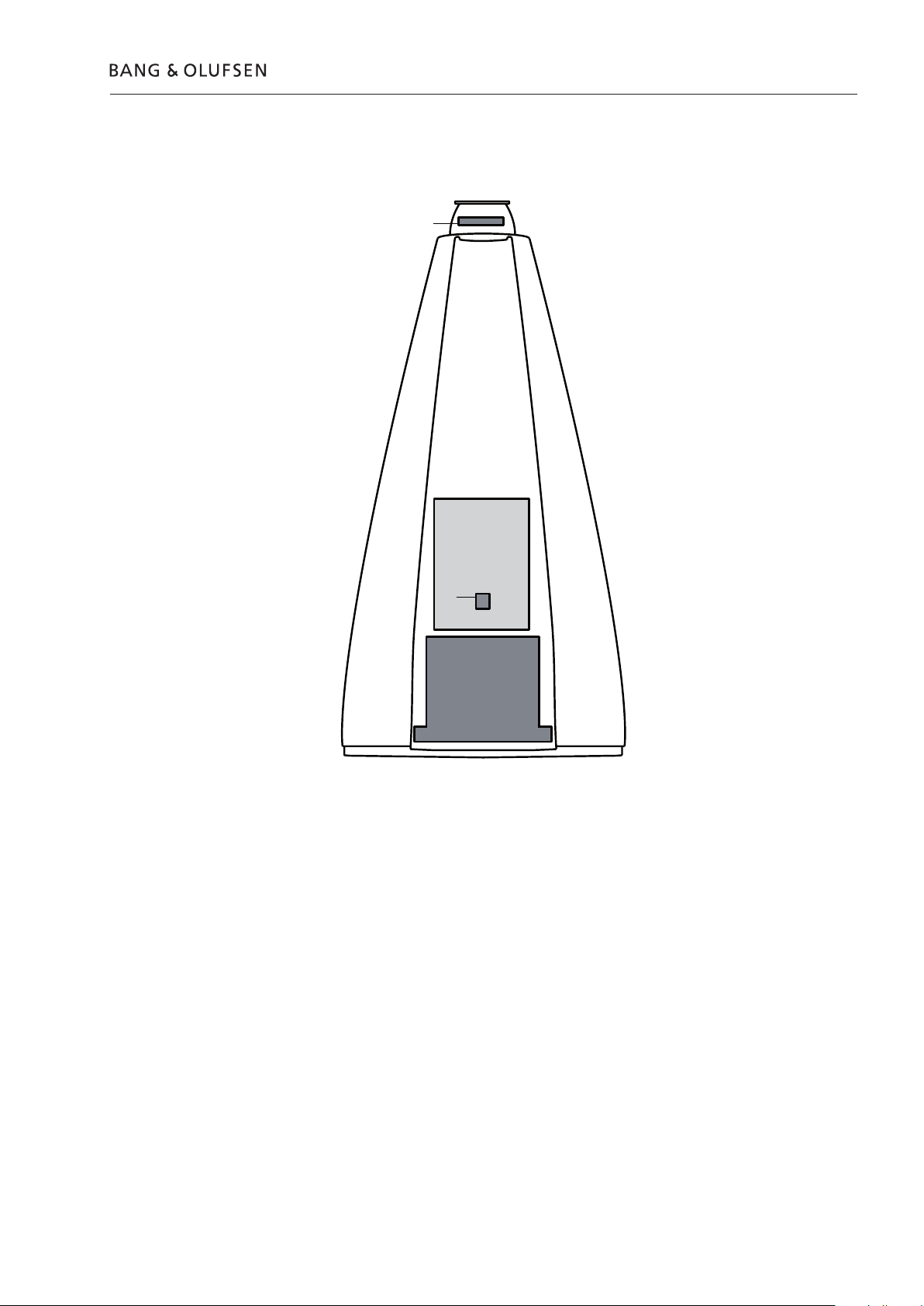
Survey of modules
Survey of modules 1.1
PCB1 Cross Over
PCB2 LC-Filter
PCB3 LED
PCB4 Power Supply
PCB5 ICEpower Amplifier
PCB7 NTC
999Module Chassis complete, incl. PCB1, PCB2, PCB5

1.2 How to service
How to service
Strategy
BeoLab 9 has been split-up into as few service items as possible. Each servicefriendly item is packed individually, prepared for worldwide transport, and has a
separate seven digit spare part number to be found in the Bang & Olufsen Retail
System or the Service Manual. An exploded view drawing shows the service spare
parts.
The back-up suitcase holds all necessary electrical modules for front-line repair of
one loudspeaker in e.g. the customers home.
Cabinet parts must be brought with you separately, if to be replaced in the
customers home.
An adequate fault description must be returned with each replaced part. For this
purpose, use the Module Repair form or the form in the Retail Order System under
Exchange Module. To help the Bang & Olufsen Module Repair department it is
very important to answer the following questions:
1. Which products are in the setup?
2. Which software versions are used in these products?
3. How are the products linked together?
4. What happens in the actual situation?
Preparations before service
Fault explanation and demonstration
Recommended tools for service
All service repair will be on module level by means of the back-up suitcase.
Service Manuals in other languages can be found in the Retail System as PDF-files.
Always remember to download the latest version of the Service Manual.
Fault description must be returned with the replaced parts.
Use the Module Repair form or the form in the Retail Order System, Exchange
Module.
Before troubleshooting is initiated, let the customer demonstrate the fault, if
possible.
White gloves.
Soft lint-free cloth.
Multimeter.
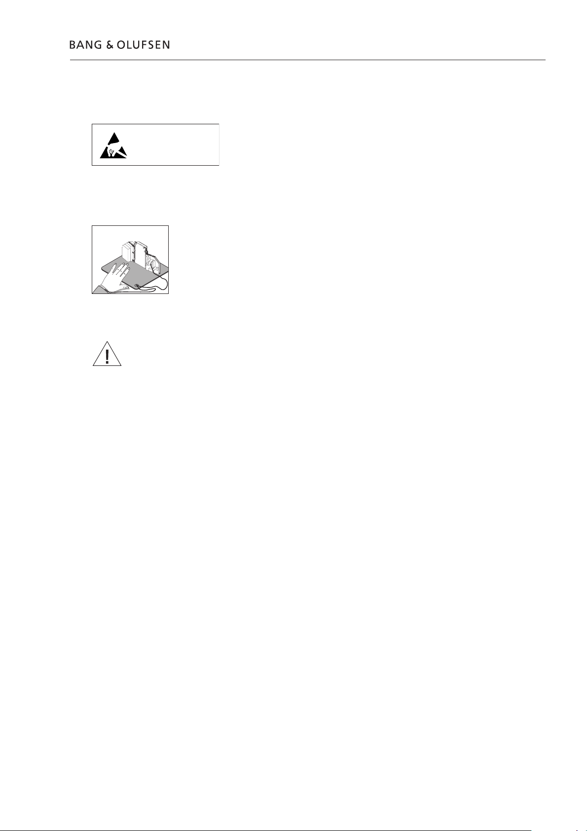
Handling and cleaning
STATIC ELECTRICITY
MAY DESTROY THE
PRODUCT
ESD
Static electricity
How to service 1.3
Static electricity may damage the product.
Static-protective field service kit.
A static-protective field service kit must always be used when the product is
disassembled or modules are being handled.
Follow the instructions in this Service Manual and use the ESD-mat for both old
and new modules.
Please note:
When mains voltage on the product is required, remove the connection between
the product and the ESD-mat.
The chassis or modules must always be connected to the static-protective field
service kit or placed in an ESD-proof bag.
Symbol of safety components
Transport and handling
Cleaning
When replacing components with this symbol, the same type has to be used, also
the same values for ohm and watt.
The new component is to be mounted in the same way as the replaced one.
It is recommended to:
- use the product cover when transporting the product.
- do not move the product when it is operating.
Please refer to the chapter “Final check after repair” or the User’s guides.

1.4

Fault flow chart
Fault flow chart 2.1
No red light in STANDBY ...................................................... 2.2
No sound, but green LED is OK ............................................ 2.4
No sound from woofer, but tweeter and midrange is OK ..... 2.4
No sound from midrange, but tweeter and woofer is OK ..... 2.5
No sound from tweeter, but midrange and woofer is OK ..... 2.5
No function of the PCB7, NTC ............................................. 2.6
No function of S1 and S2 ..................................................... 2.6
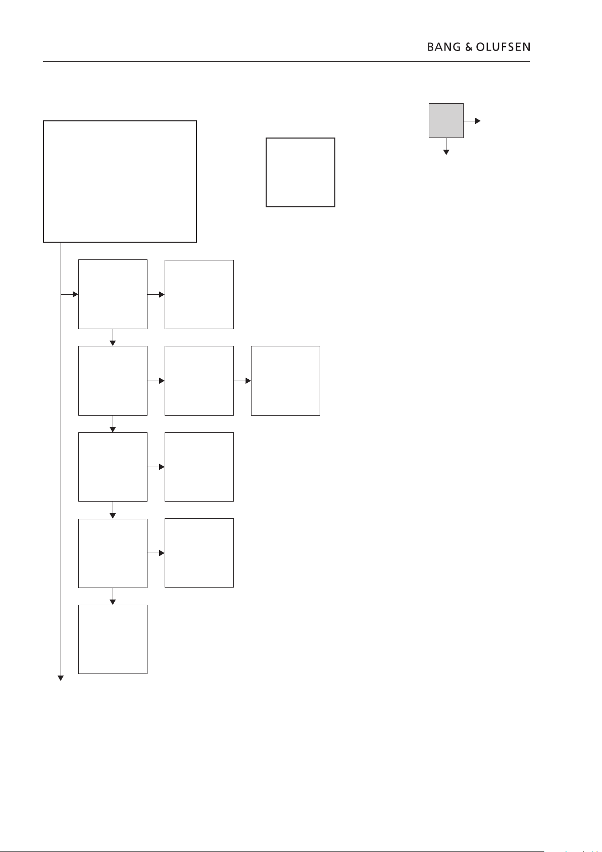
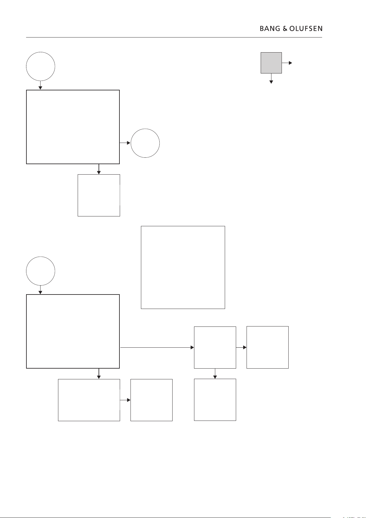
2.2 Fault flow chart
Fault symptom:
- No red light in STANDBY
Possible causes:
- Fuse F1
- PCB4, Power Supply
- Module 999, Amplifier
Connect a Master Link cable from e.g. a
BeoSound 4, to BeoLab 9. Make sure that S101
is set to either L or R. Connect mains to BeoLab 9.
Is there red light in the LED on top of BeoLab 9?
Note:
Ground is
chassis
No
Yes
Confirm mains in the
mains wire
Confirm mains on
PCB4, Power Supply
P13 pin1 and 2
Confirm 5V on PCB4,
Power Supply P14
pin1
Confirm 4.2V on
PCB1, Cross Over P9
pin 2
Reconnect mains
If possible, check fuse
F1 on PCB1, Cross
Over
Replace PCB4, Power
Supply
Replace Module 999,
Amplifier
Replace fuse F1
Replace PCB3, LED
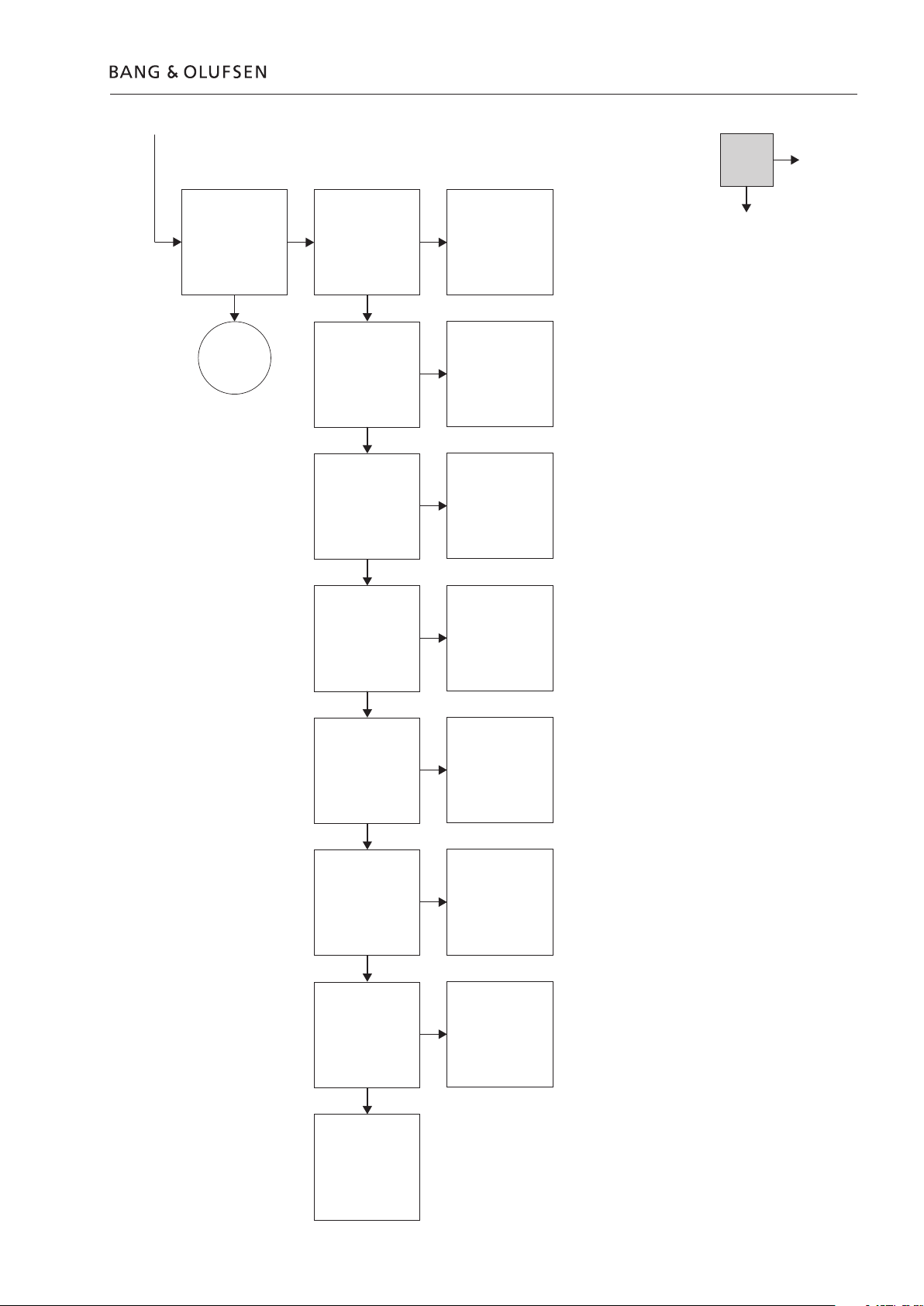
Fault flow chart 2.3
No
Select e.g. Radio or
CD on the
Audiomaster, and
press GO on Beo4
Does BeoLab 9 turn
on (Green light in
LED)
Go to
next page
Confirm 5V on PCB4,
Power Supply P14 pin
7
Confirm -12V on
PCB4, Power Supply
P14 pin 3
Confirm 12V on
PCB4, Power Supply
P14 pin 5
Confirm 44V on PCB4,
Power Supply P15
pin 4
Check Power Link
cable and
Audiomaster.
Reconnect/replace if
nescessarry.
(This is not covered in
this fault flow chart)
Replace PCB4, Power
Supply
Replace PCB4, Power
Supply
Replace PCB4, Power
Supply
Yes
Confirm -44V on
PCB4, Power Supply
P15 pin 5
Confirm 66V on
PCB4, Power Supply
P15 pin 6
Confirm approx 4.7V
on PCB4, Power
Supply P14 pin 9
Replace Module 999,
Amplifier
Replace PCB4, Power
Supply
Replace PCB4, Power
Supply
Replace PCB4, Power
Supply
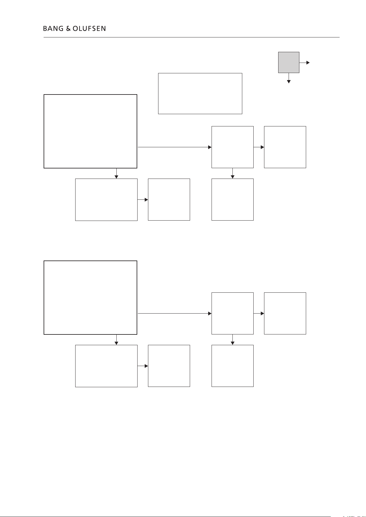
2.4 Fault flow chart
From previous
page
Fault symptom:
- No sound, but green LED is OK
Possible causes:
- Module 999, Amplifier
Is there no sound, but the green LED is OK?
Replace Module 999,
Amplifier
From above
Fault symptom:
- No sound from woofer, but tweeter and
midrange is OK
Possible cause:
- Woofer
- Module 999, Amplifier
Turn volume on the Audio Master up to 50.
Confirm an AC-Sound signal by means of the
Bar-graph on the multimeter or an oscilloscope,
when measuring across the woofer input
terminals.
Go to box
further down
on page
Note:
It wil give the best result if it is possible to
use an audio test CD with pure sine waves
and an oscilloscope, when measuring on
the woofer or midrange.
Warning:
Be very careful, when measuring on the
woofer, because there is approx 35Vdc on
both input terminals. Make sure to use a
differential probe, or make sure that the
oscilloscope and the product is not
connected to earth.
Visual confirm cable
connection between
woofer and Module
999, Amplifier
No
Yes
Reconnect/replace
cable
Remove mains from the
product. Remove the black wire
from the woofer. Measure the
resistance across the woofer
terminals:
Approx 2.9 ohm?
Replace woofer
Replace Module 999,
Amplifier
Fault flow chart 2.5
No
Fault symtom:
- No sound from midrange, but tweeter and
woofer is OK
Possible cause:
- Midrange
- Module 999, Amplifier
Turn volume on the Audio Master up to 50.
Confirm an AC-Sound signal by means of the
Bar-graph on the multimeter or an oscilloscope,
when measuring across the midrange input
terminals.
Remove mains from the
product. Remove the black
wire from the midrange.
Measure the resistance across
the midrange terminals:
Approx 6.1 ohm?
Note:
It wil give the best result if it is possible to
use a audio test CD with pure sine waves
and an oscilloscope, when measuring on
the woofer or midrange
Visual confirm cable
connection between
midrange and Module
Replace midrange
Replace Module 999,
999, Amplifier
Amplifier
Yes
Reconnect/replace
cable
Fault symtom:
- No sound from tweeter, but midrange and
woofer is OK
Possible cause:
- Tweeter
- Module 999, Amplifier
Turn volume on the Audio Master up to 50.
Confirm an AC-Sound signal by means of the
Bar-graph on the multimeter or an oscilloscope,
when measuring between PCB1, Cross Over
P10 pin 1 and ground.
Remove mains from the
product. Remove the connector
on PCB1, Cross Over P10.
Measure the resistance
between the orange and white
wire:
Approx 6.6 ohm?
Replace tweeter
Visual confirm cable
connection between
tweeter and Module
999, Amplifier
Replace Module 999,
Amplifier
Reconnect/replace
cable
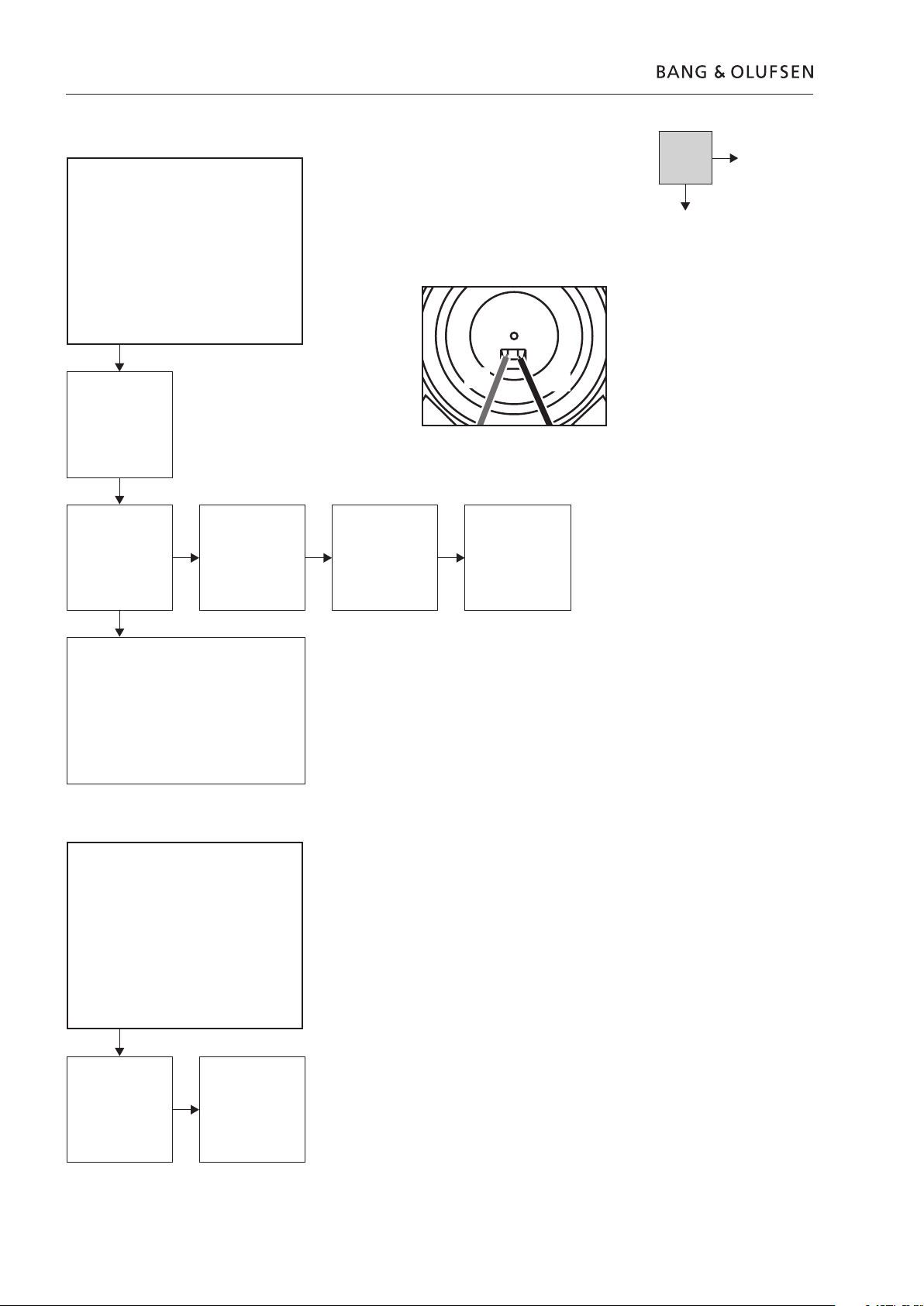
2.6 Fault flow chart
No
Fault symptom:
- No function of the PCB7, NTC
Possible cause:
- PCB7, NTC
- Cable W4
- Module 999, Amplifier
Is the loudspeaker in
protection mode?
Visual confirm cable
connection between
Module 999, Amplifier
and PCB7, NTC
To confirm correct operation of the NTC, measure
approx. 9.35V DC at normal room temperature, as
shown in fig 1
(When the temperature is rising, the DC voltage is
going towards 0)
When the loudspeaker goes into protection mode,
it is nescessarry to disconnect mains and wait one
minute before connecting it again.
Reconnect/replace
cable
Note:
Replace PCB7, NTC
Fig1
Red
Replace Module 999,
Black
Amplifier
Yes
Fault symptom:
- No function of S1 and S2
Possible cause:
- Module 999, Amplifier
Is there no function of
switch S1 and/or S2?
Replace Module 999,
Amplifier
 Loading...