


CH-4
Bakers Pride CH-4, CH-6, CH-10, CH-8, CH-16 Operation Manual
...
OPERATION MANUAL
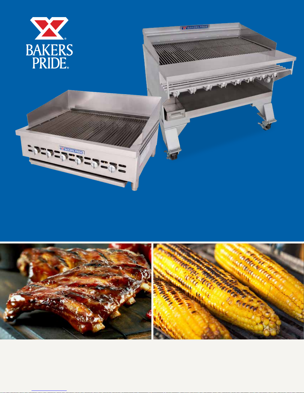
DANTE SERIES GAS CHARBROILERS
SERIES: XX & CH
BUILT BY CRAFTSMEN. TESTED BY TIME®.
XX & CH CHARBROILER OPERATION MANUAL
CHARBROILER OPERATION MANUAL
Models:
Dante XX & CH
Bakers Pride Oven Company, LLC is a wholly owned
subsidiary of Standex International Corporation.
All gas operated Bakers Pride® charbroilers are intended
for use with the type of gas specified on the rating plate
and for installation will be in accordance with National
Fuel Gas Code ANSI Z223.1 (latest edition).
WARNING
FOR YOUR SAFETY: Do not store or use gasoline
or other flammable vapors or liquids in the vicinity
of this or any other appliance.
WARNING
After the gas supply has been connected to your
unit, it is extremely important to check piping
for possible leaks. To do this, use soap and water
solution or solutions which are expressly made
for this purpose. DO NOT USE matches, candles,
flames, or other sources of ignition since these
methods are extremely dangerous.
Post in a prominent location instructions to be
followed in the event you smell gas. Obtain these
instructions from your local gas supplier.
WARNING
Improper installation, adjustment, alteration,
service or maintenance can cause property
damage, injury or death. Read the installation,
operating and maintenance instructions
thoroughly before installing or servicing this
equipment.
WARNING
Instructions must be posted in a prominent
location. All safety precautions must be taken in
the event the user smells gas. Safety information
can be obtained from your local gas supplier.
Please retain this manual for future references.
This equipment is design engineered for commercial
use only.
This equipment has been engineered to provide
you with year round dependable service when used
according to the instructions in this manual and
standard commercial kitchen practices.
Phone: 800.527.2100 | Fax: 914.576.0605 | www.bakerspride.com
BAKERS PRIDE OVEN COMPANY, LLC.
1307 N. Watters Rd., Suite 180
Allen, TX 75013
P/N U46023A 06/17
TABLE OF CONTENTS
DANGER
WARNING
CAUTION
NOTICE
XX & CH CHARBROILER OPERATION MANUAL
GENERAL DESCRIPTION 2
INSTALLATION 2
CLEARANCES 2
GAS CONNECTION 2
BURNERS 2
RADIANTS 3
TOP GRATES 3
LIGHTING 3
GRIDDLE PLATES 3
ADDITIONAL INSTALLATION REQUIREMENTS 4
INSTALLATION WITH CASTERS 4
OPTIONAL SMOKER BASE 4
OPERATING INSTRUCTIONS 5
LIGHTING PROCEDURE 5
BROILING PROCEDURE 5
SEASONING 5
STEAKS AND CHOPS 5
HAMBURGERS 5
THICKNESS 5
COOKING TOOLS 5
OPERATIONAL GUIDELINES FOR CHARBROILER 5
NATURAL SMOKE ESSENCE 5
HELPFUL HINTS 6
MAINTENANCE 6
SERVICE 6
CARE AND CLEANING OF TOP GRATES 6
GREASE COLLECTION 6
CLEANING TOOLS 6
AVERAGE PRODUCTION GUIDE 7
TROUBLESHOOTING GUIDE 7
BURNER FLAME ADJUSTMENT 7
PILOT FLAME ADJUSTMENT 7
LACK OF HEAT 7
ONE BURNER FAILS TO LIGHT 8
TROUBLESHOOTING CHART 8
VALVE ASSEMBLY VIEWS 9
PARTS LISTS & EXPLODED VIEWS 10
MODELS: XX-4, -6, -8, -10 & 12
PARTS LISTS & EXPLODED VIEWS 10
MODELS: CH-6, -8, -10, -12 & 14
PARTS LIST & EXPLODED VIEW 13
SAFETY PRECAUTIONS
This symbol warns of imminent hazard which will
result in serious injury or death.
This symbol refers to a potential hazard or unsafe
practice, which could result in serious injury or
death.
WARRANTY 15
This symbol refers to a potential hazard or unsafe
practice, which may result in or moderate injury or
product or property damage.
This symbol refers to information that needs
special attention or must be fully understood even
though not dangerous.
1
XX & CH CHARBROILER OPERATION MANUAL
CAUTION
NOTICE
INSTALLATION INSTRUCTIONS
General:
The instructions in this manual apply to all XX series and
CH series Broilers.
The XX series may include the following options:
Ceramic briquettes designated by a GS Suffix on the
model number.
Installation:
(a) In USA, INSTALLATION of this broiler must
conform with the latest edition of the National Fuel
Gas Code, ANSI Z223.1 and/or local codes.
(b) In CANADA, INSTALLATION must conform with
the latest edition of the National Gas Installation
Code, CAN/CGA-B149.1 or the Propane
Installation Code, CAN/CGA-B149.2, as applicable
and/or local codes.
(c) In MASSACHUSETTS, All gas products must be
installed by a “Massachusetts” licensed plumber
or gas fitter. Ventilation hoods must be installed in
accordance with NFPA-96, current edition, with
interlocks as described in that standard.
For units using propane gas, supply lines less than
1/2” inside diameter should not be used, even for a
small unit.
On the XX and CH series, the gas connection is located
on the right rear of the unit.
Be sure to cap whichever side is not connected.
A shut-off valve in a readily accessible location
must be mounted on the gas supply line before
the unit.
When making gas pipe connections, pipe joint
compound resistant to the action of liquefied petroleum
gases should be used.
The broiler and its individual shutoff valve must be
disconnected from the gas supply piping system during
any pressure testing of that system at test pressures in
excess of 1/2 psig (3.45 kPa).
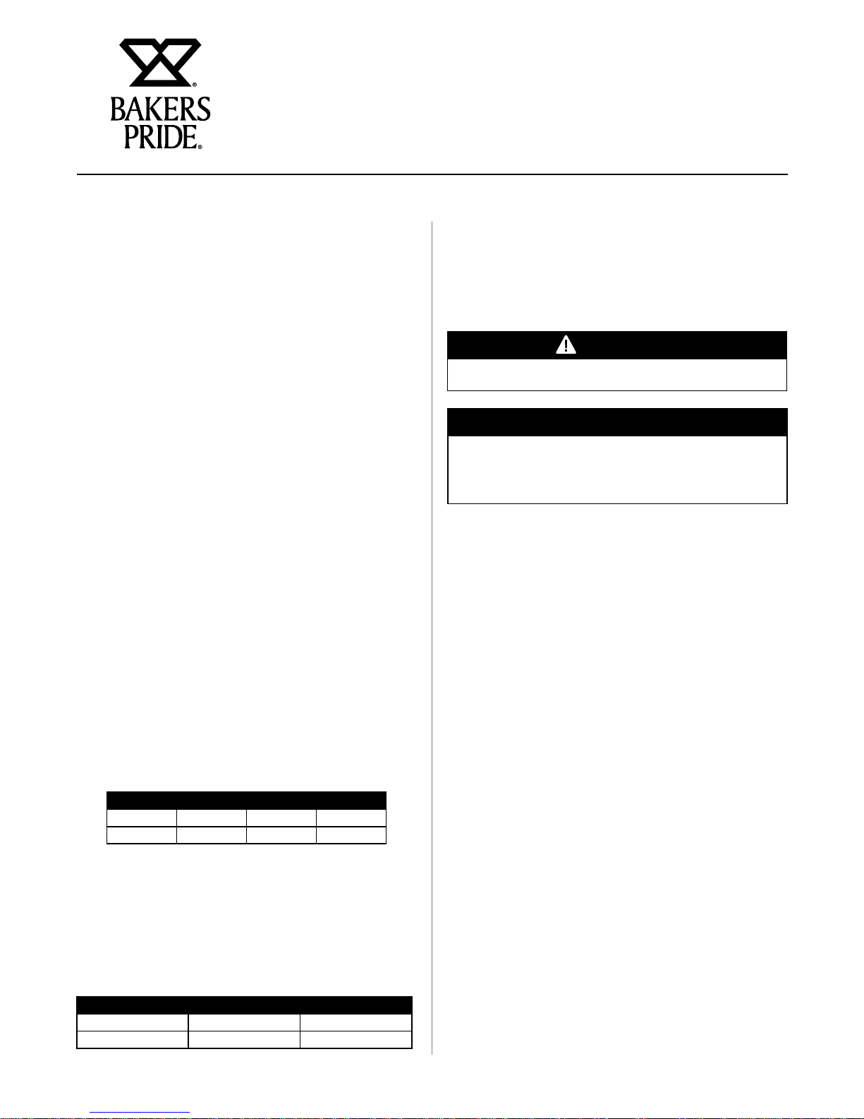
Acceptable Clearances:
Due to intense heat generated by radiation, these
broilers should be installed in non-combustible locations
only including above the grate level.
Minimum Clearance From Non-Combustible
Construction.
Series Right Left Back
XX 0” 0” 0”
CH 0” 0” 0”
Gas Connection:
The gas pressure regulator supplied must be installed
at the gas inlet of each broiler. Each regulator is
adjusted to yield a manifold pressure of 5 in. water
column for natural gas or 10 in. water column for
propane gas. No pressure regulator is required for
propane gas in Canada.
Recommended minimum gas supply lines are listed below
All XX Models CH-4 thru CH-8 CH-10 thru CH-16
3/4” 1” 1 1/2”
The broiler must be isolated from the gas supply piping
system by closing its individual manual shutoff valve
during any pressure testing of the gas supply piping
system at test pressures equal to or less than 1/2 psig
(3.45 kPa).
Burners:
Check to see that AIR MIXER CAPS on the front of
all burners are tightened and adjusted, allowing half
the opening to show. Install the burners and deflector
shields first following the steps below.
(a) Install all burners with deflector shield assemblies
attached.
(B) Place the front of the burner into the valve
assembly by fitting the center hole of the mixer
cap over the brass orifice.
(c) Drop the rear end of the burner over the burner
support pin on the back of the unit.
2
XX & CH CHARBROILER OPERATION MANUAL
NOTICE
INSTALLATION INSTRUCTIONS
Radiants:
Mount the “V” shaped radiants over the burners with
each end mounted on special supports on the front and
rear of the chamber. A radiant should be mounted over
each burner assembly.
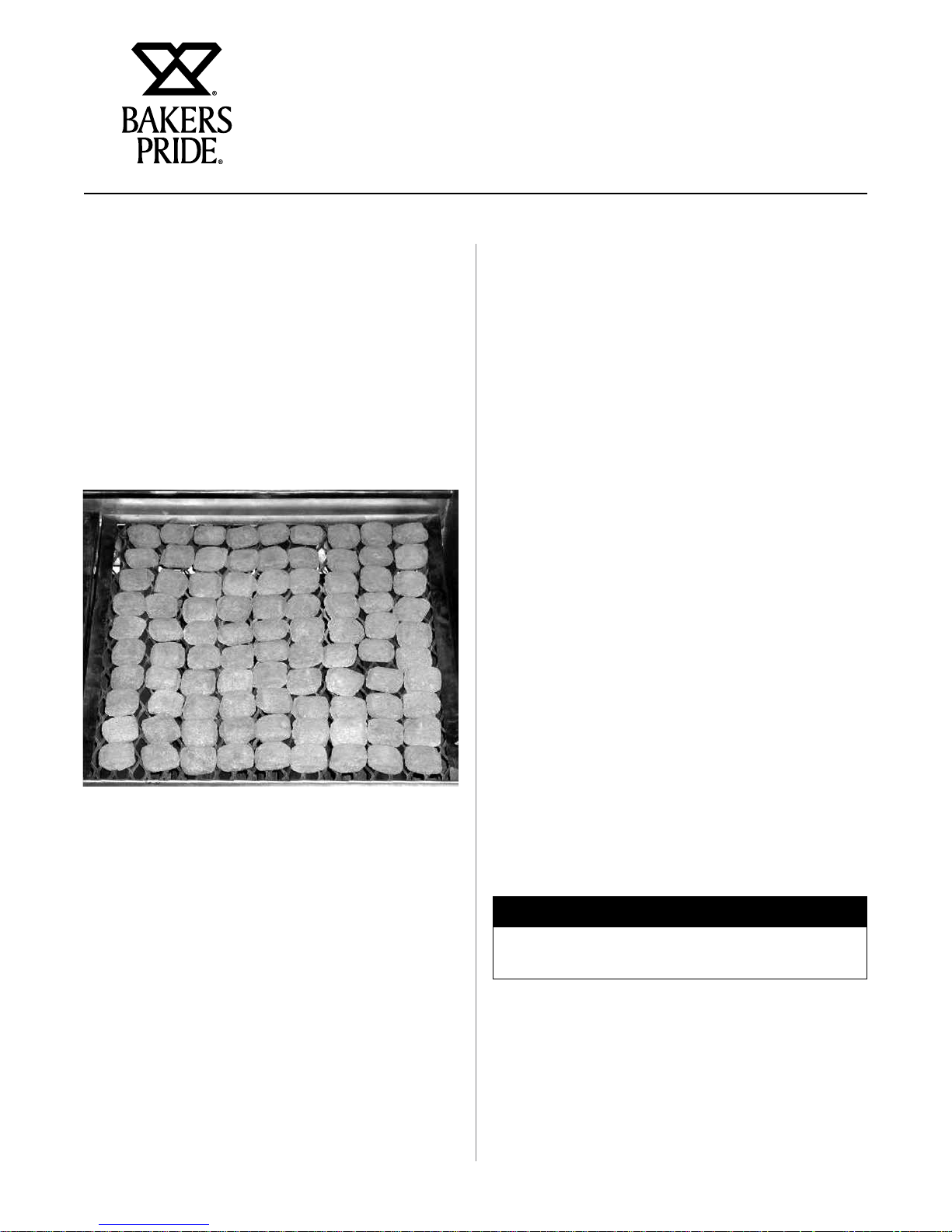
GS Ceramic Briquettes Option:
The radiants supplied for the GS option are flattened to
allow for the installation of an expanded metal grate. The
grate is installed directly on top of the flattened radiant
burner shield. Ceramic briquettes are installed on the
grate as shown:
Lighting:
Each burner on the base charbroiler has a standing pilot
burner that must be lit before the burners can be lit. To
light the pilot burners:
(a) Turn all broiler valves to the off position.
(b) Remove each top grate and radiant.
(c) Open main gas SHUT-OFF valve (supplied by
customer).
(d) Allow air to bleed from the gas line through the
pilot burners.
(e) Light the pilot burners using a lit taper.
(f) Turn the burner control valves “ON” to light the
burners.
(g) If any burner fails to light, turn the burner valves
to “OFF”, wait five minutes and repeat the above
procedure.
(h) After all burners have been ignited properly, turn
each burner valve “OFF” and allow the unit to cool.
NOTE: Make sure that the pilot burners stay lit.
Figure 1: Typical Ceramic Briquette Installation
Top Grates:
Place a grate over each of the radiants. For normal
operation, the pointed side of the grate is facing up. For
use with foods that require extra support, the flat side
may be used.
On XX Models, grates can be placed on three levels;
two positions are built into the rear of the unit; the third
position requires a special adapter. On CH models, three
positions are already built into the rear of the unit.
(i) Replace radiants and top grates.
(j) Each burner may now be adjusted to the desired
flame size by turning the individual burner valve
handle.
(k) To shut down the unit, turn all valves “OFF”
Wait five minutes before attempting to re-light.
The pilot burners will stay lit until the gas supply
to the unit is turned “OFF”.
Griddle Plate:
Griddle plates should not cover more than 50% of the
BROILING area. Each Griddle Plate fits on top of two
grates (one 4 1/2” and one 6”). It is not necessary to
remove the top grates and radiants before installing the
griddle plate.
3
XX & CH CHARBROILER OPERATION MANUAL
INSTALLATION INSTRUCTIONS
Additional Installation Instructions
(a) Keep the area around the broiler free and clear of
combustible materials.
(b) The provision of an adequate air supply to your
broiler is essential. Provide for sufficient outside
air to enter the broiling area and assure that this
airflow is not obstructed.
(c) Air enters the burner area from the front and
bottom of your broiler. Assure that these areas are
kept open and unobstructed.
(d) Servicing is accomplished through the front and
top of the broiler. Assure that these areas are kept
unobstructed for proper servicing and operation.
Installation With Casters
(a) Install the casters with the wheel brakes on the
front of the appliance.
(b) Installation should be made with a connector that
complies with the latest edition of the Standard
for Connectors for Movable Gas Appliances, ANSI
Z21.69 in the USA (CAN/CGA-6.16 in Canada),
and a quick disconnect device that complies
with the latest edition of the Standard for Quick
Disconnect Devices for use with gas fuel, ANSI
Z21.41 in USA (CAN 1-6.7 in Canada) and
adequate means must be provided to limit the
movement of the appliance without depending
upon the connector and any quick disconnect
device or its associated piping to limit the
appliance movement.
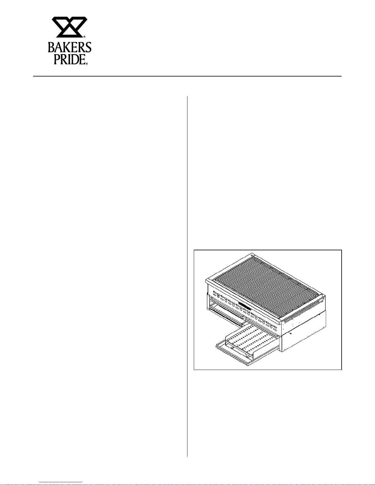
Optional Smoker Base
Installation
(a) Remove the grease pans from their rails completely
and set aside.
(b) Unscrew to remove the legs from the broiler.
Discard.
(c) Set the broiler into the base unit. The frame will
fit into the lip around the top of each side and the
back.
(d) Install the #10 self-threading sheet metal screws
around the base into the broiler frame to hold
in place. Each screw requires a 5/32 hole to be
drilled into the broiler frame.
(e) Get the grease pan(s) previously set aside. Insert
a log holder into each pan. Slide the pan into the
bottom of the base.
(c) The restraint should be attached to the legs on
which the casters are mounted.
(d) If disconnection of the restraint is necessary,
the restraint should be reconnected after the
appliance has been returned to its originally
installed position.
4
 Loading...