

Bake Max CO5TG, CO5TE Installation And Operation Manual
Convection Oven
Installation
Operation
CO5TG
MODELS
CO5TE
Manual
and
INDEX
1. INTRODUCTION
2. ADVANTAGES
3. IMPORTANT NOTES
4. INSTALLATION REQUIREMENTS
5. GAS INSTALATION INSTRUCTIONS
6. ELETRIC INSTALATION INSTRUCTIONS
7. TWO STAGE OPENING DOOR
8. CLEANING
9. TECHNICAL DATA
10. MAINTENANCE
11. DIGITAL CONTROLLER
12. OPERATION
13. ELETRIC SCHEMATICS
14. EXPLODED VIEW / PARTS LIST
15. PARTS LIST CO5TG
16. EXPLODED VIEW CO5TE
17. PARTS LIST CO5TE
WARRANTY TERM
3
3
3
4
5
9
10
10
11
11
12
12
13
14
15
16
17
18
FOR YOUR SAFETY
Do not store or use gasoline or other flammable vapors or
liquids in the vicinity of this or any other appliance.
WARNING
Improper installation, adjustment, alteration, service, operation or maintenance can cause property
damage, injury or death. Read the installation, operating and maintenance instructions thoroughly
before installing, operating or servicing this equipment.
NOTICE
Instructions must be posted in a prominent location that will provide the user of this equipment with
procedures, in the event he/she smells and/or detects gas. This information must be obtained by
consulting the local gas utility.
WARNING
Electrical Grounding Instructions
This appliance is equipped with a three-prong (grounding) plug for your protection
against shock hazard and should be plugged directly into a properly
grounded three-prong receptacle. Do not cut or remove tie grounding prong from this plug.
3
The Convection Oven is another innovation BAKEMAX offers you, being a versatile and indispensable equipment for various types
of businesses, and we are sure that it will be of great value to your establishment. Use this guide for more details regarding the
functioning of the Convection Oven. Despite the ease of use, the information contained here in is very important for you to get the
maximum performance and to avoid problems.
Keep these instructions because it will be very helpful to answer questions and ensure the proper operation and
maintenance of the equipment.
-- Modern and innovative design with double glass door with two-stage opening, consisting of one (1) curved outer glass and one
(1) internally, which reduces the temperature of the outer surface and easy access for cleaning.
- Internal monoblock Chamber type with removable stainless steel handles and pigmented enamel finishing with high durability,
facilitating cleaning.
- Tray capacity of 5 full size sheet pans 18" x 26" pans.
- Differentiated handle with great grip, low heat conductivity and facilitates the opening and closing of the door, making practical
handling.
- Easy to operate digital controller with the functions timer, temperature and steam.
- Uses 6500W armored resistance that provides excellent cooking with low consumption. (Electric model - CO5TE).
- Lower gas consumption due to heating being taken directly from the burner to the interior of the cooking chamber, thus getting a
better performance (Gas model - CO5TG).
- The door has a silicone sealing, developed for efficient sealing, as well as easy removal.
- Stand is optional.
- This appliance is not intended to be used by people (including children) with reduced physical, sensory or mental capacities, or
people with lack of experience and knowledge, unless they have received instructions regarding the use of the device or under the
supervision of a someone responsible for their safety. They should make arrangements so that children do not play with the
equipment.
- The Convection Oven Gas (CO5TG) is manufactured in model NATURAL GAS, with optional for GLP (propane gas), with the voltage
being 240V.
- The Electric Convection Oven(CO5TE) is only available in 240V voltage with 6500W resistance.
- Do not store explosive substances, such as aerosol, or any flammable propellant in this appliance.
- During operation, the equipment should always be monitored and can not be in operation without the presence of qualified
people.
- Sanitize the product daily after use, with a mild detergent and a sponge, without using abrasive materials. Never use water jets for
cleaning the product, as this may damage the electrical system.
- The power to the oven should not be provided using a residual current device (RCD) with a residual operating current rating no
higher than 30mA, or install a DR circuit breaker in the protective framework of the establishment, with a capacity of residual current
lower than 30 mA, in order to prevent accidents due to discharged voltage leakage in the equipment frame.
- The installation of this appliance must conform to local codes or, in the absence of local codes, with the National Fuel Gas Code
ANSI Z223.1 Natural Gas Installation Code, CAN/CGA-B149-1 or the Propane Installation Code, CAN/CGA-B149-2 as applicable,
including:
1. The appliance and its individual shut off valve must be disconnected from the gas supply piping system during any pressure
testing of that system at test pressure in excess of 1/2 psi (3.45 kPa).
2. The appliance must be isolated from the gas supply piping system by closing the individual manual shut off valve during any
pressure testing of the gas supply piping system.
- The appliance, when installed, must be wired and electrically grounded in accordance with local codes, or in the absence of local
codes, with the National Electric Code, ANSI/NFPA 70, or the Canadian Electrical Code, CSA C22.2 as applicable.
Installation, Operation and Service Personnel - Installation of the equipment should be performed by qualified, certified, licensed
and/or authorized personnel who are experienced in state/local installation codes.
Operation of the equipment should be performed by qualified or authorized personnel who have read and understand this manual
and are familiar with the functions of the equipment.
- Service of the equipment should be performed by qualified and licensed service personnel who are knowledgeable with BakeMax
products.
1. INTRODUCTION
2. ADVANTAGES
3. IMPORTANT NOTES
4
UNPACKING
1. Remove all packaging and transit protection including all
protective plastic coating from the exterior stainless steel
panels.
2. Check the oven and supplied parts for damage. Report any
damage immediately to the carrier and distributor.
3. Check that the following parts have been supplied with your
oven:-
4. Report any deciencies to the distributor who supplied your
oven.
5. Check that the available electrical supply is correct to that
shown on the Technical Data Plate located on the front right hand
side panel.
LOCATION
1. Position the oven in its approximate working position.
2. The unit should be positioned so that the control panel
and oven shelves are easily reachable for loading and
unloading.
CLEARANCES
To ensure correct ventilation for the motor and controls, the following minimum installation clearances are to be adhered to:
Top 8. 20/ 0 mm
Rear 300mm / 12.
Left-hand side 450mm / 18.
Right-hand side 900mm / 36.
· Installation shall comply with local elec trical, health and safety requirements.
· It is most important that this oven is installed correctly and that oven operation is correct before use.
· If you have any questions regarding the proper installation and
/ or operation of this oven, please contact your local
distributor.
Qualied installation personnel are individuals, a rm or a company which either in person or through a representative are engaged
in and responsible for the installation of electrical wiring from the electric meter, main control box or service outlet to the electric
appliance.
Qualied installation personnel, licensed and bonded, must be experienced in such work, familiar with all precautions required and
have complied with all requirements of state or local authorities having jurisdiction.
U.S. and Canadian Installations - All ovens, when installed, must be electrically grounded in accordance with local codes, or in the
absence of codes, with the National Electrical Code ANSI/NFPA 70 - Latest Edition and/or Canadian National Electrical Code C22.2
as applicable.
The ventilation of these ovens should be in accordance with local codes. In absence of local codes, refer
to the national ventilation code titled, Standard for the Installation of Equipment for the Removal of
Smoke and Grease Laden Vapors from Commercial Cooking Equipment, NFPA-96-Latest Edition.
The appliance is to be installed with a check valve in accordance with applicable federal, province and local codes.
CO5TG
Manual
LPG Orice Hood
3/4" Water Hose
3/4" x 1/2" Reduction
Regulator Valve
CO5TE
Manual
3/4" Water Hose
4. INSTALLATION REQUIREMENTS
IMPORTANT

5. GAS INSTALLATION INSTRUCTIONS
THIS APPLIANCE IS INTENDED FOR OTHER THAN HOUSE HOLD USE
All BakeMax commerical gas appliances are manufactured by skilled craftsman using the finest quality materials.
PROPER installation by qualified personnel is essential for safe, efficient, and trouble-free operation of the unit. Any alteration and/or
tampering, without proper knowledge, tools, and test equipment, is DANGEROUS and will void all warranties. The installation must
conform with local codes, or in the absence of locel codes, with the National Fuel Gas Code, ANSIZ223.1- latest edition.
PRESSURE TESTING: FAILURE TO INSTALL PRESSURE REGULATOR WILL VOID WARRANTY.
(Most units have a convertible regulator.) The appliance and its indivdual shut-off valve must be disconnected from the gas supply
piping system during any pressure testing of that system at test pressure in excess of 1/2 psig (3.45 kPa). The appliance must be isolated
from the gas supply piping system by closing its individual manual shut-off valve during any pressure testing of the gas supply piping
system at test pressures equal to or less than 1/2 psig (3.45 kPa).
NOTICE
The proper installation of this gas appliance is the total responsibility of the end user. It is the responsibility of the purchaser to
determine that the installer is qualified in installation procedures. Conversion, connecting gas lines, calibrating thermostats, burners,
lighters, setting gas pressure with manometer, and etc., is all part of normal installation and will not be paid for under warranty. If a
warranty technician is called out and finds the unit improperly installed, the end user may be subject to billing.
FOR MAINTENANCE, SERVICE, REPAIRS, OR INSTALLATION - Contact your dealer or the factory, for your local Factory Authorized
Service Agency.
The gas pressure regulator provided with the equipment must be installed when the appliance is connected to the gas supply.
The area around the appliance must be kept free and clear of combustibles such as solvents, cleaning liquids, brooms, rags, etc.
Proper clearances must be provided at the front of the appliances for servicing and proper operation.
Provisions shall be incorporated in the design of the kitchen, to ensure an adequate supply of fresh air and adequate clearance for
air operanings into the combustion chamber, for proper combustion and ventilation.
For proper operation of the appliance, do not obstruct the ow of combustion and ventilation air.
The installation must conform with local codes, or in the absence of local codes, with the national fuel gas code, ANSI Z223.1 - 1988
(or latest addenda).
The gas supply line must be at least 3/4" NPT.
5
INSTALLATION - GAS STANDARDS AND CODES
1. The appliance and its individual shut o valve must be disconnected from the gas supply piping system during any pressure testing
of that system at test pressure in excess of 1/2 psi (3.45 kPa).
2. The appliance must be isolated from the gas supply piping system by closing the individual manual shut-o valve during any
pressure testing of the gas supply piping system at test pressures equal to or less than 1/2 PSI.
IMPORTANT - The installation of this appliance must conform to local codes or, in the absence of local codes, with the National Fuel
Gas Code ANSI Z223.1, Natural Gas Installation Code, CAN/CGA-B149-1, or the Propane Installation Code, CAN/CGA-B149-2 as
applicable, incluiding:
GAS CONNECTION - The gas inlet line size of this appliance is 3/4" NPT. For proper operation, the gas supply service line must be
the same size or greater than the inlet line size of the appliance. The gas line size must not be reduced at any point along the
supply line.
MANUAL SHUT - OFF V ALVE - A gas pressure regulator and a contractor-supplied shut-o valve must be plumbed in the gas service
line ahead of the appliance in a physical location where it can be reached quickly in the event of an emergency .
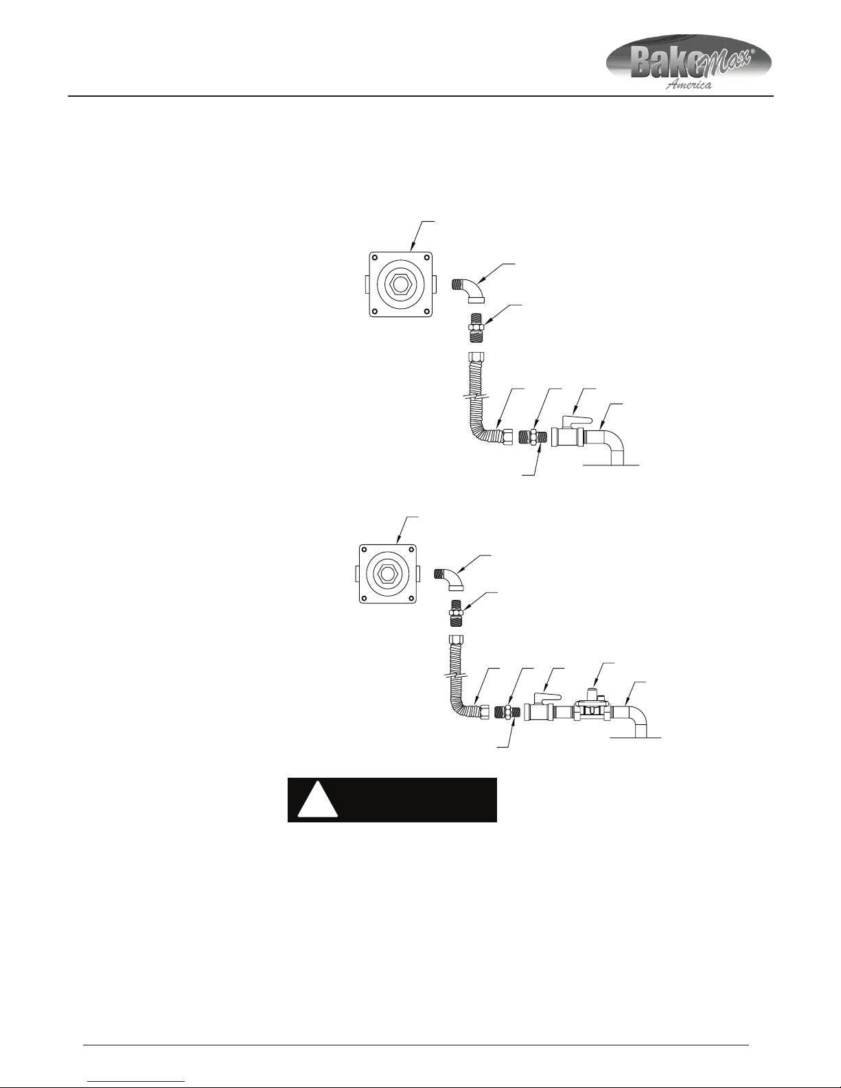
A. Gas pressure regulator
A
D C E
F
G
C
B
GAS
B. 90º Street elbow
C. Adapter (must be 3/4" male pipe thread)
D. Flexible connector
E. Manual gas shut-off valve
F. 3/4" gas supply
G. Use pipe-joint compound
NATURAL
Visually double check any installer-supplied intake pipes and/or blow them out using compressed air to clear any dirt or debris,
threading chips, or other foreign matter before installing a service line. Those particles will clog gas orices when gas pressure is
applied. Compounds used on threaded joints of this appliance piping must be resistant to the action of NG and LP gas and provide
a gas tight seal to prevent leaks.
When installing the pressure regulator - remember it can only handle 1/2 PSI. In e very LPG installation, you have high source pressures,
ranging from 20 PSI to 100 PSI. If the high pressure gas line from the LPG tank is directly connected to the unit without the proper
step-down regulator, it will rupture the diaphragm in the valve, rendering it useless.
!
WARNING
The gas pressure regulator must be installed in the gas line failure to install a pressure regulator will void the equipment warranty.
The regulators supplied with ranges have 3/4" NPT connections; the regulator is adjusted at the factory for 4" W.C. (water column)
manifold gas pressure (natural gas) or 10" W.C. manifold gas pressure for propane gas operation.
B
C
G
F
ECD
A
A. Gas pressure regulator
B. 90º Street elbow
C. Adapter (must be 3/4" male pipe thread)
D. Flexible connector
E. Manual gas shut-off valve
F. 3/4" gas supply
G. Use pipe-joint compound
H. Step down regulator
H
LP GAS
6
 Loading...