

Page 1
Valve Positioners
RCV SRD991 Intelligent Positioner
POS-UM-00010-EN-03 (August 2014)
User Manual
Page 2

Valve Positioners, RCV SRD991 Intelligent Positioner
Page ii August 2014POS-UM-00010-EN-03
Page 3

User Manual
CONTENTS
Device Features . . . . . . . . . . . . . . . . . . . . . . . . . . . . . . . . . . . . . . . . . . . . . . . . . . . . . . . . . . . . . . . . . . . . . . 7
With Communication . . . . . . . . . . . . . . . . . . . . . . . . . . . . . . . . . . . . . . . . . . . . . . . . . . . . . . . . . . . . . . . . 7
Without Communication. . . . . . . . . . . . . . . . . . . . . . . . . . . . . . . . . . . . . . . . . . . . . . . . . . . . . . . . . . . . . . 7
Common Features . . . . . . . . . . . . . . . . . . . . . . . . . . . . . . . . . . . . . . . . . . . . . . . . . . . . . . . . . . . . . . . . . . 7
Labels. . . . . . . . . . . . . . . . . . . . . . . . . . . . . . . . . . . . . . . . . . . . . . . . . . . . . . . . . . . . . . . . . . . . . . . . . . . . . 8
Unpacking & Inspection . . . . . . . . . . . . . . . . . . . . . . . . . . . . . . . . . . . . . . . . . . . . . . . . . . . . . . . . . . . . . . . . . 9
Safety Information. . . . . . . . . . . . . . . . . . . . . . . . . . . . . . . . . . . . . . . . . . . . . . . . . . . . . . . . . . . . . . . . . . . . . 9
Accident Prevention. . . . . . . . . . . . . . . . . . . . . . . . . . . . . . . . . . . . . . . . . . . . . . . . . . . . . . . . . . . . . . . . . 9
Electrical Safety. . . . . . . . . . . . . . . . . . . . . . . . . . . . . . . . . . . . . . . . . . . . . . . . . . . . . . . . . . . . . . . . . . . . 9
Summary – Hart and 4-20 mA without Communication . . . . . . . . . . . . . . . . . . . . . . . . . . . . . . . . . . . . . . . . . . . . . 9
Mounting to Actuator (Valve) . . . . . . . . . . . . . . . . . . . . . . . . . . . . . . . . . . . . . . . . . . . . . . . . . . . . . . . . . . . 9
Connection and Startup . . . . . . . . . . . . . . . . . . . . . . . . . . . . . . . . . . . . . . . . . . . . . . . . . . . . . . . . . . . . . . 9
System Conguration. . . . . . . . . . . . . . . . . . . . . . . . . . . . . . . . . . . . . . . . . . . . . . . . . . . . . . . . . . . . . . . 10
Summary – Foundation Fieldbus . . . . . . . . . . . . . . . . . . . . . . . . . . . . . . . . . . . . . . . . . . . . . . . . . . . . . . . . . . 11
Connection and Startup . . . . . . . . . . . . . . . . . . . . . . . . . . . . . . . . . . . . . . . . . . . . . . . . . . . . . . . . . . . . . 11
Bus Connection. . . . . . . . . . . . . . . . . . . . . . . . . . . . . . . . . . . . . . . . . . . . . . . . . . . . . . . . . . . . . . . . . . . 11
System Integration. . . . . . . . . . . . . . . . . . . . . . . . . . . . . . . . . . . . . . . . . . . . . . . . . . . . . . . . . . . . . . . . . 11
Summary – Probus-PA . . . . . . . . . . . . . . . . . . . . . . . . . . . . . . . . . . . . . . . . . . . . . . . . . . . . . . . . . . . . . . . . 12
Mounting to Actuator (Valve) . . . . . . . . . . . . . . . . . . . . . . . . . . . . . . . . . . . . . . . . . . . . . . . . . . . . . . . . . . 12
Connection and Startup . . . . . . . . . . . . . . . . . . . . . . . . . . . . . . . . . . . . . . . . . . . . . . . . . . . . . . . . . . . . . 12
Bus Connection. . . . . . . . . . . . . . . . . . . . . . . . . . . . . . . . . . . . . . . . . . . . . . . . . . . . . . . . . . . . . . . . . . . 13
System Integration. . . . . . . . . . . . . . . . . . . . . . . . . . . . . . . . . . . . . . . . . . . . . . . . . . . . . . . . . . . . . . . . . 13
Summary – FoxCom (Digital) . . . . . . . . . . . . . . . . . . . . . . . . . . . . . . . . . . . . . . . . . . . . . . . . . . . . . . . . . . . . . 14
Mounting to Actuator (Valve) . . . . . . . . . . . . . . . . . . . . . . . . . . . . . . . . . . . . . . . . . . . . . . . . . . . . . . . . . . 14
Connection and Startup . . . . . . . . . . . . . . . . . . . . . . . . . . . . . . . . . . . . . . . . . . . . . . . . . . . . . . . . . . . . . 14
System conguration . . . . . . . . . . . . . . . . . . . . . . . . . . . . . . . . . . . . . . . . . . . . . . . . . . . . . . . . . . . . . . . 14
Method of Operation . . . . . . . . . . . . . . . . . . . . . . . . . . . . . . . . . . . . . . . . . . . . . . . . . . . . . . . . . . . . . . . . . . 15
General . . . . . . . . . . . . . . . . . . . . . . . . . . . . . . . . . . . . . . . . . . . . . . . . . . . . . . . . . . . . . . . . . . . . . . . . 15
Block Diagram . . . . . . . . . . . . . . . . . . . . . . . . . . . . . . . . . . . . . . . . . . . . . . . . . . . . . . . . . . . . . . . . . . . 16
Operation . . . . . . . . . . . . . . . . . . . . . . . . . . . . . . . . . . . . . . . . . . . . . . . . . . . . . . . . . . . . . . . . . . . . . . 16
Operating Modes . . . . . . . . . . . . . . . . . . . . . . . . . . . . . . . . . . . . . . . . . . . . . . . . . . . . . . . . . . . . . . . . . . . . 17
Initialize . . . . . . . . . . . . . . . . . . . . . . . . . . . . . . . . . . . . . . . . . . . . . . . . . . . . . . . . . . . . . . . . . . . . . . . 17
Device Fault . . . . . . . . . . . . . . . . . . . . . . . . . . . . . . . . . . . . . . . . . . . . . . . . . . . . . . . . . . . . . . . . . . . . . 17
Page iii August 2014 POS-UM-00010-EN-03
Page 4

Valve Positioners, RCV SRD991 Intelligent Positioner
In Operation. . . . . . . . . . . . . . . . . . . . . . . . . . . . . . . . . . . . . . . . . . . . . . . . . . . . . . . . . . . . . . . . . . . . . 17
Failsafe . . . . . . . . . . . . . . . . . . . . . . . . . . . . . . . . . . . . . . . . . . . . . . . . . . . . . . . . . . . . . . . . . . . . . . . . 17
Out of Service . . . . . . . . . . . . . . . . . . . . . . . . . . . . . . . . . . . . . . . . . . . . . . . . . . . . . . . . . . . . . . . . . . . . 17
Calibrate . . . . . . . . . . . . . . . . . . . . . . . . . . . . . . . . . . . . . . . . . . . . . . . . . . . . . . . . . . . . . . . . . . . . . . . 18
Message . . . . . . . . . . . . . . . . . . . . . . . . . . . . . . . . . . . . . . . . . . . . . . . . . . . . . . . . . . . . . . . . . . . . . . . 18
Simulate (Foundation Fieldbus Version Only) . . . . . . . . . . . . . . . . . . . . . . . . . . . . . . . . . . . . . . . . . . . . . . . . 18
Functional Designations . . . . . . . . . . . . . . . . . . . . . . . . . . . . . . . . . . . . . . . . . . . . . . . . . . . . . . . . . . . . . . . . 19
Pneumatic Accessories . . . . . . . . . . . . . . . . . . . . . . . . . . . . . . . . . . . . . . . . . . . . . . . . . . . . . . . . . . . . . . 20
Mounting to Actuators . . . . . . . . . . . . . . . . . . . . . . . . . . . . . . . . . . . . . . . . . . . . . . . . . . . . . . . . . . . . . . . . . 21
NAMUR Mounting Linear Actuator, Left Side . . . . . . . . . . . . . . . . . . . . . . . . . . . . . . . . . . . . . . . . . . . . . . . . 21
NAMUR Mounting Linear Actuator, Right Side . . . . . . . . . . . . . . . . . . . . . . . . . . . . . . . . . . . . . . . . . . . . . . . 24
Linear Actuator, Direct Mounting . . . . . . . . . . . . . . . . . . . . . . . . . . . . . . . . . . . . . . . . . . . . . . . . . . . . . . . 27
Mounting to Rotary Actuators . . . . . . . . . . . . . . . . . . . . . . . . . . . . . . . . . . . . . . . . . . . . . . . . . . . . . . . . . 30
Pneumatic Connections . . . . . . . . . . . . . . . . . . . . . . . . . . . . . . . . . . . . . . . . . . . . . . . . . . . . . . . . . . . . . . . . 33
Electrical Connection . . . . . . . . . . . . . . . . . . . . . . . . . . . . . . . . . . . . . . . . . . . . . . . . . . . . . . . . . . . . . . . . . . 34
Options. . . . . . . . . . . . . . . . . . . . . . . . . . . . . . . . . . . . . . . . . . . . . . . . . . . . . . . . . . . . . . . . . . . . . . . . . . . 36
Limit Switch . . . . . . . . . . . . . . . . . . . . . . . . . . . . . . . . . . . . . . . . . . . . . . . . . . . . . . . . . . . . . . . . . . . . . 36
Additional Inputs / Outputs . . . . . . . . . . . . . . . . . . . . . . . . . . . . . . . . . . . . . . . . . . . . . . . . . . . . . . . . . . . 37
Built-in Pressure Sensors . . . . . . . . . . . . . . . . . . . . . . . . . . . . . . . . . . . . . . . . . . . . . . . . . . . . . . . . . . . . . 38
Startup . . . . . . . . . . . . . . . . . . . . . . . . . . . . . . . . . . . . . . . . . . . . . . . . . . . . . . . . . . . . . . . . . . . . . . . . . . . 39
General . . . . . . . . . . . . . . . . . . . . . . . . . . . . . . . . . . . . . . . . . . . . . . . . . . . . . . . . . . . . . . . . . . . . . . . . 39
Setting by Means of Local Keys . . . . . . . . . . . . . . . . . . . . . . . . . . . . . . . . . . . . . . . . . . . . . . . . . . . . . . . . . 39
Operation . . . . . . . . . . . . . . . . . . . . . . . . . . . . . . . . . . . . . . . . . . . . . . . . . . . . . . . . . . . . . . . . . . . . . . . . . 40
After Power ON . . . . . . . . . . . . . . . . . . . . . . . . . . . . . . . . . . . . . . . . . . . . . . . . . . . . . . . . . . . . . . . . . . . 40
In Operation. . . . . . . . . . . . . . . . . . . . . . . . . . . . . . . . . . . . . . . . . . . . . . . . . . . . . . . . . . . . . . . . . . . . . 41
Operation with Local Keys . . . . . . . . . . . . . . . . . . . . . . . . . . . . . . . . . . . . . . . . . . . . . . . . . . . . . . . . . . . . 43
Menu Structure for SRD991 / SRD960 with LCD . . . . . . . . . . . . . . . . . . . . . . . . . . . . . . . . . . . . . . . . . . . . . . 44
Conguration of 0 and 100% . . . . . . . . . . . . . . . . . . . . . . . . . . . . . . . . . . . . . . . . . . . . . . . . . . . . . . . . . . 46
Description of Menus . . . . . . . . . . . . . . . . . . . . . . . . . . . . . . . . . . . . . . . . . . . . . . . . . . . . . . . . . . . . . . . 48
Setting the Travel Indicator . . . . . . . . . . . . . . . . . . . . . . . . . . . . . . . . . . . . . . . . . . . . . . . . . . . . . . . . . . . 66
Selecting Gear Ratio . . . . . . . . . . . . . . . . . . . . . . . . . . . . . . . . . . . . . . . . . . . . . . . . . . . . . . . . . . . . . . . . 66
Decommissioning . . . . . . . . . . . . . . . . . . . . . . . . . . . . . . . . . . . . . . . . . . . . . . . . . . . . . . . . . . . . . . . . . . . . 66
Exchange of Device . . . . . . . . . . . . . . . . . . . . . . . . . . . . . . . . . . . . . . . . . . . . . . . . . . . . . . . . . . . . . . . . 66
Maintenance . . . . . . . . . . . . . . . . . . . . . . . . . . . . . . . . . . . . . . . . . . . . . . . . . . . . . . . . . . . . . . . . . . . . . . . 67
General . . . . . . . . . . . . . . . . . . . . . . . . . . . . . . . . . . . . . . . . . . . . . . . . . . . . . . . . . . . . . . . . . . . . . . . . 67
Service Plug and IrCom . . . . . . . . . . . . . . . . . . . . . . . . . . . . . . . . . . . . . . . . . . . . . . . . . . . . . . . . . . . . . . 67
Page iv August 2014POS-UM-00010-EN-03
Page 5

User Manual
Supply Filter Replacement. . . . . . . . . . . . . . . . . . . . . . . . . . . . . . . . . . . . . . . . . . . . . . . . . . . . . . . . . . . . 67
Removing the Electronics Unit* . . . . . . . . . . . . . . . . . . . . . . . . . . . . . . . . . . . . . . . . . . . . . . . . . . . . . . . . 67
Troubleshooting Guide. . . . . . . . . . . . . . . . . . . . . . . . . . . . . . . . . . . . . . . . . . . . . . . . . . . . . . . . . . . . . . . . . 68
Errors Detected During Initialization . . . . . . . . . . . . . . . . . . . . . . . . . . . . . . . . . . . . . . . . . . . . . . . . . . . . . 68
Errors Detected During Self-Test . . . . . . . . . . . . . . . . . . . . . . . . . . . . . . . . . . . . . . . . . . . . . . . . . . . . . . . . 69
Diagnosis without LED or LCD Information . . . . . . . . . . . . . . . . . . . . . . . . . . . . . . . . . . . . . . . . . . . . . . . . . 70
Messages. . . . . . . . . . . . . . . . . . . . . . . . . . . . . . . . . . . . . . . . . . . . . . . . . . . . . . . . . . . . . . . . . . . . . . . 72
Safety Requirements . . . . . . . . . . . . . . . . . . . . . . . . . . . . . . . . . . . . . . . . . . . . . . . . . . . . . . . . . . . . . . . . . . 74
EMC and CE . . . . . . . . . . . . . . . . . . . . . . . . . . . . . . . . . . . . . . . . . . . . . . . . . . . . . . . . . . . . . . . . . . . . . 74
Explosion Protection . . . . . . . . . . . . . . . . . . . . . . . . . . . . . . . . . . . . . . . . . . . . . . . . . . . . . . . . . . . . . . . 74
System Conguration. . . . . . . . . . . . . . . . . . . . . . . . . . . . . . . . . . . . . . . . . . . . . . . . . . . . . . . . . . . . . . . . . . 74
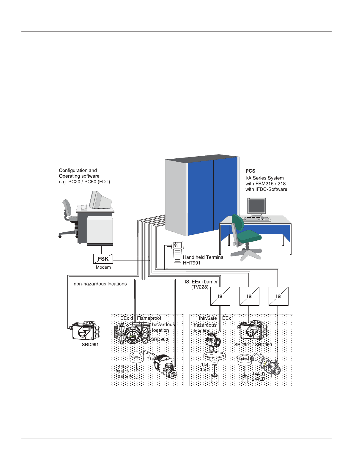
HART Communication . . . . . . . . . . . . . . . . . . . . . . . . . . . . . . . . . . . . . . . . . . . . . . . . . . . . . . . . . . . . . . 74
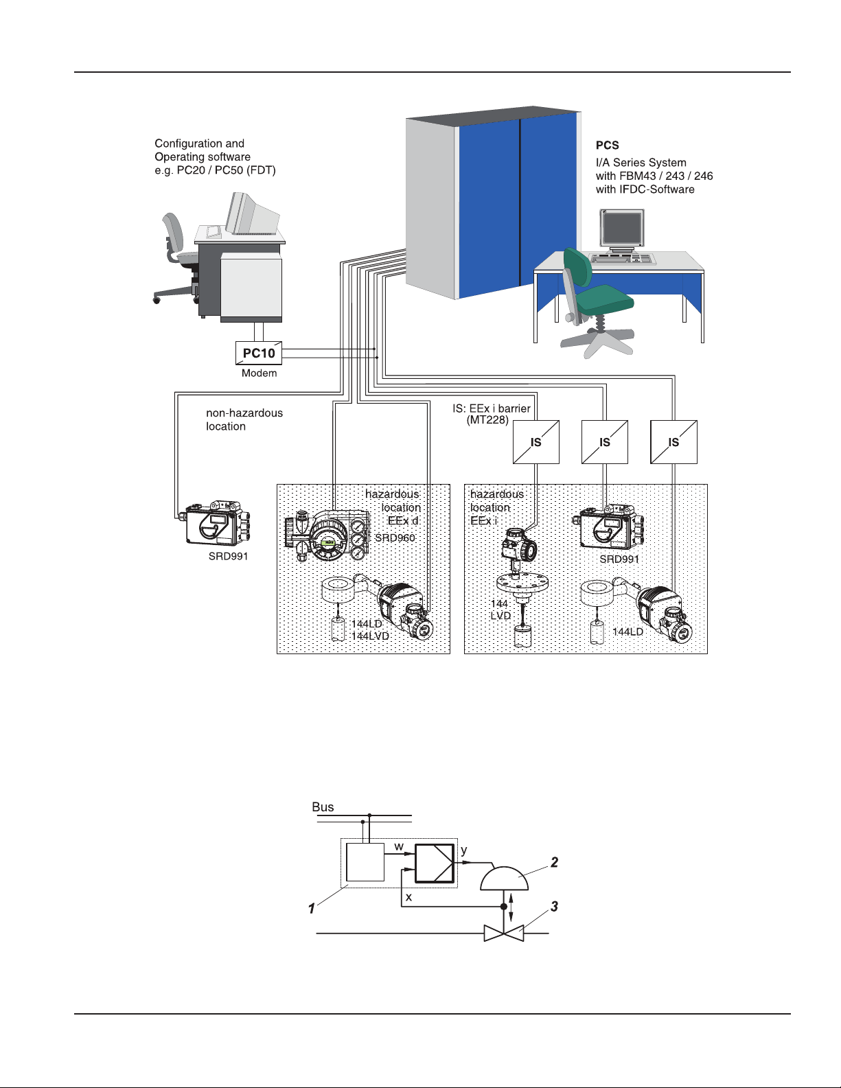
FoxCom Communication. . . . . . . . . . . . . . . . . . . . . . . . . . . . . . . . . . . . . . . . . . . . . . . . . . . . . . . . . . . . . 75
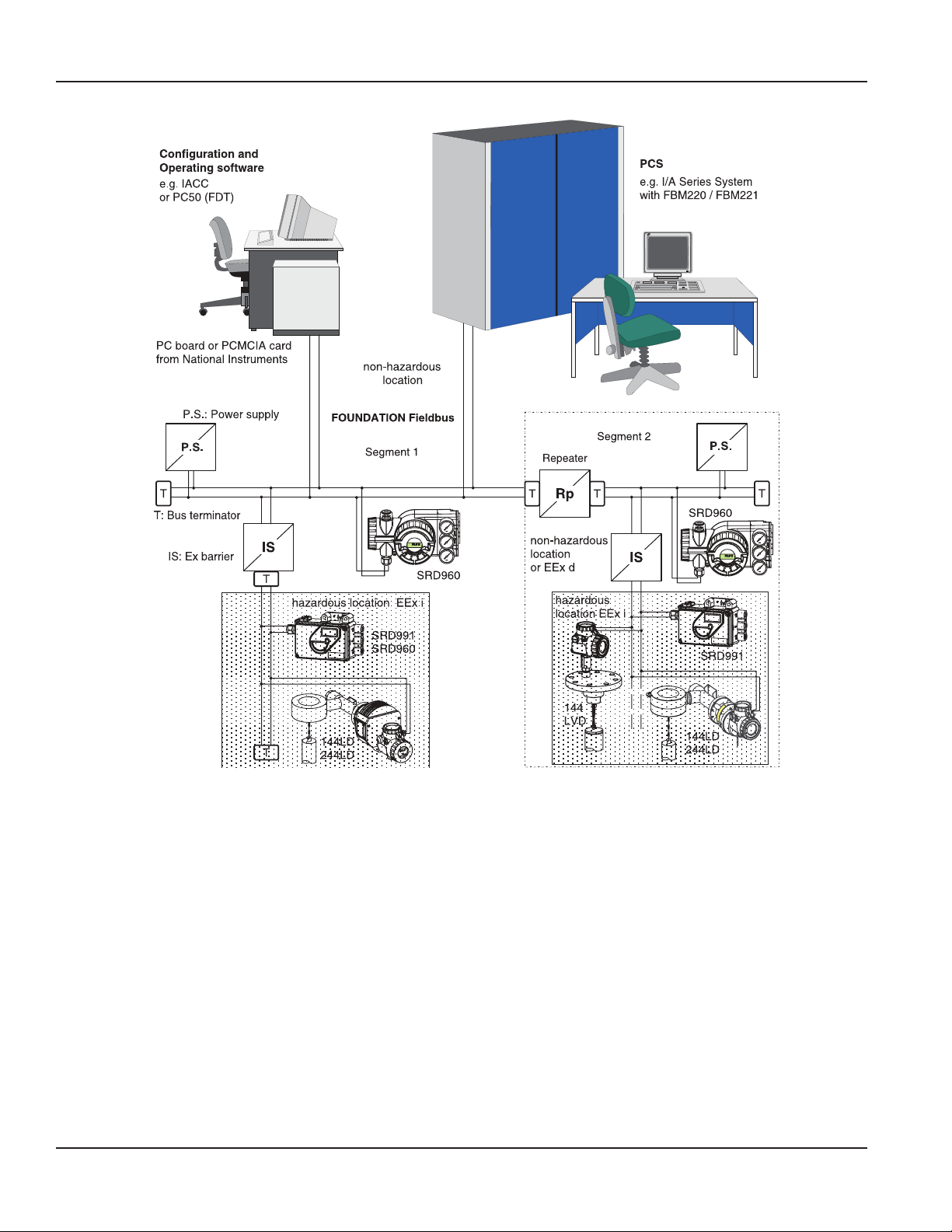
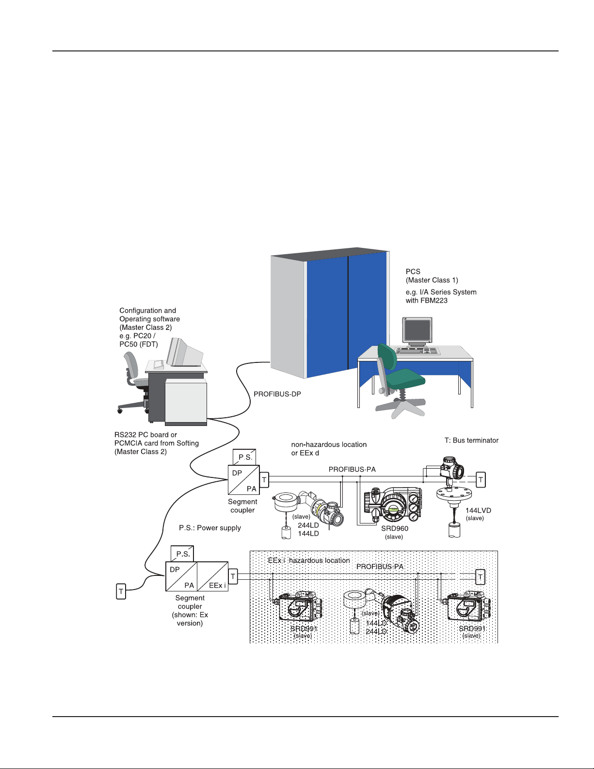
With Communication PROFIBUS-PA . . . . . . . . . . . . . . . . . . . . . . . . . . . . . . . . . . . . . . . . . . . . . . . . . . . . . . 75
With Communication FOUNDATION Fieldbus. . . . . . . . . . . . . . . . . . . . . . . . . . . . . . . . . . . . . . . . . . . . . . . . 76
System Conguration. . . . . . . . . . . . . . . . . . . . . . . . . . . . . . . . . . . . . . . . . . . . . . . . . . . . . . . . . . . . . . . 77
Dimensions . . . . . . . . . . . . . . . . . . . . . . . . . . . . . . . . . . . . . . . . . . . . . . . . . . . . . . . . . . . . . . . . . . . . . . . . 80
Dimensions INOX SRD991 in Stainless Steel Housing . . . . . . . . . . . . . . . . . . . . . . . . . . . . . . . . . . . . . . . . . . . 81
Page v August 2014 POS-UM-00010-EN-03
Page 6

Valve Positioners, RCV SRD991 Intelligent Positioner
Page vi August 2014POS-UM-00010-EN-03
Page 7

Device Features
The intelligent positioner SRD991 is designed to operate pneumatic valve actuators and can be operated from control
systems, controllers or PC-based configuration and operational tools, such as FDT/DTM Software. The positioner is available
with different communication protocols. The multi-lingual full text graphical LCD in connection with the three push-buttons
allows a comfortable and easy local configuration and operation as well as the display of valve specific data, and status and
diagnostic messages.
DEVICE FEATURES
• Autostart with self-calibration
• Self diagnostics, status and diagnostic messages
• Easy operation with three keys
• Multi-Lingual full text graphical LCD, or LEDs
• VALcare or Valve Monitor DTM for valve diagnostics and predictive maintenance
With Communication
• HART, FOUNDATION Fieldbus H1, PROFIBUS-PA, FoxCom
• Configuration by means of local keys, handheld terminal (HART), PC or I/A Series system or with a infrared interface by
means of IRCOM
Without Communication
• Input signal 4…20 mA
Common Features
• Stroke 8…260 mm (0.3…10.2 in.) with standard lever; larger stroke with special lever
• Angle range up to 95° (up to 300° on request)
• Supply air pressure up to 6 bar (90 psig), with spool valve up to 7 bar (105 psig)
• Single or double-acting
• Mounting on linear actuators according to NAMUR
◊ IEC 50534-6-1
◊ VDI/VDE 3847
• Mounting on rotary actuators according to VDI/VDE 3845 or IEC60534-6-2
• Protection class IP 66 and NEMA 4X
• Approved for SIL applications
• Explosion protection: Intrinsic safety according to ATEX and FM/CSA
Repair and maintenance operations must be carried out by qualified personnel!
Page 7 August 2014 POS-UM-00010-EN-03
Page 8
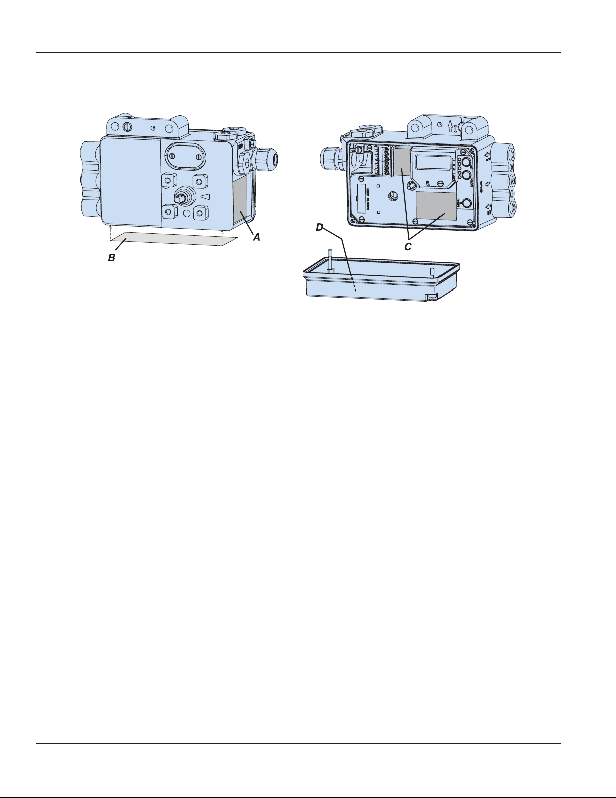
Labels
LABELS
A Nameplate
B Nameplate
C Warning labels, terminal wiring,key and
LED-designation
D Brief description inside cover
Page 8 August 2014POS-UM-00010-EN-03
Page 9

Unpacking & Inspection
UNPACKING & INSPECTION
Upon opening the shipping container, visually inspect the product and applicable accessories for any physical damage such
as scratches, loose or broken parts, or any other sign of damage that may have occurred during shipment.
OTE:N If damage is found, request an inspection by the carrier’s agent within 48 hours of delivery and file a claim with the
carrier. A claim for equipment damage in transit is the sole responsibility of the purchaser.
Installation and startup of instrument to be carried out only by qualified personnel, familiar with installation and start-up
procedures and operation of this product!
SAFETY INFORMATION
The installation of this product must comply with all applicable federal, state, and local rules, regulations, and codes.
Failure to read and follow these instructions can lead to misapplication or misuse of the product, resulting in personal injury
and damage to equipment.
Accident Prevention
The connected instrument contains mechanically moved parts, such as feedback levers, which could cause injuries. The
operators have to be instructed accordingly.
Electrical Safety
• This instrument satisfies the conditions for safety class III, overvoltage category I according to EN 61010-1 or IEC1010-1.
• Any work on electrical parts must be done by qualified personnel if any supply is connected to the instrument. The
instrument must be used for its designated purpose and connected in accordance with its connection diagram.
• Locally applicable installation regulations for electrical equipment must be observed, e.g. in the Federal Republic of
Germany DIN VDE 0100 resp. DIN VDE 0800.
• The instrument must be operated with safety extra low voltage SELV or SELV-E.
• Safety precautions taken in the instrument may be rendered ineffectual if the instrument is not operated in accordance
with the Master Instructions.
• Limitation of power supplies for fire protection must be observed due to EN 61010-1, appendix F or IEC 1010-1.
SUMMARY HART AND 4…20 MA WITHOUT COMMUNICATION
Mounting to Actuator (Valve)
The SRD991 can be mounted to linear or rotary actuators.
Connection and Startup
When connecting the supply air and applying a current source to the input terminals, pay attention to polarity. An initial
startup required no additional equipment.
Use the local push-buttons to change basic parameters such as type of actuator, side of installation, valve opens/closes with
increasing setpoint value, and characteristics curve of the valve (values set ex-factory: stroke actuator, mounting side: left,
valve opens with increasing setpoint value, linear characteristics curve).
Thereafter, an AUTOSTART can be performed during which the SRD991 determines independently the geometric data of the
actuator as well as control parameter, to ensure an optimized operation with the attached valve.
HART version:
The positioner can be operated either locally or via handheld terminal or PC (via modem).
Page 9 August 2014 POS-UM-00010-EN-03
Page 10
Summary – Hart and 4…20 mA without Communication
System Conguration
Version 4…20 mA without communication: Connection as traditional point-to-point connection according to the known
regulations of the measuring & control techniques.
HART version: When using ‘Communication’ (an AC signal which modulates on the 4-20 mA signal), make sure the
connected outputs, buffer amplifier and barriers are compatible with the frequency ranges used. In addition to the load,
the AC impedance requirements must be met. Therefore, it is recommended that only the specified amplifier, barrier and
configuration device be used.
To prevent crosstalk between lines and reduce disturbances through electromagnetic influences, use twisted-pair shielded
lines with a diameter of AWG 22…14 (0.3…2.5 mm2) and a maximum capacity of 100 pF/m.
The line capacities and connected devices may not exceed the maximum values listed for a particular HART protocol.
All components that are connected to the SRD in an explosion hazardous area require an Ex-Approval. The applicable limit
values must not be exceeded. Comply with the limit values when connecting additional capacitances, inductances, voltage or
current sources.
Page 10 August 2014POS-UM-00010-EN-03
Page 11

Summary – Foundation Fieldbus
SUMMARY FOUNDATION FIELDBUS
Mounting to Actuator (Valve)
The SRD991 can be mounted to linear or rotary actuators.
Connection and Startup
When connecting the supply air and applying a current source to the input terminals, pay attention to polarity. An initial
startup required no additional equipment.
Use the local push-buttons to change basic parameters such as type of actuator, side of installation, valve opens/closes with
increasing setpoint value, and characteristics curve of the valve (values set ex-factory: stroke actuator, mounting side: left,
valve opens with increasing setpoint value, linear characteristics curve).
Thereafter, an AUTOSTART can be performed during which the SRD991 determines independently the geometric data of the
actuator as well as control parameter, to ensure an optimized operation with the attached valve.
Bus Connection
The SRD 991 in the version FOUNDATION Fieldbus is bus compatible, which means that to a 2-core lead, the instruments have
to be attached in parallel according to IEC 1158-2. The lead serves as voltage feeder as well as for digital communication.
A FOUNDATION Fieldbus can consist of one or several segments, each with an individual length of up to 1900 meters. An
Ex-barrier should not be further than 100 meters from a bus terminal. To a segment up to 32 instruments can be attached.
A maximum of up to 240 instruments can be addressed (including repeater = connector of segments). To activate each
instrument individually, an individual address has to be entered.
From the factory, the address 29h (41) is always stored. This address can be changed automatically with the NI-Configurator.
System Integration
With the NI-Configurator changes in the configuration of the SRD991 can be carried out. The required files (*.FFO, *.SYM,
*.CFF) can be downloaded from the Internet by path
http://www.foxboro-eckardt.com/products/srd991_en.html.
Page 11 August 2014 POS-UM-00010-EN-03
Page 12
More informations about FOUNDATIONFieldbus seewww.fieldbus.org
Summary – Probus-PA
SUMMARY PROFIBUSPA
Mounting to Actuator (Valve)
The SRD991 can be mounted to linear or rotary actuators.
Connection and Startup
When connecting the supply air and applying a current source to the input terminals, pay attention to polarity. An initial
startup required no additional equipment.
Use the local push-buttons to change basic parameters such as type of actuator, side of installation, valve opens/closes with
increasing setpoint value, and characteristics curve of the valve (values set ex-factory: stroke actuator, mounting side: left,
valve opens with increasing setpoint value, linear characteristics curve).
Thereafter, an AUTOSTART can be performed during which the SRD991 determines independently the geometric data of the
actuator as well as control parameter, to ensure an optimized operation with the attached valve.
Page 12 August 2014POS-UM-00010-EN-03
Page 13
More informations about PROFIBUS see www.profibus.com
1)
Summary – Probus-PA
Bus Connection
The SRD 991 PROFIBUS-PA version is bus compatible, which means that to a 2-core lead the instruments have to be attached
in parallel according to IEC 1158-2. The lead serves as voltage feeder as well as for digital communication. To activate each
instrument individually, an individual address has to be entered.
From the factory the address 126 is always stored 1); Since this address cannot be used during operation, a new address has to
be entered in every instrument. This can be done via the local keys, with the FDT/DTM software or a commercial configurator.
To a PROFIBUS-PA-segment with a length of up to 1900 meters, up to 32 instruments can be attached. A maximum of up to
126 instruments can be addressed with PROFIBUS.
System Integration
During operation the SRD991 will communicate with a PROFIBUS master class 1. The required GSD-file (“instrument-specific
dates”) can be downloaded from the Internet by path
http://www.foxboro-eckardt.com/products/srd991_en.html.
as per profile 3.0
Page 13 August 2014 POS-UM-00010-EN-03
Page 14

Summary – FoxCom (Digital)
SUMMARY FOXCOM DIGITAL
Mounting to Actuator (Valve)
The SRD991 can be mounted to linear or rotary actuators.
Connection and Startup
When connecting the supply air and applying a current source to the input terminals, pay attention to polarity. An initial
startup required no additional equipment.
Use the local push-buttons to change basic parameters such as type of actuator, side of installation, valve opens/closes with
increasing setpoint value, and characteristics curve of the valve (values set ex-factory: stroke actuator, mounting side: left,
valve opens with increasing setpoint value, linear characteristics curve).
Thereafter, an AUTOSTART can be performed during which the SRD991 determines independently the geometric data of the
actuator as well as control parameter, to ensure an optimized operation with the attached valve.
FoxCom version:
The positioner can be operated either locally, via PC, or via I/A Series System (FoxCom).
System conguration
When using ‘Communication’ (a digital signal with constant amplitude), make sure the connected outputs, buffer amplifier
and barriers are compatible with the frequency ranges used. In addition to the load, the AC impedance requirements must be
met. Therefore, use only the specified amplifier, barrier and configuration device.
To prevent crosstalk between lines and reduce disturbances through electromagnetic influences, use twisted-pair shielded
lines with a diameter of AWG 22–14 (0.3…2.5 mm2) and a maximum capacity of 100 pF/m.
The line capacities and connected devices may not exceed the maximum values listed for a particular FoxCom protocol.
All components connected to the SRD in an explosion hazardous area require an Ex-Approval. The applicable limit values
must not be exceeded. Comply with the limit values when connecting additional capacitances, inductances, voltages
and currents.
Page 14 August 2014POS-UM-00010-EN-03
Page 15
Method of Operation
METHOD OF OPERATION
General
The intelligent positioner SRD991 1 and the pneumatic actuator 2 form a control loop with the setpoint value w (from master
controller or control system), the output pressure y and the position x of the actuator on valve 3.
Figure 1: Fieldbus version
For the supply air, use a filter regulator.
Page 15 August 2014 POS-UM-00010-EN-03
Page 16
sAir supply 1.4... 6 bar (20... 90 psig)
Method of Operation
The positioner can be attached to both linear and rotary actuators.
Actuators with spring force are controlled by a single acting positioner. Actuators without spring force are controlled by a
double acting positioner.
HART or FoxCom version:
The positioner can be operated locally by means of local keys or a handheld terminal, or remotely via PC-based configuration
or a corresponding control system.
PROFIBUS-PA or FOUNDATION Fieldbus version:
The positioner can be operated locally by means of local keys, remotely via a corresponding control system, or can be
operated via PC-based configuration and operating tools.
Block Diagram
Input (w) each
acc.to version:
Analog operation
•
4...20mA
(+FSK)
• Digital operation
FSK
13...36 VDC
• Bus input
y
1
y
2
Output
pressure
to actuator
xPosition
of actuator
Operation
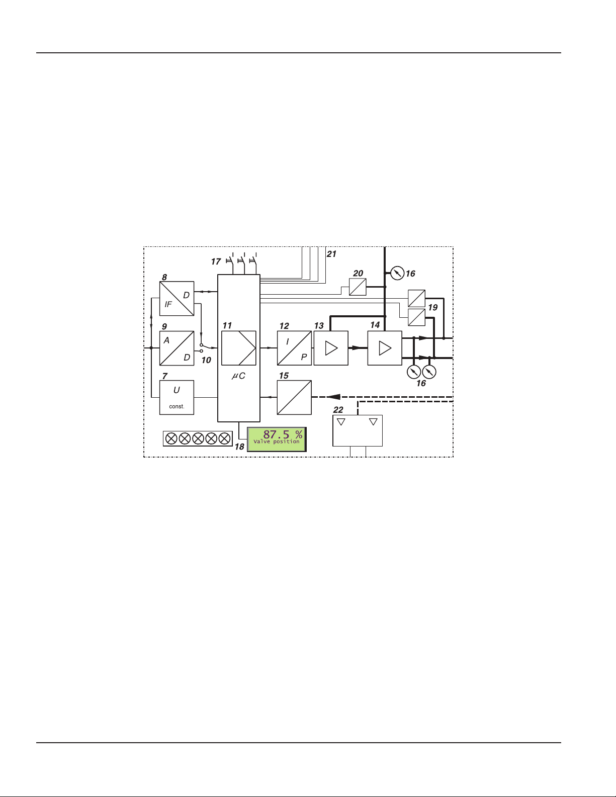
With the intelligent positioner with input signal 4-20 mA or superimposed HART signal, the supply takes place via the power
signal adjacent to the input.
By means of voltage converter 7, derivation of the internal supply of the electronics takes place. The power value is measured,
in A/D transformer 9 converted, and directed via switch 10 to digital controller 11.
With PROFIBUS-PA or FOUNDATION Fieldbus, the SRD is powered by means of the bus cable. The positioner is operated
from a control system by sending a setpoint (setpoint value) to the positioner. The digital signal is directed via the interface
component 8 to the digital controller 11. By means of the voltage converter 7 the internal supply of the electronics is
established, fed via the bus cable.
With FoxCom digital operation, a DC voltage is provided at input w. On this voltage an FSK signal is modulated. The
modulation contains information, such as setpoint value, sent digitally to the control unit 11 across the FSK unit 8.
The output of controller 11 drives the electro-pneumatic converter (IP-module) 12, controlling a pre-amplifier 13, the
single acting (or double acting) pneumatic power amplifier 14. The output of the amplifier 14 is the output pressure y to
the actuator.
The pneumatic amplifiers are supplied with supply air 1.4…6 bar (20…90 psig).
The position x of the actuator is sent to the control unit 11 by the position sensor (conductive plastic potentiometer) 15.
Optional gauges 16 , pressure sensors 19 , 20 , inputs / outputs 21 (two binary outputs; a 4…20 mA output and alarm;
control inputs for ‘Open/Close’ and ‘Hold last value’) enable additional diagnostic indications and possible intervention. The
mechanical limit switch 22 (optional) enables independent alarm signals.
Page 16 August 2014POS-UM-00010-EN-03
Page 17

Operating Modes
Adjusting and startup of the positioner, as well as the demand for internal information, can be made using the local keys 17
with indication given by LCD, 18 or LEDs.
OPERATING MODES
Operation of the positioner is divided into individual operating modes. Operating modes may change depending on, for
example, key commands or internal calculations. The different operating modes are described in abbreviated form below.
Initialize
Upon powerup or reset (pressing the 3 keys simultaneously), several self-tests are conducted. Individual steps in the self-test
process are indicated by the LCD or green LEDs.
If no error occurs, the device moves to OUT OF SERVICE, if it is still in a delivery condition; AUTOSTART has to be performed. If
AUTOSTART was done already, the device will go to IN OPERATION.
If faults are detected, the code of the faulty self-test will remain. If error occurs again after reset, the device is probably
defective and should be sent in for repair.
Device Fault
In the event that the LCD shows a message (or red LED lights up constantly and all green LEDs are off), a device fault is
signaled. These faults are detected during cyclical self-test.
The device can no longer be operated. This could be caused by a jammed menu key or defective program memory.
If a device error occurs repeatedly, the device should be sent in for repair.
In Operation
After performing an AUTOSTART, the device moves to IN OPERATION and will always, even after restarting or resetting, move
back to the safety position (de-energized valve position) or FAILSAFE. If setpoint values are fed via communication, the SRD
will go to IN OPERATION.
Failsafe
With FF H1 and Profibus PA Communication
Positioner carries out actions as configured in menu “failure handling”. Additionally, the cyclical self-diagnosis takes place.
If the instrument is IN OPERATION, but no setpoint values arrive via communication, the SRD will go to FAILSAFE mode, after a
defined time period; either with
• maintaining last value
• output pressureless, or
• with predetermined position.
As soon as setpoint values arrive via communication again, the instrument is immediately back IN OPERATION.
Out of Service
The SRD991 as delivered is configured to remain OUT OF SERVICE after powerup until moving to IN OPERATION via the
manually initiated function AUTOSTART.
In the device state OUT OF SERVICE, the menu entering mode remains active at all times. If a device has been IN OPERATION
already and is removed from an actuator and mounted to another, it is recommended to take the device out of operation via
RESET CONFIG (Menu 9.1) prior to disconnecting the device from the first actuator.
This enables the next actuator to be started in the delivered condition (see “Startup”).
Calibrate
During an AUTOSTART function the device is in condition CALIBRATION. The actuator is moved up- and downward several
times, and the device could be busy for a few minutes. Subsequently, the device moves to IN OPERATION.
Page 17 August 2014 POS-UM-00010-EN-03
Page 18

Operating Modes
Message
The SRD991 continuously supervises important device functions. In the event that limit values are exceeded or operational
problems occur, messages are signaled via the LCD or the special LED blinking mode.
The message with the highest priority will be indicated first. With key DOWN additional messages can be called up, with
key UP the measuring values can be retrieved. It is possible at all times to reach the menu by pressing the menu keys to
possibly eliminate the problem by performing suitable menu functions. Further references may be found in chapter “Troubleshooting”.
Simulate (Foundation Fieldbus Version Only)
During function IN OPERATION, the valve position queried via the communication, can be simulated with a value that has
been entered via communication into the instrument during position SIMULATION. Thereby the positioner continues with
normal operation and regulates to the ”accurate” set value.
For the SRD, this function has to be additionally released or blocked via menu 10.
LCD description, definition of the LEDs and possible operator interventions are described in “Startup” on page 39.
Page 18 August 2014POS-UM-00010-EN-03
Page 19
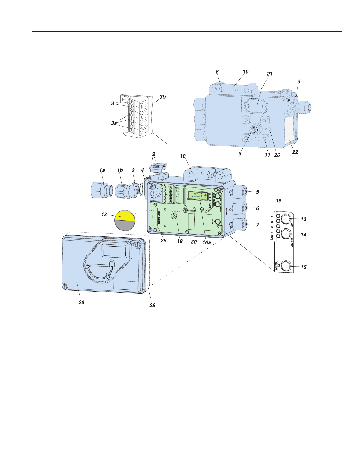
FUNCTIONAL DESIGNATIONS
10
11
12
13
14
15
4) Depending on theversion,the device is equipped with or withoutLEDs
Functional Designations
1a Adapter, eg. 1/2”-14 NPT
1b Cable gland
2 Plug, interchangeable withPos.1
3
Screw terminals1)(11 / 12) for input (w)or
for bus connectionIEC 1158-2
3)
3a Screw terminals1)for additional inputs/outputs
3b Test socketsØ2mm, integrated in terminalblock
4 Ground connection
5 Female threadG)1/4 -18 NPT or outputI(y1)
6 Female threadG)1/4 -18 NPT for air supply (s)
7 Female thread
G)
1/4 -18 NPT or outputII (y2)
8 Direct attachment holefor outputI(y1)
9 Feedback shaft
Connection manifold forattachment to stroke actuators
(not withVDI/VDE 3847 version)
Connection base forattachment to rotary actuators
Travel indicator
Key UP
Key DOWN
Key M (Menu)
16 Status display(1red LED, 4 green LEDs)
16a LCD withtruetext in 3different languages
19 Fixing shaftfor limit switch
20 Coverwith window to 12
Air vent, dust and water protected
21
22 Data label
23 Tipjacks
2)
Ø2mm forcurrent measurement
24 Switch2)for currentmeasurement
25 Tipjacks2)Ø2mm forcommunication
26 Arrow is perpendicular to shaft 9 at angle 0 degree
27 Ball valvefor protection class NEMA 4X
28 High cover withbuilt-in limit switch
29 Plug for service connector
3)
30 IrCom interface
G) With marked letter "G"inthe housing the pneumatic connecting threads
arecut as G1/4 instead of 1/4-18 NPT
1) Alternatively Cageclamps(WAGO) instead of screwterminals
2) Only with FoxCom version
3) Not with FoxCom version
Page 19 August 2014 POS-UM-00010-EN-03
Page 20
T
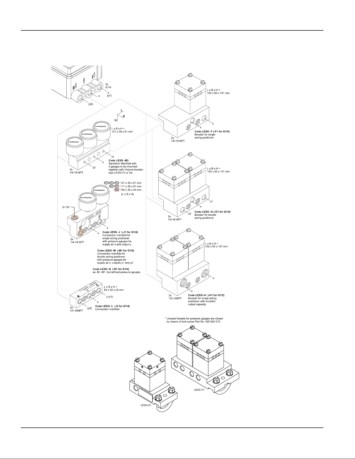
LEXG-F1:
LEXG-G1:
LEXG-H1:
Alternative:
Amplifier,
(Connection
LEXG-X1:
LEXG-Y1:
LEXG-Z1:
When mounting, check theproper seating of theO-rings
Functional Designations
Pneumatic Accessories
andbolt on theaccessorieswiththe twoM8 bolts. Unused
outputs are closed by meansof plastic plugs.
ypes withG-threads instead of standard NPT-threads:
As LEXG-F, however withthread G1/4
As LEXG-G, however withthread G1/4
As LEXG-H, however withthread G1/2
independent of positioner:
from positioner to amplifier with tubes)
As LEXG-F1, however externally mounted
As LEXG-G1, however externally mounted
As LEXG-H1, however externallymounted
Page 20 August 2014POS-UM-00010-EN-03
Page 21
Mounting to Actuators
MOUNTING TO ACTUATORS
NAMUR Mounting Linear Actuator, Left Side
Applicable to actuators with cast yoke or pillar yoke according to NAMUR (DIN IEC 534-6).
Mounting the positioner with pneumatic connections on the left side and electrical connections on the lower right side.
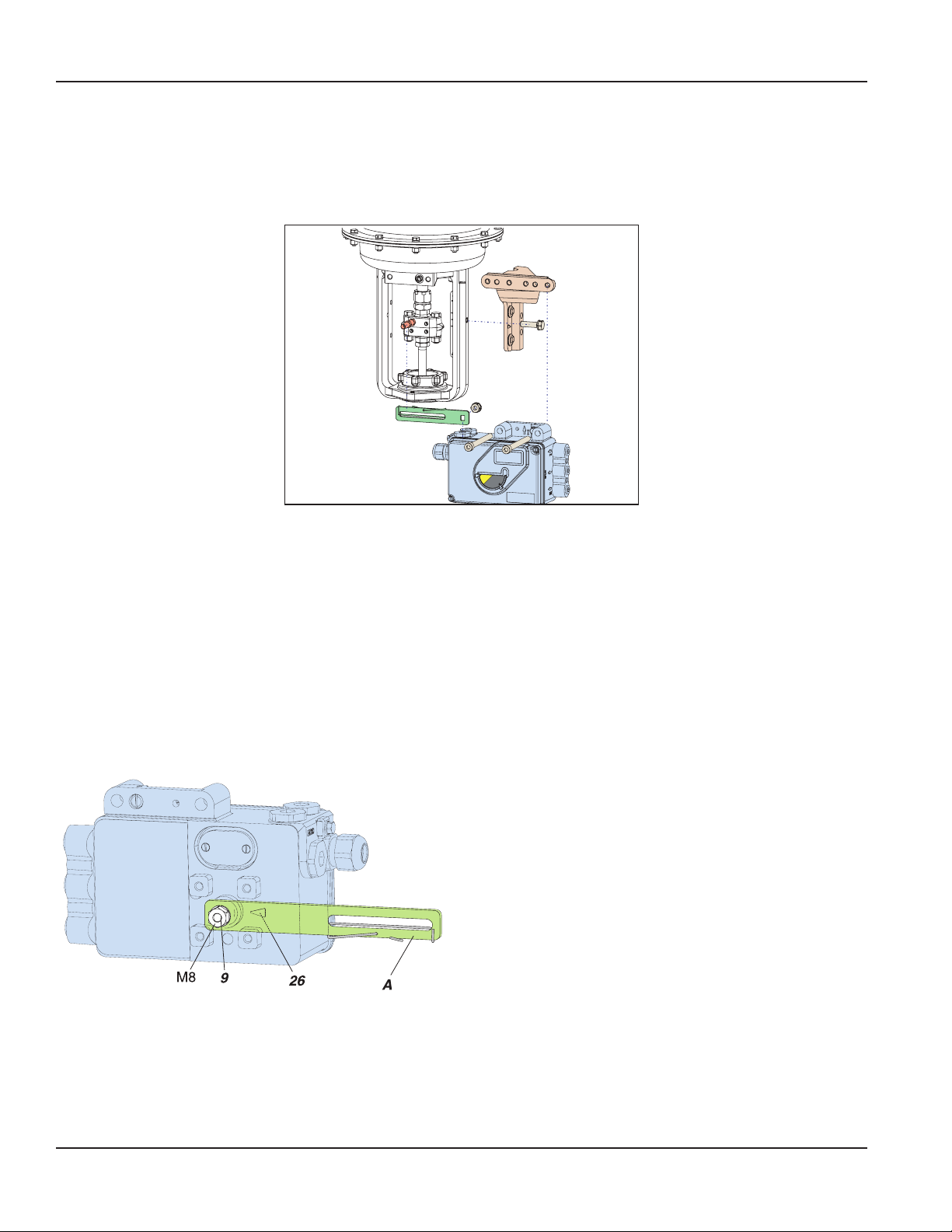
Figure 2: NAMUR mounting, left side
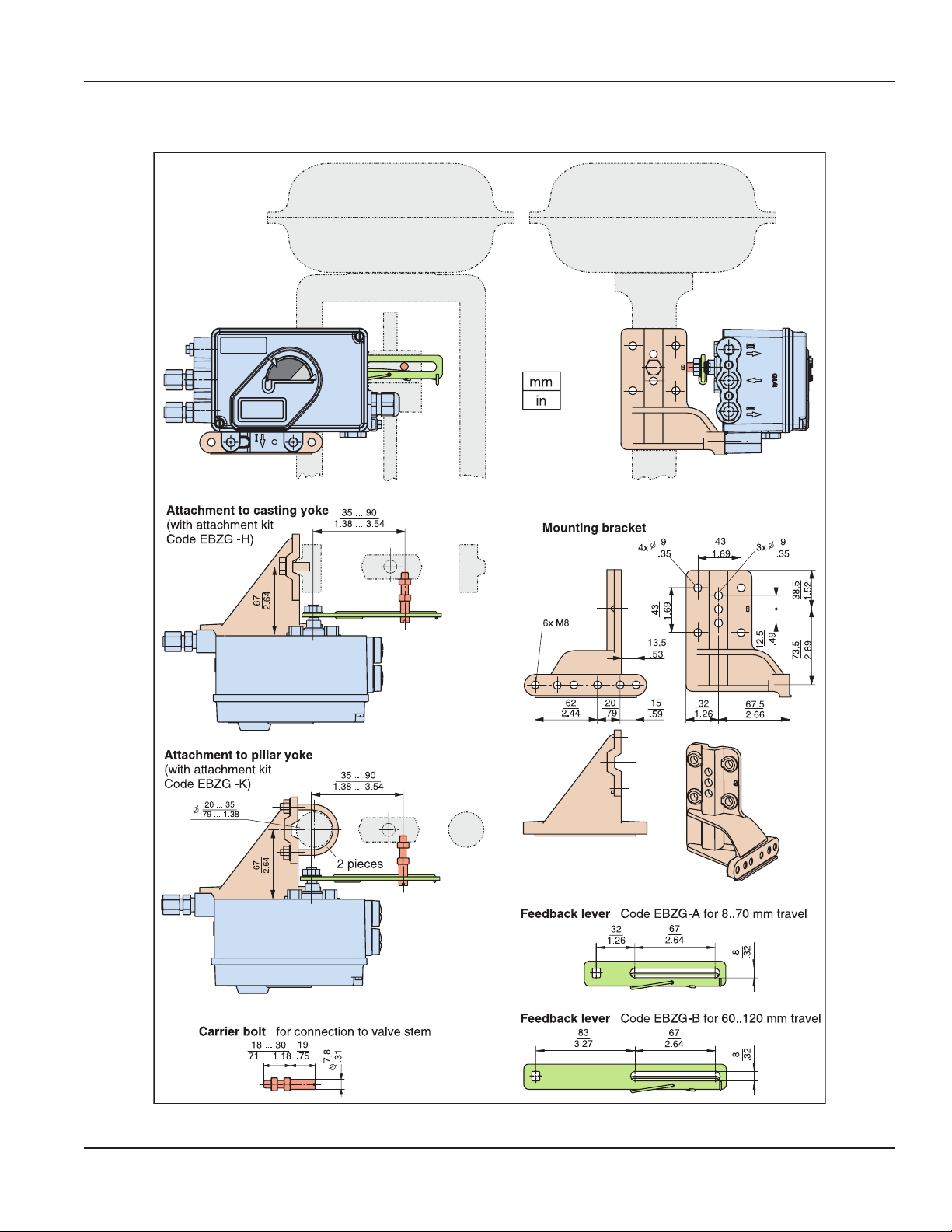
Attachment of the positioner to the actuator is made to the left using the mounting bracket and feedback lever for a NAMUR
mount. Use:
attachment kit EBZG -H for a cast yoke, or
attachment kit EBZG -K for a pillar yoke.
The side outputs I (or I and II) are used. The rear output I is closed by means of a lock screw 522 588 013.
Pneumatic connections: Do not use Teflon tape for sealant. The fine fibers could disturb the function of the SRD. Apply only
Loctite® #243 sealant to the male thread.
Screw-type glands for electrical connections are positioned on the lower or right side. Any unused threaded holes are closed
by plugs.
If housing cover has an air vent, this air vent must facedown when mounted.
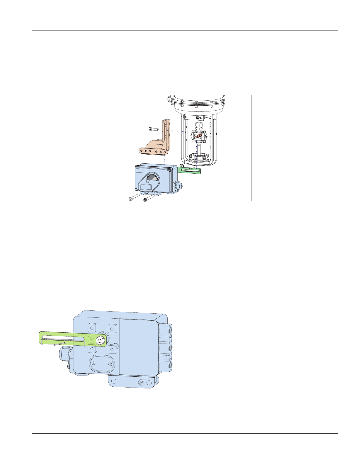
Preparing the Positioner
Rotate the shaft stub of shaft 9 so that the flat on the shaft stub
is perpendicular to the arrow 26 on the housing at mid travel
range (detail see “Mounting Dimensions for Direct Mounting”).
Fasten the feedback lever A to the shaft by means of spring
washer and nut M8.
Figure 3: Feedback lever
Page 21 August 2014 POS-UM-00010-EN-03
Page 22
Mounting to Actuators
Preparing the Actuator
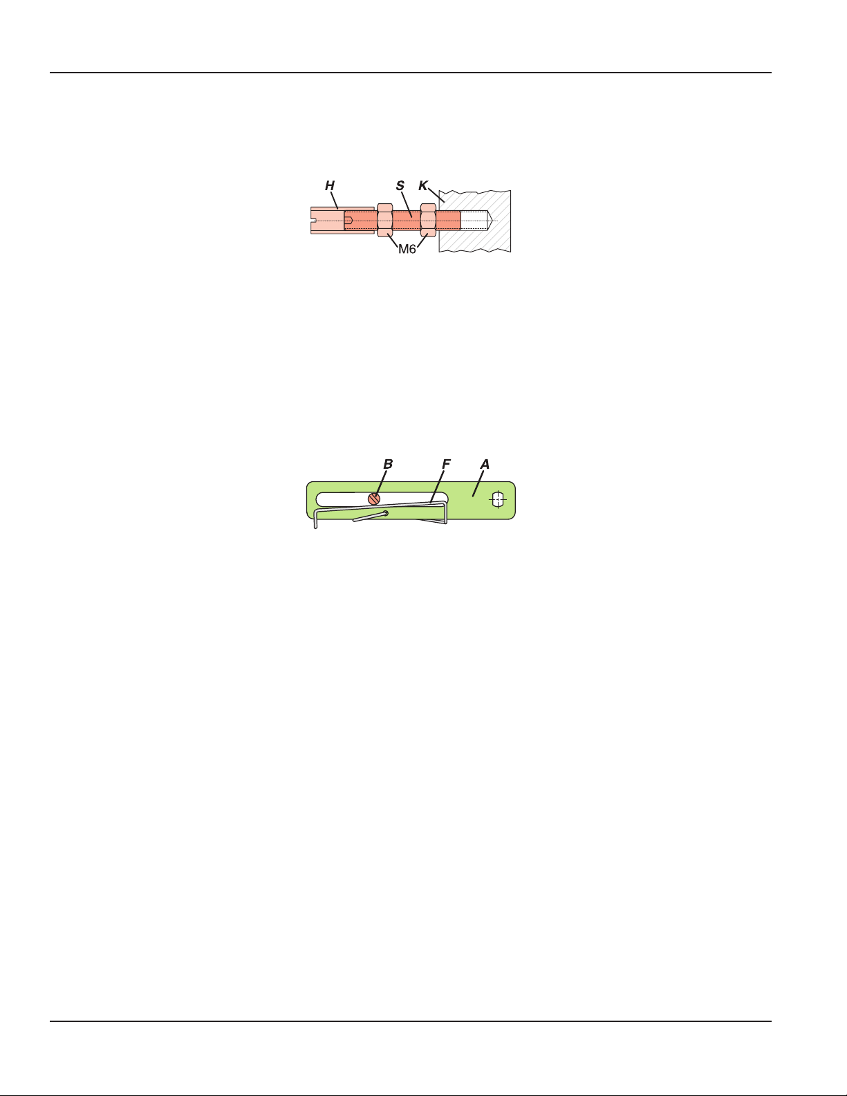
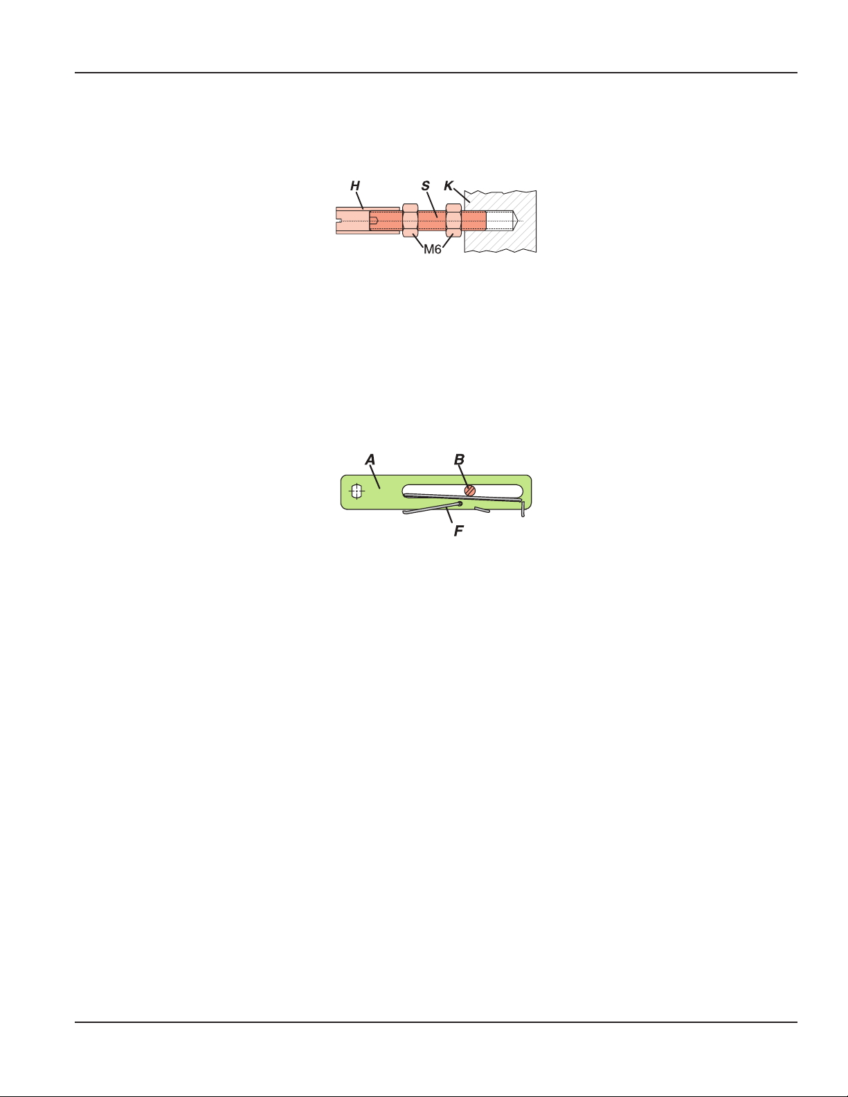
Screw the carrier bolt to the stem connector and lock it by means of a counter nut.
A carrier bolt with an adjustable length is used to be able to screw on various coupling pieces.
Figure 4: Carrier bolt
It consists of a stud S, which is screwed into the coupling piece K (with 3 mm Allen key) and locked with a lock nut M6. The
threaded sleeve H is screwed onto it and locked with a lock nut M6. Make sure that the bolt is adjusted to the right length!
Fasten the mounting bracket to the left side of the yoke. For a cast yoke use a screw M8 x 30, for a pillar yoke use two U-bolts
and four nuts.
Mounting of the Positioner
Fasten the positioner to the mounting bracket using two spring washers and two screws M8 x 80.
Note, the carrier bolt B is in the slot of the feedback lever A and the compensating spring F touches the carrier bolt.
Figure 5: Feedback lever
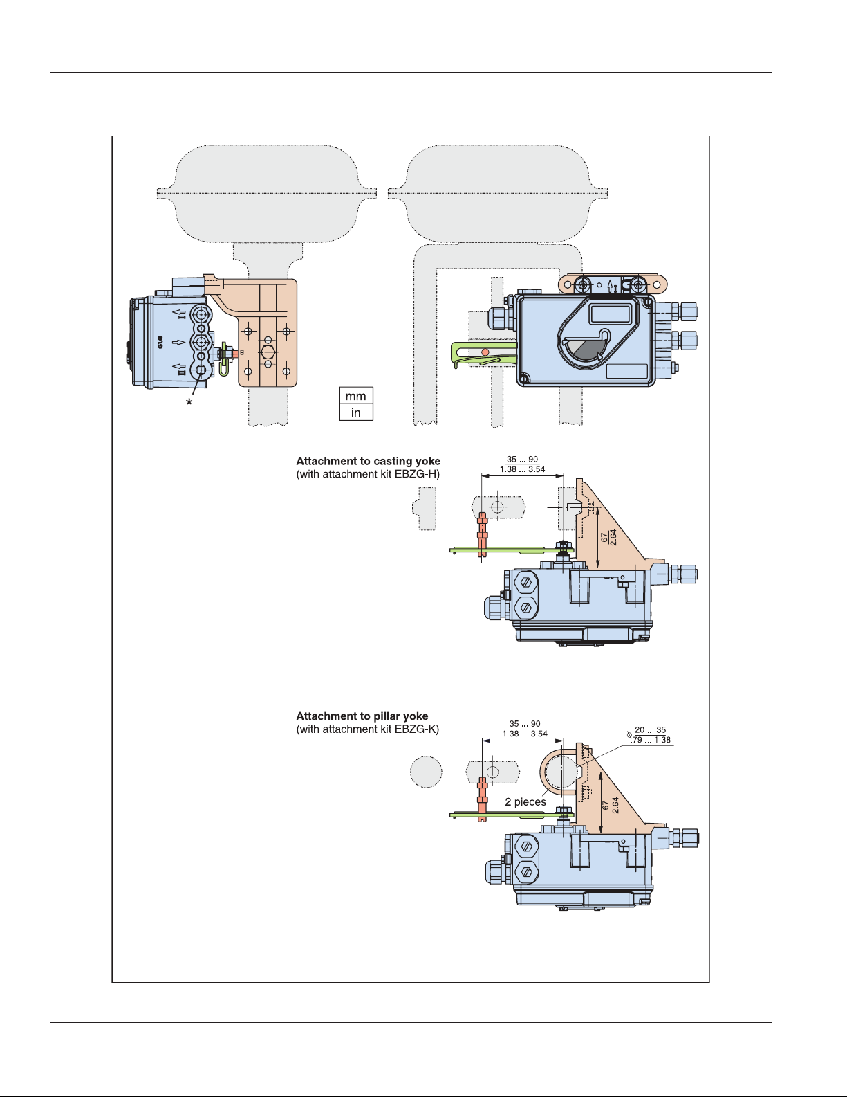
For optimum use of the positioner operating range, it is recommended that the arrangement is adjusted according to the
following procedure before fixing. At an actuator position in the middle of travel range, the feedback lever position should be
perpendicular to the actuator stem and the angle range should be between −10…10° and −45…45°.
Fasten the positioner to the mounting bracket so that a suitable angle range is selected.
It is recommended that the pneumatic and electrical connections are made after adjusting the position.
Page 22 August 2014POS-UM-00010-EN-03
Page 23
NAMUR Mounting Dimensions – Left Side
LCD orientation canbe
changed by means of local
push buttons under Menu
9.9.2to„flipped“,to ensure
acorrect orientation of the
display.
Mounting to Actuators
Page 23 August 2014 POS-UM-00010-EN-03
Page 24
Mounting to Actuators
NAMUR Mounting Linear Actuator, Right Side
Right-side mounting is done if left-side mounting is not possible for structural reasons.
Applicable to actuators with cast yoke or pillar yoke according to NAMUR (DIN IEC 534-6).
Mounting the positioner with pneumatic connections on the right side and electrical connections on the left side.
Figure 6: NAMUR mounting, right side
Attachment of the positioner to the actuator is made to the right using the mounting bracket and feedback lever for a
NAMUR mount. Use:
attachment kit EBZG -H for a cast yoke, or
attachment kit EBZG -K for a pillar yoke.
The side outputs I (or I and II) are used. The rear output I is closed by means of a lock screw 522 588 013.
Pneumatic connections: Do not use Teflon tape for sealant. The fine fibres could disturb the function of the SRD. Apply only
Loctite® #243 sealant to the male thread.
Screw-type glands for electrical connections are positioned on the left side. Any unused threaded holes are closed by plugs.
If housing cover has an air vent, this air vent must facedown when mounted.
Preparing the Positioner
Rotate the shaft stub of shaft 9 so that the flat on the shaft stub
is perpendicular to the arrow 26 on the housing at mid travel
range (detail see “NAMUR Mounting Dimensions – Right Side”).
Fasten the feedback lever A to the shaft by means of spring
washer and nut M8.
Figure 7: Feedback lever
Page 24 August 2014POS-UM-00010-EN-03
Page 25
Mounting to Actuators
Preparing the Actuator
Screw the carrier bolt to the stem connector and lock it by means of a counter nut.
A carrier bolt with an adjustable length is used to be able to screw on various coupling pieces.
Figure 8: Carrier bolt
It consists of a stud S, which is screwed into the coupling piece K (with 3 mm Allen key) and locked with a lock nut M6. The
threaded sleeve H is screwed onto it and locked with a lock nut M6. Make sure that the bolt is adjusted to the right length!
Fasten the mounting bracket to the left side of the yoke. For a cast yoke use a screw M8 x 30, for a pillar yoke use two U-bolts
and four nuts.
Mounting the Positioner
Fasten the positioner to the mounting bracket using two spring washers and two screws M8 x 80.
Note, the carrier bolt B is in the slot of the feedback lever A and the compensating spring F touches the carrier bolt.
Figure 9: Feedback lever
For optimum use of the positioner operating range, it is recommended the arrangement be adjusted according to the
following procedure before fixing. At an actuator position in the middle of travel range, the feedback lever position should be
perpendicular to the actuator stem and the angle range should be between −10…10° and −45…45°.
Fasten the positioner to the mounting bracket so that a suitable angle range is selected.
It is recommended that the pneumatic and electrical connections are made after adjusting the position.
Page 25 August 2014 POS-UM-00010-EN-03
Page 26
Mounting to Actuators
NAMUR Mounting Dimensions – Right Side
Mounting bracket,feedback lever and
carrier bolt
Page 26 August 2014POS-UM-00010-EN-03
Page 27

Mounting to Actuators
Linear Actuator, Direct Mounting
Actuators with appropriately prepared yoke (PA200, PA350) enable mounting of the SRD991 directly to the actuator yoke.
Figure 10: Direct mounting
Bolt the positioner directly to the actuator yoke using the feedback lever for a direct mount (with attachment kit EBZG -D).
The rear output I and the side outputs I and II are used as follows:
• Actuator single acting, spring force closes:
The rear output I is used (remove lock screw in hole D ).
The side output I is closed by means of a lock screw.
• Actuator single acting, spring force opens:
The side output I is used.
The rear output I is closed by means of a lock screw.
• Actuator double acting:
The rear output I and the side output II is used.
The side output I is closed by means of a lock screw.
Pneumatic connections: Do not use Teflon tape for sealant. The fine fibers could disturb the function of the SRD. Apply only
Loctite® #243 sealant to the male thread.
Screw-type glands for electrical connections are positioned on the side. Any idle female threads are closed by means of plugs.
If housing cover has an air vent, this air vent must facedown when mounted.
Page 27 August 2014 POS-UM-00010-EN-03
Page 28

M6
B
R
Mounting to Actuators
Preparing the Positioner
Figure 11: Feedback lever
Preparing the Actuator
Rotate the shaft stub of shaft 9 so that the flat on the shaft stub
is perpendicular to the arrow 26 on the housing at mid travel
range (detail see “Mounting Dimensions for Direct Mounting”).
Fasten the feedback lever A to the shaft by means of spring
washer and nut M8.
Screw in the carrier bolt B on the coupling piece K on the drive
spindle S at the lower left and lock it by means of a nut M6.
Figure 12: Carrier bolt
Mounting the Positioner
Figure 13: Feedback lever
KS
Fasten the positioner to the upper part of the yoke using 2
spring washers and 2 screws M8 x 80, as shown above. The rear
output I of positioner has contact to the air duct R in the yoke.
Note the correct position of the O-ring on the yoke for the rear
connection I!
Note, the carrier bolt B is in the slot of the feedback lever A and
the compensating spring F touches the carrier bolt.
Page 28 August 2014POS-UM-00010-EN-03
Page 29

Mounting Dimensions for Direct Mounting
Mounting to Actuators
Page 29 August 2014 POS-UM-00010-EN-03
Page 30

Mounting to Actuators
Mounting to Rotary Actuators
Applicable to rotary actuators that meet the VDI/VDE 3845 standard for mounting. Installation position of positioner: Mount
the positioner so that the pneumatic connections are in the same direction as the longitudinal drive axis of the actuator as
shown in the photograph below.
Figure 14: Mounting to rotary actuator
The feedback shaft 9 of the SRD has no mechanical stop, therefore may spin 360°. The permissible rotation angle
range is between 50…–50° around the arrow at the housing concerning the flat area of the feedback shaft (also see
“Mounting Dimensions for Direct Mounting” bottom). Since a rotary actuator has a rotary angle of about 90°, the mounting as
described in the following must be carried out very precisely.
Attachment of the positioner to the actuator is made by using the rotary adaptor kit EBZG -R.
Either the side outputs I (or I and II) are used and the rear output I is closed by means of the lock screw 522 588 013.
Pneumatic connections: Do not use Teflon tape for sealant. The fine fibers could disturb the function of the SRD. Apply only
Loctite® #243 sealant to the male thread.
Screw-type glands for electrical connections are used as needed. Any unused threaded holes are closed by plugs.
PREVENT ACCUMULATION OF WATER IN THE INSTRUMENT IN THIS MOUNTING POSITION BY SEALING CABLE ENTRY
AGAINST WATER. PROVIDE A CONTINUOUS SUPPLY OF DRY INSTRUMENT AIR.
Preparing the Positioner
Valve must be in failsafe position and the direction of rotation of the actuator drive shaft must be known. These items are
extremely important for proper functioning. These items can be checked as follows in case they are not clear:
• In the single-acting actuator the force of the installed spring closes. The pressure-less actuator is in failsafe position.
Through manually feeding compressed air it can be seen whether the actuator drive shaft rotates to the left or to the right.
• In the double-acting actuator (without spring reset) both air chambers are basically equal. Failsafe position can be either
“open” or “close”. Therefore, indication of the failsafe position has to be determined by engineering. Then the direction of
rotation may be determined by manual feeding of compressed air.
Bolt 2 is screwed into actuator drive shaft 1 for subsequent centering of the rotary adaptor 3. The attachment console is
mounted to the stroke actuator (see illustration).
Page 30 August 2014POS-UM-00010-EN-03
Page 31

Figure 15: Attachment diagram for bracket
Mounting to Actuators
Figure 16: Rotary adaptor
Preparing the Actuator
Prepare the rotary adapter:
• For attachment to a counter-clockwise or left turning actuator, secure the stud screw 4 in the threaded hole “L” of the
rotary adaptor; hole “R” remains open.
• For attachment to a clockwise or right turning actuator secure the stud screw 4 in the threaded hole “R” of the rotary
adaptor; hole “L” remains open. Stud screw should always be tightened into the flat on the on the feedback shaft 9.
Place the rotary adaptor 3 with two washers 5 on the feedback shaft 9 of the positioner against the stop.
OTE:N When the product temperature rises, the drive shaft 1 becomes longer. Therefore, mount the rotary adaptor 3 with
approximately 1 mm (0.04 in.) of clearance between the drive shaft 1 and the rotary adaptor 3. Add washers 5 on the
feedback shaft stub 9 before attaching the rotary adaptor. Two washers should result in a clearance of 1 mm.
Screw and tighten the bolt in the coupling against the flat part of the feedback shaft (do not screw against thread!).
Turn the feedback shaft so that the arrow of the coupling points to the arrow of the SRD housing. Beginning and end
positions of the actuator drive shaft 1 and feedback shaft 9 are marked by arrows for the respective direction of rotation.
The feedback shaft is now in the normal position corresponding to the failsafe position of the actuator.
Page 31 August 2014 POS-UM-00010-EN-03
Page 32

Mounting to Actuators
Mounting the Positioner
SRD and actuator are in failsafe position.
Attach the SRD on the console in such a way that the catch of coupling 3 is guided into the groove of shaft 1. Use bolt 2 to
center and align the positioner to the actuator. Be careful not to shift shafts 1 and 9 and that both shafts are exactly flush.
Fasten the positioner to the bracket by means of 4 lock washers and 4 screws M6 x 12.
SRD
Direction
of rotation
0 → 100 %
of feedback
9
shaft
SRD
Direction
of rotation
0 → 100 %
of actuator
1
Rotary actuator
Page 32 August 2014POS-UM-00010-EN-03
shaft
Rotary actuator
Page 33

PNEUMATIC CONNECTIONS
FRS923 filter regulator.
Supply
Supply air pressure .......1.4 to 6bar (20 to 90 psig)
Air supply ...............accordingto ISO 8573-1
- Solid particle size and density class2
-Oil rate ..............class3
- Pressure dew point 10 K under ambient temperature
For air supply, we recommend the FOXBORO ECKARDT
Pneumatic Connections
W ARNING
To avoid anypersonal injury resulting from burstingofparts,do
not exceedmaximum supply pressure of positionerand actuator.
To avoid anypersonal injury or propertydamage fromsuddenor
fast movement, during airconnection:
Do not put your fingerorother part at anytime insidethe valveor
in anymoving part of theactuator. Do not put your fingerorother
part at anytimeinthe feedback levermechanism. Do nottouchthe
rear part of thepositioneratany time.Connect airsupply only after
connection Y1 andY2 (fordoubleacting)are done.
Following alignment and mounting of thepositioner to the
valve, pneumatic tubing has to be provided.
Explanationofabbreviatons:
s Supply air
y1-d Output 1for direct mounting,depressurizedat
currentless electronics.When using this output
has to be closed by meansofhex.screw.
y1 Output1,depressurized at currentlesselectronics.
When usingthisoutput,
means of sealing screw and O-ring.
y2 Output2fordouble-actingactuator. Full pressure at
currentless electronics. Closedatsingle-acting
actuator.
n1 Hex. Screw with NPTthread
Part No.522 588 013 (stainless steel)
Part No.556 446 016 (plastic)
n2 Sealingscrew with O-ring
Unused pneumatic connectionsmust be closed off.
FAIL SAFE POSITION FOR DOUBLE ACTING
Fail safe position of the double acting valveis given by the
fail safe action of the pneumaticofthe positione ritself.
In case positioner is de-energized:
Output Y1 is 0
Output Y2 is 100% of airsupply pressure
Thereforedopneumatic piping of Y2 to the chamber of the
actuator that should be pressurized to do the requested fail safe.
In any caseput air supply only when theoutput Y2 is connected.
y1-d has to be closed by
y1
Page 33 August 2014 POS-UM-00010-EN-03
Page 34

Electrical Connection
ELECTRICAL CONNECTION
TO AVOID ANY ELECTRICAL SHOCK, RESPECT THE MAXIMUM INPUT SUPPLY VOLTAGE FOR THE DEVICE AND OPTIONS.
TO AVOID ANY PERSONAL INJURY OR PROPERTY DAMAGE FROM SUDDEN OR FAST MOVEMENT, DURING ELECTRICAL
CONNECTION: DO NOT PUT YOUR FINGER OR OTHER PART AT ANY TIME INSIDE THE VALVE OR IN ANY MOVING PART
OF THE ACTUATOR. DO NOT PUT YOUR FINGER OR OTHER PART AT ANY TIME IN THE FEEDBACK LEVER MECHANISM.
DO NOT TOUCH THE REAR PART OF THE POSITIONER AT ANY TIME.
Unused cable glands should be closed off.
Feed in the bus cable through the gland 1. The gland is suitable for cable diameters of 6…12 mm (0.24…0.47 in). Observe the
tightness of the cable entry.
Make the electrical connection of the input line at the screw terminals 3b, whereby with fieldbus devices no polarity has to be
observed. The terminals are suitable for wire cross-sections of 0.3…2.5 mm2 (22 -14 AWG).
The shield of the bus connection is
• with conductive cable glands (recommended) directly connected with the housing
• with non-conductive cable glands to be placed onto the inner screw terminal 4.
OTE:N When connecting shielded cable, connect the cable shield on both sides (on the positioner as well as on the system
side). For selection of cable, see recommendation for cable types according to IEC 1158-2.
For connection to a local ground, use the internal and external ground terminal 4.
Test sockets for measuring purposes are integrated into the connecting terminals. With version HART or FoxCom at clamps
11+ and 12– a handheld terminal or modem for communication can be attached.
Page 34 August 2014POS-UM-00010-EN-03
Page 35

Electrical Connection
Page 35 August 2014 POS-UM-00010-EN-03
Page 36

Options
OPTIONS
Limit Switch
TO AVOID ANY PERSONAL INJURY DO NOT TOUCH CONTROL
VANES DURING OPERATION.
Remove three screws A including tooth lock washer from
plastic cover.
Attach limit indicator B so that the flattened shaft end 19
contacts the groove of the limit indicator shaft in the positioner.
Attach limit indicator by means of three longer screws C
and washers.
Test: the coupling shaft at back of positioner should easily be
turnable, thereby also moving the vanes of the limit indicator. If
this is not the case, loosen screws C and flush-align the shafts of
positioner and limit switch (turn coupling shaft several times).
Replace short travel indicator 12 by long travel indicator.
Screw high cover 28 (or standard cover with insert frame) on
housing.
Figure 17: Limit switch
Figure 18: Switch functions
Switch Functions
Feedback lever, feedback shaft and the control vanes are all
connected to each other, without an intermediate transmission.
The control vanes are therefore moving simultaneously with the
same angle rate as the feedback lever.
The length of the control vane corresponds with the swing angle
of 120°.
Both control vanes are located on different planes. Each control
vane can be seen independently from the other, because each
has its own sensor.
By adjusting the screws, the control vanes can be adjusted
relatively to the angle rate, so that, for example, one vane dives
into and another dives out of the sensor (see illustration).
Page 36 August 2014POS-UM-00010-EN-03
Page 37

Setting Limit Switch Trigger Points
First loosen screw S until disc D is no longer blocked by bolt B.
Then turn disc by 90°, until set screws 1 and 2 are accessible.
Set trigger point switch GW1:
Turn screw 1 at mark (•), until desired switch behavior is reached.
Set trigger point switch GW2:
Turn screw 2 at mark (• •), until desired switch behavior
is reached.
To fix switch points turn disc again by 90°, until the bolt catches,
then fasten tight the center screw S.
Figure 19: Levels of control vanes (illustration without cover)
Additional Inputs / Outputs
General
All versions of the SRD991 are prepared to retrofit this option.
Take current off SRD and turn off the supply air. Unscrew cover and remove electronics unit 40.
Attach option board 8 to connection ledge (observe orientation, see illustration). Refasten electronics unit 40.
After initialization, acknowledge message 10 by simultaneous pressing keys UP + DOWN.
Options
Option “Position Feedback and Alarm”
The analog output for position feedback indicates the valve position 0…100% as current signal 4…20 mA 1). Signal range is
3.8…20.5 mA, at fault approx. 0.5 mA.
1)
The direction of action of the position response message is set: valve position 0% = 4 mA; valve position 100% = 20 mA
The binary output for Alarm will be activated in the following cases (see “Messages”):
• Calibration error
(for example due to break-up of calibration) Message 3
• Output outside of limits determined during Autostart
(Check mounting of feedback lever) Message 5
• Circuit to potentiometer is disturbed
(cable plugged?) Message 5
• Circuit to IP module is disturbed
(cable plugged?) Message 6
• No actuator movement; Message 7
• Remaining control deviation (packing is too tight?)
Message 11
Signal range: 1 mA resp. 4…6 mA, at fault < 50 A.
In the event of disturbances in the electronics of the SRD, the Watchdog circuit is activated. The binary output for alarm
signalizes this as “cable failure”.
Page 37 August 2014 POS-UM-00010-EN-03
Page 38

Options
Figure 20:
Option “Two Binary Outputs”
Both binary outputs AB1 resp. AB2 switch to high current as soon as the valve position is below resp. exceeds the associated
limit value. If the binary outputs AB1 resp. AB2 are to be inverted (higher current no alarm, lower current alarm), the
association upper/ lower alarm have to be exchanged.
Signal range 1 mA resp. 5…6 mA, at fault < 50 A.
Option “Binary Inputs”
The binary inputs EB1 and EB2 for two external switches resp. sensors initiate the following actions:
EB1 EB2 Action
2)
2)
closed closed IN SERVICE
open closed Position to be operated
full power to 0%
closed open Position to be operated
full power to 100 %
open open Hold last value
2)
Factory setting. Via communication actions may be turned off or used otherwise. EB1 and EB2 can thus also be used as
diagnostics inputs.
An input not used is to be short-circuited (wire bridge between + and –).
Attention: Even if opening limit or closing limit are set: these actions are superimposed, and the actuator actually moves to
0 % resp. 100%.
Built-in Pressure Sensors
The pressure sensors 50 are part of the electronics 40 , therefore, the electronics has to be exchanged for conversion to
this option.
Disconnect electric power and air supply. Remove cover and electronic unit 40.
Remove, if present, the M3 bolts with sealing washers from both chimneys 52. Press in a sealing plug 51 Part No. 534 346 013
into the top of each chimney 52 until the collar makes contact. DO NOT GREASE!
To install an electronics unit with pressure sensors, carefully guide the tubes 50 of the pressure sensors vertically into the
sealing plugs 51. Do not twist or tilt the unit. Fasten screws on the electronics unit.
Page 38 August 2014POS-UM-00010-EN-03
Page 39

Startup
Figure 21: Pressure sensors
STARTUP
TO AVOID ANY PERSONAL INJURY OR PROPERTY DAMAGE FROM SUDDEN OR FAST MOVEMENT, DURING
CONFIGURATION AND AUTOSTART:
DO NOT PUT YOUR FINGER OR OTHER PART AT ANY TIME INSIDE THE VALVE OR IN ANY MOVING PART OF THE
ACTUATOR. DO NOT PUT YOUR FINGER OR OTHER PART AT ANY TIME IN THE FEEDBACK LEVER MECHANISM. DO NOT
TOUCH THE REAR PART OF THE POSITIONER AT ANY TIME.
ENSURE YOU THAT PNEUMATIC CONNECTION IS MADE ACCORDING TO “PNEUMATIC CONNECTIONS”.
General
Check the nameplate with respect to indications referring to Ex / non- Ex, input signal, communication, output signal, single /
double acting, additional inputs / outputs.
Setting by Means of Local Keys
The SRD991 can be adjusted by means of a local keypad when the cover is off.
M (Menu) start menu / end menu
UP / DOWN counting up/down of menu numbers resp. parameter numbers
UP + DOWN simultaneously: confirm at start, or when entering, storing, or verifying
M + UP + DOWN simultaneously: Reset = new start of SRD, thereafter initialization
1)
The stored data of the positioner is not affected, and remains unchanged.
1)
Page 39 August 2014 POS-UM-00010-EN-03
Page 40

MDOWN UP
M1 234
1c
¼f
¾f
½f
–OFF
Operation
Indication with LCD
In totally intuitive text:
Before starting the positioner, mount the SRD to the actuator; connect power and air supply. The supply air connection must
have sufficient capacity and pressure of 1.4…6 bar (20…90 psig) and should not exceed the maximum operating pressure of
the actuator.
OTE:N Configuration using local keys or the communication interface may interfere with operation of the actual process!
During configuration it is recommended that there is no flow through the valve.
Figure 22: Local keys
If there is no response using the local keypad (message 1 appears), make sure that the Write Protection is not set. Remove the
write protection using the FDT/DTM configuration software.
Indication with LEDs
The LEDs serve as indication in the following methods:
½½ ---Mand LED1flash
onstant light,ON
lashing: shortON, long OFF
lashing: long ON,short OFF
lashing: ON andOFF same duration
OPERATION
After Power ON
INIT: After power on of the input signal, or after reset, the SRD initializes, and the various components of the electronics are
checked and started. (The stored data of the positioner not affected, and remains unchanged).
The current status is stated on the LCD in clear text or indicated as LED code.
Initialization after positioner startup takes approx. 3 sec, then the SRD goes
• Into operation (Autostart has already been done) or
• To configuration, Menu 9.9 (with LCD, select the text language).
Page 40 August 2014POS-UM-00010-EN-03
Page 41

...
...
Select with keys
(together)
½=ON and OFF flashing same duration
UP or DOWN and confirm
with UP+DOWN
and the display orientation is selected ...
then automatically continued to configuration:
Configuration
MENU: The various specifications for configuration are arranged in menus:
LEDsflash
red green
M 1234
Menu
½½ 1
½½ 2
Description
Actuator system,
mounting side
Autostart,
ShortAutostart
Operation
½½3
½½4
½½½ 5
½½ ½ 6
½½ ½ 7
½½½ 8
½½½9
½½½ 10
1)
Versions without LCD: This menu can be configured only with version HART or version “without communication”.
Valve function
Characteristic of setpoint
Limits and Alarms
1)
Parameterfor
position controller
Manual setting of
pneumatic output
Manual setting of
valve position
Calibrationfunctions
for workshop
PROFIBUS-PA:BusAddress
FOUNDATION F.:Simulate
In Operation
After an autostart, the SRD automatically goes IN OPERATION. (Additional parameters can be configured by pressing the
menu key M.)
Page 41 August 2014 POS-UM-00010-EN-03
Page 42

Operation
87.5 %
On the LCD display the process variable is indicated.
(With LED version, all LEDs are off during operation.)
Through pressing of keys UP or DOWN, additional information
can be retrieved from the SRD:
(Certain data is available only with the corresponding options.)
Manual Operation
Press UP+DOWN together to put the SRD into manual operation mode, where the valve position can be set manually. Press M
twice to exit the menu.
Diagnostics During Operation
If the diagnostics determines an occurrence, this is indicated in
87.5 %
MESSAGE: The SRD recognizes an occurrence which the user must eliminate by taking suitable steps in order to continue
with operation. This can be e.g. a wrong configuration or missing supply air.
ERROR: During self-testing the SRD recognized an error and is no longer operable.
the bottom line: (resp. blinking code with LEDs).
Page 42 August 2014POS-UM-00010-EN-03
Page 43

Operation with Local Keys
Operation
With LCD
• Press M to enter the Menu mode. Menu 1 appears.
• Press UP or DOWN to select the desired Menu item Each press of the key moves one menu item forward (or back).
• Press UP+DOWN together to confirm the selected menu item and enter the Parameter change mode for the selected
menu item.
• To exit the Menu mode, press M again.
If the device remains in the Menu mode, it still is OUT OF SERVICE and AUTOSTART has to be initiated.
If the device is IN OPERATION, the display with the valve position appears.
If you select a menu but press no other keys for a few moments, the SRD switches automatically back to operation.
With LED
• Press M to enter the Menu mode. The red LED flashes alternately with the green LED1, which indicates the Menu item 1.
• Press UP or DOW to select the desired Menu item Each press of the key moves one menu item forward (or back).
The flashing green LEDs indicate the selected menu item.
LED test before configuration: Move from menu item 1 to 4 and inspect that each LED lights.
• Press UP+DOWN together to confirm the selected menu item and enter the Parameter change mode for the selected
menu item.
The red LED goes off and the remaining green LED indicates the parameter or state to be set.
• To exit the Menu mode, press M again.
Red and green LEDs extinguish when device is IN SERVICE. If device remains in Menu mode, it still is OUT OF SERVICE and
AUTOSTART has to be initiated.
If you select a menu but press no other keys for a few moments, the SRD switches automatically back to operation.
1)
Exception in Menu 6 (and at PROFIBUS Menu 10). No parameter indicated at rst, but ashing rhythm with long green and short red phases. This points to a sub-menu. Then entry
into parameter selection as described.
Page 43 August 2014 POS-UM-00010-EN-03
Page 44

Operation
Menu Structure for SRD991 / SRD960 with LCD
Page 44 August 2014POS-UM-00010-EN-03
Page 45

Additional Parameters
nO
The following parameters are accessible via communication only:
Control difference limit value 5%
Control difference response time 1 min
Parameter write protectio
Alarm limit fortotal strokes 90 Mio.
Alarm limit fortotal cycles 90 Mio.
Dead band for valve cycles 1%
Set value source: Model CodexFxx digital
Set value source: all others analog
Hysteresis for position alarms 0.5%
For the complete parameter list, see the FDT/DTM Software.
Operation
yrotcafxeretemaraP
%5.0siseretsyhgnilaeS
FFOnoitkA-efasliaF
ECIVRESNInoitcapu-rewoP
FF
%001mrala-erpreppU
%0mrala-erprewoL
Page 45 August 2014 POS-UM-00010-EN-03
Page 46

Operation
Conguration of 0 and 100%
Valid for single and double acting
Configuration requested
MENU 1:
"Mounting"
1.11.2 1.31.4 3.1 3.2
MENU3:
"Valve Action"
Configuration of0and 100%
Input Signal
Range
4mA=0%
20 mA = 100%
4mA=100%
20 mA =0%
4mA=0%
20 mA = 100%
4mA=100%
20 mA =0%
Linear
Left
Linear
Right
Rot
cclockw
Rot
clockwise
Direct Reverse
4mA=0%
20 mA = 100%
4mA=100%
20 mA =0%
4mA=0%
20 mA = 100%
4mA=100%
20 mA =0%
Page 46 August 2014POS-UM-00010-EN-03
Page 47

Valid for single and double acting
13
Configuration requested
MENU 1:
"Mounting"
1.11.2 1.3 1.4 3.
Operation
MENU 3:
"Valve Action"
.2
Configuration of 0and 100% Request Action
4mA=0%
20 mA = 100%
4mA=100%
20 mA =0%
4mA=0%
20 mA = 100%
4mA=100%
20 mA =0%
Linear
Left
Linear
Right
cclockw
Rot
Rot
clockwise
Direct Reverse
4mA=0%
20 mA = 100%
4mA=100%
20 mA =0%
4mA=0%
20 mA = 100%
4mA=100%
20 mA =0%
Page 47 August 2014 POS-UM-00010-EN-03
Page 48

Confirm
Operation
Description of Menus
Menu 1: Actuator System, Mounting Side
withkeys UP+DOWN
W ARNING
To avoid anypersonalinjuryorpropertydamagefromsuddenor fast
movement, during configuration:
Do not put your finger or otherpartatany time inside thevalve or in
anymoving part of the actuator.Do not putyourfinger or otherpart
at anytimeinthe feedback lever mechanism. Do nottouch therear
part of thepositioneratany time.
M 1234
½½ ---Mand LED1flash
Foranoptimal actuator adaptation theSRD hastobeconfigured whether it
isarotaryoralinear actuator.
The positioner of the rotary actuator can work directly with thelinearposition sensorvalue. In case of a stroke actuator an error tan(α )arises due
to the angle of theresultingin1%non-linearityattravelof 30°. The SRD
is able to correct thetravel viathe tanfunction and thus avoid bigger linearity errors.
The rotationdirectionofthe adaptershaft forthe tapchangesdepending
on the mountingsideofthe stroke actuator. “Valve closed” in one case
means “Valve open” in another one.
There are rotary actuator typesopening in thecounter clockwise direction
and othersopening in theclockwise direction. This also has to be signaled
to theSRD so that 0% “Valve closed” and100% “Valve open” arecorrectly
assigned.
(Further with UP key:)
-1--- LED 1lightsup
Forstroke actuators mountedleft of thespindle resp. directly mounted.
--1-- LED 2lightsup
For stroke actuators mountedright of thespindle.
---1- LED 3lightsup
For rotaryactuators opening thevalve during counter clockwise (left)rotation.
----1 LED4lightsup
For rotaryactuators openingthe valve during clockwise (right)rotation.
Page 48 August 2014POS-UM-00010-EN-03
Page 49

Menu 2: Autostart
M123 4
Selection betweendifferent Autostart modes
(change withkey UP or DOWN):
Autostart:
To automatically adapt the positioner to the valve. Geometric dataofthe
actuator is determined and optimally assignedtocontrol parameters. If the
"Standard" Autostart does not resultinstableregulation, another Autostart
mode-depending upon actuator-shouldbeselected. At initialstart-up,
an Autostart should always be performed.
2.2 Ready for"Standard"Autostart:
With keyUPorDOWN to other Autostart modes:
2.1 Ready for "End points" Autostart:
Serves for automatic adjustment of the SRD to the mechanicalend points.
2.3 Ready for "Enhanced" Autostart:
To the optimizationofthe controllerparametersinrelationtostandard mode:
2.4 Ready for "Smoothresponse" Autostart:
Extended, damped controllerparameters fore.g. smaller drives
2.5 Ready for "Fastresponse" Autostart:
Extended, undamped controllerparameters fore.g.largerdrives
Operation
½-½- -MandLED 2flash
Attention:Autostart overwrites previouscontrol parameters!
-1--1 LED1andLED 4lightsup
--11-LED 2 and LED 3lightsup
- -1-1LED 2and LED4lights up
-1-1-LED 1and LED3lights up
-11--LED 1 and LED 2lightsup
W ARNING
To avoidany personalinjuryorpropertydamage from sudden or fast
movement, duringautostart:
Do not put your fingerorother part at anytimeinside the valve or in
anymovingpart of theactuator. Do not put your fingerorother part
at anytimeinthe feedback lever mechanism. Do not touchthe rear
part of the positioneratany time.
After selection andstart
taking severalminutes canbefollowedatLCD or thegreen LEDs .
Durationonavalve positioncan take some time depending on actuator
volume, air supply,pressure, etc.
-1--- LED1lights up
Moving direction, mechanical startingand ending positions are determined
by one or several passagesofvalve position range.
- -1- -LED 2lightsup
Ramps areentered and controlsystemparameter is determined(ratio
position/valvesize).
---1-LED 3lightsup
Jumps are entered for determination of control parameters.
----1LED 4lightsup
Determinationof positioning speeds.
----- AllLEDs are off
Determined values aresaved;previous valuesare superscribed. The
SRD is IN SERVICE againwiththe detected new parameters.
(bypressing theUP+DOWN keys)the function
Page 49 August 2014 POS-UM-00010-EN-03
Page 50

M1 234
Operation
Menu 3: Mode of Action of SRD and Additional Position Feedback
½- -½-MandLED3flash
Function of the positioner is setat:
It will set themodeof actionofthe positioner and theoptionally present
feedback. Without thecard“position feedback”, themenuitem“Feedback”
is not displayed.
3.1Select “SRD”:
¼¾ ---Mshort flash, LED1long flash
-1--- LED1lights up
3.1.1“Normal”if increasing inputsignal is to initiateincreasing output
signal.
----1 LED4lightsup
3.1.2“Reverse”ifincreasing input signal is to initiatedecreasing output
signal.
3.2Select “Feedback”: (if present)
¼-¾- -Mshortflash,LED 2 longflash
-1--- LED1lights up
3.2.1“Normal”for increasing current with increasing valve position.
----1 LED4lightsup
3.2.2“Reverse”for decreasing current with increasing valve position.
Page 50 August 2014POS-UM-00010-EN-03
Page 51

Menu 4: Characteristic of Setpoint
M 1234
-
½- --½MandLED4flash
A relationship between theinput signal and valveposition is set.
-1--- LED 1lightsup
4.1 “Linear”.See Fig. 4.1
--1-- LED 2lightsup
4.2 “Equalpercentage”: Resultsinanequal percentage characteristicline
withaposition ratio of 1:50 foravalveoflinear characteristic.
See Fig. 4.2
---1- LED 3lightsup
4.3“Inverse equal perc.”:Resultsinaninverselyequal percentagecharac
teristic line with a positionratio of 50:1for a valve of linear characteristic.
See Fig. 4.3
Operation
----1LED 4light sup
“User definedcharacteristic”:
Acharacteristic line entered via
communication (not via local keys) with
2to22supportingpoints)isactivated.
A linear characteristic is factoryset.
3.4.giF2.4.giF1.4.giF
Page 51 August 2014 POS-UM-00010-EN-03
Page 52

Note:
inversely equal percentage characteristic
Operation
Menu 5: Limit and Alarms of Valve
With versionswithLCD,the values canbeadjusted stepwiselocallyin
“clear text” withkeysUPorDOWN.
With versionswithLED andHARTor“withoutcommunication”, the
corresponding currentofthe valveisrated via analog output and entered
with keys UP+DOWN.
With versionsLED andfieldbus, thevalues can be entered only via
communication.
With versionswithcommunication, thevaluescan be configured also with
corresponding software.
Sealing tightly, linear charcteristic line
Opening limit x
, Closing limit xz, linear characteristic
a
Sealing tightly, inversely equal percentage
Openinglimit xa,Closing limitxz,
Page 52 August 2014POS-UM-00010-EN-03
Page 53

5.1SettingLower limit (”closinglimit“)
-1--- LED 1lightsup
Thepositionerprovides that IN SERVICEthe valve position doesnot close
anyfurtherthan definedbythe closing limit.Ifthe setpoint valueislower
than this limit,message 12 is produced.
By pressing of UP or DOWN keys,the valueisadjusted and confirmedwithkeysUP+DOWN.
Thekeys haveAutorepeat:By pressing and holding of akey UP or DOWN,the valueis counted
upward,aftersome time in largersteps.
Example: Lowerlimit is setto2%.
5.2SettingCutofflow (”0% seal-tightpoint“)
--1--LED 2lightsup
If a0%seal-tight point is given, in case thesetpoint is deviated lower(e.g.
3 %), theSRD provides thepneumaticoutputto press thevalve into its
seat with full forceinordertotightlyseal valve.
As soon as thecommandvalue is 1%* higher than this seal-tightvalue,the
position again follows thecommand value.
*This istthe “Seal-tighthysteresis” factoryset at 1%.The value may be changed via
communication.
5.3SettingCutoffhigh(“100%seal-tight point”)
---1- LED3lightsup
If a 100%seal-tight pointispre-set andincaseacertainset valueisexceeded (e.g.97 %), theSRD provides that thepneumatic outputpresses
thevalve 100% intoits seat with full force.
This functionmakes sense for3-way valves.
Also bothseal-tight pointscan be used in order to tightlyclosethe respective shut-offpathduring partial operation.
By pressing of UP or DOWN keys,the valueisadjusted and confirmedwithkeysUP+DOWN.
Thekeys haveAutorepeat:By pressing and holding of akey UP or DOWN,the valueis counted
upward,aftersome time in largersteps.
Example: Cutoff high is setto97%.
Operation
5.4 Setting Upperlimit (”opening limit“)
----1 LED4lights up
TheSRD provides that IN SERVICEthe valve position does not open any
further than defined by theopeninglimit.Ifthe setvalue is exceeded,
message13is produced.
Definitions
Stroke, strokerange of the membrane actuatoris definedfor rotary actuator as angle, angle range.
0%position is the mechanical impact at actually closedvalve (cautionif usinghandwheel andmechanically adjust-
100%position is the mechanical impact at actually open valve.
Closing limit is a lower limit setvia software. In normal operation the valvewill not close morethanset here.
Opening limit is a upper limit set via software. In normal operationthe valvewill not close morethan sethere.
Normal operation (= IN SERVICE)means that the position is controlled to the4–20mA input signal.
able stroke limitation!)
Attention:Inthe event of failureofthe auxiliaryenergy no controlling is possible,therefore thesprings in
the actuator will move thevalveintosafety position(forsingle-actingactuator).
Attention:Inthe event of failureofthe auxiliaryenergy no controlling is possible,therefore thesprings in
the actuator will move the valveintosafety position(forsingle-acting actuator).
Page 53 August 2014 POS-UM-00010-EN-03
Page 54

Operation
Split Range
Split-Range, PV_Scale Splitting
Split Range is useful if an additional control range is demanded
which cannot be covered by one valve only. A valve of smaller
nominal size can be applied overtaking the smallest quantities;
a parallel mounted valve of bigger nominal size takes on the
larger quantities.
With conventional positioners, this function is realized through
serial connection of the instruments and allocation of individual
regulating ranges (see drawing). With SRD with analog setpoint
value (version HART or “without communication”), this can be
adjusted with menus 5.5 and 5.6.
The other versions of the SRD receive the set value via digital
means; the input data signal cannot be split. The function
can be realized either in the primary control system, in which
setpoint values are calculated for each valve, or via the variables
PV_SCALE. With PV_Scale the digital input setpoint value can be
assigned to the valve span.
Example: At low current, only the smaller valve positions; from
approx. 40% the large valve is added
Page 54 August 2014POS-UM-00010-EN-03
Page 55

SRD991 with HART or without Communication
(Withthe other versionsofthe SRD, thesemenus cannotbeselected.)
Operation
5.5 Split Range0%
-1-1- LED1 andLED3lightsup
LED:The value that wasadjustede.g.withaloop calibrator at theinputof
theSRD,is entered with confirmation of keysUP+DOWN as 0%value.
LCD:By pressingofkeysUPorDOWNthe valueisadjustedand confirmed
withkeysUP+DOWN.
5.6 Split Range 100%
---11LED 3and LED4lightsup
LED: Thevaluethat was adjusted e.g. with an loop calibratoratthe input of
theSRD,is entered with confirmation of keys UP+DOWNas 0%value.
LCD:By pressingofkeysUPorDOWNthe valueisadjustedand confirmed
withkeysUP+DOWN.
Thekeys have Autorepeat:Bypressing and holding of akey UP or DOWN,the value is counted
upward, after sometimein larger steps.
Example:Aninput currentof10.4mAhas to correspond toavalve position
of 100 %.
Page 55 August 2014 POS-UM-00010-EN-03
Page 56

5.7Setting LowerAlarm
Operation
-11--LED 1and LED2lightsup
When falling below theset value underneaththe entered alarm limit, an
alarmisactivated. Message 12 is generated.
To switch offthe alarmsetting, enter thevalue –10%.
5.8Setting UpperAlarm
- -1-1LED 2and LED4light sup
When surpassingthe setvalue above theentered alarm limit, an alarmis
activated. Message 13 is generated.
To switch offthe alarmsetting, enter thevalue +110%.
By pressing of keys UP or DOWN,the valueisadjustedand with keys UP+DOWN confirmed.
ThekeyshaveAutorepeat:Bypressing and holding of akeyUP or DOWN,the valueiscounted
upward,aftersometime in largersteps.
Example: UpperAlarmset to 91.3%.
5.9Valve Limits (Not with versions FF/PB/FoxCom with LED display)
At Autostartthe SRD determines thereal limits of theactuator (which
generally arealittle largerthenspecified on the specification sheet). An
actuator with 30 mm stroke, could display a real strokeof33 mm. In order
to produceaprecise relationshipbetweenthe input signal andthe stroke,
thetolerances of theactuator can be compensated with menus5.9 and
5.10. At unchanged0%,the actuator could be moved until exactly30mm
are reached. Through executionoffunction 5.10, thecurrent positioncan
be declared as 100%and at asetpoint valueof50%,the actuator will run
on exactly15 mm.
For new configuration of the strokes at 0% or 100%, thevalve must be run
in thecorresponding position and then must be confirmed.
5.9Setting Valve0%
-11-1LED 1, LED2and LED4lightsup
Theactual positionofthe actuator is declaredas0%.
5.10 Setting Valve 100 %
--111LED 2, LED3and LED4lightsup
Theactual positionofthe actuator is declaredas100 %.
By pressing of keys UP or DOWN,the valueisadjustedand with keys UP+DOWN confirmed.
ThekeyshaveAutorepeat:Bypressing and holding of akeyUP or DOWN,the valueiscounted
upward,aftersometime in largersteps.
Example:The actual valve position 98.4%is to be countedas 100 %.
5.11 Setting Stroke with stroke actuators (onlywith LCD)
--11-(LED2and LED3lightsup
TheSRD measures with itsfeedbacklever always onlyan angle and by
means of itstangentfunction, a linear stroke of 0to 100 %iscalculated
therefrom.In order to indicateas wellarealstrokein mm, thefull strokeat
100%can be entered in this menu. The LCD display will then indicatethe
actual positioninmm (or inch).
(Changingofdisplay to “inch” viacommunication.)
By pressing of keys UP or DOWN,the valueisadjustedand with keys UP+DOWN confirmed.
ThekeyshaveAutorepeat:Bypressing and holding of akeyUP or DOWN,the valueiscounted
upward,aftersometime in largersteps.
Example:Stroke range of valveistobe30 mm.
5.12 Temperature unit (only with LCD)
Selection of temperature indicationin°Cor°F.
Page 56 August 2014POS-UM-00010-EN-03
Page 57

Menu 6: Parameter for Position controller
Along with thedetermination of theactuatorgeometry and control
Operation
parameters the suitable setting parameters forthe position controller are
determined via function AUTO- STARTinMenu2.Assessmentofa
control behavior generallyisvery subjective.Partiallyaquickresponseis
requested withoutconsiderationofthe overshootwidth, partiallyavery
smoothswinging is requested with minor overshoot.
We basically recommend to first performthe execution of theautomatic
setting via AUTOSTART in Menu 2inorder to achieve a stable control
behavior. Corrections maythenbemadefromthe determined values.
In rare cases AUTOSTART cannot find theoptimal setting forthe
respective application.See “Remarks forcontroller optimization” following
table 4.
For small actuators an improvement of thecontrol behaviorcan be achieved also by increasing damping at the pneumatic output.
Afurther optimizationmay followby repeating AUTOSTART.
M 1234
½½ -½-M, LED 1and LED3flash
Seven controlparametersare combined in Menu 6each availing of asubmenu. 15 different values maybeselectedineachoftheseand pressing
of UP+DOWN be enteredinthe position controller as constant. Controller
type is aPIcontroller.
etc.
ParameterDesignation
Proportionate
amplification
KP
Integration time
constant
Positioning time
Dead band for
control diff.
Valveis
opening
Valve is
closing
Unit
P P -
Tn
T63
Tn sec
T63 sec
GAPGAP %of span
The dead band prevents(at theexpense of accuracy) that the valve in the
controlled condition constantly moves around the setpoint. This reduces
harm to themechanical partsofthe actuator and, in particular, the valve
packing.
Selectionofsub-menus:
M 1234
¼-¾- -M,LED2flash: P
¼¾¾ --M, LED 1and LED2flash: P
¼- -¾-M,LED3flash:Tn
¼¾ -¾-M, LED 1and LED3flash: Tn
¼ ---¾M,LED4flash:T63
¼¾ --¾M, LED 1and LED4flash: T63
¼-¾¾ -M, LED 2and LED3flash: GAP
Followingselection of thesub-menu thecodesfor the parameter values
(table 4) can be selected by pressing UP+DOWN:
Page 57 August 2014 POS-UM-00010-EN-03
Page 58

Table 4: Allocationofthe parameter values to coding:
10
50
50
50
60
52
32
03
Operation
In LCD shown values: [inMenuNr.]
P
[6.2]
LEDs
Code
1234
1 1000 210.
2 0100 2.66 1.33 0.15 0.12
3 1100 3.50 1.75 0.25 0.16
4 0010 4.72.4 0.35 0.22
5 1010 6.33.2 0.
6 0110 8.44.2 0.75 0.4
7 1110 11.2 5.61.1
8 0001 15 7.51.7
9 1001 20 10 2.
10 0 101 26.6 13.33.9 1.25
11 1 101 35.5 17.85.9 1.67
12 0 011 47.3 23.78.8
13 1 011 63.1 31.613.
14 0 111 84.2 42.12
15 1 111 112.2-off- 30 5.3
[6.1]
P
Tn
Tn
[6.4]
[6.3]
(sec)
T63
T63
(sec)
[6.6]
[6.5]
Dead band
[6.7]
(%)
.3
.53
.7
.94
.22
.96
.95
Remarks to Controller Tuning
If AUTOSTART does not find the optimum setting the following may be the result:
A) slow response to setpoint, long positioning time or long neutral time
B) continuous oscillation following setpoint jump
C) wide and high overshoot
For the assessment of the control 12.5 % jumps in both directions may be performed in Menu 8. The valve dynamics may be
observed at LCD or the mechanical indicator.
Prior to changing parameters for valve dynamics a number of items are to be checked, see below. The pneumatic output can
be operated directly without controller via Menu 7 and the valve movement may be assessed.
In case of behavior A) check:
1. Is the Proportionate gain P (Menu 6.1) or P (Menu 6.2) too small?
Remedy: Increase parameters according to chart 4.
2. Is the air pressure high enough to possibly overcome the actuator spring force and friction?
Remedy through increasing air pressure.
3. Is the actuator volume high, possibly requiring an increased air capacity for fast valve movement?
Remedy: through booster, see accessories, or spool valve option.
4. Was AUTOSTART performed in Menu 2 and did messages 8 resp. 9 occur (messages, see table)?
Remedy: “AUTOSTART” in Menu 2 resp. observe information in table.
5. Has the parameter for the positioning time been set at a value too high?
Remedy: decrease both parameters “T63" in Menu 6.5 or 6.6.
6. Is valve packing too tight resulting in a very high friction?
7. Is the supply air lter blocked?
Remedy - see “Supply Filter Replacement”.
8. Has the supply air been contaminated by small oil drops, particulate or are pneumatic parts possibly blocked?
Remedy: exchange pneumatic parts; possibly use a suitable air supply station.
Behaviors B) and C) check:
1. Is the air capacity possibly too high, e.g. through spool valve or booster?
Remedy: Work, if necessary, without booster or use version without spool valve.
Page 58 August 2014POS-UM-00010-EN-03
Page 59

Operation
2. Is the air achievement throttle too far open with a small drive, with high supply air pressure?
Remedy: damping screw, to more signicant throttling.
3. Has the air supply pressure been set too high?
Remedy: reduce pressure install pressure reducer.
Changing valve dynamics during behavior A):
If valve has a high friction (for example, often the case in small rotary actuators due to low air supply pressure or due to a
valve seat packing which is too tight) then the valve position gets stuck after a setpoint jump and possibly is recontrolled via
the resetting time Tn, possibly after quite some time has elapsed.
Basically, the following is possible:
a) to accept a remaining deviation
b) to accept some response procedures (such as remaining in over-response for a short time, and remaining below setpoint
and trailing).
When deciding a), “Tn” should become ineffective, table value (15). Compensating “P(kp)” should be increased until the
setpoint jumps reach the setpoint within a short period of time and without significant over-response (adapt to both
movement directions).
When deciding b) start as in a) above. Thereafter “Tn” is re-switched and decreased until the setpoint deviation has been
re-controlled within a short period of time and without long after-response (adapt in both movement directions). It is
recommended to maintain the Tn’s for both directions about the same.
If a post oscillation occurs after a setpoint jump, “Tn” is selected too small, possibly “P(kp)“ was selected too large.
The positioning time “T63”, also called valve damping, does not have an effect during AUTOSTART in Menu 2, however,
setpoint jumps in Menu 8 reach the position controller in a damped condition which then is not easily stimulated to
oscillation. This behavior is also true for the setpoint input. This enables setting the controller to higher “P(kp)“ values without
producing oscillations in the process. On one side this helps the position control to level disturbances due to friction, changes
in load or air supply pressure changes faster. On the other hand it helps the superimposed valve control circuit that neutral
times in the valve control route do no have such a big effect (stability in valve control circuit).
Changing valve dynamics during behavior B):
Increase “Tn” for both movement directions, possibly turnoff and proceed as described in behavior A) alternative b).
Page 59 August 2014 POS-UM-00010-EN-03
Page 60

setpoint is automatically restarted.
W ARNING
Operation
Menu 7: Pneumatic Output for Troubleshooting
To avoid any personal injury or propertydamagefrom sudden or fast movement,during use of Menu 7
pneumatic output: Do not put your fingeror other part at anytimeinside thevalve or in anymoving part of theactuator. Do not
put your fingerorother part at anytimeinthe feedback lever mechanism. Do nottouchthe rear part of the positioneratany
time.
etc.
M1 234
½½ --½M,LED1and LED4flash
Serves to checkthe pneumatic partsofthe positioner andthe right valve
piping by directly applying currenttothe IP module withthe UP and DOWN
keys (no control; softwarelimit values such as “strokelimits”or“tight
closing” are ignored).
The currentofthe IP module is increased by about 3% in 32 steps.
By measuringthe output pressure generally thefollowingcharacteristic line
of theIP moduleisachieved. Theramp also may be more steeporflat
depending on theair supply pressure.
The pneumatic worksprecisely, if theactuator begins movement in section
II and runs latest in sectionIVintothe endposition.
If no reactionis shown, check:
- does air supply exist? -isplugconnected to IP module?
If these itemsare okay, possibly the electronics or apneumaticpartis
defective.
After leavingthis menu (by pressing theMkeyor UP+DOWN)the actual
Page 60 August 2014POS-UM-00010-EN-03
Page 61

Menu 8: Manual Setting of Valve Position
W ARNING
To avoid any personal injury or propertydamagefrom sudden or fast movement,during use of Menu 8
manual setting of valve position: Do not put your fingerorother part at anytimeinside the valve or in anymoving part
of the actuator. Do not put your fingerorother part at anytimeinthe feedback levermechanism.Donot touchthe
rear part of the positioner at anytime.
M1 234
½-½½ -M,LED2and LED3flash
Forthe purposeofchecking the control reactionofthe actuatortoasetpoint jump canbeobserved viathe indicator. As farasthe device is IN
SERVICE theUP/DOWN keyscan initiatejumpsof12.5%(or 1%)each.
Thestarting valuefor Menu 8is alwaysthe current setpoint value.
If thecontrolbehavioristobeimproved, this canbereached by performing
a completeAutostart (see Menu 2) or throughmanual tuning (see Menu 6).
After leavingthis menu theexistingsetpointvalueatthe input is automatically restarted.
This menu pointcan alsobecalled up under normal operating conditions,
by twice pressing of key M.
Operation
etc.
8.3DoPST
With this function,the PartialStroke Test is started, withthe given parameters by DTM. If thetestispassed back to themenu.
If the PST is not passed,the error message "PST error"appears on LCD.
Page 61 August 2014 POS-UM-00010-EN-03
Page 62

M 1234
keys
The
must
p
S
Operation
Menu 9: Calibration Functions for Workshop
½-½-½M, LED 2 and LED4flash
Factorycalibrationsare carried out with sufficient accuracyand remain unchanged during lifetime. However, an alignment may become necessary
in some cases afterservicing hardwarecomponents.
9.1Reset Configuration to “exfactory” settings
-1--- LED1lightsup
It is possible to restorethe configuration existingattimeofdeliveryvia this
function. This may become necessary if it is unclear what had been changed per menu or in the eventthat a positioner was taken from one actuator
and mounted to another actuator.
Following this functionthe device is turned to conditionOUT OF SERVICE.
This has to be followed by Autostartfor thepurposeof adaptingthe calibration to the actuator andtostart IN SERVICE.
The parametersofthe factory setting are listed in tableMenuStructure.
following calibration functions
only be performed by trained
ersonnel.
RD991 with HART or
“Without Communication”
Thecalibrationofthe input current or position sensor makes sense, if after
exchange of theelectronics,the valve position is inaccurately displayed.
Calibrationofinputcurrent (OnlywithSRD with analog setpoint; does
notapply to fieldbusinstruments.)
Serves to equalizepossible inaccuraciesinthe completecurrent loop.
9.2 Calibrationofinput currentto4mA
--1--LED2lights up
Thepresent input current valueistaken over as “4 mA”when pressing
UP+DOWN.
9.2 Calibrationofinput currentto20mA
-11--LED1and LED2lightsup
Thepresent input current valueistaken over as “20mA” when pressing keys
UP+DOWN.
Calibration of position sensor (angle calibration)
Theangle pertaining to thevertical tap position (arrow mark)isfactory calibrated forthe positiontap. If the positionsensor or the electronics board is
exchanged the mechanicaland electric tolerances havetobe aligned
through recalibration. See Service Instruction manual.
9.4 Calibrationofposition sensorvalue to –45°
---1- LED3lightsup
Thepresent positionvalue is takenoverasangle –45° when pressing keys
UP+DOWN.
9.5 Calibrationofposition sensorvalue to +45°
-1-1-LED1and LED 3lightsup
Thepresent positionvalue is takenoverasangle +45° when pressing keys
UP+DOWN.
Page 62 August 2014POS-UM-00010-EN-03
Page 63

9.6 ResettingofConfigurationand Calibrationto“ex factory” settings
thefirsttimetothe electrical supply.
Configuration
Forthe exchange of the electronics the devicemustbeconfigured
whetherthe pneumatic output is single-acting or double-actingsothatthe
controller shows thecorrect behavior duringthe nextstart-up.
Caution: Thecurrent calibration for inputs and outputs, the anglecalibration and all other calibrations are reset to theirfactory definedcondition!
9.6 ResettingofConfiguration andCalibration to “exfactory” settings
–for single-acting pneumatic output
----1 LED4lights up
Thefactory calibration forsingle-acting pneumatic output is restoredwhen
pressing UP+DOWN keys simultaneously.
9.7 ResettingofConfiguration andCalibration to “exfactory” settings
–for double-acting output
-1--1LED 1and LED4lights up
Thefactory calibration fordouble-acting pneumatic output is restored when
pressing UP+DOWN keys simultaneously.
9.8GoOnlinewithoutAutostart
In principle, thefirst startup runs an Autostart in which the SRD is optimally
adaptedtothe actuator,thenthe SRD goes online and beginstoregulate.
This service functionsetsthe SRD directly online, without an Autostart.
Only fortest purposes. Not recommendedfor regularuse.
functions for allSRD versions with LCD
9.9 Selection of menu language
Oneofthree of the programmed languagescan be selected (only with
version with LCD display)
Ex-factorythe active language is always English. Changing to one of the
other two languages,can alsotake place during operation.
Thethird menu languagecan be selected and was already programmed in
thefactory according to customer order. If adifferent third menu language
is desired,thenthe language file canbe downloadedfrom our website:
http://www.foxboro-eckardt.eu/download/PLFselector.html
Thereafter downloadthe file from thePCvia FDT/DTM-Software ontothe
SRD. See also references on the internet page.
Operation
1)
9.10 LCDOrientation
1)
Display normalorturned by 180°.
9.11 Calibration of Option "PositionFeedback 4-20 mA"
Connect24VDC to theterminalsofthis optionand insert a
precise ampmeter intothis loop.
Selecting "Cal.4mA" should result acurrent of 4 mA.
CalibratewithkeysUPorDOWN. ConfirmwithkeysUP+DOWN.
Selecting "Cal.20mA" shouldresultacurrent of 20 mA.
CalibratewithkeysUPorDOWN. ConfirmwithkeysUP+DOWN.
1) Themenus 9.8and 9.9 appear automatically at initial start-up,i.e.ifthe SRDis connected
Page 63 August 2014 POS-UM-00010-EN-03
Page 64

M123 4
Operation
SRD991 with PROFIBUS PA—Menu 10: Bus Address
½- -½½M, LED 3and LED4 flash
Here the bus addressofthe SRD canbeindicatedand changed.The bus
address is in thevalue rangeof0to 127;for thedisplay7bits arerequired.
Each bit hasaspecificvalue(bit1=1,bit 2=2, bit3=4, bit 4=8, bit 5=16,bit
6=32, bit 7=64). Thebus addressisthenthe totalofthe individual values.
To displaythis with4LEDs, selection must be made between thelower
and upper 4bits(wherebythe highestbit 8 has no usage and is always 0).
10.1 Selection of lower 4bits:
¼¾ --- Mshort flash, LED1long flash
With UP or DOWN keytoselection of upper 4bits:
10.2 Selection of upper4bits:
¼ ---¾Mshortflash, LED4longflash
Upon selection, the bitsare displayed. When pressing UP or DOWN keys,
thevalue is alwayschanged by 1. Pressingkeys UP+DOWN, the newly
entered address willbeactivated.
Thebus address is thetotal of theindividualvalues:
Valuesofthe lower 4 bitsand the upper 4 bits:
–[1] [2][4] [8]Value of thebits–[16] [32] [64]– Valueofthe bits
----- 0----- 0
-1--- 1-1--- 16
- -1--2 --1--32
-11--3 -11--48
---1- 4---1- 64
-1-1- 5 -1-1-80
--11-6 --11-96
-111-7 -111- 112
----1 8
-1--1 9
--1-110
-11-111
---11 12
-1-1113
--111 14
- 111115
Note: Addresses 0 and 127shouldnot be used. Address 126 (deliverycondition)is not permittedfor cyclical operation.
Forfurther information seeTI EVE0105P.
In theversion with LCD indicator, theaddress is displayedin decimal and
hexadecimalnumbersystem.
10.3Address
With LCD indicator,thisfunctionis recommended, whereby theaddress
can be completely entered,withoutseparation in LSB andMSB.
Thekeys haveAutorepeat:By pressing andholding of akey UP or DOWN,
the value is counted upward,aftersometime in larger steps.
Page 64 August 2014POS-UM-00010-EN-03
Page 65

SRD991 with FOUNDATION Fieldbus—Menu 10: FF Configuration
as analog value4to 20 mA.
M 1234
½- -½½M,LED 3and LED4 flash
Special settingsfor Foundation Fieldbus device.
10.1Simulate enable /disable
¼¾ --- Mshort flash,LED 1longflash
TheSRD991 sends duringnormaloperationits actual Position-Actual-
1)
back to thecontrolsystem.
Value
If, however,“Simulate”isreleasedinthe SRD and in additionvia communication Simulateisactivated,thenasimulationvaluecoming from thecontrol
system is sent back as an actual valuetothe controlsystem. In this way
within thecontrol system, e.g. thereactiontospecificvalve adjustments can
be tested withouthavingtoadjustthe valve–the SRDregulates toward the
”accurate”setpoint value.
Forfurther informationabout theSimulatesee TI EVE0105Q.
10.1.1Simulate Disabled
-1--- LED1lightsup
Disablesimulate. Therealvalve positionwillbeindicated.
Operation
10.1.2Simulate Enabled
----1 LED4lightsup
Releasesimulate.
10.2 Foundation Fieldbus Profile:Activate LinkMaster
¼-¾- -Mshortflash,LED 2long flash
10.2.1 Link Master active
-1--- LED 1lightsup
This SRD becomes theLinkMasterif Control Systemisdown.
10.2.2 Basicdevice
----1 LED4lightsup
This SRD becomes not theLinkMasterifControl System is down.
By using theUPorDOWN keys the desired condition canbeselected and
entered throughpressing keysUP+DOWN.
1) With theoption ”Position Feedback”,the position-actual-value willbedisplayed,as before,
Page 65 August 2014 POS-UM-00010-EN-03
Page 66

Decommissioning
Setting the Travel Indicator
The mechanical travel indicator is coupled to the feedback shaft of the positioner by a gear. The gear has two selectable
ratios1) 1 : 2 and 1 : 6.
1)
The values are rounded for making easier calculations. The exact ratios are 1 : 1.83 and 1 : 6.28.
Selecting Gear Ratio
For rotation angles of the feedback shaft less than 30° select a ratio 1 : 6. This gear selection amplifies the feedback shaft
rotation angle six times and for example, a 20° angle is shown as 120°.
For rotation angles greater than 30° select a ratio of 1 : 2. This gear selection amplifies the shaft rotation angle by a factor of
two and for example, a 45° angle is shown as 90°.
For rotary actuators the rotation angle is equal to the rotation angle of the actuator. Consequently, a 90° rotation angle will
result in a 180° display angle for the 1 : 2 gear ratio.
For linear actuators the rotation angle is determined by travel span and feedback lever length. In this case, an exact 180°
display angle can only be achieved for a 30° rotation angle using a 1 : 6 gear ratio. If any other rotation angle results, either the
closed or full open position can be set to be indicated at, for example 0° or 180°. However, if the closed position is chosen for
display, then the full open display position angle is dependent on travel span, feedback lever length and gear ratio. If the full
open position is chosen for display, then the closed position angle becomes dependent.
Setting Gear Ratio
Remove the travel indicator 12. Pull out the pin 12b for a ratio 1 : 2 or push in the pin for a ratio 1 : 6. Use a smooth turning
operation to free the gears and to set the pin 12b against the stop. See illustration.
Figure 23:
Turn the travel indicator 12 to the desired position, put it on the gear shaft against the stop and pinch the wire ring for
secure coupling.
DECOMMISSIONING
Before decommissioning the unit, disconnect the supply air and the electrical input signal.
After disconnecting the electrical input signal the last confirmed configuration of the positioner is preserved in the memory.
Exchange of Device
If a temporary decommissioning of the SRD and a later mounting to another actuator has to be carried out, before
disconnecting, we recommend to Reset Configuration in Menu 9.1. So the default settings ”Ex-Factory” are reactivated. This
facilitates a later recommissioning.
Page 66 August 2014POS-UM-00010-EN-03
Page 67

Maintenance
MAINTENANCE
General
The SRD991 requires no periodical maintenance. When replacing components during repair work, “Safety Requirements” must
be observed!
Service Plug and IrCom
All basic instruments of the SRD991 are equipped with a service plug. There via RS232 a PC with FDT/DTM Software can be
connected via modem EDC82 (galv. separated, not Ex).
This universal interface, together with the PC software, allows the configuration of all SRD991 versions independent of the
protocol. Thus, versions HART, FOUNDATION Fieldbus, PROFIBUS PA, FoxCom and also the version “without communication”
can be configured from the PC, without having to acquire expensive modems. For details see TI to EDC82.
The service plug (IDC connector) is accessible, if the cover A is pushed to the side.
The connector links EDC82 modem with SRD, and from EDC82 a 9 pole subD cable links to RS232 interface of PC.
Figure 24: Service plug
If the SRD is equipped with option “IrCom” B , communication can take place contactless via infrared with the positioner (even
with closed cover!). Modem “IR Interface” (not Ex) is connected via RS232 to a PC (for practical reasons a notebook) with FDT/
DTM software in a range of approx. 1 m. (If the notebook has an IrDa interface, this cannot be used, despite similar technique.
The IrDa instruction set has no communication instructions for positioners.-)
Supply Filter Replacement
An obstructed supply filter can be replaced. Unscrew the air supply fitting, remove the filter and exchange the filter with a
new one.
Removing the Electronics Unit*
* On SRD991 with ‘pressure sensors’ option, see “Built-in Pressure Sensors”
TO AVOID ANY PERSONAL INJURY RESULTING FROM BURSTING OF PARTS, TAKE OFF AIR SUPPLY BEFORE ANY
REMOVAL OF ELECTRONIC BOARD.
Pull off the travel indicator 12. To remove the electronics unit 40, loosen the 7 screws on the front.
Lift the electronic vertically upward.
Page 67 August 2014 POS-UM-00010-EN-03
Page 68

Troubleshooting Guide
Disconnect the plugs 41 and 42 from the board. Do not use tools to remove plugs because components could be damaged.
Tight-fitting plugs can be easily removed by tilting them diagonally inward before pulling them off.
Figure 25: Removing the electronic unit
Connect the plugs 41 and 42 to the new electronics unit 40 and attach the new unit by using the 7 screws on the front
(attention with the cables).
TROUBLESHOOTING GUIDE
The components of the positioner are under constant surveillance by the installed micro controller. Errors detected are
displayed in LCD or indicated by the LEDs.
Certain conditions (such as “Stroke limitation active”) are displayed in LCD or indicated by the LEDs as message.
Errors Detected During Initialization
After startup or reset, several initialization phases are passed through which are shown in LCD or in the green LEDs. If this
phase stops, an error was detected.
If after renewed reset 1) the indicator stops at an error code, the device is probably defective and should be sent to the
manufacturer for repair. Stating the error code be helpful to the Repair and Service Dept.
1)
Execute reset by simultaneously pressing M+UP+DOWN keys, or by turn-off and restart of input signal
Page 68 August 2014POS-UM-00010-EN-03
Page 69

LED Error Codes (with LCD in true text)
LEDs
1=LED constant light
After start /reset:(XXXX=error code)
M1
1
D
M1
1-
2
--
3
¾x xxxflashing: messages. 11.4
1=LEDconstantlight
red green
M1234
-1111Micro controller functional test
-111 - Micro controllerRAM test
-11-1Micro controller ROMtest
-11- -initialize operating system
-1-11 initialize monitor
-1-1-initialize interfaces
-1--1 initialize timer
-1---initialize EEPROM
--111initialize data
--11 - initialize ADC
--1-1initialize communication
--1- - initialize local operation
---11start background process
---1-check options and start
----1start operating system
Description
Troubleshooting Guide
LED indication for diagnosis, errors.
The following combinations are possible:
Errors Detected During Self-Test
During cyclical self-test, certain components of the SRD are under constant surveillance. At trouble detection in the
electronics, output y1 becomes pressureless (‘fail safe position’).
If after reset 1) the display shows the error again, the device is probably defective and should be sent to manufacturer
for repair.
234
-XXXXError detectedduring Init s. 11.
evice in normal operation:
234
---Cyclical self-testdetects errorss. 11.
---diagnosis without LED informs. 11.
LEDs
redgreen
M1234
1----
Red LED lightsupconst.
RAM/EPROMfault
Actuate“Reset”; senddeviceto manufactureriferror reappears
Description
1)
Execute reset by simultaneously pressing M+UP+DOWN keys, or by turn-off and restart of input signal
Page 69 August 2014 POS-UM-00010-EN-03
Page 70

Troubleshooting Guide
Diagnosis without LED or LCD Information
Fault Possible Cause Solution
Positioner not
operational using key
pads
Autostart not
completed (> 45 min)
Actuator does not react
to a change in the input
signal
Actuator does not
attain the closed or
opened position
No input signal at 11, 12 Connect input signal
Local operation blocked
(write protection)
No automatic power up
(Reset)
A key got jammed Release cover screws, check menu functions, retighten cover
Failure in the positioner Send device to manufacturer
Actuator volume too large Stop Autostart and carry out extended Autostart, see
Failure in the positioner,
otherwise Message 8, 9
Autostart remains stagnant
for a longer time (>10
min) in step 1 or 2 (LED 1
or 2 lights up), otherwise
message 8
Autostart remains stagnant
for a longer time (>10 min)
in step 3
(LCD: shows”Control
params“)
(LED: #3 lights up)
No Autostart performed. Perform Autostart.
Positioner is not IN
OPERATION
Setpoint source is
configured wrong
Autostart not carried out Carry out Autostart
Supply pressure too low Check supply air pressure
Travel limit is set
Message 12, 13
Angle position linearization,
positioner action or
characteristic curve is set
incorrectly (e.g. ‘Custom’, but
values are missing)
Remove blockage via communication
Reset SRD with keys
“Menu 2: Autostart” or apply booster
Carry out Autostart again, see “Setting by Means of Local Keys” and
“Menu 2: Autostart”
Carry out Reset configuration
Send device to manufacturer
Feedback lever (at stroke actuator) incorrectly mounted. Verify
installation of feedback lever, see “Mounting to Actuators”; flat part
points to arrow on housing
Coupling piece (at rotary actuator) incorrectly turned (R and L
mixed up): Verify direction of rotation, see “Mounting to Actuators”;
flat part points to arrow on housing
At large volume actuators the Autostart can possibly remain
stagnant for a longer time (>10 min) in step 3, prior to continuing
in step 4
Switch positioner IN OPERATION, see “Operation” resp. Autostartor
via Configurator
Correct configuration via configurator
Check settings, see “Menu 5: Limit and Alarms of Valve”
Check settings, see “Menu 1: Actuator System, Mounting Side”,
“Menu 3: Mode of Action of SRD and Additional Position Feedback”,
“Menu 4: Characteristic of Setpoint”
Page 70 August 2014POS-UM-00010-EN-03
Page 71

Fault Possible Cause Solution
Troubleshooting Guide
Unstable behavior,
position control circuit
oscillates
Autostart incomplete,
therefore, control
parameters not suitable
Small actuator volume but
high air capacity
Carry out complete Autostart, see “Menu 2: Autostart”
Increase damping at pneumatic output, see
“Menu 6: Parameter for Position controller” reduce gain (P
parameters)
Friction on valve packing
Loosen packing gland slightly or replace
too great
IP module or Pneumatic
Change module, pneumatic amp
amplifier defective
Actuator leakage Check the actuator and repoint
Actuator reacts too
sluggishly
Air capacity insufficient Attach booster
Gain set too low Increase damping at pneumatic output, see
“Menu 6: Parameter for Position controller”
No communication
possible
Positioning time T63 set too
high
Input voltage too low Eliminate voltage drop
Faulty protocol,
Reduce positioning time, see
“Menu 6: Parameter for Position controller”
Check configuration of devices
communicator and device
type do not match
Wrong electronics unit Change device
For tuning controller parameters see “Menu 6: Parameter for Position controller”.
Page 71 August 2014 POS-UM-00010-EN-03
Page 72

Troubleshooting Guide
Messages
In the SRD with the “Built-in pressure sensors” option, flashing is superimposed by a flickering.
LEDs Description of message/LCD text Remedy
M 1234
¾¼ ---
Message1:
write protection
M 1234
¾-¼- -
Message2:
Parameter
M 1234
¾¼¼ --
Message3:
Calibration
M 1234
¾- -¼-
Message4:
Input current outside
of operating range
M 1234
¾¼ -¼-
Message5:
Position sensor
Positioner already calibrated, dismonted
and supply. If you
supply (4-20 mA or
withafieldbus) apositioner not mounted
and bring the potentiometer out of range,
the message will apear and remain till the
potentiometer goes
again in range and
the error is validate
with push button.
M 1234
¾-¼¼ -
Message6:
I/P-converter output
M 1234
¾¼¼¼ -
Message7:
Air supply /
pneumatic error
Parameter andfunctions arewrite-protectedCan be changedvia Configurator,FDT/DTM Soft-
ware or Profile3.0 (PROFIBUS)
Invalid, undefined parameter values Reset of configuration to factorysetting in Menu
9.1
Incomplete calibration or entering value resp.
Repeat calibrations in Menus9.2 ... 9.5
calibration value outside of permissibletolerance
range
Check nameplate(INPUT) for correct version
Message appears at :
Analog or HART: input current under approx. 3.8
check supply voltage (Analog) or
checkBus voltage (Fieldbus),
exchange SRDif necessary
mA or above approx.22mA
Fieldbus or FoxCom: input current under approx.
9mAor above approx.12mA
Position sensor input recognizes errorcheck 3-pole plug at electronic board
check cabletosensor
check sensor (Potentiometer:5k +20% –0%)
Position notwithinpermissible rotation angle range.
Lower deviation of the original 0% and exceeding
Checkfeedback lever mounting (flat area pointsto
arrow on housing)
of the original 100%, which have beendetermined
by Autostart.
During Autostartachangeofthe direction of mo-
AcknowledgewithUP+DOWNkeys, then o.k.
vement wasfound
Checkfurther possible reasons:
valve seat worn-out;spindlelock out-of-line; carrier
unit on spindle lock is damaged(fordeterminationof
valve position).
Connection I/P converter to electronic board faulty check 2-pole plug at electronic board
checkcable to theI/P converter
checkI/P converter to detectshort circuitor inter-
ruption
Detection:
spring closes:w>2%, but position <1%
spring opens: w<98 %, but position >99%
without spring:
no actuator change in direction of position signal
checkair supplypressure
lead cableseparated
possibly poor control parametersare set
pneumatic parts blocked
Page 72 August 2014POS-UM-00010-EN-03
Page 73

LEDs Description of message/LCDtextRemedy
M123 4
¾ ---¼
Message 8:
AUTOSTART
defective
Feedback lever (linear actuator)orCoupling (rotary
actuator) incorrectly linked. Potentiometer moves out
of operating rangeof±47%of0° position
Coupling (rotary actuator) incorrectlylinked
(R andLinterchanged)
Pneumatic output to actuator closed or untight/
When direct mounting ontoFlowToporFlowPak,
the screw plug y1-d is not removed.
Mechanical stops not determinable Checkspringmovementofactuator/
When using a boosteror spool valve, no control
parameters canbe determined, sinceair capacity
is toohigh.
Control parameter too high sinceair capacityistoo
high (in general, oscillation in valve movement )
Possibly incomprehensible configurationdataReset configuration, seeMenu9.1
M123 4
¾¼ --¼
Message 9:
AUTOSTART
Configurationto single-acting instead of
double-acting actuator
defective
M123 4
¾-¼-¼
Message 10:
Disturbances at
Option board
M123 4
Configured status of theSRD deviatesfrom
existing version (e.g.Optionboard hasbeen
inserted subsequently.
¾¼¼ -¼
Message 11:
Actuator problems (highfrictionor blocked)Check actuator
Remaining control
deviation
Insufficient parametesfor position controls,
forexample, amplification too small
IP module or pneumatic amplifier defect Check in Menu 7; replaceifnecessary
M123 4
¾- -¼¼
Message 12:
configurated
If this is desired, the message may be ignored, of
course.
closing limit has
been reached
M123 4
¾¼ -¼¼
Message 13:
configurated
If this is desired, the message may be ignored, of
course.
opening limit has
been reached
Troubleshooting Guide
ylppusriakcehCwolootylppusriA
Checkmounting.
Flat area points to arrow on housing
Checkmounting
Checkpneumatic connections
check air supply/Check mounting
Device version is notsuitablefor this actuator;select version with smallerair capacityorremove
booster.
Use abooster or theversion with spoolvalve. Reduce control parameterprop.-gain (Menu 6.1and
6.2) to Code 10 =value 26.6.
Initialize factorycalibration fordouble-acting in
Menu 9.7
Check if correctoptionboard hasbeenconnected
Confirmmessage andthereby newinstrument
version.
degnahcretnislanimretotsnoitcennoCtcatnocdaB
Check connections
Tightenelectronics
draobnoitpoegnahcxEevitcefeD
retlifria/ylppusriakcehCylppusriatneiciffusnI
Check control paramter,
checkpneumatic components
If not, thesetting has to be checkedinMenu5.1
or viacommunication
If not, thesetting has to be checkedinMenu5.4
or viacommunication
Page 73 August 2014 POS-UM-00010-EN-03
Page 74

Safety Requirements
LEDs Description of message / LCD text Remedy
M 1234
¾-¼¼¼
Message 14:
Maintenance
required
M 1234
¾¼¼¼¼
Message 15: Not defined
Operating pointof controller is outside of
permissibletolerance
Pneumatic componentshavetobecheckedand if
necessary readjusted.Filters arepossiblyblocked
and have to be replaced
SAFETY REQUIREMENTS
EMC and CE
For notes regarding Electromagnetic compatibility EMC and CE labels, see the product data sheet.
In order to ensure EMC protection, the black electronic cover made of conductive plastic has to be screwed to the housing.
Explosion Protection
(Only if ordered)
Technical data for explosion protection see Product Specifications Sheet PSS EVE0105 A or Certificates of Conformity EX
EVE0105 A.
For installations located in explosive atmospheres, all relevant national regulations and installation conditions must be
observed, e.g. in the Federal Republic of Germany ElexV and DIN VDE 0165.
MPORTANTI
When repairing explosion-protected equipment, observe the national regulations.
Repairs involving parts must be manufacturer’s original parts.
The following applies to the Federal Republic of Germany: Repairs involving parts required for explosion protection must
either be carried out by the manufacturer or by authorized personnel and confirmed by certificate.
SYSTEM CONFIGURATION
The safety requirements (see above) must be observed!
HART Communication
When using the ‘communication’ (an alternating current signal, which is modulated onto the 4-20 mA signal), it must be
observed that the connected outputs are suitable for the used frequency ranges. Apart from the load, also the alternating
current impedances have to be observed. It is recommended therefore, to use only suitable instruments.
To eliminate crosstalk between leads and to reduce disturbances through electromagnetic influences, it is recommended to
use twisted paired shielded leads (0.3…2.5 mm2, max. 100 pF/m).
The capacities of the leads and the connected instruments must not exceed the maximum values for HART.
All components which are connected to the SRD in an explosion hazardous area, require an Ex-Approval. The applicable
limit values must not be exceeded. These limit values also have to be adhered to when connecting additional capacitances,
inductances, voltages and currents.
Measuring HART Communication Signal
If a reliable communication signal cannot be received, it is advisable to check the level with an oscilloscope. The first data
block always comes from the configurator and the second block is the reply from the SRD.
Page 74 August 2014POS-UM-00010-EN-03
Page 75

System Conguration
HART measured at
configurator:
Configurator
transmits
SRD991
transmits
at least
350 mVpp
at least
120 mVpp
measured at
SRD:
at least
120 mVpp
at least
400 mVpp
FoxCom Communication
When using the ‘communication’ (a rectangular signal which is modulated onto the constant current signal), make sure the
connected outputs are suitable for the used frequency ranges. The supply instrument must be a voltage source with an
impedance of 250…500 Ohm. The total of all instrument and lead capacities must be <60 nF. It is recommended therefore, to
use only suitable instruments.
To eliminate crosstalk between leads and to reduce disturbances through electromagnetic influences, use twisted paired
shielded leads (0.3…2.5 mm2, max. 100 pF/m).
The capacities of the leads and the connected instruments must not exceed the maximum values for FoxCom.
All components which are connected to the SRD in an explosion hazardous area, require an Ex-Approval. The applicable
limit values must not be exceeded in any case. These limit values also have to be adhered to when connecting additional
capacitances, inductances, voltages and currents.
Measuring FoxCom Communication Signal
If a reliable communication signal cannot be received, it is advisable to check the level with an oscilloscope. The first data
block always comes from the configurator and the second block is the reply from the SRD.
FOXCOMmeasured at
configurator:
Configurator transmits (Request)
SRDtransmits
(Acknowledge)
at least
350 mVpp
at least
75 mVpp
measured at
SRD:
at least
75 mVpp
at least
350mVpp
With Communication PROFIBUS-PA
The operation of the positioner takes place digitally, as per PROFIBUS-PA Profile Class B according to EN 50170 and DIN
19245 part 4. Data transmission via bit synchronous current modulation with a speed of 31250 bits via twisted and
shielded two-wire connections according to IEC 1158-2, with cable shields on both sides and bus terminators according to
recommendation IEC 1158-2.
The positioner has to be connected to a segment coupler, which has to be conforming to IEC 1158-2. For operation in
explosion hazardous areas, a segment coupler in explosion proof version has to be used. Supply as well as communication
takes place via the bus.
All components which are connected to the SRD in an explosion hazardous area, require an Ex-Approval. The applicable
limit values must not be exceeded in any event. These limit values also have to be adhered to when connecting additional
capacitances, inductances, voltages and currents. The FISCO model is thereby used as a basis.
Further information for observance:
”Technical Guide for PROFIBUS-Connection Technique” PROFIBUS-User Organization, Order no. 2.141
With Communication FOUNDATION Fieldbus
The operation of the positioner takes place digitally, as per FOUNDATION Fieldbus Specification Rev. 1.4. Data transmission via
bit synchronous current modulation with a speed of 31250 bits of via twisted and shielded two-wire connections according to
IEC 1158-2, with cable shields on both sides and bus terminators according to recommendation IEC 1158-2.
The positioner has to be connected to components which are conforming to IEC 1158-2. For operation in explosion hazardous
areas, an Ex-separator has to be used. Supply as well as communication takes place via the bus.
Page 75 August 2014 POS-UM-00010-EN-03
Page 76

Electrical connection
Connection
Electrical
in
T
**
Connection values
)
on nameplateresp. certificateofconformity, have to be observed!
System Conguration
All components which are connected to the SRD in an explosion hazardous area, require an Ex-Approval. The applicable
limit values must not be exceeded in any event. These limit values also have to be adhered to when connecting additional
capacitances, inductances, voltages and currents. The FISCO model is thereby used as a basis.
Further information for observance:
“Wiring and Installation 31.25 kBit/s, Voltage Mode, Wire Medium Application Guide” by FOUNDATION fieldbus
System Conguration
compartment see “ELECTRICAL CONNECTION”
connection forSRD991
intrinsic safe (EEx i) version
Non hazardous Hazardous
erminals:
Input signal /Setpoint value
HART/FoxCom/
4-20mA
Fieldbus
acc. to IEC 1158-2
Options /Additonal In-/Outputs
Position
feedback
Binary output
Binary input
Limit signal switch
Potentiometer
Sensor
any Polarity
)ixEE(noitacolaera
Input Options
11 12 ABCD
11+ 12–
11** 12**
81+ 82– 31+ 32–
81+ 82– 83+ 84–
13+ 14– 15+ 16–
41+ 42– 51+ 52–
HART /4-20mA
Terminals...............11+/12-
Signal range ............4... 20 mA
Input voltage ............DC12 ... 36 V (nonloaded
FOUNDATIONFieldbus
Terminals...............11 /12
Busconnection ..........Fieldbus interfaceacc.to
IEC1158-2
Supplyvoltage ...........DC9... 32 V
2)
max. Supply voltage.......DC36V
Operatingcurrent . ........10.5mA±0.5mA
PROFIBUS-PA
Terminals...............11 /12
Busconnection ..........Fieldbus interfaceacc.to
IEC1158-2
Supplyvoltage ...........DC9... 32 V
2)
max. Supply voltage.......DC36V
Operatingcurrent . ........10.5mA±0.5mA
FoxCom - digital (IT2)
Terminals...............11+/12–
Supplyvoltage ...........DC13 ... 36 V
2)
max. Supply voltage.......DC36V
Operatingcurrent . ........~9mAatDC24V
FoxCom - analog (IT1)
Terminals...............11+/12–
Signal range ............4... 20 mA
Supplyvoltage ...........DC13 ... 36 V
2)
*) In preparation
2) When used in Ex-hazardous areas, themax. supply voltages,etc.
Page 76 August 2014POS-UM-00010-EN-03
Page 77

Communication HART
an
Electrical
(Electronic
Conformity
see
Type
Temperatur
Certificat
For
ally
Input
U
Li
A
T
T
Explosion
It
t
In
be
the
values.
Type
(Electronics
Cl.
hazardous
NEMA
Type
(Electronics
Cl.
hazardous
NEMA
Type
(Electronics
Class
hazardous
*)
1)
2) National requirements must be observed
Communication PROFIBUS-PA
reference
System Conguration
dATEX Certification
classification
sfamily AI 638 perEC- Certificate of
PTB 00 ATEX 2128)
Certificates of ConformityEX EVE0105 A
of protection ATEX “intrinsicsafety”
.................II2GEEx ia IIB/IIC,
eclasses
Type AI638 HH ......T4, Model Code EA4
Type AI638 GH ......T6/T4,Model Code EAA
eof Conformity ....PTB 00 ATEX 2128
use in hazardous areasin circuits certifiedas intrinsic-
safe with the following maximum values:
circuit:
i=30V,Ii=130 mA, Pi = 0.9 W
=5µH,Ci=1.3nF (5.3nFto earth)
mbient temperature ranges:
emperature class T4:......–40 °C to +80°C
emperature class T6:......–40 °C to +55°C
protection Zone2
is recommended to use the positioner with explosion pro-
ection “intrinsically safe” (consider temperature class).
theFederal Republic of Germany these positioners may
operated in Zone2with non-intrinsically safe circuitsif
operating values do not exceedthe maximum reference
of protection FM “intrinsic safety”
family per BIM638 (GH))
I, Div 1, Gp ABCD; Cl. II, Div 1, Gp EFG; Cl. III, Div 1
locations indoor and outdoor, T6/T4,
Type 4X
of protection FM “non-incendive”
family per BIM638 (GH))
I, Div 2, Gp ABCD; Cl. II, Div 2, Gp FG; Cl. III, Div2
locations indoor and outdoor, T6/T4,
Type 4X
of protection CSA“intrinsic safety”*)
family per CSA xxx)
I, Div. 1, Groups A, B, C, D;
locations indoor and outdoor, NEMAType4X*)
In preparation
With appropriateorder only
1) 2)
II 2GEExib IIB/IIC
andFOUNDATION Fieldbus H1
Electrical classification
(Electronics family AI 638 perEC- Certificateof
Conformity PTB 00 ATEX 2128)
seeCertificatesofConformityEXEVE0105 A
Type of protection ATEX “intrinsic safety”
.................II 2GEExiaIIB/IIC,
Temperatureclasses
Type AI 638 GP/GQ, Rev2.0,T6/T4,Model Code EAA
CertificateofConformity....PTB 00 ATEX 2128
Foruse in hazardous areas in circuits certifiedasintrinsically safe withthe followingmaximum values:
Input circuit:
Ui =24V,Ii=380mA, Pi =5.32W
Li =5µH,Ci=1.3nF (5.3nFtoearth)
Ambient temperatureranges:
Temperature classT4: ......–40°Cto+80 °C
Temperature classT6: ......–40°Cto+55 °C
Explosion protection Zone2
It is recommended to use thepositioner with explosion protection “intrinsicallysafe” (considertemperature class).
In theFederal RepublicofGermany these positioners may
be operatedinZone2with non-intrinsicallysafecircuitsif
theoperating valuesdonot exceed themaximum
values.
Type of protection FM “intrinsicsafety”
(Electronics family per BIM 638(GP/GQ,Rev.2.0))
Cl.I, Div 1, Gp ABCD; Cl. II, Div 1, Gp EFG; Cl. III, Div1
hazardouslocationsindoor and outdoor, T6/T4,
NEMA Type4X
Type of protection FM “non-incendive”
(Electronics family per BIM 638(GP/GQ,Rev.2.0))
Cl.I, Div 2, Gp ABCD; Cl. II, Div 2, Gp FG; Cl.III,Div 2
hazardouslocationsindoor and outdoor, T6/T4,
NEMA Type4X
Type of protection CSA“intrinsic safety” *)
(Electronics family per CSAxxx)
ClassI,Div.1,Groups A, B, C, D;
hazardous locations indoor and outdoor, NEMA Type 4X *)
1) 2)
II 2GEExib IIB/IIC
Page 77 August 2014 POS-UM-00010-EN-03
Page 78

4-20 mA Intelligent without Communication
(
Electrical
(Electronic
Conformity
see
Type
Temperatur
Certificat
For
ally
Input
U
Li
A
T
Explosion
It
t
In
be
the
values.
Type
(Electronics
Cl.
hazardous
NEMA
Type
(Electronics
Cl.
hazardous
NEMA
Type
(Electronics
Class
hazardous
1)
2) National requirements must be observed
System Conguration
replaces SRD992) andATEX Certification
classification
sfamily AI 638 perEC- Certificate of
PTB 00 ATEX 2128)
Certificates of ConformityEX EVE0105 A
1) 2)
of protection ATEX “intrinsicsafety”
.................II2GEEx ia IIB/IIC,
II 2GEExib IIB/IIC
eclasses
TypeAI 638 HI .......T4, Model Code EA4
eof Conformity ....PTB 00 ATEX 2128
use in hazardous areasin circuits certifiedas intrinsicsafe with the following maximum values:
circuit:
i=30V,Ii=130 mA, Pi = 0.9 W
=5µH,Ci=1.3nF (5.3nFto earth)
mbient temperature range:
emperature class T4:......–40 °C to +80°C
protection Zone2
is recommended to use the positionerwith explosion pro-
ection “intrinsically safe” (consider temperature class).
theFederal Republic of Germany these positioners may
operated in Zone2with non-intrinsically safe circuitsif
operating values do not exceedthe maximum reference
of protection FM “intrinsic safety”
I, Div 1, Gp ABCD; Cl. II, Div 1, Gp EFG; Cl. III, Div 1
I, Div 2, Gp ABCD; Cl. II, Div 2, Gp FG; Cl. III, Div2
family per BIM638 (GI, Rev 2.0))
locations indoor and outdoor,T6/T4,
Type 4X
of protection FM “non-incendive”
family per BIM638 (GI, Rev 2.0))
locations indoor and outdoor,T6/T4,
Type 4X
of protection CSA “intrinsic safety”
family per CSA xxx)
I, Div. 1, Groups A, B, C, D;
locations indoor and outdoor, NEMAType4X
With appropriateorder only
Page 78 August 2014POS-UM-00010-EN-03
Page 79

DIMENSIONS
Dimensions
*) Dimension with high cover
with option “built-in limit switch”
Page 79 August 2014 POS-UM-00010-EN-03
Page 80

Dimensions
Dimensions INOX SRD991 in Stainless Steel Housing
Page 80 August 2014POS-UM-00010-EN-03
Page 81

INTENTIONAL BLANK PAGE
User Manual
Page 81 August 2014 POS-UM-00010-EN-03
Page 82

Valve Positioners, RCV SRD991 Intelligent Positioner
INTENTIONAL BLANK PAGE
Page 82 August 2014POS-UM-00010-EN-03
Page 83

INTENTIONAL BLANK PAGE
User Manual
Page 83 August 2014 POS-UM-00010-EN-03
Page 84

Valve Positioners, RCV SRD991 Intelligent Positioner
Control. Manage. Optimize.
RCV is a registered trademark of Badger Meter, Inc. Other trademarks appearing in this document are the property of their respective entities. Due to continuous research, product
improvements and enhancements, Badger Meter reserves the right to change product or system specications without notice, except to the extent an outstanding contractual
obligation exists. © 2014 Badger Meter, Inc. All rights reserved.
www.badgermeter.com
The Americas | Badger Meter | 4545 West Brown Deer Rd | PO Box 245036 | Milwaukee, WI 53224-9536 | 800-876-3837 | 414-355-0400
México | Badger Meter de las Americas, S.A. de C.V. | Pedro Luis Ogazón N°32 | Esq. Angelina N°24 | Colonia Guadalupe Inn | CP 01050 | México, DF | México | +52-55-5662-0882
Europe, Middle East and Africa | Badger Meter Europa GmbH | Nurtinger Str 76 | 72639 Neuen | Germany | +49-7025-9208-0
Europe, Middle East Branch Oce | Badger Meter Europe | PO Box 341442 | Dubai Silicon Oasis, Head Quarter Building, Wing C, Oce #C209 | Dubai / UAE | +971-4-371 2503
Czech Republic | Badger Meter Czech Republic s.r.o. | Maříkova 2082/26 | 621 00 Brno, Czech Republic | +420-5-41420411
Slovakia | Badger Meter Slovakia s.r.o. | Racianska 109/B | 831 02 Bratislava, Slovakia | +421-2-44 63 83 01
Asia Pacic | Badger Meter | 80 Marine Parade Rd | 21-06 Parkway Parade | Singapore 449269 | +65-63464836
China | Badger Meter | 7-1202 | 99 Hangzhong Road | Minhang District | Shanghai | China 201101 | +86-21-5763 5412
 Loading...