

Badger Meter SRD-SRI Valve Positioners User Manual
Valve Positioners
VALcare Valve Diagnosis for RCV Positioners SRD991 / SRD960
POS-UM-00011-EN-02 (August 2014)
User Manual

Valve Positioners, VALcare Valve Diagnosis for RCV Positioners SRD991 / SRD960
Page ii August 2014POS-UM-00011-EN-02

User Manual
CONTENTS
Introduction. . . . . . . . . . . . . . . . . . . . . . . . . . . . . . . . . . . . . . . . . . . . . . . . . . . . . . . . . . . . . . . . . . . . . . . . . 7
Features . . . . . . . . . . . . . . . . . . . . . . . . . . . . . . . . . . . . . . . . . . . . . . . . . . . . . . . . . . . . . . . . . . . . . . . . 7
Intelligent Positioner . . . . . . . . . . . . . . . . . . . . . . . . . . . . . . . . . . . . . . . . . . . . . . . . . . . . . . . . . . . . . . . . 7
What is FDT / DTM? . . . . . . . . . . . . . . . . . . . . . . . . . . . . . . . . . . . . . . . . . . . . . . . . . . . . . . . . . . . . . . . . . . . . 7
Contents of VALcare Software . . . . . . . . . . . . . . . . . . . . . . . . . . . . . . . . . . . . . . . . . . . . . . . . . . . . . . . . . . . . . 8
Hardware Requirements . . . . . . . . . . . . . . . . . . . . . . . . . . . . . . . . . . . . . . . . . . . . . . . . . . . . . . . . . . . . . . 8
Software Requirements. . . . . . . . . . . . . . . . . . . . . . . . . . . . . . . . . . . . . . . . . . . . . . . . . . . . . . . . . . . . . . . 8
Installation. . . . . . . . . . . . . . . . . . . . . . . . . . . . . . . . . . . . . . . . . . . . . . . . . . . . . . . . . . . . . . . . . . . . . . . . . . 9
Installing .net Extension . . . . . . . . . . . . . . . . . . . . . . . . . . . . . . . . . . . . . . . . . . . . . . . . . . . . . . . . . . . . . . 9
Installing PACTware . . . . . . . . . . . . . . . . . . . . . . . . . . . . . . . . . . . . . . . . . . . . . . . . . . . . . . . . . . . . . . . . . 9
Installing Comm DTM. . . . . . . . . . . . . . . . . . . . . . . . . . . . . . . . . . . . . . . . . . . . . . . . . . . . . . . . . . . . . . . . 9
Installing an SRD Device DTM. . . . . . . . . . . . . . . . . . . . . . . . . . . . . . . . . . . . . . . . . . . . . . . . . . . . . . . . . . 10
Starting PACTware. . . . . . . . . . . . . . . . . . . . . . . . . . . . . . . . . . . . . . . . . . . . . . . . . . . . . . . . . . . . . . . . . . . . 11
PACTware Login . . . . . . . . . . . . . . . . . . . . . . . . . . . . . . . . . . . . . . . . . . . . . . . . . . . . . . . . . . . . . . . . . . 11
User Administration . . . . . . . . . . . . . . . . . . . . . . . . . . . . . . . . . . . . . . . . . . . . . . . . . . . . . . . . . . . . . . . . 11
Password Administrator . . . . . . . . . . . . . . . . . . . . . . . . . . . . . . . . . . . . . . . . . . . . . . . . . . . . . . . . . . . . . 11
Updating the Device Catalog . . . . . . . . . . . . . . . . . . . . . . . . . . . . . . . . . . . . . . . . . . . . . . . . . . . . . . . . . . 11
Opening a Project . . . . . . . . . . . . . . . . . . . . . . . . . . . . . . . . . . . . . . . . . . . . . . . . . . . . . . . . . . . . . . . . . . . . 13
Adding a Communication Driver to the HOST PC . . . . . . . . . . . . . . . . . . . . . . . . . . . . . . . . . . . . . . . . . . . . . 13
Adding a Device DTM to the Communication DTM . . . . . . . . . . . . . . . . . . . . . . . . . . . . . . . . . . . . . . . . . . . . 13
Connecting the Device . . . . . . . . . . . . . . . . . . . . . . . . . . . . . . . . . . . . . . . . . . . . . . . . . . . . . . . . . . . . . . 14
Loading Data from a Device. . . . . . . . . . . . . . . . . . . . . . . . . . . . . . . . . . . . . . . . . . . . . . . . . . . . . . . . . . . 15
Menu Structure. . . . . . . . . . . . . . . . . . . . . . . . . . . . . . . . . . . . . . . . . . . . . . . . . . . . . . . . . . . . . . . . . . . . . . 16
Communication DTM for HART, FoxCom and PROFIBUS and FOUNDATION Fieldbus . . . . . . . . . . . . . . . . . . . . . . . 16
SRD-DTM for HART, FoxCom and PROFIBUS… . . . . . . . . . . . . . . . . . . . . . . . . . . . . . . . . . . . . . . . . . . . . . . . 17
SRD-DTM from 02.09.2005. . . . . . . . . . . . . . . . . . . . . . . . . . . . . . . . . . . . . . . . . . . . . . . . . . . . . . . . . . . . 19
SRD-DTM for FOUNDATION Fieldbus from 02.09.2005 . . . . . . . . . . . . . . . . . . . . . . . . . . . . . . . . . . . . . . . . . . 21
Parameter . . . . . . . . . . . . . . . . . . . . . . . . . . . . . . . . . . . . . . . . . . . . . . . . . . . . . . . . . . . . . . . . . . . . . . 22
Diagnosis Detail . . . . . . . . . . . . . . . . . . . . . . . . . . . . . . . . . . . . . . . . . . . . . . . . . . . . . . . . . . . . . . . . . . 25
Startup . . . . . . . . . . . . . . . . . . . . . . . . . . . . . . . . . . . . . . . . . . . . . . . . . . . . . . . . . . . . . . . . . . . . . . . . . . . 27
Mounting Conguration . . . . . . . . . . . . . . . . . . . . . . . . . . . . . . . . . . . . . . . . . . . . . . . . . . . . . . . . . . . . . 27
Autostart . . . . . . . . . . . . . . . . . . . . . . . . . . . . . . . . . . . . . . . . . . . . . . . . . . . . . . . . . . . . . . . . . . . . . . . 27
Page iii August 2014 POS-UM-00011-EN-02

Valve Positioners, VALcare Valve Diagnosis for RCV Positioners SRD991 / SRD960
Measured Value . . . . . . . . . . . . . . . . . . . . . . . . . . . . . . . . . . . . . . . . . . . . . . . . . . . . . . . . . . . . . . . . . . . . . 30
Trend Viewer . . . . . . . . . . . . . . . . . . . . . . . . . . . . . . . . . . . . . . . . . . . . . . . . . . . . . . . . . . . . . . . . . . . . 30
Measurement . . . . . . . . . . . . . . . . . . . . . . . . . . . . . . . . . . . . . . . . . . . . . . . . . . . . . . . . . . . . . . . . . . . . 30
Simulation. . . . . . . . . . . . . . . . . . . . . . . . . . . . . . . . . . . . . . . . . . . . . . . . . . . . . . . . . . . . . . . . . . . . . . . . . 32
Conguration / Parameter. . . . . . . . . . . . . . . . . . . . . . . . . . . . . . . . . . . . . . . . . . . . . . . . . . . . . . . . . . . . . . . 33
Identier Page . . . . . . . . . . . . . . . . . . . . . . . . . . . . . . . . . . . . . . . . . . . . . . . . . . . . . . . . . . . . . . . . . . . 33
Parameters Page . . . . . . . . . . . . . . . . . . . . . . . . . . . . . . . . . . . . . . . . . . . . . . . . . . . . . . . . . . . . . . . . . . 34
Conguration Page . . . . . . . . . . . . . . . . . . . . . . . . . . . . . . . . . . . . . . . . . . . . . . . . . . . . . . . . . . . . . . . . 36
Characterization Page. . . . . . . . . . . . . . . . . . . . . . . . . . . . . . . . . . . . . . . . . . . . . . . . . . . . . . . . . . . . . . . 40
Travel Page. . . . . . . . . . . . . . . . . . . . . . . . . . . . . . . . . . . . . . . . . . . . . . . . . . . . . . . . . . . . . . . . . . . . . . 43
Alarms Page . . . . . . . . . . . . . . . . . . . . . . . . . . . . . . . . . . . . . . . . . . . . . . . . . . . . . . . . . . . . . . . . . . . . . 45
Tuning Page . . . . . . . . . . . . . . . . . . . . . . . . . . . . . . . . . . . . . . . . . . . . . . . . . . . . . . . . . . . . . . . . . . . . . 47
Options Page . . . . . . . . . . . . . . . . . . . . . . . . . . . . . . . . . . . . . . . . . . . . . . . . . . . . . . . . . . . . . . . . . . . . 49
Position Transmitter Signal (Pos. Transmitter) . . . . . . . . . . . . . . . . . . . . . . . . . . . . . . . . . . . . . . . . . . . . . . . . 49
Alarm Link . . . . . . . . . . . . . . . . . . . . . . . . . . . . . . . . . . . . . . . . . . . . . . . . . . . . . . . . . . . . . . . . . . . . . . 50
Binary Input . . . . . . . . . . . . . . . . . . . . . . . . . . . . . . . . . . . . . . . . . . . . . . . . . . . . . . . . . . . . . . . . . . . . . 51
Binary Output . . . . . . . . . . . . . . . . . . . . . . . . . . . . . . . . . . . . . . . . . . . . . . . . . . . . . . . . . . . . . . . . . . . . 52
Maintenance – History Interval . . . . . . . . . . . . . . . . . . . . . . . . . . . . . . . . . . . . . . . . . . . . . . . . . . . . . . . . . 53
Partial Stroke Test . . . . . . . . . . . . . . . . . . . . . . . . . . . . . . . . . . . . . . . . . . . . . . . . . . . . . . . . . . . . . . . . . 54
Pressure Sensors . . . . . . . . . . . . . . . . . . . . . . . . . . . . . . . . . . . . . . . . . . . . . . . . . . . . . . . . . . . . . . . . . . 56
Friction / Load Factor . . . . . . . . . . . . . . . . . . . . . . . . . . . . . . . . . . . . . . . . . . . . . . . . . . . . . . . . . . . . . . . 57
LCD . . . . . . . . . . . . . . . . . . . . . . . . . . . . . . . . . . . . . . . . . . . . . . . . . . . . . . . . . . . . . . . . . . . . . . . . . . 59
Calibration Menu . . . . . . . . . . . . . . . . . . . . . . . . . . . . . . . . . . . . . . . . . . . . . . . . . . . . . . . . . . . . . . . . . . . . 62
Angle Calibration. . . . . . . . . . . . . . . . . . . . . . . . . . . . . . . . . . . . . . . . . . . . . . . . . . . . . . . . . . . . . . . . . . 62
Analog – Input Current Calibration . . . . . . . . . . . . . . . . . . . . . . . . . . . . . . . . . . . . . . . . . . . . . . . . . . . . . . 63
Temperature Calibration . . . . . . . . . . . . . . . . . . . . . . . . . . . . . . . . . . . . . . . . . . . . . . . . . . . . . . . . . . . . . 64
Air Supply Pressure Calibration. . . . . . . . . . . . . . . . . . . . . . . . . . . . . . . . . . . . . . . . . . . . . . . . . . . . . . . . . 64
Diagnostics . . . . . . . . . . . . . . . . . . . . . . . . . . . . . . . . . . . . . . . . . . . . . . . . . . . . . . . . . . . . . . . . . . . . . . . . 65
Status List (NE107) . . . . . . . . . . . . . . . . . . . . . . . . . . . . . . . . . . . . . . . . . . . . . . . . . . . . . . . . . . . . . . . . . 65
Status Detail. . . . . . . . . . . . . . . . . . . . . . . . . . . . . . . . . . . . . . . . . . . . . . . . . . . . . . . . . . . . . . . . . . . . . 65
Additional Functions . . . . . . . . . . . . . . . . . . . . . . . . . . . . . . . . . . . . . . . . . . . . . . . . . . . . . . . . . . . . . . . . . . 77
Management . . . . . . . . . . . . . . . . . . . . . . . . . . . . . . . . . . . . . . . . . . . . . . . . . . . . . . . . . . . . . . . . . . . . 77
Calibrate . . . . . . . . . . . . . . . . . . . . . . . . . . . . . . . . . . . . . . . . . . . . . . . . . . . . . . . . . . . . . . . . . . . . . . . 81
Audit Trail . . . . . . . . . . . . . . . . . . . . . . . . . . . . . . . . . . . . . . . . . . . . . . . . . . . . . . . . . . . . . . . . . . . . . . 82
Endpoints . . . . . . . . . . . . . . . . . . . . . . . . . . . . . . . . . . . . . . . . . . . . . . . . . . . . . . . . . . . . . . . . . . . . . . 82
Autostart . . . . . . . . . . . . . . . . . . . . . . . . . . . . . . . . . . . . . . . . . . . . . . . . . . . . . . . . . . . . . . . . . . . . . . . 82
Page iv August 2014POS-UM-00011-EN-02

User Manual
Set Setpoint / Test Output . . . . . . . . . . . . . . . . . . . . . . . . . . . . . . . . . . . . . . . . . . . . . . . . . . . . . . . . . . . . 83
Save as File. . . . . . . . . . . . . . . . . . . . . . . . . . . . . . . . . . . . . . . . . . . . . . . . . . . . . . . . . . . . . . . . . . . . . . 83
Parameter List. . . . . . . . . . . . . . . . . . . . . . . . . . . . . . . . . . . . . . . . . . . . . . . . . . . . . . . . . . . . . . . . . . . . 83
Load from File. . . . . . . . . . . . . . . . . . . . . . . . . . . . . . . . . . . . . . . . . . . . . . . . . . . . . . . . . . . . . . . . . . . . 83
Save as Template . . . . . . . . . . . . . . . . . . . . . . . . . . . . . . . . . . . . . . . . . . . . . . . . . . . . . . . . . . . . . . . . . . 83
PC20 Import . . . . . . . . . . . . . . . . . . . . . . . . . . . . . . . . . . . . . . . . . . . . . . . . . . . . . . . . . . . . . . . . . . . . . 83
Status Bits . . . . . . . . . . . . . . . . . . . . . . . . . . . . . . . . . . . . . . . . . . . . . . . . . . . . . . . . . . . . . . . . . . . . . . . . . 84
Primary Status Bits . . . . . . . . . . . . . . . . . . . . . . . . . . . . . . . . . . . . . . . . . . . . . . . . . . . . . . . . . . . . . . . . . 84
Secondary Status Bits . . . . . . . . . . . . . . . . . . . . . . . . . . . . . . . . . . . . . . . . . . . . . . . . . . . . . . . . . . . . . . . 84
Diagnostic Status . . . . . . . . . . . . . . . . . . . . . . . . . . . . . . . . . . . . . . . . . . . . . . . . . . . . . . . . . . . . . . . . . . . . 85
Detailed Technical Information . . . . . . . . . . . . . . . . . . . . . . . . . . . . . . . . . . . . . . . . . . . . . . . . . . . . . . . . . 85
Additional Status. . . . . . . . . . . . . . . . . . . . . . . . . . . . . . . . . . . . . . . . . . . . . . . . . . . . . . . . . . . . . . . . . . . . . 87
High Alarm. . . . . . . . . . . . . . . . . . . . . . . . . . . . . . . . . . . . . . . . . . . . . . . . . . . . . . . . . . . . . . . . . . . . . . 87
High High Alarm . . . . . . . . . . . . . . . . . . . . . . . . . . . . . . . . . . . . . . . . . . . . . . . . . . . . . . . . . . . . . . . . . . 88
Low Alarm . . . . . . . . . . . . . . . . . . . . . . . . . . . . . . . . . . . . . . . . . . . . . . . . . . . . . . . . . . . . . . . . . . . . . . 88
Low Low Alarm . . . . . . . . . . . . . . . . . . . . . . . . . . . . . . . . . . . . . . . . . . . . . . . . . . . . . . . . . . . . . . . . . . . 88
Cycle Count Limit . . . . . . . . . . . . . . . . . . . . . . . . . . . . . . . . . . . . . . . . . . . . . . . . . . . . . . . . . . . . . . . . . 88
Travel Sum Deadband. . . . . . . . . . . . . . . . . . . . . . . . . . . . . . . . . . . . . . . . . . . . . . . . . . . . . . . . . . . . . . . 88
Travel Sum Limit . . . . . . . . . . . . . . . . . . . . . . . . . . . . . . . . . . . . . . . . . . . . . . . . . . . . . . . . . . . . . . . . . . 88
Control Dierence Limit . . . . . . . . . . . . . . . . . . . . . . . . . . . . . . . . . . . . . . . . . . . . . . . . . . . . . . . . . . . . . 88
Control Dierence Time . . . . . . . . . . . . . . . . . . . . . . . . . . . . . . . . . . . . . . . . . . . . . . . . . . . . . . . . . . . . . 89
Alarm Deadband . . . . . . . . . . . . . . . . . . . . . . . . . . . . . . . . . . . . . . . . . . . . . . . . . . . . . . . . . . . . . . . . . . 89
Internal Electronics Temperature Lower Limit. . . . . . . . . . . . . . . . . . . . . . . . . . . . . . . . . . . . . . . . . . . . . . . . 89
Internal Electronics Temperature Upper Limit. . . . . . . . . . . . . . . . . . . . . . . . . . . . . . . . . . . . . . . . . . . . . . . . 89
Pressure Sensor Page . . . . . . . . . . . . . . . . . . . . . . . . . . . . . . . . . . . . . . . . . . . . . . . . . . . . . . . . . . . . . . . 89
Options Page . . . . . . . . . . . . . . . . . . . . . . . . . . . . . . . . . . . . . . . . . . . . . . . . . . . . . . . . . . . . . . . . . . . . 90
Check Sum. . . . . . . . . . . . . . . . . . . . . . . . . . . . . . . . . . . . . . . . . . . . . . . . . . . . . . . . . . . . . . . . . . . . . . 90
Measurement Value . . . . . . . . . . . . . . . . . . . . . . . . . . . . . . . . . . . . . . . . . . . . . . . . . . . . . . . . . . . . . . . . 90
Setpoint . . . . . . . . . . . . . . . . . . . . . . . . . . . . . . . . . . . . . . . . . . . . . . . . . . . . . . . . . . . . . . . . . . . . . . . 90
Position. . . . . . . . . . . . . . . . . . . . . . . . . . . . . . . . . . . . . . . . . . . . . . . . . . . . . . . . . . . . . . . . . . . . . . . . 90
Valve Position . . . . . . . . . . . . . . . . . . . . . . . . . . . . . . . . . . . . . . . . . . . . . . . . . . . . . . . . . . . . . . . . . . . . 91
Stem Setpoint. . . . . . . . . . . . . . . . . . . . . . . . . . . . . . . . . . . . . . . . . . . . . . . . . . . . . . . . . . . . . . . . . . . . 91
Air Supply Pressure Reading. . . . . . . . . . . . . . . . . . . . . . . . . . . . . . . . . . . . . . . . . . . . . . . . . . . . . . . . . . . 91
Output Pressure Reading. . . . . . . . . . . . . . . . . . . . . . . . . . . . . . . . . . . . . . . . . . . . . . . . . . . . . . . . . . . . . 91
Control Dierence . . . . . . . . . . . . . . . . . . . . . . . . . . . . . . . . . . . . . . . . . . . . . . . . . . . . . . . . . . . . . . . . . 91
Travel Position . . . . . . . . . . . . . . . . . . . . . . . . . . . . . . . . . . . . . . . . . . . . . . . . . . . . . . . . . . . . . . . . . . . 91
Page v August 2014 POS-UM-00011-EN-02

Valve Positioners, VALcare Valve Diagnosis for RCV Positioners SRD991 / SRD960
Travel Sum . . . . . . . . . . . . . . . . . . . . . . . . . . . . . . . . . . . . . . . . . . . . . . . . . . . . . . . . . . . . . . . . . . . . . . 91
Internal Electronics Temperature. . . . . . . . . . . . . . . . . . . . . . . . . . . . . . . . . . . . . . . . . . . . . . . . . . . . . . . . 91
Cycle Count . . . . . . . . . . . . . . . . . . . . . . . . . . . . . . . . . . . . . . . . . . . . . . . . . . . . . . . . . . . . . . . . . . . . . 91
Local Enable. . . . . . . . . . . . . . . . . . . . . . . . . . . . . . . . . . . . . . . . . . . . . . . . . . . . . . . . . . . . . . . . . . . . . 91
Analog Setpoint Low . . . . . . . . . . . . . . . . . . . . . . . . . . . . . . . . . . . . . . . . . . . . . . . . . . . . . . . . . . . . . . . 91
Analog Setpoint High . . . . . . . . . . . . . . . . . . . . . . . . . . . . . . . . . . . . . . . . . . . . . . . . . . . . . . . . . . . . . . . 92
Fabrication Number . . . . . . . . . . . . . . . . . . . . . . . . . . . . . . . . . . . . . . . . . . . . . . . . . . . . . . . . . . . . . . . . 92
Hardware Revision. . . . . . . . . . . . . . . . . . . . . . . . . . . . . . . . . . . . . . . . . . . . . . . . . . . . . . . . . . . . . . . . . 92
Simulation Value . . . . . . . . . . . . . . . . . . . . . . . . . . . . . . . . . . . . . . . . . . . . . . . . . . . . . . . . . . . . . . . . . . 92
Probus Congurations . . . . . . . . . . . . . . . . . . . . . . . . . . . . . . . . . . . . . . . . . . . . . . . . . . . . . . . . . . . . . . . . 93
Comm-DTM . . . . . . . . . . . . . . . . . . . . . . . . . . . . . . . . . . . . . . . . . . . . . . . . . . . . . . . . . . . . . . . . . . . . . 93
SRD-DTM. . . . . . . . . . . . . . . . . . . . . . . . . . . . . . . . . . . . . . . . . . . . . . . . . . . . . . . . . . . . . . . . . . . . . . . 94
Data Screen . . . . . . . . . . . . . . . . . . . . . . . . . . . . . . . . . . . . . . . . . . . . . . . . . . . . . . . . . . . . . . . . . . . . . 95
Probus Function Block Page . . . . . . . . . . . . . . . . . . . . . . . . . . . . . . . . . . . . . . . . . . . . . . . . . . . . . . . . . . 95
Foundation Fieldbus Congurations . . . . . . . . . . . . . . . . . . . . . . . . . . . . . . . . . . . . . . . . . . . . . . . . . . . . . . . . 96
Listing of FF Parameter . . . . . . . . . . . . . . . . . . . . . . . . . . . . . . . . . . . . . . . . . . . . . . . . . . . . . . . . . . . . . . 96
Page vi August 2014POS-UM-00011-EN-02

Introduction
INTRODUCTION
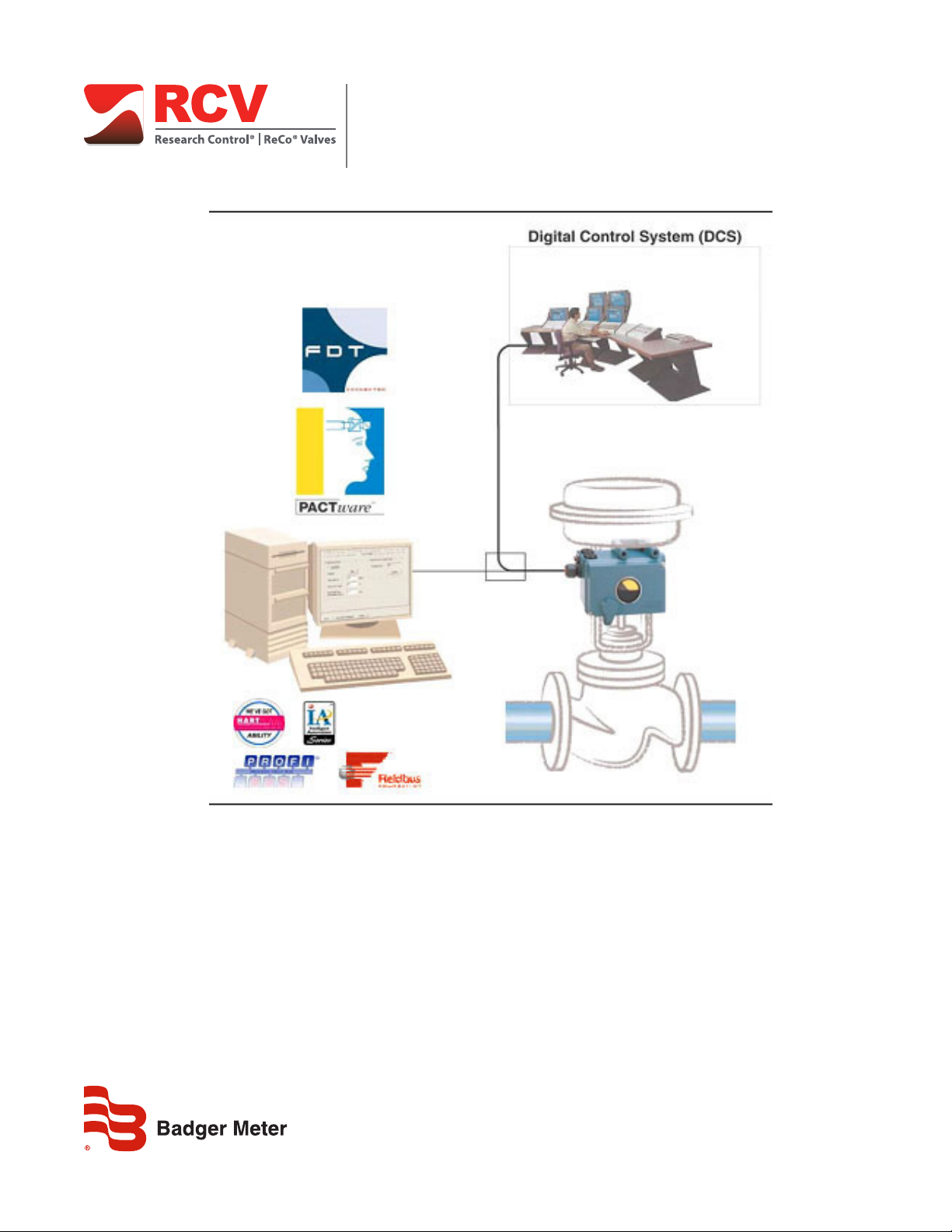
The valve diagnostic software VALcare is available as Device Type Manager (DTM) for integration into control systems based
on the Field Device Tool (FDT) technology such as the Foxboro IA Series System. It is designed to support methods for
evaluation of the valve health, operation and configuration. The DTMs support the communication protocols HART, Profibus
PA, FOUNDATION Fieldbus (FF) and FoxCom.
Features
• Predictive Maintenance capabilities
• Intelligent Alarm Management
• Self-surveillance in accordance with NE107
• Service Management
• Histograms for Valve Position- and Response-History
• Data collected up to 60 months
• Data stored inside positioner memory
• Determination of Stem Friction to prevent leakage and stuck stem
• Histogram for Friction-History
• Partial Stroke Test function for ESD applications
The software available as Device Type Manager (DTM) for Field Device Tool (FDT) -compliant PC’s or control systems
is designed to provide the identical functionality for each Intelligent Positioner, independent of what communication
protocol is used. All DTMs have the same look and feel and functionality. The following instruction shows details about the
configuration, operation and diagnostics of the Intelligent Positioner.
Intelligent Positioner
The intelligent positioner is designed to operate pneumatic valve actuators. This includes versions with analog setpoint
(4…20 mA) without communication or with superimposed HART signal; digital with FoxCom protocol, or fieldbus
communication according to PROFIBUS-PA and FOUNDATION
Fieldbus H1 based on IEC 1158-2 MBP acc. to FISCO. Before connecting electrical power and utilizing this program to
communicate with and operate the positioner.
Before using the VALcare software ensure that you have observed the following:
• All documentation such as the Product Specification Sheets (PSS) and the Master Instructions (MI) is thoroughly reviewed.
• The positioner is mounted on a valve / actuator per requirements of the MI.
WHAT IS FDT / DTM?
The FDT/DTM concept specifies a “frame application” with a uniform platform for software tools and provides the particular
advantage of a simple, standardized and common implementation and engineering environment to integrate field devices
into any FDT compliant control system.
It defines interfaces and mechanisms which provide a simple method of running a type of “printer driver” for field devices,
the Device Type Manager (DTM). DTM describe the field device specific software component. VALcare is such a “driver” and
supports the communication protocols HART, Profibus PA, FOUNDATION Fieldbus and FoxCom. FDT supplements the DDL
technology and offers much more, a unified architecture for all devices in a plant. Benefit, the “driver” can be integrated into
any FDT compliant control system.
Page 7 August 2014 POS-UM-00011-EN-02

Contents of VALcare Software
CONTENTS OF VALCARE SOFTWARE
The VALcare -software package includes the following files:
PACTware with:
• PACTware Release 3.0
• ComDTM for the HART Protocol (by Codewright)
srdinstall with:
• Device DTM for SRD991 and SRD960 for HART, PROFIBUS, FOUNDATION F. and FoxCom
modeminstall with:
• ComDTM for the FoxCom / EDCom / IRCom Protocol
Hardware Requirements
A computer with Pentium II 200 MHz processor or better, XGA Graphics and a Microsoft®-compatible mouse or an equivalent
pointing device is recommended.
Disk space requirements:
PACTware 100 MByte
ComDTM 40 MByte
DeviceDTM 55 MByte
Main Memory 45 MByte
Software Requirements
PACTware runs under the operating systems Windows NT 4.0 as of Service Pack 4, Windows 2000 and Windows XP. To print
device parameter values, a Microsoft Internet Explorer as of Release 4.0 must be installed.
About the Software
PACTware (Process Automation Configuration Tool) is a program which allows to select communication-capable field devices
of different manufacturers from a device catalog and combine them in projects.
In accordance with the FDT Specification 1.2 (Field Device Tool Specification) PACTware is used as a frame program for the
VALcare or any other Device DTM (Device Type Manager). VALcare is a full version software for predictive maintenance,
diagnosis, configuration and calibration.
Via ComDTM (Communication DTM), a communication with the field devices using protocols like the HART, PROFIBUS,
FOUNDATION F. or FoxCom protocol is established.
VALcare Includes Communication and Device DTMs
HART PROFIBUS-PA FOUNDATION F. FoxCom / EDCom / IRCom
Communication DTM √
Device DTM
SRD991 √ √ √ √
SRD960 √ √ √ √
Required Modems and Interfaces
HART HART-Modem (Serial or USB)
PROFIBUS-PA PROFICard by Softing
FOUNDATION F. ATFBus by National Instruments
FoxCom PC10-Modem
EDCOM EDC82 / EDC83 Modem
IRCOM IR-Modem (Serial or USB)
Communication driver
distributed by Softing
Communication driver
included in FBM
√ Communication driver
included in modeminstall.exe
How to Order
The CD-Rom for the VALcare Software package can be ordered under No: EW 556 932 011.
Page 8 August 2014POS-UM-00011-EN-02
Installation
INSTALLATION
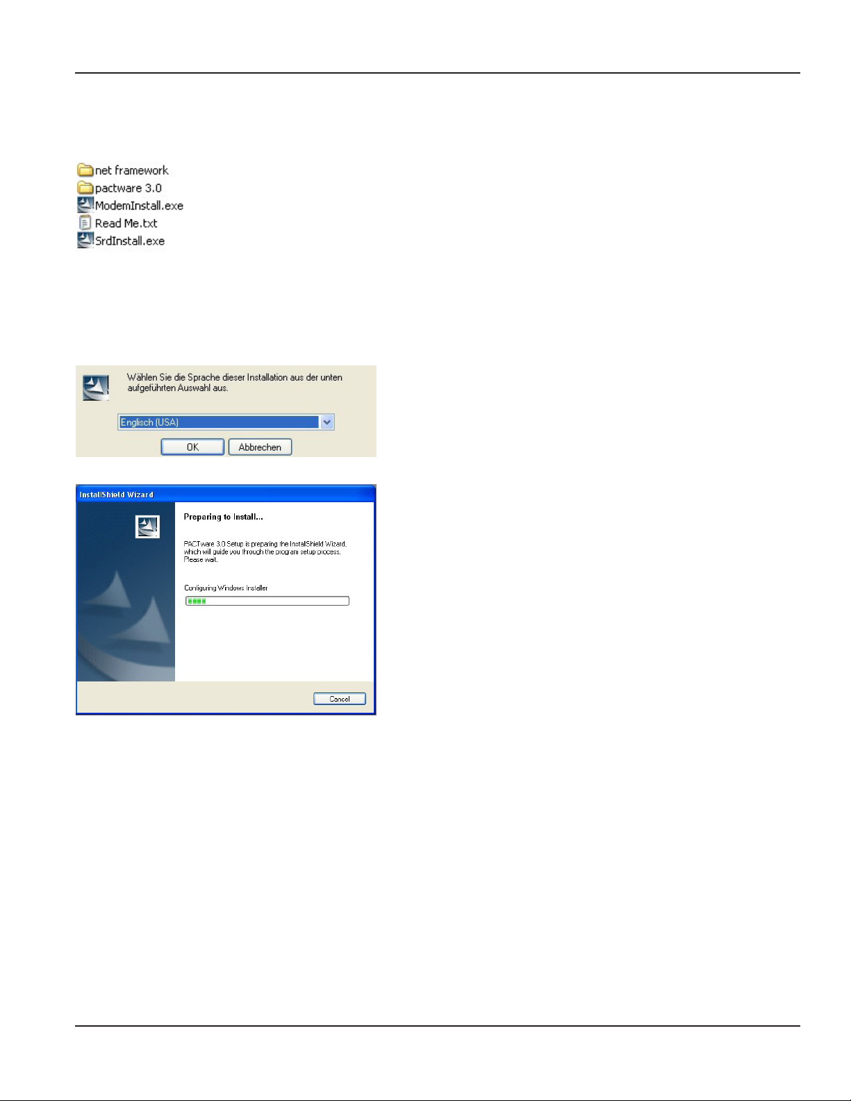
The following files are available on the VALcare CD-ROM:
OTE:N If PACTware 3.0 is not yet installed, start here. If PACTware 3.0 is installed, go to “Installing Comm DTM” on page9.
Installing .net Extension
Install the .net extension if your system is based on Windows® NT 4.0 as of Service Pack 4, Windows 2000 or Windows XP.
Installing PACTware
1. Click setup.exe.
2. Select a language.
3. Conrm the license agreement.
4. Select the setup type—either user-dened or complete.
The user-defined setup lets you specify a target directory for PACTware
and to exclude some components from the installation.
The setup wizard guides you though the installation.
OTE:N If PACTware 3.0 is already installed, start here.
Installing Comm DTM
To install FoxCom, EDCom and IRCom Device DTM:
1. Click modeminstall.exe.
2. Conrm the license agreement.
3. Select the setup type—either user-dened or complete.
Page 9 August 2014 POS-UM-00011-EN-02
Installation
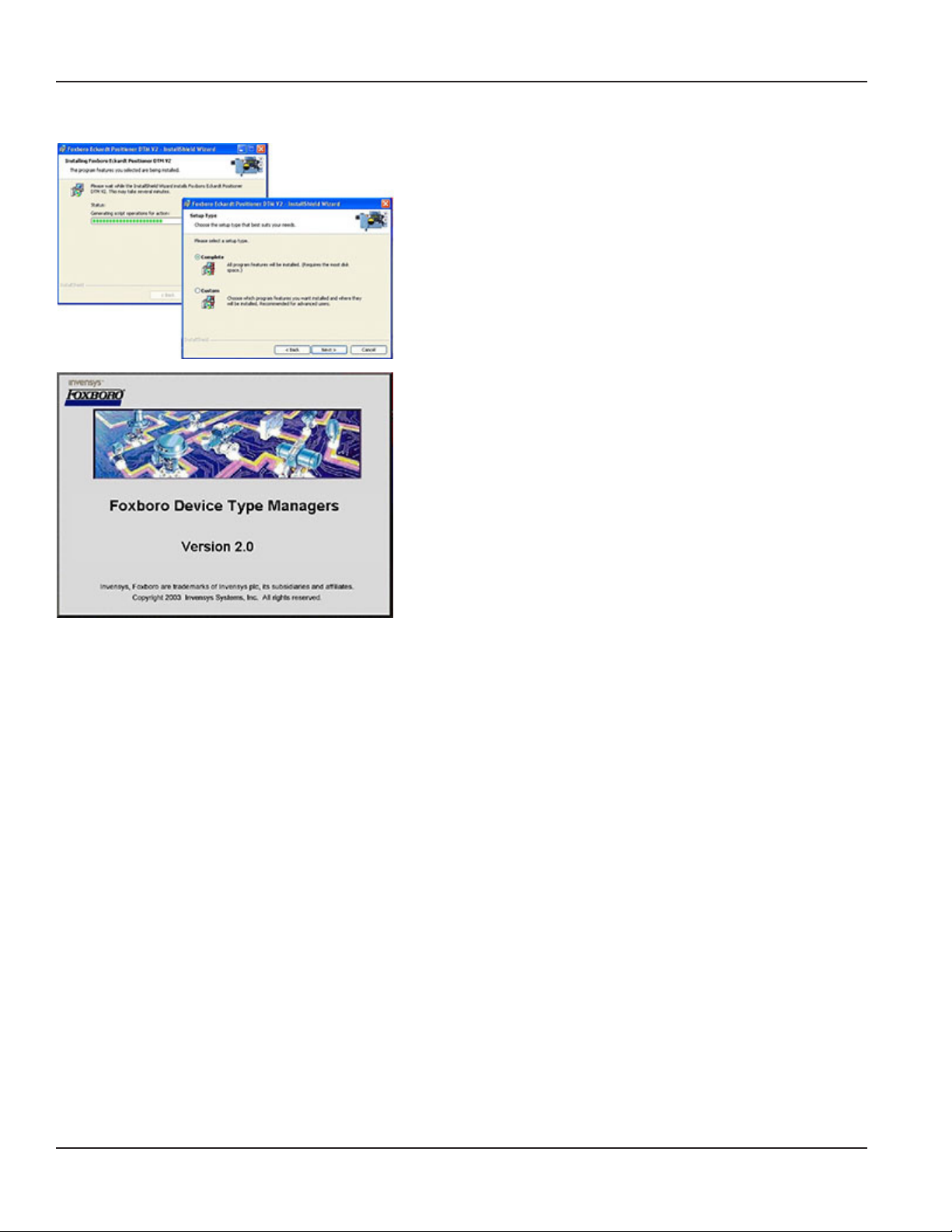
Installing an SRD Device DTM
1. Click srdinstall.exe.
2. Conrm the license agreement.
3. Select the setup type—either user-dened or complete.
We recommend using the complete setup.
After you select the setup type, the Foxboro DTM install shield opens.
When setup is complete, the install shield automatically closes.
Page 10 August 2014POS-UM-00011-EN-02
STARTING PACTWARE
PACTware Login
User Administration
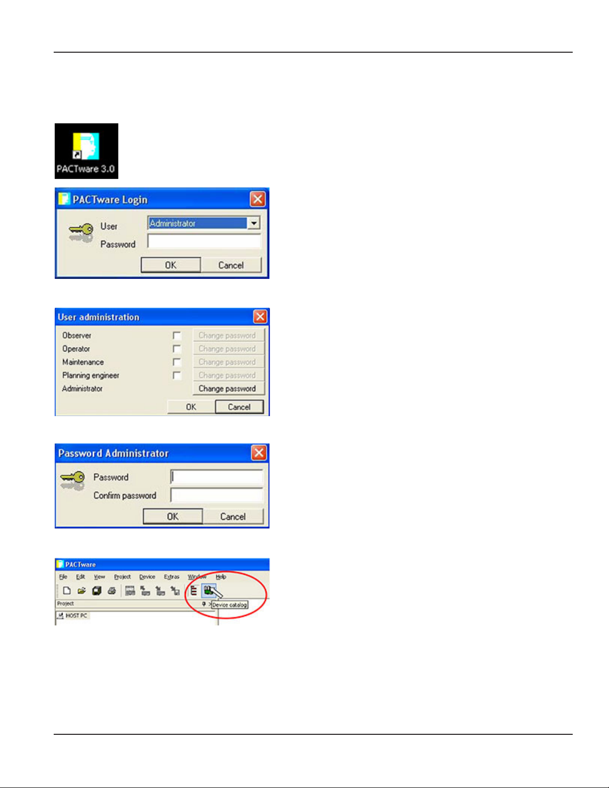
Starting PACTware
Click the PACTware 3.0 icon on your desktop.
The PACTware Login window opens.
The first time you access the software, you need to select a User type
and enter the default Password.
1. Select Administrator from the User menu.
2. Type manager (the default) in the Password eld.
To change the password:
1. Navigate to Extras > User Administration.
2. Select change password.
The Password Administrator screen opens.
Password Administrator
Updating the Device Catalog
We recommend not using a password, which lets each operator
access the PACTware Login screen by just clicking OK without entering
any password.
Leave the Password and Confirm password fields blank and click OK.
Click the Device catalog button.
Page 11 August 2014 POS-UM-00011-EN-02

Starting PACTware
Click the Update device catalog button.
The software scrolls through all device drivers (foxfdt…) to make sure
that the drivers are updated.
Page 12 August 2014POS-UM-00011-EN-02
OPENING A PROJECT
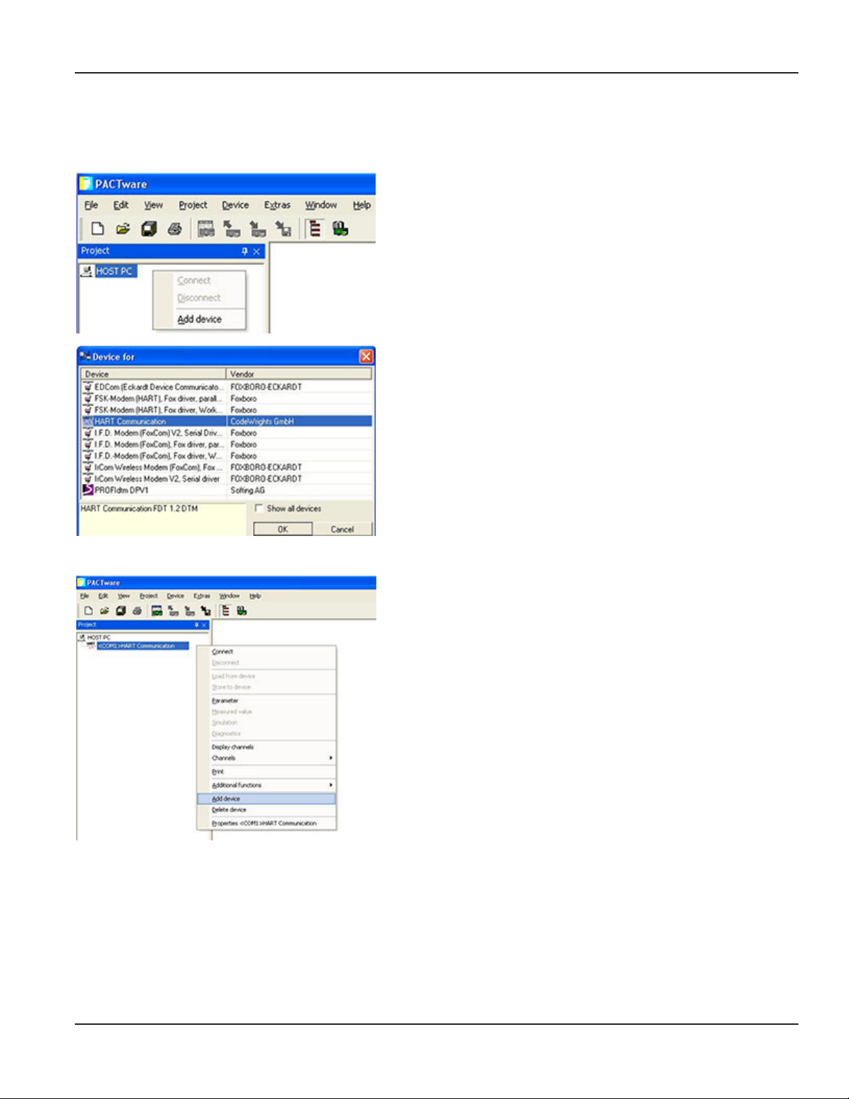
Adding a Communication Driver to the HOST PC
1. Start PACTware.
2. From the Project menu, select HOST PC.
3. Right-click and select Add device.
4. From the Device for window, select HART Communication.
5. Click OK.
Opening a Project
Adding a Device DTM to the Communication DTM
1. From the Project menu, select the HART Communication driver you
just added under HOST PC.
2. Right-click and select Add device.
Page 13 August 2014 POS-UM-00011-EN-02

Opening a Project
Selecting the Port / Channel
After adding the communication driver, you need to address a PORT or channel.
If you are running PACTware on a PC, the PORTs correspond to your
COM Ports. In this case, the standard Serial Port might be COM1 =
PORT1.
If you are running PACTware on the Foxboro I/A Series System in
connection with an FBM215 for 8 HART outputs, you will see each
individual channel of the FBM.
Connecting the Device
The displayed example represents the 8 channels (CHAN1…8) of a
Field Bus Module (FBM) connected to a Control Processor (CP).
After browsing the channels of the individual FBM, you can assign a
field device to each I/O.
1. From the Project menu, select a driver.
2. Right-click and select Connect.
When the drivers are successfully connected, the line turns bold and a
pound sign ( # ) is added to each line.
Page 14 August 2014POS-UM-00011-EN-02

Loading Data from a Device
Opening a Project
1. From the Project menu, select a device.
2. Right-click and select Load from device.
A status bar indicates that the data is loaded from the device.
The Project is now active.
Page 15 August 2014 POS-UM-00011-EN-02

Menu Structure
MENU STRUCTURE
Communication DTM for HART, FoxCom and PROFIBUS and FOUNDATION Fieldbus
Page 16 August 2014POS-UM-00011-EN-02

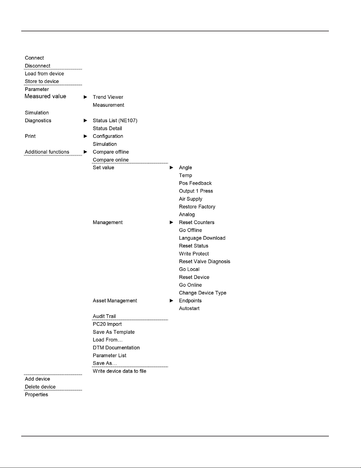
SRD-DTM for HART, FoxCom and PROFIBUS…
SRD-DTM before 01.07.2005
Menu Structure
Page 17 August 2014 POS-UM-00011-EN-02
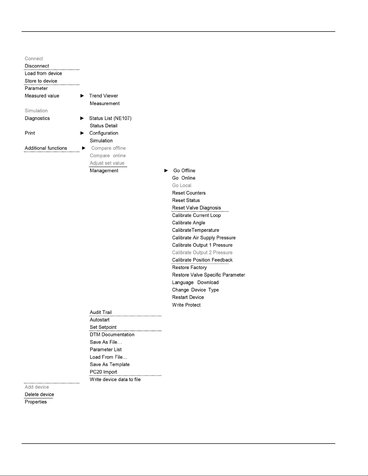
Menu Structure
SRD-DTM from 01.07.2005
Page 18 August 2014POS-UM-00011-EN-02

SRD-DTM from 02.09.2005
Menu Structure
Page 19 August 2014 POS-UM-00011-EN-02
Menu Structure
SRD-DTM from 17.10.2005
Page 20 August 2014POS-UM-00011-EN-02

SRD-DTM for FOUNDATION Fieldbus from 02.09.2005
Menu Structure
Page 21 August 2014 POS-UM-00011-EN-02

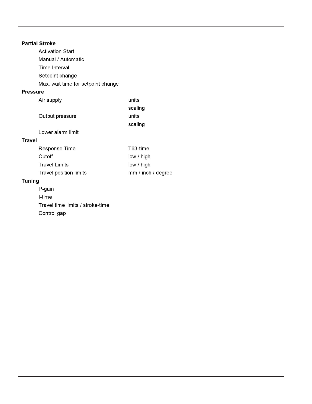
Menu Structure
Parameter
Page 22 August 2014POS-UM-00011-EN-02

Menu Structure
Page 23 August 2014 POS-UM-00011-EN-02
Menu Structure
Page 24 August 2014POS-UM-00011-EN-02

Diagnosis Detail
Menu Structure
Page 25 August 2014 POS-UM-00011-EN-02

Menu Structure
Diagnosis Detail continued
Page 26 August 2014POS-UM-00011-EN-02

Startup
STARTUP
The Startup menu includes the functions Autostart and Endpoints. The Autostart function allows a full adaptation of the
positioner to the actuator. The Endpoints function only does a determination of the mechanical stops and the IP parameters.
Mounting Conguration
Configure the mounting = Valve Stem Movement The Mounting configuration field is used to define the Valve stem movement from the following options:
• Linear, left mounted (globe valve, positioner spindle to the left of the valve stem)
• Linear, right mounted (globe valve, positioner spindle to the right of the valve stem)
• Rotary, CCW (quarter turn, counter-clockwise to open)
• Rotary, CW (quarter turn, clockwise to open)
OTE:N If the type field above shows a globe valve, this field defaults to Linear, left mounted.
A rotary valve in the type field will yield Rotary, CCW as the default. This feature is also available in the push button menu of
the positioner’s PCB.
Autostart
1. Select the designated calibration type (Cal Type).
2. Click Continue.
The status for each step of the Autostart displays.
Autostart Methods Before HW-Rev. 3.4 Autostart Methods for HW-Rev. 3.4 and Later
Two methods can be selected via the software. Five methods can be selected via the software.
SRD-DTM Local SRD-DTM Local
Full √ 2.1 Endpoints √ 2.1
Endpoints √ 2.2 Standard Autostart √ 2.2
Enhanced Autostart √ 2.3
Smooth Response √ 2.4
Fast Response √ 2.5
Page 27 August 2014 POS-UM-00011-EN-02

Startup
The Autostart process determines valve travel limits (zero, span) and tuning parameters. The procedure is executed in
four stages:
1. Determining the mechanical travel stops of the actuator.
2. Applying a series of ramps to determine the control system parameters for the IP-Module.
3. Applying a series of step-response tests to determine the control parameters.
4. Determining the stroke-time (T63-time).
By performing these steps, the valve is stroked several times and ramps are applied to the input signal.
IF THE AUTOSTART IS EXECUTED, IT WILL OPEN AND CLOSE THE VALVE AND IN RESULT DISTURB THE PROCESS.
Autostart Routine – Endpoints
The Endpoints routine determines only the mechanical stops of actuator/valve.
Executed steps during Autostart:
1. Determining the mechanical travel stops of the actuator.
2. Applying a series of ramps to determine the control system parameters for the IP-Module.
Autostart Routine – Standard Autostart
The Standard Autostart routine is recommended for standard applications. Executed steps during Autostart:
1. Determining the mechanical travel stops of the actuator.
2. Applying a series of ramps to determine the control system parameters for the IP-Module.
3. Applying a series of step-response tests to determine the control parameters.
4. Determining the stroke-time (T63-time).
Autostart Routine – Enhanced Autostart
The Enhanced Autostart routine has optimized control behavior compared to the Standard Autostart routine. Enhanced
Autostart executes the same steps as Standard Autostart, but with additional iterations.
Autostart Routine – Smooth Response
The Smooth Response routine has dampened control behavior (for example, for smaller actuators). Smooth Response executes
the same steps as Standard Autostart, but with different settings of the P-gain and I-time.
Autostart Routine – Fast Response
The Fast Response routine has undampened control behavior (for example, for larger actuators). Fast Response executes the
same steps as Standard Autostart, but with different settings of the P-gain and I-time.
Page 28 August 2014POS-UM-00011-EN-02

Startup
Autostart Duration and Success
The duration of Autostart depends on the actuator size (volume) and hysteresis of the actuator. For small actuators, it may only
take a few minutes, whereas actuators with large volumes may require significantly longer times. The time can be reduced in
some cases by using the spool valve version or by applying a volume booster. Each of the stages in the Autostart process will
be identified by the LCD and/or red+green LEDs.
If Autostart is not successful, it may terminate before reaching the last step, which means that the positioner is not properly
calibrated. To check whether Autostart is successfully completed, select Valve Status from the Test option in the main menu.
Potential reasons for an Autostart not being successful are:
• Positioner mounting problem. Feedback lever or coupling in wrong orientation.
• Inadequate supply pressure
• Large actuator. Use Endpoint calibration and tune manually. Employ boosters to increase output capacity.
• Hardware problem
If Autostart cannot be successfully executed, see “Endpoint Calibration” on page29.
The Autostart feature can also be manually accomplished at the positioner by push buttons.
Endpoint Calibration
This function will automatically detect the valve end points. It accomplishes this by using only the first of the four autostart
steps. This process determines the valve mechanical travel stops, zero and span but not the tuning set. Accordingly, it
requires much less time than a full Autostart. If the tuning parameters are available for the control valve from previous testing
or existing data, then Endpoints calibration and manually entering tuning parameters (previous section) will shorten the
positioner setup time significantly.
Page 29 August 2014 POS-UM-00011-EN-02
Measured Value
MEASURED VALUE
Trend Viewer
Measurement
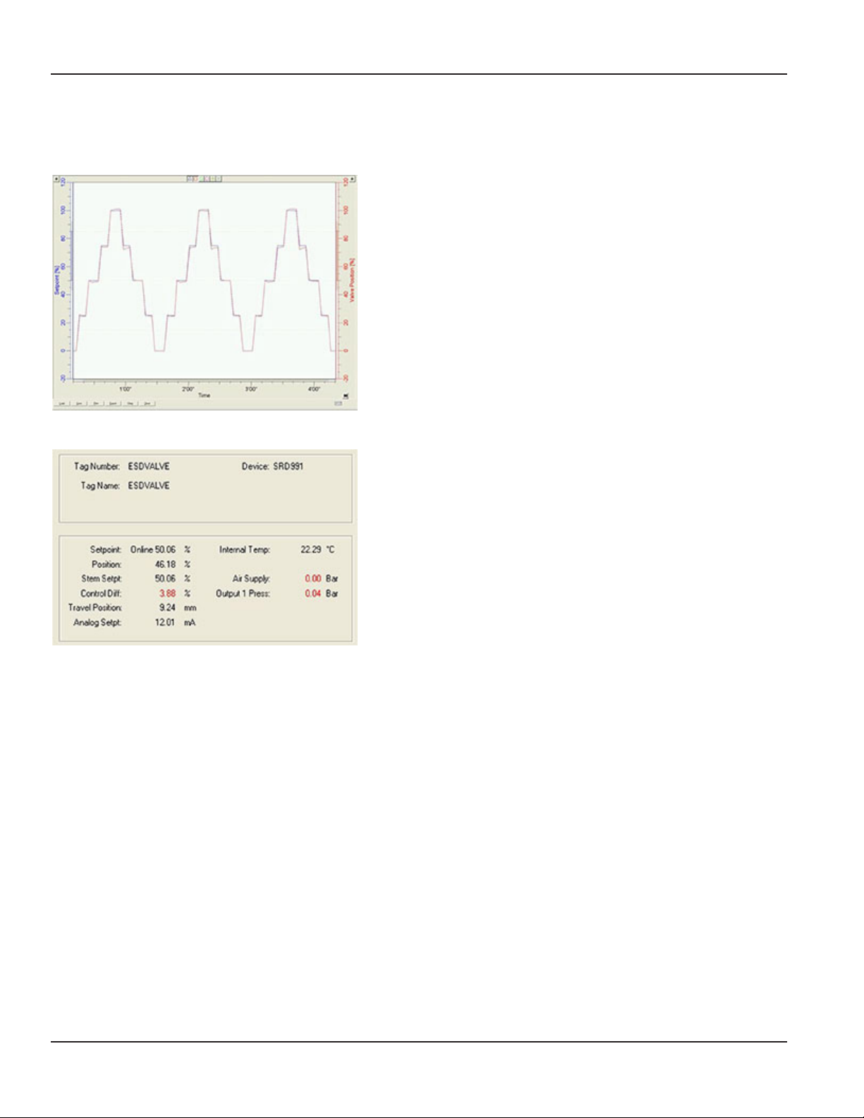
With the Trend Viewer the different values over time can be displayed.
This trending tool collects and displays important ‘live’ data of the
positioner. The graphs could be used to check the control behavior and
the ‘valve health’.
With the Setpoint function it is possible to change the setpoint of the
valve and display the measured data of the positioner. It is possible to
print and store the tending results.
The measurement page is designed to display the most important
information, as in the following examples.
For identification:
• Tag Number
• Tag Name
• Device
For the process data:
• Setpoint
• Position
• Stem Setpoint
• Control Difference
• Travel Position
• Analog Setpoint / Loop Current
• Internal Temperature
• Air Supply Pressure
• Output Pressure 1 / 2
Setpoint
This value shows the digital setpoint in percent and provides a read back of the setpoint value that is sent to the positioner.
(Default range is: 0.0 to 100.0 %). If the valve does not move upon a setpoint change, the user should check the following:
Position / Valve Position
This value shows the actual valve position in percent. The normal operating range for the valve position is 0 to 100% of the
full travel.
Page 30 August 2014POS-UM-00011-EN-02
 Loading...