

Page 1
Flow Sensors
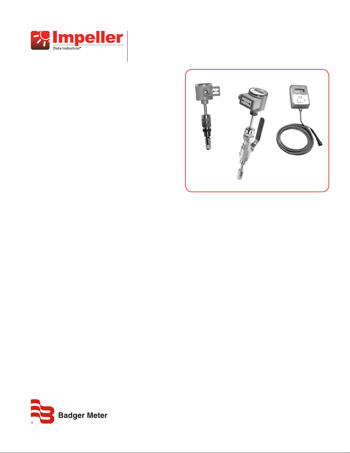
Insert Style Flow Sensors
SDI Series
DESCRIPTION
The Data Industrial SDI Series insert flow sensors from
Badger Meter offer accurate liquid flow measurement in closed
pipe systems in an easy to install economical package. Impeller
sensors offer a quick response to changes in flow rate and are well
suited to flow control and batch type applications in addition to
flow monitoring. The four-bladed impeller design is rugged,
non-fouling and does not require custom calibration. Coupled
with the proprietary patented digital detection circuit, the sensor
measures flows from under 0.5 ft/sec (0.15 m/sec) to more than
20 ft/sec (6.1 m/sec) regardless of the conductivity or turbidity
of the liquid. The standard frequency output produces a low
impedance square wave signal proportional to flow rate that may
be transmitted up to 2000 ft (610 m) without amplification. The
SDI Series includes:
• Single direction powered insert with raw, scaled pulse and
analog output
• Bidirectional powered insert with analog and scaled
pulse output
• Battery powered insert with a local or remote display and
scaled pulse output
HOT TAP SENSORS OPTIONAL
APPLICATIONS
SDI insert style flow sensors are intended for general clean liquid
flow measurement applications. They are available in either brass
or stainless steel construction.
FUNCTIONALITY
These insert style sensors are intended for direct installation into
pipelines through a 1 in. (25 mm) tap. The pipeline must be out
of service and not under pressure at the time of installation. For
any pipeline that is in service at the time of installation or cannot
be de-pressurized and drained for service, the SDI hot tap model
equipped with isolation valves is recommended.
Three different stem lengths in both the direct insert and hot tap
versions accommodate pipe diameters 1-1/2…36 in. (38…914 mm)
depending on the pipe material and tapping methods. Larger sizes
usually require the use of hot tap models.
In pipe sections with at least 10 diameters of straight pipe
upstream of the sensor and 5 diameters of straight pipe
downstream, accuracies of ±1% of rate may be achieved when
the flow sensor is installed at the correct insertion depth and
properly aligned.
Hot tap sensors feature an isolation valve and mounting hardware
to install or remove the sensor from a pipeline that would be
difficult to shut down or drain. In a true hot tap installation the
sensor is mounted in the pipe under pressure by attaching a service
saddle or weld-on fitting to the pipe and mounting the isolating
valve to the threaded connection. A hole is then cut in the wall of
the pipe through the valve using a commercial tapping machine
with a 1 in. size cutter. Once the hole is cut, the tapping machine
is removed and the valve is shut. Then the sensor assembly is
mounted to the isolation valve and extended into the pipeline
to measure flow. Even in new construction a hot tap sensor may
be appropriate for service considerations. The hot tap sensor is
constructed of 316 stainless steel and is rated for service to 1000
psi at 70° F (21° C) (see “Maximum Pressure Rating for SST Stem” on
page 4). The sensor installs in a 1 in. NPT tap for both wet and
dry installations. The small stem diameter allows the sensor to be
inserted into the pressurized pipeline by hand without the need for
an installation tool. Mounting hardware holds the sensor firmly in
place at the correct depth and alignment.
BATTERY POWERED SENSORS OPTIONAL
Battery powered versions are complete flow measuring systems
providing a local or remote programmable display of rate, total
or both, powered by a C size lithium battery that has a five year
life span.
SEN-DS-01382-EN-07 (May 2017)
Product Data Sheet
Page 2

Flow Sensors, Insert Style Flow Sensors
OUTPUT CONFIGURATIONS
Standard Frequency
Sensor output is a pulse proportional to flow. The signal is similar to all 200 Series flow sensors and will interface with all existing Data
Industrial transmitters and monitors. The power supply to the sensor and the output signal from the sensor is carried on the same two wires.
Wire connections are made at screw terminals on removable headers inside the NEMA 4X housing.
Analog Output
The sensor is also available with a two-wire loop powered 4…20 mA output. The analog output is produced by an onboard
micro-controller for precise, drift-free signals. Sensors may be preprogrammed at the factory or field programmed using the a computer
with the programming kit and Windows® based software program. All information is stored in the flow sensor nonvolatile memory.
Scaled Pulse Output
The scaled pulse is produced by an onboard micro-controller for precise, accurate outputs. This option may be programmed to produce an
isolated solid state contact closure scaled to any number of engineering units of measure. Sensors may be preprogrammed at the factory
or field programmed using the a computer with the programming kit and Windows® based software program. All information is stored in
nonvolatile memory in the flow sensor. This is a four-wire option.
Bidirectional Flow, Analog Output
This option provides a programmable 4…20 mA signal proportional to flow rate and a contact closure to indicate the direction of flow. The
unit may be preprogrammed at the factory or field programmed using a computer with the programming kit and Windows® based software
program. The user can program the unit for pipe size, flow scale and the direction of flow. This is a six-wire option.
Bidirectional Flow, Scaled Pulse Output
This option provides the user with a choice of outputs. In one case the sensor provides an output scaled to the required number of
engineering units on one set of terminals and a contact closure to indicate the direction of flow on another. The other choice provides
two isolated scaled pulse outputs, one for each direction. Programming the output choice, pipe size, output scale and direction of flow by
the user are also accomplished by using a computer with the programming kit and Windows® based software program. This option also
requires six wires.
Display Options
All models except the standard frequency output version may also be equipped with a display. Integrated into the NEMA 4X housing, the
eight digit LCD may be programmed to show rate of flow, flow total or toggle between the two. Bidirectional models also show
flow direction.
The eight character 3/8 in. LCD is mounted on the sensor visible through a lens at the top of the electronics housing.
For battery powered versions only, an optional remote display is available where the LCD is located in a wall mount NEMA 4 enclosure. The
remote may be connected to the flow sensor up to a maximum of 50 ft (15 m) away using extension cables.
Page 2 May 2017
SEN-DS-01382-EN-07
Page 3

SPECIFICATIONS
Product Data Sheet
Sensor stem,
Wetted Materials
Sensor Tip
O-rings, Bearings, Shaft See ordering matrix
Operating Temperature
Maximum Pressure Rating
Stainless Steel (Non Shock)
Optimum Design Flow
Range
Pressure Drop 0.5 psi or less at 10 ft/sec (3 m/sec.) for all pipe sizes 1.5 in. (38 mm) diameter and up
Accuracy Standard: to ±1% of rate over optimum flow range
Straight Pipe Requirement
Repeatability ±0.5%
Enclosure
Programming
Display (Optional)
Accessories
mounting adapter,
isolation valve,
and nipple:
Polyphenylene sulfide (PPS)
Polyetheretherketone (PEEK)
Electronics 14…150° F (–10…65° C)
LCD –4…150° F (–20…65°C)
1000 psi (68.9 bar) @ 70° F (21° C)
900 psi (62 bar) @ 100° F (37.8° C)
670 psi (46.1 bar) @ 140° F (60° C)
225 psi (15.5 bar) @ 180° F (82° C)
600 psi (41.3 bar) @ up to 140° F (60° C)
225 psi (15.5 bar) @ 180° F (82° C)
1…20 ft/sec. (0.30…6 m/sec.)
Extended flow range < 0.5…20 fps
Install sensor in straight pipe section with a minimum distance of 10 diameters upstream and
5 diameters downstream to any bend, transition, or obstruction.
Sensor- battery Polypropylene with Viton® sealed acrylic cover. Meets NEMA 6P specifications
Sensor Polypropylene with Viton® sealed acrylic cover. Meets NEMA 4X specifications
Remote Polycarbonate w/ Neoprene® sealed cover. Meets NEMA 4X specifications.
Battery powered
version
Bidirectional, pulse,
and analog versions
8 character, 3/8 in. (10 mm) LCD
STN (Super Twisted Nematic) display
Annunciators for rate, total, totalizer multipliers, low battery, flow direction
USB to DIC converter programming kit (840134-0002)
ASDIB-20 programming kit- battery powered A-301 connector cable or USB
Battery powered
version
316 Stainless steel
Brass, B16, UNS C36000
A-303 connector cable and SDI Series software
USB to DIC converter programming kit (840134-0002)
07101 5 ft (1.5 m) extension cable
07108 10 ft (3 m) extension cable
07102 20 ft (6 m) extension cable
07109 50 ft (15 m) extension cable
SEN-DS-01382-EN-07
Page 3 May 2017
Page 4

Flow Sensors, Insert Style Flow Sensors
PSIG
• 225 PSI up to 180°F
Power Specications
Unidirectional Bidirectional Battery
Raw Pulse
Option 0
Number of Wire Connections
Operating Voltage 8…35V DC n/a
Overvoltage
Protection
Quiescent Current
Draw
@ 12V DC or 24V AC
Pulse
Units
Analog
Units
The battery operated version is powered by a C size lithium battery with a five year life span
Short Circuit Current 50 mA typical n/a > 100 mA
Output Frequency 800 Hz max n/a
Output Pulse Width
Output Isolation n/a n/a Opto-isolated Opto-isolated Opto-isolated Opto-isolated
Operating Voltage n/a 8…25V DC n/a 8…25V DC n/a n/a
Output Response
Time
2 2 4 6 6 2
30V AC
± 40V DC
330 µA typical
5 mS below
100 Hz
n/a
Analog Loop
Option 1
± 40V DC
Software-controlled
current of
3.5…20.5 mA
n/a
Varies with
programmable filter
Scaled Pulse
Option 2
12…30V AC
12…35V DC
30V AC
± 40V DC
< 2.0 mA < 5.0 mA < 5.0 mA n/a
For direction >
Scaled by
customer
Adjustable
50 mS to 5.0
seconds in
50 mS
increments
n/a
programmable
Analog Loop
Option 5
12…30V AC
12…35V DC
30V AC
± 40V DC
100 mA
n/a
n/a
Varies with
filter
Operated
Scaled Pulse
Option 6
12…30V AC
12…35V DC
30V AC
± 40V DC
> 100 mA > 100 mA
Scaled by
customer
Adjustable
50 mS to 5.0
seconds in
50 mS
increments
n/a n/a
Scaled Pulse
Option 2
n/a
n/a
Scaled by
customer
Selectable
50 mS
100 mS
250 mS
Maximum Pressure Rating for SST Stem
(Note: PPS or PEEK Tip)
1000
900
800
700
600
500
400
300
200
100
Pressure vs. Temp [non-shock]
PEEK*
PPS*
70 100 140 180 220 260 300
* Max. Pressure Temp. Ratings for Brass:
• 600 PSI up to 140°F
Page 4 May 2017
SEN-DS-01382-EN-07
Page 5

ORDERING MATRIX
SDI Series Single Direction Insert Powered Version Ordering Matrix
SDI 0 H1 N 0 0 - 0 2 0 0
MATERIAL
Stainless Steel / PPS Tip 0
Brass / PPS Tip (not available with hot tap)
Stainless Steel / Peek Tip 2
TYPE
Direct Insert for Pipe 1½" - 10" * D1
Direct Insert for Pipe 12" - 36" * D2
Direct Insert 36" and UP* D3
Hot Tap for Pipe 1½" - 10" * H1
Hot Tap for Pipe 12" - 36" * H2
Hot Tap for Pipe 36" and UP * H3
ELECTRONIC HOUSING
NEMA 4X N
OUTPUT
Standard Frequency Pulse 0
Analog 4-20mA 1
Scaled Pulse 2
DISPLAY
No Display 0
LCD Option (requires output option 1 or 2)
O-RING
Viton® 0
EPDM 1
AFLAS 2
SHAFT
Tungsten Carbide [Standard] 2
Hastelloy®C-276 [optional - consult factory] 1
IMPELLER
Stainless Steel 0
BEARING
®
Torlon
Ketron 2
1
Product Data Sheet
1
0
* Pipe size is for reference only. Depending on pipe size, tapping saddle or existing hardware, longer sensor length may be required. Consult the factory. For
material details, consult the factory.
SEN-DS-01382-EN-07
Page 5 May 2017
Page 6

Flow Sensors, Insert Style Flow Sensors
1
Torlon
0
SDI Series Bidirectional Insert Powered Ordering Matrix
SDI 0 H1 N 5 0 - 0 2 0 0
MATERIAL
Stainless Steel / PPS Tip 0
Stainless Steel / PEEK Tip 2
TYPE
Hot Tap for Pipe 1½" - 10" * H1
Hot Tap for Pipe 12" - 36" * H2
Hot Tap for Pipe 36" and up* H3
ELECTRONIC HOUSING
NEMA 4X N
OUTPUT
Bi-Directional 4-20mA + Direction 5
Bi-Directional Scaled Pulse 6
DISPLAY
No Display 0
LCD Option 1
O-RING
Viton® 0
EPDM 1
AFLAS 2
SHAFT
®
Hastelloy
IMPELLER
Stainless Steel 0
BEARING
Ketron 2
C-276 [optional - consult factory]
®
2Tungsten Carbide [Standard]
* Pipe size is for reference only. Depending on pipe size, tapping saddle or existing hardware, longer sensor length may be required. Consult the factory. For
material details, consult the factory.
Page 6 May 2017
SEN-DS-01382-EN-07
Page 7

SDI Series Battery Powered Ordering Matrix
Brass / PPS Tip (not available with hot tap) 1
1
Torlon
®
0
MATERIAL
Stainless Steel / PPS Tip 0
Stainless Steel / PEEK Tip 2
TYPE
Direct Insert for Pipe 1-1/2" thru 10" * D1
Direct Insert for Pipe 12" thru 36" * D2
Direct Insert 36" and UP* D3
Hot Tap for Pipe 1-1/2" thru 10" * H1
Hot Tap for Pipe 12" thru 36" * H2
Hot Tap for Pipe 36" and UP * H3
ELECTRONIC HOUSING
Battery Powered/NEMA 6 B
OUTPUT
No Output N
Scaled Pulse 2
2 Pulse Output 9
DISPLAY
LCD Option 1
Remote Display/NEMA 4X 2
O-RING
Viton® 0
EPDM 1
AFLAS 2
SHAFT
®
Hastelloy
IMPELLER
Stainless Steel 0
BEARING
C-276 [optional - consult factory]
Product Data Sheet
SDI 0 D1 B N 1 - 0 2 0 0
2Tungsten Carbide [Standard]
* Pipe size is for reference only. Depending on pipe size, tapping saddle or existing hardware, longer sensor length may be required. Consult the factory. For
material details, consult the factory.
SEN-DS-01382-EN-07
Page 7 May 2017
Page 8

Flow Sensors, Insert Style Flow Sensors, SDI Series
Control. Manage. Optimize.
Data Industrial is a registered trademark of Badger Meter, Inc. Other trademarks appearing in this document are the property of their respective entities. Due to continuous
research, product improvements and enhancements, Badger Meter reserves the right to change product or system specications without notice, except to the extent an
outstanding contractual obligation exists. © 2017 Badger Meter, Inc. All rights reserved.
www.badgermeter.com
The Americas | Badger Meter | 4545 West Brown Deer Rd | PO Box 245036 | Milwaukee, WI 53224-9536 | 800-876-3837 | 414-355-0400
México | Badger Meter de las Americas, S.A. de C.V. | Pedro Luis Ogazón N°32 | Esq. Angelina N°24 | Colonia Guadalupe Inn | CP 01050 | México, DF | México | +52-55-5662-0882
Europe, Eastern Europe Branch Oce (for Poland, Latvia, Lithuania, Estonia, Ukraine, Belarus) | Badger Meter Europe | ul. Korfantego 6 | 44-193 Knurów | Poland | +48-32-236-8787
Europe, Middle East and Africa | Badger Meter Europa GmbH | Nurtinger Str 76 | 72639 Neuen | Germany | +49-7025-9208-0
Europe, Middle East Branch Oce | Badger Meter Europe | PO Box 341442 | Dubai Silicon Oasis, Head Quarter Building, Wing C, Oce #C209 | Dubai / UAE | +971-4-371 2503
Slovakia | Badger Meter Slovakia s.r.o. | Racianska 109/B | 831 02 Bratislava, Slovakia | +421-2-44 63 83 01
Asia Pacic | Badger Meter | 80 Marine Parade Rd | 21-06 Parkway Parade | Singapore 449269 | +65-63464836
China | Badger Meter | 7-1202 | 99 Hangzhong Road | Minhang District | Shanghai | China 201101 | +86-21-5763 5412
Switzerland | Badger Meter Swiss AG | Mittelholzerstrasse 8 | 3006 Bern | Switzerland | +41-31-932 01 11
Legacy Document Numbers: DTB-001-05-EN, DTB-002-04-EN, DTB-066-03-EN
 Loading...