

Page 1
Vortex Flow Meter
RVL Series
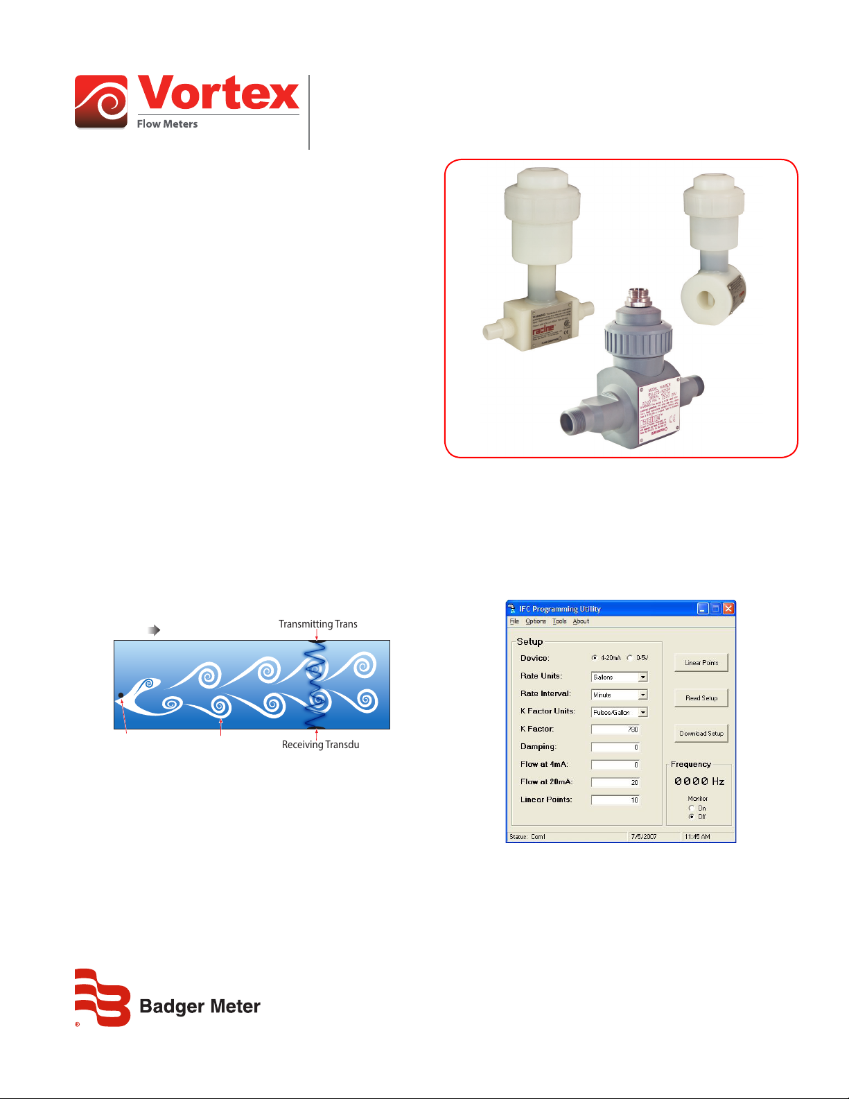
DESCRIPTION
The RVL liquid flow meter uses vortex-shedding technology with
embedded piezoelectric pressure sensors. The meter has no moving
parts, and any potential for fluid contamination is eliminated by the
non-metallic corrosion-resistant body materials. The meter includes
a compact plug-in transmitter module with two-wire 4…20 mA or
three-wire pulse output. All electronics are housed in a corrosionresistant enclosure. Units can be recalibrated and reprogrammed in
the field.
APPLICATION
The RVL is perfect for aggressive or easily contaminated fluids.
• Ultra-pure water distribution
• RO/DI skids
• Cooling water
• Chemical injection
• Nonabrasive slurries
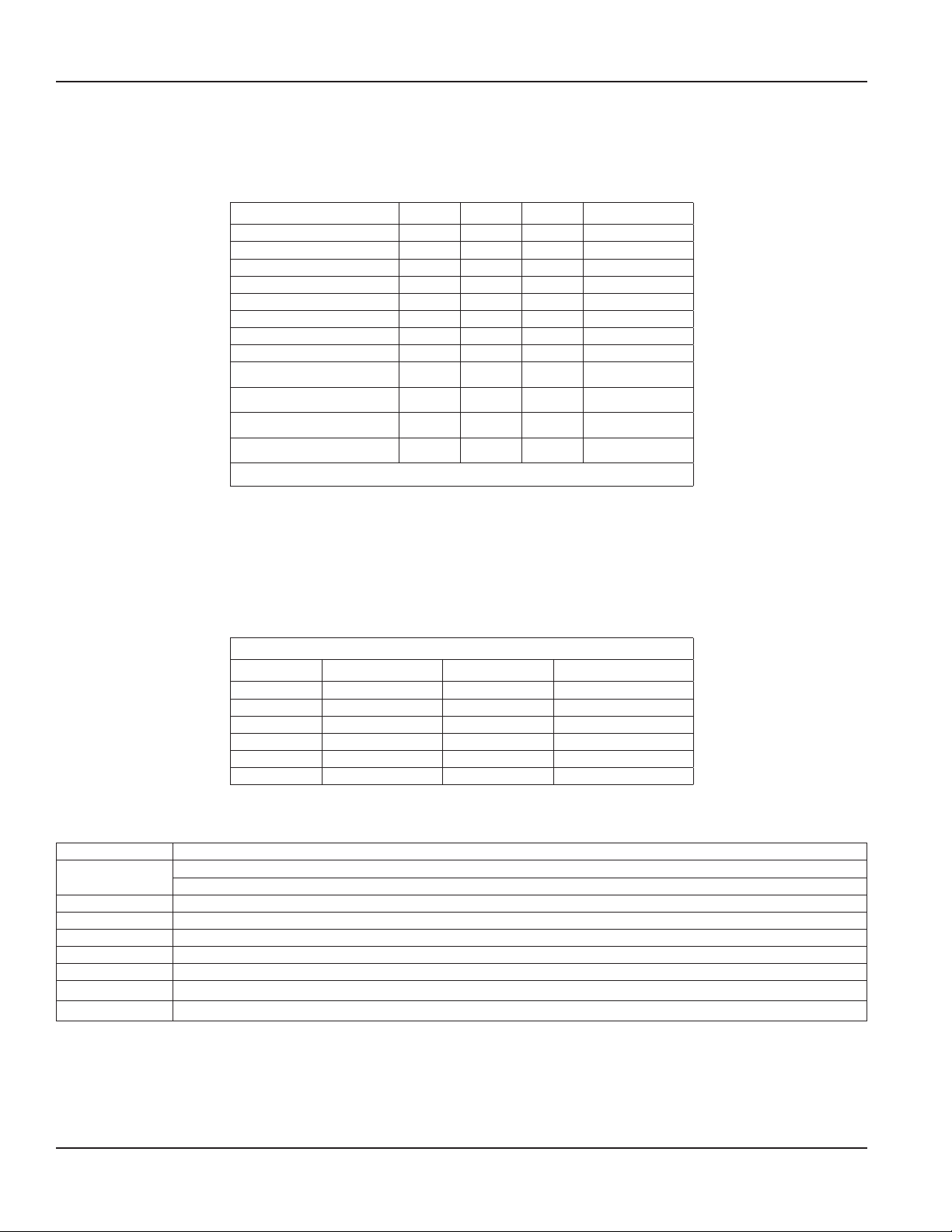
OPERATING PRINCIPLE
Operation of the RVL vortex flow meter is based on the vortex
shedding principle. As fluid moves around a strut, vortices (eddies)
are formed and move downstream. They form alternately, from
one side to the other, causing pressure fluctuations that are sensed
by a piezoelectric crystal in the sensor tube. The frequency of the
vortices is directly proportional to the flow rate.
FLOW
Small Strut
Shed Vortices
Transmitting Transducer
Receiving Transducer
CONSTRUCTION
The precision machined bodies provide quality end fittings, while
avoiding ionic contamination. There are no metallic wetted parts,
gaskets or elastomers in the meter. The body material selected is
homogeneous throughout the flow path.
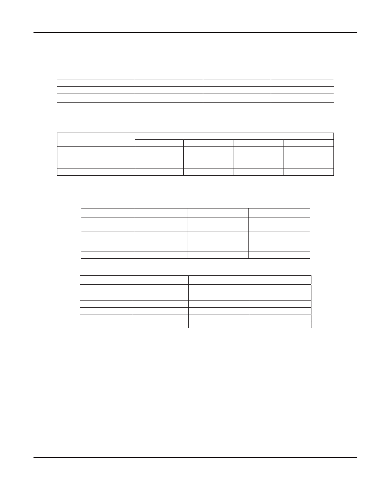
OPTIONAL SOFTWARE
An optional software utility kit is available to configure the RVL
4…20 mA output. (The pulse output is not field configurable.) Part
number RVS220-954 contains a RS232 nine-pin cable, software
CD, TTL to RS232 converter and a board interface cable. The
program enables easy configuration of span, damping and units of
measurement.
VRX-DS-01586-EN-08 (April 2019)
Product Data Sheet
Page 2
Material Selection
MATERIAL SELECTION
When choosing the best flow meter for a process, review the concentration, operating temperatures and operating pressure of the fluid
being measured. In a thermoplastic piping system, choose the same material for the meter and the pipe wherever possible to maintain fluid
compatibility and aid in bonding the materials. The table below shows the compatibility of fluid types with thermoplastic materials.
Chemical PVC PVDF CPVC Polypropylene
Aluminum Hydroxide A A A A
Chlorine Water A B A D
Fuel Oils A B — A
Hydraulic Oil A A — D
Hydrochloric Acid 37% B A A C
Hydrochloric Acid 20% B A C A
Isopropyl Alcohol A — C A
Nitric Acid (Concentrated) B A D D
Phosphoric Acid (>40%) B B A A
Potassium Hydroxide A A A A
Propylene Glycol C — C A
Sulfuric Acid (10…75%) A A A A
A= Excellent B= Good C= Fair D= Severe effect
FLUID CONSIDERATIONS
In vortex flow meters, fluids with high viscosities tend to dampen the formation of vortices and reduce the effective range. Viscosities above
1 cSt raise the minimum readable flow rate, reducing rangeability. The effect is linear to viscosity. Particles and internal bubbles do not
usually affect vortex meters. In slurry services, PVDF models typically work very well. Slurries containing grit can wear down the bluff body
over a period of time and long fibers can catch and build up on the bluff, decreasing accuracy.
Liquids with specific gravities higher than 2.0 adversely affect the permissible amount and duration of over-flow range.
Reduction of Range Based on Viscosity
Viscosity Minimum Maximum Flow Range
1 cSt 1 12 12:1
2 cSt 2 12 6:1
3 cSt 3 12 4:1
4 cSt 4 12 3:1
5 cSt 5 12 2.4:1
6 cSt 6 12 2:1
Meters are calibrated with tap water at 1 cSt (32 SSU) at ambient temperature
SPECIFICATIONS
Measured Fluids Liquids
Connections
Accuracy ±1% of full scale, 4…20 mA; ±2% of full scale, frequency pulse
Repeatability ±0.25% actual flow
Response Time 2 seconds minimum, step change in flow
Input Power 13…30V DC
Signal Output 4…20 mA or frequency pulse (source–sink driver; 1A source/1.5A sink; typical output resistance 10 Ω)
Enclosure NEMA 4X (IP 66)
Certifications CE: EN50082-1:1992
Butt or NPT thread
Wafer (mounted between flanges)
Page 2 April 2019
VRX-DS-01586-EN-08
Page 3
Pressure vs Temperature Ratings
NPT/Butt End Fittings
Maximum Fluid Temperature
203° F (95° C)* — 24 psig (1.6 bar) 40 psig (2.7 bar)
150° F (66° C) — 63 psig (4.3 bar) 130 psig (8.9 bar)
100° F (38° C) 93 psig (6.4 bar) 120 psig (8.3 bar) 150 psig (10.3 bar)
70° F (21° C) 150 psig (10.3 bar) 150 psig (10.3 bar) 150 psig (10.3 bar)
Wafer End Fittings
Maximum Fluid Temperature
203° F (95° C) — — 24 psig (1.6 bar) 40 psig (2.7 bar)
150° F (66° C) — 90 psig (6.2 bar) 100 psig (6.9 bar) 130 psig (8.9 bar)
100° F (38° C) 130 psig (8.9 bar) 130 psig (8.9 bar) 130 psig (8.9 bar) 150 psig (10.3 bar)
70° F (21° C) 150 psig (10.3 bar) 150 psig (10.3 bar) 150 psig (10.3 bar) 150 psig (10.3 bar)
FLOW RANGES
NPT/Butt End Fittings
Flow Ranges
Maximum Operating Pressure
PVC CPVC PVDF
*Reduces low ow rate on 1/4 in. (6 mm) meter
Maximum Operating Pressure
PVC PP CPVC PVDF
Wafer End Fittings
Meter Size Minimum Flow Maximum Flow Turndown Ratio
1/4 in. (6.3 mm) 0.6 gpm (2.3 lpm) 5 gpm (19 lpm) 8:1
1/2 in. (12.7 mm) 1.5 gpm (5.7 lpm) 15 gpm (56.8 lpm) 10:1
3/4 in. (19.1 mm) 2.5 gpm (9.5 lpm) 25 gpm (94.6 lpm) 10:1
1 in. (25.4 mm) 5.0 gpm (18.9 lpm) 50 gpm (189 lpm) 10:1
1-1/2 in. (38.1 mm) 10.0 gpm (37.9 lpm) 100 gpm (379 lpm) 10:1
2 in. (50.8 mm) 20.0 gpm (75.7 lpm) 200 gpm (757 lpm) 10:1
Meter Size Minimum Flow Maximum Flow Turndown Ratio
1/2 in. (12.7 mm) 1.5 gpm (5.7 lpm) 15 gpm (56.8 lpm) 10:1
3/4 in. (19.1 mm) 2.5 gpm (9.5 lpm) 25 gpm (94.6 lpm) 10:1
1 in. (25.4 mm) 5.0 gpm (18.9 lpm) 50 gpm (189 lpm) 10:1
1-1/2 in. (38.1 mm) 10.0 gpm (37.9 lpm) 100 gpm (379 lpm) 10:1
2 in. (50.8 mm) 20.0 gpm (75.7 lpm) 200 gpm (757 lpm) 10:1
3 in. (76.2 mm) 30.0 gpm (113.6 lpm) 300 gpm (1136 lpm) 10:1
VRX-DS-01586-EN-08
Page 3 April 2019
Page 4

1/2" NPT Female
1/2" NPT Female
C D
Dimensions
DIMENSIONS
NPT/Butt End Fittings
Conduit Connection
A
NPT/Butt End
B
C D
Meter Size
A B C D A B C D
PVC/CPVC in. (mm) PVDF (Butt) in. (mm)
1/4 in. (6.3 mm) 3.81 (97) 1.75 (45) 5.25 (133) 2.5 (64) 5.9 (150) 0.63 (16) 4.87 (124) 1.31 (33)
1/2 in. (12.7 mm) 3.81 (97) 1.75 (45) 7.13 (181) 2.5 (64) 5.75 (146) 0.78 (20) 4.87 (124) 1.31 (33)
3/4 in. (19.1 mm) 3.81 (97) 1.75 (45) 7.63 (194) 2.5 (64) 5.75 (146) 0.94 (24) 4.87 (124) 1.44 (37)
1 in. (25.4 mm) 3.92 (100) 1.75 (45) 8.03 (204) 2.5 (64) 5.88 (149) 1.19 (30) 5.09 (129) 2 (51)
1-1/2 in. (38.1 mm) 3.9 (99) 2 (51) 8.37 (213) 2.5 (64) 6.21 (158) 1.50 (38) 6.24 (158) 2.50 (64)
2 in. (50.8 mm) 4.31 (109) 2 (51) 8.37 (213) 2.5 (64) 6.6 (168) 1.88 (48) 6.77 (172) 3 (76)
Wafer End Fittings
Conduit Connection
A
B
Meter Size
A B C D
1/2 in. (12.7 mm) 5.85 in.(149 mm) 0.78 in. (20 mm) 2.03 in. (52 mm) 1.75 in. (44 mm)
3/4 in. (19.1 mm) 5.90 in. (150 mm) 0.94 in. (24 mm) 2.03 in. (52 mm) 2.13 in. (54 mm)
1 in. (25.4 mm) 5.69 in. (145 mm) 1.19 in. (30 mm) 2.25 in. (57 mm) 2.47 in. (63 mm)
1-1/2 in. (38.1 mm) 6.00 in. (152 mm) 1.50 in. (38 mm) 2.63 in. (67 mm) 3.25 in. (83 mm)
2 in. (50.8 mm) 6.37 in. (162 mm) 1.88 in. (48 mm) 3.22 in. (82 mm) 4.00 in. (102 mm)
3 in. (76.2 mm) 6.88 in. (175 mm) 2.50 in. (64 mm) 4.25 in. (108 mm) 5.24 in. (133 mm)
PVDF
Page 4 April 2019
VRX-DS-01586-EN-08
Page 5

PART NUMBER CONSTRUCTION
Options
1
2
3
and Display Mounting must be m arked as "N" for none.
Model
Line Size
Body Style
Body Material
Output
Options
1
2
3
Display Mounting
1.)
2.)
3.)
NPT End Fittings
RVL Piezoelectric Vortex Flow Meter
for Liquids (NPT Fittings)
Model
Piezoelectric Vortex Flow Meter for Liquids (In-Line) RVL
Line Size
1/4 Inch | 5 gpm (19 lpm) Maximum Flow Rate 025
1/2 Inch | 15 gpm (56.8 lpm) Maximum Flow Rate 050
3/4 Inch | 25 gpm (94.6 lpm) Maximum Flow Rate 075
1 Inch | 50 gpm (189 lpm) Maximum Flow Rate 100
1-1/2 Inch | 100 gpm (379 lpm) Maximum Flow Rate 150
2 Inch | 200 gpm (757 lpm) Maximum Flow Rate 200
Body Style
NPT (Male) Thread N
Body Material
PVC 1
CPVC 2
PVDF 4
Output
4 … 20 mA X
Rate Frequency Pulse | Not Available with Display
None N
High Temperature Rated: 203° F (95° C)
Stainless Steel Tags S
3-Pin (male) Output Connector
Display Mounting
None N
Top Mount 1
Right Mount 3
-
P
Part Number Construction
H
3
1.) Multiple Options may be listed in series on the part number - add as necessary
High Temperature option ONL Y available with Body Material options "2" and "4"
2.)
3.) When selecting Option 3, 3-Pin (male) Output Connector, a display cannot be mounted o n the meter
Butt End Fittings
RVL Piezoelectric Vortex Flow Meter
for Liquids (Butt End Fittings)
Piezoelectric Vortex Flow Meter for Liquids (In-Line) RVL
1/2 Inch | 15 gpm (56.8 lpm) Maximum Flow Rate 050
3/4 Inch | 25 gpm (94.6 lpm) Maximum Flow Rate 075
1 Inch | 50 gpm (189 lpm) Maximum Flow Rate 100
1-1/2 Inch | 100 gpm (379 lpm) Maximum Flow Rate 150
2 Inch | 200 gpm (757 lpm) Maximum Flow Rate 200
Butt End Connection B
PVDF 4
4 … 20 mA X
Rate Frequency Pulse | Not Available with Display
None N
High Temperature Rated: 203° F (95° C)
Stainless Steel Tags S
3-Pin (male) Output Connector
None N
Top Mount 1
Right Mount 3
Multiple Options may be listed in series on the part number - add as necessary
High Temperature option ONL Y available with Body Material option "4"
When selecting Option 3, 3-Pin (male) Output Connector, a display cannot be mounted o n the meter
and Display Mounting must be mar ked as "N" for none.
-
P
H
3
VRX-DS-01586-EN-08
Page 5 April 2019
Page 6

Not Available with Display
Options
1
2
and Display Mounting must be marked as "N" for none..
Part Number Construction
Wafer End Fittings
RVL Piezoelectric Vortex Flow Meter
-
for Liquids (Wafer End Fittings)
Model
Piezoelectric Vortex Flow Meter for Liquids (Wafer) RVL
Line Size
1 Inch | 50 gpm (189 lpm) Maximum Flow Rate 100
1-1/2 Inch | 100 gpm (379 lpm) Maximum Flow Rate 150
2 Inch | 200 gpm (757 lpm) Maximum Flow Rate 200
3 Inch | 300 gpm (1136 lpm) Maximum Flow Rate 300
Body Style
Wafer W
Body Material
PVC 1
CPVC 2
Polypropylene 3
PVDF 4
Output
4 … 20 mA X
Rate Frequency Pulse |
None N
High Temperature Rated: 203° F (95° C)
Stainless Steel Tags S
3-Pin (male) Output Connector³ 3
Display Mounting
None N
Top Mount 1
Right Mount 3
1.) Multiple Options may be listed in series on the part number - add as necessary
High Temperature option ONLY available with Body Material options "2" and "4"
2.)
3.) When selecting Option 3, 3-Pin (male) Output Connector, a display cannot be mounted on the meter
P
H
Page 6 April 2019
VRX-DS-01586-EN-08
Page 7

PRESSURE DROP VS FLOW RATE
PRESSURE DROP (psid)
PRESSURE DROP
FLOW (gpm) FLOW (lpm)
PRESSURE DROP (psid)
PRESSURE DROP
FLOW (gpm) FLOW (lpm)
NPT/Butt End Fittings
Wafer End Fittings
Pressure Drop vs Flow Rate
(Millibar)
(Millibar)
VRX-DS-01586-EN-08
Page 7 April 2019
Page 8

Vortex Flow Meter, RVL Series
Control. Manage. Optimize.
Trademarks appearing in this document are the property of their respective entities. Due to continuous research, product improvements and enhancements, Badger Meter reserves
the right to change product or system specications without notice, except to the extent an outstanding contractual obligation exists. © 2019 Badger Meter, Inc. All rights reserved.
www.badgermeter.com
The Americas | Badger Meter | 4545 West Brown Deer Rd | PO Box 245036 | Milwaukee, WI 53224-9536 | 800-876-3837 | 414-355-0400
México | Badger Meter de las Americas, S.A. de C.V. | Pedro Luis Ogazón N°32 | Esq. Angelina N°24 | Colonia Guadalupe Inn | CP 01050 | México, DF | México | +52-55-5662-0882
Europe, Eastern Europe Branch Oce (for Poland, Latvia, Lithuania, Estonia, Ukraine, Belarus) | Badger Meter Europe | ul. Korfantego 6 | 44-193 Knurów | Poland | +48-32-236-8787
Europe, Middle East and Africa | Badger Meter Europa GmbH | Nurtinger Str 76 | 72639 Neuen | Germany | +49-7025-9208-0
Europe, Middle East Branch Oce | Badger Meter Europe | PO Box 341442 | Dubai Silicon Oasis, Head Quarter Building, Wing C, Oce #C209 | Dubai / UAE | +971-4-371 2503
Slovakia | Badger Meter Slovakia s.r.o. | Racianska 109/B | 831 02 Bratislava, Slovakia | +421-2-44 63 83 01
Asia Pacic | Badger Meter | 80 Marine Parade Rd | 19-07 Parkway Parade | Singapore 449269 | +65-63464836
Switzerland | Badger Meter Swiss AG | Mittelholzerstrasse 8 | 3006 Bern | Switzerland | +41-31-932 01 11
Legacy Document Number: 09-VRX-BR-00365-EN RVL-0001
 Loading...