

Page 1
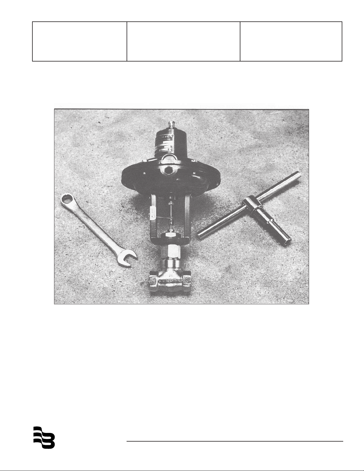
Series 9000
RESEARCH® CONTROL
Valves
Installation &
Operation Manual
BadgerMeter,Inc.
®
940467
1-02
Page 2

TABLE OF CONTENTS
Page
General .............................................................................................................................................. 1
Installation ......................................................................................................................................... 1
Disassembly and Reassembly ........................................................................................................... 1
Replacing Trim Sets ........................................................................................................................... 1
Installing Trim Sets ............................................................................................................................. 2
Lapping Sequence ............................................................................................................................. 3
Assembly ........................................................................................................................................... 3
Stroke Adjustment and Pressure Test ................................................................................................ 4
Packing, Chevron Ring ....................................................................................................................... 5
Braided Teflon and Graphoil Packing .................................................................................................. 5
Bellows .............................................................................................................................................. 7
General ............................................................................................................................................ 7
Removal of Assembly from Valve .................................................................................................... 7
Removing lnnervalve from Bellows Assembly & Seat from Body .................................................... 8
Installing Bellows Seal Assembly, Innervalve & Seat....................................................................... 8
Valve Positioners ............................................................................................................................... 9
General ............................................................................................................................................ 9
Integral Mounting ............................................................................................................................. 9
Range Springs ................................................................................................................................. 9
Top Loading, Air-to-Close ................................................................................................................. 9
Bottom Loading, Air-to-Open .......................................................................................................... 10
Adjusting Zero ............................................................................................................................... 10
Servicing........................................................................................................................................ 10
Terminology ...................................................................................................................................... 11
Notes ............................................................................................................................................... 12
Special Information .......................................................................................................................... 13
Page 3
General
The purpose of these instructions is to supply pertinent
information for installation of original equipment, repair,
adjustments, retrimming, repacking and other information necessary to achieve the best possible service
from Research Control Valves.
Research Control Valves are engineered, designed, and
manufactured with the end user in mind. Most parts are
interchangeable with any other like assembly. The inner
components (spare trims) are available in 39 different
flow coefficient (Cv) sizes and in many different materials compatible with most process conditions.
Installation
After inspecting the valve (or valves) and determining
that the valve (or valves) meets the specifications, install as follows:
1. Normal installation is directly into any 1/4", 1/2",
3/4", or 1” piping system with flow direction arrow on
body pointing downstream. This allows the stem packing to see the lowest pressure conditions after the
pressure drop occurs. It should be noted that chevron
ring stem packing is a dynamic seal that needs pressure to be energized.
2. Valves, especially plastic, should be bracket mounted
in high vibration areas or where they may be subjected
to damage from shock. If necessary, provide as required,
bypass, manual block valve, filters, etc. When installing valves that have the Low Flow “P” Series innervalves,
small micron filters should be used where process permits.
to hold unbalance created by higher pressure on actual
application. It should be noted that on air-to-close valves
with no pressure, the travel indicator will show over travel.
With 3 PSIG to actuator, the indicator will be very close
to the open position.
Disassembly and Reassembly
(Best done at instrument shop bench)
For the purpose of these instructions, consider the
topworks or actuator as a complete sub-assembly not
to be dismantled except for replacing diaphragms or
topworks packing. The only necessary topworks adjustment is made with the spring adjuster and/or the
zero adjustment on positioner-equipped valves (see
paragraph on Positioners). To position the stem, travel
in relation to the 3-15, 3-9, 9-15 PSIG etc. instrument
signal operating the valve.
Replacing Trim Sets
Installing innervalve trim sets is accomplished with the
body and bonnet subassembly separated from the
topworks using appropriate wrenches. (Tool kits are
available at a nominal cost for 1/4”, 1/2”, 3/4”, and 1”
valves.) To separate the body bonnet assembly from
the topworks on ATO valves, apply 6-9 PSIG instrument air to the operator, lifting innervalve off seat to
prevent damage to the valve seating surfaces. (Not
necessary for ATC valves.)
3. Connect instrument air supply to diaphragm case
using appropriate NPT fittings (1/8" NPT for 1/4" valves
and 1/4" NPT for 1/2", 3/4", and 1” valves) to the desired tubing size adaptor (normally 1/4” tube fittings).
All connections to standard positioners, Moore products or Badger
®
, are 1/4" NPT. (For positioner data, see
paragraph under Positioners.)
4. All standard production valves as shipped are adjusted and preset at the factory with 90 PSIG air piped
to the inlet port of the body. Air-to-open valves are adjusted to come off seat at approximately 3.25 PSIG
instrument signal and be fully opened at 15 PSIG. Airto-close valves are set to close when signal is at 14.75
PSIG and be fully open at 3 PSIG. Process conditions
may dictate additional adjustment of the spring adjuster
FIG. 1
1
Page 4
1 .With innervalve off seat, use two open-end wrenches
(1/4" for 1/4" valves and 3/8" for 1/2", 3/4", and 1”
valves), one holding the stem connector in position,
and with the other loosen the topworks stem nut above
travel pointer; remove travel pointer.
2. With valve body in vise (clamp on ends), loosen the
yoke to bonnet locknut (yoke locknut) with a slotted
end wrench (7/8" boxed end for 1/4" valves, 1-1/8" for
1/2", 3/4" and 1" valves), and unscrew completely.
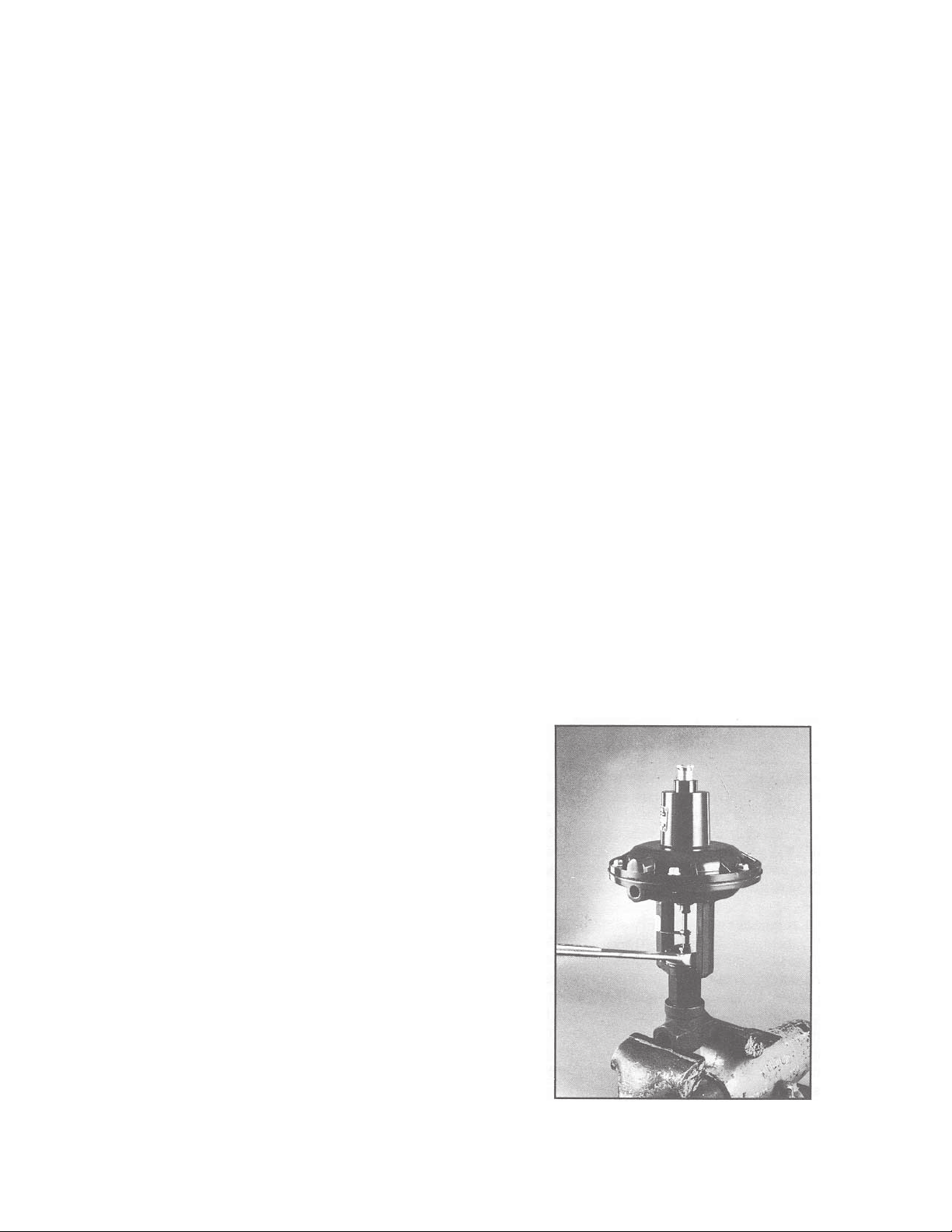
3. With the open-end wrench, turn the stem connector
counterclockwise (right hand threads), unscrewing from
the topworks stem completely. (Fig. 1)
4. Remove topworks from body bonnet assembly.
5. With the valve body in vise, loosen and unscrew
bonnet from body using open-end or crescent wrench.
Installing Trim Sets
(Matching pairs do not separate)
With all parts cleaned in an appropriate solvent, install
desired trim set in body bonnet assembly as follows:
FIG. 3
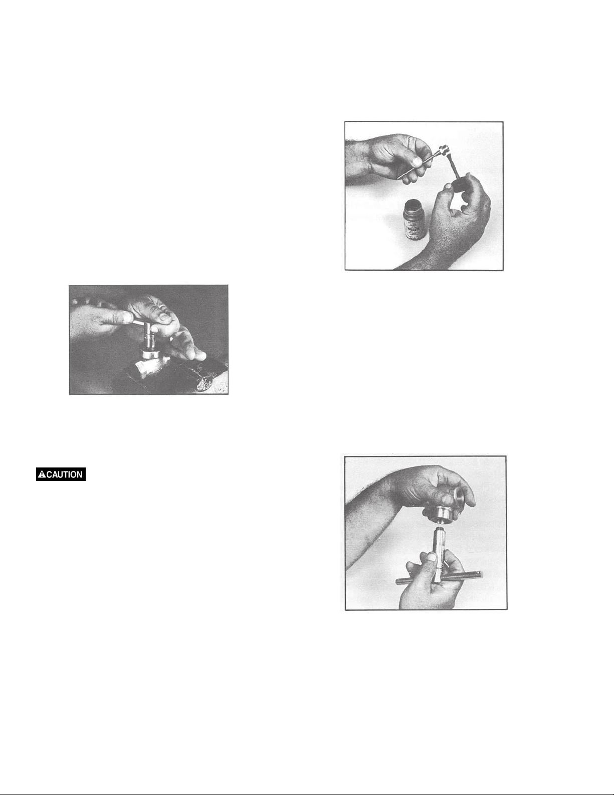
1. With trim as shown in Figure 3, apply a coating of
Neolube (graphite dry film lubricant), process permitting,
to the threads and seating surfaces of the seat. Air dry
for 30 seconds. Do not use any thread sealing
compounds containing metal particles. NOTE: New
replacement innervalves, come pre-coated with NeoLube
except those specially cleaned.
FIG. 2
6. Remove seat from body using a deep thin wall socket
and T-handle assembly (3/8" hexagon for 1/4" valves,
5/8" hexagon for 1/2", 3/4" hexagon for 3/4"valves, and
15/16" hexagon for 1” valves).
Some purchased long set sockets
(heavyduty) will not fit body cavity without turning
O.D. to fit past body threads.
(Fig. 2)
7. Most standard innervalves “K” through “P18” in 1/4"
valves and “F” through the “P” series trim in 1/2" valves
can be removed upward from the bonnet through the
packing, all others by removing stem connector and
withdrawing downward through the packing. When
removing the larger trims down through packing, it is
best to withdraw stems until threaded portion is in
contact with packing and then rotate stem and allow
the threads to screw through the packing area.
2. Remove seat from innervalve and place hex first into
the long set socket wrench and T-handle assembly.
NOTE: Tissue paper can be stuffed into the socket to
prevent seat from falling through.
FIG. 4
3. With body inverted in palm of hand as shown in
Figure 4, start seat threads into body, invert body and
tighten seat. Do not over-torque. Standard torque figures
using new parts at the factory are: 10/11 ft/pounds on
“P” trim seats, 8.5 ft/pounds on other 1/4" seats, 35 ft/
pounds on 1/2", 3/4" and 1” seats. It should be noted
that torque figures are applicable to new parts and may
not be the same for used parts. For longest service life,
on new or used parts, it’s best to use procedure detailed
in paragraph 4.
2
Page 5
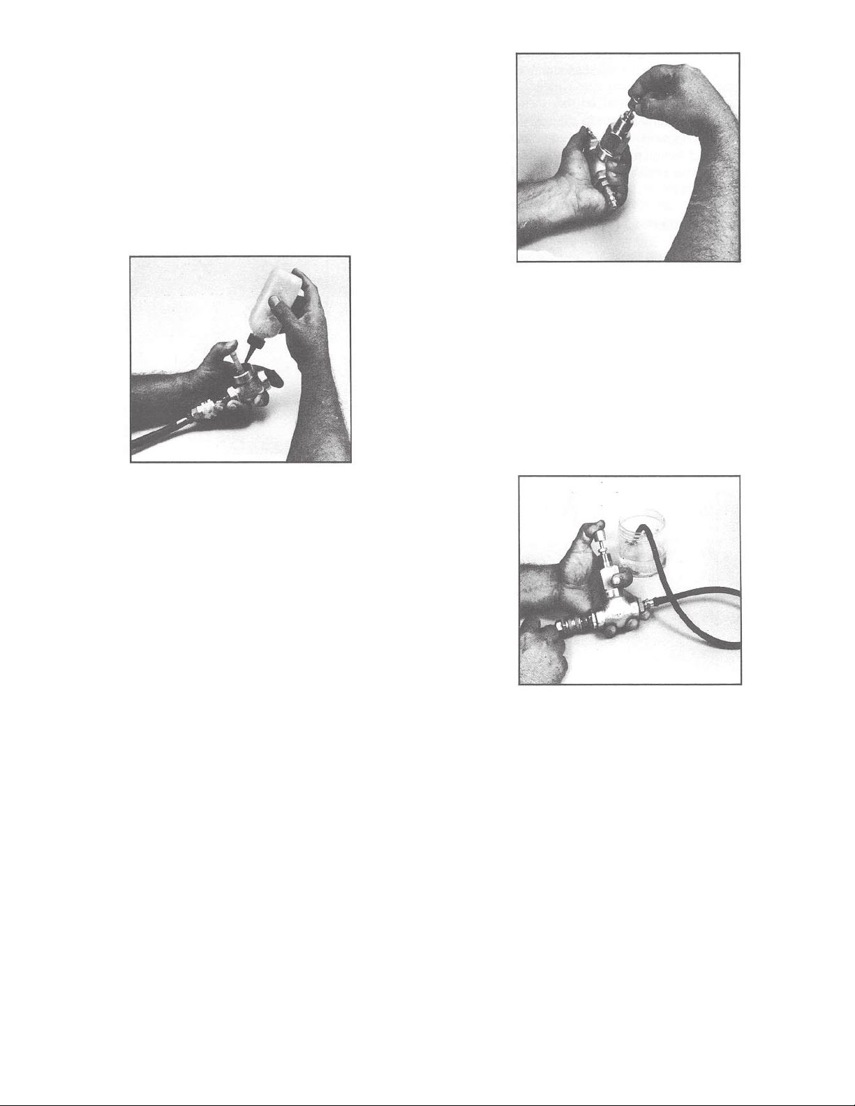
4. Torque seat firmly into body with the short T- handle
assembly. Check seat to body seal, by making body a
bubble chamber, using a pointed plastic plug in seat to
seal as shown in Figure 5 with downstream port plugged
and 50 psi air pressure upstream, check for leak. If
leak exists, re-torque seat and recheck until bubbletight seal is accomplished. On smaller letter or “P” series
trim sets, over-torquing seat in the body can reduce the
orifice size to where interference between innervalve
and seat can cause a premature mechanical failure
(galling) when stroking valve.
FIG. 6
clockwise, counterclockwise motion between the thumb
and forefinger, lifting the innervalve off seat and
repositioning periodically to achieve a uniform lap ring.
After each lapping operation, remove bonnet from body
and clean innervalve and seat from body. Clean seat by
submerging body in solvent and swabbing orifice with
wetted pipe cleaner and blow dry with air. After cleaning,
reassemble and check leak rate as shown in Figure 7.
Caution should be taken to not overlap.
FIG. 5
5. With body in vise, again clamping across ends of
body not sides of body, place body bonnet gasket in
place. (Process permitting, coat each side of gasket
with lubricant such as Dow Corning or Dupont Krytox
valve seal.) With the stem section of the trim set
installed in the bonnet, coat the bonnet threads (body
end) with lubricant.
6. Screw bonnet into body and tighten with open-end or
crescent wrench. Apply the proper torque to bonnet/
body joint as listed on the back side of individual
technical briefs.
7. Stroke innervalve manually to check for misalignment. Should misalignment exist, check straightness
of innervalve or packing. (See Packing Installation.)
NOTE: All replacement trim sets have been prelapped
at the factory. When installed per instructions, trims
should leak no more than 1/10 of one percent of
maximum flow for the given size, (ANSI Class III). If
necessary, with care, bubble-tight shutoff can normally
be achieved by lapping in seating surfaces with the
innervalve set installed in the body bonnet assembly
using lapping compound (white aluminum oxide 38-1000
grit) with the packing removed, using the packing glands
as the upper guide (brass lap bushing available at
factory). See Figure 6. Lapping should be done with a
FIG. 7
Lapping Sequence
Lap for about 30 seconds, clean and check leak rate;
repeat sequence until desired shutoff is achieved. If
after lapping three or four times leak still exists, check
the seating surfaces of both innervalve and seat for
excess nicks, scratches, or indication of galling if the
trim has previously been in service. Do not lap for
shutoff any of the “P” series trims.
Assembly
1. With body in vise, place topworks yoke on bonnet
with yoke locknut slipped over the stem connector and
down on bonnet threads (6-9 PSIG air on air-to-open
topworks).
2. With topworks in correct position relative to the
centerline of the body, tighten yoke locknut using a
boxed-end (slotted) wrench.
3
Page 6

3. Raise innervalve and screw the stem connector on
topworks stem until the two stems are butted together.
4. Install travel pointer between stem connector and
locknut on topworks stem. Hold stem connector in place
and tighten topworks stem nut against the travel pointer
positioned 1/32" to 1/16" away from travel scale.
Stroke Adjustment and Pressure Test
1. With valve completely assembled and with a manually
regulated supply (3-15 PSIG) to the topworks, adjust
with spring adjuster until valve stroke is corresponding
to the normal 3-15 PSIG instrument signal. To set this
precisely, pipe 90 PSIG air to the upstream port and
with rubber tubing piped from downstream port, bubble
check shutoff point. (Fig. 8)
2. Set air-to-open valves to open at 3-1/4" PSIG.
valve open. Using a plastic squeeze bottle filled with a
soapy water solution, flood each joint and inspect for
leaks. Check and tighten packing just until no leak is
visible. Do not over-tighten. (Fig. 9)
FIG. 8
3. Set air-to-close valves to close at 14-3/4" PSIG.
4. Nominal stem travel of 7/16" for 1/4" valves and
9/16" for 1/2", 3/4", and 1” valves is fixed in the topworks
spring rate for a 12 PSIG span. If valve has been set
with a high bench setting because of pressure, full travel
may not occur at 15 PSIG.
5. If necessary, reposition travel scale relative to stroke.
FIG. 9
7. Normal hysteresis (dead band) in valve stroke should
be no more than 1/4 PSIG instrument signal. This can
be checked by placing the thumb and forefinger on the
valve stem in contact with the packing gland and
regulating manually the 3-15 PSIG instrument signal
(gauge in line), visually watching gauge and feeling
movement. (Fig. 10)
6. Pressure test all seals with 90 PSIG air piped to the
upstream port, downstream port plugged with
FIG. 10
4
Page 7

Packing, Chevron Ring
1. Proceed with disassembly of body-bonnet assembly as in changing trims.
2. Remove the packing gland and all components from
within the cavity. If the Teflon packing follower has been
damaged due to over tightening and extruded into the
threads of the packing cavity, a standard screwdriver
can be driven into the teflon to unscrew the follower. ln
this case, the packing follower needs to be replaced.
3. Clean and inspect cavity and parts for damage.
4. Place packing adaptor in the cavity making sure the
flat side is down and in place.
5. Place the first ring into the cavity at a 90 degree
angle to its seated position. When the ring is at the
bottom of the cavity, tip it over with the cup side down
using a small plastic or wooden probe. Continue this
procedure with the two additional rings. This method
prevents the threads of the cavity from damaging the
lips of the rings.
6. Place the packing follower on top of the rings, making
sure the inverted “V” is down. (The arrangement for
reversed Cv ring vacuum packing requires special parts.)
7. Replace the packing gland. Tighten until contact is
made with the packing follower.
8. If the plug portion of the trim is machined integral on
the stem, the stem connector should be tightened onto
the stem before insertion into the bonnet and may be
inserted through the packing from the top of the bonnet.
If the plug portion of the trim is screwed onto the stem,
the stem should be placed through the packing from
the bottom of the bonnet by gently screwing the stem
threads through the packing. The stem connector can
then be tightened onto the stem.
psi). If packing leaks, tighten gland just until leak stops.
Excess torque can damage Teflon components. Once
this procedure is complete, the valve can be tested at
higher pressures.
CAUTION: Do not tighten gland more than is necessary
to stop leaks.
NOTE: On valves supplied prior to October 1993, the
packing follower on all valves was virgin Teflon and
packing adaptor was the same metal material as valve.
To improve on the total packing function in regard to
sealing and replacement, both the follower and adaptor
materials have been changed to now available, Teflon
PFA. This denser Teflon material allows the guide
diameter to be closer for better alignment and solves
the cold flow problem of the original virgin Teflon follower.
Braided Teflon and Graphoil
The original packing for Research Control Valves was
braided Teflon which used a smaller gland nut. After
molded chevron rings became available and for a period
of time, there was a difference between the bonnet
packing cavity, depending on type of packing used. The
components parts were not interchangeable until the
current design was introduced in 1972, standard 1981,
using a common cavity for all types packing.
1. Braided Teflon is available and used in current packing
cavity by putting in a dummy stem to fit the packing
over as shown in Figure 11. Fill the cavity
9. Retract the stem sufficiently to keep the trim from
seating and screw the bonnet into the body. Be sure to
install gasket.
10. Apply the proper torque to bonnet/body joint as listed
on the back side of individual technical briefs under
pressure/temperature ratings.
11. Proceed with assembly and adjustments per Page
3.
12. Test packing by tightening gland 1/4 turn past
fingertight. Do initial test with low pressure (80 to 100
FIG. 11
with sock or rope type packing, tamping into the cavity
with a packing tool or piece of appropriate size copper
tubing as shown in Figure 12, until cavity is full with a
couple threads showing. Screw gland in and tighten to
compress packing.
5
Page 8

FIG. 12
FIG. 13
Remove gland and blow or pick out any small pieces
that may be in the threads. (Fig. 13) Replace gland finger
tight and remove dummy stem Figure 14 and replace
with new innervalve and stem. Tighten packing gland
and test seal at final assembly the same as with chevron
ring packing.
FIG. 14
2. Graphoil Packing
Depending on the application, graphoil packing is
available in preformed rings to fit standard packing
cavities for all Research Control Valves. When a process
must run hot to prevent material from solidifying or for
other purposes where finned bonnets are used to
dissipate heat to protect the packing are not applicable,
graphoil may be the solution. If the application is quick
opening (on-off) and graphoil packing is used, the
standard actuator will work with higher operating pressure.
If application is to control, a positioner should be used
to overcome additional drag, or hysteresis, created by
graphoil making stem seal, especially on high pressure
gases.
6
Page 9

Bellows
General
On applications involving toxic gases, radioactive
materials and others where the primary seal at the valve
stem is critical, a metal bellows stem seal can be used
to preclude leakage as long as the integrity of the
bellows remains intact. Extreme care should be
exercised in removing and/or installing the Bellows Seal
Assembly to preclude damage. The metal thickness of
the low pressure bellows is only 0.005” to 0.007” thick,
and excess torsion will twist and deform the convolutions,
damaging the assembly.
FIG. 15
FIG. 17
FIG. 16
FIG. 18
Removal of Assembly from Valve
1. Remove the valve from the process line and hold
valve in a bench vise clamped on the body ends.
2. On air-to-open valves apply air pressure to diaphragm
to raise innervalve off seat. (Not necessary for air-to close valves).
7
Page 10

3. Loosen stem connector locknut above travel indicator.
4. Loosen yoke nut holding topworks to bonnet.
NOTE: If the above procedure is being done because of
bellows failure, it is not necessary to be concerned
about damage to the bellows.
5. Rotate entire topworks counterclockwise; top-works
stem will unscrew from stem connector.
CAUTION - Unscrew straight up or stem could be bent.
6. Finish unscrewing yoke nut and lift off topworks.
7. Loosen and unscrew bonnet assembly from body.
(Fig. 16)
8. Loosen and unscrew bonnet cap and bellows
assembly from bonnet. (Fig. 17)
9. Grasp bonnet stem located immediately under
connector with sharp nose pliers and remove connector
without allowing stem to turn.
10. Remove the bellows from the bonnet cap. At times
it is necessary to cut and fish out the Teflon bellows
gasket in order to free up the bellows assembly for
removal.
Removing lnnervalve from Bellows Assembly and
Seat from Body
1. Hold stem of bellows in a lathe collet or suitable
holding device (1/8" for 1/4" valves or 3/16" for 1/2",
3/4", and 1” valves) and gently unscrew innervalve
counterclockwise using a small end wrench fitting the
flats on the innervalve. Avoid any side motion or bending.
If the bellows stem threads unscrews before the
innervalve unscrews, make a strap wrench by cutting a
strip of 80 grit emery paper the width of the bellows
length and roll about three revolutions clockwise around
the bellows assembly with the coarse side against the
bellows. Grasp the emery paper by hand and with the
wrench on the innervalve flats, remove the innervalve
from the bellows. Normally this procedure prevents
damaging the bellows because the emery paper wrapped
around the bellows gives it more support transferring
the twisting forces to where the bellows is welded to
the lower end plate.
2. Do not try to remove stem from bellows assembly.
3. Do not grasp the bellows in any manner other than
above nor allow it to twist.
4. Unscrew seat from body with a long set socket
wrench.
Installing Bellows Seal Assembly, lnnervalve and
Seat
Generally the foregoing steps are the reverse of
disassembly, but best results will be experienced by
processing in the following sequence:
1. Screw innervalve into bellows assembly only hand
tight.
2. If the secondary packing in bonnet cap has not been
damaged, proceed; otherwise, remove old packing but
do not replace until later.
3. Place bellows-bonnet gasket carefully over bellows
to flange.
4. Insert stem into bonnet cap, carefully turning in a
clockwise direction until flange is seated all the way
into bonnet cap.
5. Be sure gasket is home and not damaged.
6. With bellows upward, carefully screw bonnet into
bonnet cap by hand until it is seated.
7. Holding bonnet in a vise, screw bonnet cap home
firmly with a wrench.
8. At this point install new secondary packing if
necessary, tightening gland firmly by finger tight as with
a standard packed valve. (See paragraph on packing.)
9. Remove from vise and hand-install connector by hand.
10. With small wrenches on connector and flats on the
innervalve, tighten firmly but prevent using any side
motion.
11. With body held in a vise as instructed, screw the
bonnet, bellows seal and innervalve assembly into the
body.
12. When body bonnet assembly is complete, the
innervalve should be off seat with the bellows in its free
state and should move approximately 1/8" when pushed
down before touching seat.
8
Page 11

13. CAUTION - With valves having “P” trims, be sure
the plug enters the seat before starting the bonnet
threads into the body.
14. Assemble the topworks to the body-bonnet assembly
in the exact reverse order from dismantiling. On air-to
open topworks remember to have air on the diaphragm,
rotating the topworks until the topworks and bellows
stem butts together in the middle of the connector. Use
Valve Positioners
General
Badger’s valve positioners use the full force of the air
supply pressure to drive the diaphragm or piston of the
pneumatic actuator to a position corresponding to the
pneumatic instrument signal output from a controller
(pressure, temperature, flow, etc.) and hold that position,
regardless of the forces which tend to change valve
position.
two wrenches to tighten travel indicator lock nut to
preclude twisting the bellows. If the topworks is not in
the correct position with the stems butted together in
the middle of the connector, rotate the topworks
counterclockwise to the correct position before locking
down the stem locknut. Do not rotate more than 90°
15. See stroke adjustment and pressure test.
Like all valve positioners, Badger’s have a feedback
circuit which measures position of the actuator’s
diaphragm or piston. The built-in valve positioner
supplies or vents air in response to the control-instrument
signal stroking the valve to the required position.
Integral Mounting
Badger’s compact valve positioners incorporate a single
axis force-balance principal of operation to insure
accurate and stable positioning of Research Control
Valves. The positioners become an integral part of the
valve actuator. In all cases, including bottom loading
applications, the built-in valve positioner is mounted
directly on the topworks with no external piping or other
exposed mechanisms.
Range Springs
The position of the diaphragm or piston in the valve
actuator is sensed by the amount of compressive force
exerted by the range spring on the valve actuator
diaphragm assembly. Standard strokes are 7/16" and
9/16". Standard signal ranges are 3-15, 3-9, 9-15, and
6-30 PSIG. Consult the factory for other ranges.
Top Loading, Air-to-Close
Air pressure from the control instrument is exerted
between the two lower diaphragms. Because of the
difference in the two diaphragm areas, the resultant force
is exerted in an upward direction. In balance condition,
the pneumatic force on the diaphragm plus
9
Page 12

the upward force exerted by the range spring is balanced
by the downward force of the zero adjustment spring. In
balance condition, positioner vents to atmosphere.
When control-instrument pressure increases, the
diaphragm assembly will move upward closing the
exhaust port and opening the pilot valve allowing supply
air to pass directly to the actuator diaphragm. The supply
air will drive the actuator downward. As the actuator
moves down, the range spring relaxes until its force
decreases enough to offset the increase in controlinstrument pressure, allowing the pilot valve to close
and exhaust to open. On air-to-close valves with
positioners, the supply pressure should be sufficient
for function, but never excessive. For function the
positioner supply pressure needs to be a minimum of 3
PSIG above instrument signal. Excessive supply
pressure can result in damage to trims when the
innervalve touches the seat and the signal continues
down. The positioner sees this as resistance and reacts,
causing the full supply pressure to be applied to the
main diaphragm in the actuator.
ATO valves with type BLRA or Moore 73B positioners,
zero adjustment is made with 3 psi instrument air to the
positioner, turning zero adjustment screw until valve
seats at 3 psi. Full travel within tolerances governed by
the range spring should occur on ATO or ATC valves
using the standard 3-15, 3-9, 9-15, etc. instrument signal.
NOTE: Factory zero adjustments are made on Research
Control Valves with positioners, using 90 PSIG air
pressure piped to the upstream valve port, connecting
a Tygon or rubber tubing to the downstream port and
immersing the end in a water filled container to detect
any leakage across the seat during zero adjustment.
Servicing
Badger’s valve positioners must be isolated from the
system before service or removal can be accomplished.
(Recommended procedure is to move complete valve
with positioner to instrument repair bench where
necessary tools and manual set air regulators are
available.)
Bottom Loading, Air-to-Open
Air pressure from control instrument is inserted between
the dual upper diaphragms and the center diaphragm.
Because of the difference in the two diaphragm areas,
the resultant force is exerted in a downward direction.
In balance condition, the pneumatic force on the
diaphragm, plus the downward force exerted by the zero
adjustment spring, is balanced by the upward force of
the range spring. In balance condition, positioner vents
to atmosphere.
When control-instrument pressure increases, the
diaphragm assembly will move downward allowing the
spool valve to close the exhaust port and allow the
supply air to pass through interior porting to the bottom
side of the diaphragm or piston in the actuator. The
supply air will drive the actuator upward. As the actuator
moves up, the range spring will compress until its force
increases enough to offset the increase in controlinstrument pressure causing the spool valve to move,
shutting off supply air to the actuator and opening
exhaust.
Adjusting Zero
To clean pilot or spool valve, remove brass hex head
sealing screw under top cap and with small sharp nose
pliers, tweezers or other device, remove and clean pilot
or spool valve and replace. On air-to-close TLDA and
Moore 73N positioners, the pilot is a one piece unit that
seldom fails due to dirty air or material such as Teflon
tape getting into the pilot and causing malfunction. On
air-to-open BLRA and Moore 73B positioners, the
functional clearances around the spool valve is very
close and more likely to fail due to dirty air or Teflon
tape. Clearance is a function of bleed and must be close
as possible, but large enough to function. To replace
the diaphragm assembly, it is necessary to unscrew
the six screws holding the positioner to the adaptor and
remove the positioner assemble. Invert positioner and
remove the two assembly screws in the bottom ring.
When assembling the positioner diaphragm assembly
to the main housing, make sure to align index grooves.
Positioners must be correctly assembled in order to
function. Individual sub-assemblies such as the
diaphragm assembly should be replaced as one unit.
For ATC valves with type TLDA or Moore 73N12F
positioners, zero adjustment is made with 15 psi
instrument air (for 12 psi span) to the positioner, turning
zero adjustment screw until valve seats at 15 psi. For
10
Page 13

TERMINOLOGY
PCV -
Pressure Control Valve
LCV -
Level Control Valve
TCV -
Temperature Control Valve
FCV -
Flow Control Valve
Topworks (Actuator) -
Positioner -
ATO -
ATC -
F/O -
N/O -
F/C -
N/C -
Body Bonnet Assy -
Instrument added or attached to topworks for more precise control
Air to Open. Increasing air signal opens valve
Air to Close. Increasing air signal closes valve
(Fail Open) Valve opens on air failure
(Normally Open) Valve opens on air failure
(Fail Close) Valve closes on air failure
(Normally Close) Valve closes on air failure
The assembly that provides force
That assembly consisting of body, bonnet, gasket, innervalve, stem, seat, packing,
gland and yoke nut
Trim Set -
=% -
Lin. -
Q.O. -
P1 -
P2 -
HP -
The interchangeable components in a set consisting of innervalve, stem and seat
Equal Percentage. Lift versus flow characteristic
Linear lift versus flow characteristics
Opening - ON-OFF service
lnlet pressure to valve
Downstream pressure from valve
Delta P - Pressure drop across valve
Cv -
Flow Coefficient - Water flow at 1 PSI pressure drop
Chevron Rings -
Braid Tef. -
Packing, molded V-rings (normally 3 per set)
Packing, rope-type braided Teflon with Teflon suspensoid lubricant
11
Page 14

Notes
12
Page 15

Special Information
Use this page for recording special operator information not included in the preceding (i.e., internal and supplier phone
numbers, addreses, etc.)
13
Page 16

Please see our website at
www.badgermeter.com
for specific contacts.
Copyright © Badger Meter, Inc. 2002. All rights reserved, all data subject to change without notice.
Due to continuous research, product improvements and enhancements,
Badger Meter reserves the right to change product or system specifications
without notice, except to the extent an outstanding bid obligation exists.
BadgerMeter,Inc.
6116 E. 15th Street, Tulsa, Oklahoma 74112
(918) 836-8411 / Fax: (918) 832-9962
®
www.badgermeter.com
 Loading...