

Page 1

Recordall® Transmitter Register (RTR®)
Remote Electronic Display (RED)
SUGGESTED TOOLS
• Electric Drill
• 3/16” Carbide Tip Masonry Drills
• Screw Driver
• Wire Stripper
• T-10 Stapler with Cable Attachment
• 59983-001 Crimping Tool
• 59989-001 Cable Stripper
• 59991-001 Wire Cutting Pliers
MISCELLANEOUS PARTS PROVIDED
• Two Wire Connectors
• Seal Screw
• Strain Relief Ring
• Units of Measure Label
REQUIRED MATERIAL
• Non-Corrosive Staples
• Caulking Compound
• Masonry Fasteners
• Non-Corrosive Screws
• 62440-001 Belden 8451 Wire if proper length not supplied with
RTR®
IDENTIFICATION
The Model RED (Remote Electronic Display) remote reading
registers are designed for use with all Badger® Recordall® Disc,
Turbo, Compound and Fire Series meters equipped with RTR®
registers, plus the Badger Magnetoflow® meter.
REGISTER INSTALLATION
While the RED electronics and battery are environmentally
sealed and suitable for outdoor installation, the wire terminals
are not sealed from moisture. The unit, therefore, should not
be installed in locations below grade level or in a submersible
environment.
1. Remove register cover.
2. Using the register base as a template, locate and mark
mounting holes on outside wall of building. For best results
the RED should be located at eye level in an easily accessible
location.
3. Secure register base to wall using the mounting dimensions
in the drawing below to drill the locating holes.
NOTE: Avoid mounting register on loose siding of any type
since this will only lead to wire breakage or other potential
problems. (Register mounting hardware is supplied by the
customer).
4. Drill a 3/16” wire entry hole at a suitable location in the build-
ing wall.
5. Run the wire from the meter-mounted RTR through the hole
in the wall to the Remote Electronic Display register.
6. Cut the wire to proper length at the register, allowing suffi-
cient wire for connection to the register. Maximum wire length
between the RTR and the RED register is 3000 feet using Belden
8451 wire.
NOTE: Wire access to the Remote Electronic Display register is
through a bottom access port. Allow sufficient wire to form a
small U-shaped loop where the wire enters the building. The
loop eliminates the possibility of rainwater running down the
wire into the building.
RED-I-01 (10-10)
64573-002 Rev. 4
Installation Data
Page 2

7. Place the strain relief ring around the RTR lead wire and
secure.
8. Carefully remove about 1-1/2” of the outer sheath of the RTR
lead wire, up to the strain relief ring; avoid cutting the lead wires
or the insulation of the wires. Strip about 1/2” of the insulation
from both RTR lead wires.
9. Remove any temporary protective material from the register
base using the two register terminal screws. Do not tighten
down the screws yet.
10. Connect the RTR cable conductors to the RED wires using
the wire connectors provided in the installation kit. Crimp
the cables completely using a parallel jaw crimper such as the
Badger Meter P/N 59983-001. Polarity must be observed when
connecting the RTR to the RED wires: red (+) to red, black (-) to
black. Make sure to place the wire connector and strain relief in
the rextangular recess of the base.
11. Attach register cover to register base with the Seal screw.
The Seal screw is designed to discourage and identify tamper-
ing.
12. Secure the entire length of wire run from the RTR to the RED
to complete a neat installation.
13. The complete system (meter, RTR, RED, and wire) should be
performance tested to insure proper installation. Refer to perfor-
mance check section of this bulletin for procedures.
Wait after each tap until one of the small comma symbols (dots)
near the top left corner of each display digit lights up acknowl-
edging your tap, then tap again. Keep tapping until the number
of dots above the digits corresponds to the number of taps in
the current password digit. For example, if 3 password taps have
been received, then 3 digits will have a small dot lit above them.
The following shows 3 dots above the digits, so 3 of 8 password
taps have been acknowledged so far:
‘ ‘7 ‘6 5 4 3 2 1
4. After all the taps have been acknowledged for the first pass-
word digit, wait a few seconds for the dots to disappear, then
start tapping in the next digit. Repeat until all 4 of the password
digits stated above have been tapped in. The following shows
correct entry of all 4 password digits:
8 acknowledged taps:
‘ ‘7 ‘6 ‘5 ‘4 ‘3 ‘2 ‘1
Wait for dots to disappear:
7 6 5 4 3 2 1
3 acknowledged taps:
PROGRAMMING INSTRUCTIONS
Since the Badger RTR is an incremental encoder, RED must be
programmed to match the meter reading upon installation.
From that point forward the incremental pulses from the meter
should keep the RED in sync with it. Programming the RED
clears any existing “tamper” error flag.
1. After connecting the RED to the RTR, tap the circular gold disk
on the front of the RED display.
2. If the message “PROGRMNG REQUIRED” appears, the RED has
never been programmed since power was applied, or has gone
through reset. The current meter reading must be programmed.
3. To enter PROGRAMMING MODE, tap the display to turn it
on, then when it is displaying either a meter reading or the
“PROGRMNG REQUIRED” message, tap the following password
into the display:
8 taps
3 taps
7 taps
2 taps
‘ ‘7 ‘6 5 4 3 2 1
Wait for dots to disappear:
7 6 5 4 3 2 1
7 acknowledged taps:
‘ ‘7 ‘6 ‘5 ‘4 ‘3 ‘2 1
Wait for dots to disappear:
7 6 5 4 3 2 1
2 acknowledged taps:
‘ ‘7 6 5 4 3 2 1
5. After all of the password digits have been tapped in success-
fully, the display will show the message “PROGRAM MODE”. If the
meter is not connected properly a diagnostic message is issued
at this point, otherwise proceed as follows with programming of
the digits.
Page 3
6. A digit will appear near the left side. This is the first (left-most)
digit of the meter to be programmed in (this will be 2nd digit
from left on display, since far left digit is reserved for “E” tamper
error character). Tap to increment the digit until it equals the
left-most odometer digit of the meter (if the left-most meter
digit is already correct no taps need to be entered). To correct a
mistake keep tapping until the digit rolls over from 9 back to 0
and then counts upward again to the desired digit.
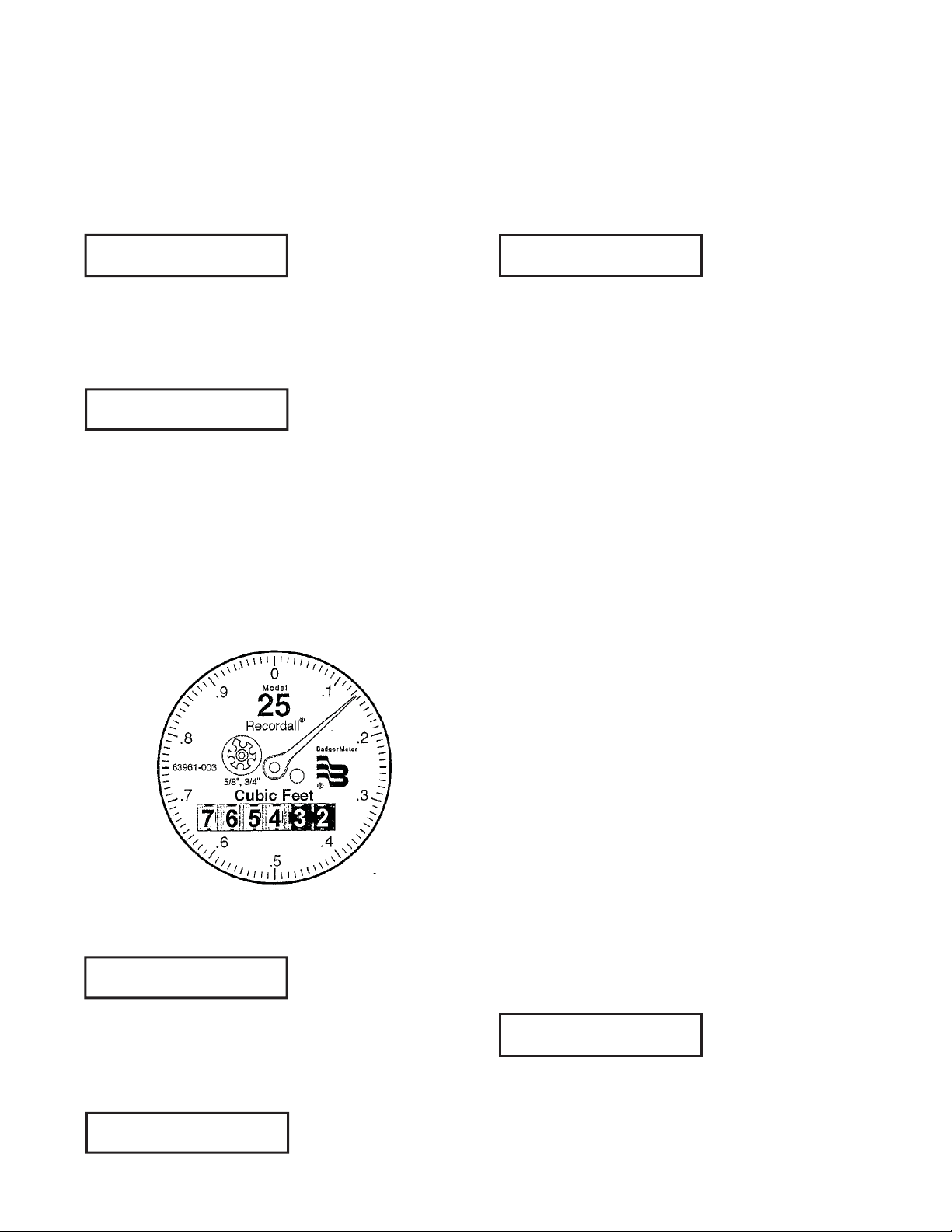
10. Tap until the decimal point is to the right of the least
significant billing digit. For example, for the meter displayed
above, if the utility wishes to bill in units of hundreds of cubic
feet of water (the first 4 digits only, which happen to be white),
the decimal point should be moved to the right of the 4th digit
from the left, which is between the numbers “4” and “3” in the
example above. After tapping the decimal point into position
the RED display looks like:
0
7. After 4 seconds of no tapping, the next digit to the right will
illuminate. Tap until this digit matches the corresponding meter
digit (second from left). Wait at least 4 seconds to move to the
next digit.
7 0
8. Continue tapping in digits to match the meter’s movable
odometer digits. When reaching the 7th digit from the left (the
right-most digit) on the RED display, tap to make its value match
the sweep hand of the meter. The value of the far right digit
should be the next lower major division of the sweep hand (not
rounded up, but truncated down). The major divisions of the
round sweep dial are numbered 0 through 9, possibly multiplied
or divided by a power of 10. In the example below the sweep
hand is read as “1:”
7 6 5 4. 3 2 1
The billing digits clearly read “7654” since they are to the left of
the decimal point.
11. Wait until the display blanks.
12. Run enough water through the meter to advance the sweep
hand to just past the next labelled digit. Tap the circular disk to
display the meter reading. Check to make certain that the read-
ing is correct. The display will dynamically update the reading
until the display turns off (after 20 sec).
NOTE: The RED software version displays briefly before the
display turns off.
READING THE METER
1.Tap the circular disk on the front of the display.
2. Write down the digits shown which are to the left of the deci-
mal point. This is the meter reading for billing purposes.
The display will be immediately updated if the meter reading
changes while the display is active, so it is possible to watch the
digits change as water is used.
Digits programmed into RED display corresponding to above
meter reading:
7 6 5 4 3 2 1
9. Next, a decimal point will show up at the far right of the dis-
play to the right of the right most digit. Tap the display to move
the decimal point 1 digit to the left for each tap (wait until the
decimal point moves before tapping again).
7 6 5 4 3 2 1.
After the reading has been displayed for 20 seconds, the soft-
ware version is displayed for 2 seconds, then the display turns
off. The reading is re-displayed if the housing is tapped either
during the RED version display or after the display turns off.
Don’t tap during the meter reading display unless you wish to
enter the programming password and reprogram the value.
If the cable between RED and the meter has been disconnected
or shorted since last programmed, an “E” will appear at the far
left side of the reading, indicating that the reading may be erro-
neous. This tamper error flag can only be cleared by reprogram-
ming the RED as described in “Installing the RED” above. The
following example shows the TAMPER error indicator turned on:
E 7 6 5 4. 3 2 1
Page 4

RED USER ERROR MESSAGES
PERFORMANCE CHECK
The display will indicate one of the following messages if an er-
ror is encountered during programming of a meter reading:
MESSAGE DESCRIPTIONS
One or both wires are discon-
CHECK WIRING,
OPEN CIRCUIT
CHECK WIRING,
REVERSE POLAR-
ITY
CHECK WIRING,
SHORT CIRCUIT
INTERNAL
(SOMETHING)
An “E” (for “Error”) will display to the left of the meter reading if
tampering has occurred by either disconnecting or short-circuit-
ing the two wires between the RED and the meter register. This
“E” is displayed until the RED is reprogrammed.
nected. Check wiring connec-
tions between RED and the
register
The red and black wires ap-
pear to have been reversed.
Check for proper polarity of
connection.
The red and black wires ap-
pear to be shorted together
somewhere.
An internal error has oc-
curred. Contact the manu-
facturer.
The RED installation should be checked for proper operation by
using one of the following methods:
NOTE: If meter is installed backwards, the RTR transmitter will
not send a signal to the RED remote register. To insure meter is
installed correctly, flow arrow on meter should point in direction
of water flow.
• Meter Test — Run an adequate amount of water through the
meter and observe that the RED register records correctly.
• Ohm Meter Test — Once the complete system is wired, it is
important to check for continuity using an ohm meter. Connect
the ohm meter across the RED terminals. An “open” should be
indicated. When operating the RTR the ohm meter should show
a momentary voltage deflection toward zero when the RTR
sends a signal.
THIS DEVICE COMPLIES WITH PART 15 OF FCC RULES. OPERA-
TION OF THIS DEVICE IS SUBJECT TO THE FOLLOWING TWO
CONDITIONS: (1) THIS DEVICE MAY NOT CAUSE HARMFUL INTER-
FERENCE. (2) THIS DEVICE MUST ACCEPT ANY INTERFERENCE
RECEIVED, INCLUDING INTERFERENCE THAT MAY CAUSE UNDE-
SIRED OPERATION.
ADDITIONAL INSTALLATION TIPS
• Never short yourself on wire. It is better to have a little excess
than to have to go back and rewire.
• If the RED is replacing an existing Read-o-Matic® display, do not
use the existing interface wiring. You will need to replace it with
new RTR wire (Belden 8451).
• If after wiring, unit does not operate, check for bare wires touching each other.
• When stapling wire, be careful not to pierce covering. This could
short out unit.
• When installing the unit on buildings having a stone or masonry
exterior, the use of masonry cleats and fasteners is required. After
determining register location, use a 3/16” carbide-tip masonry
bit and drill two register mounting holes. Insert masonry cleats
and attach register with round head screws.
Page 5

RED MULTIPLIERS FOR VARIOUS UNITS OF MEASURE AND METER SIZES
NOTE: Always verify the Test Circle (the value of the full 360-degree sweep of the register hand) for your particular RTR before using
these tables.
Gallons Cubic Feet
RECORDALL Disc Meters
Meter Size
M25
M35 3/4” Gallons 10 1 M35 3/4” Cubic Feet 0.1 1
M40 1” Gallons 10 1 M40 1” Cubic Feet 0.1 1
M70 1” Gallons 10 1 M70 1” Cubic Feet 0.1 1
M70 1-1/2” Gallons 100 10 M70 1-1/2” Cubic Feet 1 10
M120 1-1/2” Gallons 100 10 M120 1-1/2” Cubic Feet 1 10
M170 2” Gallons 100 10 M170 2” Cubic Feet 1 10
M180 2” Gallons 100 10 M180 2” Cubic Feet 1 10
5/8”,
3/4”
Unit of
Measure
Gallons 10 1 M25
RTR Test
Circle (gal)
RTR Resolution
(gal)
Meter Size
5/8”,
3/4”
Unit of
Measure
Cubic Feet 0.1 1
RTR Test
Circle
RTR Reso-
lution
RECORDALL Turbo Series Meters
Meter Size
T160 1-1/2” Gallons 1000 100 T160 1-1/2” Cubic Feet 100 10
T200 2” Gallons 1000 100 T200 2” Cubic Feet 100 10
T450 3” Gallons 1000 100 T450 3” Cubic Feet 100 10
T1000 4” Gallons 1000 100 T1000 4” Cubic Feet 100 10
T2000 6” Gallons 1000 100 T2000 6” Cubic Feet 100 10
T3500 8” Gallons 1000 100 T3500 8” Cubic Feet 100 10
T5500 10” Gallons 1000 100 T5500 10” Cubic Feet 100 1 0
T6200 12” Gallons 10000 1000 T6200 12” Cubic Feet 1000 100
T6600 16” Gallons 10000 1000 T6600 16” Cubic Feet 10000 100
T10000 20” Gallons 10000 1000 T10000 20” Cubic Feet 1000 1000
Unit of
Measure
RTR Test
Circle (gal)
RTR Resolu-
tion (gal)
Meter Size
Unit of
Measure
RTR Test
Circle
RTR Resolu-
tion
RECORDALL Turbo II Meters
Meter Size
T200 2” Gallons 1000 100 T200 2” Cubic Feet 100 10
T450 3” Gallons 1000 100 T450 3” Cubic Feet 100 10
T1000 4” Gallons 1000 100 T1000 4” Cubic Feet 100 10
T2000 6” Gallons 1000 100 T2000 6” Cubic Feet 100 10
T3500 8” Gallons 1000 100 T3500 8” Cubic Feet 100 10
T5500 10” Gallons 1000 100 T5500 10” Cubic Feet 100 10
T6200 12” Gallons 10000 1000 T6200 12” Cubic Feet 1000 100
T6600 16” Gallons 10000 1000 T6600 16” Cubic Feet 1000 100
T10000 20” Gallons 10000 1000 T10000 20” Cubic Feet 1000 100
Unit of
Measure
RTR Test
Circle (gal)
RTR Resolu-
tion (gal)
Meter Size
Unit of
Measure
RTR Test
Circle (gal)
RTR Resolu-
tion (gal)
Page 6

Cubic Meters
RECORDALL Disc Meters
Meter Size
M25
M35 3/4” Cubic Meter 0.1 0.01
M40 1” Cubic Meter 0.1 0.01
M70 1” Cubic Meter 0.1 0.01
M70 1-1/2” Cubic Meter 1 0.1
M120 1-1/2” Cubic Meter 1 0.1
M170 2” Cubic Meter 1 0.0
M180 2” Cubic Meter 1 0.1
5/8”,
3/4”
Unit of
Measure
Cubic Meter 0.1 0.01
RTR Test
Circle (gal)
RTR Resolution
RECORDALL Turbo Series Meters
Meter Size
T160 1-1/2” Cubic Feet 1 0.1
T200 2” Cubic Feet 1 0.1
T450 3” Cubic Feet 1 0.1
T1000 4” Cubic Feet 1 0.1
T2000 6” Cubic Feet 10 1
T3500 8” Cubic Feet 10 1
T5500 10” Cubic Feet 10 1
T6200 12” Cubic Feet 10 1
T6600 16” Cubic Feet 10 10
T10000 20” Cubic Feet 100 10
Unit of
Measure
RTR Test
Circle
RTR Resolution
RECORDALL Turbo II Meters
Meter Size
T200 2” Cubic Feet 1 0.1
T450 3” Cubic Feet 1 0.1
T1000 4” Cubic Feet 1 0.1
T2000 6” Cubic Feet 10 1
T3500 8” Cubic Feet 10 1
T5500 10” Cubic Feet 100 10
T6200 12” Cubic Feet 100 10
T6600 16” Cubic Feet 10 1
T10000 20” Cubic Feet 10 1
Unit of
Measure
RTR Test
Circle (gal)
RTR Resolution
Page 7

Intentional Blank Page
Page 8

Recordall® and RTR® are registered trademarks of Badger Meter, Inc.
Copyright 2010, Badger Meter, Inc. All rights reserved.
Due to continuous research, product improvements
and enhancements, Badger Meter reserves the right
to change product or system speci cations without
notice, except to the extent an outstanding contractual
obligation exists.
Badger Meter | P.O. Box 245036, Milwaukee, Wisconsin 53224-9536
800-876-3837 | infocentral@badgermeter.com | www.badgermeter.com
 Loading...