

Page 1
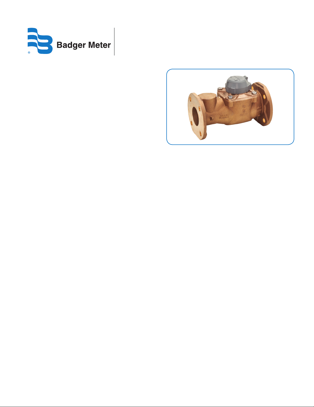
Recordall® Turbo Series Meters
Models 160 (1-1/2 in.), 200 (2 in.), 450 (3 in.), 1000 (4 in.),
2000 (6 in.), 3500 (8 in.), 5500 (10 in.) and 6200 (12 in.)
NSF/ANSI Standards 61 and 372 Certied
DESCRIPTION
Recordall Turbo Series meters meet or exceed the most recent
revision of AWWA Standard C701 Class II Standards and are
available in a lead-free bronze alloy for sizes 1-1/2 in. through 10 in.
and cast iron for 12 in. meters. Turbo Series meters comply with the
lead-free provisions of the Safe Drinking Water Act. Sizes
1-1/2 in. through 10 in. meters are also certified to NSF/ANSI
Standards 61 and 372 (Trade Designation: Turbo Series LL-NS)
and carry the NSF-61 mark on the housing. All components of the
lead-free alloy meter (housing, measuring element, seals and so on)
comprise the certified system.
Models 160 through 6200 are designed for 1-1/2 in. through
12 in. applications. These meters feature:
• Direct coupled turbine based on an exclusive in.floating rotor
in. design that reduces bearing friction—and associated wear
and tear.
• Low pressure loss for improved system efficiency.
• Exceptional registration accuracy across low flow rate, normal
operating flow rate and maximum continuous operation flow.
• Permanently sealed, tamper-resistant register or encoder.
• Integral strainer option for sizes 1-1/2 in. through 4 in.
help protect your system from damaging debris and
related downtime.
• Meters and encoders are compatible with Badger Meter
AMR/AMI meter reading systems and other approved
reading technologies.
Applications: Recordall Turbo Series meters are designed for
cold water, commercial and industrial applications where flows
are consistent medium to high flows. Applications include hotels,
apartment buildings, irrigations centers and manufacturing and
processing plants. Turbo Series meters help reduce
day-to-day maintenance costs while delivering accurate and
efficient performance.
Operation & Performance: Direct magnetic drive is achieved
when the magnet carrier is driven by a gear train coupled to
the rotor. The gear train consists of two sets of gears connected
by a vertical transmission shaft. One gear set is at the magnet
carrier, the other is a worm gear set at the rotor shaft. When
water flows into the Turbo Series meter measuring element, it
contacts the multi-vaned rotor. The resulting rotor rotation is
then transmitted by magnetic coupling to a sealed register or
encoder. The direct magnetic drive is built to provides a reliable
meter-to-registration coupling.
Tamper-Proof Features: Unauthorized removal of the register
or encoder is inhibited by the option of a tamper detection seal
wire screw, TORX® tamper-resistant seal screw or the proprietary
tamper-resistant keyed seal screw. Each can be installed at the
meter site or at the factory.
Construction: The Recordall Turbo Series meter is constructed in
compliance with ANSI and AWWA C701 standards. It consists of
the following basic components: meter housing, interchangeable,
unitized measuring element and permanently sealed direct
reading registers or encoders.
The measuring element consists of the transmission coupling,
rotor, inlet and outlet straightening vanes with nose cones, and
calibration ring assembly. The unique inlet and outlet straightening
vanes minimize swirl from piping arrangements upstream as well
as downstream.
A strainer is recommended to help ensure optimal flow
conditioning and protection for the measuring element. An
integral strainer is available as an option for 1-1/2 in. through 4 in.
meter sizes. The stainless steel strainer is built into the inlet end and
includes a removable cover plate to permit easy access for routine
cleaning. External strainers are available in sizes 2 in. through 12 in.
To simplify maintenance, the registers or encoders and measuring
elements can be removed without removing the meter housing.
Interchangeability of certain parts between meters also minimizes
spare parts inventory investment.
Meter Installation: The meter is designed for installations where
flow is in one direction only. Companion flanges for installation of
meters on various pipe types and sizes are available in cast iron or
NL bronze as an option. See the "Recordall Turbo Series Meters User
Manual" for specific instructions.
RTS-DS-00320-EN-06 (November 2016)
Product Data Sheet
Page 2
Recordall® Turbo Series Meters
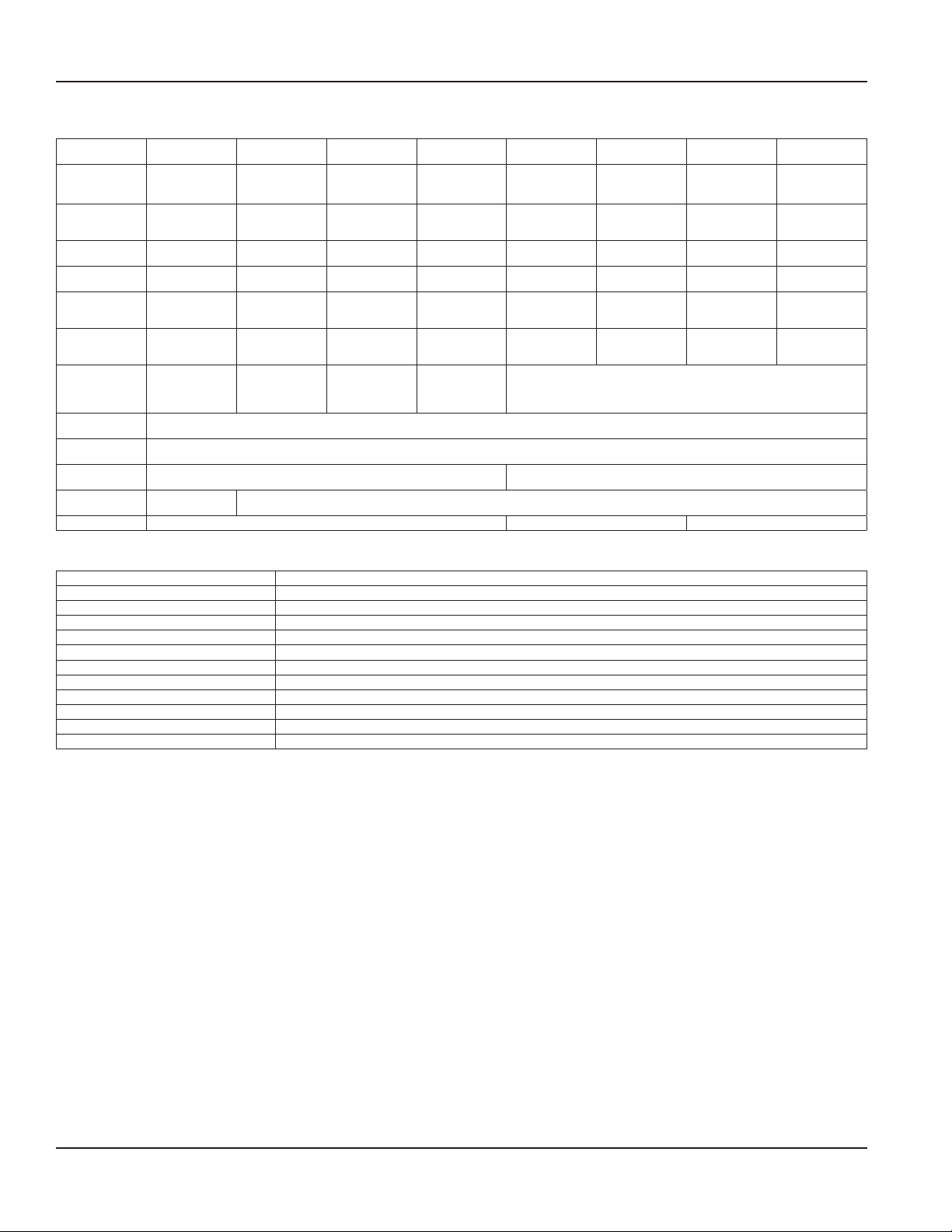
SPECIFICATIONS
Turbo Series
Model
Meter Flanges
AWWA 125
Pound Class
Typical
Operating Range
(100% ± 1.5%)
Typical Low Flow
(95% min.)
Max. Continuous
Flow
Maximum
Intermittent
Flow
Pressure Loss at
Max. Continuous
Flow
Pressure Loss at
Max. Continuous
Flow: With
Integral Strainer
Max. Operating
Pressure
Max. Operating
Temperature
Optional Integral
Strainer
Optional
External Strainer
Test Plug Standard with integral strainer; optional for other models. Optional for Models 2000 and 3500. —
160
1-1/2 in. (40 mm)
Elliptical Elliptical or Round Round Round Round Round Round
4…200 gpm
(0.9…45.4 m3/h)
2.5 gpm (0.6 m3/h) 2.5 gpm (0.6 m3/h) 4 gpm (0.9 m3/h) 6 gpm (1.4 m3/h) 12 gpm (2.7 m3/h) 20 gpm (4.5 m3/h) 30 gpm (6.8 m3/h)
160 gpm
(36 m3/h)
200 gpm
(45.4 m3/h)
3.8 psi (0.26 bar) 3.1 psi (0.21 bar) 1.8 psi (0.12 bar) 7.3 psi (0.50 bar) 4.8 psi (0.33 bar) 2.5 psi (0.17 bar) 1.6 psi (0.11 bar) 0.8 psi (0.05 bar)
9.9 psi (0.68 bar) 8.3 psi (0.57 bar) 5 psi (0.43 bar) 17.8 psi (1.2 bar) —
Removable cover plate permits access to strainer for cleaning.
— Available for Models 200, 450, 1000, 2000, 3500, 5500 and 6200.
200
2 in. (50 mm)
4…310 gpm
(0.9…70.4 m3/h)
200 gpm
(45.4 m3/h)
310 gpm
(70.4 m3/h)
Built into inlet end.
450
3 in. (80 mm)
5…550 gpm
(1.1…124.9 m3/h)
450 gpm
(102.2 m3/h)
550 gpm
(124.9 m3h)
1000
4 in. (100 mm)
10…1250 gpm
(2.3…284 m3/hr)
1000 gpm
(227.1 m3/h)
1250 gpm
(284 m3h)
150 psi (10 bar)
120° F (49° C)
2000
6 in. (150 mm)
20…2500 gpm
(4.5…568 m3/h)
2000 gpm
(454 m3/h)
2500 gpm
(568 m3/h)
3500
8 in. (200 mm)
30…4500 gpm
(6.8…1022 m3/h)
3500 gpm
(795 m3/h)
4500 gpm
(1022 m3/h)
5500
10 in. (250 mm)
50…7000 gpm
(11.4…1590 m3/h)
5500 gpm
(1250 m3/h)
7000 gpm
(1590 m3h)
—
6200
12 in. (300 mm)
Round
AWWA 125 lb
class
90…8800 gpm
(20.5…1998 m3/h)
65 gpm
(14.8 m3/h)
6200 gpm
(1408 m3/h)
8800 gpm
(1988 m3/h)
MATERIALS
Meter Housing Lead-free alloy (EXCEPTION: Model 6200 meter housing is blue epoxy-coated cast iron)
Turbo Head Lead-free alloy
Nose Cone & Straightening Vanes Thermoplastic
Rotor Thermoplastic
Rotor Radial Bearings Lubricated thermoplastic
Rotor Thruster Bearing Sapphire jewels
Rotor Bearing Pivots Passivated 316 stainless steel
Calibration Mechanism Stainless steel & thermoplastic
Magnet Ceramic
Trim Stainless steel
Register Housing & Cover Thermoplastic or bronze
Optional Strainer and Trim Stainless steel
Page 2 November 2016RTS-DS-00320-EN-06
Page 3
Product Data Sheet
0
0,1
0,4
0,5
0,6
0,7
0,8
0,9
0,2
0,3
Badger Meter
®
64085-009
®
T-160
Recordall
m
3
1-1/2"
0
1
4
5
6
7
8
9
2
3
Badger Meter
®
64085-023
®
T-2000
Recordall
m
3
6"
0
1
4
5
6
7
8
9
2
3
Badger Meter
®
64085-045
®
T-6200
Recordall
m
3
12"
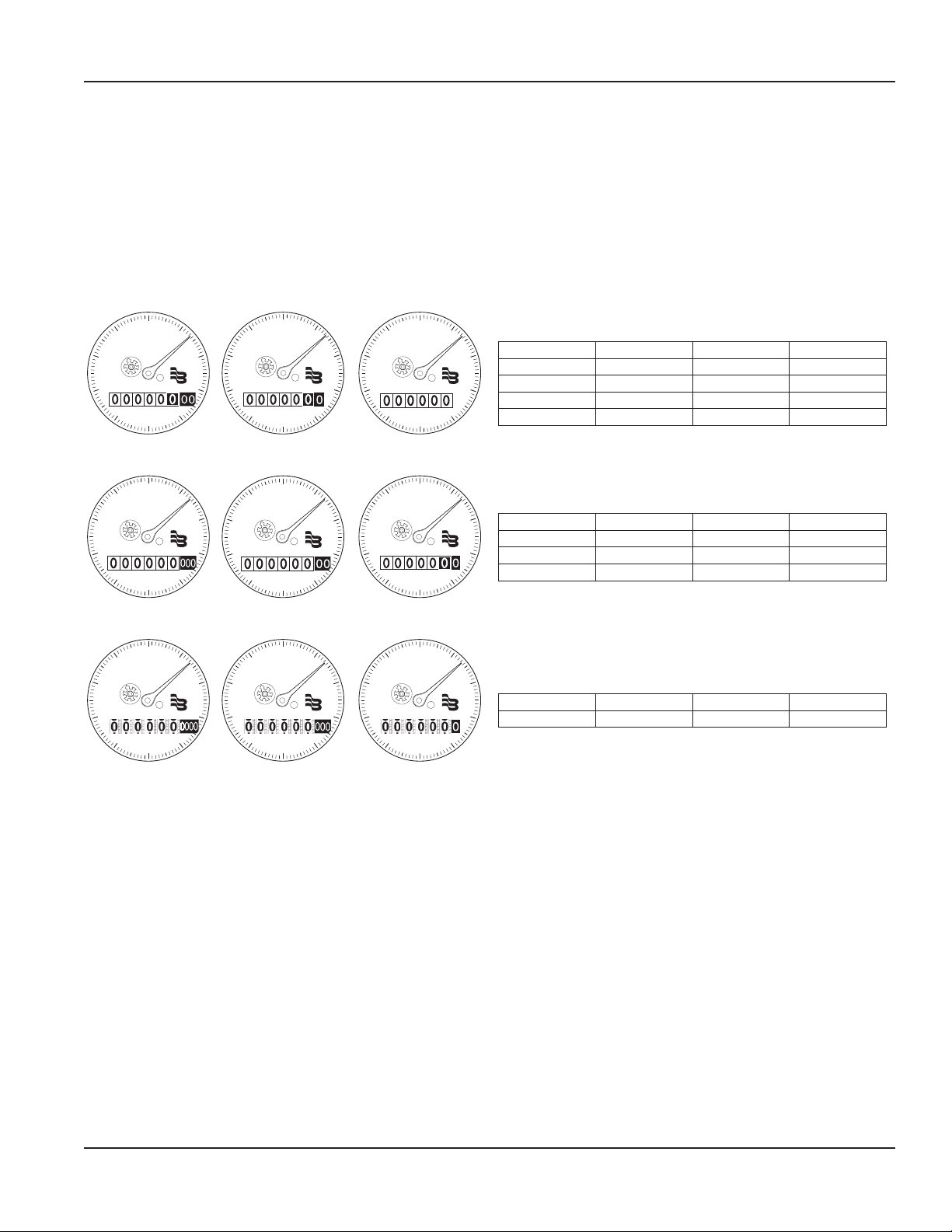
REGISTERS / ENCODERS
Standard—Sweep-Hand Registration
The standard register is a straight-reading, permanently sealed magnetic drive register. Dirt, moisture, tampering and lens fogging
problems are eliminated. The register has a six-odometer wheel totalization display, 360° test circle with center sweep hand, and flow finder
to detect leaks. Register gearing is made of self-lubricating engineered polymer, which minimizes friction and provides long life. The multiposition register simplifies meter installation and reading. The register capacity for the 1-1/2 in., 2 in., 3 in. and 4 in. meters is 100,000,000
gallons (10,000,000 ft3, 1,000,000 m3). The register capacity for the 6 in., 8 in., and 10 in. meters is 1,000,000,000 gallons (100,000,000 ft3,
10,000,000 m3). The high-flow register capacity for the 12 in. meter is 10,000,000,000 gallons (1,000,000,000 ft3, 10,000,000 m3).
Registers for 1-1/2 in., 2 in., 3 in. and 4 in. Meters
9
6
0
Recordall
T-160
1-1/2"
Cubic Feet
5
1
®
Badger Meter
®
4
80
64085-001
70
0
Recordall
1-1/2"
Gallons
T-160
50
10
®
8
20
Badger Meter
®
64085-005
30
7
40
90
60
Registers for 6 in., 8 in. and 10 in. Meters
800
64085-017
700
900
600
Recordall
T-2000
6"
Gallons
500
0
100
®
200
300
80
64085-020
70
Badger Meter
®
400
90
60
0
Recordall
T-2000
6"
Cubic Feet
50
10
®
Badger Meter
®
40
Registers for 12 in. Meters
8000
64085-043
7000
9000
6000
Recordall
T-6200
12"
Gallons
5000
0
1000
®
Badger Meter
®
®
2000
3000
800
64085-044
700
4000
900
600
0
Recordall
T-6200
12"
Cubic Feet
500
100
®
Badger Meter
®
400
200
300
Sweep Hand Revolution
2
3
Meter Model Gallon Cubic Feet Cubic Meter
160 100 10 1
200 100 10 1
450 100 10 1
1000 100 10 1
Sweep Hand Revolution
20
30
Meter Model Gallon Cubic Feet Cubic Meter
2000 1000 100 10
3500 1000 100 10
5500 1000 100 10
Sweep Hand Revolution
Meter Model Gallon Cubic Feet Cubic Meter
6200 10000 1000 10
Optional—Encoders for AMR/AMI Reading Solutions
AMR/AMI solutions are available for all Recordall Disc Series meters. All reading options can be removed from the meter without
disrupting water service. Badger Meter encoders provide years of reliable, accurate readings for a variety of applications and are also
available pre-wired to Badger Meter approved AMR/AMI solutions. See details at www.badgermeter.com.
Page 3 November 2016 RTS-DS-00320-EN-06
Page 4
Recordall® Turbo Series Meters
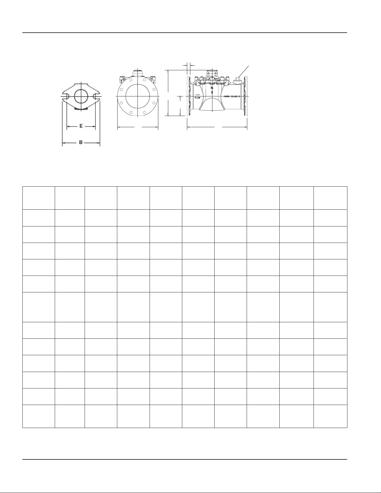
PHYSICAL DIMENSIONS OF METERS WITHOUT STRAINER
Turbo
Series
Model
Meter
Flanges
Meter &
Pipe Size
Net
Weight
Shipping
Weight
Qty. of
Bolts
NPT Test
Port &
Test Plug
(optional)
Length
(A)
Width
(B )
Height
(C)
Flange
(D)
Bolt Circle
(E)
Centerline
(F)
D
NPT Test Port & Test Plug
(1-1/2 . . . 8”)
C
F
B A
Figure 1: Sample Illustration from 8 in. Model 3500
160 200 200 450 1000 2000 3500 5500 6200
1-1/2 in.
Elliptical
1-1/2 in.
(40 mm)
14.3 lb
(6.5 kg)
16.8 lb
(7.6 kg)
2 2 4 4 8 8 8 12 12
1 in.
(25.4 mm)
13 in.
(330 mm)
5-7/32 in.
(133 mm)
6-9/32 in.
(159 mm)
51/64 in.
(20 mm)
4 in.
(102 mm)
1-27/32
in.
(47 mm)
2 in.
Elliptical
2 in.
(50 mm)
14.9 lb
(6.8 kg)
16.4 lb
(7.4 kg)
1-1/2 in.
(40 mm)
10 in.
(254 mm)
5-27/32 in.
(148 mm)
6-1/2 in.
(165 mm)
25/32 in.
(20 mm)
4-1/2 in.
(114 mm)
2-1/16 in.
(52 mm)
2 in. Round 3 in. Round 4 in. Round 6 in. Round 8 in. Round
2 in.
(50 mm)
17.4 lb
(7.9 kg)
18.9 lb
(8.6 kg)
1-1/2 in.
(40 mm)
10 in.
(254 mm)
6 in.
(152 mm)
7-3/32 in.
(180 mm)
5/8 in.
(16 mm)
4-3/4 in.
(121 mm)
2-5/8 in.
(67 mm)
3 in.
(80 mm)
31 lb
(14.1 kg)
34 lb
(15.4 kg)
2 in.
(50 mm)
12 in.
(305 mm)
7-1/2 in.
(191 mm)
8-11/16 in.
(220 mm)
3/4 in.
(19 mm)
6 in.
(152 mm)
3-11/32 in.
(85 mm)
4 in.
(100 mm)
40 lb
(18.1 kg)
45 lb
(20.4 kg)
2 in.
(50 mm)
14 in.
(356 mm)
9 in.
(229 mm)
9-21/32 in.
(245 mm)
13/16 in.
(21 mm)
7-1/2 in.
(191 mm)
4-5/16 in.
(109 mm)
6 in.
(150 mm)
77 lb
(35 kg)
89 lb
(40.4 kg)
2 in.
(50 mm)
18 in.
(457 mm)
11 in.
(280 mm)
13-5/16 in.
(338 mm)
7/8 in.
(22 mm)
9-1/2 in.
(241 mm)
5-1/4 in.
(133 mm)
8 in.
(200 mm)
123 lb
(55.7 kg)
147 lb
(66.6 kg)
2 in.
(50 mm)
20 in.
(508 mm)
13-1/2 in.
(343 mm)
15-3/16 in.
(385 mm)
1 in.
(25 mm)
11-3/4 in.
(298 mm)
6-3/8 in.
(162 mm)
10 in.
Round
10 in.
(250 mm)
210 lb
(95.3 kg)
235 lb
(106.6 kg)
— —
26 in.
(660.4 mm)
16 in.
(406.4 mm)
17-15/32 in.
(443 mm)
1-1/16 in.
(27 mm)
14-1/4 in.
(362 mm)
7-7/8 in.
(199.4 mm)
19-11/16 in.
19-11/16 in.
12 in.
Round
12 in.
(300 mm)
262 lb
(118.8 kg)
286 lb
(129.7 kg)
(500 mm)
19 in.
(482 mm)
(500 mm)
1.26 in.
(32 mm)
17 in.
(432 mm)
8-7/8 in.
(226 mm)
Page 4 November 2016RTS-DS-00320-EN-06
Page 5

Product Data Sheet
PHYSICAL DIMENSIONS OF METERS WITH INTEGRAL STRAINER
Figure 2: Physical dimensions
Turbo Series Model 160 200 200 450 1000
Meter Flanges Elliptical Elliptical Round Round Round
Meter & Pipe Size 1-1/2 in. (40 mm) 2 in. (50 mm) 2 in. (50 mm) 3 in. (80 mm) 4 in. (100 mm)
Net Weight 14.3 lb (6.5 kg) 24 lb (11 kg) 26 lb (12 kg) 49 lb (22 kg) 60 lb (27.22 kg)
Shipping Weight 16.8 lb (7.6 kg) 28 lb (13 kg) 30 lb (14 kg) 55 lb (25 kg) 70 lb (31.75 kg)
Number of Bolts 2 2 4 4 8
NPT Test Port
& Test Plug
(Standard)
Length (A) 13 in. (330 mm) 17 in. (432 mm) 17 in. (432 mm) 19 in. (483 mm) 23 in. (584 mm)
Width (B ) 5-7/32 in. (133 mm) 5-27/32 in. (148 mm) 6 in. (152 mm) 7-1/2 in. (191 mm) 9 in. (229 mm)
Height (C) 6-9/32 in. (159 mm) 6-1/2 in. (165 mm) 7-3/32 in. (180 mm) 8-15/16 in. (227 mm) 9-21/32 in. (245 mm)
Flange (D) 51/64 in. (20 mm) 27/32 in. (47 mm) 5/8 in. (16 mm) 27/32 in. (21 mm) 13/16 in. (21 mm)
Bolt Circle (E) 4 in. (102 mm) 4-1/2 in. (114 mm) 4-3/4 in. (121 mm) 6 in. (152 mm) 7-1/2 in. (191 mm)
Centerline (F) 1-27/32 in. (47 mm) 2-1/16 in. (52 mm) 2-5/8 in. (67 mm) 3-19/32 in. (91 mm) 4-5/16 in. (109 mm)
1 in. (25.4 mm) 1-1/2 in. (40 mm) 1-1/2 in. (40 mm) 2 in. (50 mm) 2 in. (50 mm)
Page 5 November 2016 RTS-DS-00320-EN-06
Page 6

Recordall® Turbo Series Meters
Pressure Loss
PSI
1 10 100 1000 10000
25
20
15
10
5
0
1.5 in.
2 in.
3 in.
4 in.
6 in.
8 in.
10 in.
12 in.
PRESSURE LOSS CHART FOR METERS WITHOUT STRAINER
Rate of flow in gallons per minute (gpm)
PRESSURE LOSS CHART FOR METERS WITH INTEGRAL STRAINER
Rate of flow in gallons per minute (gpm)
2 4 6 8 20 40 60 80 200 800600400
25
20
15
P.S.I.
10
Pressure Loss
5
0
10 100 10001
1.5”
1.5”
2”
4”
3”
Page 6 November 2016RTS-DS-00320-EN-06
Page 7

ACCURACY CHARTS FOR METERS WITHOUT STRAINER
Accuracy Per Cent
1
100
100010
Under
1
100
100010
110100 1000 10000
Rate of flow in gallons per minute (gpm)
Product Data Sheet
1-1/2 in. Meter
2 in. Meter
10
5
Over
Register
+
0
-
5
10
Under
Register
15
10
5
Over
Register
+
0
-
5
Accuracy Per Cent
10
Register
15
2468 20 40 60 80
2468 20 40 60 80
200 400 600 800
200 400 600 800
3 in. Meter
4 in. Meter
2648 20 40 60 80 200400 800 2000600 3000 8000
10
5
Over
Register
+
0
-
5
10
Accuracy Per Cent
Under
Register
15
Page 7 November 2016 RTS-DS-00320-EN-06
Page 8

Recordall® Turbo Series Meters
100
10
10000
1000
Accuracy Per Cent
Register
Under
ACCURACY CHARTS FOR METERS WITHOUT STRAINER CONTINUED
Rate of flow in gallons per minute (gpm)
6 in. Meter
Over
Register
Accuracy Per Cent
Undar
Register
8 in. Meter
10 in. Meter
12 in. Meter
1 10 100 1000 10000
10
5
Over
Register
+
0
-
5
Accuracy Per Cent
10
Under
Register
15
10
5
Register
Over
+
0
-
5
10
15
4 6 8 20 40 60 80 200 4002 600 800 2000 4000 6000 8000
80604020
800600400200
8000600040002000
Page 8 November 2016RTS-DS-00320-EN-06
Page 9

ACCURACY CHARTS FOR METERS WITH INTEGRAL STRAINER
100 10001 10
Accuracy Per Cent
Rate of flow in gallons per minute (gpm)
Product Data Sheet
1-1/2 in. Meter
2 in. Meter
10
5
Over
Register
+
0
-
5
10
Accuracy Per Cent
Under
Register
15
1 100 100010
10
5
Over
Register
+
0
-
5
10
Under
Register
15
2 4 6 8 20 40 60 80 200 400 600 800
2 4 6 8 20 40 60 80 2OO 400 600 800
3 in. Meter
4 in. Meter
Page 9 November 2016 RTS-DS-00320-EN-06
Page 10

Recordall® Turbo Series Meters
INTENTIONAL BLANK PAGE
Page 10 November 2016RTS-DS-00320-EN-06
Page 11

INTENTIONAL BLANK PAGE
Product Data Sheet
Page 11 November 2016 RTS-DS-00320-EN-06
Page 12

Recordall® Turbo Series Meters
Making Water Visible®
MAKING WATER VISIBLE and RECORDALL are registered trademarks of Badger Meter, Inc. Other trademarks appearing in this document are the property of their respective entities.
Due to continuous research, product improvements and enhancements, Badger Meter reserves the right to change product or system specications without notice, except to the
extent an outstanding contractual obligation exists. © 2016 Badger Meter, Inc. All rights reserved.
www.badgermeter.com
The Americas | Badger Meter | 4545 West Brown Deer Rd | PO Box 245036 | Milwaukee, WI 53224-9536 | 800-876-3837 | 414-355-0400
México | Badger Meter de las Americas, S.A. de C.V. | Pedro Luis Ogazón N°32 | Esq. Angelina N°24 | Colonia Guadalupe Inn | CP 01050 | México, DF | México | +52-55-5662-0882
Europe, Middle East and Africa | Badger Meter Europa GmbH | Nurtinger Str 76 | 72639 Neuen | Germany | +49-7025-9208-0
Europe, Middle East Branch Oce | Badger Meter Europe | PO Box 341442 | Dubai Silicon Oasis, Head Quarter Building, Wing C, Oce #C209 | Dubai / UAE | +971-4-371 2503
Czech Republic | Badger Meter Czech Republic s.r.o. | Maříkova 2082/26 | 621 00 Brno, Czech Republic | +420-5-41420411
Slovakia | Badger Meter Slovakia s.r.o. | Racianska 109/B | 831 02 Bratislava, Slovakia | +421-2-44 63 83 01
Asia Pacic | Badger Meter | 80 Marine Parade Rd | 21-04 Parkway Parade | Singapore 449269 | +65-63464836
China | Badger Meter | 7-1202 | 99 Hangzhong Road | Minhang District | Shanghai | China 201101 | +86-21-5763 5412
Switzerland I Badger Meter Swiss AG I Mittelholzerstrasse 8 I 3006 Bern I Switzerland I +41-31-932 01 11 Legacy Document Numbers: RTS-T-1-1/2. 3. 4. 6. 8. 10 and 12; RTS-T-I 1-1/2, 2, 3, and 4
 Loading...