

Page 1
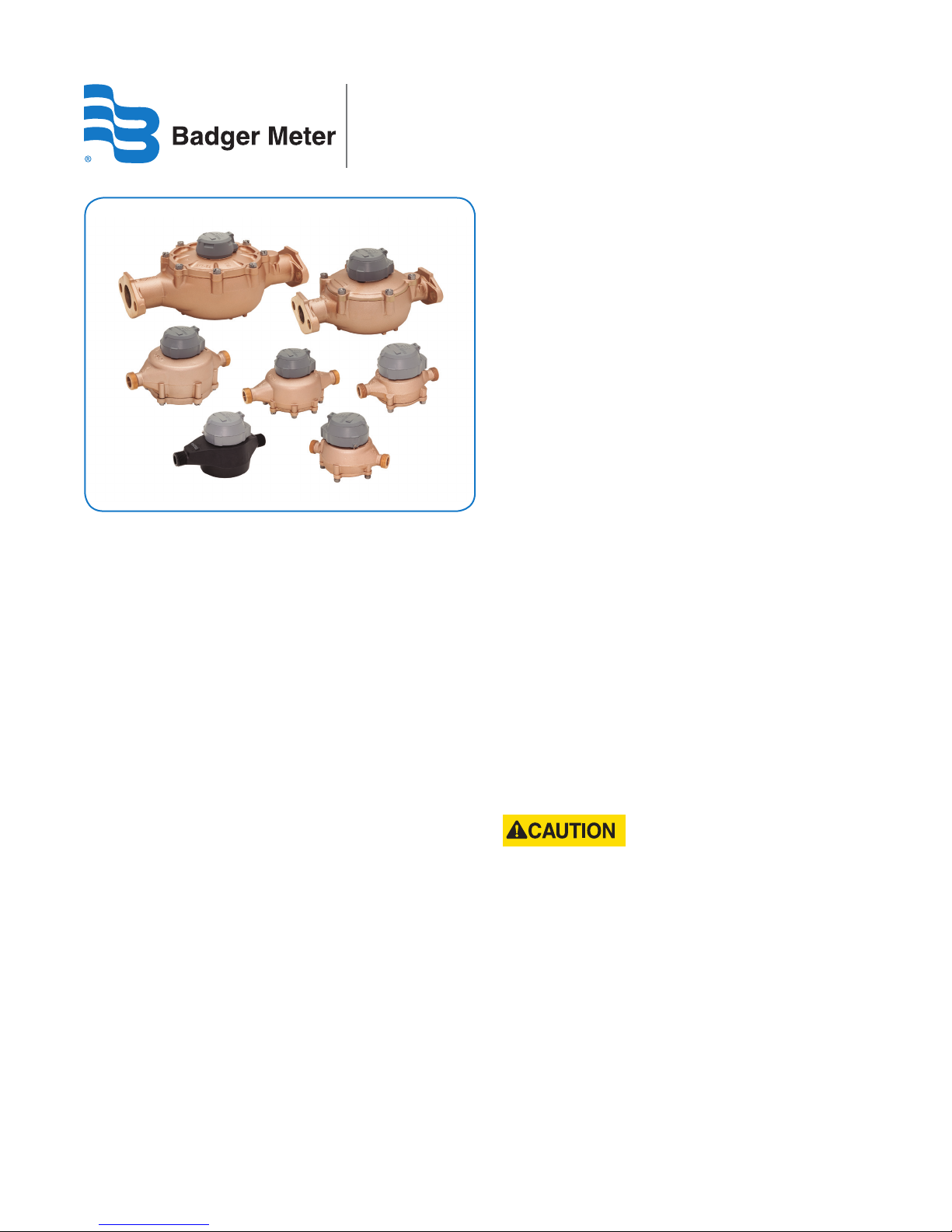
Recordall® Disc Series Meters
Cold Water Disc Meters, 5/8 in. to 2 in.
SAFETY INFORMATION
The installation of the Recordall® Disc Series Meters must
comply with all applicable federal, state, and local rules,
regulations, and codes.
Failure to read and follow these instructions can lead to
misapplication or misuse of the Recordall® Disc Series Meters,
resulting in personal injury and damage to equipment.
PRODUCT UNPACKING AND
INSPECTION
Upon opening the shipping container, visually inspect the
product and applicable accessories for any physical damage
such as scratches, loose or broken parts, or any other sign of
damage that may have occurred during shipment.
OTE:N If damage is found, request an inspection by
the carrier’s agent within 48 hours of delivery
and file a claim with the carrier. A claim for
equipment damage in transit is the sole
responsibility of the purchaser.
METER PREINSTALLATION
Take into account the following considerations before you
begin an installation:
• Inspect the piping around the meter for suitable
conditions. The service line, valves, connections and
meter must be watertight. Repair the piping system if
pipes are corroded or damaged.
• Install the meter in the pipeline in a horizontal position
so that the flow arrow on the meter housing points in
the same direction as water flow. Registration should be
upright and protected from damage, freezing,
and tampering.
• Position the meter so it is accessible for installation,
removal and reading.
• Verify that a suitable electrical grounding wire is properly
attached to the upstream and downstream pipe
connections of the meter. The grounding wire provides an
alternative path for any electrical current that may exist
across the opening in the line.
• Close the curb (shutoff) valve to relieve water pressure in
the line before starting the cutting operation. Provide a
high-quality upstream shut-off valve with a low
pressure drop.
• When cutting into a new section of service pipe,
flush the pipe to clear chips, pipe dope or other
plumbing residue.
• The installed meter must not be an obstacle or a hazard
to the customer or interfere with public safety.
• DO NOT ATTEMPT TO USE ANY METER AS A LEVER OR
CROWBAR TO STRAIGHTEN A MISALIGNED METER
POSITION. THIS COULD DAMAGE THE METER.
• DO NOT ATTEMPT TO INSTALL A METER INTO AN
OPENING THAT IS TOO LONG BY FORCING THE PIPING
INTO PLACE WITH THE METER'S COUPLING NUTS. THIS
WILL CAUSE SERIOUS DAMAGE TO THE THREADED ENDS
OF THE METER AND HOUSING.
RDM-UM-00059-EN-05 (January 2018)
• TO AVOID POTENTIAL PROBLEMS, CORRECT ANY
IRREGULARITIES IN PIPE SPACING AND MISALIGNMENT
BEFORE PLACING THE METER INTO ITS POSITION.
Installation Manual
Page 2
Recordall® Disc Series Meters, Cold Water Disc Meters, 5/8 in. to 2 in.
SPECIAL INSTRUCTIONS FOR REMOVING A METER
DEPRESSURIZE THE LINE BEFORE STARTING ANY DISASSEMBLY OPERATION. REMOVING A METER THAT IS UNDER LINE
PRESSURE CAN RESULT IN COMPONENTS BECOMING PROJECTILES, CAPABLE OF CAUSING PERSONAL INJURY.
SPECIAL FITTINGS AND ACCESSORIES
To accommodate 5/8 in., 3/4 in. and 1 in. meter installations, special fittings and accessories are available. Metal meter setters,
re-setters, horns and meter yokes are available for holding the service pipe in proper alignment to the meter and laying
length spacing. The metal setters and meter yokes can provide an electrical continuity to protect meters and consumers from
electrical shocks.
NL bronze connections are available from Badger Meter. To compensate for minor service pipe and setting misalignment for a
5/8 in., 3/4 in. and 1 in. meter, plastic swivel connections are also available.
Cast iron or NL bronze companion flanges are available for a 1-1/2 in. and 2 in. meter.
INSTALLING RECORDALL DISC SERIES METERS
Outdoor Installations
When installed outdoors in a meter box, the disc meter should have a two- to three-inch clearance
to avoid damage or strain to the service piping or meter, and to accommodate any "settling" that
may occur after installation.
The service pipe in the meter box should be properly bedded to ensure that it is not axially
misaligned and that it lays evenly on the bottom of the pipe trench. The backfill material covering
the pipe should be placed appropriately to maintain pipe alignment in the event of eventual
ground shifts. This will prevent damage to the pipe.
The service lines and the water meter must be protected from freezing. The earth covering the service line must be adequate
to prevent frost penetration. Due to the smaller volume of water, service line pipes will freeze sooner than the main
distribution line.
For those locations in which a remote possibility of freezing exists, thermoplastic or lead-free bronze alloy meters with cast
iron bottoms are recommended.
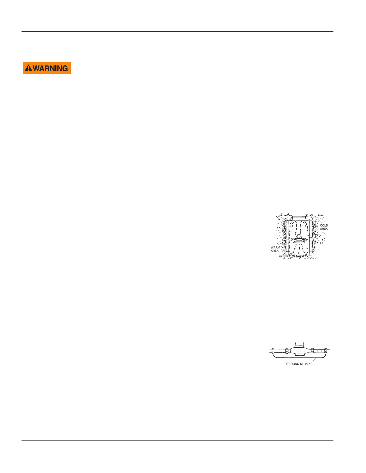
The meter box pit should be excavated below the frost line. Even though the meter itself may be positioned above the frost
line, the warmer air rising from the earth below the frost line will reduce the possibility of freezing.
Indoor Installations
As a precautionary measure when working with metallic pipes, indoor settings must be checked
for electrical continuity through the service pipe before you remove or service a meter. American
Water Works Association (AWWA) policy specifies that service pipes must not be used as an
electrical ground. Check your local codes and practices. A permanent ground strap or metal setter
must be used if electrical grounding to water services is required in your community.
This is especially important for the engineered polymer meter.
To prevent floor damage, close the valve downstream from the meter before installing or removing a meter.
Page 2 January 2018
RDM-UM-00059-EN-05
Page 3

Installation Manual
INSTALLATION INSTRUCTIONS
To prepare for meter installation, follow these steps:
1. Close the meter's inlet-side valve.
2. Open a faucet and wait until water ow stops, to depressurize the system. Do not remove the meter until the
ow stops.
3. Check valves and make necessary repairs to the curb (shut-o) valve or inlet side valve if necessary.
4. Close the meter's outlet-side valve. Protect the floor below the meter against potential spills or leaks that could occur.
Protect the coupling area from debris, so that the new meter will not be damaged or contaminated.
5. To replace an existing meter, continue with Step 6. To install a new meter, skip to Step 8.
6. Loosen meter couplings or ange bolts and remove the meter and the old gaskets in the coupling nuts.
MPORTANTI
Replace the entire connection set when you replace the meter (or earlier, if necessary).
7. Clean the coupling nuts or ange ends, removing any pipe dope or dirt from the threads or ange ends.
8. Check the existing setting for proper alignment and spacing. Correct any misalignment and spacing in the setting.
9. Place the new connection gaskets inside the connection coupling nuts.
10. Install the meter in the pipeline in a horizontal position so that the flow arrow on the meter housing points in the
same direction as water flow.
5/8 in. to 2 in. Threaded Ends
11. Start the coupling nuts at the threaded meter ends. Verify that the nuts are properly aligned to avoid cross-threading
or damage to the meter ends. This is especially important for the engineered polymer meter.
An effective method for starting a coupling nut is:
a. Position the nut squarely against the meter's spud end.
b. Turn the nut counterclockwise (in reverse) while holding the nut against the meter spud end. When the rst
threads on both the nut and the spud end coincide, you will hear a slight click and feel the nut move into the
starting position.
c. Tighten the nut by hand until it is snug.
d. With an open-end wrench, apply a partial turn. Do not over tighten. For plastic swivel connections, a
one-quarter turn is usually sucient.
1-1/2 in. to 2 in. Elliptical Flange Ends
12. With meter and gaskets in place, tighten the ange connection bolts. Verify the nuts are properly aligned to avoid
damage to the anged ends.
PROTECT AGAINST LEAKAGE
Before turning on the service water, use care to protect against potential leakage.
1. Shut o the valves on both the inlet and outlet sides of the meter.
2. Open the curb (shuto) valve slowly to pressurize the service line to the meter.
3. Slowly open the meter's inlet-side valve to ll the meter.
4. Check for leaks around the meter and its connections.
5. Slowly open the meter's outlet-side valve to pressurize the consumer side of the system.
6. Open a faucet to allow entrapped air to escape.
7. Once water is owing normally, turn o the faucet.
RDM-UM-00059-EN-05
Page 3 January 2018
Page 4

Recordall® Disc Series Meters, Cold Water Disc Meters, 5/8 in. to 2 in.
Making Water Visible®
Recordall is a registered trademark of Badger Meter Inc. Other trademarks appearing in this document are the property of their respective entities. Due to continuous research,
product improvements and enhancements, Badger Meter reserves the right to change product or system specications without notice, except to the extent an outstanding contractual obligation exists. © 2018 Badger Meter, Inc. All rights reserved.
www.badgermeter.com
The Americas | Badger Meter | 4545 West Brown Deer Rd | PO Box 245036 | Milwaukee, WI 53224-9536 | 800-876-3837 | 414-355-0400
México | Badger Meter de las Americas, S.A. de C.V. | Pedro Luis Ogazón N°32 | Esq. Angelina N°24 | Colonia Guadalupe Inn | CP 01050 | México, DF | México | +52-55-5662-0882
Europe, Eastern Europe Branch Oce (for Poland, Latvia, Lithuania, Estonia, Ukraine, Belarus) | Badger Meter Europe | ul. Korfantego 6 | 44-193 Knurów | Poland | +48-32-236-8787
Europe, Middle East and Africa | Badger Meter Europa GmbH | Nurtinger Str 76 | 72639 Neuen | Germany | +49-7025-9208-0
Europe, Middle East Branch Oce | Badger Meter Europe | PO Box 341442 | Dubai Silicon Oasis, Head Quarter Building, Wing C, O ce #C209 | Dubai / UAE | +971-4-371 2503
Slovakia | Badger Meter Slovakia s.r.o. | Raciansk a 109/B | 831 02 Bratislava, Slovak ia | +421-2-44 63 83 01
Asia Pacic | Badger Meter | 80 Marine Parade Rd | 21-06 Parkway Parade | Singapore 449269 | +65-63464836
China | Badger Meter | 7-1202 | 99 Hangzhong Road | Minhang District | Shanghai | China 201101 | +86-21-5763 5412
Switzerland | Badger Meter Swiss AG | Mittelholzerstrasse 8 | 3006 Bern | Switzerland | +41-31-932 01 11
Legacy Document Number: RD-I-01
 Loading...