

Page 1
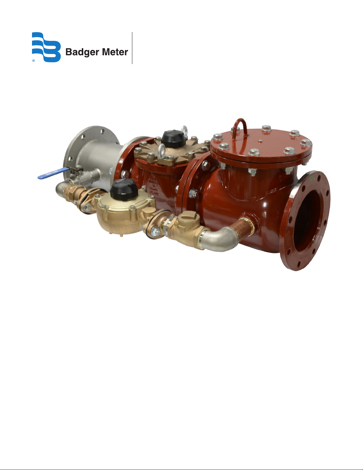
Recordall® Combo Meter
Lead-Free Bronze Alloy, Size 8" (DN 200)
NSF/ANSI Standards 61 and 372 Certied
RCO-UM-00077-EN-02 (October 2013)
User Manual
Page 2

Recordall® Combo Meter, 8"
Page ii October 2013
Page 3

User Manual
CONTENTS
SCOPE OF THE MANUAL. . . . . . . . . . . . . . . . . . . . . . . . . . . . . . . . . . . . . . . . . . . . . . . . . . . . . . . . . . . . . . . . . 5
PRODUCT INFORMATION. . . . . . . . . . . . . . . . . . . . . . . . . . . . . . . . . . . . . . . . . . . . . . . . . . . . . . . . . . . . . . . . 5
Product Description . . . . . . . . . . . . . . . . . . . . . . . . . . . . . . . . . . . . . . . . . . . . . . . . . . . . . . . . . . . . . . . . . 5
Related Literature . . . . . . . . . . . . . . . . . . . . . . . . . . . . . . . . . . . . . . . . . . . . . . . . . . . . . . . . . . . . . . . . . . 5
Safety Information . . . . . . . . . . . . . . . . . . . . . . . . . . . . . . . . . . . . . . . . . . . . . . . . . . . . . . . . . . . . . . . . . . 5
Unpacking and Inspection. . . . . . . . . . . . . . . . . . . . . . . . . . . . . . . . . . . . . . . . . . . . . . . . . . . . . . . . . . . . . 5
INSTALLATION . . . . . . . . . . . . . . . . . . . . . . . . . . . . . . . . . . . . . . . . . . . . . . . . . . . . . . . . . . . . . . . . . . . . . . . 6
Installing the Meter . . . . . . . . . . . . . . . . . . . . . . . . . . . . . . . . . . . . . . . . . . . . . . . . . . . . . . . . . . . . . . . . . 7
Performance Checks and System Startup . . . . . . . . . . . . . . . . . . . . . . . . . . . . . . . . . . . . . . . . . . . . . . . . . . . 7
Shutdown Instructions . . . . . . . . . . . . . . . . . . . . . . . . . . . . . . . . . . . . . . . . . . . . . . . . . . . . . . . . . . . . . . . 7
SERVICING PARTS AND ASSEMBLIES. . . . . . . . . . . . . . . . . . . . . . . . . . . . . . . . . . . . . . . . . . . . . . . . . . . . . . . . . 8
Maintenance . . . . . . . . . . . . . . . . . . . . . . . . . . . . . . . . . . . . . . . . . . . . . . . . . . . . . . . . . . . . . . . . . . . . . 8
Calibration Check and Adjustment . . . . . . . . . . . . . . . . . . . . . . . . . . . . . . . . . . . . . . . . . . . . . . . . . . . . . . 10
BYPASS COMPONENTS HEAD ASSEMBLIES . . . . . . . . . . . . . . . . . . . . . . . . . . . . . . . . . . . . . . . . . . . . . . . . . . . 11
Check Valve . . . . . . . . . . . . . . . . . . . . . . . . . . . . . . . . . . . . . . . . . . . . . . . . . . . . . . . . . . . . . . . . . . . . . 12
SPECIFICATIONS. . . . . . . . . . . . . . . . . . . . . . . . . . . . . . . . . . . . . . . . . . . . . . . . . . . . . . . . . . . . . . . . . . . . . 13
Materials . . . . . . . . . . . . . . . . . . . . . . . . . . . . . . . . . . . . . . . . . . . . . . . . . . . . . . . . . . . . . . . . . . . . . . . 13
Page iii October 2013
Page 4

Recordall® Combo Meter, 8"
Page iv October 2013
Page 5

User Manual
SCOPE OF THE MANUAL
This manual contains information concerning the installation, operation and maintenance of the 8" Badger Meter® Recordall®
Combo Meter Assembly. To ensure efficient operation of the meters, read and understand the instructions in this manual.
Retain the manual in a location where it is readily available.
PRODUCT INFORMATION
Product Description
The 8" Recordall Combo Meter assembly consists of a stainless steel spool with a bypass port, an 8" Recordall Turbo Series
Meter with AWWA class II measuring chamber, a Model DCA-01 Detector Check Valve with bypass piping, valves, and an M120
Recordall Disc Meter. The meter assembly measures both low flow domestic use and high volume use through a single water
supply line.
Turbine Meter
Water flows into the meter's measuring element, contacting the multi-vaned rotor. Flow readings are obtained by rotor
revolutions transmitted by magnetic drive coupling through the meter's cover plate to the sealed register. Magnetic drive
is achieved by a right angle worm drive, coupling the rotor to a vertical transmission spindle, driving a gear set rotating
the magnet carrier. A ceramic magnet in a carrier rotates around a vertical axis. Rotor rotation is transmitted to the register
gearing through this magnetic coupling.
The turbo measuring element is designed to greatly reduce wear by reducing friction potential between the moving parts
of the rotor and bearing system. Less wear, in this critical area of the design, provides the utility manager with a lower
lifecycle cost for meter application. Throughout the normal operating range of the meter, the rotor floats between the thrust
bearing system.
The detector check valve is a spring-loaded check valve on the downstream side of the clapper that holds the clapper in a
normally closed position. Small water flows bypass the clapper and are registered on the 1-1/2" bypass meter. This allows
for accurate registration of domestic use, leakage or misuse of water. When a major flow is required, the water pressure
overcomes the mechanical advantages of the spring-loaded clapper and pushes it open, permitting full pipe capacity flow. A
small amount of water continues to flow through the bypass when the clapper is fully open.
The bypass line consists of piping with a 1-1/2" Model 120 Recordall Disc Meter, an isolation valve, and a check valve.
Related Literature
• The Recordall Combo Meters Product Data Sheet contains information on operating principle, meter construction, materials,
tolerances and specifications.
• The Recordall Combo Meters Parts List contains illustrations of parts, part numbers, and part descriptions.
Safety Information
The installation of the Recordall Combo meter must comply with all applicable federal, state, and local rules, regulations,
and codes.
Failure to read and follow these instructions can lead to misapplication or misuse of the meter, resulting in personal injury and
damage to equipment.
Unpacking and Inspection
To avoid damage in transit, the Recordall Combo meter assemblies are shipped to the customer in special shipping
containers. Upon receipt of shipment, be sure to follow these unpacking and inspection procedures:
OTE:N If damage to a shipping container is evident upon receipt of a meter, request that a representative of the carrier be
present when the meter is unpacked.
Page 5 October 2013
Page 6

Recordall® Combo Meter, 8"
a. Carefully open the shipping container, following any instructions that may be marked on the container. Remove all
cushioning material surrounding the meter and carefully lift the meter from the container. Keep the container and
all packing material for possible use in reshipment or storage.
b. Visually inspect the meter and applicable accessory devices for any signs of damage such as scratches, loose or
broken parts or other physical damage that may have occurred during shipment.
OTE:N If damage is found, request an inspection by carrier’s agent within 48 hours of delivery. Then file a claim with the
carrier. A claim for equipment damaged in transit is the responsibility of the customer.
INSTALLATION
Installation is made similar to placing a length of flanged end pipe in the line. The AWWA Class "D" steel flanged end design
permits use in a wide range of applications. The meter must have a full flow of liquid for proper accuracy. It must be installed
in horizontal applications only.
Figure 1: Recommended meter installation
Preinstallation Considerations
Before proceeding any further with the installation, rst read the instructions in the paragraphs immediately following to
become familiar with the requirements and procedures involved.
OTE:N The Recordall Turbo Series meters are designed for operation in HORIZONTAL piping arrangements.
• Be sure that the meter flow range and size of the meter coincide with the intended service and demand for water.
THE LIFE OF THE TURBO METER WILL BE CURTAILED IF OPERATED AT FLOW RATES HIGHER THAN SPECIFIED.
• The meters are designed for use in cold water service (up to 120° F or 49° C) within the applicable flow requirements
for turbo meters. For use with water at higher temperatures, consult your Badger Meter representative or nearest
Badger Meter regional sales office.
• Avoid locating the meter in close quarters. Allow sufficient space to permit access for meter reading, testing,
and maintenance.
• Because of the need to test large meters periodically to verify their performance, it is recommended that a bypass system
be incorporated into the piping arrangement. This will also provide a means of performing periodic cleanout and routine
maintenance without interrupting service to the customer. A test tee can be installed downstream of the meter for field
accuracy testing. The side port on the check valve can also be used for accuracy testing.
• The Turbo Series meters are tested for accuracy and pressure prior to shipment, so no field adjustments are required. To
optimize turbine performance, consider the following factors when installing the Combo meter assembly.
◊ Do not install check valves or pressure-reducing devices upstream of the meter.
◊ Valves immediately upstream of the meter should only be fully-open gate valves. Butterfly valves are acceptable if they
are 5 pipe diameters or more upstream from the meter. Downstream, fully open gate or butterfly valves can be used.
◊ If a service saddle or reducing tee is used for field accuracy testing, it should be at least 2 pipe diameters downstream
of the meter's outlet flange.
Page 6 October 2013
Page 7

User Manual
Installing the Meter
Overall dimensions and laying lengths of each meter size are listed in the Recordall Combo Meter Product Data Sheet. Review
the dimensional requirements, choose an installation point in the piping, and proceed as follows:
1. Measure precisely the overall length of the Combo Meter Assembly with gaskets attached to the inlet and outlet
ange connections.
2. Provide proper gap length in service piping.
3. Install meter in the pipeline so that the ow arrow on the meter housing points in the same direction as water ow.
4. With the assembly and gaskets in place, tighten ange connection bolts.
5. To relieve possible strain on the piping, position a meter support under the meter housing where appropriate.
TURBINE METERS MUST OPERATE IN A COMPLETELY FILLED LINE AT ALL TIMES. THE DOWNSTREAM PIPING MUST
ALWAYS BE ARRANGED TO PROVIDE SUFFICIENT BACK PRESSURE TO MAINTAIN A FULL LINE AT THE METER. BY
ELIMINATING AIR IN THE LINE, AS WELL AS SUDDEN FLOW SURGES, INACCURATE REGISTRATION AND DAMAGE TO THE
TURBINE MECHANISM CAN BE AVOIDED.
Performance Checks and System Startup
Any valves or devices controlling the flow of water through a Combo Meter Assembly must always be opened and closed
slowly to prevent shock loads that may damage the meter's rotor assembly.
Complete the following checks to ensure that a meter assembly is properly installed and operational:
1. After opening the vent screw 3 turns on the strainer and check valve (if applicable), slowly open the upstream valve to
apply water pressure to the meter and check to see if there are any leaks. Continue venting until a steady water stream
is visible. Tighten the vent screw. Tighten the ange bolts as required.
2. Perform a functional test of the meter. Slowly open the valve on the downstream (consumer) side of the meter to
evacuate any air that may still be trapped in the service line. When air has been eliminated, increase the demand ow
rate by further opening the downstream valve or valves. Observe the register for correct direction of the ow. The large
test pointer will now move in the proper direction. Now open all applicable service valves. Finally, close the bypass
valves completely.
3. Check the ow rate to verify the ow does not exceed the maximum continuous duty specication, as dened in
“SPECIFICATIONS” on page 13. The rate of ow can be quickly checked by timing the quantity registered through the
meter in one minute.
Shutdown Instructions
If the Combo Meter Assembly is to be shut down for an extended period of time or if it is being removed from service,
Badger Meter recommends that all components be thoroughly flushed to prevent the settling out of undissolved solids or the
accumulation of corrosive deposits. The strainer should be flushed at this time.
Page 7 October 2013
Page 8

Recordall® Combo Meter, 8"
Figure 2: Measuring element assembly, 8"
SERVICING PARTS AND ASSEMBLIES
This section contains information about general maintenance and servicing. Instructions for disassembling the Recordall
Turbo Series mainline meter for servicing can be found in the Recordall Turbo Series Meter User Manual. Also see the Recordall
Combo Meter Parts List for part numbers of replaceable components and correct ordering information. If satisfactory repair
cannot be made, contact Badger Meter.
Instructions for servicing the Disc Series bypass meter can be found in the Recordall Disc Series Meter User Manual. Component
detail can be found in the Recordall Disc Series Meter Parts List.
When the performance of the Combo Meter indicates a need for servicing of the Recordall Turbo Series meter, refer to the
following instructions pertaining to removal, inspection and installation of service parts and assemblies. With the Recordall
Turbo Series unitized construction, service is simplified with a reduction in required product maintenance training. Also see
the Recordall Turbo Series Meter Parts List for part numbers of replaceable components for ordering information. If satisfactory
repair cannot be made, contact Badger Meter.
Maintenance
Badger Meter products have been carefully designed to be as maintenance-free as possible. However, depending upon
installation location and condition of water being metered, maintenance may occasionally be required. The maintenance
and inspection procedure can also be used as a guide to locating a problem in the unit that may be the cause of abnormal
meter operation.
Meters can be serviced without removing them from the line. A typical installation would be equipped with drain and piping
valves. To inspect or replace components of the head assembly for the turbo or the chamber assembly in the disc meter,
close the upstream and downstream valves. However, if the installation does not have a drain valve, proceed as follows to
relieve pressure:
Page 8 October 2013
Page 9

User Manual
UPSTREAM AND DOWNSTREAM VALVES MUST BE CLOSED BEFORE ATTEMPTING TO REMOVE METER HEAD OR
COVER FROM HOUSING OR PERFORMING ANY SERVICE/MAINTENANCE REQUIRING DISASSEMBLY. FAILURE TO
DO SO CAN LEAD TO HEAD OR COVER BEING "EJECTED" FROM HOUSING, CAUSING PERSONAL INJURY AND/OR
PROPERTY DAMAGE!
1. Loosen each of the head or cover bolts about one and one- half turns. Do not completely remove the bolts.
2. If the O-ring between the meter head/cover and the housing is secure and not leaking, pry the measuring element
assembly loose by inserting a screwdriver blade where the head and housing join together.
BE SURE THAT ANY WATER COMING OUT OF THE METER HEAD DOES NOT SPRAY ONTO ELECTRICAL EQUIPMENT TO
CREATE A SHOCK HAZARD.
3. Allow the meter to drain and relieve internal pressure.
4. When pressure is relieved, remove the head bolts. Lift the measuring element assembly from the housing.
For specific maintenance of the Turbo Head, see the Recordall Turbo Series Meter User Manual.
5. When service is complete, start up the system as noted in “Performance Checks and System Startup” on page 7.
Check Valve
Periodic preventive check valve maintenance is highly recommended and should be practiced according to schedule to
assure continuous accuracy and trouble-free performance of your check valve. The valve is water lubricated and should be
regularly inspected for corrosion, obstructions in the waterways and for freedom of movement for all working parts. The
frequency of the inspections is dependent upon the quality of the water supply and authority having jurisdiction. Make sure
all equipment is adequately protected to prevent freezing and physical damage. Repair all leaks.
To remove or replace the knuckle joint assembly, follow these steps:
1. Shut down the water system and lock it out, if possible.
2. Loosen the vent screw in the lid slowly to relieve system pressure.
3. Loosen and remove all inspection port bolts and remove the lid and gasket from valve.
4. Install proper size clapper check removal tool (see diagram 1 in Figure 3 and Item 10 in Figure 5 ). Be sure tool is pushed
to within 1/2" of linkage.
Figure 3: Clapper check removal tool
5. Loosen equally the two knuckle joint mounting bolts until assembly is free. As bolts are loosened, the linkage will
release slightly and lock the clapper retainer tool in place.
6. Remove the knuckle joint from the body assuring the clapper retainer tool is not disturbed, as the preloaded knuckle
joint springs have considerable tension in this position.
7. Bolt the knuckle joint to the outside of the body using the new 3/8" bolts supplied with the new knuckle joint (see
diagram 2).
Page 9 October 2013
Page 10

Recordall® Combo Meter, 8"
8. Push on the clapper plate to release the clapper retainer clip, remove and slowly release tension on the clapper. Unbolt
the knuckle joint assembly from outside the body.
9. Bolt the replacement knuckle joint assembly to the body as in step 7.
10. Push on the clapper plate to extend the springs and install the clapper retainer tool, making sure the springs are seated
on the pins. Unbolt the knuckle joint assembly from the bolt hole.
11. Insert the two new 3/8" mounting bolts and washers through the mounting holes in the body. Position the knuckle
joint in place inside the body and nger-tighten both bolts.
12. Torque the knuckle joint mounting bolts to 60 inch-pounds. Remove the clapper retainer tool.
13. Replace the lid and the new gasket.
14. Start system as described in “Performance Checks and System Startup” on page 7.
Yearly inspection is advised for meters installed in water with high levels of debris or contaminates. The measuring chamber
should be cleaned and inspected.
Calibration Check and Adjustment
For calibration check and adjustment of the Turbo Series meters, see the Recordall Turbo Series User Manual.
Page 10 October 2013
Page 11

BYPASS COMPONENTS HEAD ASSEMBLIES
2
21
1
24
21
3
User Manual
4
5
6
8
E
E
19
23
20
10
7
9
16
22
9
4
15
11
18
17
13
12
19
23
20
14
OPTIONAL
Figure 4: Meter assembly and part identification
Item Description Item Description
1 Spool piece (lay length 11-7/8") 13 2" Swing check valve
2 8" CI Turbo series, combo 14 Street elbow 2"
3 8" Check valve 15 2" × 4-1/2" Nipple
4 Close nipple 1.5" (2 required) 16 Bolt, 5/8-11 × 2-1/4"
5 Ball valve, locking 17 Nut, 5/8-11
6 Street elbow 1.5" 18 Washer, 5/8"
7 Nipple 1.5" × 6", 1 Thd 19 Bolt, 3/4-10 × 3
8 Repair coupling, 1.5" long 20 Nut, 3/4-10
9 Flange, threaded, 1.5" (2 required) 21 Hex head bolt 3/4-10 × 2-1/4"
10 Gasket, elliptical 1.5" (2 required) 22 Gasket, circular, 8"
11
M120 Disc series elliptical long,
bypass meter
23
Washer, 3/4"
12 Bushing, 2" × 1.5"
Page 11 October 2013
Page 12

Recordall® Combo Meter, 8"
Check Valve
Figure 5: Check valve
Item Part Item Part
1 Knuckle Joint Assembly - (Complete Unit) 11 Vent Screw
2 Clapper Plate with attached Link 12 Nylon Washer
3 Spring - 4", 6" (2 required), 8", 10" (3 required) 13 Drain Plug
5 Neoprene Washer (2 required) 14 Bolt
6 3/8" Stainless Steel Bolt (2 required) 15 Washer
7 Bronze Seat (replaceable in line) (not pictured) 16 Nut
8 Seat O-ring (not pictured) 17 Cover
9 Gasket 18 Clapper Retainer Clip (Wire Style)
10 Check Removal Tool 19 Clapper Retainer Clip (E-Ring)
Page 12 October 2013
Page 13

SPECIFICATIONS
Combo Meter Model 8" Model (200 mm)
Meter Flange, AWWA Class D (C-207) 8" (200 mm)
Typical Operating Range
(100% ± 1.5%)
Low Flow Registration
(95% minimum)
Maximum Continuous Flow 3500 gpm (795 m3/h)
Pressure Loss at Maximum Continuous Flow 6.3 psi at 3500 gpm
Pressure Loss at Crossover 2 psi (0.138 bar)
Minimum Crossover Accuracy 90%
Maximum Operating Pressure 150 psi (10 bar)
Maximum Operating Temperature 105° F (40° C)
Check Valve Conforms to UL 312 and FM 1045
Bypass Line Specify right-facing (standard, as shown) or left-facing assembly
2.5…4500 gpm
(0.56…1022 m3/h)
1.25 gpm (0.28 m3/h)
(0.43 bar at 795 m3/h)
User Manual
Materials
Meter Housing Fusion-bonded epoxy coated ductile cast iron
Bypass Meter Housing Lead-free bronze alloy
Bypass Measuring Chamber Injection-molded thermoplastic
Bypass Brass piping conforming to AWWA C800, NSF 61 & 372 compliant
Spool Body Stainless steel, with stainless steel bypass port.
Nose Cone & Straightening Vanes Thermoplastic
Rotor Thermoplastic
Rotor Radial Bearings Lubricated thermoplastic
Rotor Thrust Bearing Sapphire jewels
Rotor Bearing Pivots Passivated 316 stainless steel
Calibration Mechanism Stainless steel & thermoplastic
Magnet Ceramic
Clapper Assembly (clapper, spring, hinge & pins) Stainless steel
Clapper Seal Elastomeric, EPDM
Valve Seat Stainless steel
Valve Body & Cover Plate Fusion-bonded epoxy coated steel
Valve Cover Plate Gasket Elastomeric sheet
Register Housing & Cover Thermoplastic or bronze
Trim Zinc-plated stainless steel or (optional) all stainless steel.
Standard steel flange connections with zinc chromate plating.
Page 13 October 2013
Page 14

Recordall® Combo Meter, 8"
INTENTIONAL BLANK PAGE
Page 14 October 2013
Page 15

INTENTIONAL BLANK PAGE
User Manual
Page 15 October 2013
Page 16

Recordall is a registered trademark of Badger Meter, Inc. Other trademarks appearing in this document are the property of their respective entities. Due to continuous resear ch,
product improvements and enhancements, Badger Meter reserves the right to change product or system specications without notice, except to the extent an outstanding
contractual obligation exists. © 2013 Badger Meter, Inc. All rights reserved.
www.badgermeter.com
The Americas | Badger Meter | 4545 West Brown Deer Rd | PO Box 245036 | Milwaukee, WI 53224-9536 | 800-876-3837 | 414-355-0400
México | Badger Meter de las Americas, S.A. de C.V. | Pedro Luis Ogazón N°32 | Esq. Angelina N°24 | Colonia Guadalupe Inn | CP 01050 | México, DF | México | +52-55-5662-0882
Europe, Middle East and Africa | Badger Meter Europa GmbH | Nurtinger Str 76 | 72639 Neuen | Germany | +49-7025-9208-0
Czech Republic | Badger Meter Czech Republic s.r.o. | Maříkova 2082/26 | 621 00 Brno, Czech Republic | +420-5-41420411
Slovakia | Badger Meter Slovakia s.r.o. | Racianska 109/B | 831 02 Bratislava, Slovakia | +421-2-44 63 83 01
Asia Pacic | Badger Meter | 80 Marine Parade Rd | 21-04 Parkway Parade | Singapore 449269 | +65-63464836
China | Badger Meter | 7-1202 | 99 Hangzhong Road | Minhang District | Shanghai | China 201101 | +86-21-5763 5412 Legacy Document Number: RCM-IOM-02
 Loading...