

Page 1
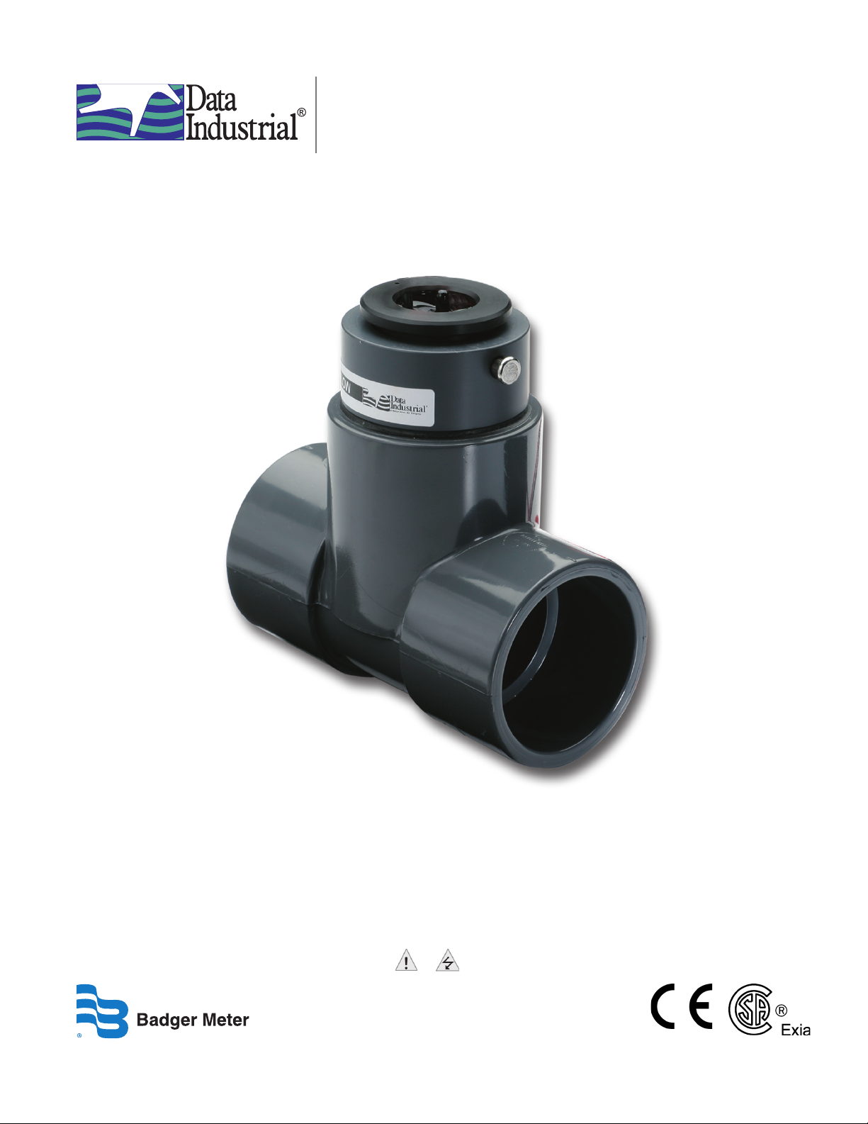
Series 228PV
Plastic Tee Type Impeller Flow Sensor
Sections of this document marked with or must be consulted for safe use of the product.
872022-EN (January 2013)
Rev. 8 Installation & Operation Manual
Page 2

Series 228PV Plastic Tee Type Impeller Flow Sensor
CONTENTS
INTRODUCTION . . . . . . . . . . . . . . . . . . . . . . . . . . . . . . . . . . . . . . . . . . . . . . . . . . . . . . . . .3
ELECTRONIC TYPES . . . . . . . . . . . . . . . . . . . . . . . . . . . . . . . . . . . . . . . . . . . . . . . . . . . . . . .3
Standard Sensor. . . . . . . . . . . . . . . . . . . . . . . . . . . . . . . . . . . . . . . . . . . . . . . . . . . . . . .3
IR Sensor . . . . . . . . . . . . . . . . . . . . . . . . . . . . . . . . . . . . . . . . . . . . . . . . . . . . . . . . . . .3
CSA Sensor . . . . . . . . . . . . . . . . . . . . . . . . . . . . . . . . . . . . . . . . . . . . . . . . . . . . . . . . . .3
Model 228PV (Formerly 220P) . . . . . . . . . . . . . . . . . . . . . . . . . . . . . . . . . . . . . . . . . . . . . .3
MECHANICAL INSTALLATION . . . . . . . . . . . . . . . . . . . . . . . . . . . . . . . . . . . . . . . . . . . . . . . .4
General Information . . . . . . . . . . . . . . . . . . . . . . . . . . . . . . . . . . . . . . . . . . . . . . . . . . . .4
Mechanical Installation Procedure . . . . . . . . . . . . . . . . . . . . . . . . . . . . . . . . . . . . . . . . . . .4
ELECTRICAL INSTALLATION . . . . . . . . . . . . . . . . . . . . . . . . . . . . . . . . . . . . . . . . . . . . . . . . .5
Electrical Installation of Standard Sensors . . . . . . . . . . . . . . . . . . . . . . . . . . . . . . . . . . . . . .5
Electrical Installation of IR Sensors . . . . . . . . . . . . . . . . . . . . . . . . . . . . . . . . . . . . . . . . . . .5
Intrinsically Safe Electrical Installation . . . . . . . . . . . . . . . . . . . . . . . . . . . . . . . . . . . . . . . . .6
DIMENSIONS . . . . . . . . . . . . . . . . . . . . . . . . . . . . . . . . . . . . . . . . . . . . . . . . . . . . . . . . . . .6
CALIBRATION. . . . . . . . . . . . . . . . . . . . . . . . . . . . . . . . . . . . . . . . . . . . . . . . . . . . . . . . . . .7
Calibration Table Columns . . . . . . . . . . . . . . . . . . . . . . . . . . . . . . . . . . . . . . . . . . . . . . . .7
Calibration Table . . . . . . . . . . . . . . . . . . . . . . . . . . . . . . . . . . . . . . . . . . . . . . . . . . . . . .7
SAMPLE INSTALLATION DRAWINGS . . . . . . . . . . . . . . . . . . . . . . . . . . . . . . . . . . . . . . . . . . . .8
IMPELLER ASSEMBLY AND SHAFT REPLACEMENT . . . . . . . . . . . . . . . . . . . . . . . . . . . . . . . . . . .9
SPECIFICATIONS . . . . . . . . . . . . . . . . . . . . . . . . . . . . . . . . . . . . . . . . . . . . . . . . . . . . . . . .10
TROUBLESHOOTING . . . . . . . . . . . . . . . . . . . . . . . . . . . . . . . . . . . . . . . . . . . . . . . . . . . . . 11
Page 2 January 2013
Page 3

Installation & Operation Manual
INTRODUCTION
Used in conjunction with any Badger Meter Impeller flow monitor or endpoint, Badger Meter non-magnetic Impeller flow
sensors provide an accurate reading of the rate of liquid flow as well as total accumulated flow. A number of sensor models
are offered, which cover applications for a wide range of pipe sizes and pressure/temperature specifications.
The flow sensors generate a frequency which is proportional to flow rate. An internal preamplifier allows the pulse signal to
travel up to 2000 feet without further amplification. Power to operate the sensor is provided by the flow monitor. The impeller
bearing assembly, shaft and o-rings are replaceable in the field.
Badger Meter Impeller flow sensors feature a closed, six-bladed impeller design, using a proprietary, non-magnetic sensing
technology. The forward-swept impeller shape provides higher, more constant torque than four-bladed impeller designs,
and is less prone to fouling by water-borne debris. The forward-curved shape, coupled with the absence of magnetic
drag, provides improved operation and repeatability, even at lower flow rates. As the liquid flow turns the impeller, a low
impedance signal is transmitted with a frequency proportional to the flow rate.
Sensors of similar type are interchangeable, so there is no need for recalibration after servicing or replacement.
ELECTRONIC TYPES
Badger Meter provides several basic sensor configurations using the same impeller element. This allows for a wide range of
applications and pipe sizes. Sensors are normally supplied with 20 feet of 2-conductor 20 AWG shielded U.L. type PTLC
105° C cable. Optional sensors designated with the prefix "IR" feature two single conductor 18 AWG solid copper wire leads
48 inches in length with U.L. Style 116666 direct burial insulation. These IR models are used in below grade applications
such as irrigation, municipal, and groundwater monitoring. All Badger Meter Series 200 sensor electrical components are
self-contained. Pressure/temperature ratings for the various models are contained in "SPECIFICATIONS" on page 10. These
models can be further described as follows.
Standard Sensor
Designed for indoor or protected area applications such as HVAC, pump control, and industrial process monitoring where the
flow rates are between 0.5…30 feet/second and temperatures are below 221° F. Standard sensors are supplied with 20 feet of
2-conductor 20 AWG shielded U.L. type PTLC 105° C cable.
IR Sensor
Designed for below grade applications such as irrigation, municipal, and groundwater monitoring where the flow rates are
between 0.5…30 feet/second and temperatures are below 180° F. IR sensors are supplied with two single-conductor, 18 AWG
solid copper wire leads 48 inches in length with U.L. Style 116666 direct burial insulation.
CSA Sensor
Designed for indoor or protected area applications where intrinsic safety is required and the flow rates are between
0.5…30 feet/second and temperatures are below 140° F. CSA sensors are supplied with 20 feet of 2-conductor 20 AWG
shielded U.L. type PTLC 105° C cable. These sensors must be used with an approved safety barrier.
Model 228PV (Formerly 220P)
These models feature a modified PVC tee with solvent weld socket end connections, and a removable, PPS or PVDF sensor
insert. Sizes of 1-1/2", 2", 3" and 4" are available.
The impeller style flow sensor described in this manual is not intended for use in safety critical applications.
Use of the device in this manner is done at the sole discretion of the customer and/or end user of the device
The impeller style flow sensor described in this manual is not intended for use in systems with flammable liquids or
gases. Additionally, the device is not intended for systems containing hazardous fluids, or fluids other than water.
The impeller style flow sensor described in this manual must be installed in accordance with all local and federal codes
or end-use standards, as applicable.
If the devices described in this manual are used in a manner not specified by the manufacturer, the protection provided
by the equipment may be impaired.
Page 3 January 2013
Page 4

Series 228PV Plastic Tee Type Impeller Flow Sensor
MECHANICAL INSTALLATION
Depressurize and vent the piping system prior to any installation or maintenance of the flow sensor.
General Information
The accuracy of flow measurement for all flow measuring devices is highly dependent on proper location of the sensor in
the piping system. Irregular flow velocity profiles caused by valves, fittings, pipe bends, or other obstructions can lead to
inaccurate overall flow rate indications, even though local flow velocity measurement may be accurate. A sensor located
in the pipe where it can be affected by air bubbles, floating debris, or sediment may not achieve full accuracy and could
be damaged. Badger Meter flow sensors are designed to operate reliably under adverse conditions, but the following
recommendations should be followed to ensure maximum system accuracy:
• Choose a location along the pipe where 10 pipe diameters upstream and 5 pipe diameters downstream of the sensor
provide no flow disturbance. Pipe bends, valves, other fittings, pipe enlargements and reductions should not be present
in this length of pipe.
• The preferred location for the sensor around the circumference of a horizontal pipe is at the 12 o'clock position. The
sensor should never be located at the bottom of the pipe, as sediment may collect there. Locations off top dead
center cause the impeller friction to increase, which may affect performance at low flow rates and increase wear. Any
circumferential location is correct for installation in vertical pipes, with rising flow preferred to reduce the effects of any
trapped air.
Mechanical Installation Procedure
1. Note the intended direction of ow as indicated by arrows on the tee. There must be free, unrestricted pipe for at least
10 diameters upstream and 5 diameters downstream of the tee.
2. Remove the clevis pin and remove the sensor from the tee.
3. Properly clean the pipe ends and tee sockets.
4. Use solvent cement to attach the pipe to the tee.
5. Reinstall the sensor in the tee as follows:
a. Align the flow arrow on the top of the sensor housing in the direction of flow.
b. Carefully press the sensor straight into the tee.
c. Install the clevis pin through the tee, the sensor, and the conduit cap, and install the cotter ring.
Page 4 January 2013
Page 5

Installation & Operation Manual
ELECTRICAL INSTALLATION
Disconnect power from flow sensor source and/or receiving device prior to any installation or maintenance
of the system.
Flow sensor source and/or receiving device must provide basic isolation from mains to insure safe operation
of the system.
Electrical Installation of Standard Sensors
1. Route the cable from the sensor to a Badger Meter ow monitor/endpoint. The cable may be extended up to 2000 feet,
using 2-conductor shielded 20 AWG or larger stranded copper wire. Be sure to leave enough exibility in the cable or
conduit to allow for future service of sensor, if necessary.
2. When connecting to a Badger Meter ow monitor/endpoint, locate the section of terminal strip on the monitor
labeled SENSOR INPUT or SENSOR. Connect the red wire to IN, SIGNAL(+) OR SIGNAL terminal and the black wire
to GND, SIGNAL(–), or COM terminal and the shield drain wire (if applicable) to SLD.
3. When interfacing with other equipment consult manufacture for input designations. The signal wave forms and power
requirements are as shown in "SPECIFICATIONS" on page 10.
Electrical Installation of IR Sensors
The sensor leads are supplied with watertight caps over the ends.
1. DO NOT remove the plastic caps from the sensor leads until ready to splice. See Application Note DAB-031 and Technical
Brief DTB-043 at www.badgermeter.com.
2. Use a twisted pair cable suitable for direct burial to connect the sensor to the endpoint, monitor, or controller. Multi-pair
telecommunication cable or direct burial cables may be used.
3. Make a watertight splice. Two-part epoxy type waterproof kits are recommended. Be sure the epoxy seals the ends of the
cable jacket.
4. Make sure the epoxy is hardened before inverting the splice or dropping it in standing water.
5. DO NOT make an underground splice unless absolutely necessary.
6. Route the cable from the sensor to a Badger Meter ow monitor/endpoint. The cable may be extended up to 2000 feet,
using 2-conductor shielded 20 AWG or larger stranded copper wire with appropriate ratings. Be sure to leave enough
exibility in the cable or conduit to allow for future service of sensor, if necessary.
7. When connecting to a Badger Meter ow monitor/endpoint, locate the section of terminal strip on the monitor
labeled SENSOR INPUT or SENSOR. Connect the red wire to IN, SIGNAL(+) OR SIGNAL terminal and the black wire
to GND, SIGNAL(–), or COM terminal and the shield drain wire (if applicable) to SLD.
8. When interfacing with other equipment, the signal wave forms and power requirements are as shown in
"SPECIFICATIONS" on page 10.
Page 5 January 2013
Page 6
Series 228PV Plastic Tee Type Impeller Flow Sensor
B
C
B
C
Intrinsically Safe Electrical Installation
The Series 200 Sensor is approved, as an entity, as intrinsically safe when installed in conformance with Badger Meter
installation drawings 06-480-001 or 06-480-002 (sample shown in "SAMPLE INSTALLATION DRAWINGS" on page 8) as
specified on the blue label identifying an intrinsically safe sensor.
Entity approval implies that only the sensor is approved as intrinsically safe. Unless power supplies, equipment, and
instruments connected to the sensor are each rated either explosion-proof or intrinsically safe, these devices cannot be
installed in a hazardous area. The referenced installation drawing shows such apparatus located in a non-hazardous location.
Proper interfacing between the hazardous and non-hazardous areas must be provided. It is of absolute importance that
this interface be constructed and that all wiring be performed by qualified contractors. To ensure the intrinsic safety of the
installation, the connection of the intrinsically safe sensor to instruments and or power supplies must take place using an
approved intrinsically safe barrier located in a non-hazardous area. These barriers, listed below, are readily available from
various suppliers.
Manufacturer Barrier
Crouse-Hinds Spec 504 Cat No. SB19140M0715
Measurement Technology Ltd. MTL 715+ 15 V
R Stahl Intrinspak 9001/01-158-150-101
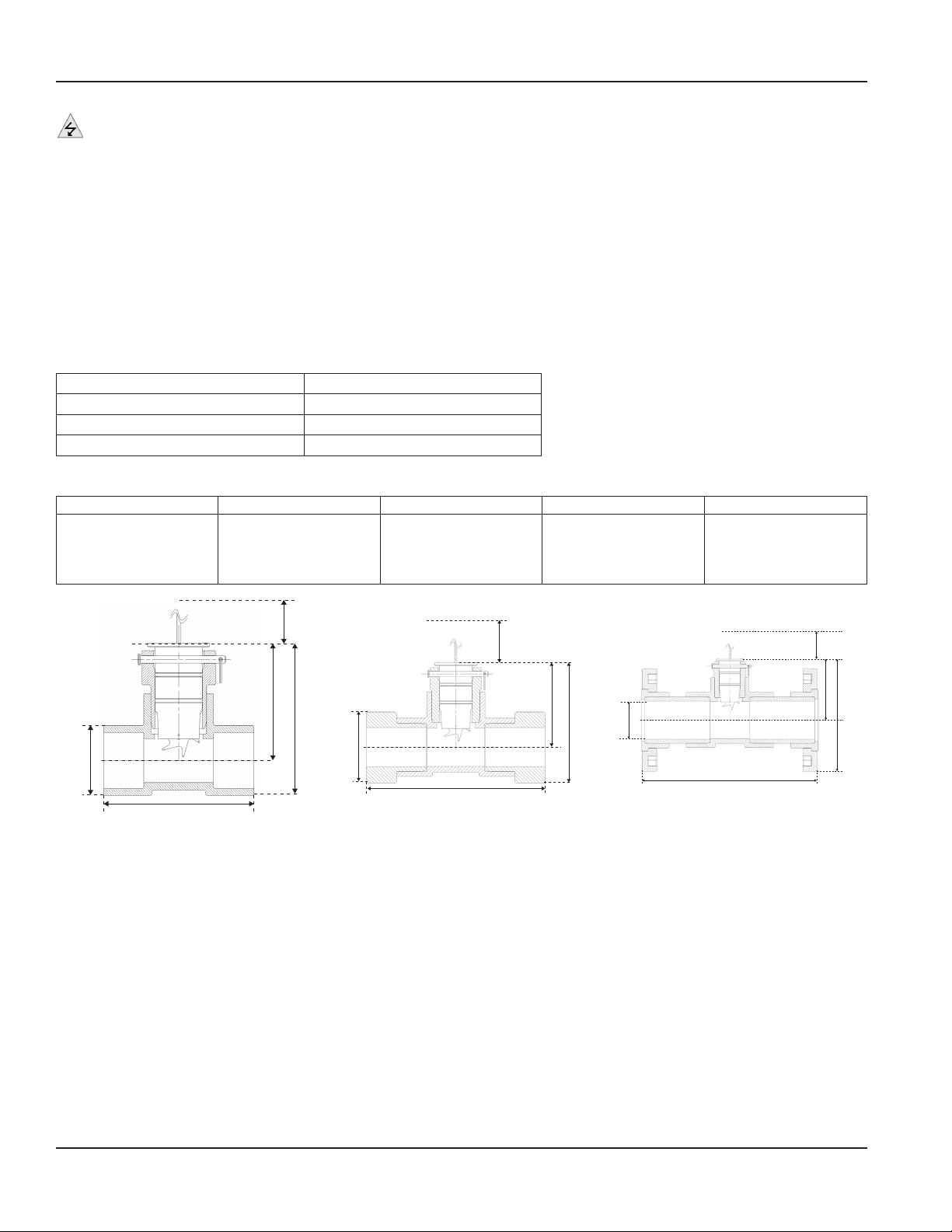
DIMENSIONS
Series No. Complete 228PV15XX-XXX 228PV2XXX-XXXX 228PV3XXX-XXXX 228PV4XXX-XXXX
A5
B5
C2
D3
E5
5.0" (127 mm)
5.16" (131 mm)
2.38" (60 mm)
3.97" (101 mm)
5.0" (127 mm)
5.63" (143 mm)
5.64" (143 mm)
2.88" (73 mm)
4.20" (107 mm)
5.0" (127 mm)
6.50" (165 mm)
6.83" (173 mm)
4.23" (107 mm)
4.68" (119 mm)
5.0" (127 mm)
7.38" (187 mm)
6.83" (199 mm)
5.38" (137 mm)
5.10" (130 mm)
5.0" (127 mm)
E
E
D
A
A
No Fittings
BSP Fittings
D
C
Figure 1: A = Overall Length; B = Overall Height; C = Diameter;
D = Center of Tube to Top Height; E = Minimum Clearance for Sensor Removal
E
D
B
A
Flanged
Page 6 January 2013
Page 7

Installation & Operation Manual
Freq=
Gpm
K
- offse
t
CALIBRATION
Badger Meter Impeller sensors use unique K and offset numbers for calibration. These numbers are derived from calibration
runs using NIST traceable instruments. Using both a K and an Offset number provides higher accuracy than using a K factor
alone. The K and Offset numbers for each tee configuration are listed in the "Calibration Table" below.
Calibration Table Columns
The table below provides calibration and operation data for Badger Meter Plastic Tee Sensors 1-1/2" to 4".
Column 1 Sensor Model Number
Columns 2 and 3 The K value and Offset values to use in our frequency equation:
This equation describes the frequency of the output signal of all Badger Meter flow sensors. By
substituting the appropriate K and Offset values from the table, the sensor’s output frequency can be
calculated for each pipe size. This information is required when calibrating an output board or when
using the raw sensor data as direct output to interface with a device that is not a Badger Meter product.
Column 4 This column indicates the suggested flow range of each tee sensor. Badger Meter sensors will operate
both above and below the indicated flow rates. However, good design practice dictates the use of this
range for best performance.
Sensors should be sized for flow rather than pipe size. To prevent disturbances to the flow profile
always connect the sensor tee to pipe nipples measuring at least 10 pipe diameters in length on the up
stream (supply) side and at least 5 pipe diameters in length on the downstream (delivery) side before
making the transition in pipe size. If a lesser flow rate is chosen, an insufficient span exists for the proper
operation of these circuits. This can result in excessive ripple and fluctuations in signal, which can
adversely affect system performance.
Calibration Table
Model for K Offset Suggested Operating
228PV15xx-xxxx
228PV20xx-xxxx
228PV30xx-xxxx
228PV40xx-xxxx
1.697
2.8429
8.309
13.74283
-0.316
0.1435
0.227
0.23707
Range (gpm)
5…100
10…200
20…300
40…500
Page 7 January 2013
Page 8

Series 228PV Plastic Tee Type Impeller Flow Sensor
SAMPLE INSTALLATION DRAWINGS
Figure 2: Sample Installation Drawings
Page 8 January 2013
Page 9

Installation & Operation Manual
IMPELLER ASSEMBLY AND SHAFT REPLACEMENT
If you are replacing an existing Badger Meter sensor and have already calibrated your flow monitor/endpoint, no calibration
changes are necessary. For installation of a new flow monitor or for relocation of a sensor in a new pipe size, please refer to
the calibration instructions in flow monitor manual.
1. Depressurize and vent pipe and remove power from the installation from which sensor is to be removed.
2. Remove the clevis pin.
3. Remove the sensor from the tee.
4. Note the impeller blade orientation relative to ow arrows. In order to maintain proper calibration, the impeller will have
to be reinstalled in the same manner with the impeller blades pointing toward the ow source as indicated by the
ow arrows.
5. To remove the old impeller blade assembly, push the old shaft out of the sleeve with the new shaft (or small diameter rod)
just far enough to grab the end with a pair of pliers and pull the shaft completely out. The impeller assembly will now be
free, and will drop out.
6. Inspect the shaft and bearings for wear, and replace as necessary.
7. See Figure 3 below. To reinstall, position the impeller in the cavity oriented as in Step 4 so that the impeller blades
point into the ow direction. The ow direction arrow on the top of the sensor housing should point downstream with
the impeller blades pointing upstream.
8. Carefully push the shaft through the housing and impeller, taking care not to damage bearings. Make sure that the shaft is
inserted far enough so that it clears the housing on each side of the impeller housing.
OTE:N If shaft is not carefully installed, the bearing can be deformed, preventing free rotation.
9. Inspect the O-rings for damage and replace as necessary. Clean the O-rings and the sleeve and relubricate with silicone
grease from the packet provided, or use some other acceptable lubricant.
10. Install the sensor into the tee so the ow arrow points in the direction of the actual ow.
11. Install or replace the clevis pin.
This completes the replacement procedure. The system may now be repressurized and tested.
NOTE DIRECTION OF ARROW
USE PLIERS HERE
NOTE DIRECTION OF
IMPELLER
USE METAL PIN TO
REMOVE CERAMIC SHAFT
Figure 3: Impeller Assembly and Shaft
Page 9 January 2013
Page 10
Series 228PV Plastic Tee Type Impeller Flow Sensor
100
560
Pressure (psi)
SPECIFICATIONS
Wetted Materials (except tees) See "Ordering Matrix" in Technical Brief for material specifics.
Tee for 228PV Schedule 80 PVC per ASTM D-2462 and D-2467, Virgin, unplasticized PVC resin, Type 1 cell
classification 12454-B. Fittings and solvent carry approval for potable water by NSF and IAMPO.
Pressure/Temperature
Ratings
(DO NOT EXCEED)
Rated Temperature
(DO NOT EXCEED)
Recommended Design
Flow Range
Accuracy ± 1.0% of full scale over recommended design flow range
Repeatability ± 0.3% of full scale over recommended design flow range
Linearity ± 0.2% of full scale over recommended design flow range
Transducer Excitation • 8…35V DC max. input, source limited to 100 mA
Output Frequency 3.2…200 Hz
Output Pulse Width 5 msec ±25%
Environmental • IP 68 / NEMA 4X
Electrical Cable for Standard
Sensor Electronics
Electrical Cable for IR Sensor
Electronics
Depends on hardware configurations.
80
60
40
20
0
02
Temperature (°C)
Operating: 35…110° F
Storage 14…110° F
0.5…30 ft/sec
• Quiescent current 600 uA @ 8…35V DC max.
• Quiescent voltage (Vhigh=Supply Voltage–(600 uA*Supply impedance))
• ON State (Vlow) Max. 1.2V DC @ 40 mA current limit (15 Ω + 0.7V DC)
• Suitable for pollution degree 4 environments
• Suitable for outdoor use above grade, IR version below grade
• Suitable for use in 100% humidity
20 feet of 2-conductor AWG 20 with AWG 22 drain wire shielded UL type PTLC wire provided for
connection to display or endpoint unit. Rated to 105° C. May be extended to a maximum of 2000
feet with similar cable and insulation appropriate for application.
48 inches of UL Style 116666 copper solid AWG 18 wire w/direct burial insulation. Rated to 105° C.
Page 10 January 2013
Page 11

Installation & Operation Manual
TROUBLESHOOTING
The Series 200 flow sensors are active devices that are most easily tested at the connection point of the controller to which
they are connected.
The sensor is essentially a 15 Ohm switch with a 600 uA leakage current. With no flow running (the impeller not turning), the
sensor will appear to the controller input as a small current load. When the impeller is turning, it appears a quick series of
5 ms short circuits.
Before trying to troubleshoot, confirm that the flow rates are well above the minimum recommended flow rates. This will
usually purge any air out of the line, and will ensure that the impeller is actually spinning in the flow.
If the controller is not recognizing a flow input from this sensor, test the controller itself by disconnecting the flow sensor, and
very quickly and repeatedly short together the two terminals that the flow sensor was connected to. The controller should
report some flow. If it does not, the problem is in the controller, and not the flow sensor or wiring to it.
If the controller appears to be working, while the sensor is still disconnected measure the open circuit voltage on the
controller's sensor input terminals.
This voltage must be between 8…24V DC for the sensor to operate.
If the voltage is acceptable, reconnect the flow sensor and re-measure. Depending on the age of the flow sensor, the voltage
should drop slightly. Current production sensors will drop about a volt or so, sensors manufactured prior to 2001 will drop to
about 8V DC. If no drop is observed, the sensor is wired backwards, or there is a break in a wire or splice, or the sensor is open
internally. If the voltage drops to near zero, there is either a short in the wiring or splice or the sensor is shorted internally. If
the voltage drops below 7V—but not to levels indicating a short—there is most likely moisture penetration or corrosion in
the wiring or in the sensor itself.
If the electrical tests all look normal, you will have to drain the pipe, remove the sensing element, and spin the impeller
by hand.
When spun by hand, the impeller should spin freely and slide smoothly to a stop, with no evidence of damage or wear on any
of the surfaces, and the controller should recognize the signal and report a flow. If it does not, the sensor electronics are no
longer operational and must be replaced.
If the impeller/bearing is simply worn or damaged, and signal is observed when the impeller is forced to turn, then an
impeller repair kit can be installed as described in "IMPELLER ASSEMBLY AND SHAFT REPLACEMENT" on page 9.
Page 11 January 2013
Page 12

Data Industrial is a registered trademark of Badger Meter, Inc. Other trademarks appearing in this document are the property of their respective entities.
Due to continuous research, product improvements and enhancements, Badger Meter reserves the right to change product or system specications without notice, except to the extent an outstanding
contractual obligation exists. © 2013 Badger Meter, Inc. All rights reserved.
www.badgermeter.com
The Americas | Badger Meter | 4545 West Brown Deer Rd | PO Box 245036 | Milwaukee, WI 53224-9536 | 800-876-3837 | 414-355-0400
México | Badger Meter de las Americas, S.A. de C.V. | Pedro Luis Ogazón N°32 | Esq. Angelina N°24 | Colonia Guadalupe Inn | CP 01050 | México, DF | México | +52-55-5662-0882
Europe, Middle East and Africa | Badger Meter Europa GmbH | Nurtinger Str 76 | 72639 Neuffen | Germany | +49-7025-9208-0
Czech Republic | Badger Meter Czech Republic s.r.o. | Maříkova 2082/26 | 621 00 Brno, C zech Republic | +420-5-41420411
Slovakia | Badger Meter Slovakia s.r.o. | Racianska 109/B | 831 02 Bratislava, Slovakia | +421-2-44 63 83 01
Asia Pacific | Badger Meter | 80 Marine Parade Rd | 21-04 Parkway Parade | Singapore 449269 | +65-63464836
China | Badger Meter | Rm 501, N° 11 Longyue Apartment | N° 180 Longjin Rd, Jiuting Songjiang District | Shanghai, China | 201615 | +86-21-5763 5412
 Loading...