

Page 1
Electronic Scalable Transmitters
Models PFT-1E & PFT-4E
OVERVIEW
The models PFT-1E and PFT-4E are electronic scalable pulse
transmitters with AC/DC inputs and outputs. The model
PFT-1E combines with the disc and OP meter lines while the
model PFT-4E is used with the Industrial turbo meter line.
These electronic transmitters can be scaled to almost any
pulse rate, allowing recalibration by resetting the scale
factor with four switches. The PFT-1E transmitter can be
calibrated for use with different size meters simply by
re-setting the switches.
OPERATION
The flow of fluid through any of the meters results in
movement of the meter measuring element, which rotates
an internal 4-pole magnet. The poles of the magnet are
sensed by a magnetoresistive pickup that produces four
pulses for each revolution of the magnet. These signals are
sent to the electronic board where they are conditioned and
scaled to the desired unit of flow (for example, one pulse
per ounce, per gallon, and so on). The meter factor, which
is the number of revolutions of the measuring element
per unit of measure, rarely coincides with the desired
application requirements and has to be modified or scaled
to standard engineering units. This scaled pulse is then sent
to secondary equipment such as a controller or remote
totalizer in the form of a switched AC voltage or a DC current
sinking pulse (open collector NPN transistor).
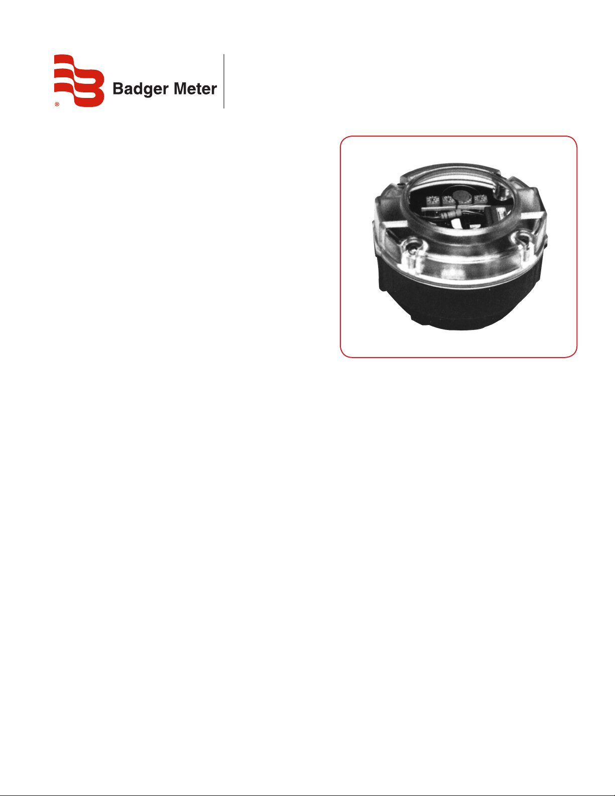
PFT-1E Transmitter
FEATURES
• Sensor will withstand fluid temperatures to 250° F
• Solid-state circuitry for long life
• Fast calibration with (4) switches; change gears
are eliminated
• LED indicator for visual pulse detection
APPLICATIONS
Designed for totalizing, rate calculation or batching through
direct input into a totalizer, pre-set counter or process
controller that does not have scaling capabilities.
XMT-DS-00837-EN-15 (January 2018)
• Optically isolated outputs prevent false counts due to
line noise
• Field retrofit available
• Rugged, high impact resistant housing
• Corrosion proof protection
• Water tight - NEMA 4X Rating
• Remote mounting available
Product Data Sheet
Page 2

Transmitter Specications
TRANSMITTER SPECIFICATIONS
Housing Material High impact, reinforced
Nylon
Mounting Bayonet type with set
screw, 360° orientation
Connections Two 1/2” NPT threaded
conduit ports
Protection NEMA 4X (water tight &
corrosion proof)
Operation Sensor Magnetoresistive sensor
Scaling & Calibration (4) switches
Operating
Temperatures
Electrical DC Input Power 12…24V DC
DC Output Opto-Isolated open
Transistor Rating 50 mA @ 24 VDC
AC Input Power 115 VAC ± 15%
AC Output Opto-isolated Zero
Triac Rating 130 V RMS @ 500 mA
Scaling Resolution 0.0001 to 0.9999
Max. Pulse
Resolution
(Limit AC pulse output to 10 pulses per second due to
electrical characteristics of Triac.)
Transmitter Selection Chart
Meter Type PFT-1E PFT-4E
RCDL X
IND. TURBO X
OP X
Scaler Board: – 4…185° F
Sensor: – 4…250° F
collector NPN transistor
Crossing Triac
See chart
SCALE FACTOR CALCULATION
Pulses per Gallon Wanted
Scale Factor = ---------------------------------------------- Transmitter Output in Pulses per Gallon
See the chart below for the average number of output
pulses per gallon for your particular meter. For more precise
calculations, use the information on the transmitter data
plate when figuring scale factors.
Example
Compute the scale factor for a 3” turbo meter. (You want to
measure the flow to the nearest 0.1 gallon.)
Scale factor = 10 / 24.80 = 0.4032
Enter 0.4032 on the scaling switches of the transmitter to
read the meter flow to the nearest 0.1 of a gallon.
Meter Size Pulse/Oz. Pulse/Gal.
RCDL-25
RCDL-35
RCDL-40
RCDL-70
RCDL-120
RCDL-170
IND. TURBO
IND. TURBO
IND. TURBO
IND. TURBO
OP
OP
OP
5/8
3/4
1
1
1-1/2
2
2
3
4
6
1/2
1
2
1.550
0.989
0.702
0.366
0.186
0.114
0.271
0.194
0.040
0.017
1.742
0.599
0.161
198.340
126.671
89.781
46.752
23.867
14.565
34.720
24.800
5.120
2.160
222.960
76.640
20.560
Shown with pin# on new board for same function
New Board Wire Color/Old Board
Pin 1 Blue (Blue/Brown)
Pin 2 Black (White/Black)
Pin 3 White (White/Black)
Pin 4 Brown (Blue/Brown)
Pin 5 Orange (Orange/Brown)
Pin 6 Brown (Orange/Brown)
Pin 7 Black (Black/Red)
Pin 8 Red (Black/Red)
123
2
1
Page 2 January 2018XMT-DS-00837-EN-15
Conversion Chart
(Wire colors from old style board)
Page 3

Scaling Switch Settings
SCALING SWITCH SETTINGS
For units with PC boards that have DIP switches, use the following guide to set the scale factor:
To set the switches, move the white switches to the UP position. The values of the different switch combinations are
shown below.
OTE:N Switch positions are represented by the
black squares in this graphic.
Units ordered prior to 02/01/2018 will
NOT produce pulses.
Units ordered after 02/01/2018 will
pulse using a value of “9”.
Example
This example shows the unit set at 0.4032.
CIRCUIT BOARD
Page 3 January 2018 XMT-DS-00837-EN-15
Page 4

Electronic Scalable Transmitters, Models PFT-1E & PFT-4E
Control. Manage. Optimize.
Trademarks appearing in this document are the property of their respective entities. Due to continuous research, product improvements and enhancements, Badger Meter reserves
the right to change product or system specications without notice, except to the extent an outstanding contractual obligation exists. © 2018 Badger Meter, Inc. All rights reserved.
www.badgermeter.com
The Americas | Badger Meter | 4545 West Brown Deer Rd | PO Box 245036 | Milwaukee, WI 53224-9536 | 800-876-3837 | 414-355-0400
México | Badger Meter de las Americas, S.A. de C.V. | Pedro Luis Ogazón N°32 | Esq. Angelina N°24 | Colonia Guadalupe Inn | CP 01050 | México, DF | México | +52-55-5662-0882
Europe, Eastern Europe Branch Oce (for Poland, Latvia, Lithuania, Estonia, Ukraine, Belarus) | Badger Meter Europe | ul. Korfantego 6 | 44-193 Knurów | Poland | +48-32-236-8787
Europe, Middle East and Africa | Badger Meter Europa GmbH | Nurtinger Str 76 | 72639 Neuen | Germany | +49-7025-9208-0
Europe, Middle East Branch Oce | Badger Meter Europe | PO Box 341442 | Dubai Silicon Oasis, Head Quarter Building, Wing C, Oce #C209 | Dubai / UAE | +971-4-371 2503
Slovakia | Badger Meter Slovakia s.r.o. | Racianska 109/B | 831 02 Bratislava, Slovakia | +421-2-44 63 83 01
Asia Pacic | Badger Meter | 80 Marine Parade Rd | 21-06 Parkway Parade | Singapore 449269 | +65-63464836
China | Badger Meter | 7-1202 | 99 Hangzhong Road | Minhang District | Shanghai | China 201101 | +86-21-5763 5412
Switzerland | Badger Meter Swiss AG | Mittelholzerstrasse 8 | 3006 Bern | Switzerland | +41-31-932 01 11 Legacy Document Number: ITB-068-10 543406-008
 Loading...