

Page 1

Model PC100
Process Controller
Installation &
Operation Manual
IMPORTANT !!!! Read this manual before
attempting any installation, wiring or operation.
SERVICE INFORMATION
(FILE MANUAL FOR FUTURE REFERENCE AND SERVICE)
Serial Number Date Installed / /
Service Line Operator
IOM-036-07
BadgerMeter,Inc.
®
Part No. 53400-036
3-09
Page 2

2
Page 3

SCOPE OF THIS MANUAL
OPERATION OF THE PC100
The sections in this manual have been arranged in such
a way that you can, step-by-step, install, program, operate
and, when required, troubleshoot the instrument.
The PC100 has many features. However, for normal
operation, you need to be concerned with only a few of them.
The MAIN MENU shows most of the procedures and
functions that are normally implemented to properly operate the unit.
The OPTIONAL MENU lists procedures or functions that
can be implemented but are not required.
The COMMUNICATIONS MENU should be referenced only
if you are connecting the PC100 to a serial printer or to a
computer or process controller.
MAIN MENU OPTIONAL MENU
- Unpack and install the PC100 ................................. 4
- Wiring procedures ................................................... 4
- Assembly and installation of PC100XP .................... 5
- Operation and programming of all functions .......... 10
- Troubleshooting and reprogramming ...................... 18
WIRING
- Connecting pulse transmitters to the PC100 .......... 6
- Connecting single stage valves, two stage valves,
pumps, motors, and alarms ...................................... 7
- Connecting the AC or DC power .............................. 6
PROGRAMMING
- Scale factor to count in gallons, liters, etc. ............ 13
- Decimal point to show fractions ............................. 12
- Count from zero up or from batch down to zero ..... 12
- End of batch to stay at zero or
to reset to batch size .............................................. 13
- Programming the batch size .................................... 15
- Programming the prewarn or
first valve stage signal ........................................... 15
DISPLAYS
- Ten digit totalizer .................................................... 10
- Instantaneous flow rate ........................................... 10
COMMUNICATIONS MENU
- Wiring a serial printer to the PC100 ....................... 9
- Wiring to host computer or process controller ...... 9
- Wiring the remote Print command .......................... 9
- Selecting communications or totalizer output ...... 17
- Programming the BAUD rate ................................... 17
- Assigning and ID number to each PC100 ............... 17
- Selecting information to be sent to the printer ...... 17
- Selecting automatic print on STOP and/or START .. 17
- Selecting line print delay to match printer used .... 17
- Enabling “on line” message to be printed after
a failure or power down ......................................... 17
The PC100 is a batch controller. It will accept a signal
input from the transmitter, scale it to the desired unit of
measure, and send a signal to operate a valve, pump, alarm,
motor, etc.
In addition, it can count the number of batches, totalize
inventory, indicate rate of flow, provide high and low flow
alarms and communicate with printers and computers.
Other features include “slow valve closing” compensation, batch size limit, fail safe shutdown, and programmable
function disabling.
After all items of the MAIN MENU have been implemented,
select and program those in the OPTIONAL and COMMUNICATIONS MENUS.
THE FOLLOWING FUNCTIONS ARE OPTIONAL
TO THE OPERATION OF THE UNIT.
OPTIONAL WIRING
- Connecting remote controls to START, STOP,
RESUME, RESET COUNTERS and PRINT ............. 8
- Connecting a printer ............................................... 9
- Connecting to host computer/process controller .... 9
- Connecting alarms or remote totalizers .................. 8
OPTIONAL PROGRAMMING
- Display FLOW RATE instead of BATCH COUNT ..... 13
- LIMIT the batch size that can be programmed ..... 15
- AUTORECYCLE to repeat batches automatically ... 15
- AUTOADJUST, to compensate for valve overrun .... 15
- CYCLE preset, to stop after a set no. of batches ..... 15
- FAIL-SAFE will stop batch if pulses not sensed ..... 12
- HI and LOW FLOW rate alarm setpoints ................ 16
- FLOW ALARM on/off ................................................ 16
- PREWARN signal duration ...................................... 15
- DISABLE any combination of functions ................. 14
- DISABLE START, STOP, RESUME .......................... 14
- Programming outputs for flow alarms or
scaled pulse output or cycle count output ........... 12
- Resetting the totalizer ............................................ 16
3
Page 4
HOW TO UNPACK, ASSEMBLE
AND INSTALL THE PC100
HOW TO WIRE
THE PC100
Note: If damage to the shipping container is obvious,
request that the carrier be present when the product is
unpacked. All claims for equipment damage during transit
are the sole responsibility of the recepient.
UNPACKING
After carefully unpacking the unit, check
for any visible sign of damage. If found,
notify the carrier for insurance purposes
and call the factory for possible replacement. Keep all
packing material in the event that the unit must be return
to the factory.
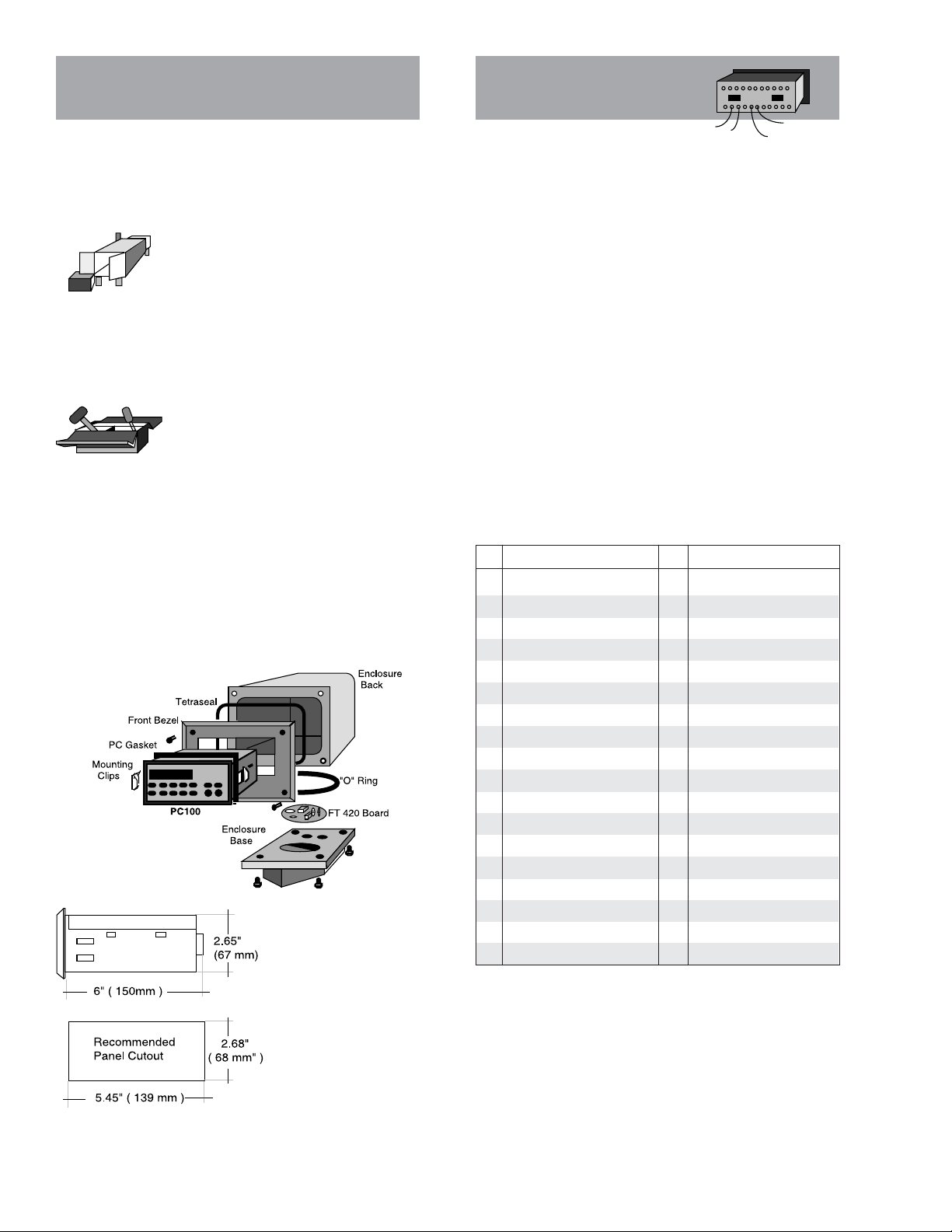
ASSEMBLY
The PC100 can be installed on the flowmeter, on a wall or shelf, or in an instrumentation panel. The picture below shows
the exploded view of a meter or wall
mounted unit. In this configuration, the
PC100 is shipped separately and must be installed as shown.
(See wiring diagrams for proper transmitter signal connections.)
The basic unit is equipped for panel mount. To install:
1- Measure and cut mounting hole to the dimensions shown.
2- Install gasket around the mounting bezel.
3- Pass the unit through the front panel cutout.
4- Secure the unit to the panel with the mounting clips.
5- Complete wiring and reassemble unit.
Note: Operating temperature is 32° F to 130° F (0°
to 55° C) with a maximum
humidity of 85% non-condensing.
Always select a mounting location with proper
ventilation and environment protection.
The rear panel of the PC100 controller contains 36 screw
terminals for connecting #28 to #18 gauge insulated wire
(#18 gauge stranded twisted pair shielded cable is recommended.)
A wire stripper and a small screwdriver are the only tools
required. Detailed diagrams in this section illustrate the
proper wiring procedures for all standard and optional
functions.
At installation, be sure to comply with the following
requirements:
• Disconnect power to the unit before attempting any
connection or service to the unit
• Avoid using machine power service for AC power. When
possible, a dedicated or lighting circuit is recommended
• Do not bundle or route signal lines with power lines
• Keep all lines as short as possible
• Use twisted pair shielded wire for all input wiring
• Observe all applicable local electrical codes
Terminal Identification List
No Function No Function
1 Reset Cycle Counter 19 DC Power Input
2 Resume Remote Input 20 15 VDC Power Output
3 Stop Remote Input 21 DC Common
4 Reset Totalizer 22 Relay K1 Contact NC
5 Transistor Output 1 23 Relay K1 Contact C
6 Transistor Output 2 24 Relay K1 Contact NO
7 Transistor Output 3 25 AC Power Input
8 Transistor Output 1A 26 AC Power Input
9 Transistor Output 2A 27 AC Power Input
10 Transmitter Input 2 28 AC Power Input
11 Low Frequency 2 29 Relay K2 Contact NC
12 DC Common 30 Relay K2 Contact C
13 Low Frequency 1 31 Relay K2 Contact NO
14 Transmitter Input 1 32 Chassis Ground
15 Function Inhibit 33 Serial Data Input (-)
16 Print Command 34 Serial Data Input (+)
17 Start Command 35 Serial Data Output (+)
18 Pulse Input Doubler 36 Serial Data Output(-)
CAUTION: To prevent accidents, power connection should
Note: K1 relay coil jumper is factory wired to terminal 8.
K2 relay coil jumper is factory wired to terminal 9. At the
end of the batch, transistor outputs 2 and 2A (terminals 6
and 9) are energized. At prewarn, terminal outputs 1 and 1A
(terminals 5 and 8) are energized.
4
Page 5

HOW TO ASSEMBLE AND
INSTALL THE PC100XP
This section deals with the procedures and recommendations on how to install Badger’s PC100XP electronic
batch controller in hazardous locations.
Except for the assembly and installation procedures, all
other instructions are identical to the standard PC100 and
should be referred to in this manual.
DESCRIPTION
The PC100XP is a standard batch controller mounted in
an explosion proof enclosure. The enclosure is FM approved for CLASS 1, DIVISION 1, GROUPS C & D and CLASS
II, GROUPS E, F & G environments. The enclosure complys
with CSA and UL standards. It is also rated for NEMA 3, 4,
7 & 9 service (watertight).
OPERATION
The operation of the PC100XP is identical to that of the
PC100 controller. On the PC100XP model, programming of
functions and control commands is done mechanically
through explosion proof push buttons.
Note: To prevent accidental or unauthorized tampering,
deactivate all programming or command functions (except
for those required during production operation) using function #41.
UNPACKING
The PC100XP is shipped from the factory disassembled.
The standard PC100 and the XP enclosure are shipped
separately to facilitate installation and wiring.
ASSEMBLY
ALWAYS FOLLOW LOCAL CODES AND MANUFACTURER’S INSTRUCTIONS WHEN INSTALLING THIS AND
OTHER TYPES OF EQUIPMENT IN HAZARDOUS ENVIRONMENTS.
Note: Operating temperature is 32° F to 130° F with a
maximum humidity of 85% non-condensing. Select a mounting location with proper ventilation.
Warning: To prevent the danger of electrical shock or
explosion, turn off the power in any circuits that may
introduce power to the wiring during the installation of this
controller.
STEP-BY-STEP INSTALLATION
The following step-by-step installation instructions
should be regarded only as a guideline for proper installation. Local codes or practices may require additional
functions to be performed in order to assure safety of
installation and operation.
1. Using a 1/4" allen wrench, remove the cover bolts from
the front cover. Carefully place the cover over a level
surface.
2. Unscrew the mounting plate screws and remove the
Mounting plate.
3. Open the PC100 carton and remove the unit. Use the
enclosed mounting clips to mount the PC100 to the
mounting plate.
4. Using the bottom and/or side tapped holes, mount the
XP housing onto a firm platform, cabinet or the wall.
Upon completion of all wiring, tightly close all enclo-
sures within the system.
Before applying power to the system:
• All electrical connections must be secure.
• All seals must be properly poured and completely
cured and their seal fittings tightly closed.
• All joints in the conduit run must be tight.
• All enclosures in the system must be tightly closed.
Apply power to the controller and test operation in a
manner that is suitable for the particular application. Exercise extreme caution!
For technical assistance during or after installation,
please call our sales department or contact the Badger
Meter representative in your area.
5
Page 6

HOW TO CONNECT THE PC100
MSE5XP
TO AC OR DC POWER
HOW TO CONNECT SIGNAL
TRANSMITTERS TO THE PC100
CAUTION: To prevent accidents, power connection should
be made only after all other connections have been completed.
The PC100 is a microprocessor controller. It is important
that the power supply be as "clean" as possible. Avoid using
power lines that feed heavy loads such as pumps, motors, etc.
If dedicated lines are not available, a filtering or isolation
system might be required.
It is recommended that fuse protection be installed. Use
a 2/10th amp slow blow fuse on 120 VAC and a 1/10th amp slow
blow fuse on 240 VAC supply.
The following diagrams show how to wire most of the flow
transmitters supplied with Badger Meter flow meters.
Connection of transmitters from other manufacturers is
similar. This section deals with pulse outputs generated by
reed switches and by current sinking open collector transistors, the most common types of outputs found in flow meter
pulse transmitters.
Note: A jumper between terminals #12 and #18 will double
the transmitter output frequency.
WARNING!! Transmitter lines carry very low power signals and are sensitive to external noise. Always use shielded
cable and keep AC power lines away from signal lines. Do not
bundle or route these together since this may cause erratic
operation of the PC100. DO NOT ground the cable shield at
the transmitter end.
• REED SWITCH TRANSMITTERS (Type A)
Reed switch transmitters close a contact to DC common.
Switches of this type have outputs of less than 150 HZ and
generate contact bounce.
Therefore, installation of a jumper between terminals
#12 and #13 is required. This effectively filters the unwanted
extra closures caused by contact bounce. (Jumper terminals #11 and #12 if using transmitter input 2 on terminal
#10).
Typical US electrical code identifies the black wire as the
hot or hi lead, the white wire as the low or neutral lead, and
the green wire as the chassis ground lead.
For 240 VAC operation:
USA Europe
Black Blue
Red Brown
Green Green/yellow
DC supply for mobile operation or as a backup supply can
be done with a battery or other DC supply of 11-16 VDC/1amp.
Note: DC supply will not be available from terminal #20
when powering the unit with DC current.
• EPT1XP & PEPT1 (TYPE B)
These models require that a special current regulator
supplied with the transmitter be installed exactly as shown.
Reversing the polarity will damage the transmitter. No
pulses will be detected without it.
EPT-1XP
6
Page 7

• OPEN COLLECTOR OUTPUT (Type C)
PFT2E, PFT3E, FT1E transmitters and meter mount
PC100 sensors generate output signals from a current
sinking NPN (open collector) transistor. The PC100 provides the necessary DC power from terminal #20 only when
on AC main power.
• FT420XP (TYPE D)
This transmitter has dual output, a 4-20 mA analog signal,
and an unscaled open collector transistor pulse.
HOW TO CONNECT VALVES,
MOTORS, PUMPS AND ALARMS
The following diagrams show how to wire the (2) relay
outputs of the PC100. Each relay has a single set of form C
contacts (one normally open and one normally closed).
Relay outputs are typically used to energize or de-energize
solenoids in valves, motors, pumps, and alarms.
CAUTION: Because the relays may be switching high
power devices, DO NOT use the PC100 AC power supply to
power valves or pumps. This might generate electrical noise
and could damage the processor.
TYPICAL APPLICATIONS
• SINGLE STAGE VALVE CONNECTION
Always use Relay K2 when connecting to a single stage
valve. At the preset batch point the relay will be de-energized, cutting power to the valve solenoid and causing the
valve to shut off.
FT420XP
• PFT3 (TYPE E)
This transmitter consists of a Reed switch sensor which
generates contact bounce. It is similar in operating to a Type
A-2 transmitter.
Therefore, installation of a jumper between terminals
#12 and #13 is required. This effectively filters the unwanted
extra closures caused by contact bounce. (Jumper terminals #11 and #12 if using transmitter input 2 on terminal
#10).
• MAIN PUMP CONNECTION
Relay K2 is connected to the pump motor to energize at
the beginning of the batch and de-energize at the end. If
used with a one stage valve, use Relay K1 and program
prewarn to zero (0). (See page15.)
• TWO STAGE VALVE CONNECTION
Relay K1 is connected to the first stage valve solenoid to
partially close the valve and Relay K2 is connected to the
second stage for final valve shutdown.
OPTIONAL APPLICATIONS
• FEED PUMP CONNECTION
Relay K1 can be connected to a feed pump to inject or add
fluids to the main batch on a preset time basis. (Refer to F32)
• HI AND/OR LOW FLOW ALARM
Relay K1 can be connected to an alarm to provide a
permanent or temporary warning signal when a low or hi
flow preset point has been exceeded. To do this, move wire
from terminal #8 and connect to terminal #7. See how to
program the hi and low flow set points on page 14.
7
Page 8

• RELAY PULSE OUTPUT
Relay K1 can also be used as a dry switch closure pulse
output to operate devices such as remote counters or batch
control panels (output frequency not to exceed 5 HZ.) To do
this, move wire from terminal #8 to terminal #7.
See how to program pulse output duration on page 13.
Scaled Pulse Output: Generally used to drive an elec-
tronic remote counter or totalizer, or to interface with
remote controllers. When using output in this manner you
can select a pulse duration of 1 ms to 99 ms depending on the
output frequency and the sensitivity of the receiving device.
End of Batch Signal: Can be used to totalize batches or
cycle runs during a period of time, or to cascade several
PC100s, so that one PC100 can start when the other finishes.
This signal duration is adjustable.
• FLOW ALARMS
Used with a low powered piezoelectric or similar sounding
device. It is energized when either the hi or the low flow
setpoints have been exceeded and can be programmed to
remain active until the end of the batch or to reset if the flow
returns within preset limits.
Note: Transistor outputs #1 and #1A are de-energized the
same as Relay K1, and transistor outputs #2 and #2A, the
same as Relay K2. Therefore, these outputs can be used to
drive external relays or other devices simultaneously with
the batch and prewarn relay outputs.
• BATCH COUNTER OUTPUT
Relay K1 can also be used to provide a switch closure at
the end of each batch to a remote batch counter or other
device. To do this, move wire from terminal #8 to terminal #7.
See how to program cycle output on page 10. The transistor
output on terminal #7 can be programmed for one of three
functions:
1) To provide a scaled pulse output.
2) To provide a pulse at the end of each batch.
3) To provide a signal whenever the hi or low flow rate
setpoints have been exceeded.
See function #33 for detail programming mode and tech-
nical brief for transistor output specifications.
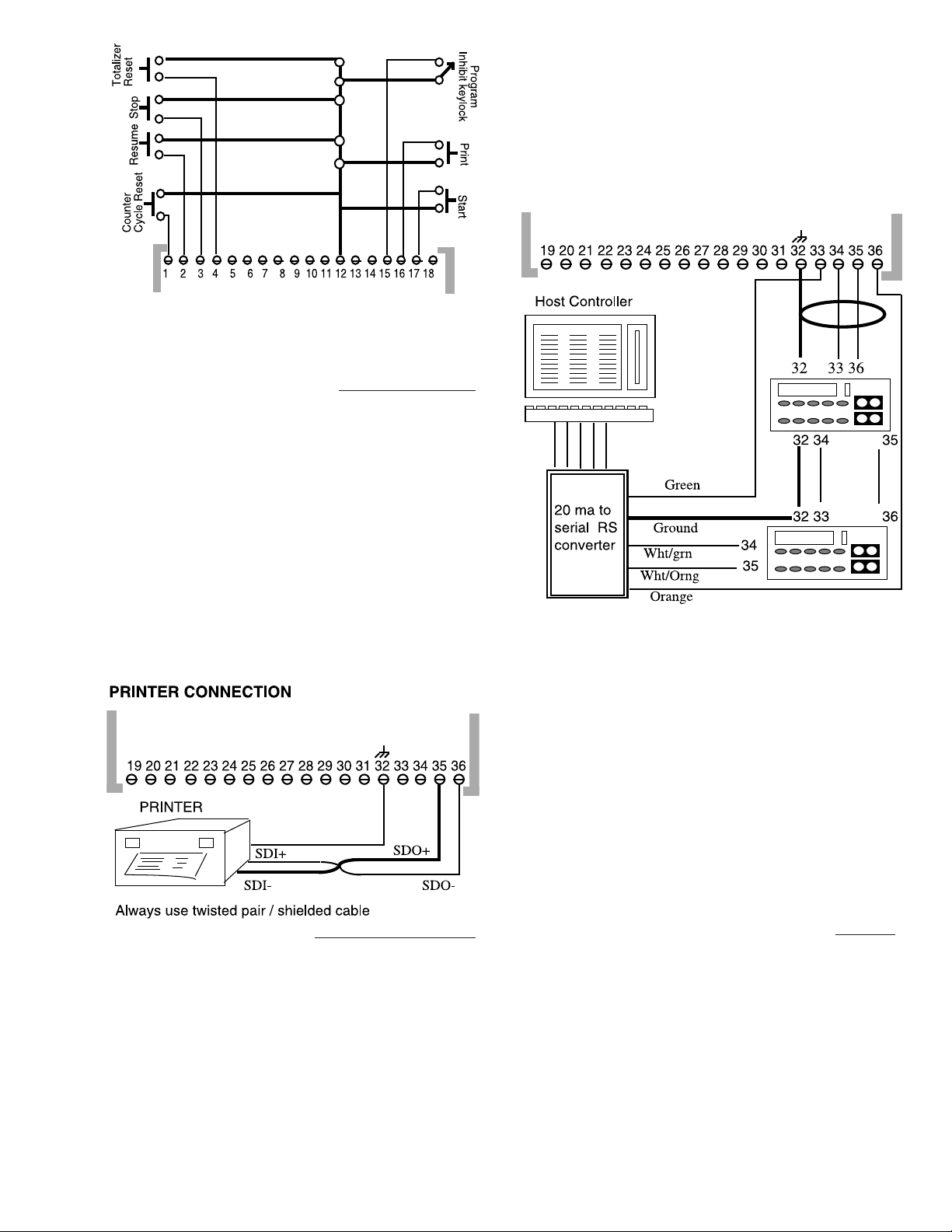
• START, STOP AND RESUME
These operations can be wired remotely for fast emergency override, or for cascading several units. If you inhibit
these functions with function #41, only STOP and RESUME
will still be operational with the remote control, START will
not. If a sustained ground (DC common) is applied to the
remote stop, all inputs are inhibited.
• The RESET CYCLE and RESET TOTALIZER are useful
for end of shift coordination and control. Both inventory totalizer and cycle counter can be reset to zero.
• The PRINT input allows you to request printed information at any point during the operation, in order to
inspect batch, flow, and inventory parameters.
8
Page 9
• The INHIBIT input allows you to connect a keylock or
jumper in order to disable function #41, which lets you
inhibit or uninhibit any or all functions.
• CONNECT A SERIAL PRINTER
The PC100 has terminals for serial input and output. The
type of signal is a 20 mA data loop. The serial output can be
used to transmit data to a serial printer. The input-output
is used to connect a process controller for two way serial
communication (transmit and receive.)
Commercial serial printers can be connected to the
PC100 to receive and print flow information at the end or
start of a batch or on command.
The connection to the PC100 requires that the printer be
able to receive a 20 mA serial data loop or that a current to
serial converter be used.
Always use twisted pair shielded cable for all serial
communications. Keep cable as short as possible and do not
place near power wires.
Function #66 may have to be programmed to the appro-
PC100 to the serial input of the next unit.
Serial connection will be interrupted to all units if the
power supply fails on any one of the PC100s. To prevent this
from happening, you may want to connect a communications
relay to each unit.
Wiring diagrams on how to connect the relay will be found
in the relay packaging.
Up to 99 PC100s can be connected in this manner. Each
unit sending and receiving information must be identified
with an ID number. (See page15.)
The information below shows the parameters that can be
reprogrammed by a host controller as “Information Received” and the parameters that the PC100 will transmit on
print or interrogation as “Information Sent”
priate line print delay for the printer in use.
• CONNECT A CONTROLLER
The two way serial communication ports allow you to
connect the PC100 to a process controller to send and
receive data.
The connection requires that the host controller be able
to accept a 20 mA data input. Otherwise, a 20 mA to RS signal
converter must be used.
To connect more than one PC100 in series, first connect
the 20 mA to RS transformer to the serial input of the
computer. Then, connect the serial output to the first PC100
as shown. Thereafter, connect the serial output of one
Information Received Information Sent
P = Fixed Prewarn Prewarn Setpoint
B = Batch Preset Batch Setpoint
C = Cycle Preset Cycle Setpoint
H = Rate High Setpoint Rate High Setpoint
L = Rate Low Setpoint Rate Low Setpoint
I = Print (Interrogate) Scale Factor
F = Scale Factor Totalizer Count
X = Stop Batch Count
R = Resume Cycle Count
S = Start Flow Rate
V = Parameters That Vary (Counters and Flow Rate)
• SERIAL COMMUNICATION CHARACTERISTICS
• Even parity transmission with no check for parity.
• On ID mode all characters are echoed and all lines
must start with ID #. (ID number of PC100 to be
interrogated.) Example: To change the batch from
150 to 180 on unit #3, you have to transmit #3B180*.
• When not on ID mode, characters are not echoed. All
lines to start with line initial. Example: To change
prewarn setpoint from 10 to 15, transmit P15*.
• If a line is accepted by the PC100, the * sign is changed
to @. However, if a wrong line is sent to the PC100, an
“INVALID REQUEST” message will be transmitted
along with the unit ID #. If a wrong value is sent, such
as prewarn larger than batch, a “VALUE ERROR”
9
Page 10

HOW TO OPERATE
THE PC100 PANEL
message will be transmitted.
The PC100 front panel consists of a display of six 7
segment LEDs, four yellow LED indicators, and a numeric/
command keypad. Some of the number keys have dual
function operation.
The panel provides watertight protection to the internal
components and can easily be replaced in case of damage.
A protective clear plastic cover is also available to protect the
label from dirt, paint, puncture, or scratches (order part
To View Counters or Control Operation: Using the front
panel you can view rate of flow, total and batch count, or
start, stop and resume operation by simply pressing the keys
so labeled.
To Program Functions: Press the function key, enter the
function number, press the ENTER key to view the present
value, change value, and press the ENTER key again to store
the new value in memory. (See next page on programming
sequence.)
number 58689-001.)
DUAL PURPOSE FUNCTION KEYS
In addition to serving as numerical keys to program batch
or other values, these keys can be used to program or display
batch values, totals, and rate of flow
The 1 key is used to program a new batch.
Press once, enter the batch value, and
press the ENTER key.
The 2 key is used to return the display to
batch count.
The 5 key is used to display the instantaneous flow rate in GPM, LPM, etc.
The 0 key is used to RESUME operation
from the point where a STOP command
was received.
START will reset the batch counter and
energize both outputs to begin batch operation.
Press STOP to de-energize both outputs
and to stop operation.
Press FUNCTION to start a program operation or to start over if a mistake is made.
Press 6 to read the
totalizer's four
upper digits.
Press 7 to read the
totalizer's six
10
Page 11

HOW TO PROGRAM
THE PC100
lower digits.
Programing the PC100 is very simple. Except for programming batch preset, all other functions are programmed the
same way.
This section gives:
• Details on how to operate the front panel to program,
step-by-step, each of the functions
• An explanation of the choices that are available for
each function
• Examples to guide you over the critical functions
BASIC PROGRAMMING SEQUENCE
Example: Change the fail safe time between pulses from
2 seconds to 5 seconds.
1 Press the FUNCTION key...............................
2 Press the function number 30.......................
3 Press ENTER (display will show present value)
the PC100 is used as a batch controller.
As we mentioned at the introduction of this manual, many
functions are available but only a few must be programmed
for the proper operation of the PC100. The functions in this
section are not presented in numeric order but instead in
order of priority first, and second, in groups of similar
operation, i.e., all batching functions, all rate functions, and
all communication functions.
Functions that must be programmed will be
marked with
tions are properly programmed.
a symbol. Be sure that these func-
4 Press the new value.......................................
5 Press ENTER................................................
FUNCTION PAGE
*1 Batch Preset 15
10 Fixed Prewarn 15
12 Batch Limit 15
13 Batch Autoadjust (Learning Mode) 15
15 Cycle Preset (How Many Batches to Run) 15
16 Viewing Cycle Counter 15
*18 Scale Factor 13
20 Rate Period Units Per Second, Minute or Hour 16
21 Rate Low Setpoint 16
22 Rate Hi Setpoint 16
30 Fail Safe (Shutoff if Pulse is Not Received) 12
31 Autorecycle (Time Between Equal Batches) 15
32 Prewarn Timeout (Prewarn Signal Duration) 15
33 Output 3 Select (Cycle, Totalizer or Alarm) 12
34 Rate Mode Enable 13
35 Serial Output Select (Pulse or Information) 17
36 Pulse Output Width (1 to 99 ms) 13
37 Rate Output Latch 16
41 Enable/Disable Functions 14
FUNCTION Page
42 Batch or Rate Display Default 13
43 Factory Default (All Functions) 14
44 Disable STOP 14
45 Disable RESUME 14
46 Disable START 14
*50 Count Mode (Up, Down, Quadrature) 12
*51 Reset or Preset 12
52 Totalizer Reset 16
53 Decimal Point Position 12
54 Cycle Counter Reset 16
60 Baud Rate Select 17
61 Print Data A Select 17
62 Print Data B Select 17
63 Print on START or STOP 17
64 Print on Command 17
65 Unit Identifier 17
66 Line Print Delay for Printers 17
67 On Line Message After Power Down 17
* These FUNCTIONS must be programmed when
11
Page 12

SETUP FUNCTIONS
The display will show...
Once all wiring has been completed, the unit can be
programmed for your application. Those functions marked
“MUST” have to be programmed if the PC100 is being used
as a batch controller.
FUNCTION #
This function allows you to program the way your transmitter input(s) will be counted in the display. Your choices
are as follows:
0 - Input on terminal #10 will count up,
1 - Input on either terminal will count up.
2 - Input on either terminal will count down.
3 - Inputs on both terminals will count up in
4 - Inputs on both terminals will count up in
Unless you are using quadrature transmitters, we recommend always using either code 1 to count up, or code 2 to
count down in order to be able to use either input.
50: COUNT DIRECTION
input on terminal #14 will count down.
quadrature.
double quadrature.
FUNCTION # 30: FAIL SAFE TIMEOUT
The pulse signal from the transmitter will be interrupted
if the transmitter, the meter, the pump or other component
fails. Enter 0 to turn off Fail Safe Timeout.
This function allows you to program a period of time from
1 to 99 seconds since the last pulse received. If a pulse is not
received in this period, the outputs are de-energized and the
operation is stopped. There is also a fixed fail safe for
starting operation. If no pulse is received in a 5 second period
following the start command, the operation is stopped.
Six zeros will flash to alert the operator of the failure. If
a printer is connected, the message “B count NO CNT” will
be printed.
To return the unit to normal operation after the problem
has been solved, you must press the STOP key first.
FUNCTION #
This function must be programmed if the scale factor was
set up for fractions of a gallon, liter, etc. To program, simply
enter the number of decimal points required on the display.
Example: If measuring in tenths of a gallon, then enter
1. If measuring in hundredths, then enter 2, and so on. The
display will show 0.1, 0.02 and 0.003 respectively. The programmed decimal point will also appear in the totalizer and
rate of flow indications.
53: DECIMAL POINT POSITION
FUNCTION # 51: RESET OR PRESET
After the count direction has been determined and
programmed, you have to decide what the counter should
show at the end of the batch. Your choices are as follows:
0 - If counting down, counter will stay at zero.
1 - If counting down, counter will go back to preset
value.
2 - If counting up, counter will stay at batch preset.
3 - If counting up, counter will go back to zero.
Example: You may decide to count from the preset down
to zero and at the end of the batch stay at zero so that you
know that the batch was run. On the other hand, you may
want the counter to reset to your batch value so that you may
know what the batch was set at before starting a new batch.
Programming this function is important because once
you press START the counter will immediately reset to zero
on count up, or to batch size on count down, and start the
operation. If you set the counter to stay at zero but would like
to know what your batch is before the next operation, just
press the 1 key and then the ENTER key.
FUNCTION # 33: TRANSISTOR OUTPUT MODE
Program this function only if you plan to use the transistor output on terminal #7 for one of these three available
options.
0 - Totalizer Output. This is a transistor scaled pulse
output. It is usually used to connect to remote totalizers or process controllers. The pulse width can be
programmed with function #36.
1 - End of Batch Output. This is a transistor output with
a variable pulse width that is activated at the end of
each batch. If connected to a remote counter, it can
be used to totalize the number of batches run for a
period of time (day, week, year or shift). If connected
to terminal #17, a second PC100, it can be used to start
12
Page 13

the second unit in order to cascade operations.
2 - Hi and/or Low Flow Rate Signal. If you program hi and
low rate setpoints, this transistor output is activated
when either setpoint is exceeded. The duration of this
pulse is determined by programming function #37.
Connect to a visual or audible alarm to alert you of
irregular flow conditions.
FUNCTION # 36: PULSE OUTPUT WIDTH
Program 1 to 99 ms. Certain electromechanical devices
require wider pulse widths. Factory default is 15 ms which
should be adequate for most applications. High frequency
output pulses require narrower pulse widths.
FUNCTION #
42: Default to BATCH or RATE DISPLAY
Normally, the PC100 is used to batch. Therefore, the
display will always automatically return to batch count after
a programming procedure (code 0). If the PC100 is used
mostly for rate of flow indication, program code 1 and the
display will return to flow rate instead of batch count.
FUNCTION # 34: RATE MODE ENABLE
When this function is activated (code 1), the PC100 can
only be used as a rate indicator and totalizer. All batch
functions will be inactive. The display will default to rate of
flow.
plier or SCALE FACTOR.
The table below shows the number of unscaled pulses for
each gallon of liquid flowing through the listed Badger flow
meters with selected transmitters.
If you want the PC100 to register in whole units, you must
divide 1 by the unscaled pulses. Program the decimal point
(function #53) for "0".
If you want the PC100 to register in 0.1 units, you must
divide 10 by the unscaled pulses. Program the decimal point
(function #53) for "1".
If you want the PC100 to register in 0.01 units, you must
divide 100 by the unscaled pulses. Program the decimal point
(function #53) for "2".
If you are scaling for any other unit of measure such as
pounds, liters, ounces, etc., multiply the scale factor (in
gallons) by the appropriate conversion factor.
Example: The unscaled pulses/gallon for a 2" OP meter
with a PFT2E transmitter is 20.56. If you wish to read to the
nearest 1/10 of a gallon, divide 10 by 20.56. The scale factor
to read to the nearest 1/10 of a gallon would be 0.4864.
Note: If you are using a gear type scaled transmitter, or
an electronic scaled transmitter, the PC100 scale factor
should be 1.0000. In this case, the scaling is done by the
transmitter.
Meter Transmitter Pulses Per Gallon
ˇ FT1
FT2XP
PFT2
PFT2E FT420XP PEPT1
Size Type PFT3E PFT420 PFT3 EPT1XP
1/2" OP 222.96 445.92 1170.54
1" OP 76.64 153.28 402.36
2" OP 20.56 41.12 107.94
2" Turbo 34.72 34.72 17.36
3" Turbo 24.80 24.80 12.40
4" Turbo 5.12 5.12 2.56
6" Turbo 2.16 2.16 1.08
5/8" 25 Ind RCDL 198.40 396.80 1041.60
3/4" 35 Ind RCDL 126.67 253.34 665.03
1" 40 Ind RCDL 89.80 179.60 471.75
1" 70 Ind RCDL 46.80 93.60 245.70
1 1/2" 120 Ind RCDL 23.80 47.60 124.95
2" 170 Ind RCDL 14.56 29.13 76.46
FUNCTION # 18: SCALE FACTOR CALCULATION
The transmitter sends out a finite number of pulses per
gallon, liter, etc. In order to display these pulses in engineering units of measure, they must be “scaled” (multiplied by a
constant.) Function #18 allows you to program this multi-
13
Page 14

ERROR CALIBRATION
To recalibrate the scale factor due to system error
caused by meter wear or fluid viscosity changes, follow this
procedure:
If necessary, modify the metering system so you can
collect the fluid after it flows through the meter during the
calibration procedure. You must be able to accurately weigh
or measure the fluid that passes through the meter. Be sure
there is sufficient back pressure to assure that the meter is
always filled with fluid.
Program a batch value into the PC100 that is larger than
the capacity of the vessel that will contain the fluid.
Push the START button on the PC100. Press the STOP
button when the fluid nears the capacity of the vessel you
are filling. Be careful not to overflow the vessel.
Accurately measure the fluid in the vessel. Observe the
PC100 display, and determine the quantity of fluid delivered
as determined by the PC100 reading.
Repeat the procedure two or more times to determine if
you have repeatability. You cannot recalibrate unless you
have repeatability. If you system is not repeatable, it is
probably due to mechanical problems with one or more
system components.
If your system is repeatable, use the following formula to
determine the new scale factor:
a 0 if disabled.
Press 0 to scroll up (functions 01.1, 10.1,12.1.....etc.)
Release the key to stop at the desired function. To disable or
enable that particular function, press ENTER. The first digit
will then change from 1 to 0 or from 0 to 1.
To scroll down (functions 12, 10, 1, 67, 66, etc.), press key
9. Press 2 to return to batch count or FUNCTION to continue
programming of other functions.
FUNCTION #
This function is used to disable the front panel STOP
command. Disabling the front panel STOP prevents accidental stopping of the process. The remote STOP can be connected for supervised emergency STOP operation.
Program function #44 at 1 to disable. While disabled the
STOP command can still be used to clear a FAIL SAFE
condition (see function #30).
44: DISABLE STOP
Quantity Delivered in VesselxOld Scale=New Scale
Quantity Indicated on PC100 Factor Factor
Use function #18 to enter the new scale factor into the
PC100.
FUNCTION # 41: ENABLE, DISABLE FUNCTIONS
This function allows you to enable or disable the operation of any one or combination of functions in order to
prevent accidental reprogramming or unwanted tampering
of the unit.
Note: Wiring a jumper or keylock switch across terminals
#15 and #12 will effectively restrict the use of this function.
You will be able to view the functions by scrolling up or down
but you will not be able to enable or disable them.
To operate this function, press: FUNCTION 41 ENTER. At
this point, you will see the three digits to the right. The two
digits to the left represent the function and the digit to the
right of the decimal point is a 1 if the function is enabled or
FUNCTION #
This function is used to disable the front panel RESUME
command. Disabling the RESUME command can prevent
accidental restarting of a bad batch without supervision.
This function can still be controlled remotely. Program the
code to 1 to disable.
FUNCTION # 46: DISABLE START
This function is used to disable the front panel START
command. Program the code to 1 to disable. Once disabled,
this function cannot be operated through the front panel
nor remotely. Disable START only when using the PC100 as
a nonresettable totalizer.
45: DISABLE RESUME
FUNCTION # 43: FACTORY DEFAULT
Programming this function to 1 will reprogram all functions to the values set at the factory:
#18 Scale Factor = 1.0000
#20 Flow Rate In = Units Per Minute (1)
#36 Totalizer Output = 15 ms (1)
#50 Count Mode = DOWN (2)
#51 Reset/Preset = Go to batch on down;
go to zero on up
14
#41 All Functions Enabled (1)
Page 15

PROGRAMMING TO BATCH
FUNCTION #
To program the batch, press 1, enter the batch value, and
press ENTER.
If you just want to see what your batch is set at, press 1.
Press ENTER to return to batch count.
1: PROGRAMMING BATCH AMOUNT
FUNCTION # 15: CYCLE PRESET
If you are running several batches of the same size using
the autorecycle feature, function #15 allows you to preset
the number of batches to be run automatically. When the
number of batches preset is reached, the unit will stop
recycling and wait for another START command. The cycle
counter is reset to zero at the end of the CYCLE preset.
FUNCTION #
0 - Batch Autoadjust Disabled. Totalizer input disabled at
1 - Batch Autoadjust Enabled. The PC100 will compensate
2 - Batch Autoadjust Disabled. Totalizer input always
FUNCTION # 12: BATCH LIMIT
This function is used to program a limit to the size of batch
that can be entered. This will prevent over batching.
Example: If the largest allowable batch in your operation is
255 gallons, then program the batch limit to 255 gallons.
Note: If the operator tries to enter a batch larger than
the limit, when he presses ENTER, the display will revert
back to the old value. Program to 0 if batch limit is not
needed.
13: BATCH AUTOADJUST
batch counter coincidence.
for any overrun at the end of the batch. Totalizer input
is always enabled.
enabled.
FUNCTION #
Use this function to view the number of batches run since
last reset. To reset the cycle counter to 0, use function #54
and program it to 1.
FUNCTION # 10: FIXED PREWARN PRESET
Program this function to control the first stage of a two
stage valve or for other prewarn functions (see page 7.) The
preset point will be fixed. That is, if you program a prewarn
of 5 gallons, the signal will be sent 5 gallons before the end
of the batch. CAUTION: The prewarn setpoint must be LESS
THAN THE BATCH SETPOINT or else six decimal points will
light up and prevent further operation. To clear, press STOP
and reprogram the prewarn setpoint.
16: CYCLE COUNTER VIEW
FUNCTION # 31: BATCH AUTORECYCLE
If your operation consists of several batches of the same
size, you can program the PC100 to start each batch automatically after a preset period of time (0.0 to 999.9 seconds).
This is useful in container filling operations.
FUNCTION # 32: PREWARN TIMEOUT
Normally, when the prewarn setpoint has been reached,
the relay K1 is de-energized until the batch is terminated.
However, if the prewarn signal is used to control an alarm
or a feed pump, the signal duration can be programmed from
1 to 99 seconds. Never use the time out if K1 is connected
to the first stage of a valve.
15
Page 16

PROGRAMMING FOR
FLOW RATE
RESETTING COUNTERS
FUNCTION # 20: FLOW RATE PERIOD
This function is programmed to view the rate of flow in
units per second, minutes or hours. Code 0 is for seconds,
1 is for minutes, and 2 is for hours. To view rate of flow, simply
press key number 5. To return to batch count, press key
number 2.
Note: Before programming the next two functions #21
and # 22, make sure that function #33 is set for rate output.
FUNCTION # 21: LOW FLOW SETPOINT
Use this function to preset a minimum flow rate. If the
rate falls below the setpoint, transistor on terminal #7 will
be energized. On startup, the PC100 will wait until the
minimum flow is reached before activating this function.
FUNCTION # 52: TOTALIZER RESET
Use function #52 to reset the totalizer to zero. The 10 digit
totalizer on the PC100 has a capacity to totalize up to
9,999,999,999 (ten billion.) The totalizer must be reset to
zero before this number is reached since the totalizer will
not roll over automatically.
FUNCTION # 54: CYCLE COUNTER RESET
Function #54 allows you to reset the cycle counter
(number of batches run) at any time. If function #15 is
programmed to a preset number, the cycle counter is reset
automatically when the preset number is reached. To reset,
press FUNCTION-54-ENTER-1-ENTER.
FUNCTION # 22: HI FLOW RATE SETPOINT
Use this function to preset a maximum flow rate. If the
rate exceeds the setpoint, transistor on terminal #7 will be
energized. Use the output to activate an alarm or other
indication devices.
Note: Make sure that the Low setpoint is lower than the
Hi setpoint. If not, the display will flash zeros, and if connected to a printer or computer, an ERROR message will be
transmitted.
FUNCTION # 37: RATE OUTPUT LATCH
The choices are two; Code 0 will cause the output to stop
if the rate returns to within the setpoints. With code 1, the
output will not stop until the end of the batch or until you
press STOP. The rate output can be connected to an alarm
to indicate overflow or underflow conditions.
16
Page 17

SERIAL COMMUNICATIONS
Program 3 to print both on START and on STOP.
FUNCTION # 35: SERIAL PULSE OR DATA
Program 0 to transmit and receive batch data or, program
1 to transmit only scaled pulses in serial form. When programmed to 1, all printer functions are disabled. Use code
1 only if the controller requires a pulse input instead of data.
FUNCTION # 60: BAUD RATE
This function must be programmed to match the communications speed rate of the printer or controller.
Program 0 for 1200 baud, 1 for 300 baud, 2 for 110 baud.
FUNCTION # 65: UNIT IDENTIFIER I.D.
When connecting more than one PC100 to a process
controller, program this function to assign an I.D. (1 to 99)
to each PC100. The I.D. can then be used to channel
communications from and to the host controller.
FUNCTION #
Program 1 to print at any time. This function can also be
operated remotely, at any time, with a switch connection
between terminals #12 and #16.
FUNCTION # 67: MESSAGE ENABLE
Programming this function to 1 will cause the PC100 to
send an “ON LINE” message to the controller or printer as
soon as the power is restored after a power failure.
FUNCTION #
Y select X select
0= K SCALE - FL RATE 0 = INV - C COUNT - B COUNT
1= K SCALE 1 = INV - C COUNT
2= FL RATE 2 = INV - B COUNT
3= nothing 3 = INV
64: PRINT COMMAND
61: PRINT DATA SELECT A
4 = C COUNT - B COUNT
5 = C COUNT
6 = B COUNT
7 = nothing
FUNCTION # 66: LINE PRINT DELAY
Printers often require different delay periods between
lines of information transmitted. This function must be
programmed to match the required line print delay of your
printer. Program 0 for 0.1 second and 1 for 1 second.
FUNCTION # 63: PRINT ON START AND/OR STOP
Program 1 to print on START.
Program 2 to print on STOP.
FUNCTION # 62: PRINT DATA SELECT B
Y select X select
0= RTE HI- RTE LO 0 = S CYCLE - S BATCH-PREWARN
1= RTE HI 1 = S CYCLE - S BATCH
2= RTE LO 2 = S CYCLE - PREWARN
3= nothing 3 = S CYCLE
4 = S BATCH - PREWARN
5 = S BATCH
6 = PREWARN
7 = nothing
K SCALE = SCALE FACTOR
FL RATE = FLOW RATE
INV = 10 DIGIT TOTALIZER
C COUNT = CYCLE COUNT
B COUNT = BATCH COUNTRTE
HI= HIGH FLOW SET
RTE LO= LOW FLOW PRESET
S CYCLE = PRESET CYCLE
S BATCH = PRESET BATCH
17
Page 18

TROUBLESHOOTING
THE PC100
PREWARN = PRESET PREWARN
This section deals with most of the common problems that
you may encounter with the PC100, the possible causes and
the recommended remedies. Most of the problems are due to
improper wiring and or programming procedures. However,
the problem may originate in the flow meter, valve, pump, or
PROBLEM POSSIBLE CAUSES REMEDIES
Unit is powered but the display 1. Incorrect AC or DC power wiring. 1. Recheck power wiring, fuses, etc.
does not light up.
Unit works fine but occasionally 1. Line noise is affecting processor 1. Use dedicated power or install
the display freezes up. due to a current spike or surge. surge suppression network.
Transmitter is connected but 1. Transmitter wiring is not correct. 1. Check wiring diagrams.
the PC100 does not count. 2. EPT1 transmitter current regulator. 2. Install current regulator module.
3. Transmitter is defective. 3. Replace parts or whole.
4. PC100 is defective. 4. To confirm, connect wire to terminal
5. Wrong scale factor. 5. Check scale factor calculation,
6. Low frequency jumper for slow 6. Disconnect low frequency jumper
pulse input is connected. from terminals #11 or #13.
other piece of equipment.
Make sure other equipment is functioning properly. All
PC100s are extensively tested at the factory before shipment. However, the units may get damaged during transit,
installation, or errors in wiring. If after all possible solutions
have been tried and the problem persists, contact your local
representative or call our Industrial Sales Department at
(414) 355-0400.
#12 and short to input terminals #10 or
#14. Each contact should produce a
visible count on the display when scale
factor = 1.
i.e., if programmed .0001 instead of
1.0000, unit will wait for 1000
pulses before decrementing count.
Relays do not de-energize at 1. Relays are not properly connected. 1. Reconnect relay wiring.
setpoints. 2. Relay is defective. 2. Replace relay.
3. Connection between transistor out- 3. Check connections.
puts #8 & #9 and relay inputs are loose.
4. Relays are not plugged in all the way. 4. Unplug and replug relays.
Counter accumulates 1. Switch bounce causing extra pulses. 1. Install low frequency jumper.
too many counts. 2. Electrical noise causing extra pulses. 2. Check wiring. Be sure power lines are
not bundled with signal lines. Use
shielded wire. Connect ground to
terminal 32.
3. Excessive vibration at meter. 3. Dampen vibration.
Some of the keys on the front 1. Defective switches. 1. Repair or replace PC100.
panel are not operational. 2. Unit is programmed to disable 2. Check programming functions.
certain switch functions.
Unit is operational but front 1. Operator using sharp objects to 1. Connect external remote switches
panel has excessive wear. program unit or certain keys are to control frequently used functions
used too often. and replace front panel.
Five decimal points light 1. Prewarn setpoint is larger than 1. Reprogram preset points.
up on the display. batch size.
Cannot program batch size, 1. Batch size exceeds batch limit. 1. Reprogram smaller batch or
display reverts back to deactivate batch limit.
old batch preset.
18
Page 19
PROBLEM POSSIBLE CAUSES REMEDIES
Cannot program preset points, 1. These cannot be preset unless the 1. STOP unit and program.
rate time base, or scale factor. unit is on a STOP condition. If you You cannot RESUME operation
STOP and reprogram, you must START
a new batch.
Cannot program HI or LOW 1. You have programmed Hi 1. Reprogram your setpoints.
flow setpoints. lower than Low.
The unit closes valves in the 1. Transmitter pulse has been inter- 1. Find reason of pulse interruption.
middle of a batch run and rupted and fail safe condition is active. STOP and reprogram fail safe period.
display flashes six zeroes. 2. Fail safe period is too short. 2. STOP and reprogram fail safe.
Pulse output connected to 1. Pulse width at 1 ms (too fast). 1. Reprogram pulse width.
remote counter but it does not 2. Reverse polarity. 2. Check wiring with diagram.
count.
Totalizer does not match 1. Totalizer does not stop counting 1. Check autoadjust function
sum of batches run. if autoadjust mode is active. and also check for leaky valves.
Flow alarm remains on until 1. Function #37 is programmed wrong. 1. Reprogram function #37.
end of batch instead of turning
off when flow rate returns to
normal.
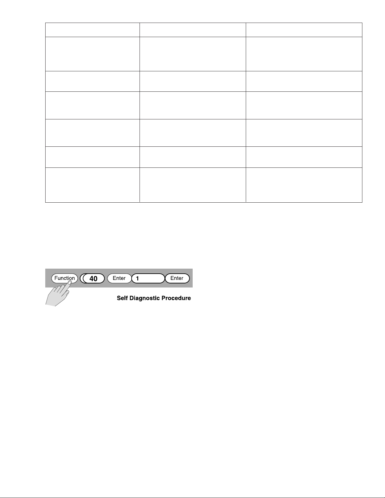
You have now checked all the above mentioned procedures and the unit is still not functioning appropriately.
There is the possibility that some internal component has
been damaged and it is preventing normal operation. At this
point, it is recommended that you run a diagnostic proce-
dure using function #40.
What this will do is put the PC100 into a self test of all
memories and timers.
During self test all digits and decimal points will light up
in ascending sequence. If a failure in the memory banks is
detected, then a 4 will flash. If the timers fail, an 8 will flash
and if there is a non-volatile memory failure, a 5 will flash.
Normally, the malfunction can be corrected by using function #43, Factory Default, to make sure that all values are
proper and then recycling power. Program each function
again and test the unit in operation. If the malfunction
persists, return the PC100 to the factory for evaluation.
Make sure to include a short description of the problem
so that we can test the unit for that specific condition.
CAUTION: There are no field replaceable parts inside.
Opening the unit will void all warranties.
Note: Before returning the unit to the factory call your local
representative or the factory to obtain a “Return Material
Approval”.
Carefully repack the PC100 in the original carton (or other
suitable container) and ship to:
ATTN: Customer Service Department
“PC100 FOR REPAIR”
Badger Meter Inc.
4545 W. Brown Deer Road
P.O. Box 245036
Milwaukee, WI 53224-9536
1-877-243-1010
19
Page 20

Please see our website at
www.badgermeter.com
for specific contacts.
Copyright © Badger Meter, Inc. 2009. All rights reserved.
Due to continuous research, product improvements and enhancements,
Badger Meter reserves the right to change product or system specifications
without notice, except to the extent an outstanding bid obligation exists.
BadgerMeter,Inc.
P.O. Box 245036, Milwaukee, WI 53224-9536
Telephone: (414) 355-0400 / (800) 243-1010
®
Fax: (414) 355-7499 / (866) 613-9305
www.badgermeter.com
 Loading...