

Page 1

Industrial Meters
Oscillating Piston, Model OP Chemical & Sanitary,
Sizes 1/2", 1", 2"
OPM-UM-00291-EN-02 (August 2013)
User Manual
Page 2

Industrial Meter, Oscillating Piston, Sizes 1/2" through 2" Model OP
Page ii August 2013
Page 3

User Manual
CONTENTS
SCOPE OF THIS MANUAL . . . . . . . . . . . . . . . . . . . . . . . . . . . . . . . . . . . . . . . . . . . . . . . . . . . . . . . . . . . . . . . . 5
Description . . . . . . . . . . . . . . . . . . . . . . . . . . . . . . . . . . . . . . . . . . . . . . . . . . . . . . . . . . . . . . . . . . . . . . 5
INSTALLATION . . . . . . . . . . . . . . . . . . . . . . . . . . . . . . . . . . . . . . . . . . . . . . . . . . . . . . . . . . . . . . . . . . . . . . . 6
Unpacking and Inspection. . . . . . . . . . . . . . . . . . . . . . . . . . . . . . . . . . . . . . . . . . . . . . . . . . . . . . . . . . . . . 6
Installation. . . . . . . . . . . . . . . . . . . . . . . . . . . . . . . . . . . . . . . . . . . . . . . . . . . . . . . . . . . . . . . . . . . . . . . 6
Dimension Examples . . . . . . . . . . . . . . . . . . . . . . . . . . . . . . . . . . . . . . . . . . . . . . . . . . . . . . . . . . . . . . . . 7
Performance Check . . . . . . . . . . . . . . . . . . . . . . . . . . . . . . . . . . . . . . . . . . . . . . . . . . . . . . . . . . . . . . . . . 8
OPERATING INSTRUCTIONS . . . . . . . . . . . . . . . . . . . . . . . . . . . . . . . . . . . . . . . . . . . . . . . . . . . . . . . . . . . . . . 9
General Operating Instructions. . . . . . . . . . . . . . . . . . . . . . . . . . . . . . . . . . . . . . . . . . . . . . . . . . . . . . . . . . 9
Shutdown Instructions . . . . . . . . . . . . . . . . . . . . . . . . . . . . . . . . . . . . . . . . . . . . . . . . . . . . . . . . . . . . . . . 9
MAINTENANCE. . . . . . . . . . . . . . . . . . . . . . . . . . . . . . . . . . . . . . . . . . . . . . . . . . . . . . . . . . . . . . . . . . . . . . 10
General . . . . . . . . . . . . . . . . . . . . . . . . . . . . . . . . . . . . . . . . . . . . . . . . . . . . . . . . . . . . . . . . . . . . . . . . 10
Preventive Maintenance . . . . . . . . . . . . . . . . . . . . . . . . . . . . . . . . . . . . . . . . . . . . . . . . . . . . . . . . . . . . . 10
Calibration Check and Adjustments . . . . . . . . . . . . . . . . . . . . . . . . . . . . . . . . . . . . . . . . . . . . . . . . . . . . . . 10
Servicing . . . . . . . . . . . . . . . . . . . . . . . . . . . . . . . . . . . . . . . . . . . . . . . . . . . . . . . . . . . . . . . . . . . . . . . 11
SPECIFICATIONS. . . . . . . . . . . . . . . . . . . . . . . . . . . . . . . . . . . . . . . . . . . . . . . . . . . . . . . . . . . . . . . . . . . . . 14
Page iii August 2013
Page 4

Industrial Meter, Oscillating Piston, Sizes 1/2" through 2" Model OP
Page iv August 2013
Page 5

User Manual
SCOPE OF THIS MANUAL
This manual contains information concerning the installation, operation and maintenance of Badger oscillating piston meters.
To ensure proper performance of the meters covered, the instructions given in this manual should be thoroughly understood.
Retain the manual in a readily accessible location for future reference.
Description
Badger oscillating piston meters are positive displacement type meters intended for use in fluid metering applications
involving chemical solutions or food ingredients. The meters are available in a variety of size and configurations that cover
a wide range of flow rates and special applications. The design of the meters incorporates a magnetic drive system that
minimizes the number of parts in contact with the fluid being metered. A removable housing cover provides easy access to
the internal components of a meter for cleaning and/or maintenance.
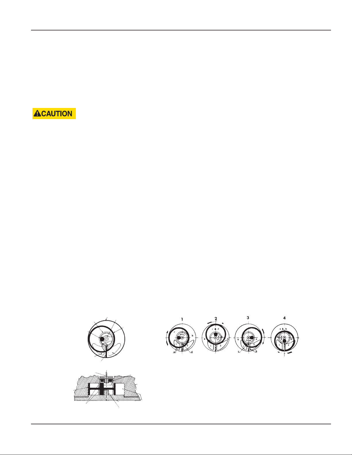
The basic components of an oscillating piston meter (see Figure 1) consists of a precision-machined housing, piston, magnet
assembly, control roller and housing cover. In operation, the piston functions as the measuring element. As fluid flows
through the meter, it causes the piston to oscillate within a measuring chamber in the meter housing. Each oscillation of the
piston is proportional to a specific volume of fluid. The specific volume measured varies with the size of the meter. The larger
the meter, the larger the volume of fluid measured for each oscillation of the piston. The circular oscillations of the piston are
magnetically coupled through the wall of the measuring chamber to a follower magnet or an electromagnetic pickup which
in turn operates a meter-mounted accessory such as a register or pulse transmitter.
HOUSING
PISTON
MAGNET ASSEMBLY
HOUSING COVER
RETAINING HARDWARE
"O" RING
HOUSING
COVER
CONTROL
ROLLER
Figure 1: Meter Components
Page 5 August 2013
Page 6

Industrial Meter, Oscillating Piston, Sizes 1/2" through 2" Model OP
INSTALLATION
Unpacking and Inspection
To avoid damage in transit, Badger oscillating piston meters are shipped to the customer in a special shipping container.
Upon receipt of the meter, perform the following unpacking and inspection procedures. If damage to the shipping container
is evident upon receipt of the meter, request the carrier to be present when the meter is unpacked.
1. Carefully open the shipping container following any instructions that may be marked on the container. Remove all
cushioning material surrounding the meter and carefully lift meter from container. Retain the container and all packing
material for possible use in reshipment or storage.
2. Visually inspect the meter for any physical damage such as scratches, loose or broken parts, or any other sign of
damage that may have occurred during shipment.
NOT:N If damage is found, request an inspection by the carrier's agent within 48 hours of delivery. Then file a claim with the
carrier. A claim for equipment damaged in transit is the responsibility of the customer.
Installation
The procedure covering the installation of a standard oscillating piston meter are essentially the same regardless of the meter
model being installed or the configuration involved. Before attempting the installation, read the instructions given in the
following paragraphs to become familiar with the requirements and procedures involved. Any special instructions required
for the installation and/or electrical connection of accessory equipment such as registers, pulse transmitters, remote batch
controllers, etc., will be provided as a supplement to the manual.
Preliminary Considerations
Factors to consider before proceeding with installation:
1. Avoid locating the meter in close quarters. The area in which the meter is to be installed should provide adequate
space to permit cleaning and maintenance.
2. Verify that the operating temperature range of the meter is compatible with the temperature range of the uid or
uids to be metered.
THE METER MUST BE OPERATED WITHIN ITS RATED TEMPERATURE RANGE TO OBTAIN OPTIMUM ACCURACY AND
PREVENT DAMAGE TO THE METER PISTON.
3. Ensure that the ow range of the meter agrees with the ow rate or rates to be used in metering the uid.
THE LIFE OF THE METER MAY BE SERIOUSLY IMPAIRED IF OPERATED AT FLOW RATES ABOVE THOSE SPECIFIED.
4. If solid material is present in the uid to be metered, it may be necessary to install a strainer in the facility piping ahead
of the meter. In metering applications involving slurries, the nely divided, undissolved solids must be maintained
as a suspension in the liquid. Oscillating piston meters are positive displacement type meters and may not operate
properly with liquids containing solid particles unless the above precautions are observed.
5. In metering applications involving abrasive materials, slurries, or liquids that may leave a residue or buildup
of deposits, a meter by-pass and ushing system should be incorporated into the facility piping installation to
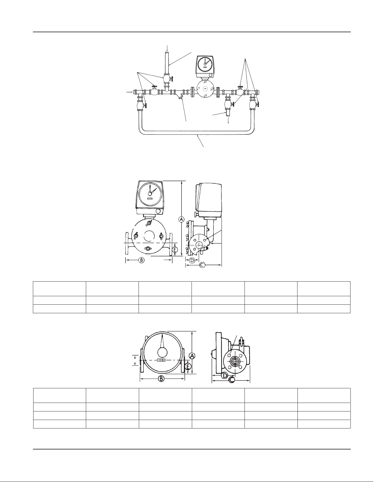
permit periodic clean-out of the meter. Figure 2 illustrates a typical meter installation incorporating a bypass and
ushing system.
Page 6 August 2013
Page 7
User Manual
Dimension Examples
CUTOFF
VALVES
FLUSHING SYSTEM INLET
FLUSHING SYSTEM
OUTLET
STRAINER
BY-PASS SYSTEM
Figure 2: Installation Configuration
CUTOFF VALVES
4 5/8 Dia. Holes
Equally Spaced on 3
1/8 Dia. B.C.
150# F.F.
1" Flange
with F.F.
Flanges
Figure 3: Dimensions example 1
Meter Size
A
Height
B
Laying Length
C
Depth
D E
1" 18-15/16" 11" 8-1/8" 3-7/8" 2-7/8"
2" 19-13/32" 12-5/8" 10-1/16" 5-5/8" 3"
4 5/8 Dia. Holes
Equally Spaced on 2
3/8 Dia. B.C.
1 3/8 Dia.
Meter Size
A
Height
B
Laying Length
C
Depth
D E
1/2" 6-3/8" 6-3/4" 6-3/8" 4" 2-3/8"
1" 7-5/8" 11" 8" 3-5/8" 2-7/8"
2" 8-1/2" 12-5/8" 10-7/8" 5-1/2" 3"
Figure 4: Dimension example 2
Page 7 August 2013
Page 8

Industrial Meter, Oscillating Piston, Sizes 1/2" through 2" Model OP
Installing the Meter
The oscillating piston meters are designed for in-line installation. Examples of dimensions of the meter models,
including laying lengths, are shown in "Figure 3". After reviewing the applicable dimension requirements, perform the
following procedures:
1. Install appropriate mating connectors in pipeline. Provide proper gap length for meter. On meters with anged ends,
allow for gaskets at both inlet and outlet of meter.
NOT:N Always install meter in such a way that round cover is on a vertical plane, as shown on "Figure 2".
2. Install meter in pipeline making sure that ow arrow on housing cover is in proper relation to the direction of ow of
the liquid.
3. Depending on meter size and line size, consideration may be given to placing a support under the meter to relieve any
strain on the facility piping caused by meter weight.
Performance Check
Check the following to ensure the meter is properly installed and operational.
1. Check all piping connections to the meter for proper mating and rm connection.
2. Apply uid pressure to the meter and check connections for possible leaks. Retighten connections as required.
3. Perform a functional test of the meter using the calibration check and adjustment procedures given in
“Calibration Check and Adjustments” on page 10.
Page 8 August 2013
Page 9
User Manual
OPERATING INSTRUCTIONS
General Operating Instructions
The instructions for operating an oscillating piston meter depend on the meter-accessory combination and the type of flow
control devices used in the facility piping. In general, the operation is either manually controlled or accessory controlled.
Manual operation applies to metering applications employing hand-operated valves or other manually-activated, flowregulating devices that are not functionally controlled by a meter-accessory device. Accessory controlled operation is used in
metering applications involving meter-accessories that provide a signal output to activate and/or deactivate a valve or other
type of flow control device.
REGARDLESS OF THE OPERATING PROCEDURE USED, THE VALVES OR DEVICES CONTROLLING THE FLUID FLOW
THROUGH THE METER MUST ALWAYS BE OPENED AND CLOSED SLOWLY TO PREVENT SHOCK LOADS THAT MAY
DAMAGE THE PISTON.
Manual Operation
Instructions are limited to the following start and stop procedures. The procedures are intended for use in simple metering
applications where the flow of fluid through the meter is controlled by hand-operated valves located in the facility piping
upstream and downstream of the meter.
1. Slowly open the upstream valve to apply uid to the meter.
2. Slowly open the downstream valve to initiate metering.
3. Adjust the downstream valve so the ow rate does not exceed the ow rate specication of the meter.
NOT:N On meters equipped with an accessory device providing a totalizing indicator, the flow rate can be checked by timing
the number of gallons registered in one minute.
4. To stop metering, slowly close the downstream valve; then close the upstream valve.
Accessory Controlled Operation
The step-by-step operating procedures used in accessory controlled metering applications are dependent on the specific
function of the accessory employed and its electrical interconnection with a flow control device or devices. See the
accessory's User Manual for specific operating instructions.
Shutdown Instructions
If a meter is to be shut down for an extended period of time (particularly when the application involves the metering
of slurries or abrasive solutions), its measuring chamber should be thoroughly flushed out to prevent the settling
out of undissolved solids or the accumulation of corrosive deposits. See “Preventive Maintenance” on page 10 for
cleaning instructions.
CYLINDRICAL
ABUTMENT
PISTON HUB
INLET PORT
PARTITION PLATE
FOLLOWER MAGNET
PISTON
CYLINDRICAL ABUTMENT
MEASURING CHAMBER
CONTROL ROLLER
CONTROL ROLLER
PISTON
OUTLET PORT
MAGNET ASSEMBLY
COVER
Diagram 1
Spaces "a" and "c" are receiving liquid from the inlet port "1"
and spaces "b" and "d" are discharging liquid through the
outlet port "2".
Diagram 2
The piston has advanced and space "a" in connection with the
HOUSING
MEASURING
CHAMBER
inlet port "1", has enlarged; and space "b" in connec tion with
the outlet port "2", has decreased. Spaces "c" and "d", which
have combined, are about to move into position to discharge
through the outlet port "2".
Figure 5: Shutdown Instructions
Diagram 3
Space "a" is still receiving liquid from the inlet port "1" and space
"c" is just opening again to the inlet port. Spaces "b" and "d" are
discharging through the outlet port "2".
Diagram 4
Liquid is being received by space "c" from the inlet port "1"
while liquid is being discharged from spaces "d" through the
outlet port "2". Spaces "a" and "b" have combined and are
about to discharge through the outlet port "2", as the piston
moves around to occupy the position as shown in Diagram 1
to begin the cycle again.
Page 9 August 2013
Page 10

Industrial Meter, Oscillating Piston, Sizes 1/2" through 2" Model OP
MAINTENANCE
General
This section contains information for servicing and maintaining of the meter. The information consists of preventive
maintenance, calibration and adjustment and general servicing procedures. Instructions for ordering replaceable parts
and assemblies are provided in an Illustrated Repair Parts Bulletin that is included with this manual. Any service and repair
procedures applicable to a meter-mounted or free-standing accessory are provided in the bulletin or instruction manual
covering the device.
Preventive Maintenance
The purpose of preventive maintenance is to ensure efficient operation and long life by detecting and correcting any defects
before damage or meter failure occurs. Preventive maintenance consists of periodic inspection and cleaning procedures.
The procedures should be performed at regular intervals and any defects discovered should be corrected before attempting
further operation.
1. Visually inspect the meter and applicable accessory for loose connections, missing hardware, cracked or broken dial
glass, damaged wiring or any other signs of wear or deterioration. Repair or replace parts as necessary.
2. Clean all dust, dirt or other foreign material from the exterior of the meter and accessory.
3. Fluid metering applications involving food ingredients require that Only manual cleaning (remove meter housing
cover) can be used for sanitary OP meters.
4. Fluid metering applications involving chemical solutions can be cleaned manually or mechanically by a meter bypass
and ush system.
If the facility piping arrangement includes a meter bypass and flushing system (see "Figure 2"), shut off fluid flow to the meter
and flush interior of meter housing with clean water to remove any buildup of deposits or corrosion. If a bypass and flushing
system is not included in the metering application, remove the meter housing cover and inspect the measuring chamber,
piston and associated parts for any buildup of deposits or corrosion. Clean and flush parts with water or a suitable solvent that
will not adversely affect the plastic components.
Calibration Check and Adjustments
All meters are accuracy tested with water at the factory using calibrated test equipment. However, because the meter can
be used to measure a wide variety of liquids that may vary from water in viscosity, it is sometimes necessary to recalibrate a
meter under actual operating conditions with the liquid being metered.
The following instructions are provided to assist in performing an on-site calibration check and adjustment.
Accuracy Test
1. Place a test tank of calibrated volume at the output of the meter.
2. Operate meter until test tank is lled to the appropriate calibrated level. Since meter accuracy varies somewhat with
ow rate, make test run at the same ow rate used in actual operation.
3. Record quantity indicated on applicable meter accessory device.
4. Repeat run three times and average recorded indications.
5. Perform the following calculation to determine the percent of accuracy of the meter.
Example 1: In this example, the meter accessory is slow and must be speeded
up by a calibration correction.
Example 2: In this example, the meter accessory is fast and must be slowed
down by a calibration correction.
Page 10 August 2013
Page 11

User Manual
Change Gear Corrections
If the accuracy test of a meter-accessory combination that incorporates change gears indicates that adjustment is required,
perform the following procedures.
1. See the Parts List for the location of the calibrating change gears.
2. Determine the number of teeth and the outside diameter of the existing change gears.
NOT:N The number of teeth and the outside diameter are stamped on each gear.
3. Submit an order for corrective change gears to the nearest Badger Meter Representative or the Industrial Division of
Badger Meter, Inc. Provide the following information when ordering:
• Meter Model, Size and Serial Number
• Accessory Device
• Unit of Measure or Pulse Rate/Unit of Measure
• Number of Teeth and Diameter of Existing
• Change Gears (Identify meter gear and register gear)
• Percent of Accuracy of Meter
Change Gear Replacement
No special procedures are required when replacing change gears. However, take care to obtain full mesh of the gears. When
installing a BRE, BRP or TR Register to a right-angle drive gear train, you can achieve proper gear mesh by observing or
marking the position of the change gears on the respective spindles at the time of removal and making the replacement in
the same position.
TAKE CARE NOT TO BEND THE SPINDLES WHEN INSTALLING THE GEARS OR REASSEMBLING A GEAR DRIVEN
ACCESSORY TO THE METER.
Electronic Scaling Correction/Recalibration
If the test results indicate an adjustment is required where a meter-accessory combination incorporates an electronic
calibrating feature, see the instruction manual for that accessory for the procedure to change scale factor.
Servicing
When periodic inspection or faulty operation of a meter indicates a need for servicing, refer to the following paragraphs for
instructions covering the removal, inspection and reassembly of the replaceable parts comprising a meter. Use the exploded
views given in the meter's Parts List as an aid in locating, identifying and removing parts and assemblies. If satisfactory repair
cannot be made, contact the nearest Badger Meter Representative or the Industrial Division of Badger Meter, Inc.
Measuring Chamber
Instructions for removing, inspecting, and reassembling the parts contained within the measuring chamber are essentially the
same, regardless of the size or type of meter involved.
1. Removal
a. Shut off the fluid flow to the meter.
b. Place a bucket or pan under the meter and relieve the fluid pressure in the meter by uniformly loosening the wing
nuts on the cover (on 1/2" meters loosen the hinged, ring-clamp.) Fluid will spill out around the cover as pressure
is relieved.
c. Remove the wing nuts and housing bolts (ring-clamp on 1/2" meters) and carefully remove the meter cover.
d. Remove the control roller from the pin in the center of the housing cover and the piston and magnet assembly
from the measuring chamber.
Page 11 August 2013
Page 12

Industrial Meter, Oscillating Piston, Sizes 1/2" through 2" Model OP
2. Inspection
a. Carefully examine the piston for warpage, cracks or other signs of wear and deterioration. Replace piston,
if necessary.
b. Check the magnet assembly and magnet assembly bushing (located on center pin inside chamber) for excessive
wear and corrosion. Replace, if necessary.
c. Check the control roller and control roller bushing. Replace, if necessary.
d. Inspect the housing cover O-ring for wear and deterioration. Replace, if necessary.
3. Reassembly
a. Place the magnet assembly on the bushing on the center pin inside the measuring chamber. Make sure the magnet
assembly rotates freely.
NOT:N Magnet bushing must be snug on the housing pin. Replace the bushing, if necessary.
b. Align the teardrop slot in the piston with the partition plate of the measuring chamber. Insert the piston into the
chamber. Make sure the piston moves freely.
c. Install the control roller over the bushing on the center pin in the housing cover. The control roller is easily
positioned over the center pin when meter is in vertical position. Make sure control roller rotates freely.
d. Align the holes in the cover with the mounting holes in the housing. Secure the cover in place with housing bolts
and wing nuts (on 1/2" meter the cover is secured with a hinged, ring-clamp).
Drive Systems
Instructions for removing, inspecting and reassembling the accessory drive systems follow.
Magnetic Drive Adapter Assembly
1. Removal
a. To remove the accessory from the castellated fitting on the adapter assembly, loosen the accessory seal screw and
rotate the accessory 1/4 turn.
b. Remove the three screws and washers securing the adapter assembly to the rear of the meter housing and carefully
lift the adapter from the meter.
3. Inspection
a. Check that the drive assembly operates freely when the follower magnet and spindle assembly at the front of the
adapter is rotated.
b. Check magnets, thrust bearing, ball races, and race retainer for signs of wear or corrosion. Clean and/or replace
parts as necessary. If necessary, apply light coat of Lubriplate #905, Gredag #53A, or equivalent to thrust bearing.
3. Reassembly
a. Secure the adapter assembly to the rear of the meter housing with the screws and washers removed in step 16.
b. Install the accessory onto the adapter assembly and secure it in place with the seal screw.
Page 12 August 2013
Page 13

Angle Drive Gear Train (1" and 2" Meters Only)
1. Removal
a. Remove the accessory device from the right-angle drive gear train.
b. Remove the three acorn nuts securing angle drive gear train to the rear of meter housing and carefully pull the gear
train the from locating studs.
3. Inspection
a. Check that the gear train operates freely when the follower magnet is rotated.
b. Check the magnet-spindle assembly, thrust bearing, worm gear, drive spindle and bushings for wear and corrosion.
Clean and/or replace parts as required. If necessary, apply a light coat of Lubriplate, Gredag #53A, or equivalent to
the bearing and gears.
3. Reassembly
a. Align the mounting holes in the angle drive gear train with the locating studs at the rear of the meter housing and
slide the gear train into place. Secure with acorn nuts.
b. Install the accessory on the angle drive the gear train. Make sure that the change gear on the output spindle of the
gear train meshes properly with the change gear on the input spindle of the accessory.
Straight Drive Gear Train (1" and 2" Meters Only for MS-1 Transmitter)
1. Removal
a. Remove the three acorn nuts securing the gear train hood to the rear of the meter and remove the hood.
b. Loosen the two screws and clamps securing MS-1 pulse transmitter to the gear train and remove the transmitter.
c. Remove the straight drive gear train from the rear of the meter housing by removing the three #6-32 screws.
4. Inspection
a. Check that the gear train operates freely when thr follower magnet is rotated.
b. Check the magnet-spindle assembly, gears and bushing and plate assembly for signs of wear and/or corrosion.
Clean or replace parts as required. If necessary, lubricate the gears with light coat of Lubriplate, Gredag #53A,
or equivalent.
3. Reassembly
a. Secure the gear train assembly in place at the rear of meter housing with 6-32 screws retained from removal.
b. Install the MS-1 pulse transmitter and secure to the gear train assembly by the tightening clamp screw. Make sure
that the change gear on the output spindle of the gear train meshes properly with the change gear on the input
spindle of the transmitter.
c. Align the mounting holes in the gear train hood with the locating studs extending from the rear of the meter
housing and slide the hood into place over the transmitter and gear train. Secure the hood in place with acorn nuts.
User Manual
Recalibration
After repair or replacement of a meter part or assembly, perform a calibration check to ensure that the meter operates
properly. See “Calibration Check and Adjustments” on page 10.
Page 13 August 2013
Page 14

Industrial Meter, Oscillating Piston, Sizes 1/2" through 2" Model OP
SPECIFICATIONS
1/2" 1" 2"
Minimum Flow Rate, Q Minimum 1.5 gpm 5.5 gpm 25 gpm
Continuous Operating Maximum Rate 4 gpm 20 gpm 65 gpm
Short Duration Maximum Flow, Q Maximum
Continuous operation is acceptable at these rates, but accelerated wear of the
piston and/or bushings may occur.
Standard Flange Connections*, Chemical 150* psi ANSI 16.5 150 psi ANSI 16.5 150 psi ANSI 16.5
1/2" Chemical meter can be ordered with 1" anges for low ow applications on 1" lines. All
sizes available with optional 300 psi anges.
Standard Connections, Sanitary
Sanitary OP meters have 3A approval, Ultem piston required.
Pressure Drop at
Maximum Continuous Operating Flow
(@ viscosity & specic gravity of water)
Maximum Viscosity Limit 10,000 cps (flow range is decreased as viscosity increases).
Maximum Operating Pressure 150 psi (300 psi optional)
Maximum Operating Temperature 250 °F
Minimum Operating Temperature**
**Minimum temperature for stated accuracy.
Accuracy ± 0.5% over entire meter flow range
Repeatability ± 0.2% or better under similar repeatable batch operations
6 gpm 30 gpm 100 gpm
Tri-Clamp Tri-Clamp Tri-Clamp
1.8 psi 6.3 psi 10.6 psi
Pressure loss increases with fluid viscosity
Contact factory for higher viscosities
40 °F
Page 14 August 2013
Page 15

INTENTIONAL BLANK PAGE
User Manual
Page 15 August 2013
Page 16

Trademarks appearing in this document are the property of their respective entities. Due to contin uous re search, product improv ements and enhance ments, Badger Meter
rese rves th e right to change product or system specications without notice, except to the extent an outstanding contractual obligation exists.
© 2013 Badger Meter, Inc. All rights reserved.
www.badgermeter.com
The Americas | Badger Meter | 4545 West Brown Deer Rd | PO Box 245036 | Milwaukee, WI 53224-9536 | 800-876-3837 | 414-355-0400
México | Badger Meter de las Americas, S.A. de C.V. | Pedro Luis Ogazón N°32 | Esq. Angelina N°24 | Colonia Guadalupe Inn | CP 01050 | México, DF | México | +52-55-5662-0882
Europe, Middle East and Africa | Badger Meter Europa GmbH | Nurtinger Str 76 | 72639 Neuen | Germany | +49-7025-9208-0
Czech Republic | Badger Meter Czech Republic s.r.o. | Maříkova 2082/26 | 621 00 Brno, Czech Republic | +420-5-41420411
Slovakia | Badger Meter Slovakia s.r.o. | Racianska 109/B | 831 02 Bratislava, Slovakia | +421-2-44 63 83 01
Asia Pacic | Badger Meter | 80 Marine Parade Rd | 21-04 Parkway Parade | Singapore 449269 | +65-63464836
China | Badger Meter | 7-1202 | 99 Hangzhong Road | Minhang District | Shanghai | China 201101 | +86-21-5763 5412 Legacy Document Number: IOM-020-12
 Loading...