

Page 1
Combustion Analyzer
for Commercial & Light Industrial Use
®
Combustion & Emissions
P/N: 0024-9551 | February 2019 Revision 2
User
Manual
Page 2

PCA® 400 User Manual
WARRANTY POLICY
Bacharach, Inc. warrants to buyer that at the time of delivery this product will be free from defects in material and
manufacture and will conform substantially to Bacharach, Inc.’s applicable specications. Bacharach’s liability and
buyer’s remedy under this warranty are limited to the repair or replacement, at Bacharach’s option, of this product or
parts thereof returned to seller at the factory of manufacture and shown to Bacharach, Inc.’s reasonable satisfaction to
have been defective; provided that written IMPORTANT of the defect shall have been given by buyer to Bacharach, Inc.
within one (1) year after the date of delivery of this product by Bacharach, Inc.
Bacharach, Inc. warrants to buyer that it will convey good title to this product. Bacharach’s liability and buyer’s remedy
under this warranty of title are limited to the removal of any title defects or, at the election of Bacharach, to the
replacement of this product or parts thereof that are defective in title.
THE FOREGOING WARRANTIES ARE EXCLUSIVE AND ARE GIVEN AND ACCEPTED IN LIEU OF (I) ANY AND ALL
OTHER WARRANTIES, EXPRESS OR IMPLIED, INCLUDING WITHOUT LIMITATION THE IMPLIED WARRANTIES OF
MERCHANTABILITY AND FITNESS FOR A PARTICULAR PURPOSE: AND (II) ANY OBLIGATION, LIABILITY, RIGHT,
CLAIM OR REMEDY IN CONTRACT OR TORT, WHETHER OR NOT ARISING FROM BACHARACH’S NEGLIGENCE,
ACTUAL OR IMPLIED. The remedies of the buyer shall be limited to those provided herein to the exclusion of any
and all other remedies including, without limitation incidental or consequential damages. No agreement varying or
extending the foregoing warranties, remedies or this limitation will be binding upon Bacharach, Inc. unless in writing,
signed by a duly authorized ocer of Bacharach.
Register Your Warranty by Visiting: www.mybacharach.com
SERVICE POLICY
Bacharach, Inc. maintains a service facility at the factory. Some Bacharach distributors / agents may also have repair
facilities; however, Bacharach assumes no liability for service performed by anyone other than Bacharach personnel.
Repairs are warranted for 90 days after date of shipment (sensors, pumps, lters and batteries have individual warranties).
Should your analyzer require non-warranty repair, you may contact the distributor from whom it was purchased or
you may contact Bacharach directly.
If Bacharach is to do the repair work, send the monitor, prepaid, to the closest service center.
Prior to shipping equipment to Bacharach, visit www.mybacharach.com for an Returned Merchandise Authorization
Number (RMA #). All returned goods must be accompanied with an RMA #. Pack the equipment securely (in its original
packing, if possible), as Bacharach cannot be held responsible for any damage incurred during shipping to our facility.
Always include your RMA #, shipping address, telephone number, contact name, billing information and a description
of the defect as you perceive it. You will be contacted with a cost estimate for expected repairs prior to the performance
of any service work. For liability reasons, Bacharach has a policy of performing all needed repairs to restore the
monitor to full operating condition.
IMPORTANT
Product improvements and enhancements are on-going, therefore the specications and information contained in
this document may change without IMPORTANT.
Bacharach, Inc. shall not be liable for errors contained herein or for incidental or consequential damages in connection
with the furnishing, performance, or use of this material.
No part of this document may be photocopied, reproduced, or translated to another language without the prior
written consent of Bacharach, Inc.
Copyright © 2019, Bacharach, Inc., All Rights Reserved.
BACHARACH, PCA, B-SMART, and FYRITE are registered trademarks of Bacharach, Inc. All other trademarks, trade names, service marks and logos
2
referenced herein belong to their respective companies.
0024-9551 Revision 2
Page 3

PCA® 400 User Manual
Table of Contents
Introduction ..................................................... 6
1.1 About this Manual ........................................................................................................... 6
1.2 Conventions ...................................................................................................................... 6
1.2.1 Short Form Instructions...............................................................................................................................6
1.2.2 Iconography .................................................................................................................................................. 7
1.3 General Safety Statements ............................................................................................. 7
1.4 Product Overview ............................................................................................................ 8
1.5 North America (NA) vs. Siegert (S) Combustion Equations .......................................... 9
Product Description ....................................... 10
2.1 Combustion & Emissions Analyzer .............................................................................. 11
2.1.1 Overview ......................................................................................................................................................11
2.1.2 Keypad .........................................................................................................................................................12
2.1.3 Display .........................................................................................................................................................12
2.1.4 Instrument Connections ............................................................................................................................14
2.1.5 Interfaces ....................................................................................................................................................15
2.1.6 Components ...............................................................................................................................................16
2.2 Sample Line & Probe Assembly .................................................................................... 17
2.3 PowerCongurations .................................................................................................... 18
Operation ........................................................ 19
3.1 Setup................................................................................................................................ 19
3.1.1 Operation Tips ............................................................................................................................................19
3.1.2 Inspection / Prerequisites ..........................................................................................................................21
3.1.3 Connecting Probe Assembly ......................................................................................................................22
3.2 Performing Combustion Test ....................................................................................... 23
3.2.1 Combustion User Preferences ..................................................................................................................23
3.2.2 Combustion Analysis .................................................................................................................................24
3.2.3 Additional Settings .....................................................................................................................................27
3.2.4 Combustion Average Test ..........................................................................................................................31
3.3 Performing Pressure Test ............................................................................................. 32
3.3.1 Pressure User Preferences ........................................................................................................................32
3.3.2 Pressure Analysis ........................................................................................................................................32
3.4 Performing Leak Tests (Siegert Only) ............................................................................ 34
3.4.1 Let-by Test ...................................................................................................................................................34
3.4.2 Tightness Test .............................................................................................................................................35
3.5 Performing Temperature Test ..................................................................................... 36
3.5.1 Temperature User Preferences .................................................................................................................36
3.5.2 Temperature Analysis ................................................................................................................................37
3
0024-9551 Revision 2
Page 4

PCA® 400 User Manual
Settings & Features ........................................ 39
4.1 Language Selection ........................................................................................................ 39
4.2 Date & Time .................................................................................................................... 39
4.3 Username ....................................................................................................................... 40
4.4 Button Sound ................................................................................................................. 41
4.5 Inactivity Timeout .......................................................................................................... 41
4.6 Post-Purge Period .......................................................................................................... 41
4.7 Carbon Monoxide (CO) Zero ......................................................................................... 41
4.8 Sensor Setup ................................................................................................................... 42
4.9 Bluetooth® Setup ........................................................................................................... 43
4.10 Printer Setup ..................................................................................................................44
4.11 Onboard Data Logging ..................................................................................................45
4.12 Memory File Management ............................................................................................46
4.13 Fresh Air Purge without Removing Probe ..................................................................47
4.14 Sensor Protection / Dilution Mode ..............................................................................48
4.15 Smoke Number Test ...................................................................................................... 49
4.16 Oil Derivative Test ..........................................................................................................50
4.17 Boiler Temperature Test ............................................................................................... 50
4.18 Combustion Equations .................................................................................................. 50
Care & Maintenance ...................................... 51
5.1 Emptying the Water Trap .............................................................................................. 51
5.2 Replacing the Filter Element ........................................................................................ 52
5.3 Cleaning the Probe Assembly ....................................................................................... 53
5.4 Sensor Replacement ...................................................................................................... 54
5.5 B-Smart® Sensor Calibration ........................................................................................ 57
5.5.1 B-Smart® Sensors .......................................................................................................................................57
5.5.2 Starting a Calibration ................................................................................................................................58
5.5.3 B-Smart® Sensor Calibration ....................................................................................................................58
4
0024-9551 Revision 2
Page 5

PCA® 400 User Manual
5.6 Manual Sensor Calibration ........................................................................................... 61
5.6.1 Starting a Calibration ................................................................................................................................61
5.6.2 CO
5.6.3 SO2 Sensor Calibration ..............................................................................................................................65
5.6.4 NO Sensor Calibration ...............................................................................................................................66
5.6.5 NO2 Sensor Calibration .............................................................................................................................67
5.6.6 CO
Sensor Calibration ..........................................................................................................................62
LOW
Sensor Calibration ..........................................................................................................................69
HIGH
5.7 Troubleshooting ............................................................................................................. 70
5.7.1 Error Codes .................................................................................................................................................70
5.7.2 Error Symbols .............................................................................................................................................71
5.7.3 Diagnostics & Status Screens ....................................................................................................................71
Additional Information ................................. 73
6.1 TechnicalSpecications ................................................................................................ 73
6.1.1 Instrument Details .....................................................................................................................................73
6.1.2 Approvals ....................................................................................................................................................74
6.1.3 Measurement Range & Accuracy ..............................................................................................................74
6.1.4 Calculated Readings ..................................................................................................................................75
6.2 PCA® Reporting Software .............................................................................................. 76
6.2.1 Downloading Stored Data to a Computer ...............................................................................................76
6.2.2 Importing Saved Data ................................................................................................................................76
6.3 Bacharach Combustion App ......................................................................................... 79
Parts & Accessories ........................................ 80
7.1 Part Numbers ................................................................................................................. 80
7.2 Service Center Locations ............................................................................................... 82
5
0024-9551 Revision 2
Page 6

PCA® 400 User Manual
1. Introduction
1.1 About this Manual ............................................................................................................ 6
1.2 Conventions ....................................................................................................................... 6
1.2.1 Short Form Instructions...............................................................................................................................6
1.2.2 Iconography .................................................................................................................................................. 7
1.3 General Safety Statements .............................................................................................. 7
1.4 Product Overview ............................................................................................................. 8
1.5 North American (NA) vs. Siegert (S) Combustion Equations ....................................... 9
1.1 About this Manual
Thank you for investing in a Bacharach PCA® 400 Combustion Analyzer. To ensure operator
safety and the proper use of the PCA® 400, please read the contents of this manual for
important information on the operation and maintenance of the analyzer.
IMPORTANT: Before using this product, carefully read and strictly follow the
instructions in the manual.
1.2 Conventions
1.2.1 Short Form Instructions
This document uses a short form for describing steps (e.g. executing a command).
Example:
Selecting fuel type of application being tested.
Short Form Instructions:
f To select Fuel Type: Main Menu Fuel Menu (
being tested.
Steps Required:
1. Open the Main Menu.
2. Select Fuel Menu (indicated by the
icon
) select the fuel used in the application
).
3. Select desired fuel type from the listed options.
6
0024-9551 Revision 2
Page 7
PCA® 400 User Manual
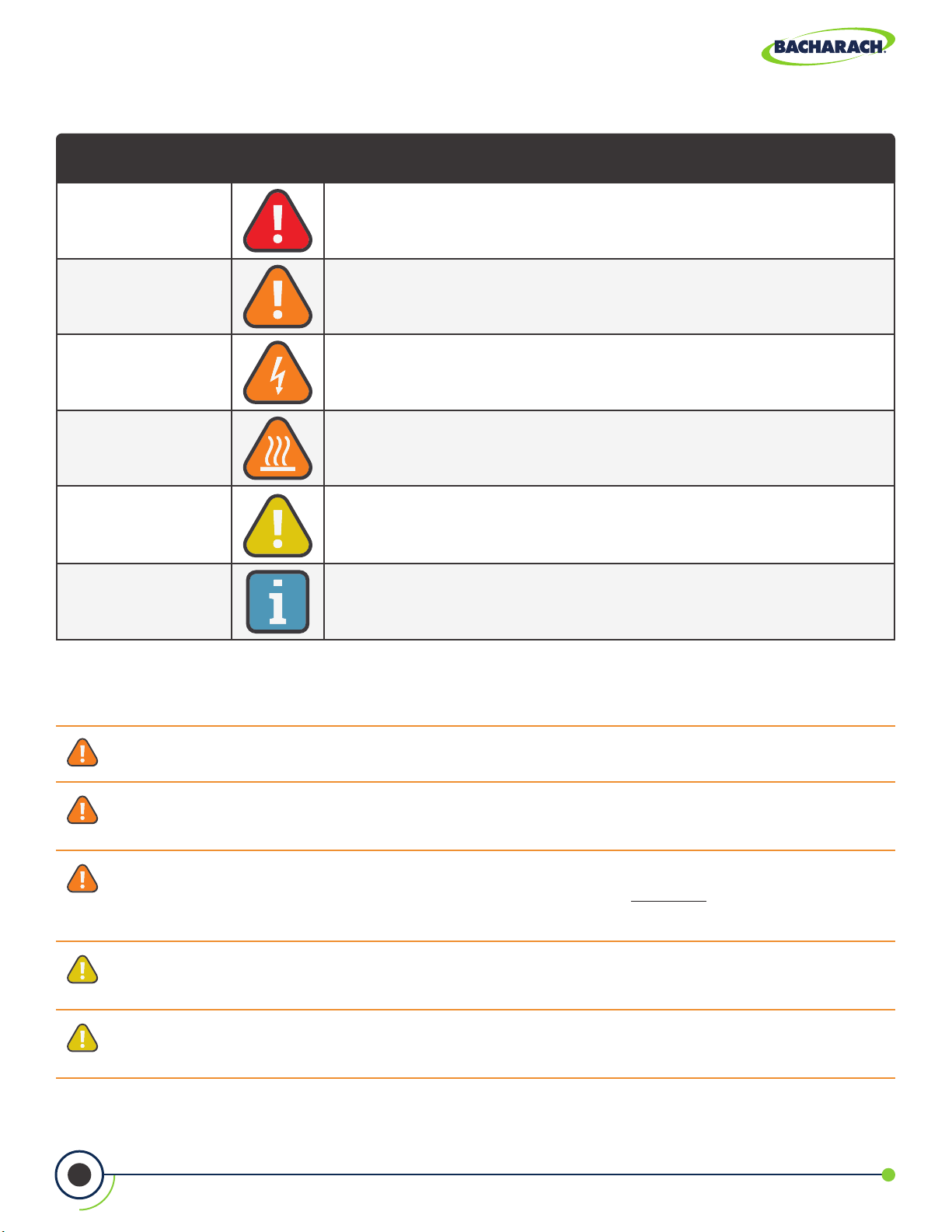
1.2.2 Iconography
Alert Icon Description
DANGER
WARNING
WARNING
WARNING
CAUTION
IMPORTANT
Imminently hazardous situation which, if not avoided, will result
in death or serious injury.
Potentially hazardous situation which, if not avoided, could
result in death or serious injury.
Potential electrical shock hazard which, if not avoided, could
result in death or serious injury.
Hot surface which, if not avoided, could result in physical injury
or damage to the product.
Potentially hazardous situation which, if not avoided, could result
in physical injury or damage to the product or environment. It
may also be used to alert against unsafe practices.
Additional information on how to use the product.
1.3 General Safety Statements
WARNING: This analyzer is not intended to be used as a safety device.
WARNING: When testing an appliance, a full visual inspection should be performed to
ensure its safe operation.
WARNING: This analyzer has not been designed to be intrinsically safe for use in areas
classied as being hazardous locations. For your safety, DO NOT use it in hazardous
(classied) locations.
CAUTION: This analyzer is designed for on-demand and / or semi-continuous sampling
and is not intended to be used on a continuous basis.
CAUTION: Do not store instrument or its sensors with solvents or products which
contain solvents.
7
0024-9551 Revision 2
Page 8

PCA® 400 User Manual
CAUTION: Except for sensor and battery replacement, this analyzer should only be
opened and / or serviced by authorized Bacharach personnel. Failure to comply may void
the warranty.
CAUTION: When the instrument is used in an inecient furnace or boiler application
where there is a high soot concentration, the probe’s sample lter may become
clogged. Before every use check the lter to conrm that it is clean or replace it with
a new lter.
CAUTION: Never disconnect the probe from the instrument until purging is complete.
Otherwise, leftover target gas (for example, CO) may remain in the probe and cause
inaccurate zeroing at power up that could lead to inaccurate gas measurements
afterwards.
1.4 Product Overview
The PCA® 400 is an industrial-grade, hand-held combustion and emissions analyzer
for on-demand and / or semi-continuous sampling of commercial and light industrial
appliances (furnaces, boilers and engines).
Standard Product Conguration
The base instrument is supplied with a probe and hose assembly, factory calibrated / installed
sensors, printer interface, hard carry case, lters, USB cable, PC Software (digital download),
AC adapter and a rechargeable lithium-ion battery pack. The reporting kit version (in addition
®
to the base) includes an IrDA + Bluetooth
printer and printer paper.
Intended Product Applications
The intended purpose of the measuring device is for:
• Engineerings servicing / monitoring industrial combustion plants process systems,
power stations
• Emissions inspectors, Engine manufacturers and operators, service engineers &
mechanics of burner /boiler manufacturers in the industrial sector.
®
Typical measuring tasks and particular characters of the PCA
400 include:
• Measurement on industrial engines (CO / NO dilution)
• Measurement on gas turbines (High precision CO and NO plus optional dilution).
• Emissions measurements (integrated ow speed and dierential pressure measurement)
The PCA® 400 has not been designed for and SHOULD NOT be used for the following:
• Continuous measurements over 5-hours
• As a safety (alarm) instrument.
8
0024-9551 Revision 2
Page 9
PCA® 400 User Manual
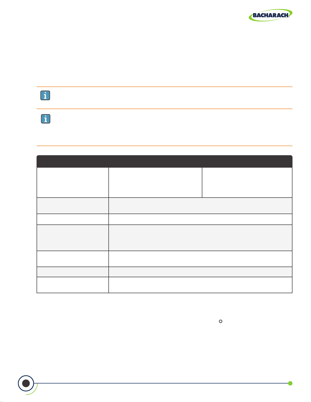
1.5 North American (NA) vs. Siegert (S)
Combustion Equations
Though the combustion process is fairly standardized across the globe, a combustion
analyzer intended for worldwide use demands a degree of exibility for a few regional
preferences.
IMPORTANT: Detailed dierences between North American and Siegert
congurations are noted where appropriate in this manual.
IMPORTANT: The Combustion Equations setting is used to congure the
instrument to use either North American combustion equations or Siegert
combustion equations. Changing this setting resets memory and the values of
other settings.
Feature North American (NA) vs. Siegert (S) Conguration
Countries
Heating Values
Fuels Dierent fuel sets and composition.
Dierent RUN
Parameters
Extra Siegert Parameters
CO
Max In the Siegert conguration, the user can set a CO2 Max number for the fuel.
2
Languages
®
The PCA
400 provides a North American (NA) conguration and a Siegert (S) conguration
Typical North American (NA) Users
Asia, Australia, Latin America,
North America, South America
For combustion calculations, Siegert uses the fuel’s lower heating value; NA
uses the higher value.
EFF (NA) vs. Stack loss and ETA (S)
Excess Air (NA) vs. Lambda (S)
(Lambda is similar to excess air)
CO/CO
displayed for Siegert only.
3 for the North American (NA) conguration and 8 for the Siegert (S)
conguration.
ratio, boiler temperature, smoke number, and oil derivative are
2
Typical Siegert (S) Users
Belgium, Denmark, France,
Germany, Italy, Netherlands,
Poland, Spain, United Kingdom
to address these and other needs, which are detailed in the table above.
f To change Combustion Equations: Main Menu Settings ( ) Combustion Eqns.
select Standard or Siegart (European).
9
0024-9551 Revision 2
Page 10
PCA® 400 User Manual
2. Product Description
2.1 Combustion & Emissions Analyzer ............................................................................... 11
2.1.1 Overview ......................................................................................................................................................11
2.1.2 Keypad .........................................................................................................................................................12
2.1.3 Display .........................................................................................................................................................12
2.1.4 Instrument Connections ............................................................................................................................14
2.1.5 Interfaces ....................................................................................................................................................15
2.1.6 Components ...............................................................................................................................................16
2.2 Sample Line & Probe Assembly ..................................................................................... 17
2.3 PowerCongurations ..................................................................................................... 18
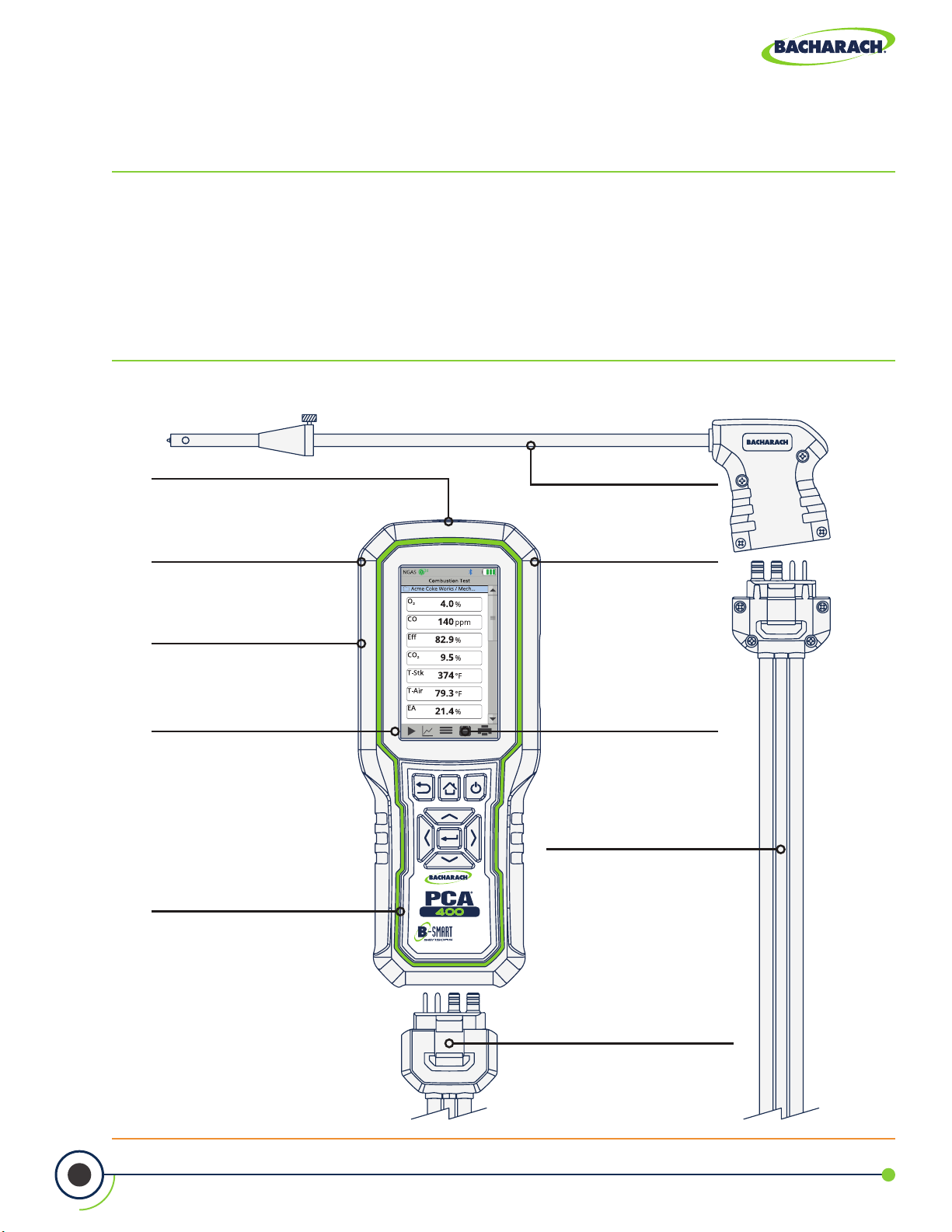
Fig. 2-1: Product Features
IrDA + Bluetooth® Communications
Wireless communications allow users to
conveniently stream data to printers and
compatible devices.
10 Standard Fuel Calculations
Combustion calculations for 10 common
fuel types and optional custom fuels.
4.3" Color Touch Display
Backlit display and resistive touch
make operation simple and intuitive
in the eld.
Enhanced Data Viewing
View data in list, tile or trending formats
making it easier to interpret results.
®
B-Smart
Pre-calibrated sensors eliminate
the need for costly down-time or
calibration gases.
Sensor Technology
Extended Probe Options
Probe assembly is available in 12",
The analyzer can be powered by a
rechargeable lithium-ion battery
pack, 4 × AA batteries or an AC
Stored analysis data can be
downloaded to a PC as a
Comma or Semicolon Separated
Sample Line Options
Sample line assembly is available with
Buna-N or Viton
in lengths of 7.5' and 15'.
24"and 36" lengths.
+
Hour Run Time
12
power adapter.
500 Memory Locations
Value (CSV) text le.
®
tubing construction
10
One-Step Connection
Keyed connectors ensure a quick, reliable
connection between the sample line
assembly and other components.
0024-9551 Revision 2
Page 11
PCA® 400 User Manual
2.1 Combustion & Emissions Analyzer
The PCA® 400 is designed for use in commercial and light industrial applications.
The analyzer is capable of measuring O2, CO, NO, NO2 or SO2, stack / ambient
temperatures, and pressure. The PCA® 400 also calculates CO2, NOx, combustion
eciency and excess air.
2.1.1 Overview
CAUTION: The analyzer contains strong magnets which may damage other
instruments. KEEP AWAY from products which could be damaged by magnetic
elds (e.g. monitors, computers, heart pacemakers, credit cards).
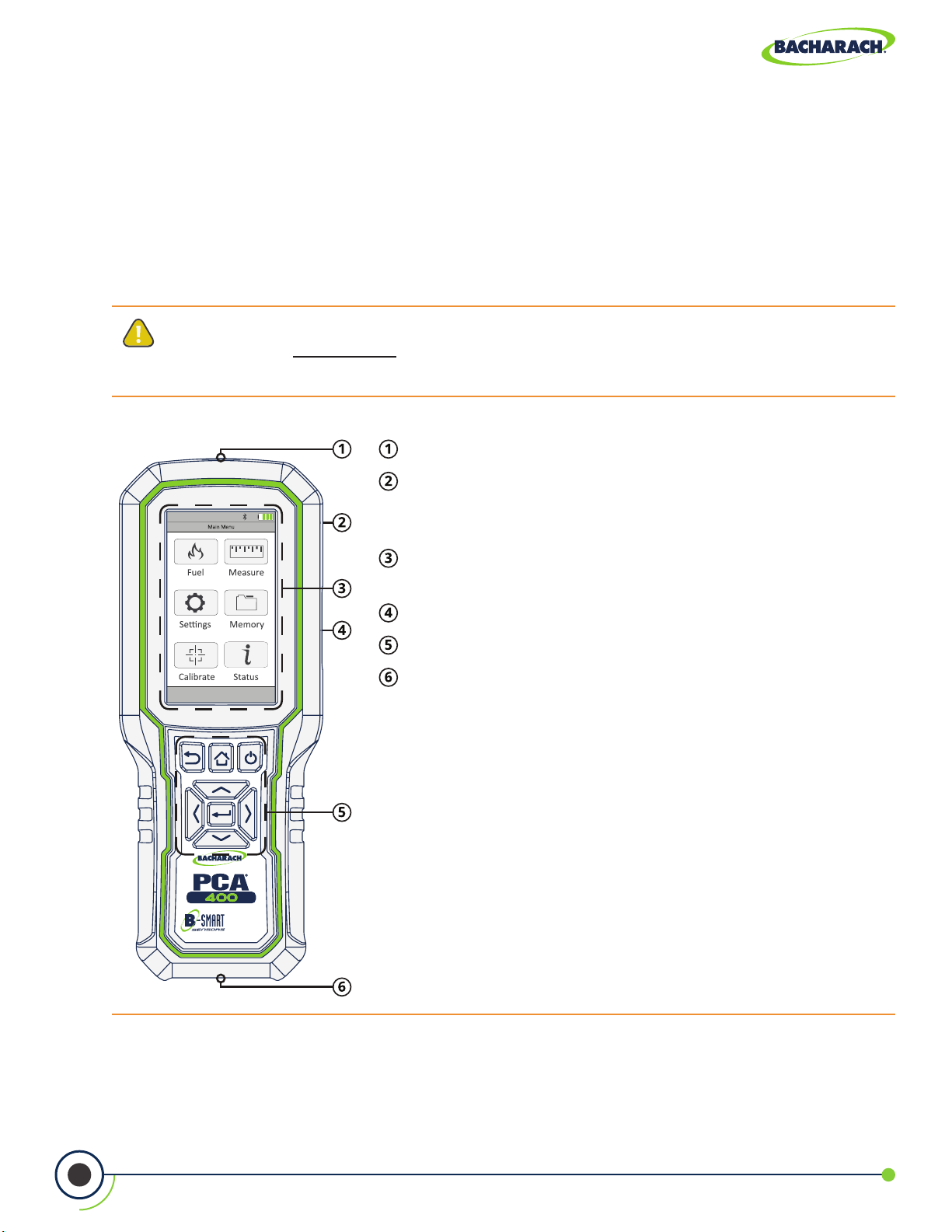
Fig. 2-2: Combustion & Emissions Analyzer
Infrared Printer Interface (top)
Integrated Magnetic Boot (rear) - High impact ABS
plastic with molded-in magnets protects the analyzer
and allows for hands-free use .
LCD Touch Display - 4.3" full color, backlit liquid-crystal
display with resistive touch panel.
Interfaces: USB, T-Air (side)
Tactile Keypad
Instrument Connections (bottom)
11
0024-9551 Revision 2
Page 12

PCA® 400 User Manual
2.1.2 Keypad
Fig. 2-3: Navigation Keypad
Back Key - Displays the previously viewed screen. In
addition, if changes have been made to one of the
analyzer’s operating parameters (e.g., date, time, O2
reference, etc.), pressing this button aborts any changes,
restores the old values and displays the previously
viewed screen.
Home Key - Displays the Main Menu. In addition, if
changes have been made to one of the analyzer’s
operating parameters (e.g., date, time, O2 reference, etc.),
pressing this button aborts any changes, restores the
old values and displays the Main Menu.
Power Key - Turns the analyzer ON and OFF.
Navigation Keys - Move the cursor on the display. When
viewing a directory, use the buttons to open and
close sub-directories.
2.1.3 Display
DANGER: Display contains liquid crystal which is poisonous. If liquid crystal comes
in contact with skin, wash immediately with soap and water. If ingested, immediately
contact the local poison control center.
CAUTION: DO NOT subject display to excessive shock.
CAUTION: Periodic cleaning with a lightly moistened soft cloth is recommended.
DO NOT wipe display with a dry cloth, as it may scratch the surface.
CAUTION: DO NOT use organic solvents or detergents to clean the display, as they
may cause damage to the screen.
Enter Key - Selects a highlighted item. In addition,
if changes have been made to one of the analyzer’s
operating parameter (e.g., date, time, O2 reference, etc.),
pressing this button conrms those changes and saves
them in memory.
12
0024-9551 Revision 2
Page 13
PCA® 400 User Manual
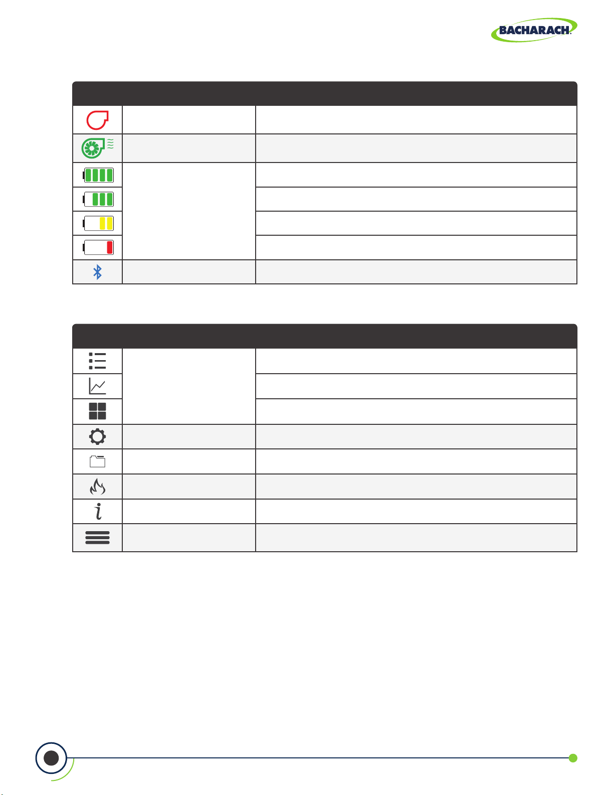
Status Icons
Icon Name Description
x
Battery / Power Status
Pump OFF Sample pump is idle
Pump ON Sample pump is operating
100% Charge
75% Charge
50% Charge
25% Charge
Bluetooth® Active Bluetooth® is enabled and compatible devices may be connected
Preference Icons
Icon Name Description
Display table / list format
Display Options
Display trending / line graph format
Display tile format
Settings Display conguration parameters
Memory Set le structure and naming conventions for data storage
Fuel Types Display list from which to select current test’s combustion fuel
Status Display device status, device information and main diagnostics
Options
Context-sensitive parameters; touch to adjust run/hold format,
low / high limits, features, options, etc.
13
0024-9551 Revision 2
Page 14
PCA® 400 User Manual
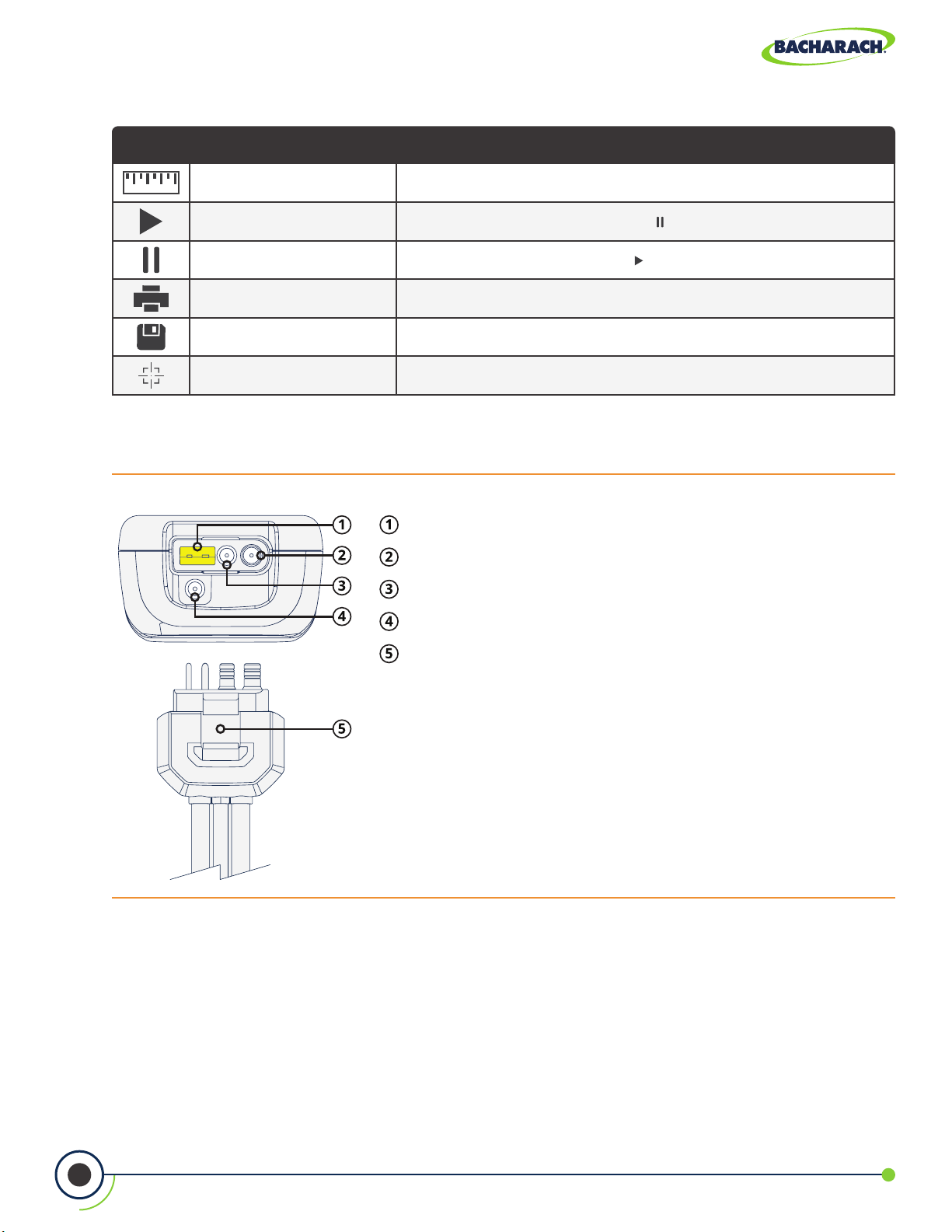
Function Icons
Icon Name Description
Measure Touch to select test to perform (combustion, pressure, temperature)
Turn On Pump Touch to turn on pump; used with to toggle RUN / HOLD mode
Stop Pump Touch to stop pump; used with to toggle RUN / HOLD mode
Print Touch to print data to IrDA + Bluetooth® printer
Save Touch to save data to default selected folder
Calibrate Touch to perform calibration functions
2.1.4 Instrument Connections
Fig. 2-4: Sample Line Connection Port
Stack Gas Type-K Thermocouple / T-STACK Port
Gas Sample Port
Pressure High Side (+∆P) Port
Pressure Low Side (-∆P) Port
Quick-Connector - keyed to t specic components:
gray analyzer, blue probe handle.
14
0024-9551 Revision 2
Page 15
PCA® 400 User Manual
2.1.5 Interfaces
Computer Interface
Data that has been stored in the analyzer’s onboard memory can be uploaded to a personal
computer by connecting the included Micro-B USB Cable between the USB ports of the
computer and the analyzer.
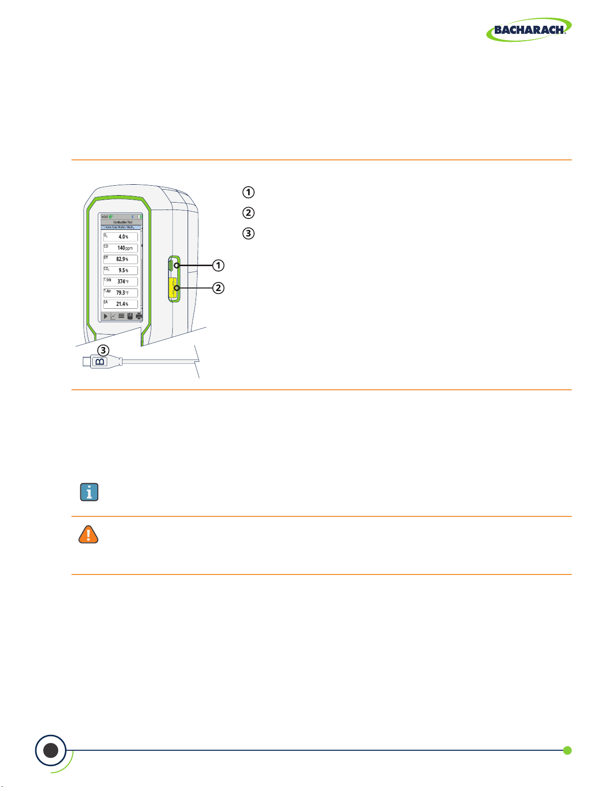
Fig. 2-5: Micro-B USB Port
Micro-B USB Port
Type-K Ambient Air Thermocouple / T-AIR Port
Micro-B USB Cable
Printer Interfaces
The PCA® 400 is capable of wirelessly transmitting data to compatible IrDA (Infrared Data
Associated) or IrDA + Bluetooth® Printers. The IrDA Interface is located at the top of the
device (Figure 2-2).
IMPORTANT: Interference can be caused by devices that are transmitting on the
same frequency band.
WARNING: Use of radio connection may not be permitted in some locations
(e.g. airplanes, hospitals). User assumes responsibility for complying with rules
governing the use of radio connections.
15
0024-9551 Revision 2
Page 16
PCA® 400 User Manual
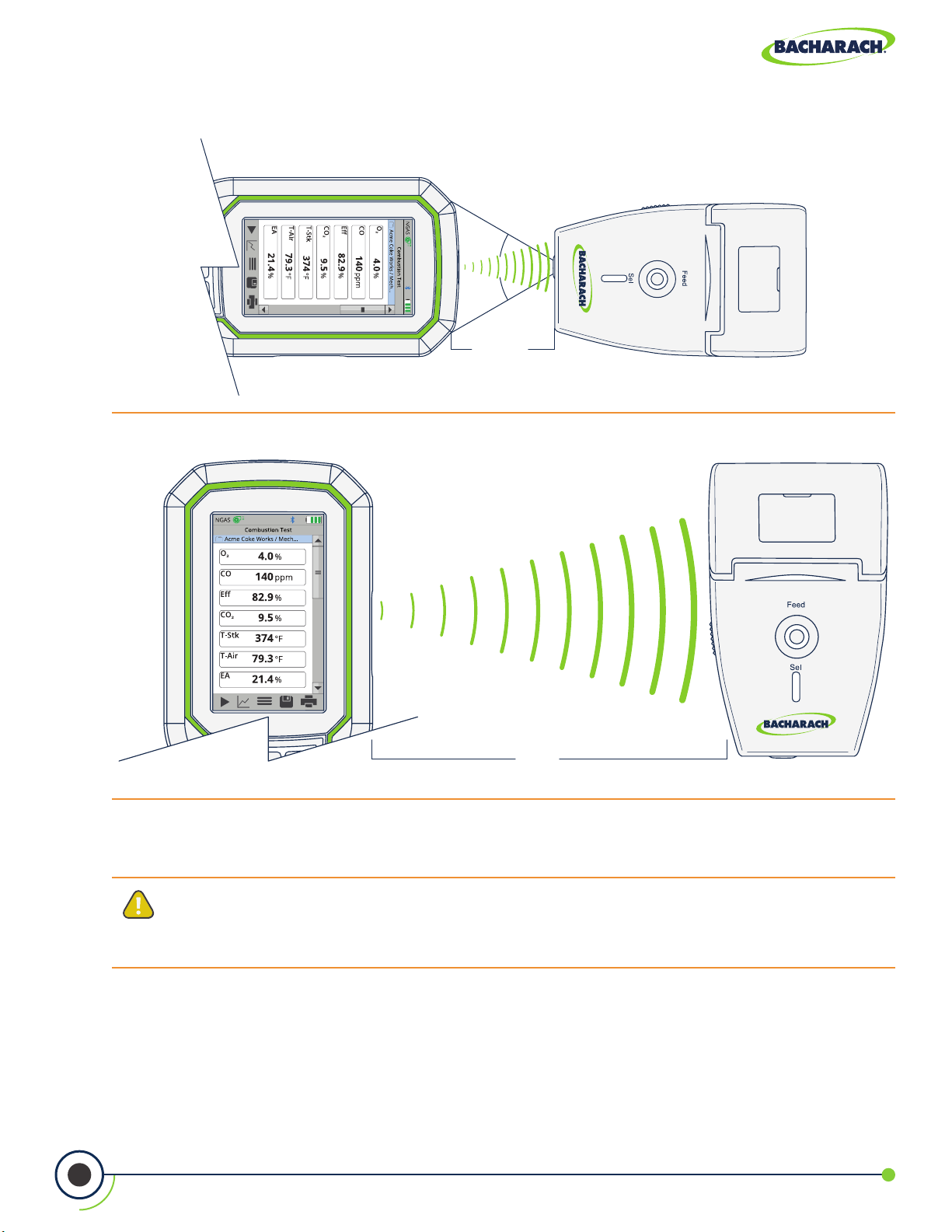
Fig. 2-6: IrDA Communication Range
Fig. 2-7: Bluetooth® Communication Range
60°
max.
4" to 16"
(10 to 30 cm)
2.1.6 Components
CAUTION: Except for sensor and battery replacement, this analyzer should only
be opened and / or serviced by authorized Bacharach personnel. Failure to comply
may void the warranty.
16
0024-9551 Revision 2
30'
(9.1 m)
Page 17
PCA® 400 User Manual
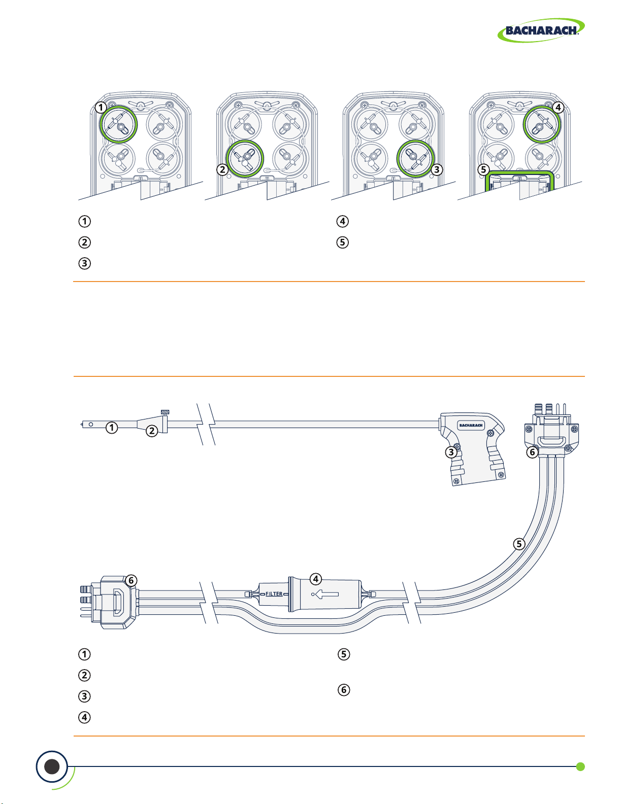
Fig. 2-8: Sensor & Battery Positions
Sensor Position 1 - O
Sensor Position 2 - CO
2
LOW
or CO
Sensor Position 3 - NO2 or SO
HIGH
2
Sensor Position 4 - NO
Battery Compartment
2.2 Sample Line & Probe Assembly
The PCA® 400’s sample line and probe are modular, allowing users to quickly swap
out dierent sized probe lengths, sample lines and the optional sample conditioner.
Fig. 2-9: Sample Line & Probe Assembly
17
Probe Tube - available in multiple lengths.
Probe Stop
Probe Handle
Water Trap / Filter Assembly
0024-9551 Revision 2
Sample Line - available in multiple
lengths and construction types.
Quick-Connector - keyed to t specic
components: gray analyzer, blue probe
handle.
Page 18
PCA® 400 User Manual
IMPORTANT: Replacement parts and accessories are sold separately. See Part
Numbers (Section 7.1) for more information.
2.3 Power Congurations
The PCA® 400 comes standard with a rechargeable lithium-ion battery pack which is
capable of powering the analyzer for up to 12-hours. Users may also run the analyzer
on 4 × AA batteries or via the supplied Micro-B USB cable and AC power adapter.
WARNING: DO NOT disassemble battery pack or short battery contacts, as this
may result in electrical shock.
DANGER: Batteries may pose risk of explosion, re or chemical burns if mistreated:
• NEVER dispose of batteries in a re or incinerator.
• NEVER expose batteries to corrosive liquids.
• DO NOT attempt to charge batteries which are swollen or bulging.
CAUTION: Lithium-Ion batteries contain elements that may pose health risks to
individuals if they are allowed to leach into the ground water supply. Always dispose
of batteries in accordance with local regulations.
IMPORTANT: Operating the analyzer with the AC power adapter DOES NOT charge
its rechargeable batteries. To recharge the analyzer’s batteries, supply power via
the AC power adapter when the analyzer is turned OFF.
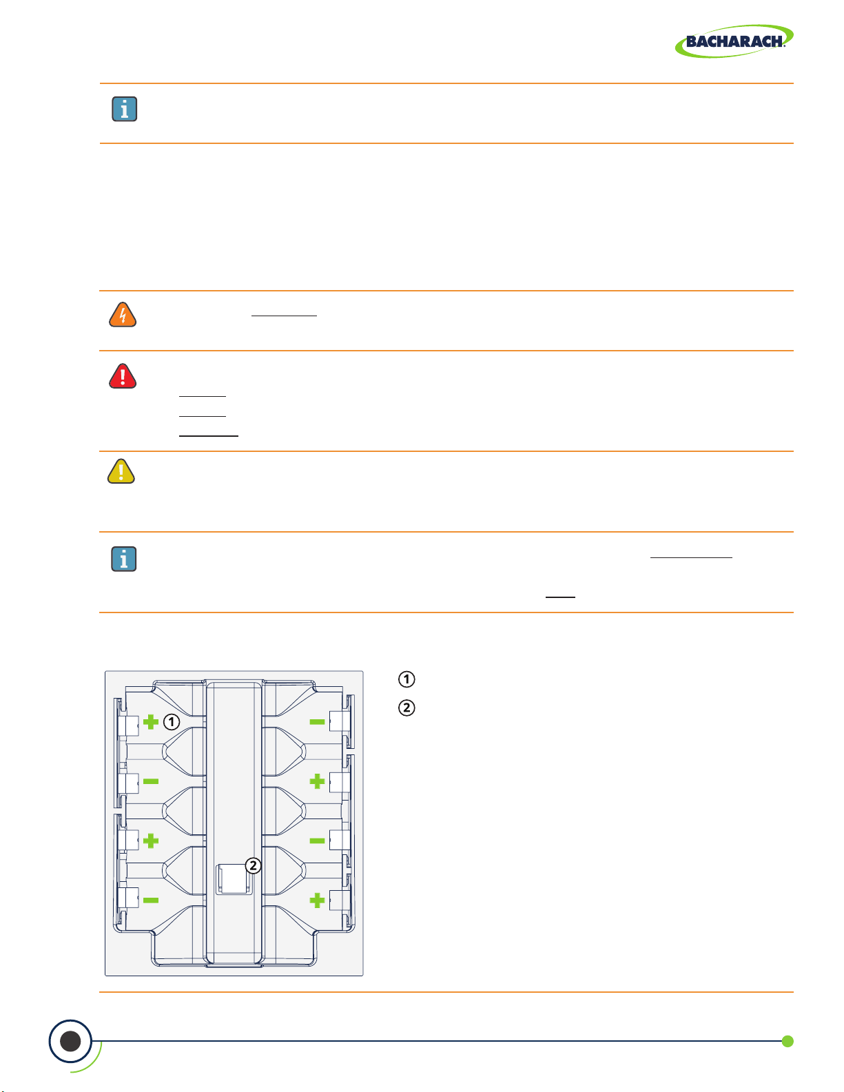
Fig. 2-10: Congurations for Li-ion Battery Pack and 4 × AA Batteries
AA Battery Tray
Li-ion Battery Pack Connection
18
0024-9551 Revision 2
Page 19

PCA® 400 User Manual
3. Operation
3.1 Setup ................................................................................................................................ 19
3.1.1 Operation Tips ............................................................................................................................................19
3.1.2 Inspection / Prerequisites ..........................................................................................................................21
3.1.3 Connecting Probe Assembly ......................................................................................................................22
3.2 Performing Combustion Test ....................................................................................... 23
3.2.1 Combustion User Preferences ..................................................................................................................23
3.2.2 Combustion Analysis .................................................................................................................................24
3.2.3 Additional Settings .....................................................................................................................................27
3.2.4 Combustion Average Test ..........................................................................................................................31
3.3 Performing Pressure Test ............................................................................................. 32
3.3.1 Pressure User Preferences ........................................................................................................................32
3.3.2 Pressure Analysis ........................................................................................................................................32
3.4 Performing Leak Tests (Siegert Only) ............................................................................ 34
3.4.1 Let-by Test ..................................................................................................................................................34
3.4.2 Tightness Test .............................................................................................................................................35
3.5 Performing Temperature Test ..................................................................................... 36
3.4.1 Temperature User Preferences .................................................................................................................36
3.4.2 Temperature Analysis ................................................................................................................................37
3.1 Setup
Properly preparing the analyzer is critical to accurate analysis and safe operation. Be
sure to read the following instructions prior to use of this instrument.
3.1.1 Operation Tips
Allow Analyzer to Warm-up Slowly
When an analyzer is brought in from a cold vehicle, allow it to warm-up slowly to minimize
condensation. Temperatures below freezing will not damage the analyzer.
CAUTION: Although the analyzer itself is not damaged by extremely cold
temperatures, the electrochemical sensors may sustain damage. The O2 sensor’s
electrolyte will freeze at approximately -13ºF (-25ºC), and the other sensors at
approximately -94ºF (-70ºC). If the analyzer is exposed to extremely cold conditions,
it is strongly suggested that the sensor housings be examined for hairline cracks.
Be aware that a leaking sensor can cause chemical burns to the skin and possibly
damage the surrounding PCB assemblies.
19
0024-9551 Revision 2
Page 20
PCA® 400 User Manual
Start Analyzer in Fresh Air
Ensure that the analyzer is sampling fresh air during initial 60-second warm-up period.
Pulling a stack gas sample through the analyzer during its warm-up period will not damage
the analyzer, but it will result in incorrect sensor readings, and may result in sensor error
messages appearing after the warm-up cycle completes.
Inspect Water Trap / Filter Assembly
Before each use, inspect the lter element of the water trap / lter assembly. Replace the
lter if it looks dirty. See Replacing the Filter Element (Section 5.2) for more information.
Keep Analyzer Above Water Trap Assembly
When sampling ue gas, keep the analyzer above the water trap, and keep the trap in a
vertical position. This will maximize the eectiveness of the trap and keep liquid condensate
from being drawn directly into the analyzer. (Flue gas condensate can be acidic and very corrosive.
Do not to allow the analyzer’s internal components to come in contact with condensate.)
Don’t Allow Water Trap to Become Full
When liquid condensate is seen inside the water trap, empty the trap before it becomes full.
See Emptying the Water Trap (Section 5.1) for more information.
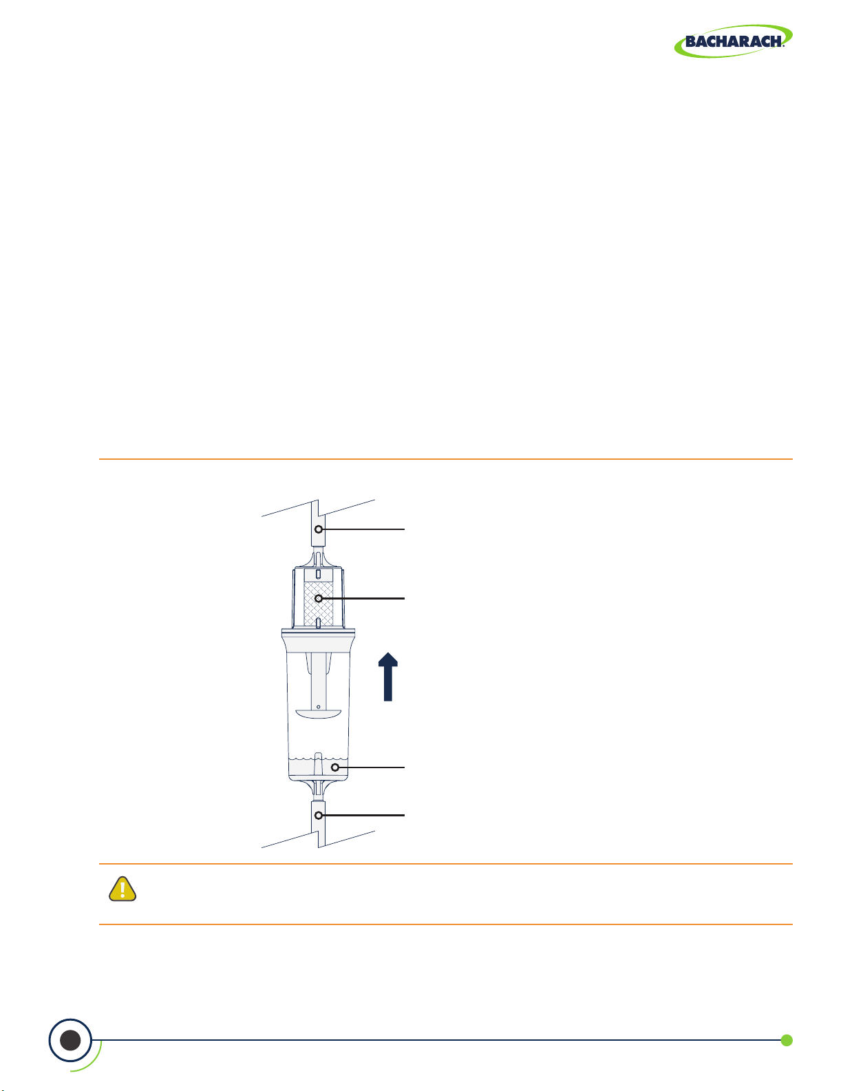
Fig. 3-1: Water Trap / Filter Assembly
To Gas Port on Analyzer
Ensure that lter is clean.
Never allow the water level
to rise above tip of riser tube
during operation.
Stack Gas from Probe
20
CAUTION: Use the Water Trap / Filter Assembly in a vertical position with the gas
ow arrow pointing up as shown in the illustration above.
0024-9551 Revision 2
Page 21
PCA® 400 User Manual
Purge Analyzer After Each Use
The analyzer should be purged after performing a combustion test. After removing probe
from the stack, let the pump run for at least 10-minutes to remove any stack gases and dry
any condensate from inside the sensor chamber and probe assembly.
Remove Moisture from Water Trap Before Storing
When storing the analyzer, it is recommended that users empty the water trap and leave it
open to prevent damage associated with prolonged exposure to moisture. See Emptying
the Water Trap (Section 5.1) for more information.
Maintain Sensor Calibration
Calibrate the analyzer every 6-months to 1-year to ensure its accuracy. See Calibration
(Sections 5.5 and 5.6) for more information.
3.1.2 Inspection / Prerequisites
Before performing any tests with the analyzer, verify the following:
Thewatertrap/lterassemblyisempty,clean,andthearrowispointingUP.
Check for obvious signs of splits and or cracks in the sample line and other tubing.
Perform routine maintenance (replacing sensors, calibrating, etc.) as outlined in Care &
Maintenance.
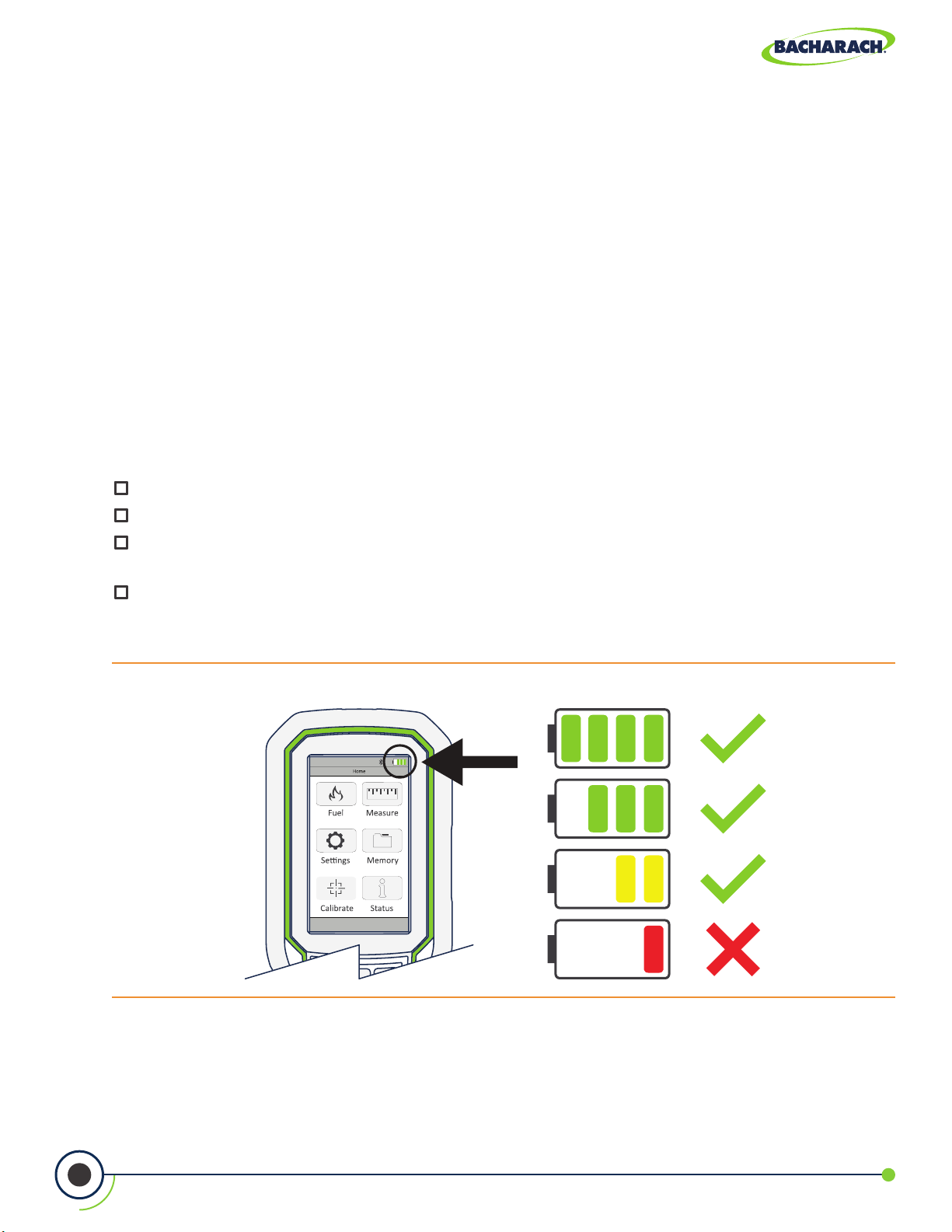
Ensurethattheanalyzerhassucientchargebeforeoperation.Ifindoubt,recharge
Li-ion battery pack, replace disposable batteries or provide power via the AC adapter
and USB cable.
Fig. 3-2: Acceptable Battery Levels
21
0024-9551 Revision 2
Page 22
PCA® 400 User Manual
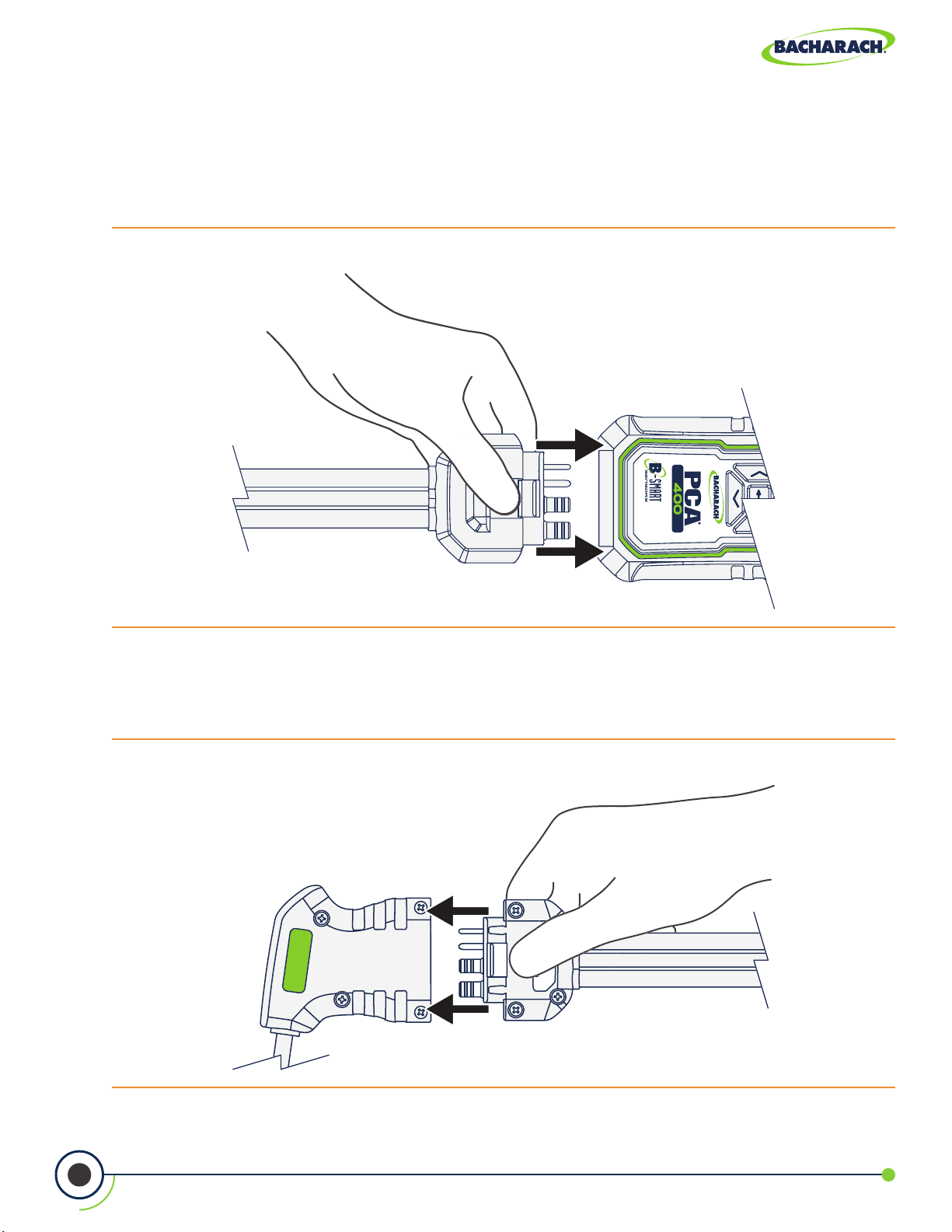
3.1.3 Connecting Probe Assembly
1. Connect Analyzer to Sample Line
Firmly insert the gray quick-connector into the base of the analyzer. Users will hear a click
once a secure connection has been made.
Fig. 3-3: Insert Gray Quick-Connector into Analyzer
2. Connect Probe to Sample Line
Firmly insert the blue quick-connector into the base of the probe handle. Users will hear a
click once a secure connection has been made.
Fig. 3-4: Insert Blue Quick-Connector into Probe Handle
22
0024-9551 Revision 2
Page 23
PCA® 400 User Manual
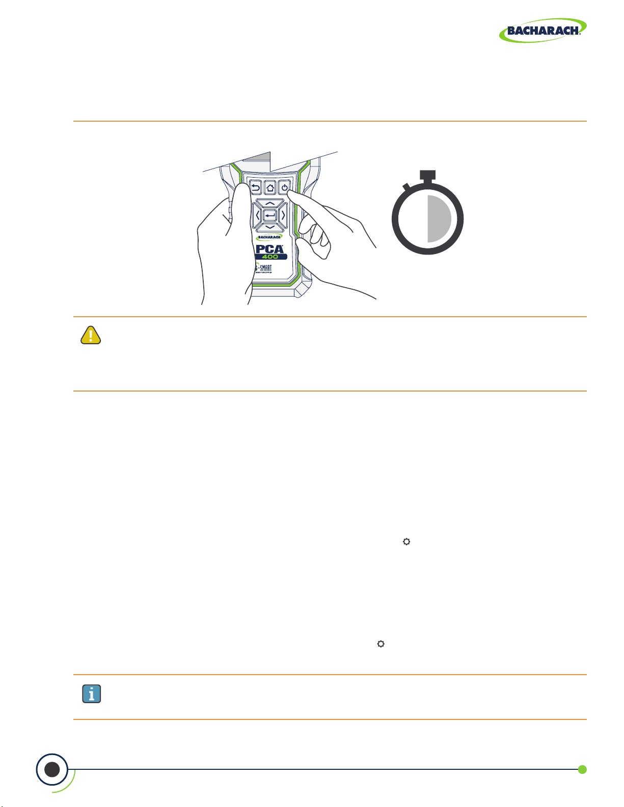
3. Turn On Analyzer
Press the POWER button to begin a 60-second warm-up period. Users will hear the pump
begin operation and splash screen should appear on the analyzer’s display.
Fig. 3-5: Press Power Button
60-SECOND
WARM-UP
CAUTION: Ensure that the analyzer is sampling fresh air during the warm-up.
Pulling a stack gas sample through the analyzer during its warm-up period will not
damage the analyzer, but it will result in incorrect sensor readings, and may result
in sensor error messages appearing after the warm-up cycle completes.
3.2 Performing Combustion Test
3.2.1 Combustion User Preferences
Temperature Units
Select to display temperature in Fahrenheit (ºF) or Celsius (ºC).
f To change Temperature Units: Main Menu Settings ( ) Temperature Units select
Fahrenheit or Celsius.
Pollution Units
®
The PCA
to various pollution units using CFR40 Part 60 emission factors. (Note that the pollution unit
conversions for NO, NO2 and NOx are based on the molecular weight of NO2.)
400 is capable of converting the measured ppm levels of CO, NO, NO2, and SO2
23
f To change Pollution Units: Main Menu Settings ( ) Pollution Units select ppm, lb/
MBtu, mg/m3 or g/GJ.
IMPORTANT: After saving changes to Temperature and Pollution Units, they will
become the analyzer’s default values for all future testing.
0024-9551 Revision 2
Page 24
PCA® 400 User Manual
3.2.2 Combustion Analysis
1. Select Folder / Memory Location (User Discretion)
®
The PCA
viewing and downloads.
f To change Folder / Memory Location: Main Menu Memory ( ) use navigation keys
to highlight the desired folder Options (
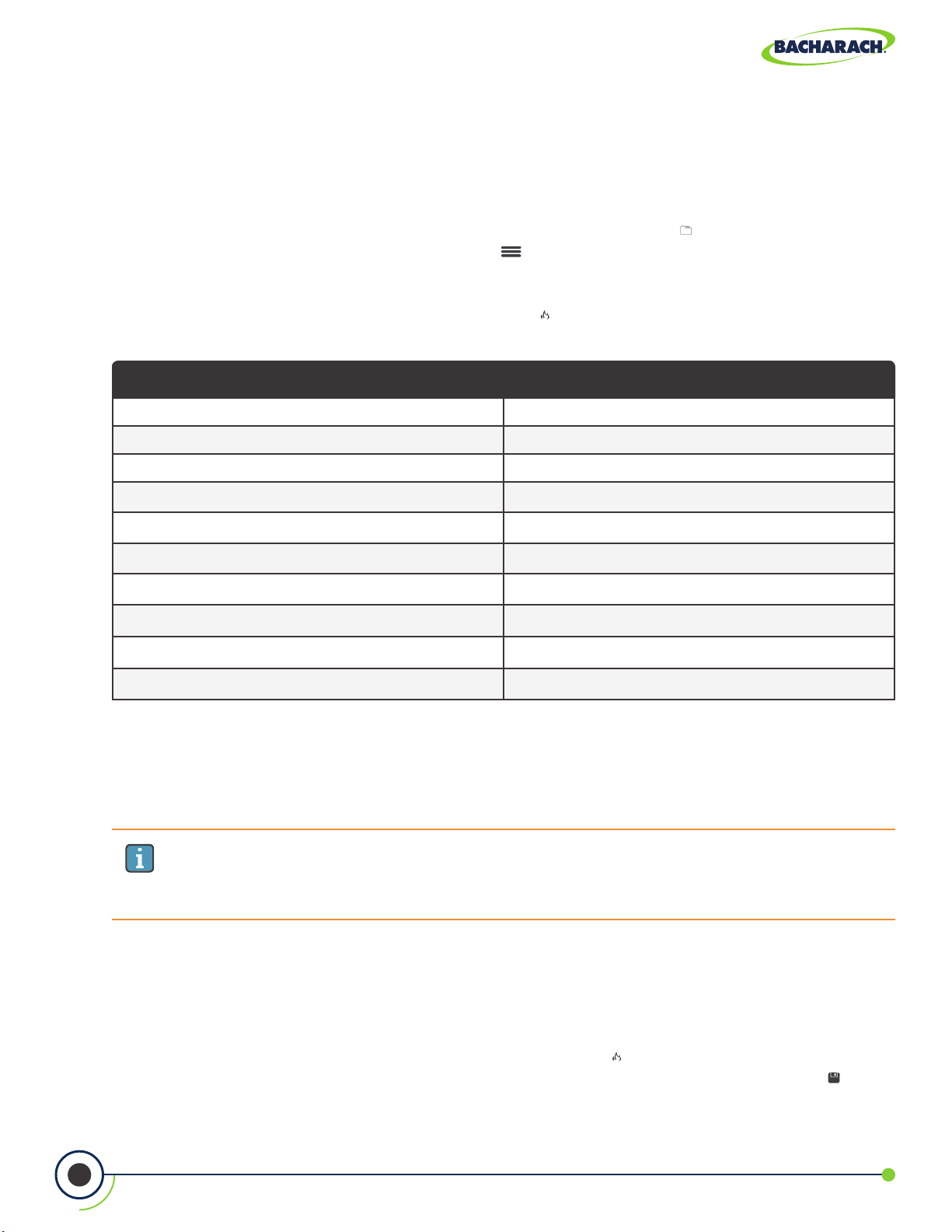
2. Select Fuel Type
400 gives users the ability to organize their records in a folder structure for later
) select Target.
f To select Fuel Type: Main Menu Fuel Menu (
) select the fuel used in the application
being tested.
NA (Standard) Siegert
Natural Gas Natural Gas
Oil #2 KOKS
Oil #4 LEG
Oil #6 Propane
Propane Oil #2
Coal Oil #6
Wood Coal
Kerosene BioFuel
Bagasse LPG
Digester Gas Butane
If your combustion application requires a fuel type not listed in the Fuel menu, contact
Bacharach for information on additional fuel codes. Custom fuel codes may developed by
Bacharach at a customer’s request and can be loaded into the instrument using the PCA
Reporting Software.
IMPORTANT: Custom fuel codes are specific to the combustion equations that
are being used, so be sure to include your combustion equation type (North
American or Siegert) with any custom fuel code requests.
3. CO2 Max Value (Siegert Only)
When using the PCA® 400’s Siegert conguration, additional settings allow one to adjust the
CO2 max value to account for fuel variations. Adjusted CO2 Max values are stored with the
saved combustion records and
f To change the CO2 Max: Main Menu Fuel Menu ( ) select the fuel used in the
application being tested Adjust insert the desired CO2 Max press Save ( ).
24
0024-9551 Revision 2
Page 25
PCA® 400 User Manual
4. Select Measurement Type
f To select Measurement Type: Main Menu Measure (
) select Combustion.
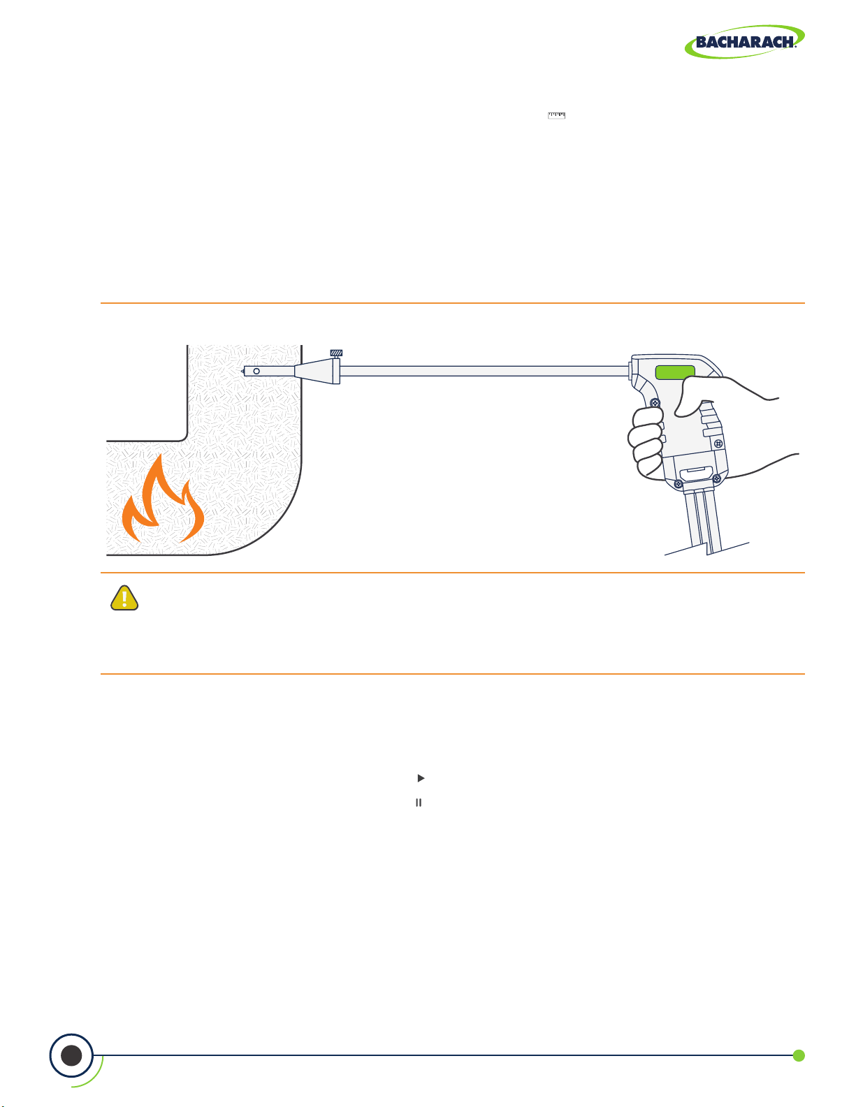
5. Insert Probe Tube into Measurement Area
After identifying the ue / exhaust stack, select a safe and convenient location from which
to draw the sample.
f Select length-appropriate probe.
f Set probe stop to ensure that the probe is inserted into the center of the ue / exhaust
stack / measurement area. (The probe stop also acts to secure the probe in the measurement
area during analysis.)
Fig. 3-6: Probe Placed in Center of Measurement Area
CAUTION: When the instrument is used in an inecient furnace or boiler application
where there is a high soot concentration, the probe’s sample lter may become
clogged. Before every use check the lter to conrm that it is clean or replace it with
a new lter (Section 5.2).
6. Run Sample Pump
After starting the pump, allow readings to stabilize for a minimum of 3-minutes or as long
as required by manufacturer specications / compliance testing procedures.
f To start the pump: press Run / Hold (
).
f To stop the pump: press Run / Hold ( ).
25
0024-9551 Revision 2
Page 26

PCA® 400 User Manual
Fig. 3-7: Combustion Test Screen
NGAS
Combustion Test
Acme Powerplant
Fuel Type - displays fuel calculation being used to
produce combustion data.
Pump Status - ( ) indicates that the pump is on,
( ) indicates that the pump is off.
Folder / Memory Location - location where
combustion data will be saved.
Combustion Data - results from combustion
analysis; display can be toggled by pressing (
).
Run / Hold - toggle sample pump operation; press ( )
to run and (
) to pause.
Toggle View - change data display between table /
list ( ), line graph ( ), tile ( ) formats.
Options - displays additional settings / conguration
(Fresh Air Purge, Logging, Pump Speed, Run / Hold Format,
Line Graph Settings, O2 Reference, Zoom, NOx Calculation).
Save - save combustion data to the selected folder /
memory location.
Print - print combustion data to IrDA / Bluetooth®
printer(s).
7. Save / Print Readings
®
The PCA
400 is capable of saving active data to the analyzer’s onboard storage and / or
printing to the optional IrDA / Bluetooth® printer.
f To save combustion readings / report: press Save ( ).
f To print combustion readings / report: press Print ( ).
IMPORTANT: Printing via Bluetooth® is diabled when the analyzer is connected to
the PCA® 400 App. If you wish to print, disconnect from the mobile app or enable
IrDA communications.
26
0024-9551 Revision 2
Page 27

PCA® 400 User Manual
)1
)1
CAUTION: The probe MAY BE HOT after analysis and can cause bodily harm and /
or damage to the analyzer. Allow the probe sucient time (about 5-minutes) to cool
before handling or storing in the supplied carrying case.
CAUTION: Never disconnect the probe from the instrument until purging is
complete. Otherwise, leftover target gas (for example, CO) may remain in the
probe and cause inaccurate zeroing at power up that could lead to inaccurate gas
measurements afterwards.
CAUTION: The probe and sample line may become dirty during normal use and
should be cleaned regularly to ensure proper function. See Cleaning the Probe
Assembly (Section 5.3) for more information.
3.2.3 Additional Settings
Data Display Options
Data can be viewed in list (text), tile and trending formats allowing users to easily analyze
their combustion analysis results. Users can further customize the PCA® 400 to show all the
parameters in the order they prefer.
f To toggle between Display Options: Display Options ( ) select Table / List Format ( ),
Line Graph Format ( ) or Tile Format ( ).
Fig. 3-8: Table / List, Line Graph and Tile Formats
NGAS
Combustion Test
Acme Powerplant
OIL2
Combustion Test
Acme Powerplant
500
CO (ppm)O
0
21
)
%
(
2
Time (min
NGAS
Combustion Test
Acme Powerplant
O
2
CO
Eff
CO
2
T-Stk
4.0
140
82.9
9.5
374
%
ppm
%
%
°F
27
0
0024-9551 Revision 2
Time (min
T-Air
EA
79.3
21.4
°F
%
Page 28
PCA® 400 User Manual
Zoom (List View)
Combustion test data can be shown with enlarged characters to make viewing easier.
The operator can set zoom levels to STANDARD or LARGE. The Standard zoom setting
will display fteen (15) lines of combustion test data at one time and the Large zoom
setting will display twelve (12) lines of combustion test data with enlarged characters. The
operator can scroll through the complete list of measured and calculated data no matter
what zoom level has been selected.
f To update Zoom: Options ( ) Zoom select Standard or Large.
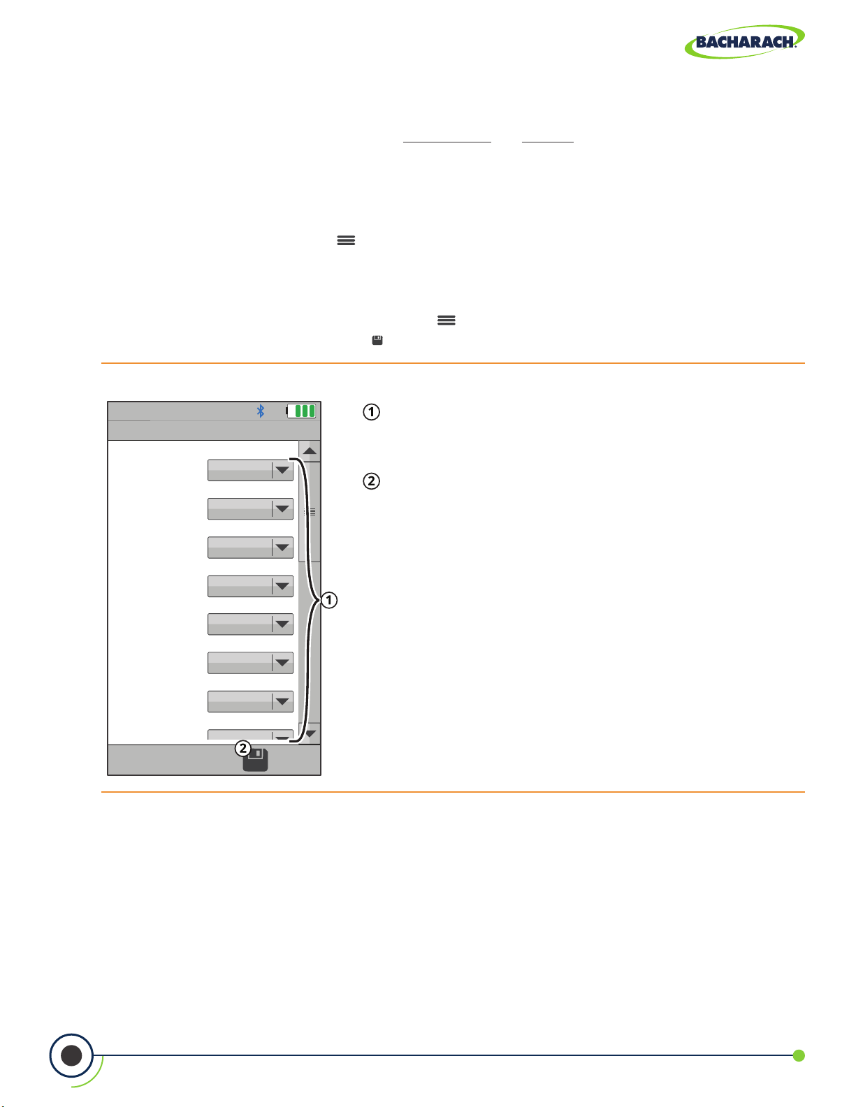
Run / Hold Format (List View)
The analyzer allows users to customize the order in which analysis results are displayed.
f To update Run / Hold Format: Options (
dropdown menu press Save (
).
Fig. 3-9: Run / Hold Format
Analysis Positions - use the dropdown menu to
Run/Hold Format
customize the order in which analysis results are
displayed in the List View.
Position 1O
Position 2CO
Position 3EA
Position 4CO
Position 5T-Stack
Position 6T-Air
Position 7Flow
Save - save Run / Hold Format and return to current
combustion analysis results.
) Run / Hold Format set prioritization via
28
Position 8None
0024-9551 Revision 2
Page 29

PCA® 400 User Manual
Combustion Test Parameters NA (Standard) Siegert
Oxygen O
2
O
2
Carbon Monoxide CO CO
Excess Air EA Lambda
Eciency Using Higher Heating Value E E
Carbon Dioxide CO
2
CO
2
Setting for Maximum Carbon Dioxide in Flue Gas ― CO2 Max
Stack Temperature T-Stk T-Stk
Ambient Air Temperature T-Air T-Air
Stack Loss ― qA
Eciency Using Lower Heating Value ― Eta
Carbon Monoxide/Carbon Dioxide Ratio ― CO/CO
CO Referenced to O2 Percentage n CO (n) CO (n)
Pump Flow Rate Flow Flow
Nitric Oxide NO NO
Nitrogen Dioxide NO
2
NO
2
2
Oxides of Nitrogen NO
Sulfur Dioxide SO
x
2
NO
SO
x
2
NO Referenced to O2 Percentage n NO (n) NO (n)
NO
Referenced to O2 Percentage n NO2 (n) NO2 (n)
2
NO
Referenced to O2 Percentage n NOx (n) NOx (n)
x
SO
Referenced to O2 Percentage n SO2 (n) SO2 (n)
2
Average of 3 Smoke Numbers (Manually Entered) ― Avg Smoke
Presence of Oil Derivatives (Manually Entered) ― Oil Derive
Boiler Temperature (Manually Entered) ― Boiler Temp
29
0024-9551 Revision 2
Page 30

PCA® 400 User Manual
Line Graph Settings (Trending View)
The analyzer allows users to customize the order in which analysis results are displayed.
f To update Line Graph Settings: Options (
time via dropdown menu press Save (
Fig. 3-10: Line Graph Settings
Parameter 1 - value of the top graph’s y-axis; choose
Line Graph Settings
from None, O2, CO, NO, NO2, SO2,T-AIR, T-STK, E,
EA, CO2, NOx, CO(0), NO (0), NO2(0), NOx(0) or SO2(0).
Parameter 1O
Parameter 2CO High
Parameter 2 - value of the bottom graph’s y-axis;
choose from None, O2, CO, NO, NO2, SO2,T-AIR, T-STK,
E, EA, CO2, NOx, CO(0), NO (0), NO2(0), NOx(0) or SO2(0).
Time 30 seconds
Time - value of each of the graph’s x-axis; choose
from 30-seconds, 1-minute, 3-minutes, 5-minutes
and 15-minutes.
Save - save Line Graph Settings and return to
current combustion analysis results.
) Line Graph Settings set parameters &
).
Pump Speed
The sample pump is capable of operating at two dierent rates; allowing users to
compensate for longer lengths of sample line or to overcome higher draft in the
measurement area.
f To change Pump Speed: Options (
) Pump Speed select Standard or High.
IMPORTANT: Operating the analyzer at a higher pump rate consumes more power
and will reduce the expected battery life.
IMPORTANT: Changes to this setting will not become the analyzer’s default
value for future testing. When restarting, the analyzer will revert to STANDARD
pump rate.
30
0024-9551 Revision 2
Page 31

PCA® 400 User Manual
3.2.4 Combustion Average Test
1. Select Folder / Memory Location (User Discretion)
®
The PCA
viewing and downloads.
f To change Folder / Memory Location: Main Menu Memory ( ) use navigation keys
to highlight the desired folder Options (
2. Select Measurement Type
400 gives users the ability to organize their records in a folder structure for later
) select Target.
f To select Measurement Type: Main Menu Measure (
) select Combustion Average.
3. Set Duration / Interval of Testing
f Select duration and interval of test: Select desired Duration and Interval from dropdown
menus press Save (
Combustion Average Durations
1-minute
2-minutes
5-minutes
10-minutes
15-minutes
20-minutes
30-minutes
1-hour
).
Combustion Average Intervals
1-second
10-seconds
30-seconds
1-minute
4. Insert Probe Tube into Measurement Area
After identifying the ue / exhaust stack, select a safe and convenient location from which
to draw the sample.
f Select length-appropriate probe.
f Set probe stop to ensure that the probe is inserted into the center of the ue / exhaust
stack / measurement area. (For more information on the placement of the sample probe, see
Figures 3-6.)
5. Run Sample Pump
After starting the pump, the analyzer will stabilize for 180-seconds before beginning the
combustion average test.
f To start the pump: press Run / Hold (
).
f To stop the pump: press Run / Hold ( ).
31
0024-9551 Revision 2
Page 32

PCA® 400 User Manual
7. Save / Print Readings
The PCA
printing to the optional IrDA / Bluetooth
®
400 is capable of saving active data to the analyzer’s onboard storage and / or
®
printer.
f To save combustion readings / report: press Save (
f To print combustion readings / report: press Print (
3.3 Performing Pressure Test
3.3.1 Pressure User Preferences
Pressure Units
Select to display pressure in Inches of Water Column (inwc), Millibar (mB), Pascal (Pa), HectoPascal (hPa) or Millimeters of Water Column (mmwc).
f To change Pressure Units: Main Menu Settings (
InchesWater, milliBar, Pascals, HectoPascals or mmH20.
3.3.2 Pressure Analysis
1. Select Folder / Memory Location (User Discretion)
The PCA® 400 gives users the ability to organize their records in a folder structure for later
viewing and downloads.
).
).
) Pressure Units select
f To change Folder / Memory Location: Main Menu Memory (
to highlight the desired folder Options (
2. Select Measurement Type
f To select Measurement Type: Main Menu Measure (
3. Zero Pressure Sensor (User Discretion)
Before taking a measurement, the pressure sensor may need to be re-zeroed if it is not
already displaying zero with both pressure ports open to the atmosphere.
f If necessary, zero the pressure sensor: Press Zero (
f Disconnect hoses and press OK to zero the pressure sensor.
f Reconnect hoses. When measuring draft, leave the -∆P port open to the atmosphere
and connect the probe’s draft hose to the + ∆P port.
) select Target.
) select Pressure.
).
) use navigation keys
32
0024-9551 Revision 2
Page 33

PCA® 400 User Manual
Fig. 3-13: Pressure Connection Ports
4. Insert Probe Tube into Measurement Area
After identifying the ue / exhaust stack, select a safe and convenient location from which
to take measurements.
f To measure draft: insert the probe tube into the ue / exhaust stack / measurement
area and observe the reading on the Pressure screen.
f To measure dierential pressure: connect sampling hoses to the +∆P and -∆P ports
and place the ends of the hoses into the measurement areas being compared. The
dierential pressure between the two areas will be displayed on the Pressure screen.
The dierential pressure reading will be positive if the pressure at the +∆P is higher than
that read at the -∆P and negative if it is lower than that read at the -∆P.
Pressure High Side (+∆P) Port
Pressure Low Side (-∆P) Port
Fig. 3-14: Pressure Test Screen
Pressure
Acme Powerplant
Delta P
0.05 inwc
Selected Folder / Memory Location - location where
data will be saved.
DierentialPressure- measured dierence between
Pressure High Side (+∆P) and Pressure Low Side (-∆P).
Zero Button - press to zero (calibrate) pressure
reading to ambient pressure.
Save - save pressure data to the selected folder /
memory location.
Print - print pressure data to IrDA / Bluetooth
®
printer(s).
33
0024-9551 Revision 2
Page 34

PCA® 400 User Manual
5. Save / Print Readings
®
The PCA
printing to the optional IrDA / Bluetooth
400 is capable of saving active data to the analyzer’s onboard storage and / or
®
printer.
f To save pressure readings / report: press Save (
f To print pressure readings / report: press Print (
IMPORTANT: Printing via Bluetooth® is diabled when the analyzer is connected to
the Bacharach Combustion App. If you wish to print, disconnect from the mobile
app or enable IrDA communications.
).
).
3.4 Performing Leak Tests (Siegert Only)
Let-by and Tightness are regional requirements in European markets with very
specic procedures. While they may be useful in other local jurisdictions to provide
means to have safe readings for leak checks of gas and safe combustion processes,
they are simply one way to test for these problems. Other procedures may be
specied by local authorities. Please refer to your local and regional regulations to
be sure you are in compliance accordingly.
3.4.1 Let-By Test
1. Select Folder / Memory Location (User Discretion)
The PCA® 400 gives users the ability to organize their records in a folder structure for later
viewing and downloads.
f To change Folder / Memory Location: Main Menu Memory ( ) use navigation keys
to highlight the desired folder Options ( ) select Target.
2. Select Measurement Type
f To select Measurement Type: Main Menu Measure (
3. Begin Let-By Test
f Disconnect hoses and press Enter to zero the pressure sensor.
f Reconnect hoses in accordance with specied procedures and press Enter to start the
Let-By Test.
) select Let-By Test.
34
0024-9551 Revision 2
Page 35

PCA® 400 User Manual
Fig. 3-15: Let-By Test Summary Screen
Summary of Test Data
Save - save pressure data to the selected folder /
memory location.
Print - print pressure data to IrDA / Bluetooth®
printer(s).
5. Save / Print Readings
The PCA® 400 is capable of saving active data to the analyzer’s onboard storage and / or
printing to the optional IrDA / Bluetooth® printer.
f To save pressure readings / report: press Save ( ).
f To print pressure readings / report: press Print ( ).
3.4.2 Tightness Test
1. Select Folder / Memory Location (User Discretion)
The PCA® 400 gives users the ability to organize their records in a folder structure for later
viewing and downloads.
f To change Folder / Memory Location: Main Menu Memory ( ) use navigation keys
to highlight the desired folder Options ( ) select Target.
2. Select Measurement Type
f To select Measurement Type: Main Menu Measure (
3. Select Volume
f To select the desired volume: select 0-99 L, 100-199 L or 200 L+.
) select Tightness Test.
35
0024-9551 Revision 2
Page 36

PCA® 400 User Manual
4. Begin Tightness Test
f Disconnect hoses and press Enter to zero the pressure sensor.
f Reconnect hoses in accordance with specied procedures and press Enter to start the
Tightness Test.
Fig. 3-15: Tightness Test Summary Screen
Summary of Test Data
Save - save pressure data to the selected folder /
memory location.
Print - print pressure data to IrDA / Bluetooth®
printer(s).
5. Save / Print Readings
The PCA
printing to the optional IrDA / Bluetooth® printer.
f To save pressure readings / report: press Save ( ).
f To print pressure readings / report: press Print ( ).
®
400 is capable of saving active data to the analyzer’s onboard storage and / or
3.5 Performing Temperature Test
3.5.1 Temperature User Preferences
Temperature Units
Select to display temperature in Fahrenheit (ºF) or Celsius (ºC).
f To change Temperature Units: Main Menu Settings ( ) Temperature Units select
Fahrenheit or Celsius.
36
0024-9551 Revision 2
Page 37

PCA® 400 User Manual
3.5.2 Temperature Analysis
1. Select Folder / Memory Location (User Discretion)
®
The PCA
viewing and downloads.
f To change Folder / Memory Location: Main Menu Memory ( ) use navigation keys
to highlight the desired folder Options (
2. Install Thermocouple
Plug Type-K Thermocouple into the T-AIR Port on the side of the analyzer.
Fig. 3-23: Ambient Air Thermocouple Port
400 gives users the ability to organize their records in a folder structure for later
Type-K Ambient Air Thermocouple / T-AIR Port
) select Target.
3. Select Measurement Type
f To select Measurement Type: Main Menu Measure (
) select Temperature.
4. Zero Readings
If the analyzer is not displaying zero with both thermocouples exposed to the same
conditions, the temperature channels need to be zeroed
5. Insert Thermocouples into Measurement Areas
37
0024-9551 Revision 2
Page 38

PCA® 400 User Manual
Fig. 3-24: Temperature Test Screen
Temperature
Metro Hospital
Delta T
-5 °F
Selected Folder / Memory Location - location where
data will be saved.
CalculatedTemperatureDierential- calculated
dierence between the measured T1 and T2.
Zero Button - press to zero (calibrate) temperature
reading in ambient temperature.
Save - save temperature data to the selected folder /
memory location.
Print - print temperature data to IrDA / Bluetooth®
printer(s).
6. Save / Print Readings
®
The PCA
400 is capable of saving active data to the analyzer’s onboard storage and / or
printing to the optional IrDA / Bluetooth® printer.
f To save temperature readings / report: press Save ( ).
f To print temperature readings / report: press Print ( ).
IMPORTANT: Printing via Bluetooth® is diabled when the analyzer is connected to
the PCA® 400 App. If you wish to print, disconnect from the mobile app or enable
IrDA communications.
38
0024-9551 Revision 2
Page 39

PCA® 400 User Manual
4. Settings & Features
4.1 Language Selection ......................................................................................................... 39
4.2 Date & Time ..................................................................................................................... 39
4.3 Username ........................................................................................................................ 40
4.4 Button Sound .................................................................................................................. 41
4.5 Inactivity Timeout ........................................................................................................... 41
4.6 Post-Purge Period ........................................................................................................... 41
4.7 Carbon Monoxide (CO) Zero .......................................................................................... 41
4.8 Sensor Setup.................................................................................................................... 42
4.9 Bluetooth® Setup ............................................................................................................ 43
4.10 Printer Setup ................................................................................................................... 44
4.11 Onboard Data Logging ................................................................................................... 45
4.12 Memory File Management ............................................................................................. 46
4.13 Fresh Air Purge without Removing Probe ................................................................... 47
4.14 Sensor Protection / Dilution Mode ............................................................................... 48
4.15 Smoke Number Test ....................................................................................................... 49
4.16 Oil Derivative Test .......................................................................................................... 50
4.17 Boiler Temperature Test ................................................................................................ 50
4.18 Combustion Equations ................................................................................................... 50
4.1 Language Selection
North American versions of the PCA® 400 will display information in English, French, and
Spanish. Languages are chosen through software menu selections.
Changing Language Preference
f To change Language Selection: Main Menu Settings (
language.
4.2 Date & Time
The instrument has the ability to store, recall to display, and print 500 sets of time and date
coded test records. (By default, the date is stored in the format: MM/DD/YY. Time is stored in the
format: hh:mm:ss AM/PM.) Date & Time are set through software menu selections.
) Language select desired
Changing Date / Time
f To change Date & Time of analyzer’s internal clock: Main Menu Settings (
Date update date and time press Save ( ).
39
) Time and
0024-9551 Revision 2
Page 40

PCA® 400 User Manual
Fig. 4-1: Date and Time Menu
Date and Time Menu
Date - change date (must delete / clear current date before
you can add new date).
Date
9/17/17
MM/DD/YY DD/MM/YY
Time
3:24
12H 24H
AM PM
0 1 2 3 4
5 6 7
8 9
/
CLR
4.3 Username
Date Format - change between month / day / year
and day / month / year calendar formats.
Time - change time (must delete / clear current time
before you can add new time).
Time Format - change between 12 and 24-hour time
formats.
AM / PM - if 12-hour format is selected, select AM or
PM.
Save - save changes to Date and Time and return to
the Settings menu.
The Username is typically the analyzer’s primary user or owner (e.g., company name, address,
phone number) and can be stored in memory by manually entering up to three lines of text,
with each line containing up to 18 alphanumeric characters.
Entering / Editing Username
f To change the analyzer’s Username: Main Menu Settings (
keyboard to input username press Save ( ).
IMPORTANT: Username information will appear at the top of each printout (Figure
4-4) until new information is entered or cleared.
) Username use
40
0024-9551 Revision 2
Page 41

PCA® 400 User Manual
4.4 Button Sound
The analyzer includes a sound transducer which beeps to signal when a button has
been pressed. The audible notification can be turned OFF and ON by changing the
user preferences.
Enabling / Disabling Button Sound
f To enable / disable Button Sound: Main Menu Settings (
No or Yes.
4.5 Inactivity Timeout
When enabled, the Inactivity Timeout feature will cause the analyzer to POWER DOWN if no
touch screen or keypad activity occurs within the selected duration.
Enabling / Disabling Inactivity Timeout
f To change the inactivity timeout settings: Main Menu Settings (
select None, 20-minutes, 30-minutes or 60-minutes.
4.6 Post-Purge Period
Purge feature at shutdown; if enabled, species a duration time (None, 1, 5, or 10 minutes)
during which the analyzer’s pump will remain on in order to purge gases from the analyzer
and probe after a shutdown request has been initiated.
Enabling / Disabling Post-Purge Period
) Button Sound select
) Inactivity Timeout
f To change the Post-Purge Period settings: Main Menu Settings (
select None, 1-minute, 5-minutes or 10-minutes.
4.7 Carbon Monoxide (CO) Zero
Congures the analyzer’s CO zeroing process to be done either manually or automatically.
Manual Zero
When the CO channel is set to Manual Zero, the analyzer does not zero the CO sensor to
ambient conditions during start up. In this mode, the “fresh air zero” established during
manual mode setup is stored in memory and used for the measurement of CO.
) Post-Purge Period
41
0024-9551 Revision 2
Page 42
PCA® 400 User Manual
Auto-Zero
When the CO channel is set to Auto-Zero, the CO sensor is zeroed to the ambient CO level
during start up.
Changing CO Zero Method
Auto-Zero determines the zero reading of the CO channel in fresh air and provides an oset
for the CO measurements. Manual Zero is used to detect CO that may be present during
start-up. The Auto / Manual Zeroing option allows the operator to select the start-up mode.
f To change the CO Zero settings: Main Menu Settings (
or Manual Zero.
IMPORTANT: Both methods for zeroing CO require that the analyzer be turned ON
in fresh air; otherwise, incorrect CO readings will occur.
IMPORTANT: The PCA® 400 performs a zero function during warm-up. Among
other purposes, an auto-zero determines the “zero reading” of the CO channel in
fresh air and provides an oset for the CO measurement. A manual zero detects
background CO during startup.
IMPORTANT: Both methods take the user through a 60-second count down to
establish a new zero. The manual mode establishes a fresh air zero and stores it for
use during instrument warm-up.
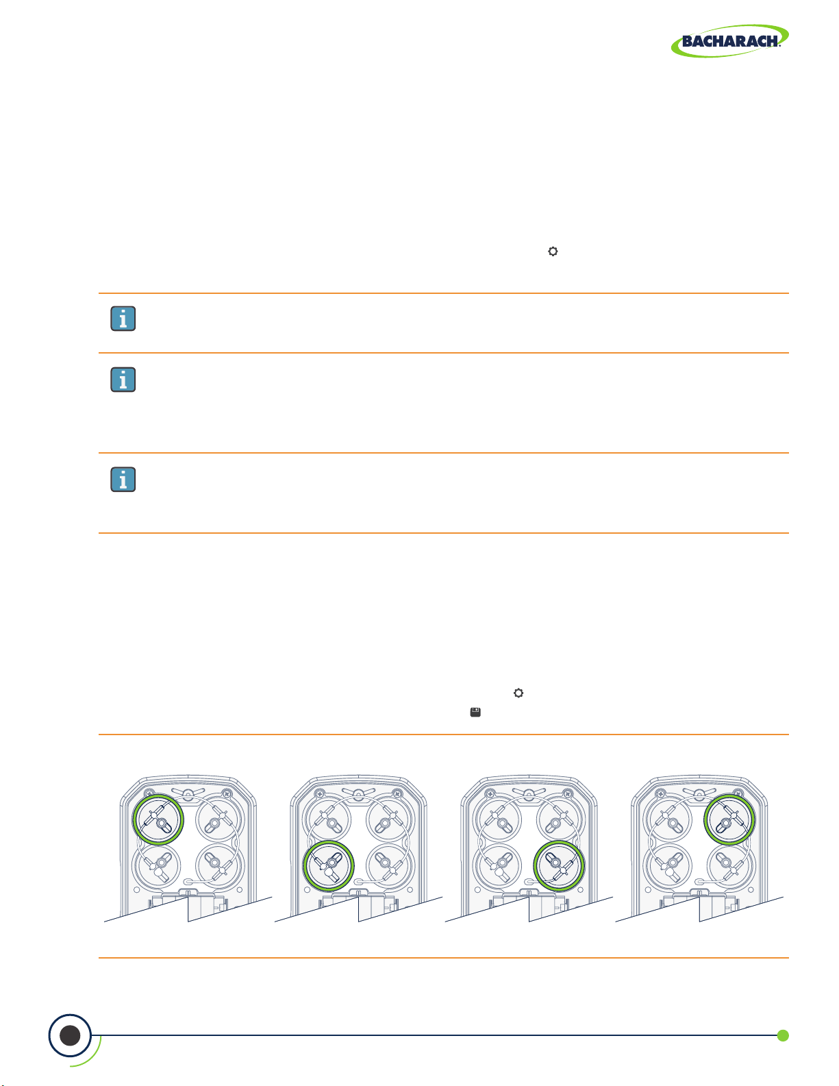
4.8 Sensor Setup
The PCA® 400 is designed to allow sensors to be interchanged in the eld; allowing users to
perform combustion tests for multiple gases with the same analyzer.
) CO Zero select Auto-Zero
Changing Sensor Setup
f To change Sensor Setup: Main Menu Settings (
sensor from dropdown menus press Save ( ).
Fig. 4-2: Gas Sensor Positions
Position 1 Position 2 Position 3 Position 4
42
) Sensor Setup select desired
0024-9551 Revision 2
Page 43

PCA® 400 User Manual
Fig. 4-3: Sensor Setup
Sensor Setup
Position 1 - the analyzer is required have an O2 sensor
in this position.
Position 1O
Position 2CO-LO
Position 2 - the analyzer can optionally have either
CO
or a CO
LOW
sensor in this position.
HIGH
Position 3 - the analyzer can optionally have None,
NO2 or a SO2 sensor in this position.
Position 3NO
Position 4NO
2
Position 4 - the analyzer can optionally have either
None or a NO sensor in this position.
Save - save changes to Sensor Setup and return to the
Settings menu.
IMPORTANT: To ensure accurate analysis results, sensors must be properly
calibrated. See Calibration (Section 5.5 and 5.6) for more information.
Establish New Oset
Restart the analyzer in fresh air after changing the sensors to establish new oset.
4.9 Bluetooth® Setup
The PCA® 400 comes standard with Bluetooth® wireless communications; allowing users to
quickly connect the instrument to an IrDA + Bluetooth® Printer.
Enabling Bluetooth
f To enable Bluetooth® communications: Main Menu Settings ( ) Bluetooth select On.
IMPORTANT: Interference can be caused by devices that are transmitting on the
same frequency band.
WARNING: Use of radio connection may not be permitted in some locations
(e.g. airplanes, hospitals). User assumes responsibility for complying with rules
governing the use of radio connections.
®
43
0024-9551 Revision 2
Page 44

PCA® 400 User Manual
4.10 Printer Setup
The PCA® 400 is capable of wirelessly transmitting data to compatible IrDA (Infrared Data
Associated) or IrDA + Bluetooth® Printers. Users can quickly change between the two
communication protocols by selecting the appropriate printer type from the analyzer’s
settings. (For more information about wireless communication ranges, see Figures 2-6 and 2-7.)
IMPORTANT: Printing via Bluetooth® is diabled when the analyzer is connected to
the PCA® 400 App. If you wish to print, disconnect from the mobile app or enable
IrDA communications.
Enabling Printing via IrDA
The analyzer can communicate data via IrDA at a distance of up to 16” (41 cm). IrDA
communication requires that the analyzer has an unobstructed view of the printer at no
more than a 30° angle.
f To enable the use of IrDA for printing: Main Menu Settings (
Enabling Printing via Bluetooth
The analyzer can communicate data via Bluetooth at a distance of up to 30’ (unobstructed).
Use of Bluetooth® will require that the communication protocol has been enabled
(Section 4.9).
f To enable the use of Bluetooth® for printing: Main Menu Settings ( ) Printer
Bluetooth select Pair (if “Status: Not Paired”) or Skip (if “Status: Paired”).
Fig. 4-4: Printer Alignment for IrDA & Sample Printout
®
) Printer select IrDA.
44
0024-9551 Revision 2
Page 45
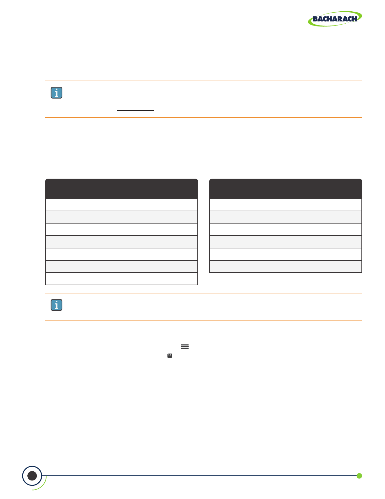
PCA® 400 User Manual
4.11 Onboard Data Logging
When the logging function is activated, up to 500 combustion test records can be
automatically stored in memory at a preset interval over a predetermined duration.
IMPORTANT: If the combination of the logging duration / interval frequency exceeds
the available memory, the analyzer will stop logging results once its memory is full.
The analyzer DOES NOT overwrite existing records.
Logged data can either be viewed on the display using the analyzer’s memory function,
or downloaded to a personal computer using the supplied PCA
Micro-B USB cable. Downloaded data is stored on the computer’s hard drive as a comma
separated value ASCII text le with a CSV extension, which can be opened by most spreadsheet
programs for analysis (see Section 6.2 for more information about the PCA
®
Reporting Software and
®
Reporting Software).
Logging Durations
5-minutes
10-minutes
15-minutes
30-minutes
1-hour
2-hours
5-hours
IMPORTANT: For more detailed information, visit www.mybacharach.com and
download the PCA® Reporting Software User Manual (P/N 0024-9552).
Turning On Data Logging
f To enable Data Logging: Options (
dropdown menu press Save ( ).
Logging Intervals
5-seconds
10-seconds
30-seconds
1-minute
5-minutes
10-minutes
) Logging enable set parameters & time via
45
0024-9551 Revision 2
Page 46
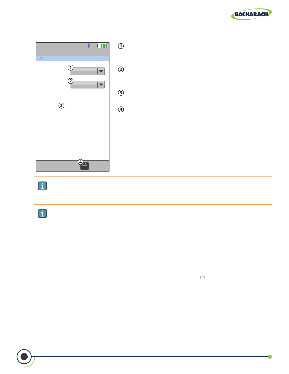
PCA® 400 User Manual
Fig. 4-5: Data Logging Settings
Logging
Metro Hospital
Duration - total duration of the combustion test
(5-minutes, 10-minutes, 15-minutes, 30-minutes, 1-hour,
2-hours and 5-hours).
Duration 5 Minutes
Interval - time elapsed in between logged results
(5-seconds, 10-seconds, 15-seconds, 1-minute, 5-minutes
Interval 5 Seconds
Available Logging
Locations
475/500
and 10 minutes).
Available Locations - remaining memory for logged
results.
Save - save changes to Data Logging Settings and
return to the Combustion Test screen.
IMPORTANT: Before turning ON data logging and starting the data logging
process, the analyzer should already be setup to perform a combustion test. See
Setup (Section 3.1) for more information.
IMPORTANT: The amount of memory available of storing new data is displayed in
the LOGGING screen (maximum of 500 locations). If previous sessions are stored and
additional memory is needed, clear the memory.
4.12 Memory File Management
The PCA® 400 allows users to save up to 500 test records to the analyzer’s internal memory.
Recalling Saved Test Data
f To recall individual test data records: Main Menu Memory (
results based on date / location.
) select desired analysis
46
0024-9551 Revision 2
Page 47
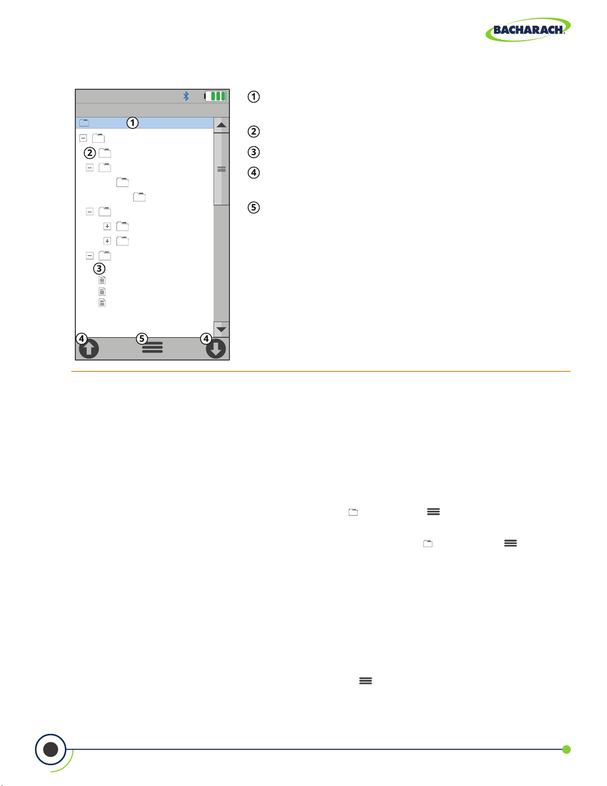
PCA® 400 User Manual
Fig. 4-6: Recalling Memory
Memory Configuration
Acme Powerplant
PCA 400
Default
Acme Powerplant
Boiler 1
Burner 1
Metro Hospital
Boiler 1
Boiler 2
USA Motorworks
10/06/17 02:50:32 PM
10/06/17 02:55:32 PM
10/06/17 03:00:32 PM
10/06/17 03:05:32 PM
Folder / Memory Location - targeted Folder / Memory
Location where data will be saved.
Directory
Saved Test Results
Navigation Arrows - scrolls to the 10 previous or next
10 les / records.
Options - displays additional settings / conguration
(Target, Edit, Add Folder, Delete All, Delete Files, Expand,
Collapse).
Navigating Memory
When viewing a directory, users can the buttons to open and close sub-directories.
Users may also use the Navigation Arrows (Figure 4-6) on the touch interface to quickly scroll
through saved records.
Clearing Memory
When all memory locations in the directory are full, they must be manually deleted in order
to store new data.
f To delete test records: Main Menu Memory (
) Options ( ) select Delete Files
conrm by selecting Yes.
f To delete folders and test records: Main Menu Memory ( ) Options ( ) select
Delete All conrm by selecting Yes.
4.13 Fresh Air Purge without Removing Probe
The PCA® 400 allows users to manually purge the analyzer with fresh air in order to keep
the electrochemical sensors from overranging.
Turning On Purge Pump
f To start the 60-second Fresh Air Purge: Options (
) Fresh Air Purge select Yes.
47
0024-9551 Revision 2
Page 48

PCA® 400 User Manual
4.14 Sensor Protection / Dilution Mode
Sensor Protection / Dilution Mode allows the instrument to dillute the gas sample in order
to protect its sensors from over-ranging during combustion analysis.
Enabling Sensor Protection
®
Sensor Protection allows the PCA
all measurements) with fresh air. A notication will alert the user that the dilution pump has
been engaged , as well as a second pump icon (
that the analyzer was diluting measurements during analysis.
400 to engage a second pump, diluting the sample (and
). Any print-outs / reports will also note
f To enable Sensor Protection / Dilution Mode: Options (
) Sensor Protection select
desired gases (CO, NO, NO2, SO2) and dillution threshold (50%, 75% or 100% of Sensor
Range) press Save ( ).
IMPORTANT: Dilution Mode will run until ALL MEASUREMENTS fall below 80% of
the set dillution threshold(s).
IMPORTANT: If not already present, the following should be installed to ensure
accurate measurement while the analyzer is in Dilution Mode:
• Gaskets (P/N: 0024-1745) in all vents in the analyzer’s component door.
• Vinyl Caps (P/N: 0005-4766) plugging vents where sensors are not present.
Fig. 4-7: Dilution Mode Notications
NGAS
Combustion Test
Acme Powerplant
Dilution Pump Status
Notication
48
Dilution Mode Enabled
0024-9551 Revision 2
Page 49

PCA® 400 User Manual
4.15 Smoke Number Test (Siegert Only)
Smoke Number (Siegert only) is used to calculate and display an average smoke value based
on 3 smoke test results that are entered by the user. Perform 3 smoke tests then enter the
results to calculate the average.
f To caluclate the Average Smoke Number: Main Menu Settings ( ) Smoke Number
use keypad to enter the numbers that most closely match the value on the smoke
scale press Save ( ).
The analyzer will display the average smoke number and include it on subsequent reports
/ printouts.
WARNING: DO NOT use the PCA 400 to sample gas from an oil-based combustion
system without first doing a smoke test and adjusting your combustion process
as needed. Smoke test results of greater than 1 indicate improper combustion,
and demonstrate the need for process adjustment. Only use the PCA 400 to
sample flue gas AFTER the combustion process is adjusted and the smoke test
indicates a smoke level of 0 or 1.
Fig. 4-8: Bacharach Oil Burner Smoke Scale
49
0024-9551 Revision 2
Page 50

PCA® 400 User Manual
4.16 Oil Derivative Test (Siegert Only)
Oil Derivative species whether or not oil derivatives were present during the smoke tests.
For incomplete combustion, oil derivatives present in the sample can be precipitated onto
the lter paper, causing a color change in the smoke spot.
f To run an Oil Derivative Test: Main Menu Settings ( ) Oil Derivative select Yes or No.
4.17 Boiler Temperature Test (Siegert Only)
A boiler temperature can be measured by an external thermocouple and recorded manually.
f To enter the Boiler Temperature: Main MenuSettings ( ) Boiler Temperature use
keypad to enter desired temperature press Save ( ).
4.18 Combustion Equations
The Combustion Equations menu allows the user to select either Siegert combustion
equations or North American combustion equations.
f To change the Combustion Equations: Menu Settings ( ) Combustion Eqns. select
Standard or Siegert (European).
IMPORTANT: Changing between Combustion Equations resets the settings and
saved test records will be deleted.
50
0024-9551 Revision 2
Page 51

PCA® 400 User Manual
5. Care & Maintenance
5.1 Emptying the Water Trap ............................................................................................... 51
5.2 Replacing the Filter Element ......................................................................................... 52
5.3 Cleaning the Probe Assembly........................................................................................ 53
5.4 Sensor Replacement ....................................................................................................... 54
5.5 B-Smart® Sensor Calibration ......................................................................................... 57
5.5.1 B-Smart® Sensors .......................................................................................................................................57
5.5.2 Starting a Calibration ................................................................................................................................58
5.5.3 B-Smart® Sensor Calibration ....................................................................................................................58
5.6 Manual Sensor Calibration ............................................................................................ 61
5.6.1 Starting a Calibration ................................................................................................................................61
5.6.2 CO
5.6.3 SO2 Sensor Calibration ..............................................................................................................................65
5.6.4 NO Sensor Calibration ...............................................................................................................................66
5.6.5 NO2 Sensor Calibration .............................................................................................................................67
5.6.6 CO
5.7 Troubleshooting .............................................................................................................. 70
5.7.1 Error Codes .................................................................................................................................................70
5.7.2 Error Symbols .............................................................................................................................................71
5.7.3 Diagnostics & Status Screens ....................................................................................................................71
Sensor Calibration ..........................................................................................................................62
LOW
Sensor Calibration ..........................................................................................................................69
HIGH
5.1 Emptying the Water Trap
The Water Trap should be emptied after every test, or as water condensate approaches the
tip of the riser tube.
1. Remove Water Trap Chamber
Pull apart the two halves of the Water Trap using a slight twisting motion to disengage the
assembly’s bayonet connection.
Fig. 5-1: Replacing the Water Trap Filter
51
0024-9551 Revision 2
Page 52

PCA® 400 User Manual
2. Pour Condensate & Reassemble Water Trap
Remove liquid condensate from the reservoir and reassemble the Water Trap by rmly
pressing the bayonet connections into place and twisting in a clockwise fashion.
IMPORTANT: When disassembling the Water Trap, care should be taken to ensure
that the o-ring does not dislodge from the Water Trap Chamber.
5.2 Replacing the Filter Element
Replace the lter element when it becomes visibly dirty or becomes saturated with water.
Materials / Equipment Required
Before cleaning the probe assembly, obtain the following items:
Water Trap Filter (P/N: 0007-1644)
Small Flat-blade Screwdriver
1. Remove Water Trap Chamber
Pull apart the two halves of the Water Trap using a slight twisting motion.
Fig. 5-2: Disassembling the Water Trap / Filter Assembly
Twist in a
counterclockwise
fashion and pull
apart.
Pry apart lter
chamber with a
small at-blade
screwdriver inserted
into notch.
52
Filter Chamber
O-Ring
Water Trap Chamber
Water Trap Filter
0024-9551 Revision 2
Page 53

PCA® 400 User Manual
2. Open Filter Chamber
Using a small at-blade screwdriver, pry apart the Filter Chamber. Remove and discard the
old Water Trap Filter.
3. Install New Filter
Install new lter and reassemble the Filter Chamber, making sure that surfaces “A” and “B”
contact each other.
4. Reassemble Water Trap Assembly
Firmly press the bayonet connections into place and twist in a clockwise fashion to secure.
5.3 Cleaning the Probe Assembly
The probe tube and sample line will become dirty during normal use.
IMPORTANT: The water trap’s lter element should prevent soot from reaching
the analyzer’s internal components. If the probe is not kept clean, it could become
clogged and restrict the ow of gas into the analyzer, resulting in incorrect
combustion test readings and calculations.
IMPORTANT: An analyzer that is used to test natural gas furnaces normally
requires less frequent cleaning than an one which is used for testing coal- or
oil-red furnaces.
Materials / Equipment Required
Before cleaning the probe assembly, obtain the following items:
Alcohol
Aerosol Can of Automotive Carburetor Cleaner
Clean Cloth
Source of Compressed Air (User Discretion)
DANGER: NEVER use ammable or combustible substances (like the carburetor uid
used to clean the probe) near an open ame.
1. Disconnect Sample Line from Water Trap
Remove the sample line from the top of the water trap.
53
0024-9551 Revision 2
Page 54

PCA® 400 User Manual
CAUTION: Carburetor cleaner will cause damage to plastic components. Take
precautions to avoid spraying cleaner onto the probe handle or analyzer.
2. Clean Sample Line with Carburetor Cleaner
Insert the plastic spray tube of the carburetor cleaner into the sample line, and liberally
spray the cleaner through the hose and out of the probe tube.
3. Flush Sample Line
After spraying, remove all of the residual cleaner by repeatedly ushing the sample line and
probe tube with alcohol.
4. Clean Exterior
Wipe the surface of the probe assembly and sample line with a clean cloth.
5. Allow to Dry
Allow the parts to dry completely. If available, blow compressed air through the sample line
and probe tube to accelerate the drying process.
6. Reconnect Sample Line to Water Trap
Pressing rmly, reconnect the sample line to the top of the water trap.
5.4 Sensor Replacement
All sensors are replaced in a similar manner. Do the following to replace either the O2,
CO
and their part numbers.
LOW
, CO
, NO, NO2, or SO2 sensor. Refer to Part Numbers (Section 7.1) for a list of sensors
HIGH
IMPORTANT: The typical life expectancies for PCA® 400 sensors are as follows
(sensor life will depend on instrument use, environmental factors and gas concentration
exposure history):
• O2 sensor has a life expectancy of 5 to 7-years,
• SO2 and NO2 sensors have life expectancies of 2-years,
• CO, CO
and NO sensors have life expectancies of 3-years.
HIGH
IMPORTANT: If not already present, the following should be installed to ensure
accurate measurement while the analyzer is in Dilution Mode:
• Gaskets (P/N: 0024-1745) in all vents in the analyzer’s component door.
• Vinyl Caps (P/N: 0005-4766) plugging vents where sensors are not present.
54
0024-9551 Revision 2
Page 55

PCA® 400 User Manual
Materials / Equipment Required
Before beginning the process of replacing sensors, obtain the following items:
Phillips-head Screwdriver
Replacement Sensor
1. Turn OFF the Analyzer
Press and hold the Power Key and allow the analyzer to complete its shutdown procedure.
2. Remove the Analyzer’s Rear Cover
Using a Phillips-head screwdriver, remove the Battery & Component Doors from the rear
of the analyzer.
Fig. 5-3: Removing Battery & Component Doors
3. Disconnect the Old Sensor
Locate the sensor which is to be replaced (sensor positions are denoted by a 1, 2, 3 or 4),
remove sample tubing and unplug the sensor assembly from the board.
55
0024-9551 Revision 2
Page 56

PCA® 400 User Manual
4. Remove Sensor Cap Assembly
While holding the base of the sensor, rmly twist the gas cup in a counterclockwise fashion
and pull straight up to remove.
5. Remove Shorting Springs from Replacement Sensor
Remove the replacement sensor from its plastic canister / packaging. Note that the CO
CO
, SO2 and NO2 sensors have a shorting spring installed between two of their pins.
HIGH
LOW
Remove and discard this spring before installing the sensor
Fig. 5-4: Discard Shorting Springs
6. Attach Sensor Cap Assembly
Attach the cap assembly to the replacement sensor by inserting the sensor into the gas
cup and twisting in a clockwise fashion.
7. Connect Replacement Sensor
Firmly press the sensor into the vacant position on the board and reconnect the sample
tubing to the gas cup.
,
IMPORTANT: When connecting the sensor assembly, it is important that the tubing
is free of crimps which could obstruct the ow of sample gases. (See Figure 5-5 for
proper sensor cap orientation.)
8. Reinstall the Analyzer’s Rear Cover
Using a Phillips-head screwdriver, return Battery & Component Doors to the rear of
the analyzer.
9. Allow Replacement Sensor to Stabilize
Allow the sensor which was just installed time to stabilize in the circuit before continuing
with this procedure. Stabilization time for all sensors (except for the NO sensor) is about
1-hour. The NO sensor baseline technically requires several days to stabilize, but should
be suciently stabilized for use in approximately 4-hours.
10. Turn ON the Analyzer
Press the Power Key and ensure that no sensor errors occur during the 60-second
warm-up.
56
0024-9551 Revision 2
Page 57

PCA® 400 User Manual
IMPORTANT: Discard old sensors in accordance with local and federal hazardous
waste disposal laws.
11.Calibrate Replacement Sensor
Enter the B-Smart
®
calibration code or manually calibrate the replacement sensor as
explained in Calibration (Sections 5.5 and 5.6). The exception to this instruction is the O
sensor which does not require calibration.
5.5 B-Smart® Sensor Calibration
IMPORTANT: Before performing any calibration procedures, ensure that the analyzer’s
batteries have sucient charge or use the optional AC power adapter. Also, ensure that
the analyzer is at room temperature and is sampling fresh air when turned ON.
2
5.5.1 B-Smart® Sensors
The PCA® 400 uses Bacharach’s B-Smart® Sensor technology for CO
and SO2. The B-Smart® Sensor is marked with a 10- or 14-digit calibration code which can
be entered via the analyzer’s interface.
Benefits of the B-Smart® Sensors include the following:
• New sensors can be installed without applying gas for calibration,
• Sensors can be pre-calibrated and installed when needed,
• Sensors can be moved from one analyzer to another and
• The analyzer’s diagnostics screen shows which sensors have been installed and their
current end-of-life condition (Good or Low).
Sensors should be calibrated by an authorized Bacharach Service Center (Section 7.2) every
6-months to 1-year to ensure that the analyzer continues to meet its published accuracy
specications. B-Smart® Sensors, however, can be calibrated in the eld if your facility has
the necessary equipment and qualied personnel to perform the procedures described in
the following sections.
LOW
, CO
, NO, NO
HIGH
2
57
0024-9551 Revision 2
Page 58

PCA® 400 User Manual
5.5.2 Starting a Calibration
Start any calibration procedure by taking the following steps:
1. Turn ON the Analyzer
Turn the analyzer ON, allowing it to cycle through its 60-second warm-up period in fresh
air. During the warm-up, the analyzer’s operation is checked and sensors are set to the
following ambient conditions:
• O
• All gas sensors are zeroed,
• The pressure sensor is zeroed.
2. Address Warm-Up Errors
Any errors detected during warm-up will be listed on the display immediately following
warm-up. Correct any errors before proceeding. Refer to Error Codes (Section 5.7.1) for a list
of error messages and their meanings.
3. Access Calibration Menu
Access the CALIBRATION MENU and use the analyzer’s touch screen or keypad to enter the
4-digit calibration password. (The calibration password can be changed and / or disabled using
the optional PCA
sensor spanned to 20.9%,
2
®
Reporting Software.)
f To access the CALIBRATION MENU: Main Menu Calibrate (
®
f PCA
400 default calibration password: 1111 press Enter ( )
5.5.3 B-Smart® Sensor Calibration
To replace / calibrate a B-Smart® sensor, do the following:
®
1. Access the B-Smart
f To access the B-Smart® Calibration Menu: Calibration Menu B-Smart
2. Scan or Manually Enter B-Smart
If your analyzer supports Near Field Communication (NFC), you may select SCAN CODE to
enter the calibration code.
f Select SCAN CODE and hold the lid from the sensor packaging near the PCA® 400 logo
on the base of the analyzer.
If you have chosen the MANUAL ENTRY method, enter the alphanumeric code supplied with
®
the B-Smart
Sensor.
f Select MANUAL ENTRY and use the analyzer’s touch screen or keypad to enter the 10- or
14-digit calibration code.
Calibration Menu
®
Calibration
)
58
0024-9551 Revision 2
Page 59

PCA® 400 User Manual
IMPORTANT: There are two B-Smart® Sensor code lengths:
• 10-digits for CO
• 14-digits for CO
IMPORTANT: If the correct code was entered, a conrmation message will display
the calibration code, the sensor type and the position of the sensor being replaced.
If an incorrect code was entered, the screen will display SENSOR: UNKNOWN.
Check to make sure the correct code has been entered. If the problem persist,
contact your nearest Bacharach Service Center (Section 7.2).
3. Turn OFF the Analyzer
Press and hold the Power Key and allow the analyzer to complete its shutdown procedure
4. Remove Cover & Locate Sensor Position
After the calibration code has been accepted, a conrmation message will display the
position of the sensor being replaced. Remove the analyzer’s rear cover and located the
sensor which is to be replaced. (Sensor positions are denoted by a 1, 2, 3 or 4.)
, NO, NO2 and SO2,
HIGH
.
LOW
Fig. 5-5: Gas Sensor Positions
Position 1 Position 2 Position 3 Position 4
5. Disconnect Sensor from Board
Take care not to bend the connector pins on the base of the sensor when removing from the
analyzer. Disconnect sample tubing from the cap assembly and pull sensor from the board.
6. Remove Cap Assembly (Gas Cup)
While holding the base of the sensor, rmly twist the cap assembly in a counterclockwise
fashion to remove. (Set the old sensor aside if it is to be returned to Bacharach for recalibration.)
59
0024-9551 Revision 2
Page 60
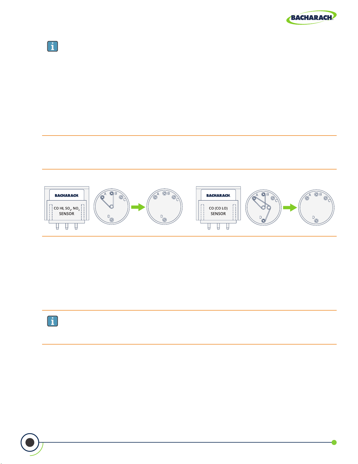
PCA® 400 User Manual
IMPORTANT: If the replacement sensor was purchased through the B-Smart®
Sensor Exchange Program, it is important that the old sensor is returned to our
factory to be recalibrated.
1. Place the old sensor in the bubble wrap and plastic container supplied with the
replacement B-Smart® sensor.
2. Seal the plastic container in the pre-paid shipping envelope and return it to Bacharach,
Inc. at the following address:
7. Remove Shorting Springs from Replacement Sensor
Remove any shorting springs which are present on the sensor pins before installation.
Fig. 5-6: Shorting Springs
ATTN: B-SMART SENSOR PROGRAM
BACHARACH, INC.
621 HUNT VALLEY CIRCLE
NEW KENNSINGTON, PA 15068-9972 USA
8. Attach Sensor Cap Assembly
Attach the cap assembly to the replacement sensor by inserting the sensor into the gas
cup and twisting in a clockwise fashion.
9. Connect Replacement Sensor
Firmly press the sensor into the vacant position on the board and reconnect the sample
tubing to the gas cup.
IMPORTANT: When connecting the sensor assembly, it is important that the tubing
is free of crimps which could obstruct the ow of sample gases. (See Figure 5-5 for
proper sensor cap orientation.)
60
0024-9551 Revision 2
Page 61

PCA® 400 User Manual
10. Reinstall the Analyzer’s Rear Cover
Using a Phillips-head screwdriver, return Battery & Component Doors to the rear of
the analyzer.
11. Allow Replacement Sensor to Stabilize
Allow the sensor which was just installed to stabilize in the circuit before continuing with
this procedure. Stabilization time for all sensors (except for the NO sensor) is about 1-hour.
The NO sensor baseline technically requires several days to stabilize, but should be
suciently stabilized for use in approximately 4-hours.
12. Turn ON the Analyzer
Turn the analyzer ON, allowing it to cycle through its 60-second warm-up period in fresh air.
5.6 Manual Sensor Calibration
5.6.1 Starting a Calibration
Start any calibration procedure by taking the following steps:
1. Turn ON the Analyzer
Turn the analyzer ON, allowing it to cycle through its 60-second warm-up period in fresh
air. During the warm-up, the analyzer’s operation is checked and sensors are set to the
following ambient conditions:
• O
sensor spanned to 20.9%,
2
• All gas sensors are zeroed,
• The pressure sensor is zeroed.
2. Address Warm-Up Errors
Any errors detected during warm-up will be listed on the display immediately following
warm-up. Correct any errors before proceeding. Refer to Error Codes (Section 5.7.1) for a list
of error messages and their meanings.
3. Access Calibration Menu
Access the CALIBRATION MENU and use the analyzer’s touch screen or keypad to enter the
4-digit calibration password. (The calibration password can be changed and / or disabled using
®
the optional PCA
f To access the CALIBRATION MENU: Main Menu Calibrate (
®
f PCA
400 default calibration password: 1111
Reporting Software.)
)
61
0024-9551 Revision 2
Page 62

PCA® 400 User Manual
5.6.2 CO
Materials / Equipment Required
Before manually calibrating the CO
Calibration Kit (P/N: 0024-7059)
Gas Cylinder (500 ppm CO in air, P/N: 0024-0492)
Gas Cylinder (1,000 ppm CO and 1,000 ppm H2 in Nitrogen, P/N: 0024-0794)
Fig. 5-7: Gas Sensor Calibration Equipment
Sensor Calibration
LOW
IMPORTANT: The CO
sensor also measures H2 for the purpose of compensating
LOW
the CO reading for the presence of H2 in the gas sample. This procedure rst spans
the CO
Leave Top
porT open
sensor and, optionally, spans the H2 part of the sensor to know gas levels.
LOW
sensor, obtain the following items:
LOW
62
Regulator*
3⁄16" I.D. Tubing*
* Part of Calibration Kit (P/N: 0024-7059)
Gas Cylinder
Gas Connector*
0024-9551 Revision 2
Page 63

PCA® 400 User Manual
1. Access the CO Calibration Menu
f To access the CO Calibration Menu: Calibration Menu CO CO + H
2
IMPORTANT: “Measured” is the current CO reading, while “Applied” refers to the
known CO level which will be applied to the sensor for calibration purposes.
CAUTION: Unless instructed by the manufacturer or an authorized service provider,
DO NOT reset sensor gain ( ) during the calibration process.
2. Apply 500 ppm CO to the Sensor
Attach a 500 ppm CO cylinder to the regulator. (For more information about the Gas Sensor
Calibration Equipment, see Figure 5-7.)
3. Adjust Flow Rate
Adjust the regulator to ensure that the flow rate is sufficient enough to calibrate the sensor.
(For more information about adjusting the ow rate, see Figure 5-8.)
Fig. 5-8: Adjusting the Flow Rate
Gas Flow Too Low
(Not enough to properly
calibrate).
Gas Flow Optimal
(Ball in ow meter is in the
“sweet spot”).
Gas Flow Too High
(Enough to calibrate but
gas is being wasted).
IMPORTANT: During the calibration process, open then adjust the knob on the
regulator to provide calibration gas to the target sensor. As you open the knob of
the regulator, the white ball inside of the ow meter will rise. Adjust the gas ow
so that the ball oats in the center of the ow meter (where the green and red hash
marks meet). This ensures sucient gas for calibration with minimal waste escaping
through the top of the ow meter.
63
0024-9551 Revision 2
Page 64

PCA® 400 User Manual
4. Enter Applied Value
Using the touch interface or keypad buttons, enter an applied value which exactly equals
the concentration stamped on the CO cylinder.
IMPORTANT: The calibration range is from 9 to 1,500 ppm. An attempt to calibrate
outside of this range will cause the message “Applied Value High” or “Applied Value Low”
appear at the bottom of the screen.
5. Allow Reading to Stabilize
Wait until the measured reading stabilizes (approximately 3 minutes), and press Save (
) to calibrate
the CO measured value to that of the applied value. The display will advance to the TEST
GAS CO / H2 screen.
6. Remove Calibration Cylinder
Turn OFF regulator and remove the 500 ppm CO cylinder.
7. Apply 1,000 ppm CO & 1,000 ppm H
Attach a combination 1,000 ppm CO and 1,000 ppm H
to the Sensor
2
cylinder to the regulator of the
2
calibration xture.
8. Enter the CO Portion of the Calibration Gas Mixture
Using the touch interface or keypad buttons, enter an applied value which exactly equals
the CO concentration stamped on the CO / H
CALIBRATE H
screen.
2
cylinder and press Save ( ) to advance to the
2
IMPORTANT: The calibration range is from 9 to 1,500 ppm. An attempt to calibrate
outside of this range will cause the message “Applied Value High” or “Applied Value Low”
appear at the bottom of the screen.
9. Enter the H
Portion of the Calibration Gas Mixture
2
Using the touch interface or keypad buttons, enter an applied value which exactly equals
the CO concentration stamped on the CO / H2 cylinder.
64
IMPORTANT: The calibration range is from 9 to 1,500 ppm. An attempt to calibrate
outside of this range will cause the message “Applied Value High” or “Applied Value Low”
appear at the bottom of the screen.
0024-9551 Revision 2
Page 65

PCA® 400 User Manual
10. Allow Reading to Stabilize
Wait until the measured reading stabilizes (approximately 3 minutes), and press Save (
the H2 measured value to that of the applied value. The message “Good Calibration” should
briefly appear followed by the CALIBRATION LIST screen.
IMPORTANT: If the sensor’s output is low, but still usable, the message “Good
Calibration WARNING Low Sensor” will appear. The sensor will now be marked as being
“Low” in the DIAGNOSTICS screen.
IMPORTANT: If the sensor’s output is too low to be usable, the message “Bad
Calibration Sensor End of Life” will appear.
11. Remove Calibration Cylinder
Turn OFF regulator and remove the 1,000 ppm CO and 1,000 ppm H
5.6.3 SO2 Sensor Calibration
Materials / Equipment Required
Before manually calibrating the SO2 sensor, obtain the following items:
Calibration Kit (P/N: 0024-7059)
Gas Cylinder (100 ppm SO2 in Nitrogen, P/N: 0024-1158)
cylinder.
2
) to calibrate
1. Access the SO
Calibration Menu
2
f To access the SO2 Calibration Menu: Calibration Menu SO2.
IMPORTANT: “Measured” is the current SO2 reading, while “Applied” refers to the
known SO2 level which will be applied to the sensor for calibration purposes.
CAUTION: Unless instructed by the manufacturer or an authorized service provider,
DO NOT reset sensor gain ( ) during the calibration process.
2. Apply 100 ppm SO
to the Sensor
2
Attach a 100 ppm SO2 cylinder to the regulator. (For more information about the Gas Sensor
Calibration Equipment, see Figure 5-7.)
3. Adjust Flow Rate
Adjust the regulator to ensure that the flow rate is sufficient enough to calibrate the sensor.
(For more information about adjusting the ow rate, see Figure 5-8.)
4. Enter Applied Value
Using the touch interface or keypad buttons, enter an applied value which exactly equals
the concentration stamped on the SO
cylinder.
2
65
0024-9551 Revision 2
Page 66

PCA® 400 User Manual
IMPORTANT: The calibration range is from 9 to 1,800 ppm. An attempt to calibrate
outside of this range will cause the message “Applied Value High” or “Applied Value Low”
appear at the bottom of the screen.
5. Allow Reading to Stabilize
Wait until the measured reading stabilizes (approximately 3 minutes), and press Save (
the SO
measured value to that of the applied value. The message “Good Calibration” should
2
briefly appear followed by the CALIBRATION LIST screen.
IMPORTANT: If the sensor’s output is low, but still usable, the message “Good
Calibration WARNING Low Sensor” will appear. The sensor will now be marked as being
“Low” in the DIAGNOSTICS screen.
IMPORTANT: If the sensor’s output is too low to be usable, the message “Bad
Calibration Sensor End of Life” will appear.
6. Remove Calibration Cylinder
Turn OFF regulator and remove the 100 ppm SO
5.6.4 NO Sensor Calibration
Materials / Equipment Required
Before manually calibrating the NO sensor, obtain the following items:
Calibration Kit (P/N: 0024-7059)
Gas Cylinder (100 ppm NO in Nitrogen, P/N: 0024-1697)
cylinder.
2
) to calibrate
1. Access the NO Calibration Menu
f To access the NO Calibration Menu: Calibration Menu NO.
IMPORTANT: “Measured” is the current NO reading, while “Applied” refers to the
known NO level which will be applied to the sensor for calibration purposes.
CAUTION: Unless instructed by the manufacturer or an authorized service provider,
DO NOT reset sensor gain ( ) during the calibration process.
2. Apply 100 ppm NO to the Sensor
Attach a 100 ppm NO cylinder to the regulator. (For more information about the Gas Sensor
Calibration Equipment, see Figure 5-7.)
66
0024-9551 Revision 2
Page 67

PCA® 400 User Manual
3. Adjust Flow Rate
Adjust the regulator to ensure that the flow rate is sufficient enough to calibrate the sensor.
(For more information about adjusting the ow rate, see Figure 5-8.)
4. Enter Applied Value
Using the touch interface or keypad buttons, enter an applied value which exactly equals
the concentration stamped on the NO cylinder.
IMPORTANT: The calibration range is from 9 to 900 ppm. An attempt to calibrate
outside of this range will cause the message “Applied Value High” or “Applied Value Low”
appear at the bottom of the screen.
5. Allow Reading to Stabilize
Wait until the measured reading stabilizes (approximately 3 minutes), and press Save (
the NO measured value to that of the applied value. The message “Good Calibration” should
briefly appear followed by the CALIBRATION LIST screen.
IMPORTANT: If the sensor’s output is low, but still usable, the message “Good
Calibration WARNING Low Sensor” will appear. The sensor will now be marked as being
“Low” in the DIAGNOSTICS screen.
IMPORTANT: If the sensor’s output is too low to be usable, the message “Bad
Calibration Sensor End of Life” will appear.
6. Remove Calibration Cylinder
Turn OFF regulator and remove the 100 ppm NO cylinder.
5.6.5 NO2 Sensor Calibration
Materials / Equipment Required
Before manually calibrating the NO
Calibration Kit (P/N: 0024-7059)
Gas Cylinder (100 ppm NO2 in Nitrogen, P/N: 0024-1157)
sensor, obtain the following items:
2
) to calibrate
1. Access the NO
f To access the NO
67
Calibration Menu
2
Calibration Menu: Calibration Menu NO2.
2
0024-9551 Revision 2
Page 68

PCA® 400 User Manual
IMPORTANT: “Measured” is the current NO2 reading, while “Applied” refers to the
known NO
CAUTION: Unless instructed by the manufacturer or an authorized service provider,
DO NOT reset sensor gain ( ) during the calibration process.
2
level which will be applied to the sensor for calibration purposes.
2. Apply 100 ppm NO
to the Sensor
2
Attach a 100 ppm NO2 cylinder to the regulator. (For more information about the Gas Sensor
Calibration Equipment, see Figure 5-7.)
3. Adjust Flow Rate
Adjust the regulator to ensure that the flow rate is sufficient enough to calibrate the sensor.
(For more information about adjusting the ow rate, see Figure 5-8.
4. Enter Applied Value
Using the touch interface or keypad buttons, enter an applied value which exactly equals
the concentration stamped on the NO
cylinder.)
2
IMPORTANT: The calibration range is from 9 to 150 ppm. An attempt to calibrate
outside of this range will cause the message “Applied Value High” or “Applied Value Low”
appear at the bottom of the screen.
5. Allow Reading to Stabilize
Wait until the measured reading stabilizes (approximately 3 minutes), and press Save (
) to calibrate
the NO2 Measured value to that of the applied value. The message “Good Calibration” should
briefly appear followed by the CALIBRATION LIST screen.
IMPORTANT: If the sensor’s output is low, but still usable, the message “Good
Calibration WARNING Low Sensor” will appear. The sensor will now be marked as being
“Low” in the DIAGNOSTICS screen.
IMPORTANT: If the sensor’s output is too low to be usable, the message “Bad
Calibration Sensor End of Life” will appear.
6. Remove Calibration Cylinder
Turn OFF regulator and remove the 100 ppm NO
68
0024-9551 Revision 2
cylinder.
2
Page 69
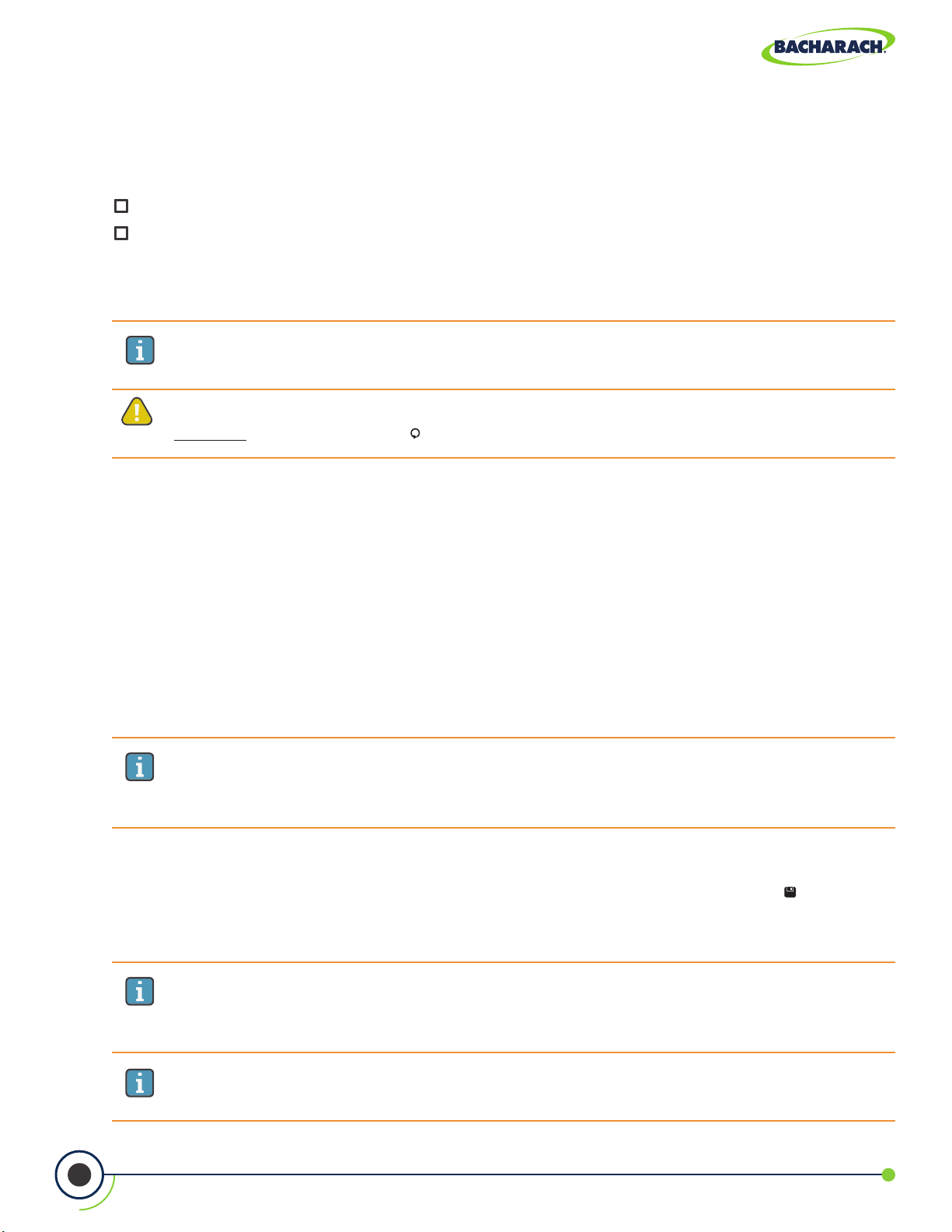
PCA® 400 User Manual
5.6.6 CO
Materials / Equipment Required
Before manually calibrating the CO
Calibration Kit (P/N: 0024-7059)
Gas Cylinder (500 ppm CO in Air, P/N: 0024-0492)
1. Access the CO Calibration Menu
f To access the CO
2. Apply 500 ppm CO to the Sensor
Attach a 500 ppm CO cylinder to the regulator. (For more information about the Gas Sensor
Calibration Equipment, see Figure 5-7.)
Sensor Calibration
HIGH
sensor, obtain the following items:
HIGH
Calibration Menu: Calibration Menu CO.
HIGH
IMPORTANT: “Measured” is the current CO reading, while “Applied” refers to the
known CO level which will be applied to the sensor for calibration purposes.
CAUTION: Unless instructed by the manufacturer or an authorized service provider,
DO NOT reset sensor gain ( ) during the calibration process.
3. Adjust Flow Rate
Adjust the regulator to ensure that the flow rate is sufficient enough to calibrate the sensor.
(For more information about adjusting the ow rate, see Figure 5-8.)
4. Enter Applied Value
Using the touch interface or keypad buttons, enter an applied value which exactly equals
the concentration stamped on the CO cylinder.
IMPORTANT: The calibration range is from 100 to 5,000 ppm. An attempt to
calibrate outside of this range will cause the message “Applied Value High” or “Applied
Value Low” appear at the bottom of the screen.
5. Allow Reading to Stabilize
Wait until the measured reading stabilizes (approximately 3 minutes), and press Save (
) to calibrate
the CO Measured value to that of the applied value. The message “Good Calibration” should
briefly appear followed by the CALIBRATION LIST screen.
IMPORTANT: If the sensor’s output is low, but still usable, the message “Good
Calibration WARNING Low Sensor” will appear. The sensor will now be marked as being
“Low” in the DIAGNOSTICS screen.
69
IMPORTANT: If the sensor’s output is too low to be usable, the message “Bad
Calibration Sensor End of Life” will appear.
0024-9551 Revision 2
Page 70

PCA® 400 User Manual
6. Remove Calibration Cylinder
Turn OFF regulator and remove the 500 ppm CO cylinder.
5.7 Troubleshooting
5.7.1 Error Codes
Message Message Type Description
T-STK Disconnected Warning
Bad Sensor Error
Low Sensor Warning
The probe thermocouple is not connected to
the analyzer’s T-Stack connector. Plug the probe
thermocouple plug into the T-Stack connector at the
bottom of the instrument.
sensor output is too low and cannot be calibrated in
O
2
the instrument and needs replaced.
O
, CO
2
low but still usable. Sensor(s) may need to be replaced
in the near future. Message will indicate which sensor(s)
are in warning.
LOW
, CO
, NO, NO2 or SO2 sensor output(s) were
HIGH
O Bias - O2 Warning
O Bias - NO Warning
Applied Value High or
Low
Warm-up Sensor Error Error
N/A
The O
period and has lost bias. The sensor will be disabled
until it has stabilized.
The NO sensor has been without power for a prolonged
period and has lost bias. The sensor will be disabled
until it has stabilized.
An attempt was made to calibrate a sensor outside its
calibration range.
• CO, CO
• Stack or Air temperature channel is measuring
• Pressure sensor is measuring pressure outside
• The instrument was turned on with the probe
sensor has been without power for a prolonged
2
, NO, NO2, or SO2 sensor(s) were not
HIGH
zeroed at warm-up because of high output. Run
instrument in fresh air then restart instrument to
re-zero sensor(s). If message persists, sensor(s) may
need to be replaced. Message will indicate which
channel(s) are in error.
temperature outside the range of -4 to 212° F
(-20 to 100° C) at startup. Make sure that the Stack
and Air Thermocouples are sampling ambient
room air within the temperature range at startup.
the range of ±3 inches of water column at startup.
Ensure that the analyzer is sampling atmospheric
pressure and restart the analyzer.
sampling ue gas. Move the probe to fresh air and
restart the analyzer.
70
0024-9551 Revision 2
Page 71

PCA® 400 User Manual
5.7.2 Error Symbols
Symbol Description
Three hyphens or dashes indicates that the calculated data cannot be displayed
---
***
XXX Indicates sensor over range.
because the measured data necessary to make the calculation is out of range. For
calculations to occur, the oxygen level must be below 16% and the stack temperature
must be below 2,000 °F (1,093 °C).
Three stars appear in the data eld of sensors that are not installed, defective, or
found to be in error during warm-up, and also in the data elds of that sensor’s
related calculated values. For example, if the data eld of either the NO or NO2
sensor contains three stars, then the NOx data eld will also contain three stars.
5.7.3 Diagnostics & Status Screens
Device Status
Displays the analyzer’s status and any errors which should be addressed (Section 5.7.1).
f To display Device Status: Main Menu Status ( ) Device Status.
Device Info
Displays the analyzer’s software version, boot version and serial number.
f To display Device Info: Main Menu Status (
) Device Info.
Main Diagnostics
Displays the analyzer’s current sensor status.
f To display Main Diagnostics: Main Menu Status (
) Main Diagnostics.
Instrument Hours
Displays total run time of the analyzer in hours of operation.
f To display Instrument Hours: Main Menu Status (
) Instrument Hours.
Pump Hours
Displays the total run time of the sample and purge pumps in hours of operation.
f To display Pump Hours: Main Menu Status (
) Pump Hours.
Memory Allocation
Displays the number of available records out of the analyzer’s limit of 500.
71
f To display Memory Allocation: Main Menu Status (
0024-9551 Revision 2
) Memory Allocation.
Page 72

PCA® 400 User Manual
Folder Allocation
Displays the number of available folders out of the analyzer’s limit of 30.
f To display Folder Allocation: Main Menu Status ( ) Folder Allocation.
Date and Time
Displays the date and time. Users can change the date and time by accessing the Settings
Menu (Section 4.2).
f To display Time and Date: Main Menu Status (
®
Bluetooth
Displays the status of the analyzer’s Bluetooth
f To display Bluetooth
Link
®
®
Link: Main Menu Status ( ) Bluetooth Link.
Battery Status
Displays the charge remaining.
f To display Battery Status: Main Menu Status (
) Time and Date.
communications.
) Battery Status.
72
0024-9551 Revision 2
Page 73

PCA® 400 User Manual
6. Additional Information
6.1 TechnicalSpecications ................................................................................................. 73
6.1.1 Instrument Details .....................................................................................................................................73
6.1.2 Approvals ....................................................................................................................................................74
6.1.3 Measurement Range & Accuracy ..............................................................................................................74
6.1.4 Calculated Readings ..................................................................................................................................75
6.2 PCA® Reporting Software ............................................................................................... 76
6.2.1 Downloaded Stored Data to a Computer ................................................................................................76
6.2.2 Importing Saved Data ................................................................................................................................76
6.3 Bacharach Combustion App .......................................................................................... 79
6.1 Technical Specications
6.1.1 Instrument Details
Specication Description / Part Number
Dimensions H
Weight
Operating Conditions
Storage Conditions
Power Supply
×W×D 10.0" × 3.8" × 2.5" (25.40 × 9.65 × 6.35 cm)
Analyzer with Battery Pack ..............................................................1.5 lb (.68 kg)
Sample Line & Probe Assembly ......................................................1.2 lb (.54 kg)
Temperature: 23° to 113° F (0° to 45° C)
Humidity: 15 to 90% RH, non-condensing
Air Pressure: 1 atmosphere ±10%
Temperature: -4° to 122° F (-20° to 50° C)
Humidity: 15 to 95% RH, non-condensing
Air Pressure: 1 atmosphere ±10%
Battery Pack: Lithium-ion Battery Pack ................................. ≈ 12-Hours*
4 × AA Batteries:
AC Adapter: 100-240VAC @ 47-63 Hz .................................. Continuous
4 × AA Disposable Lithium Batteries .............. ≈ 12-Hours*
4 × AA Disposable Alkaline Batteries .............. ≈ 5-Hours*
Display 4.3" Full-color LCD Display, Resistive Touch Interface
Wireless Communications
Sensors O
Initialization / Zeroing Time 60-seconds
* The denoted battery life is representative of normal operation using the optional screen-dimming setting.
73
IrDA: Printer(s)
Bluetooth
, CO-H2, CO
2
®
: Printer(s), Smart Device(s)
, NO, NO2, SO
HIGH
0024-9551 Revision 2
2
Page 74

PCA® 400 User Manual
6.1.2 Approvals
Approval Description
EMC tested in accordance with European Directive 2014/30/EU.
EN 50270:2015
FCC: FCC Part 15.225 and RSS 210 – Intentional Radiator
Product Approvals and
Regulatory Compliance
Electromagnetic compatibility: electrical apparatus for the detection and
measurement of combustible gases, toxic gases and oxygen.
EN50270: (CE Mark) EMC tested in accordance with European Directive
2004/108/EC.
EN50379: Standard for portable electrical apparatus designed to measure
combustion ue gas parameters of heating appliances (Siegert
only) Parts 1 and 2.
ROHS Compliance
6.1.3 Measurement Range & Accuracy
IMPORTANT: When the PCA® 400 is in Dilution Mode, the analyzer’s accuracy will be the
range stated in the following table plus an additional:
• ±1.0% O2,
• ±10% of reading for CO, CO, NO, NO
and SO2.
2
NOTE: The North American (NA) conguration of the PCA 400 computes and displays
the calculations as long as the measured oxygen is not above 16% O2 and the stack
temperature is not above 1200º C (2192º F). The Siegert conguration of the PCA 400
computes and displays the calculations as long as the measured oxygen is not above
18.8% O2 and the stack temperature is not above 1200º C (2192º F).
Measurement Range Resolution Accuracy Response Time
Ambient
Temperature
Stack
Temperature
Dierential
Temperature
Pressure /
Dierential
Pressure
-20° to 537 C
(-4° to 999° F)
-20° to 1200° C
(-4° to 2192° F)
±600° C
(±1112° F)
±179 mB
(±72 inwc)
0.1° C
(0.1° F)
1° C
(1° F)
0.1° C
(0.1° F)
0.01 mB
(0.01inwc)
±1° C (0° to 100° C) T90 < 70 seconds
±2° C (0° to 124° C)
±3° C (125° to 249° C)
±4° C (250° to 400° C)
N/A N/A
±0.03 mB (-1 to 1 mB)
±0.05 mB (-2.5 to 2.5 mB)
±3% reading (-100 to 100 mB)
T90 < 50 seconds
N/A
Flow 0 to 1 LPM 0.05 LPM ±0.1 LPM N/A
74
0024-9551 Revision 2
Page 75

PCA® 400 User Manual
Measurement Range Resolution Accuracy Response Time
O
CO-H
CO
2
2
HIGH
0 to 20.9% 0.1% ±0.3% O2 (on ue gas) T90 < 20 seconds
0 to 10,000 ppm 1 ppm
0 to 40,000 ppm 10 ppm
NO 0 to 3,000 ppm 1 ppm
NO
SO
2
2
0 to 500 ppm 1 ppm
0 to 5,000 ppm 1 ppm
6.1.4 Calculated Readings
Calculation Range Resolution
±10 ppm (0 to 200)
±5% reading (201 to 2,000)
±10% reading (2,001 to 10,000)
±10 ppm (0 to 100)
±10% reading (101 to 40,000)
±3 ppm (0 to 50)
±5% (51 to 2000)
±10% reading (> 2000)
±3 ppm (0 to 50)
±5 % (51 to 500)
±10 ppm ( 0 to 200)
±5 % reading (201 to 2,000)
±10 % reading (2,001 to 5,000)
NA (Standard) Siegert
T90 < 40 seconds
T90 < 75 seconds
T90 < 30 seconds
T90 < 40 seconds
T90 < 30 seconds
Conguration
Eciency (HHV) 0.1 to 100% 0.1%
CO
(Dry Basis) 0.1 to a fuel dependent max in % 0.1%
2
NO
x
CO Referenced to O
NO Referenced to O
NO
Referenced to O
2
NO
Referenced to O
x
SO
Referenced to O
2
2
2
2
0 to 3,500 ppm 1 ppm
0 to 9,999 ppm 1 ppm
0 to 9,999 ppm 1 ppm
0 to 9,999 ppm 1 ppm
2
0 to 9,999 ppm 1 ppm
2
0 to 9,999 ppm 1 ppm
Excess Air 1 to 250% 1%
ETA (LHV) 0 to 115% 0.1%
Stack Loss 0.1 to 100 % 0.1 %
Lambda 1 to 9.55 0.01
CO/CO2 Ratio 0.0001 to fuel-dependent max 0.0001
75
0024-9551 Revision 2
Page 76

PCA® 400 User Manual
6.2 PCA® Reporting Software
A PC with PCA® Reporting Software (PRS) installed can set, edit and transfer the following data:
• Live Data Reporting
• Time and Date
• Custom Fuels
• Test ID
6.2.1 Downloading Stored Data to a Computer
The combustion test data which was stored in either the analyzer’s Memory Directory
can be downloaded to a computer using the PRS and USB cable that are supplied with
the analyzer.
The downloaded data is stored on the computer’s hard drive – or removable media of the
operator’s choosing – as a comma-separated-value ASCII text le with a CSV extension. This
type of le can be opened by most spreadsheet applications for analysis.
For more information about the installation of the PRS, refer to the operation manual
(P/N: 0024-9552) which can be downloaded from Bacharach’s website, www.mybacharach.com.
• Username
• Logo / Graphic
• Instrument Setup
• Calibration Password
• B-Smart
• Test Records
• Firmware Updates
®
Code
Minimum Computer Requirements for PCA
Category Minimum Requirement
Operating System Windows 7, 8, 10
Access Port USB port (USB 1.1, 2.0, or 3.0)
Software: 205mb for the PCA® Reporting Software
Hard Drive Space
Data: 350
6.2.2 Importing Saved Data
Data which has been recovered and saved as an ASCII text le with a CSV extension, as
described above, can be opened in most spreadsheet applications (Microsoft Excel, Google
Sheets, etc.). If the application does not recognize the CSV le extension, then refer to the
spreadsheet’s documentation for information on how to manually import comma-delimited
text les.
®
Reporting Software
kb for each downloaded le
76
0024-9551 Revision 2
Page 77

PCA® 400 User Manual
The table below contains listings and descriptions of the 32 data elds that are downloaded
with each data record. Note that for sensors that are not installed, all related data elds for
those sensors will be marked as “***”. For example, if the analyzer does not contain an SO
sensor, then “***” will appear in NA data elds 22 and 23.
Downloaded Data Fields
2
Field
NA S
Column Name Data Name or Value
1 1 Date Date of Test (MM/DD/YY)
2 2 Time Time of Test (12-Hour Format)
3 3 Folder Information Input by User
4 4 Subfolder Information Input by User
5 5 Fuel Fuel Name
6 6 % O
2
Oxygen Level
7 7 CO Carbon Monoxide Level
8 8 ppm CO (O2) Carbon Monoxide Reference to a % of O
9 13 % Eciency Combustion Eciency
10 10 % CO
2
Carbon Dioxide Level
11 % EA Excess Air
12 14 TStk Stack Temperature
13 15 TAir Primary / Ambient Air Temperature
14 16 Delta-T Dierential Temperature Value
15 17 Temp Units Temperature Units
2
16 18 NO Nitric Oxide Level
17 19 ppm NO (O2) Nitric Oxide Level Referenced to a % of O2
18 20 NO
2
Nitric Dioxide Level
19 21 ppm NO2 (O2) Nitric Dioxide Level Referenced to a % of O2
20 22 NO
21 23 ppm NO
22 24 SO
x
(O2) Nitrogen Oxide Level as Referenced to a % of O2
x
2
NO + NO2
Sulfur Dioxide
23 25 ppm SO2 (O2) Sulfur Dioxide Level Referenced to a % of O
24 26 CO_O2Ref % O2 Reference for CO
25 27 NOx_O2Ref % O2 Reference for NOx
26 28 SO2_O2Ref % O2 Reference for SO
27 29 Pollution Units Pollution Units of Measure
2
(1)
28 30 Flow Instrument sample pump ow rate
29 42 Dilution Dilution Mode Active
(1)
Pollution units as selected (Section 3.2.1).
2
77
0024-9551 Revision 2
Page 78

PCA® 400 User Manual
Field
NA S
Column Name Data Name or Value
30 43 Pressure Pressure (Draft) Valve
31 44 Pressure Units Pressure Units of Measure
(2)
32 45 Avg Duration Combustion average test duration
33 46 Avg Interval Combustion average test interval
34 CO/CO
35 CO
Max(%) Setting for maximum Carbon Dioxide in stack gases
2
2
Ratio of Carbon Monoxide to Carbon Dioxide
36 Start Pressure Initial leak test pressure
37 End Pressure Final leak test pressure
38 Change Pressure Calculated dierence between initial and nal leak test pressures
39 Test Time Time elapsed during leak test
40 Test Time Units Minutes or seconds
41 Leak Type Test Let-By Test or Tightness Test
11 %ETA Eciency using lower heating value
12 %qA Stack loss using on lower heating values
9 Lambda Excess Air
31 Avg Smoke The average smoke value of three smoke test results
32 Oil Derive Species whether oil derivatives were present in smoke tests
33 Boiler Temp Temperature measured by external thermocouple
(2)
Pressure units as selected (Section 3.3.1).
78
0024-9551 Revision 2
Page 79

PCA® 400 User Manual
6.3 Bacharach Combustion App
To download the Bacharach Combustion App, visit www.mybacharach.com/apps. The
companion smartphone application allows users to perform a variety of functions without
needing to be in front of their analyzer:
• Control the PCA® 400 (start and stop the analyzer via Bluetooth®)
• View real-time measurements
• Generate customizable reports (reports may be shared via available email / cloud services)
®
Minimum Computer Requirements for PCA
Category Minimum Requirement
Reporting Software
Operating System
Communications Bluetooth
Hard Drive Space
Android 5.0 and later
iOS 10 and later
Android: 50mb (for the application only)
iOS: 30
®
4.0 or later (not compatible with Bluetooth® 3.0 or Bluetooth® Classic)
mb (for the application only)
79
0024-9551 Revision 2
Page 80

PCA® 400 User Manual
7. Parts & Accessories
7.1 Part Numbers .................................................................................................................. 80
7.2 Service Center Locations ............................................................................................... 82
7.1 Part Numbers
Product Description / Part Number
Accessories
Description:
Active Sample Conditioner Kit
The Active Sample Conditioner extracts
water vapor from samples, allowing the
PCA® 400 to accurately read levels of
NOx or SO2.
®
IrDA + Bluetooth
Printer Paper (contains 5 rolls of paper)
®
Tru Spot
PCA
Flue Plugs, 5/16" (contains 50 metal plugs)
Sample Line & Probe Assembly
Probe, 12"
Probe, 24"
Smoke Tester
®
400 Carrying Case P/N: 0024-0865
Printer
P/N: 0024-8558
The IrDA + Bluetooth® Printer allows
Description:
P/N: 0024-1680
P/N: 0024-1310
Description:
P/N: 0021-7006
P/N: 0024-8557
P/N: 0024-3231
P/N: 0024-3232
technicians to print reports directly
from their analyzer without a wired
connection.
The True Spot® Smoke Tester helps
technicians quickly check smoke levels
in ue gases.
Probe, 36"
80
P/N: 0024-3233
0024-9551 Revision 2
Page 81
PCA® 400 User Manual
Product Description / Part Number
Sample Line & Probe Assembly (continued)
Buna-N Sample Line Assembly with Water Trap, 7.5'
Buna-N tubing is recommended for
Description:
applications which do not require
accurate NO2 or SO2 measurement.
P/N: 0024-3234
Buna-N Sample Line Assembly with Water Trap, 15'
P/N: 0024-3235
Viton® tubing is recommended for
Viton
®
Sample Line Assembly with Water Trap, 7.5'
Description:
applications which require accurate NO2
or SO2 measurement.
P/N: 0024-3236
®
Viton
Sample Line Assembly with Water Trap, 15' P/N: 0024-3237
Sensors
O
Sensor P/N: 0024-1652
2
CO Sensor (B-Smart
CO Sensor (Not Calibrated)
CO
Sensor (B-Smart® Pre-calibrated Sensor) P/N: 0024-1542
HIGH
CO
Sensor (Not Calibrated) P/N: 0024-0997
HIGH
SO
Sensor (B-Smart® Pre-calibrated Sensor) P/N: 0024-1543
2
SO
Sensor (Not Calibrated) P/N: 0024-0998
2
NO
Sensor (B-Smart® Pre-calibrated Sensor) P/N: 0024-1544
2
®
Pre-calibrated Sensor) P/N: 0024-1687
P/N: 0024-1660
NO
Sensor (Not Calibrated) P/N: 0024-1027
2
NO Sensor (B-Smart
®
Pre-calibrated Sensor) P/N: 0024-1691
NO Sensor (Not Calibrated)
Filters / Gaskets / Caps
Water Trap Kit
Water Trap Filters (contains 3 lters)
Gasket
Vinyl Cap
81
P/N: 0024-0881
P/N: 0019-3265
P/N: 0007-1644
P/N: 0024-1745
P/N: 0005-4766
0024-9551 Revision 2
Page 82

PCA® 400 User Manual
Product Description / Part Number
Calibration Gases
500 ppm CO in Air
1000 ppm CO/H
in Nitrogen Balance P/N: 0024-0794
2
100 ppm NO in Nitrogen Balance
100 ppm NO
100 ppm SO
in Nitrogen Balance P/N: 0024-1157
2
in Nitrogen Balance P/N: 0024-1158
2
Calibration Kit
P/N: 0024-0492
P/N: 0024-1697
P/N: 0024-7059
Power Supply
NO Bias Battery
Lithium-Ion Battery Pack
USB Communications / Power Cable
Universal AC Power Adapter
P/N: 0204-0020
P/N: 0024-1664
P/N: 0104-4034
P/N: 0024-1681
7.2 Service Center Locations
Prior to shipping equipment to Bacharach, visit www.mybacharach.com/service for
an Returned Merchandise Authorization Number (RMA #). All returned goods must
be accompanied with an RMA #. Pack the equipment securely (in its original packing,
if possible), as Bacharach cannot be held responsible for any damage incurred during
shipping to our facility.
82
Location Contact Information Shipping Address
Bacharach, Inc.
621 Hunt Valley Circle
ATTN: Service Department
Bacharach, Inc.
114A Georges Street Lower
ATTN: Service Department
Bacharach, Inc.
10 West Pearce Street, Unit 4
ATTN: Service Department
United States
Europe
Canada
Phone: +1 724 334 5000
Toll Free: +1 800 736 4666
Fax: +1 724 334 5001
Email: help@mybacharach.com
Phone: +353 1 284 6388
Fax: +353 1 284 6389
Email: help@mybacharach.com
Phone: +1 905 882 8985
Fax: +1 905 882 8963
Email: support@bachcan.ca
0024-9551 Revision 2
New Kensington, PA 15068, USA
Dun Laoghaire, Dublin, Ireland
Richmond Hill, Ontario L4B 1B6, Canada
Page 83

Bacharach, Inc.
621 Hunt Valley Circle,
New Kensington, PA 15068 USA
Pittsburgh, PA USA | Dublin, IRE | Gloucester, UK | Stanardsville, VA USA | Toronto, CAN
www.mybacharach.com | help@mybacharach.com
 Loading...