

Page 1

INSTRUCTION 0023-9125
ODOROMETER
Portable Gas Odorant Tester
Part Number 5110-0200
Operation/Maintenance
Rev. 16 – May 2010
WARNING!
Because this instrument is used to detect and monitor materials and
conditions which are listed by OSHA or others as potentially hazardous
to personnel and property, the information in this manual must be fully
understood and utilized to ensure that the instrument is operating properly and is both used and maintained in the proper manner by qualifi ed
personnel. An instrument that is not properly calibrated, operated and
maintained by qualifi ed personnel is likely to provide erroneous infor-
mation, which could prevent user awareness of a potentially hazardous
situation for the instrument user, other personnel and property.
If, after reading the information in this manual, the user has questions
regarding the operation, application or maintenance of the instrument,
supervisory or training assistance should be obtained before use. Factory
assistance is available by calling 724-334-5000.
Ph: 724-334-5000 • Fax: 724-334-5001 • Toll Free: 800-736-4666
Website: www.mybacharach.com • E-mail: help@mybacharach.com
Printed in U.S.A. ®Registered Trademark
621 Hunt Valley Circle, New Kensington, PA 15068
World Headquarters
Page 2

WARRANTY
BACHARACH, Inc., warrants to Buyer that at the time of delivery this Product will be free from defects in
material and manufacture and will conform substantially to BACHARACH Inc.’s applicable specifi cations.
BACHARACH’s liability and Buyer’s remedy under this warranty are limited to the repair or replacement, at
BACHARACH’s option, of this Product or parts thereof returned to Seller at the factory of manufacture and
shown to BACHARACH Inc.’s reasonable satisfaction to have been defective; provided that written notice of the
defect shall have been given by Buyer to BACHARACH Inc. within one (1) year after the date of Delivery of this
product by BACHARACH, Inc.
BACHARACH, Inc. warrants to Buyer that it will convey good title to this Product. Bacharach’s liability and Buyer’s
remedy under this warranty of title are limited to the removal of any title defects or, at the election of Bacharach,
to the replacement of this Product or parts thereof that are defective in title.
The warranty set forth in paragraph 1 does not apply to parts the Operating Instructions designate as having a
limited shelf-life or as being expended in normal use.
THE FOREGOING WARRANTIES ARE EXCLUSIVE AND ARE GIVEN AND ACCEPTED IN LIEU OF (i)
ANY AND ALL OTHER WARRANTIES, EXPRESS OR IMPLIED, INCLUDING WITHOUT LIMITATION THE
IMPLIED WARRANTIES OF MERCHANTABILITY AND FITNESS FOR A PARTICULAR PURPOSE: AND (ii)
ANY OBLIGATION, LIABILITY, RIGHT, CLAIM OR REMEDY IN CONTRACT OR TORT, WHETHER OR NOT
ARISING FROM BACHARACH S NEGLIGENCE, ACTUAL OR IMPLIED. The remedies of the Buyer shall be
limited to those provided herein to the exclusion of any and all other remedies including, without limitation incidental or consequential damages. No agreement varying or extending the foregoing warranties, remedies or this
limitation will be binding upon Bacharach, Inc. unless in writing, signed by a duly authorized offi cer of Bacharach.
Batteries, being expendable items, are excluded from the terms of this warranty.
A
Page 3

ODOROMETER
OPERATING AND MAINTENANCE INSTRUCTIONS
For The
ODOROMETER
1. APPLICATION
2. DESCRIPTION
The ODOROMETER is a portable instrument that can be used by gas
companies to check the odorization of the gas being distributed. The instrument provides an easy method of determining the odor intensity of a
gas stream at any convenient point in the gas distribution or transmission
lines, and is a faster method of determining odor levels at high or low
gas-air concentrations than the room-test method. The range of testing
on the standard instrument is from one-twentieth of 1% to slightly over
l% gas in air. This range enables the operator to check the accepted gas
concentrations for the detection of an odorant in natural gas.
The ODOROMETER may also be used to perform natural gas odor intensity tests in accordance with ASTM D 6273-98. (ASTM is the American
Society for Testing and Materials.)
The ODOROMETER uses a constant-speed motor-driven blower to produce a constant fl ow of air, which is discharged from a glass SNIFFING
FUNNEL through an opening in the top of the case, where the operator
can sniff it conveniently for the presence of detectable odor. The gas to be
tested is supplied to the instrument under its own pressure and metered
by a FLOWMETER (also known as a Rotameter) and needle valve. The
concentration of gas in the effl uent air is determined from the FLOWMETER
reading by reference to the calibration chart on the inside of the front cover.
The instrument components are mounted on an anodized aluminum panel
which, in turn, mounts inside an anodized aluminum case. All metal and
instrument surfaces have been chosen so that no outgas problems will
occur. Make sure not to use any chemicals on the instrument that would
give off residual odors.
Instruction 0023-9125 Page-3
The ODOROMETER is a DC model completely independent of the power
line and takes power from a battery pack consisting of fi ve size-D Alka-
line cells. This model is adjusted at the factory for proper blower speed
and contains a front panel POWER LED which indicates that the unit is
working properly.
NOTE: Two older versions of the ODOROMETER, an AC and
DC model are still in use, and supported by Bacharach Inc.
The AC model uses a shaded-pole constant-speed motor to drive
the blower, and the instrument is equipped with a line cord for
convenient connection to any 115 volt 60 cycle power source.
The blower speed of the DC model is controlled by a rheostat
and is set using the reading of the built-in milliammeter.
Because there are slight differences in the three models, the older models will be referred to in Appendix A, which only needs to
be referenced when using one of these older models.
Page 4
ODOROMETER
ON
10
8
6
4
2
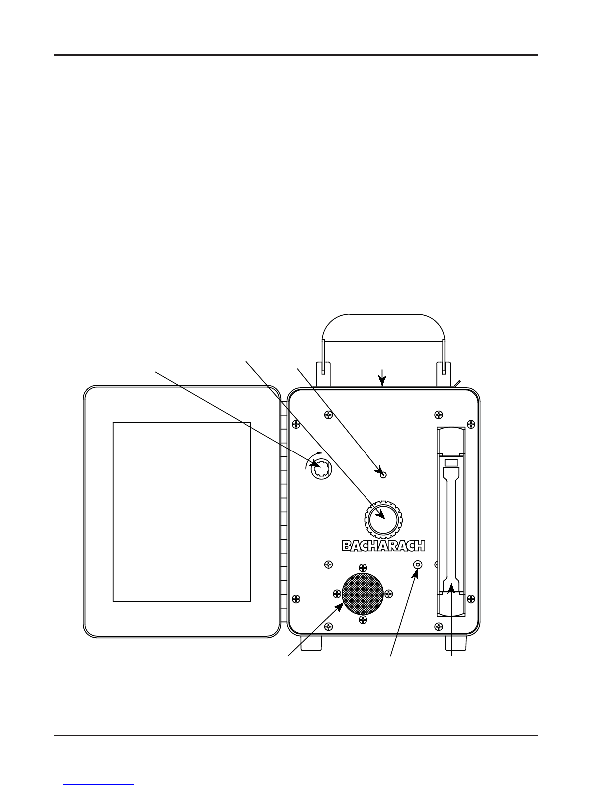
ODOROMETER
ON - OFF
SWITCH
POWER
LED
GAS INLET
NEEDLE
VALVE
SNIFFING
FUNNEL
FLOWMETER
GAS
INLET
FITTING
AIR
INLET
3. OPERATING
INSTRUCTIONS
1. Make sure batteries are in place (See Appendix A-1 for AC models).
2. The gas supply should be connected to the inlet fi tting on the front
3. Where possible, tests should be run in an odor and draft free area.
4. Set the instrument on a level bench or desk. Swing the handle down,
NOTE: If the LED goes out after a few seconds, replace the batteries.
5. The GAS INLET NEEDLE VALVE is located in the center of the
panel, and pressure should be below 5 psig. Connection should be
made with aluminum or plastic tubing only; do not use copper or
rubber, as these tend to remove odorant compounds. A 6 foot length
of suitable plastic tubing is supplied with the instrument.
and the top cover open. Switch the unit "ON" (Clockwise), the green
POWER LED should light (See Appendix A-2 for older models).
panel. Open the valve slowly while sniffi ng the air being discharged
from the SNIFFER FUNNEL opening in the top of case.
ODOROMETER
Page-4 Instruction 0023-9125
Page 5

ODOROMETER
6. The observer must be careful to hold his nose within one inch of the
SNIFFING FUNNEL to avoid dilution with the surrounding air
(placing the upper lip on the handle will allow the nose to be centered about one inch above the SNIFFING FUNNEL).
7. Odor level rating must be based on the fi rst sniff or two because the
olfactory senses fatigue rapidly with continued exposure to an odor.
8. Between sniffs the observer should breathe deeply but slowly
through his nose to “regenerate” his perception.
4. THRESHOLD
ODOR
DETERMINATION
1. Have the observers sniff the unodorized air stream.
2. Adjust the gas fl ow rate to the estimated threshold value and let the
observers sniff again to see if they can smell any foreign odor.
3. Adjust the gas concentration upward or downward, as indicated by
the above test, and have the observers sniff again.
4. Repeat this procedure until the threshold value is obtained for each
observer. It is best to take several readings on both sides of the
threshold and to run an occasional blank using air with no added
gas.
5. Calculate the average threshold value of each observer. Then
calculate the total average value, using these individual averages.
This procedure is advisable because considerable variation is found
among individuals in detecting threshold value. Thus, if the observers take different numbers of readings, a “straight” average of all
these values would give more weight to the observer with the larger
number of readings.
6. It is essential for this type of determination that the odor level rating be based on the fi rst sniff only, because fatigue is very rapid in
this range.
5. ODOR
CHARACTERISTICS
AT STANDARD
CONCENTRATION
Instruction 0023-9125 Page-5
1. Have the observers sniff the unodorized air stream.
2. Adjust the gas rate to the desired concentration.
3. Have the observers sniff the effl uent air stream, rating the odor in-
tensity as (1) absent, (2) barely detectable, (3) readily detectable, (4)
strong, (5) very strong (obnoxious).
4. If desired, a description of the character of the odor, such as onion,
garbage, refi nery, etc., can also be obtained.
5. Repeat the test after a short time to check the fi rst determination.
Page 6

ODOROMETER
6. RANGE OF
MEASUREMENT
7. MAINTENANCE
8. HOW TO USE THE
ODOROMETER GAS
CALIBRATION
CHART
The instrument has two ranges, obtained by using a lightweight glass
and a heavier metal fl oat, both in the same metering tube. Take readings
on the glass fl oat when both are within the range of measurement; take
readings on the metal fl oat when the glass fl oat reaches the top of the tube.
Useful ranges are approximately 0.04 to 0.4% for the glass fl oat, and 0.2
to 1.1% for the metal fl oat.
When taking readings, observe the FLOWMETER graduation corresponding
to the bottom of the ball fl oat. Find the gas concentration corresponding to
this reading by looking at the calibration chart on the inside of the front
cover. This chart has been drawn to give the percent gas concentration over
the useful ranges for natural gas with a specifi c gravity of 0.620 relative
to air. Concentrations of gases of other densities may be read using the
correction factors shown on the graph below the calibration chart.
FLOWMETER tube and fl oats must be kept clean to prevent
The
sticking of the fl oats in the tube. To disassemble, press the sides of the
plastic cover and pull out. Remove the spring lock clip at the top of tube,
lift the tube connector and pull tube out, by lifting from the bottom connectors. Tube and fl oats can be washed in alcohol, trichloroethylene or
other solvent.
When the odor (mercaptan) in gas has been detected, observe the reading
indicated by the FLOWMETER fl oat. Depending on the range required,
use either the upper glass fl oat (colored) for values 0.04 to 0.4% or lower
metal fl oat (silver) for values 0.2 to 1.2%.
EXAMPLE: FLOWMETER (silver fl oat) indicates 7; use second curve and
observe that percent gas indicated by the chart is 1.1% (%
GAS IN ODOROMETER EFFLUENT). If specifi c gravity of
gas under test is 0.620, the correct percentage of gas is as
noted on the curve (1.1%). If specifi c gravity differs, use the
CORRECTION CHART below.
EXAMPLE: Specifi c gravity of gas under test is 0.55, the correction factor
noted on the chart is 1.06. The correct gas concentration is
obtained by multiplying the following:
1.1% x 1.06 = 1.166% (Gas in ODOROMETER Effl uent).
Page-6 Instruction 0023-9125
Page 7

ODOROMETER
Instruction 0023-9125 Page-7
ODOROMETER GAS CALIBRATION CHART
This chart is intended as an example only and does not refl ect the cali-
bration of your instrument. See actual calibration graph on your instrument.
Your ODOROMETER was calibrated against standards traceable to
Page 8

ODOROMETER
9. SERVICE
the National Institute of Standards and Technology (NIST) prior to its
shipment from the factory. To ensure the instrufment’s continued accuracy and reliability, Bacharach recommends periodic calibration by an
authorized Bacharach Service Facility. For best results, the instrument
should be initially calibrated after no longer than one year of service.
Thereafter, the calibration interval should be set as needed to ensure
continued reliability. If calibrated by a Bacharach Service Facility,
the assigned interval will be based upon the instrument’s condition as
received, in or out-of-tolerance and degree of drift since the last calibration.
Bacharach recommends that service on portable instruments, in or out
of warranty, be performed at one of our Service Centers. Should service
be required, please pack the instrument carefully, include all necessary
identifying papers (with description of service needed), and ship prepaid
to one of the below:
United States
Bacharach Sales/Service Center
621 Hunt Valley Circle
New Kensington, PA 15068
Phone: 724-334-5051
Fax: 724-334-5723
Email: help@bacharach-inc.com
Canada
Bacharach of Canada, Inc.
20 Amber St. Unit #7
Markham, Ontario L3R SP4 Canada
Phone: 905-470-8985
FAX: 905-470-8963
E-mail: bachcan@idirect.com
Page-8 Instruction 0023-9125
Page 9

ODOROMETER
APPENDIX A
OLDER VERSIONS OF THE ODOROMETER
1. Instruments designed to operate from AC will operate from any 115
volt, 60 Hz power source.
2. For the DC model, start motor by turning switch clockwise to “ON”
and rotating the knob clockwise until air fl ow is achieved. Set am-
meter to red mark for proper amount of air fl ow. For the AC model,
just plug in line cord and turn on switch to start air fl ow. Pilot light
will indicate that power is connected to motor.
Instruction 0023-9125 Page-9
 Loading...