

Page 1

1100-2294 Rev 1 1
Page 2

1100-2294 Rev 1 1
WARRANTY POLICY
Bacharach, Inc. warrants to buyer that at the time of delivery this product will be free from defects in material and manufacture and
will conform substantially to Bacharach, Inc.’s applicable specifications. Bacharach’s liability and buyer’s remedy under this warranty
are limited to the repair or replacement, at Bacharach’s option, of this product or parts thereof returned to seller at the factory of
manufacture and shown to Bacharach, Inc.’s reasonable satisfaction to have been defective; provided that written notice of the
defect shall have been given by buyer to Bacharach, Inc. within one (1) year after the date of delivery of this product by Bacharach,
Inc.
Bacharach, Inc. warrants to buyer that it will convey good title to this product. Bacharach’s liability and buyer’s remedy under this
warranty of title are limited to the removal of any title defects or, at the election of Bacharach, to the replacement of this product or
parts thereof that are defective in title.
THE FOREGOING WARRANTIES ARE EXCLUSIVE AND ARE GIVEN AND ACCEPTED IN LIEU OF (I) ANY AND ALL OTHER
WARRANTIES, EXPRESS OR IMPLIED, INCLUDING WITHOUT LIMITATION THE IMPLIED WARRANTIES OF
MERCHANTABILITY AND FITNESS FOR A PARTICULAR PURPOSE: AND (II) ANY OBLIGATION, LIABILITY, RIGHT, CLAIM OR
REMEDY IN CONTRACT OR TORT, WHETHER OR NOT ARISING FROM BACHARACH’S NEGLIGENCE, ACTUAL OR
IMPLIED. The remedies of the buyer shall be limited to those provided herein to the exclusion of any and all other remedies
including, without limitation incidental or consequential damages. No agreement varying or extending the foregoing warranties,
remedies or this limitation will be binding upon Bacharach, Inc. unless in writing,
signed by a duly authorized officer of Bacharach.
Register Your Warranty by Visiting: www.mybacharach.com/warranty-registration/
SERVICE POLICY
Bacharach, Inc. maintains a service facility at the factory. Some Bacharach distributors / agents may also have repair facilities;
however, Bacharach assumes no liability for service performed by anyone other than Bacharach personnel. Repairs are warranted
for 90-days after date of shipment (sensors, pumps, filters and batteries have individual warranties). Should your analyzer require
non-warranty repair, you may contact the distributor from whom it was purchased or you may contact Bacharach directly.
If Bacharach is to do the repair work, send the monitor, prepaid, to the closest service center. Prior to shipping equipment to
Bacharach, visit www.mybacharach.com for a Returned Merchandise Authorization Number (RMA #). All returned goods must be
accompanied by a RMA #. Pack the equipment securely (in its original packing, if possible), as Bacharach cannot be held
responsible for any damage incurred during shipping to our facility. Always include your RMA #, shipping address, telephone
number, contact name, billing information and a description of the defect as you perceive it. You will be contacted with a cost
estimate for expected repairs prior to the performance of any service work. For liability reasons, Bacharach has a policy of
performing all needed repairs to restore the monitor to full operating condition.
NOTICES
Product improvements and enhancements are on-going, therefore the specifications and information contained in this document
may change without notice.
Bacharach, Inc. shall not be liable for errors contained herein or for incidental or consequential damages in connection with the
furnishing, performance, or use of this material.
No part of this document may be photocopied, reproduced, or translated to another language without the prior written consent of
Bacharach, Inc.
Copyright © 2019, Bacharach, Inc., All Rights Reserved.
BACHARACH is a registered trademark of Bacharach, Inc. All other trademarks, trade names, service marks and logos referenced
herein belong to their respective companies.
Page 3

1100-2294 Rev 1 2
Table of Contents
Table of Contents 2
1. Introduction 6
1.1 About this Manual 6
1.2 Conventions 6
1.2.1 Short Form Instructions 6
1.2.2 Iconography 6
1.3 General Safety Statements 7
1.4 Safe Connection of Electrical Devices 8
2. Product Descriptions 9
2.1 Intended Uses / Applications 9
2.2 Transmitter Construction 9
2.3 Power Options 9
2.4 Diagnostic / Status LED 10
2.5 Configurable Output Signals 10
2.6 User Interface 10
2.7 Technical Specifications 10
2.8 Components 13
2.8.1 MGS-410 Components 13
2.8.2 MGS-450 Components 14
2.8.3 MGS-460 Components 15
3. Installation 16
3.1 General Information 16
3.2 Restrictions 17
3.3 Mechanical Installation 17
3.4 Electrical Installation 17
3.4.1 Preparations 17
3.4.2 Power & Signal Wiring 18
3.4.3 Relay Wiring 19
3.4.4 Installation of Remote Sensing Head 19
3.4.5 Connecting to MGS-408 Gas Detection Controller 20
3.4.6 Modbus RTU RS-485 Interface 20
Page 4

1100-2294 Rev 1 3
3.4.7 Confirming Instrument Functionality 21
4. Operation 22
4.1 Overview of Normal Operation 22
4.1.1 Applying Power & the Start-up Sequence 22
4.1.2 Verifying Analog Signals 22
4.1.3 Verifying the Modbus Signal 23
4.1.4 Status Indication 24
4.1.5 Switch Functions 24
4.1.6 Reset System to Factory Default Settings 25
4.2 MGS-400 Smartphone Application 26
4.2.1 Enable Bluetooth® Connection 26
4.2.2 Checking Status 26
4.2.3 Instrument Configuration 28
4.2.3.1 Change Alias 28
4.2.3.2 Change Unlock Code 28
4.2.3.3 Change Bluetooth Passcode 28
4.2.3.4 Reset to factory defaults 29
4.2.3.5 Alarm Configuration 29
Low Alarm Setpoint 29
High alarm Setpoint 30
Alarm Latching 30
4.2.3.6 Modbus Configuration 30
Address 30
Baud Rate 31
Stop Bits 31
Parity 31
Enable 120Ω Termination 31
4.2.3.7 Output Configuration 31
Analog Output Range 31
Buzzer 32
Relay Failsafe 32
Alarm Delay 32
Analog Zero Adjust 32
Page 5

1100-2294 Rev 1 4
Analog Span Range 33
5. Care & Maintenance 34
5.1 Maintenance Intervals 34
5.2 Adjustments 35
5.2.1 Introduction 35
5.2.2 General Calibration Procedure 36
5.2.3 Zero Adjustment 36
5.2.4 Span Adjustment 37
5.2.5 System Bump Test 38
5.3 Troubleshooting 39
5.3.1 Hexadecimal Format 39
5.3.3 Fault Codes 39
5.4 Sensor Maintenance 41
5.4.1 Replacing the Sensor Module 41
5.5 Cleaning the Instrument 42
6. Additional Information 43
6.1 Sensor Principle 43
6.1.1 Electrochemical Sensors 43
6.1.2 Catalytic Bead Sensors 43
6.1.3 Semiconductor Sensors 44
6.1.4 Infrared Sensors 44
6.2 Disposing of the Instrument 45
6.2.1 Disposing of the Electrical & Electronic Equipment 45
6.2.2 Disposing of Sensors 45
6.3 Sensor Specifications 45
6.4 Modbus Registers 46
6.4.1 Integration - Dynamic Sensor Data 46
6.4.2 Integration - Static Sensor Data 47
6.4.3 Integration - General System Setup 48
6.4.4 Integration – Calibration 49
6.4.5 Integration - User Debug Tools 50
6.4.6 MGS Compatibility - Status Flags 50
6.4.7 Integration - Status Flags 50
Page 6

1100-2294 Rev 1 5
6.4.8 MGS Compatibility - Clear Special States 51
6.4.9 Integration - User Tasks 51
7. Ordering Information 52
7.1 Part Numbers 52
7.1.1 MGS-400 Gas Detector Configurations 52
7.1.2 MGS-400 Series Accessories 54
7.2 Service Center Locations 55
Page 7
1100-2294 Rev 1 6
1. Introduction
1.1 About this Manual
Thank you for investing in a Bacharach MGS-400 gas detector. To ensure operator safety and
the proper use of the gas detector, please read the contents of this manual for important
information on the operation and maintenance of the instrument.
1.2 Conventions
1.2.1 Short Form Instructions
This document uses a short form for describing steps (e.g. executing a command).
Example:
Accessing sensor calibration.
Short Form Instructions:
To select access sensor calibration: Home Tab Calibrate enter Unlock Code
Steps Required:
1. Open the Home Tab.
2. Select Calibrate.
3. When prompted, enter the Unlock Code to access calibration screen.
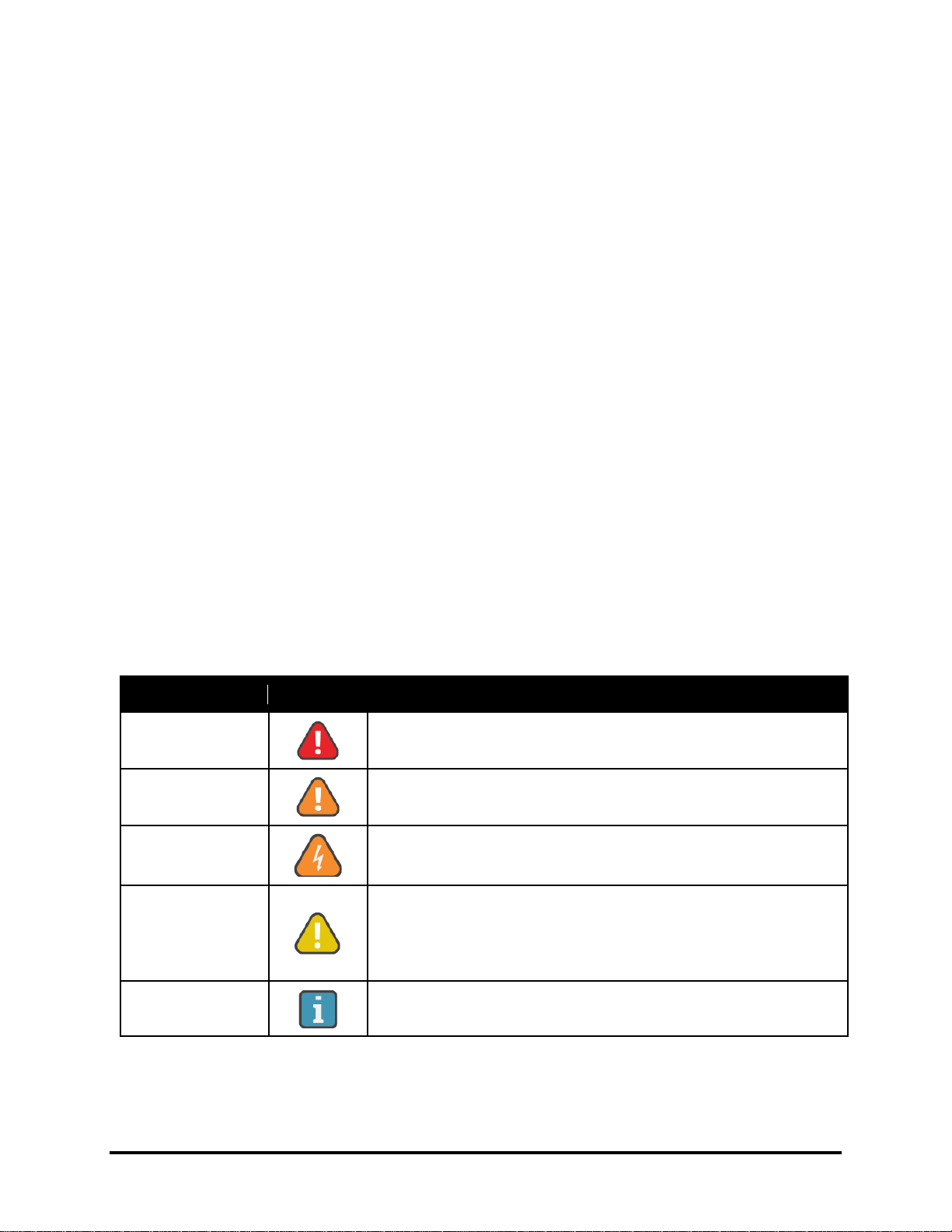
1.2.2 Iconography
Alert
Icon
Description
Danger
Imminently hazardous situation which, if not avoided, will
result in death or serious injury.
Warning
Potentially hazardous situation which, if not avoided, could
result in death or serious injury.
Warning
Potential electrical shock hazard which, if not avoided, could
result in death or serious injury.
Caution
Potentially hazardous situation which, if not avoided, could
result in physical injury or damage to the product or
environment. It may also be used to alert against unsafe
practices.
Important
Additional information on how to use the product.
Page 8
1100-2294 Rev 1 7
1.3 General Safety Statements
IMPORTANT: Before using this product, carefully read and strictly follow the
instructions in the manual. Ensure that all product documentation is retained and
available to anyone operating the instrument.
DANGER: This instrument is neither certified nor approved for operation in
oxygen-enriched atmospheres. Failure to comply may result in personal injury or
death.
WARNING: Use this product only for the purposes specified in this document and
under the conditions listed.
WARNING: This instrument has not been designed to be intrinsically safe for use
in areas classified as being hazardous locations. For your safety, DO NOT use it in
hazardous (classified) locations.
WARNING: In the event of an alarm or over-range condition, the sensor must be
recalibrated to ensure continued accuracy.
WARNING: This product must be recalibrated if installed in a non-room condition
environment (i.e. temperature or humidity extremes).
WARNING: The gas diffusion path can become occluded (moisture, dust, debris,
frozen condensation) over time resulting in reduced or complete lack of gas
detection and alarming function. Routine visual inspection of the gas detector and
bump testing are suggested to ensure proper gas detection and alarm function.
CAUTION: Except for maintenance detailed in this manual, these products should
only be opened and / or serviced by authorized Bacharach personnel. Failure to
comply may void the warrant.
CAUTION: Operator assumes responsibility for complying with all laws, rules and
regulations governing the use of this product.
CAUTION: Use only genuine Bacharach parts and accessories. Failure to comply
may impair the operation of the product and / or void the warranty.
CAUTION: Only operate the product within the framework of a risk-based alarm
signaling concept.
Page 9

1100-2294 Rev 1 8
1.4 Safe Connection of Electrical Devices
WARNING: Before connecting this instrument to electrical devices not mentioned
in this manual, consult the manufacturer or a qualified professional. Failure to
comply may result in injury and / or damage to the product.
Page 10
1100-2294 Rev 1 9
2. Product Descriptions
2.1 Intended Uses / Applications
MGS-400 gas detectors are to be installed in non-classified, non-hazardous, permanent
locations for the purpose of continuously monitoring ambient air (indoor or outdoor) for the
following gas types:
• Refrigerants
• Oxygen
• Toxic and combustible gases
WARNING: This instrument is neither certified nor approved for operation in
oxygen-enriched atmospheres. Failure to comply may result in EXPLOSION.
WARNING: This instrument has not been designed to be intrinsically safe for use
in areas classified as being hazardous locations. For your safety, DO NOT use it
in hazardous (classified) locations.
2.2 Transmitter Construction
MGS-400 gas detectors may be purchased in the following configurations:
MGS-410
MGS-450
MGS-450
MGS-460
Enclosure
IP66
IP41
IP66
IP66
Relays
- 3 3
3
Communication
Modbus
Modbus
Modbus
Modbus
Output
-
Analog
Analog
Analog
Sensor
Integrated
Integrated
Integrated
Remote
2.3 Power Options
MGS-400 gas detectors may use the following power options:
• 24 VAC
• 19.5 to 28.5 VDC
Page 11

1100-2294 Rev 1 10
2.4 Diagnostic / Status LED
MGS-400 gas detectors feature a three-color LED (green, orange and red) which are used, in
combination with an audible alarm, to communicate the status of the instrument.
2.5 Configurable Output Signals
MGS-400 gas detectors may be connected to a Bacharach’s MGS-408 Gas Detection Controller
or a third-party device capable of accepting digital and/or analog outputs from the gas detectors,
such as a Building Management System (BMS) or Programmable Logic Controller (PLC). With
the integrated audio-visual alarm indication, an instrument can be operated as a stand-alone
unit (with additional local alarm signaling as required). Configurable output signal options
include the following:
MGS-410, MGS-450, MGS-460 – Digital Output (Modbus RTU signal)
MGS-450, MGS-460 – 3× Relays (high alarm / low alarm / fault)
MGS-450, MGS-460 – 1× Analog Output (4 to 20 mA, 0 to 5 V, 0 to 10 V, 1 to 5 V,
2 to 10 V)
2.6 User Interface
MGS-400 gas detectors allow users to interface directly with the instrument via the following:
Bluetooth® Communication (MGS-400 App allows users to configure the gas
detector, initiate calibration, bump test / functional test modes and view status
information.)
Tactile / Magnetic Switches (A non-intrusive magnetic wand allows users to
initiate calibration of the device.)
2.7 Technical Specifications
Category
Specifications
Signals to
Central
Controller
Analog Current
Normal operation:............................................. 4 to 20 mA
Drift below zero:..................................................... 3.8 mA
Measuring range exceeded:................................. 20.5 mA
Instrument fault:.................................................. ≤ 1.2 mA
Fault on analog interface:.................................... > 21 mA
Offline mode/Maintenance signal:....... 3 mA steady signal
Page 12

1100-2294 Rev 1 11
Signals to
Central
Controller
Analog Voltage
0 to 5V; 1 to 5V; 0 to 10V; 2 to 10V (selectable). During
fault condition, 1 to 5V and 2 to 10V outputs are 0V.
Modbus RTU over
RS-485
Baud rate:............................. 9,600 or 19,200 (selectable)
Start bits:......................................................................... 1
Data bits:......................................................................... 8
Parity:.................................. None, odd, even (selectable)
Stop bits:............................................... 1 or 2 (selectable)
Retry time:.................... 500 ms, min time between retries
End of message:............................... Silent 3.5 characters
Power Supply
and Relays
Operating Voltage
19.5 to 28.5 VDC; 24 VAC ± 20%, 50/60 Hz
Inrush Current
1.5 A
Operating Current,
Max.
MGS-410: 2W, 85mA @ 24VDC
MGS-450/60: 4W, 170mA @ 24VDC
Relay Rating
3 SPDT
1A at 30 VAC/VDC, resistive load
Audible Alarm
Internal Buzzer ≥72 dB at 4”
(10 cm)
Alarm Delay
0 to 15 minutes (selectable)
Wiring
Power and Analog
Signal
2-core shielded cable, 16 to 20 AWG (0.5 to 1.5 mm2)
Modbus Network
3-core, 2 twisted pair + ground, shielded cable with 120 Ω
characteristic impedance, 16 to 24 AWG (0.2 to 1.5
mm2).
Cable Gland
M20, 10-14mm cable outer diameter
M16, 4-8mm cable outer diameter
Page 13

1100-2294 Rev 1 12
Physical
Specifications
Enclosure
Protection
IP41 / IP66
Enclosure Size
(W×H×D) (Approx.)
MGS-410: 5.1×5.1×2.7” (130×130×68 mm)
MGS-450 IP41: 6.5× 6.5×3.0” (165×165×77 mm)
MGS-450 IP66: 6.5×6.5×3.4” (165×165×87 mm)
MGS-460: 6.5×6.5×3.4” (165×165×87 mm)
MGS-460 Remote: 4.5× 5.4×2.7” (115×136×68 mm)
Weight (Approx.)
MGS-410: 9.2oz
(260 g)
MGS-450: 1lb, 1oz
(480 g)
MGS-460: 1lb, 11.7oz
(758 g)
Environmental
Temperature
- 40 to 120 ºF (-40 to 50 ºC)
Storage
Temperature
- 5 to 100 ºF (-20 to 40 ºC)
Humidity
5 to 90 %RH, non-condensing
(15 to 90 %RH, non-condensing, EC sensors excl. O2)
Pressure
23.6 to 32.5 inch Hg / 800 to 1,100 mbar
Elevation
0 to 10,000 ft. (3,050 m) altitude
Sensors
See Section 6.3 for sensor specifications.
Influences
For influences on the measurement performance and
restrictions of a particular sensor see sensor data sheet.
Agency
Approvals
CE, EN 50270:2015, UL/CSA/IEC/EN 61010-1
Page 14
1100-2294 Rev 1 13
2.8 Components
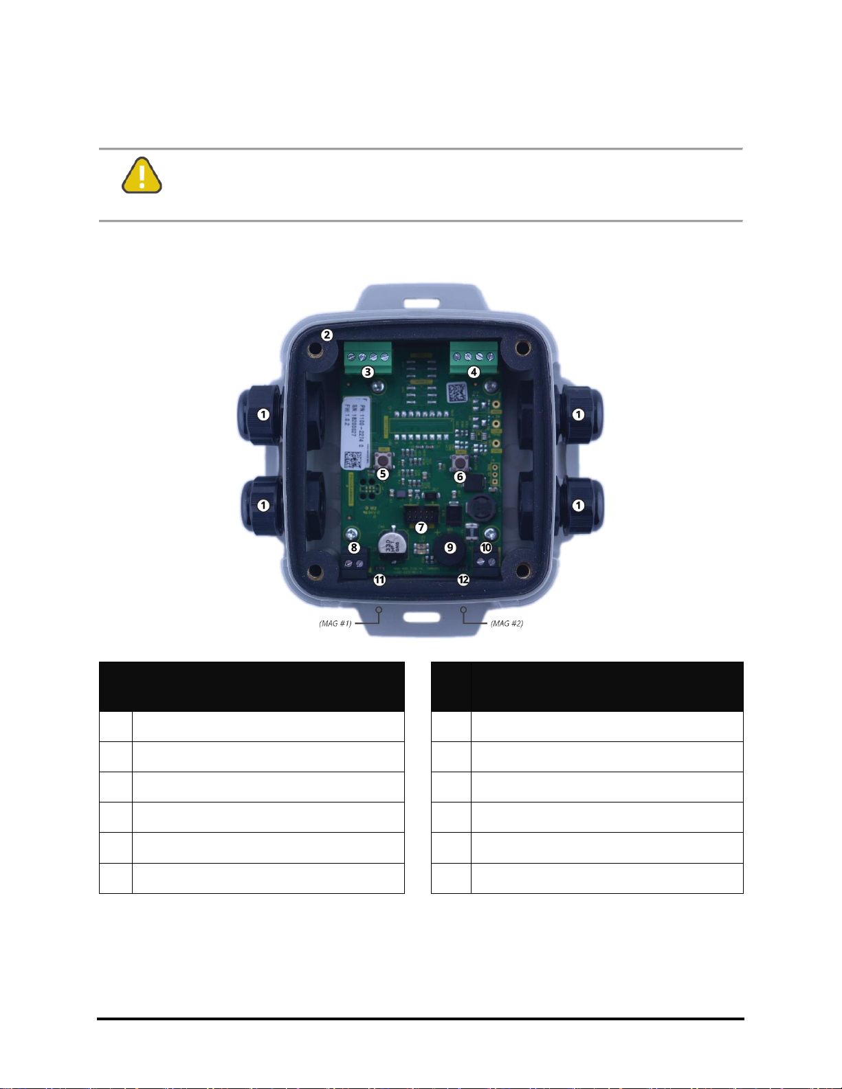
CAUTION: This product uses semiconductors which can be damaged by
electrostatic discharge (ESD). When handling the printed circuit boards (PCBs),
observe proper ESD precautions so that the electronics are not damaged.
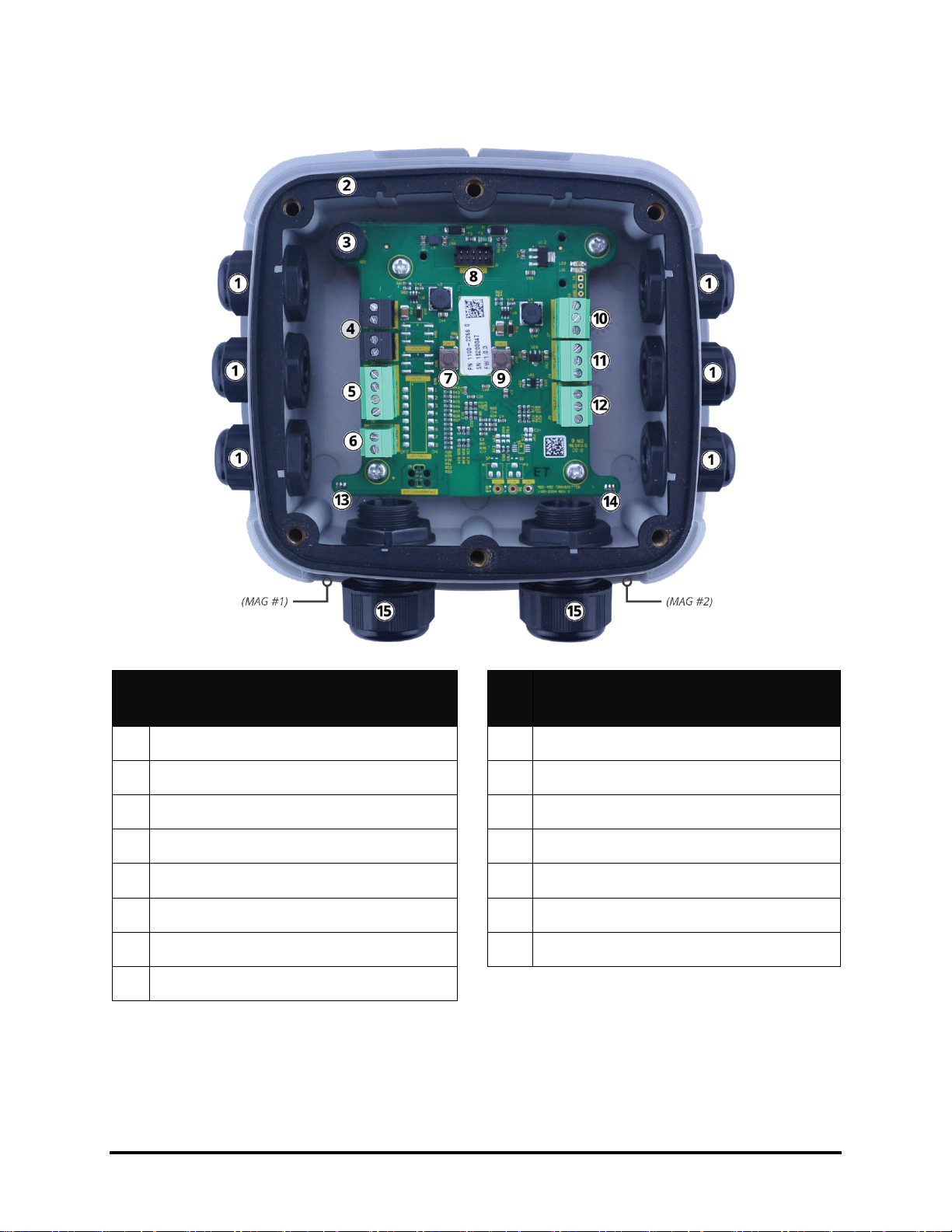
2.8.1 MGS-410 Components
#
Component Description
#
Component Description
1
M16 Cable Glands (×4)
7
Ribbon Cable Connection (To Sensor)
2
Rubber Gasket
8
Power Connection (In)
3
Digital Connection / Modbus (In)
9
Internal Alarm Buzzer
4
Digital Connection / Modbus (Out)
10
Power Connection (Out)
5
Tactile Switch #1
11
Magnetic Switch #1
6
Tactile Switch #2
12
Magnetic Switch #2
Page 15
1100-2294 Rev 1 14
2.8.2 MGS-450 Components
#
Component Description
#
Component Description
1
M16 Cable Glands (×6)
9
Tactile Switch #2
2
Rubber Gasket (IP66 Version Only)
10
Relay 3 Connection (FAULT)
3
Internal Alarm Buzzer
11
Relay 2 Connection (HIGH)
4
Power Connections (×2)
12
Relay 1 Connection (LOW)
5
Digital Connection (Modbus)
13
Magnetic Switch #1
6
Analog Connection
14
Magnetic Switch #2
7
Tactile Switch #1
15
M20 Cable Glands (×2)
8
Ribbon Cable Connection (To Sensor)
Page 16
1100-2294 Rev 1 15
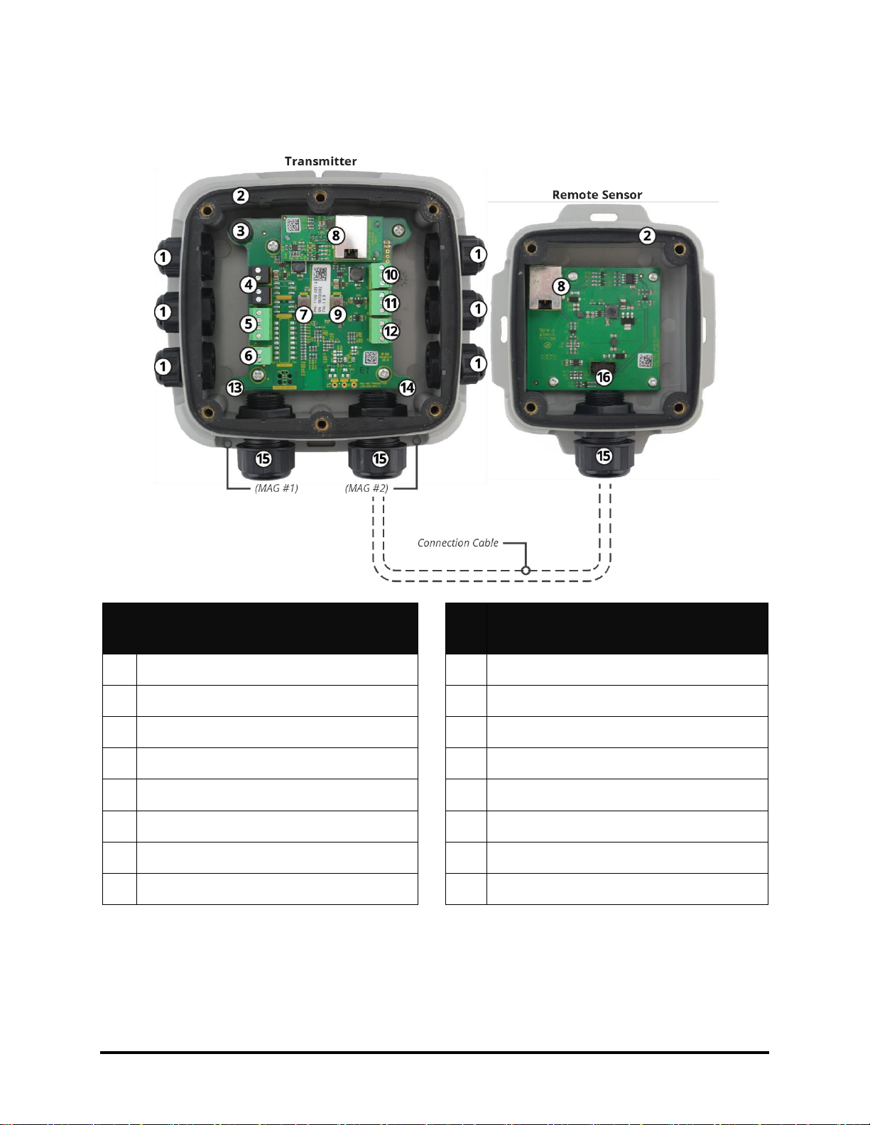
2.8.3 MGS-460 Components
#
Component Description
#
Component Description
1
M16 Cable Glands (×6)
9
Tactile Switch #2
2
Rubber Gasket (×2)
10
Relay 3 Connection (FAULT)
3
Internal Alarm Buzzer
11
Relay 2 Connection (HIGH)
4
Power Connections (×2)
12
Relay 1 Connection (LOW)
5
Digital Connection (Modbus)
13
Magnetic Switch #1
6
Analog Connection
14
Magnetic Switch #2
7
Tactile Switch #1
15
M20 Cable Glands (×3)
8
RJ45 Connects (×2)
16
Ribbon Cable Connection (To Sensor)
Page 17
1100-2294 Rev 1 16
3. Installation
IMPORTANT: The manufacturer of this product requires that a bump test or
calibration be performed following installation to verify instrument functionality.
3.1 General Information
Installation site selection is critical to ensuring system performance and effectiveness. Strict
compliance and considerable thought must be given to every detail of the installation process,
including, but not limited to the following:
● Regulations as well as local, state, and national codes that govern the installation of gas
monitoring equipment
● Electrical codes that govern the routing and connection of electrical power and signal
cables to gas monitoring equipment
● The full range of environmental conditions to which the instruments will be exposed
● The physical characteristics of the gas or vapor to be detected
● The specifics of the application (e.g., possible leaks, air movement/draft, etc.)
● The degree of accessibility required for maintenance purposes
● The types of optional equipment and accessories that will be used with the system
● Any limiting factors or regulations that would affect system performance or installations
● Wiring details, including:
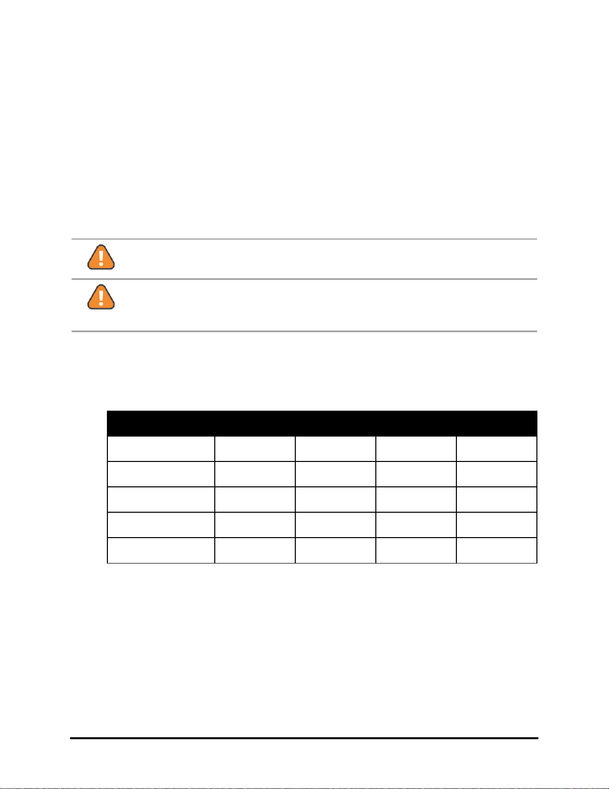
MGS-410
MGS-450
MGS-460
M16 Cable Glands
(4-8mm cable diameter)
4
6
6
M20 Cable Glands
(10-14mm cable diameter)
-
2
1
● Secondary circuit must be supplied from an isolating source
● The wiring for the relays must be selected and fused according to the rated voltages,
currents, and environmental conditions
● If stranded conductors are used, a ferrule should be used
● To comply with RFI immunity regulations, it is necessary to ground the shield of the
communications cable at the PLC, GDA controller, front-end controller, or Building
Management System (e.g., the chassis, the ground bus-bar, etc.).
Page 18

1100-2294 Rev 1 17
3.2 Restrictions
The installation location must have appropriate supply power available for the instrument
(i.e., 19.5 to 28.5 VDC or 24 VAC). This ultimately determines the distance the instrument can
be mounted from the controller or power supply.
3.3 Mechanical Installation
WARNING: DO NOT allow the lid / sensor to hang from the ribbon cable. Failure
to comply may result in damage to the product.
1. Using the provided hardware, securely mount the MGS-400 gas detector according to
the product dimensions, maximum wiring lengths and following considerations:
a. Environment: the full range of environmental conditions when selecting a
location.
b. Application: the specifics of the application (possible leaks, air movement / draft,
etc.) when selecting a location.
c. Accessibility: the degree of accessibility required for maintenance purposes when
selecting a location.
d. Target Gas: the specific gravity of the target gas when selecting the height of the
instrument.
2. Using a 5/32″ (4 mm) hex key / allen wrench (not included) remove the lid and
disconnect the ribbon cable from the base.
3. Set the lid and rubber gasket (IP66-rated enclosures only) aside to be reinstalled later.
3.4 Electrical Installation
3.4.1 Preparations
IMPORTANT: If analog output is configured for 4 to 20 mA output, ensure that
the current loop is connected to a sinking current loop monitor before powering
on the instrument. Otherwise, a fault may be displayed indicating an open loop
condition. If analog output is unused, ensure it is configured as a voltage output
(default: 1-5V) to prevent an open loop fault condition. The analog output is
designed as sourcing.
CAUTION: Ensure wiring for relays and connections for sensor(s) are made
before applying power.
CAUTION: This product uses semiconductors which can be damaged by
electrostatic discharge (ESD). When handling the printed circuit boards (PCBs),
observe proper ESD precautions so that the electronics are not damaged.
Page 19

1100-2294 Rev 1 18
3.4.2 Power & Signal Wiring
1. Locate the relevant connections (Power, Analog, Modbus) and remove the terminal
block from the PCBA. (The PCB terminal blocks are pluggable type and may be
removed to aid termination.)
Connection
Description
Label
Wiring Termination
Power
24 VDC/VAC IN
24V IN: -
24 VDC/VAC neutral /
ground
24V IN: +
24 VDC positive / VAC live
24 VDC/VAC OUT
(power daisy chain
terminal)
24V OUT: -
24 VDC/VAC neutral /
ground
24V OUT: +
24 VDC positive / VAC live
Digital Output
Modbus Network
Communications
MODBUS: B
RS-485 “B” (inverted)
MODBUS: A
RS-485 “A” (non-inverted)
MODBUS: GND
RS-485 GND
MODBUS: SH
RS-485 Shield
Analog Output
Voltage or Current
Output
ANALOG: -
Analog output ground
ANALOG: +
Analog output signal (+)
2. Remove plugs from the corresponding M16 cable glands.
The product comes with cable glands and plugs pre-installed. (The power entry
cable gland is shipped from the factory without a plug.)
3. Using the appropriate cable glands, insert wires into the enclosure.
4. Secure the wires in each terminal block and, pressing firmly, reinstall the terminal block
into the PCBA.
Polarity must not be reversed.
For 24 VAC installations in a daisy-chain configuration, the neutral polarity must
be maintained for all instruments.
5. Remove all excess cable from the housing before securing the cable glands.
Page 20

1100-2294 Rev 1 19
3.4.3 Relay Wiring
WARNING: Relays are rated for 0 to 30V AC/DC. DO NOT apply mains power
onto these relays.
1. Locate the relevant connections (Relay 1, Relay 2, Relay 3) and remove the terminal
block from the PCBA.
Relay
Function
1
Low Alarm
2
High Alarm
3
Fault Alarm
2. Remove plugs from the corresponding M16 cable glands.
3. Using the appropriate cable glands, insert wires into the enclosure.
4. Secure the wires in each terminal block and, pressing firmly, reinstall the terminal block
into the PCBA.
5. Remove all excess cable from the housing before securing the cable glands.
When configured according to the factory default settings, the relays are de-energized during
normal operation (not fail-safe). Fail-safe mode can be configured. When configured for fail-safe
operation, relays are energized during normal operation. Fail-safe operation ensures relays are
triggered in cases of power failure at the instrument. In failsafe operation normally open and
normally closed terminals are reversed as indicated by the following table:
Terminal
Normal operation
Failsafe Operation
NC
Normally Closed
Normally Open
COM
Common
Common
NO
Normally Open
Normally Closed
3.4.4 Installation of Remote Sensing Head
IMPORTANT: Non standard cable lengths less than 5 meters may be used.
Where non standard remote cables are used these must be shielded to comply
with EMI regulations.
IMPORTANT: Remote sensor is automatically recognized and registered by the
instrument after a power cycle.
Page 21

1100-2294 Rev 1 20
The MGS-460 features a remote sensor, which allows users to detect the presence of gases in
inaccessible locations. Standard RJ45 “Cat 5E STP” Ethernet cable up to 5 meters long
(included) may be used with the remote sensor.
1. Remove the bottom right M20 cable gland plug and gland cap, and carefully remove the
gland rubber insert. (The rubber insert is split to allow it to be installed around the
provided RJ45 cable.)
2. Slip the cable gland nut over one end of the terminated RJ45 cable.
3. Apply the split rubber insert onto the cable so that it is between the gland nut and the
end of the cable.
4. Feed the RJ45 connector through a cable gland and into the enclosure, taking care to
not damage the PCB.
5. Remove all excess cable from the housing before securing the cable gland. (Confirm
that the RJ45 cable is not binding or stressing the PCB terminal block.)
6. Plug the RJ45 connector into the provided RJ45 socket.
3.4.5 Connecting to MGS-408 Gas Detection Controller
For wiring and configuration information, please refer to the manual which is included with the
MGS-408 (P/N: 1100-2295).
At the central control system, connect the shield of the wires to the earth ground of the
controller (e.g., the chassis, the ground bus-bar, etc.).
For 24 VDC installations, the input is protected. If the polarity is reversed, the instrument
will not power-up.
For 24 VAC installations in daisy-chain, the neutral polarity must be maintained for all
instruments.
3.4.6 Modbus RTU RS-485 Interface
For the Modbus RS-485 network use a 16 to 24 AWG (0.2 to 1.5 mm2) 3-core, 2 twisted pair +
ground, shielded cable with 120 Ω characteristic impedance. (Recommended: Belden 3106A or
equivalent.)
The Modbus address, baud rate, stop bit, parity and slave termination is configured through the
setup menu. No jumpers or hardware switch settings are required.
Ensure that the communication parameters within the network, including the Building
Management System, are configured identically.
To ensure optimal performance of the Modbus network, ensure the following guidelines are
implemented:
● Instruments are configured in a single bus topology, connecting multiple buses in parallel
or branching multiple units from the main bus, may introduce impedance mismatches,
reflections and/or signal distortions.
● Avoid long stubs when connecting instruments to the bus (stubs should be less than 1
meter in length).
Page 22

1100-2294 Rev 1 21
● Instruments at end of bus have 120Ω terminating resistor enabled. Terminating resistors
may be enabled via the MGS-400 App (refer to Section 4.2.3.6 for more information).
● A/B signal polarity is maintained throughout RS-485 network.
● Connect cable shield drain to physical earth or ground at the controller only.
● Connect cable shield drain to (SH) terminal at instrument.
● Cable shield integrity is maintained throughout RS-485 network.
● Do not use shield connection for signal ground. Use cable that provides dedicated
ground conductor for signal ground. Connect signal ground to (GND) terminal of
instrument.
3.4.7 Confirming Instrument Functionality
After all wiring has been completed, power the transmitter and perform a calibration / bump test
to verify instrument functionality:
1. Switch power on.
2. Allowing the instrument to complete its start-up sequence and the sensor to stabilize.
3. Perform a calibration or bump test to confirm instrument functionality. (For instructions
on performing a calibration or bump test, see Section 5.2.)
4. After verifying instrument functionality, reinstall the enclosure lid.
Reinstall the rubber gasket in the transmitter and / or remote sensor. Ensure that
it is seated correctly before replacing lid. (Note that the IP41-rated configurations
do not include a rubber gasket.)
Using a 5/32″ (4 mm) hex key / allen wrench (not included) tighten the lid screws
in an “X” tightening pattern. (Tightening torque should be limited to hand tight,
and should be uniform.)
Page 23

1100-2294 Rev 1 22
4. Operation
4.1 Overview of Normal Operation
WARNING: Before leaving the instrument for normal operation, check the
configuration for proper settings and check calibration.
4.1.1 Applying Power & the Start-up Sequence
After applying power, the instrument will go through a start-up sequence (initialization,
audible/visual test and self-test sequence). After start-up sequence completes, the instrument
will enter a warm-up period to allow the sensor element to stabilize before reporting a valid
output.
1. Switch power on.
2. Observe the start-up sequence and warm-up phase:
Green LED will blink at 0.5 HZ for about 5 minutes.
Modbus flag for warm-up is set.
Buzzer is off.
Relay state is “no alarm.”
Gas reading is invalid.
3. Observe normal operation:
Green LED is steady on.
Modbus flag for warm-up is cleared.
Buzzer is off.
Relay state is “no alarm.”
Gas reading is valid.
4.1.2 Verifying Analog Signals
MGS-450 / 460 gas detectors feature a single configurable analog output. During normal
operation, the analog output of the instrument is proportional to the detected gas concentration.
Output level is proportional to the gas level as shown below:
Gas Concentration
1-5V
0-5V
2-10V
0-10V
4-20mA
0%
1V
0V
2V
0V
4 mA
50%
3V
2.5V
6V
5V
12 mA
100%
5V
5V
10V
10V
20 mA
Page 24

1100-2294 Rev 1 23
The instrument may also enter several special states, these are indicated by the specific analog
output levels indicated below:
Mode of Operation
1-5V
0-5V
2-10V
0-10V
4-20mA
Instrument Fault
≤ 0.3V
N/A
≤ 0.6V
N/A
≤ 1.2 mA
Offline Mode / Maintenance
0.75V
N/A
1.5V
N/A
3 mA
Drift Below Zero
0.95V
N/A
1.9V
N/A
3.8 mA
Normal Operation
1-5V
0-5V
2-10V
0-10V
4-20 mA
Measuring Range Exceeded
5.12V
5.12V
10.25V
10.25V
20.5 mA
Fault on Analog Interface
> 5.25V
> 5.25V
> 10.5V
> 10.5V
> 21mA
4.1.3 Verifying the Modbus Signal
The MGS-400 gas detectors provide a Modbus RTU digital interface. All status messages and
most parameters can be accessed and / or configured via the MGS-400 App (Bluetooth®
communications) or via a Building Management (Modbus network).
Page 25

1100-2294 Rev 1 24
4.1.4 Status Indication
The MGS-400 gas detectors provide external indication of their current operational state via
audible and visual feedback. (MGS-450 / 460 gas detectors also provide relays outputs.) Visual
indication of the instrument status is provided by a single tri-color LED (Green / Red / Orange)
as indicated below:
State
LED
Buzzer
Relay 1
(LOW)
Relay 2
(HIGH)
Relay 3
(Fault)
Warm-up
OFF
OFF
OFF
Normal
OFF
OFF
OFF
Low Alarm
ON
OFF
OFF
High Alarm
ON
ON
OFF
Offline
OFF
OFF
OFF
Fault
OFF
OFF
ON
Negative Gas Fault
OFF
OFF
ON
Zero Cal. Fault
OFF
OFF
OFF
Span Cal. Fault
OFF
OFF
OFF
4.1.5 Switch Functions
User interaction with the MGS-400 gas detector is accomplished through the use of two
magnetic switches located on the bottom of each unit. To actuate a magnetic switch (referred to
as MAG#1 or MAG#2), apply the supplied magnetic wand (P/N: 1100-1004) to the relevant
switch location as indicated below:
Page 26

1100-2294 Rev 1 25
Depending on the duration the switch is held, a short “TAP” or long “HOLD” will be detected:
To carry out a tap function, tap the relevant switch location for 1 second, until a single
“chirp” is heard, remove wand to confirm a “TAP.”
To carry out a hold function, do not remove the magnetic wand after the first chirp but
continue to hold for >5 seconds, until a double “chirp” is heard, remove wand to confirm
a “HOLD.”
If either switch is held for >30s, a stuck switch fault will be indicated.
To interact with the instrument without use of the magnetic wand, two internal push button
tactile switches may be used. Remove lid without removing ribbon cable to access. Internal
switches TACT#1 and TACT#2 mirror the functions of MAG#1 and MAG#2.
The function of each switch depends on the current state of the instrument as indicated in the
following table:
State
Switch 1
(Tap)
Switch 1
(Hold)
Switch 2
(Tap)
Switch 2
(Hold)
Warm-up
Enable
Bluetooth®
Connectivity
-
Disable
Bluetooth®
Connectivity
-
Normal
Start Zero Calibration
Start Span
Calibration
Low Alarm
Mute Buzzer
Ack. Latched Alarm
High Alarm
Mute Buzzer
Ack. Latched Alarm
Offline - -
Fault
Mute Buzzer
Ack. Latched Fault
Negative Gas
Fault
Mute Buzzer
Start Zero
Calibration
Zero Cal. Fault
Acknowledge Fault
-
Span Cal. Fault
-
Acknowledge Fault
4.1.6 Reset System to Factory Default Settings
To reset system to factory defaults, remove lid and hold TACT#1 and TACT#2 simultaneously
for 30 seconds. Instrument will restart to confirm factory reset. Alternatively, see Section 4.2.3.4
“Reset to Factory Defaults”, for instructions on resetting instrument configuration via the MGS400 App.
Page 27

1100-2294 Rev 1 26
4.2 MGS-400 Smartphone Application
To download the MGS-400 App, visit www.mybacharach.com/apps. The companion
smartphone application allows users to perform a variety of functions to configure and interact
with the MGS-400 gas detector, including:
● View real-time measurements
● Configure instrument
● Test outputs
● Calibrate / bump test instrument
● Generate customizable calibration certificates
4.2.1 Enable Bluetooth® Connection
1. Enable Bluetooth® discovery by tapping MAG#1 for 1-second. (After 10-seconds, device
will indicate that it is discoverable with audible heartbeat until it has been paired,
discovery has timed-out or has been cancelled.)
2. Launch the MGS-400 App and click the Bluetooth® icon at the bottom of the screen to
initiate a scan.
3. Select the instrument from the list of available Bacharach gas detectors.
MGS-410 default alias is “18TMA-DT”
MGS-450 / 460 default alias is “18TMA”
4. When prompted, enter the passkey (default is “123456”).
WARNING: Default alias, passkey and unlock code can be changed via the
MGS-400 App’s configuration menu. Default values should be changed after
instrument installation for security purposes.
4.2.2 Checking Status
Current instrument status can be viewed from the Home tab, including the following:
Page 28

1100-2294 Rev 1 27
#
Description
1
Alias - user configured instrument
name
2
Serial Number - instrument 8 digit
serial number
3
Gas - gas type currently detected
by instrument
4
Status Ring - provides visual
indication of various instrument
states (expanded on below)
5
Live Measurement - current
measurement in given
measurement units
6
Measurement Unit - displayed
measurement unit (PPM / PPB /
%LEL / %VOL)
State
Status Ring
Description
Warm-up
Green
Gas detector stabilizing after power on or restart
Normal
Green
Normal operation
Low Alarm
Yellow
Gas measurement has exceeded low alarm setpoint
High Alarm
Red
Gas measurement has exceeded high alarm setpoint
Offline
Orange
Gas Detector in maintenance mode and is not actively
monitoring gas
Fault
Orange
A fault has been detected
Negative Gas
Fault
Orange
Gas detector calibration has drifted below zero, requires
zero calibration
Zero Cal. Fault
Orange
Error occurred during zero calibration. Zero calibration
has not be updated. Zero calibration required.
Span Cal. Fault
Orange
Error occurred during span calibration. Span calibration
has not be updated. Span calibration required.
Page 29

1100-2294 Rev 1 28
4.2.3 Instrument Configuration
For security, access to configuration and calibration options are restricted to authorized users
only. Access to these functions require use of an unlock code. To unlock instrument
configuration:
Configure Tab When prompted, enter unlock code to access device configuration.
(The instrument’s default code is “1234”). Instrument will remain unlocked until
Bluetooth® connection has ended.
WARNING: Default alias, passkey and unlock code can be changed via the
MGS-400 App’s configuration menu. Default values should be changed after
instrument installation for security purposes.
4.2.3.1 Change Alias
To allow easy identification of a given instrument, an alias can be assigned to each instrument.
This alias is displayed when searching for an instrument via Bluetooth®, on calibration cert and
in home tab. To set alias:
Configure Tab Alias, Enter required alias for instrument, select OK.
Instrument must be restarted for change to take effect. Home Tab Restart, will reboot
device.
Reconnect to instrument to confirm alias has been updated.
4.2.3.2 Change Unlock Code
To prevent unauthorized access to instrument configuration and calibration, default instrument
unlock code should be changed during commissioning. To change unlock code:
Configure Tab Modbus Unlock Code, enter new 4-digit unlock code for instrument,
select OK.
Instrument must be restarted for change to take effect. Home Tab Restart, will reboot
device.
Reconnect to instrument to confirm unlock code has been updated.
IMPORTANT: If custom unlock code is forgotten, unlock code may be reset to
default value (1234) by resetting system to factory defaults. Refer to section
4.1.6 for system reset procedure. Note system reset will return all custom system
configurations to defaults
4.2.3.3 Change Bluetooth Passcode
To prevent unauthorized access to instrument status, default instrument Bluetooth® passcode
code should be changed during commissioning. To change Bluetooth® passcode:
Configure Tab Bluetooth Passcode, enter new 6-digit passcode for instrument, select
OK.
Page 30

1100-2294 Rev 1 29
Instrument must be restarted for change to take effect. Home Tab Restart, will reboot
device.
Reconnect to instrument to confirm unlock code has been updated.
IMPORTANT: If custom passcode is forgotten, unlock code may be reset to
default value (123456) by resetting system to factory defaults. Refer to section
4.1.6 for system reset procedure. Note system reset will return all custom system
configurations to defaults.
4.2.3.4 Reset to factory defaults
Instrument configuration may be reset to factory defaults via the smartphone application:
Configure Tab Reset to factory default, select OK to confirm.
Instrument will automatically restart and disconnect from smartphone application.
WARNING: Resetting system to factory defaults will remove all custom system
configuration including unlock code and Bluetooth passcode. After system reset
custom unlock and Bluetooth passcodes should be configured to prevent
unauthorized access and reconfiguration of instrument.
4.2.3.5 Alarm Configuration
Low Alarm Setpoint
Value above which a low alarm condition occurs. Low alarm setpoint must be less than the high
alarm setpoint and greater than the low alarm limit. The low alarm limit is the fixed minimum limit
that is sensor–specific and not editable.
Range of acceptable setpoints is displayed when updating parameter. To update setpoint:
Configure Tab Alarm Low Alarm Setpoint, enter new setpoint, select OK to confirm.
IMPORTANT: In instruments with an oxygen sensor installed, low alarm
behavior operates in a depletion mode where gas measurements BELOW the
low alarm setpoint initiate a low alarm. This allows monitoring of oxygen
displacement and enrichment scenarios.
IMPORTANT: To prevent intermittent alarm operation at the setpoint due to
measurement noise this instrument implements hysteresis at the setpoint. Once
the alarm level is exceeded, the gas measurement must return a fixed
percentage below the alarm threshold before the alarm is disabled. Typical
hysteresis value is set at 5% of full scale however this is sensor specific and
non-editable.
Page 31

1100-2294 Rev 1 30
High alarm Setpoint
Value above which a high alarm condition occurs. High alarm setpoint must be less than the
sensor full scale range and greater than the low alarm setpoint.
Range of acceptable setpoints is displayed when updating parameter. To update setpoint:
Configure Tab Alarm High Alarm Setpoint, enter new setpoint, select OK to confirm.
IMPORTANT: To prevent intermittent alarm operation at the setpoint due to
measurement noise this instrument implements hysteresis at the setpoint. Once
the alarm level is exceeded, the gas measurement must return a fixed
percentage below the alarm threshold before the alarm is disabled. Typical
hysteresis value is set at 5% of full scale however this is sensor specific and
non-editable.
Alarm Latching
Enabling alarm latching will maintain alarm or fault condition even after the alarm or fault
condition is no longer active. When latched, the alarm or fault condition must be manually
acknowledged before the condition will be cleared. This allows transient alarm or fault
conditions to be identified.
If an alarm is latched, i.e. the condition has occurred but is no longer active, an
acknowledgement button will appear on the home screen. Select this button to acknowledge the
latched condition and clear the alarm or fault.
When disabled the alarm or fault status clears automatically as soon as the condition is no
longer active. To configure:
Configure Tab Alarm Alarm Latching, select enable/disable, select OK to confirm
4.2.3.6 Modbus Configuration
Address
Sets instrument address for connection to RS-485 Modbus interface. (Default: 1).
To set address:
Configure Tab Modbus Address, select 1-247, select OK to confirm
IMPORTANT: Ensure all instruments on RS-485 bus have been configured with
unique node addresses. If two instruments have been configured with same
address, bus contention will occur preventing communications with these
instruments via the RS-485 interface.
Page 32

1100-2294 Rev 1 31
Baud Rate
Sets instrument baud rate for connection to RS-485 Modbus interface. (Default: 9600 baud) To
set baud rate:
Configure Tab Modbus Baud Rate, select 9600/19200, select OK to confirm
Stop Bits
Sets instrument stop bits for connection to RS-485 Modbus interface. (Default: 1 stop bits) To
set number of stop bits:
Configure Tab Modbus Stop Bits, select 1 or 2, select OK to confirm
Parity
Sets instrument parity for connection to RS-485 Modbus interface. (Default: None) To set parity:
Configure Tab Modbus Parity, select None/Odd/Even, select OK to confirm
IMPORTANT: Stop bits must be set to 1 where parity is odd or even.
Enable 120Ω Termination
For optimal communication reliability, in RS-485 Modbus networks the last instrument physically
connected to the RS-485 bus must include a 120Ω termination resistor. This is to reduce the
potential for electrical signal reflection on long buses due to impedance mismatches.
Typically, this requires a physical resistor with the same characteristic impedance of the bus
cable to be installed on the bus.
MGS-400 instruments include this termination resistor on all instruments and allow this
termination to be enabled via this configuration setting without the need for an external physical
resistors. To enable this termination resistor:
Configure Tab Modbus Enable 120Ω Termination, select enable/disable, select OK
to confirm
IMPORTANT: Termination resistor should only be enabled on last instrument
physically connected to RS-485 bus. An external resistor should not be
connected where this is enabled on the instrument.
4.2.3.7 Output Configuration
Analog Output Range
Sets instrument analog output range. Available ranges: 1-5V (Default), 0-5V, 0-10V, 2-10V, 420mA. To set range:
Configure Tab Outputs Analog Output Range, select desired range, select OK to
confirm
Page 33

1100-2294 Rev 1 32
Buzzer
Enable or disable buzzer. Buzzer provides local audible alarm/fault indication. Buzzer is enabled
by default. To enable/disable buzzer:
Configure Tab Outputs Buzzer, select enable/disable, select OK to confirm
Relay Failsafe
Enable or disable Relay Failsafe operation. When configured for fail-safe operation, relays are
energized during normal operation. Fail-safe operation ensures relays are triggered in cases of
power failure at the instrument. In failsafe operation normally open and normally closed
terminals are reversed as indicated in Section 3.4.3.
Relays are configured as non-failsafe by default. To enable/disable relay failsafe:
Configure Tab Outputs Relay Failsafe, select enable/disable, select OK to confirm
Alarm Delay
Sets delay in minutes before instrument will indicate an alarm condition after low or high alarm
threshold has been exceeded. May be used to prevent short transient alarm conditions from
activating alarms. Alarm delays may be set for 0-15 minutes. Alarm delay is configured as 0
minutes by default. To set alarm delay:
Configure Tab Outputs Alarm Delay, enter desired delay in minutes (0-15), select
OK to confirm.
Analog Zero Adjust
Analog zero adjust applies a fixed offset to the analog output. This allows removal of small
errors in the output between the gas detection instrument and the measurement at the controller
due to cable resistance when using voltage outputs.
NOTE: MGS-408 controller uses digital interface, this analog adjustment is only
required where using third party controller using analog interface for gas
concentration and status monitoring.
To apply adjustment ensure instrument is outputting fixed voltage (default 1V at zero ppm or
use output test function to set specific voltage value), monitor remote measurement and adjust
zero offset until remote measurement matches expected voltage output.
Adjustment is limited to ±10% full scale To set analog zero adjustment:
Configure Tab Outputs Analog Zero Adjust, use slider to set desired offset
adjustment.
Alternatively, tap “Analog Zero Adjust (X.X%)” text and enter specific offset required (-10
to 10)
Page 34

1100-2294 Rev 1 33
Analog Span Range
Analog span range scales the FSD (full-scale deflection) of the analog output. The selected
range determines the equivalent gas measurement at the analog output maximum range.
Example: R134A 1000 ppm, 0-5V analog output. If Analog Span Range is set to 20%, the full
analog output range only covers the first 20% of the gas measurement range, i.e 0-200 ppm will
output 0-5V, above 200 ppm the output will be truncated to 5V.
Note, sensor resolution stays at the value for the max range.
Adjustment is limited to between 20%-100% FSD, Default is set to 100%. To set analog span
range:
Configure Tab Outputs Analog Span Range, use slider to set desired range
Alternatively, tap “Analog Span Range (X.X%)” text and enter specific range required.
Page 35

1100-2294 Rev 1 34
5. Care & Maintenance
5.1 Maintenance Intervals
Interval
Function
During
Commissioning
Check calibration.
Check LEDs for proper operation.*
Check for proper buzzer and relay operation.*
Check signal transmission to the BMS/BAS (central controller) if
connected.*
Every 6-12
Months**
Inspection by trained service personnel.
Check LEDs for proper operation.*
Check for proper buzzer and relay operation.*
Check signal transmission to the BMS/BAS (central controller) if
connected.*
Calibrate the sensor or contact Bacharach for sensor exchange with
factory‑ calibrated sensor.
As Required
Replace sensor module(s)
* Feature may be activated via Modbus commands or MGS-400 App.
** Typical maintenance frequency may vary by sensor type.
Page 36

1100-2294 Rev 1 35
Sensor Type
Maintenance Interval
Typical Sensor Lifetime
Electrochemical* 12 months
2-3 years
Catalytic Bead
Zero calibration -1-3 months
Span calibration - 6 months
5-7 years
Semiconductor*
6 months after commissioning
12 months thereafter
4-6 years
Infrared
12 months
5-7 years
* Sensors should be checked after exposure to significant concentrations of gas,
which can shorten the sensor lifetime and/or reduce its sensitivity.
5.2 Adjustments
5.2.1 Introduction
Adjustment of the detector must be performed at regular intervals as required by national
standards or regulations (e.g., EN 378, ASHRAE 15, BREEAM, etc.).
Breathing Hazard: Calibration gas MUST NOT be inhaled! See appropriate Safety Data
Sheets. Calibration gas should be vented into a fume hood or to the outside of the building.
Zero First, Then Span: For proper operation, never adjust the span before completing a zero
adjustment. Performing these operations out of order will cause faulty calibration.
IMPORTANT: Bacharach recommends calibrating detectors within the
application-specific condition and with target gas. This method of zeroing the
detector in the application environment and performing a target gas calibration is
more accurate. A surrogate gas calibration may only be performed as an
alternative if a target gas calibration is not possible.
IMPORTANT: The sensor should be fully stabilized (at least 2 hours, preferably
24 hours).
IMPORTANT: When entering the functions for zero or span adjustment, the
detector will automatically enter OFFLINE mode, and will remain OFFLINE until
either the OFFLINE mode is canceled by tapping the respective magnetic switch,
or the OFFLINE mode times out within 6 minutes (typical) after the adjustment
has ended.
Page 37

1100-2294 Rev 1 36
5.2.2 General Calibration Procedure
WARNING: The MGS-400 Gas Detector MAY NOT be in an alarm or fault
condition during calibration. Acknowledge any alarms or faults BEFORE
attempting to begin the calibration process.
WARNING: Except for CO2 or O2 sensors, calibration gas must be in a balance
of air, not nitrogen (N2).
IMPORTANT: Calibration and / or bump testing requires the MGS-400
calibration adapter kit (P/N: 6302-9990).
IMPORTANT: At elevations higher than 6,560’ (2,000 m), calibration will result in
a lower reading. Above 6,560’, the instrument should be calibrated in the
environment of operation.
1. Fit calibration adapter to the gas detector lid.
2. If using a variable flow regulator, adjust the gas flow to approximately 0.3 L/min.
5.2.3 Zero Adjustment
Ambient air can be used to zero the sensor instead of synthetic air only if the area is known to
be free of the target gas or any gas to which the sensor may be cross-sensitive. In this case, no
cylinder or calibration adapter is needed for the zero adjustment.
WARNING: The MGS-450 MAY NOT be in an alarm or fault condition during
calibration. Acknowledge any alarms or faults BEFORE attempting to begin the
calibration process.
WARNING: Except for CO2 or O2 sensors, ambient air may be used instead of
zero gas if the area is know to be free of the target gas or any gases to which
the sensor may be cross-sensitive.
IMPORTANT: Calibration and / or bump testing requires the MGS-400
calibration adapter kit (P/N: 6302-9990).
1. Begin zero adjustment:
a. MGS-400 App: Home Tab
Calibrate scan barcode on gas cylinder or manually
enter values for zero gas.
b. Manual: hold MAG#1 for >5-seconds. The LED will blink green-green-red when
the instrument is ready.
2. Apply zero gas (or ambient air per warning above).
3. Confirm the start of calibration:
a. MGS-400 App: press the Start Zero button.
Page 38

1100-2294 Rev 1 37
b. Manual: tap MAG#1 within 30-seconds or the instrument will time-out and return
to normal operation.
4. Complete zero adjustment:
a. MGS-400 App: app will countdown to completion. If calibration is successful,
proceed to Step 5. If calibration is unsuccessful, return to the Home screen and
press the Acknowledge button to clear the zero calibration fault.
b. Manual: the LED will blink green-red, green-red-red, green-red-red-red, etc. until
calibration is complete. To abort, hold MAG#1 for >5-seconds, turn off gas flow
and remove the calibration adapter. If calibration is successful (green LED),
proceed to Step 5. If calibration is unsuccessful (LED blinks orange @ 2 Hz), tap
MAG#1 to discard the calibration attempt.
5. Turn off gas flow from zero gas.
6. Replace zero gas with calibration gas in preparation for span adjustment.
5.2.4 Span Adjustment
WARNING: Except for CO2 or O2 sensors, calibration gas must be in a balance
of air, not nitrogen (N2).
IMPORTANT: At elevations higher than 6,560’ (2,000 m), calibration will result in
a lower reading. Above 6,560’, the instrument should be calibrated in the
environment of operation.
1. Begin span adjustment:
a. MGS-400 App: scan barcode on gas cylinder or manually enter values for
calibration gas.
b. Manual: hold MAG#2 for >5-seconds. The LED will blink green-green-orange
when the instrument is ready.
2. Apply calibration gas at the concentration listed on the calibration gas concentration
label (located on top of the instrument).
Part Number
Serial Number
Sensor Type
Maximum Range
3. Confirm the start of calibration:
a. MGS-400 App: press the Start Span button.
b. Manual: tap MAG#2 within 30-seconds or the instrument will time-out and return
to normal operation.
4. Complete span adjustment:
a. MGS-400 App: app will countdown to completion. If calibration is successful,
proceed to Step 5. If calibration is unsuccessful, return to the Home screen and
press the Acknowledge button to clear the span calibration fault.
Page 39

1100-2294 Rev 1 38
b. Manual: the LED will blink green-orange, green-orange-orange, green-orange-
orange-orange, etc. until calibration is complete. To abort, hold MAG#2 for >5seconds, turn off gas flow and remove the calibration adapter. If calibration is
successful (LED blinks green-orange-red), proceed to Step 5. If calibration is
unsuccessful (LED blinks orange @ 2 Hz), tap MAG#2 to discard the calibration
attempt.
5. Turn off gas flow from calibration gas and remove the calibration adapter.
6. Allow sensor to recover / stabilize before the instrument returns to normal operation
(green LED).
5.2.5 System Bump Test
IMPORTANT: The manufacturer of this product requires that a bump test or
calibration be performed following installation to verify instrument functionality.
A bump test is a live test of the system to verify that the detector responds to gas and all
connected alarm devices, BMS, etc. are operating accordingly. It is recommended that all
involved persons are informed about the test and certain alarms might have to be inhibited
(e.g., shutdown valves, notification of authorities, etc.).
1. Connect adapter and gas cylinder according to the instructions in the General
Calibration Procedure.
2. If desired, disable / silence external annunciators (e.g., shutdown valves, notification of
authorities, etc.):
a. MGS-400 App: Home Tab Calibrate Bump toggle TAKE OFFLINE to
disable communications to external devices.
b. Manual: Inform building personnel of test so that external devices can be
disabled / silenced.
3. Apply a sufficiently high concentration of the target gas to trigger alarms, but NOT pure
refrigerant or hydrocarbons (e.g., do not use a butane lighter).
4. Once thresholds have been exceeded, relays should activate, digital outputs should
transmit the gas concentration and:
a. MGS-400 App: gas concentration should be displayed, the instrument status
should be “LOW ALARM” or “HIGH ALARM” and alarms states should be “ON.”
b. Manual: LED status should display “LOW ALARM” or “HIGH ALARM.”
5. Turn off gas flow and remove the calibration adapter.
6. Allow sensor to recover / stabilize before the instrument returns to normal operation
(green LED).
Page 40

1100-2294 Rev 1 39
5.3 Troubleshooting
5.3.1 Hexadecimal Format
All fault codes can be retrieved through the Modbus interface and are shown in hexadecimal (hex)
format. A hex digit can represent multiple codes as shown below:
Hex
Code
Equivalent
Error Code(s)
0 0 1 1 2
2
3
1+2 4 4 5 1+4
Hex
Code
Equivalent
Error Code(s)
6
1+2+3
7
1+2+4
8
8
9
1+8
A
2+8
B
1+2+8
Hex
Code
Equivalent
Error Code(s)
D
1+4+8
E
2+4+8
F
1+2+4+8
5.3.3 Fault Codes
NOTICE: If a sensor fault occurs during a gas alarm condition, then the fault
overrides the alarm condition.
Sensor faults may be decoded using the following table. Note that several faults may be reported
at the same time For example, fault code “00000003” is a combination of fault codes 00000001
(No sensor signal) and 00000002 (Voltage out of specification 1V).
NOTICE: If a “last fault” attribute indicates that a fault has occurred at some
point in time, but the corresponding “current fault” attribute shows no fault, then
the problem has self-healed and no service action is required.
Page 41

1100-2294 Rev 1 40
Fault Bit
System Fault
Possible Causes
Required Action(s)
0x00000001
Software fault
Firmware error (e.g.
unexpected state)
Power-cycle.
If it re-occurs, call product
support
0x00000002
Voltage out of
specification 1V
Voltage rail out of range
Call product support
0x00000004
Voltage out of
specification 3.3V
Voltage rail out of range
0x00000008
Voltage out of
specification 5V
Voltage rail out of range
0x00000010
Voltage out of
specification 5.4V
Voltage rail out of range
0x00000020
Voltage out of
specification 12V
Voltage rail out of range
0x00000040
Voltage out of
specification VIN
Voltage rail out of range
0x00000080
System Flash Memory
Read Fault
Error reading from
internal Flash
Power-cycle.
If it re-occurs, call product
support
0x00000100
System Flash Memory
Write Fault
Error writing to internal
Flash
0x00000200
System Flash Memory
CRC fault
Error in internal Flash
CRC
0x00000400
System Invalid
Configuration
Error in system
configuration
0x00000800
GPIO fault
Error detected on GPIO
pin
Call product support
0x00001000
Modbus Fault
Error detected in Modbus
Communications
Power-cycle.
If it re-occurs, call product
support
0x00002000
Analog Output Fault
(MGS-450 Only)
Error updating DAC value
0x00004000
Bluetooth Fault
Error detected in
Bluetooth module
0x00008000
Stuck switch
Magnetic and/or Tactile
switch activated for > 1
minute
Call product support
0x00010000
Sensor Element Out
Cannot detect sensor
element
Check sensor connection
0x00020000
Sensor Element Fault
Fault detected in sensor
element
Replace sensor nodule
0x00040000
Sensor ADC Sensor
Read Fault
Cannot read from sensor
ADC
Check sensor
connection/Replace Sensor
Module
0x00080000
Sensor ADC Current
Read Fault
Cannot read from current
ADC
0x00100000
Sensor AFE Read Fault
(EC only)
Cannot read from EC
sensor AFE
0x00200000
Sensor AFE Write Fault
(EC only)
Cannot write to EC
sensor AFE
0x00400000
Sensor AFE Status Fault
(EC only)
Error in EC sensor AFE
Page 42

1100-2294 Rev 1 41
0x00800000
Sensor EEPROM Read
Fault
Error in reading from
sensor EEPROM
Power-cycle / check sensor
connection / replace sensor
module
0x01000000
Sensor EEPROM Write
Fault
Error in writing to sensor
EEPROM
Call product support
0x02000000
Sensor EEPROM CRC
Fault
Error in CRC from sensor
EEPROM
Power-cycle / replace sensor
module
0x04000000
Sensor EEPROM
Configuration Fault
Error in sensor EEPROM
data
Replace sensor module
0x08000000
Sensor UART Read
Fault
Cannot read from sensor
UART
Check sensor connection /
replace sensor module
0x10000000
Sensor Temperature
Fault
Temperature cannot be
read or is out of
specification
Ensure sensor is operating
within specified temperature
range / check sensor
connections
0x20000000
Negative Gas
Concentration Fault
Sensor output has drifted
too negative
Initiate zero calibration
(Via App / Hold MAG#2)
0x40000000
Zero Calibration failure
Zero calibration failed
Acknowledge failed
calibration
(Via App / Hold MAG#1)
0x80000000
Span Calibration failure
Span calibration failed
Acknowledge failed
calibration
(Via App / Hold MAG#2)
5.4 Sensor Maintenance
CAUTION: This product uses semiconductors which can be damaged by
electrostatic discharge (ESD). When handling the PCB, care must be taken so
that the electronics is not damaged.
5.4.1 Replacing the Sensor Module
MGS-400 gas detectors are compatible with pre-calibrated sensor modules which maintain the
sensor’s gas type and calibration information. To replace the gas detector’s sensor module:
1. Power-down the gas detector.
2. Using a 5/32” (4mm) hex key / allen wrench (not included), remove the lid and
disconnect the ribbon cable from the sensor module.
3. Remove installed sensor module from lid by holding onto the housing and turning
counter-clockwise 90°. Take care not to apply excessive force to the sensor module’s
circuit board. When the square tab of the sensor housing is aligned with the lock icon,
firmly pull the module to remove it from the housing.
4. Install the new sensor module by aligning the square tab with the lock icon before firmly
pressing it into the enclosure. Taking care not to apply excessive force to the sensor
module’s circuit board, rotate the sensor module clockwise 90° (or until the triangle icon
aligns with the lock icon on the lid).
5. Connect the ribbon cable (to the sensor module and transmitter) and close the lid.
Page 43

1100-2294 Rev 1 42
6. Ensure gasket is aligned correctly (IP66 versions only) and tighten the lid using the
supplied hardware in an “X” pattern. Tightening torque should be limited to hand tight
and should be uniform.
7. Power-up the gas detector.
8. After start-up sequence has finished, check sensor response (bump test).
5.5 Cleaning the Instrument
Clean the detector with a soft cloth using water and a mild detergent. Rinse with water. Do not
use any alcohols, cleaning agents, sprays, polishes, detergents, etc.
Page 44

1100-2294 Rev 1 43
6. Additional Information
6.1 Sensor Principle
6.1.1 Electrochemical Sensors
Electrochemical sensors measure the partial pressure of gases under atmospheric conditions.
The monitored ambient air diffuses through a membrane into the liquid electrolyte in the sensor.
The electrolyte contains a measuring electrode, a counter-electrode and a reference electrode.
An electronic “potentiostat” circuit ensures a constant electrical voltage between measuring
electrode and reference electrode. Voltage, electrolyte, and electrode material are selected to suit
the gas being monitored so that it is transformed electrochemically on the measuring electrode
and a current flows through the sensor. This current is proportional to the gas concentration. At
the same time, oxygen from the ambient air reacts at the counter electrode electrochemically. The
current flowing through the sensor is amplified electronically, digitized and corrected for several
parameters (e.g., the ambient temperature).
6.1.2 Catalytic Bead Sensors
A catalytic bead sensor measures the partial pressure of combustible gases and vapors in
ambient air. It uses the heat-of-combustion principle.
The monitored air diffuses through the sintered metal disc into the sensor. The mixture of
combustible gases, vapors, and air are catalytically combusted at a heated detector element
(called a pellistor). The oxygen content in the air must be greater than 12 Vol%. Due to the
resulting heat-of-combustion, the temperature of the detector element rises. This increase in
temperature causes a change of resistance in the detector element, which is proportional to the
concentration of the mixture of combustible gases and vapors in the monitored air. In addition to
the catalytically active detector element, there is a compensator element. Both elements are parts
of a Wheatstone bridge. Thus environmental effects like changes in ambient temperature or
humidity are almost entirely compensated.
IMPORTANT: Certain substances in the atmosphere to be monitored may impair
the sensitivity of the sensors. Such substances include, but are not limited to:
Polymerizing substances such as acrylonitrile, butadiene and styrene.
Corrosive compounds such as halogenated hydrocarbons (releasing
halogens such as bromine, chlorine or fluorine when oxidized) and
halogen hydride acids as well as acidic gaseous compounds such as
sulfur dioxide and nitrogen oxides.
Catalyst poisons such as sulfurous and phosphorous compounds,
silicon compounds (especially silicones), and metal-organic vapors.
Page 45

1100-2294 Rev 1 44
It may be necessary to check the calibration if the sensor has been exposed for a long time to a
high concentration of flammable gases, vapors, or the above-mentioned contaminating
substances.
The nature of catalytic bead sensor technology means that sensor drift may typically be up to
±5% LEL per month. Instruments using these sensors should be zeroed regularly following the
instructions in section 5 of this manual.
6.1.3 Semiconductor Sensors
Semiconductor or metallic oxide sensors (MOSs) are among the most versatile of all broad-range
sensors. They can be used to detect a variety of gases and vapors in low ppm or even combustible
ranges. The sensor is made up of a mixture of metallic oxides. They are heated to a temperature
between 150º and 300º C depending on the gas(es) to be detected. The temperature of operation
as well as the “recipe” of mixed oxides determines the sensor selectivity to various toxic gases,
vapors, and refrigerants. Electrical conductivity greatly increases as soon as a diffusion process
allows the gas or vapor molecules to come in contact with the sensor surface. Water vapor, high
ambient humidity, temperature fluctuations, and low oxygen levels can result in higher readings.
IMPORTANT: Certain substances in the environment to be monitored may
impair the sensitivity of the sensors:
Materials containing silicone or silicone rubber/putty
Corrosive gases such as hydrogen sulfide, sulfur oxide, chlorine, hydrogen
chloride, etc.
Alkaline metals, salt water spray.
6.1.4 Infrared Sensors
The infrared (IR) gas sensor is designed to measure the concentration of combustible gases and
vapors in the ambient air. The sensor principle is based on the concentration-dependent
absorption of infrared radiation in measured gases.
The monitored ambient air diffuses through a sintered metal material into the enclosure of an
optical “bench”. The broadband light emitted by an IR source passes through the gas in the optical
bench and is reflected by the walls from where it is directed towards a dual-element detector. One
channel of the detector measures the gas-dependent light transmission, while the other channel
is used as a reference. The ratio between measurement and reference signal is used to determine
the gas concentration. Internal electronics and software calculate the concentration and produce
an output signal.
Page 46

1100-2294 Rev 1 45
6.2 Disposing of the Instrument
6.2.1 Disposing of the Electrical & Electronic Equipment
EU-wide regulations governing the disposal of electrical and electronic appliances which have
been defined in the EU Directive 2012/19/EU and in national laws have been effective since
August 2012 and apply to this device.
Common household appliances can be disposed of using special collecting and recycling
facilities. However, this device has not been registered for household usage. Therefore it must
not be disposed of through these channels. The device can be returned to your national
Bacharach Sales Organization for disposal. Please do not hesitate to contact Bacharach if you
have any further questions on this issue.
6.2.2 Disposing of Sensors
Dispose of sensors in accordance with local laws.
DANGER: Do not dispose of sensors in fire due to the risk of explosion and
resulting chemical burns.
WARNING: Do not force open electrochemical sensors.
WARNING: Observe the applicable local waste disposal regulations. For
information, consult your local environmental agency, local government offices or
appropriate waste disposal companies.
6.3 Sensor Specifications
Sensor
Information
Electro-Chemical (EC)
Semi-
Conductor
(SC)
Catalytic
Bead (CAT)
Infrared (IR)
Sensor Life
(Typical)
2 to 3 years
5 to 8 years
5 years
5 years
Temperature
Range
NH3 100 / 1,000 ppm: -40 to 40° C
NH3 5,000 ppm: -20 to 40° C
CO 500 ppm: -40 to 50° C
NO2 20 ppm: -20 to 40° C
O2 30% Volume: -20 to 50° C
-40º to 50º C
-40º to 50º C
-40º to 50º C
NH3 100 / 1,000 ppm: -40 to 104° F
NH3 5,000 ppm: -4 to 104° F
CO 500 ppm: -40 to 122° F
NO2 20 ppm: -4 to 104° F
O2 30% Volume: -4 to 50° F
-40º to 122º
F
-40º to 122º
F
-40º to 122º
F
Page 47

1100-2294 Rev 1 46
6.4 Modbus Registers
IMPORTANT: If items span two registers (e.g., 1005 and 1006), then the
registers are “long” or “float” data types. Otherwise, the registers are integer data
types or ASCII.
To unlock the Modbus registers:
Write the correct unlock code to Modbus register 2100 to allow changes to be made to
the system configuration. The unlock code is a 4 digit decimal value from 0000-9999
(default “1234”). System parameters which require the system be unlocked are indicated
in the below table with a lock symbol (🔒).
6.4.1 Integration - Dynamic Sensor Data
Input Register (Function 04 Read)
1094
Signed Raw Gas
Concentration
(PPM/PPB/VOL/LEL)
Signed Raw Gas Concentration PPM or % VOL or %
LEL - no thresholding; used for zero-calibration to see
negative values
32-bit signed
Integer
1095
1096
Signed Raw Gas
Concentration (PPM)
Signed Raw Gas Concentration PPM or % VOL or %
LEL - no thresholding; used for zero-calibration to see
negative values
32-bit float
1097
1098
Sensor Uptime
Hours since last restart
16-bit unsigned
Integer
1099
Offline Mode Status
Offline mode status
1100
Concentration % FS (0-100)
Gas concentration in % full-scale
1101
Concentration
(PPM/PPB/VOL/LEL)
Concentration in display units
1102
Concentration PPM
Signed Raw Gas Concentration PPM or % VOL or %
LEL - no thresholding; used for zero-calibration to see
negative values
32-bit signed
Integer
1103
1104
Sensor Burning Hours
Hours since last calibration
16-bit unsigned
Integer
1105
PPM Hours
Accumulated PPM Hours since sensor manufacture
(100ppm for 2 hours = 200ppm hours)
32-bit unsigned
Integer
1106
1107
Temperature (°C)
Current sensor temperature sensor reading (°C)
16-bit signed
Integer
1108
Fault Code
Bit packed sensor fault flags currently active (see
faults sheet for details of flags)
32-bit unsigned
Integer
1109
1110
Last Sensor Fault Code
Sticky faults as above but fault bits remain set after
clearing to catch transient faults
16-bit unsigned
Integer
1111
Last System Fault Code
Sticky faults as above but fault bits remain set after
clearing to catch transient faults
1112
Calibration Expired Flag
Calibration expired flag, when set sensor needs
recalibration
Boolean
1113
Sensor Startup Flag
Set if sensor is still in warm-up stabilization period
Page 48

1100-2294 Rev 1 47
1114
Low Alarm Flag
Set if low alarm is active
Boolean
1115
High Alarm Flag
Set if high alarm is active
1116
Fault Flag
Set if any fault flag is active
1117
Sensor Saturation Flag
Set if gas concentration exceeds full-scale range
1118
Sensor Underflow Flag
Set if gas concentration falls below zero
1119
Auto Cal Zero Time
Remaining
Seconds remaining in auto zero calibration procedure
Unsigned
Integer
1120
Auto Cal Span Time
Remaining
Seconds remaining in auto span calibration procedure
1121
Auto Cal Recovery Time
Remaining
Seconds remaining in span recovery
Unsigned
Integer
1122
Maximum Temperature
Reported (°C)
Maximum Temperature reported by sensor
Temperature sensor
Signed Integer
1123
Maximum Gas Concentration
Reported (%FS)
Maximum Gas Concentration reported by sensor
Unsigned
Integer
6.4.2 Integration - Static Sensor Data
Input Register (Function 04 Read)
1124
Sensor Type Code
Type code of connected sensor module
16-bit Unsigned
Integer
1125
Display units sensor (PPM /
PPB / VOL / LEL)
Indication of connected sensor gas concentration unit
(ppm=1 , ppb =2, vol=3, lel=4) VOL/LEL scale x10 i.e.
123 = 12.3%
1126
Full-scale (PPM / PPB / VOL
/ LEL)
Full-scale in display units
1127
Local Low Alarm Set point
(PPM / PPB / VOL / LEL)
Low Alarm in display units (alias of 2106)
1128
Local High Alarm Set point
(PPM / PPB / VOL / LEL)
High Alarm in display units (alias of 2107)
1129
Calibration Gas
Concentration (PPM / PPB /
VOL / LEL)
Sensor Calibration gas concentration in display units
1130
Sensor Squelch, Unit
dependent
Value below which gas concentration reads zero to
suppress low level noise
1131
Low Alarm Behavior
Low Alarm Behavior Flag, Sensor. 0 => alarm
triggered when gas above alarm level; 1 => alarm
triggered when gas below alarm level
Boolean
1132
Sensor cal gas lower limit
Sensor calibration gas lower limit in display units
16-bit Unsigned
Integer
1133
Sensor cal gas upper limit
Sensor calibration gas upper limit in display units
1134
Sensor Low Alarm Limit
Sensor Low Alarm Limit in display units. (The
minimum which the level low alarm set point may be
set.)
1135
% LEL to PPM Conversion
Factor
%LEL to PPM conversion scaled x 10 (e.g. 44 for gas
with 4.4% LEL)
1136
Gas Type Text Char 1,2
Gas Type Characters 1 & 2 (10 character gas string =
"XXXXXXXXXX")
1137
Gas Type Text Char 3,4
Gas Type Characters 3 & 4 (10 character gas string =
"XXXXXXXXXX")
Page 49

1100-2294 Rev 1 48
1138
Gas Type Text Char 5,6
Gas Type Characters 5 & 6 (10 character gas string =
"XXXXXXXXXX")
16-bit Unsigned
Integer
1139
Gas Type Text Char 7,8
Gas Type Characters 7 & 8 (10 character gas string =
"XXXXXXXXXX")
1140
Gas Type Text Char 9,10
Gas Type Characters 9 & 10 (10 character gas string =
"XXXXXXXXXX")
1141
Sensor Module SID Char 1,2
SID Characters 1 & 2 (8 character UID string =
"XXXXXXXX")
1142
Sensor Module SID Char 3,4
SID Characters 3 & 4 (8 character UID string =
"XXXXXXXX")
1143
Sensor Module SID Char 5,6
SID Characters 5 & 6 (8 character UID string =
"XXXXXXXX")
1144
Sensor Module SID Char 7,8
SID Characters 7 & 8 (8 character UID string =
"XXXXXXXX")
1145
Sensor Controller UID Char
1,2
UID Characters 1 & 2 (8 character UID string =
"XXXXXXXX")
1146
Sensor Controller UID Char
3,4
UID Characters 3 & 4 (8 character UID string =
"XXXXXXXX")
1147
Sensor Controller UID Char
5,6
UID Characters 5 & 6 (8 character UID string =
"XXXXXXXX")
1148
Sensor Controller UID Char
7,8
UID Characters 7 & 8 (8 character UID string =
"XXXXXXXX")
1149
Alias Text Char 1,2
Alias Characters (16 character alias string =
"XXXXXXXXXXXXXXXX")
1150
Alias Text Char 3,4
1151
Alias Text Char 5,6
1152
Alias Text Char 7,8
1153
Alias Text Char 9,10
1154
Alias Text Char 11,12
1155
Alias Text Char 13,14
1156
Alias Text Char 15,16
1157
Software Version Sensor
Major
Major software version level (XX in firmware XX.YY.ZZ
format)
1158
Software Version Sensor
Minor
Minor software version level (YY in firmware XX.YY.ZZ
format)
1159
Software Version Sensor
Bug fix
Bug fix software version level (ZZ in firmware
XX.YY.ZZ format)
1160
Temperature Lower Limit
(°C)
Set Temperature Fault flag when Temp < Temperature
Lower Limit
16-bit Signed
Integer
1161
Temperature Upper Limit
(°C)
Set Temperature Fault flag when Temp > Temperature
Upper Limit
6.4.3 Integration - General System Setup
Holding Register (Function 03/06 Read / Write) 🔒
2100
Parameter Unlock
Writing the correct unlock code allows an external
controller to change system parameters (0000-9999)
16-bit Unsigned
Integer
2101 🔒
RS-485 Node Address
Modbus address 1-247 (if hardware override - write
exception / read Modbus switch state)
2102 🔒
Baud Rate
0 = 9600 Baud; 1 = 19200 Baud (if hardware override write exception / read dip8)
Boolean
Page 50

1100-2294 Rev 1 49
2103 🔒
Stop Bits
Stop bits = 1 or 2
16-bit Unsigned
Integer
2104 🔒
Parity
0 = None, 1 = Odd, 2 = Even
2105 🔒
Enable 120ohm Termination
0 = No termination, 1 = termination enabled
Boolean
2106 🔒
Sensor Low Alarm
(PPM/PPB/VOL/LEL)
Low gas alarm in display units (Local Alarm set points
stored on controller, override sensor values)
16-bit Unsigned
Integer
2107 🔒
Sensor High Alarm
(PPM/PPB/VOL/LEL)
High gas alarm in display units (Local Alarm set
points stored on controller, override sensor values)
2108 🔒
Analog output Range
Set voltage output (0=1-5V, 1=0-5V, 2=0-10V, 3=420mA, 4=2-10V) ( if hardware override - write
exception / read dip 2&3)
2109 🔒
Analog output Zero Adjust
Sets Analog output zero offset to allow output
calibration (in DAC codes)
2110 🔒
Analog output Span Adjust
Sets Analog output scaling factor to allow output
calibration (in % scaled by x10 ie 123 = 12.3%)
2111 🔒
Buzzer disable
0 = Buzzer normal operation, 1 = Buzzer disabled (if
hardware override - write exception / read dip 4)
Boolean
2112 🔒
Relay Contact Behavior /
Failsafe
0 = NO relay, 1 = Failsafe relay (if hardware override write exception / read dip 5)
2113 🔒
Alarm Latching Behavior
0 = Alarms automatically reset, 1 = Alarms must be
acknowledged (if hardware override - write exception /
read dip 6)
Boolean
2114 🔒
Alarm ON Delay (0-900)
seconds
Alarm on delay in seconds Range (0-900 secs), i.e. (015 mins). (if hardware override - write exception/ read
dip 7)
16-bit Unsigned
Integer
2115 🔒
Alias Text Char 1,2
Alias Characters (16 char alias string =
"XXXXXXXXXXXXXXXX")
2116 🔒
Alias Text Char 3,4
Alias Characters (16 char alias string =
"XXXXXXXXXXXXXXXX")
2117 🔒
Alias Text Char 5,6
Alias Characters (16 char alias string =
"XXXXXXXXXXXXXXXX")
2118 🔒
Alias Text Char 7,8
Alias Characters (16 char alias string =
"XXXXXXXXXXXXXXXX")
2119 🔒
Alias Text Char 9,10
Alias Characters (16 char alias string =
"XXXXXXXXXXXXXXXX")
2120 🔒
Alias Text Char 11,12
Alias Characters (16 char alias string =
"XXXXXXXXXXXXXXXX")
2121 🔒
Alias Text Char 13,14
Alias Characters (16 char alias string =
"XXXXXXXXXXXXXXXX")
2122 🔒
Alias Text Char 15,16
Alias Characters (16 char alias string =
"XXXXXXXXXXXXXXXX")
2123 🔒
Unlock code
4-digit code used to unlock user settings (0000-9999),
numeric, can only be read/written if system is already
unlocked
16-bit Unsigned
Integer
2124 🔒
Bluetooth Passkey
6-digit Bluetooth passkey (000000-999999), numeric,
can only be read/written if system is unlocked,
requires power cycle to take effect
32-bit Unsigned
Integer
2125 🔒
6.4.4 Integration – Calibration
Holding Register (Function 03/06 Read / Write) 🔒
2200
Sensor Calibration gas
applied (PPM/PPB/VOL/LEL)
Concentration of calibration gas applied during
calibration (must be set before calibration if using gas
!= sensor nominal) set to sensor nominal on reset
16-bit Unsigned
Integer
Page 51

1100-2294 Rev 1 50
6.4.5 Integration - User Debug Tools
Holding Register (Function 03/06 Read / Write) 🔒
2800 🔒
Offline Mode
Setting this flag places the unit into offline mode.
When offline the unit will not respond to gas events or
generate alarm conditions. The flag will remain
asserted for the duration of offline mode. Offline mode
will end after 30 minutes or by clearing this flag.
Boolean
2801 🔒
Manual override Enable
Override external outputs to test system functionality.
Time out after 30 minutes
2802 🔒
Relay 1 state (Low Alarm)
Set state of relay 1 (1 = energized)
2803 🔒
Relay 2 state (High Alarm)
Set state of relay 1 (1 = energized)
2804 🔒
Relay 3 state (Fault)
Set state of relay 1 (1 = energized)
2805 🔒
Buzzer state
Set state of buzzer (1 = active)
2806 🔒
Green LED State
Set state of Green LED (1 = on)
2807 🔒
Red LED State
Set state of Red LED (1 = on)
Boolean
2808 🔒
Analog Output Value
Set value of analog output in % full-scale (0% to 100%)
16-bit Signed
Integer
2809 🔒
Analog Output Value State
Set value control state of analog output (0=Manual, 1=
Fault, 2 = Offline, 3 = Underflow, 4= Overflow , 5=PPM)
16-bit Unsigned
Integer
6.4.6 MGS Compatibility - Status Flags
Read Input Status (Function 02 Read)
3000
Alarm flag (0 or 1 = alarm)
for Any Alarm
Set if low or high alarm state
Boolean
3001
Relay state (0 or
1=energized) for any Relay
Set if any relay is active (follows relay logical state not
physical if failsafe is active)
3002
Sensor fault (0 or 1 = fault)
for Any Sensor or System
Fault
Set if any fault flag is active
3003
Red LED state (0 or 1=Red
LED On)
Set if Red LED is on
3004
Green LED state (0 or
1=Green LED On)
Set if Green LED is on
3005
Saturation (0 or 1= gas
outside limits)
Set if gas concentration exceeds full-scale range
3006
Start up (0=normal op
1=starting up)
Set if sensor is still in warm-up stabilization period
6.4.7 Integration - Status Flags
Read Input Status (Function 02 Read)
3100
Sensor Startup (0 or 1 =
startup)
Set if sensor is still in warm-up stabilization period
Boolean
3101
Low Alarm flag (0 or 1 =
alarm)
Set if low alarm is active
Page 52

1100-2294 Rev 1 51
3102
High Alarm flag (0 or 1 =
alarm)
Set if high alarm is active
Boolean
3103
Sensor Fault (0 or 1 = fault)
Set if any fault flag is active
3104
Sensor Saturation (0 or 1 =
gas outside limits)
Set if gas concentration exceeds full-scale range
3105
Sensor Underflow (0 or 1 =
gas less than zero)
Set if sensor is still in warm-up stabilization period
3106
Calibration Due (0 or 1 = cal
due)
Set if burning hours > calibration interval
6.4.8 MGS Compatibility - Clear Special States
Read / Force Coil (Function 01/05 Read / Write) 🔒
4000 🔒
Mute Buzzer
Sounder Mute
Boolean
4001 🔒
Calibration due
Clear Calibration Due Flag
4002 🔒
not implemented - return 0
on read/exception on write
Reconfigure MGS
6.4.9 Integration - User Tasks
Read / Force Coil (Function 01/05 Read / Write) 🔒
4100 🔒
Restart
Force application restart
Boolean
4101 🔒
Factory Reset
Restore system settings to defaults
4102 🔒
Clear last faults
Clear any fault flags held in the last fault registers.
Any active faults will remain set in the last fault
register
4103 🔒
Acknowledge latched
alarms/faults
Acknowledge latched alarms/faults
4104 🔒
Mute Buzzer
Mute Buzzer for 60 minutes
4105 🔒
Immediate Zero Calibration
Calibrate zero now
4106 🔒
Immediate Span Calibration
Calibrate span now
4107 🔒
Auto Zero Calibration
Calibrate zero after auto calibration time
4108 🔒
Auto Span Calibration
Calibrate span after auto calibration time
4109 🔒
Clear calibration expired flag
Clear calibration due flag and rest burning hours to 0
4110 🔒
Clear Maximum
Temperature
Clear Maximum Temperature
4111 🔒
Clear Maximum Gas
Concentration
Clear Maximum Gas Concentration
4112 🔒
Bluetooth Enable
0 = Disable, 1 = Enable
Page 53

1100-2294 Rev 1 52
7. Ordering Information
7.1 Part Numbers
7.1.1 MGS-400 Gas Detector Configurations
IMPORTANT: In the following table, product configurations include:
MGS-410 – instrument and one sensing head mounted directly to the
instrument enclosure.
MGS-450 – instrument and one sensing head mounted directly to the
instrument enclosure.
MGS-460 – an instrument and one sensing head mounted to a remote
enclosure via 5m of RJ45 cable (included).
Gas
Range
Type
Part Numbers
MGS-410
MGS-450
(IP41)
MGS-450
(IP66)
MGS-460
Sensor
Module
Butane
0-100% LEL
CAT
6302-0062
6302-1062
6302-2062
6302-4062
6302-9062
CH4
0-100% LEL
IR
6302-0053
6302-1053
6302-2053
6302-4053
6302-9053
CH4
0-5,000 ppm
SC
6302-0302
6302-1302
6302-2302
6302-4302
6302-9302
CO
0-500 ppm
EC
6302-0040
6302-1040
6302-2040
6302-4040
6302-9040
CO2
0-5,000 ppm
IR
6302-0090
6302-1090
6302-2090
6302-4090
6302-9090
CO2
0-10,000 ppm
IR
6302-0091
6302-1091
6302-2091
6302-4091
6302-9091
CO2
0-20,000 ppm
IR
6302-0092
6302-1092
6302-2092
6302-4092
6302-9092
CO2
0-30,000 ppm
IR
6302-0093
6302-1093
6302-2093
6302-4093
6302-9093
CO2
0-40,000 ppm
IR
6302-0094
6302-1094
6302-2094
6302-4094
6302-9094
CO2
0-50,000 ppm
IR
6302-0095
6302-1095
6302-2095
6302-4095
6302-9095
Methane
100% LEL
CAT
6302-0063
6302-1063
6302-2063
6302-4063
6302-9063
NH3
(-40° F/C)
0-100 ppm
EC
6302-0026
6302-1026
6302-2026
6302-4026
6302-9026
Page 54

1100-2294 Rev 1 53
NH3
(-40° F/C)
0-1,000 ppm
EC
6302-0028
6302-1028
6302-2028
6302-4028
6302-9028
NH3
0-5,000 ppm
EC
6302-0037
6302-1037
6302-2037
6302-4037
6302-9037
NH3
0-1,000 ppm
SC
6302-0308
6302-1308
6302-2308
6302-4308
6302-9308
NH3
0-10,000 ppm
SC
6302-0309
6302-1309
6302-2309
6302-4309
6302-9309
NH3
0-100% LEL
CAT
6302-0070
6302-1070
6302-2070
6302-4070
6302-9070
NO2
0-20 ppm
EC
6302-0041
6302-1041
6302-2041
6302-4041
6302-9041
O2
0-30%
EC
6302-0003
6302-1003
6302-2003
6302-4003
6302-9003
Propane
0-100% LEL
CAT
6302-0064
6302-1064
6302-2064
6302-4064
6302-9064
R-1234yf
0-1,000 ppm
SC
6302-0161
6302-1161
6302-2161
6302-4161
6302-9161
R-1234ze
0-1,000 ppm
SC
6302-0152
6302-1152
6302-2152
6302-4152
6302-9152
R-134a
0-1,000 ppm
SC
6302-0101
6302-1101
6302-2101
6302-4101
6302-9101
R-22
0-1,000 ppm
SC
6302-0109
6302-1109
6302-2109
6302-4109
6302-9109
R-290
0-100% LEL
IR
6302-0054
6302-1054
6302-2054
6302-4054
6302-9054
R-290
0-2,500 ppm
SC
6302-0310
6302-1310
6302-2310
6302-4310
6302-9310
R-290
0-5,000 ppm
SC
6302-0301
6302-1301
6302-2301
6302-4301
6302-9301
R-32
0-1,000 ppm
SC
6302-0155
6302-1155
6302-2155
6302-4155
6302-9155
R-404A
0-1,000 ppm
SC
6302-0103
6302-1103
6302-2103
6302-4103
6302-9103
R-407A
0-1,000 ppm
SC
6302-0105
6302-1105
6302-2105
6302-4105
6302-9105
R-407C
0-1,000 ppm
SC
6302-0123
6302-1123
6302-2123
6302-4123
6302-9123
R-407F
0-1,000 ppm
SC
6302-0126
6302-1126
6302-2126
6302-4126
6302-9126
R-410A
0-1,000 ppm
SC
6302-0107
6302-1107
6302-2107
6302-4107
6302-9107
R-422A
0-1,000 ppm
SC
6302-0165
6302-1165
6302-2165
6302-4165
6302-9165
R-422D
0-1,000 ppm
SC
6302-0166
6302-1166
6302-2166
6302-4166
6302-9166
R-427A
0-1,000 ppm
SC
6302-0167
6302-1167
6302-2167
6302-4167
6302-9167
Page 55

1100-2294 Rev 1 54
R-434A
0-1,000 ppm
SC
6302-0159
6302-1159
6302-2159
6302-4159
6302-9159
R-448A
0-1,000 ppm
SC
6302-0156
6302-1156
6302-2156
6302-4156
6302-9156
R-449A
0-1,000 ppm
SC
6302-0169
6302-1169
6302-2169
6302-4169
6302-9169
R-450A
0-1,000 ppm
SC
6302-0160
6302-1160
6302-2160
6302-4160
6302-9160
R-452A
0-1,000 ppm
SC
6302-0157
6302-1157
6302-2157
6302-4157
6302-9157
R-452B
0-1,000 ppm
SC
6302-0163
6302-1163
6302-2163
6302-4163
6302-9163
R-454A
0-1,000 ppm
SC
6302-0164
6302-1164
6302-2164
6302-4164
6302-9164
R-454B
0-1,000 ppm
SC
6302-0171
6302-1171
6302-2171
6302-4171
6302-9171
R-454C
0-1,000 ppm
SC
6302-0170
6302-1170
6302-2170
6302-4170
6302-9170
R-455A
0-1,000 ppm
SC
6302-0172
6302-1172
6302-2172
6302-4172
6302-9172
R-507A
0-1,000 ppm
SC
6302-0111
6302-1111
6302-2111
6302-4111
6302-9111
R-513A
0-1,000 ppm
SC
6302-0158
6302-1158
6302-2158
6302-4158
6302-9158
R-514A
0-1,000 ppm
SC
6302-0162
6302-1162
6302-2162
6302-4162
6302-9162
R-600
0-100% LEL
IR
6302-0052
6302-1052
6302-2052
6302-4052
6302-9052
R-600
0-5,000 ppm
SC
6302-0306
6302-1306
6302-2306
6302-4306
6302-9306
R-600a
0-5,000 ppm
SC
6302-0300
6302-1300
6302-2300
6302-4300
6302-9300
7.1.2 MGS-400 Series Accessories
Description
Part Numbers
Horn + Strobe; 24 V DC (Blue Lens)
3015-8041
Horn + Strobe; MP120K 120 V AC Adapter (Blue Lens)
3015-8044
Horn + Strobe; 24 V DC (Red Lens)
3015-8043
Horn + Strobe; MP120K 120 V AC Adapter (Red Lens)
3015-8046
Horn + Strobe; 24 V DC (Amber Lens)
3015-8042
Horn + Strobe; MP120K 120 V AC Adapter (Amber Lens)
3015-8045
Page 56

1100-2294 Rev 1 55
7.2 Service Center Locations
Prior to shipping equipment to Bacharach, visit www.mybacharach.com for a Returned
Merchandise Authorization Number (RMA #). All returned goods must be accompanied by a
RMA #. Pack the equipment securely (in its original packing, if possible), as Bacharach cannot
be held responsible for any damage incurred during shipping to our facility.
Location
Contact Information
Shipping Address
United States
Phone: +1 724 334 5000
Toll Free: +1 800 736 4666
Fax: +1 724 334 5001
Email: help@mybacharach.com
Bacharach, Inc.
621 Hunt Valley Circle
New Kensington, PA 15068, USA
ATTN: Service Department
Europe
Phone: +353 1 284 6388
Fax: +353 1 284 6389
Email: help@mybacharach.com
Bacharach, Inc.
114A Georges Street Lower
Dun Laoghaire, Dublin, Ireland
ATTN: Service Department
Canada
Phone: +1 905 882 8985
Fax: +1 905 882 8963
Email: support@bachcan.ca
Bacharach, Inc.
10 West Pearce Street, Unit 4
Richmond Hill, Ontario L4B 1B6, Canada
ATTN: Service Department
 Loading...