

Page 1

AXISQ6055-SPTZDomeNetworkCamera
InstallationGuide
Page 2

Page 3

AXISQ6055-SPTZDomeNetworkCamera
Packagecontents
•AXISQ6055-SPTZDomeNetworkCamera
•AXIST8607MediaConverterSwitch
•Multicable(IP66),7m(23ft)
•DINrailclip
•Printedmaterials
-InstallationGuide(thisdocument)
-Extraserialnumberlabel(2x)
-AVHSAuthenticationkey
3
Page 4
AXISQ6055-SPTZDomeNetworkCamera
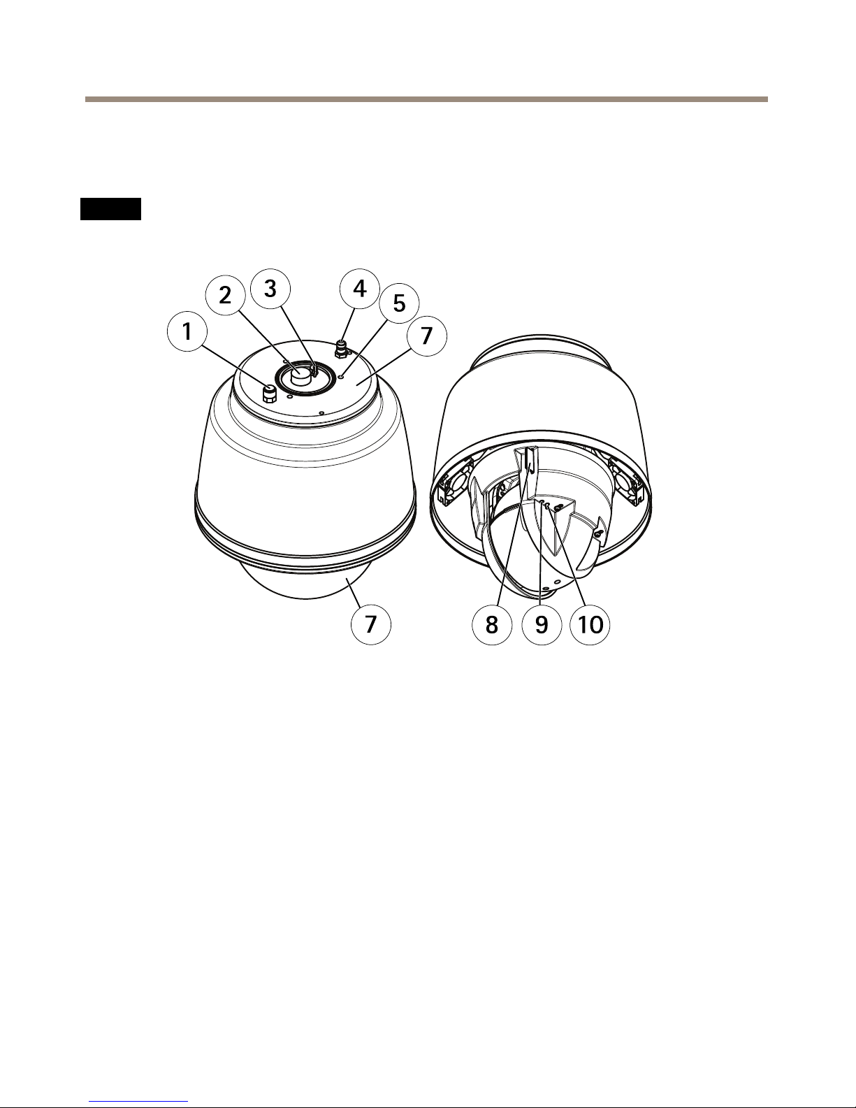
Hardwareoverview
Forspecicationsofthehardwarecomponents,seeTechnicalspecicationsonpage19.
NO NO
NO
TICE TICE
TICE
Makesurethedomeisattachedinoperationmode,otherwisefocusmaybeaffected.
1
Pressurereliefvalve
2
Multiconnector
3
Hookforsafetywire
4
Inletvalve
5
Mountinghole(3x)
6
Partnumber(P/N)&Serialnumber(S/N)
7
Dome
8
SDcardslot(SDHC)
9
StatusLEDindicator
10
Controlbutton
4
Page 5
AXISQ6055-SPTZDomeNetworkCamera
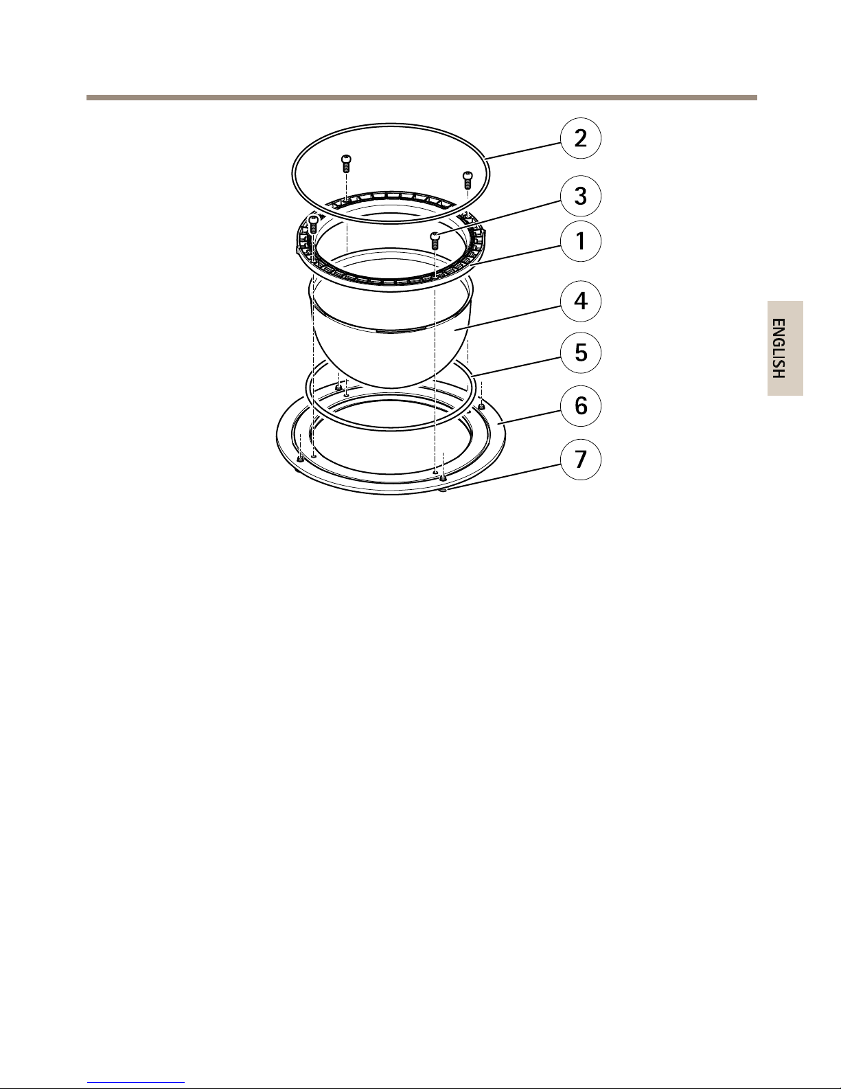
1
Domeattachmentring
2
O-ring
3
DomebracketscrewT20(4x)
4
Dome
5
O-ring
6
Domering
7
DomeringscrewT25(4x)
5
Page 6
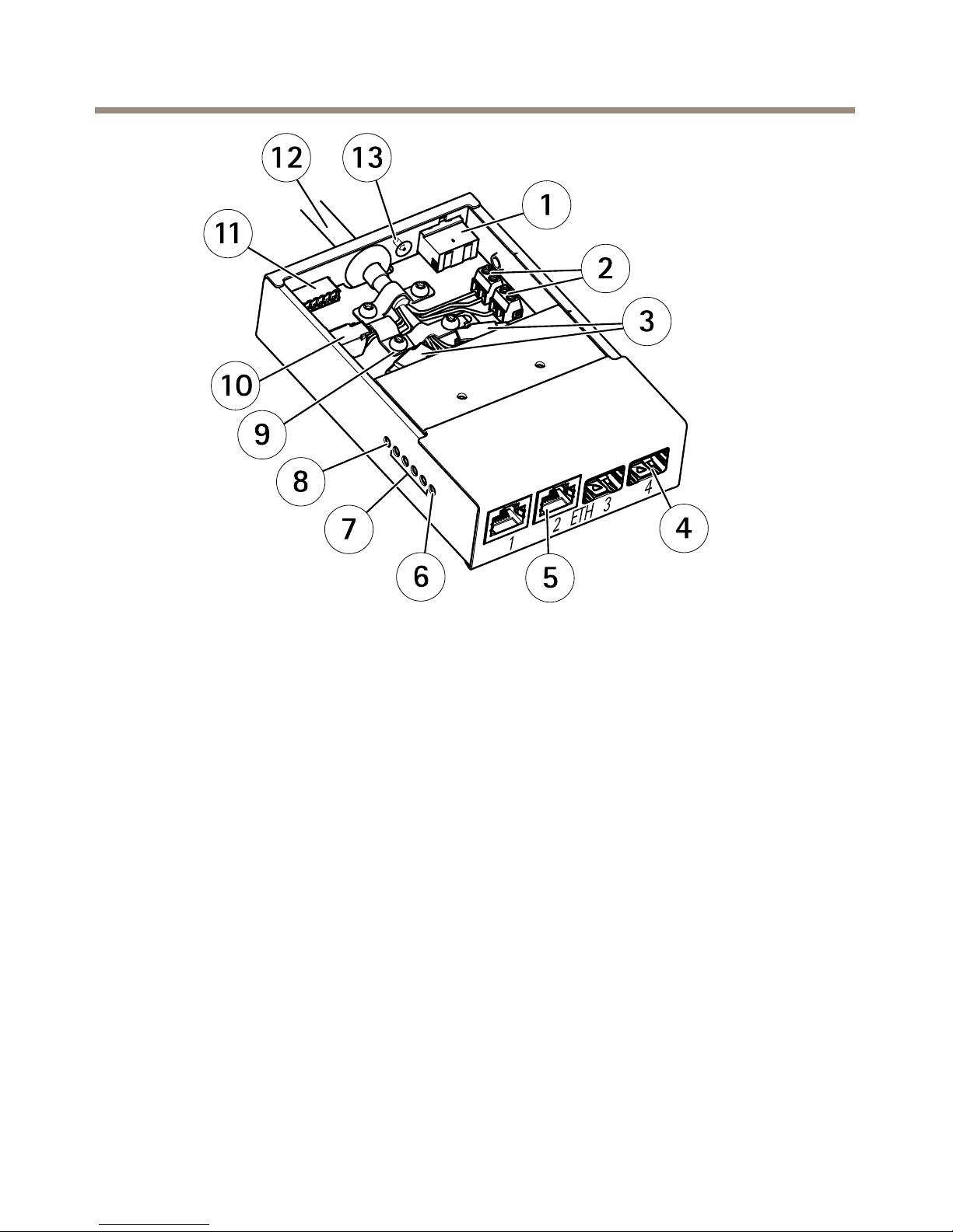
AXISQ6055-SPTZDomeNetworkCamera
1
Powerconnector(DCinput)
2
Powerconnector(DCoutput)
3
Networkconnector(internal)
4
NetworkconnectorSFP(external)(2x)
5
NetworkconnectorRJ45(external)(2x)
6
CameranetworkLEDindicator
7
NetworkLEDindicator(4x)
8
PowerLEDindicator
9
Groundclip
10
I/Oconnector(internal)
11
I/Oconnector(external)
12
Multicable
13
Groundscrew
6
Page 7

AXISQ6055-SPTZDomeNetworkCamera
Howtoinstalltheproduct
Readalltheinstructionsbeforeinstallingtheproduct.Someinstallationstepswouldbenetfrom
beingcompletedtogetherbecausetheyrequireremovalofthedomecover.
NO NO
NO
TICE TICE
TICE
•Duetolocalregulationsortheenvironmentalandelectricalconditionsinwhichthe
productistobeused,ashieldednetworkcable(STP)maybeappropriateorrequired.
Allcablesconnectingtheproducttothenetworkandthatareroutedoutdoorsorin
demandingelectricalenvironmentsshallbeintendedfortheirspecicuse.Makesurethat
thenetworkdevicesareinstalledinaccordancewiththemanufacturer’sinstructions.For
informationaboutregulatoryrequirements,seeRegulatoryinformationonpage32.
•Mounttheproductwiththedomecoverfacingdownward.
•Becarefulnottoscratch,damageorleavengerprintsonthedomecoverbecausethis
coulddecreaseimagequality.Ifpossible,keeptheprotectiveplasticonthedomecover
untiltheinstallationiscomplete.
Theproductcanbemountedwiththecablesroutedthroughoralongthewallorroof.
Recommendedtools
NO NO
NO
TICE TICE
TICE
Stainlesssteeliscorrosion-resistant,butextraneousrustcanappearifthematerialis
handledincorrectly.Usestainlesstoolstoavoidruststainsorpittingcorrosion.
•Torx®screwdriverT10(lid,cableclamping,mediaconverterswitch)
•Cableshoepliers(groundcable,mediaconverterswitch)
•7mmwrench(groundscrew,mediaconverterswitch)
•Slottedscrewdriver2.5mm(socket,mediaconverterswitch)
•Torx®screwdriverT20(domecoverremoval)
•Torx®screwdriverT25(domereplacement)
•8mm(5/16”)wrench/socket(hoseclamp,AXIST91C67PoleBracket)
•10mm(3/8”)wrench/socket(bracketadapterAXIST91C61,AXIST94S01D,AXIST91C67
PoleBracket)
•Diagonalpliers(cables)
•Wirestrippingtool(cableconnecting)
7
Page 8

AXISQ6055-SPTZDomeNetworkCamera
Howtoreplacethedomecover(optional)
Thepremountedcleardomecovercanbereplacedifyouwanttouseasmokeddomecoverorifthe
domecoverisscratchedordamaged.Smokeddomecoversandsparecleardomecoverscanbe
purchasedfromyourAxisreseller.
UsetheInstallationGuidedeliveredwiththedomecover.
HowtoinstallanSDcard
InstallinganSDcardisoptional.AstandardorhighcapacitySDcard(notincluded)canbeusedto
storerecordingslocallyintheproduct.
1.Loosenthedomeringscrewsandremovethedomecover.
2.InsertanSDcardintotheSDcardslot.
3.Attachthedomecovertothetopcoverandtightenthescrews(torque3.2Nm).
Howtopressurizethecamera(recommended)
ThecamerahousingcanbelledwithNitrogengastopreventcondensation.
Thellingprocessisrepeatedthreetimes,releasingthepressurebetweenllings,tomakesurethat
allairandhumidityispurgedfromthehousing.
Note
Thecamerahousinghasanpressurereliefvalvethatlimitsthellingpressureto0.5bar
(7psi).Duringnormalusethepressureinsidethecamerahousingmaydropbelowthat
pressure.Forfullprotectionmakesurethatthepressureisabove0.2bar(3psi).
1.Settheregulatorgaugeonthegascylinderto0.5bar(7psi).
2.Removethecapsfromtheinletvalveandthepressurereliefvalve.
3.Placethechuckontheinletvalveandpressdowntollthecamerawithnitrogen.
4.Whenthepressureinsidethecamerahousingreaches0.5bar(7psi)thepressurerelief
valvewillopen.Placeyourhandoverthepressurereliefvalvetoverifythatthegas
isowingout.
5.Liftthepressurereliefvalvetolettheoverpressureoutofthecameraunit.
6.Repeatthellingprocessatotalof3times,leavingthethecamerapressurizedthe
lasttime.
7.Putthecapsbackontheinletvalveandthepressurereliefvalve.
8
Page 9
AXISQ6055-SPTZDomeNetworkCamera
HowtoinstallAXIST8607MediaConverterSwitch
Thesuppliedmediaconverterswitchenablesthemulticabletosendpowerfromthepowersupply
(soldseparately)andtosendandreceivedatatoandfromexternalalarmdevicesandthenetwork.
NO NO
NO
TICE TICE
TICE
•Makesuretheconnectionstothemainssupplyandconduitshavebeeninstalledbya
trainedprofessional,accordingtothemanufacturer’sinstructionsandincompliance
withlocalregulations.
•Thepowersupply(soldseparately)andthemediaconverterswitchshallbeinstalledinan
environmentprotectedagainstdustandwater,forexampleindoorsorinanappropriate
cabinet.
Important
Axiscanonlyguaranteefullfunctionalitywiththesuppliedmediaconverterswitch.No
otherdevicesaresupported.
1.Makesurethemainssupplyisswitchedoff.
2.Mountthepowersupplyandthemediaconverterswitchonthewallor,ifapplicable,
attachthemtoaDINrailinthecabinet.Ifdrillingisrequired,makesuretousedrillbits,
screws,andplugsthatareappropriateforthematerial.
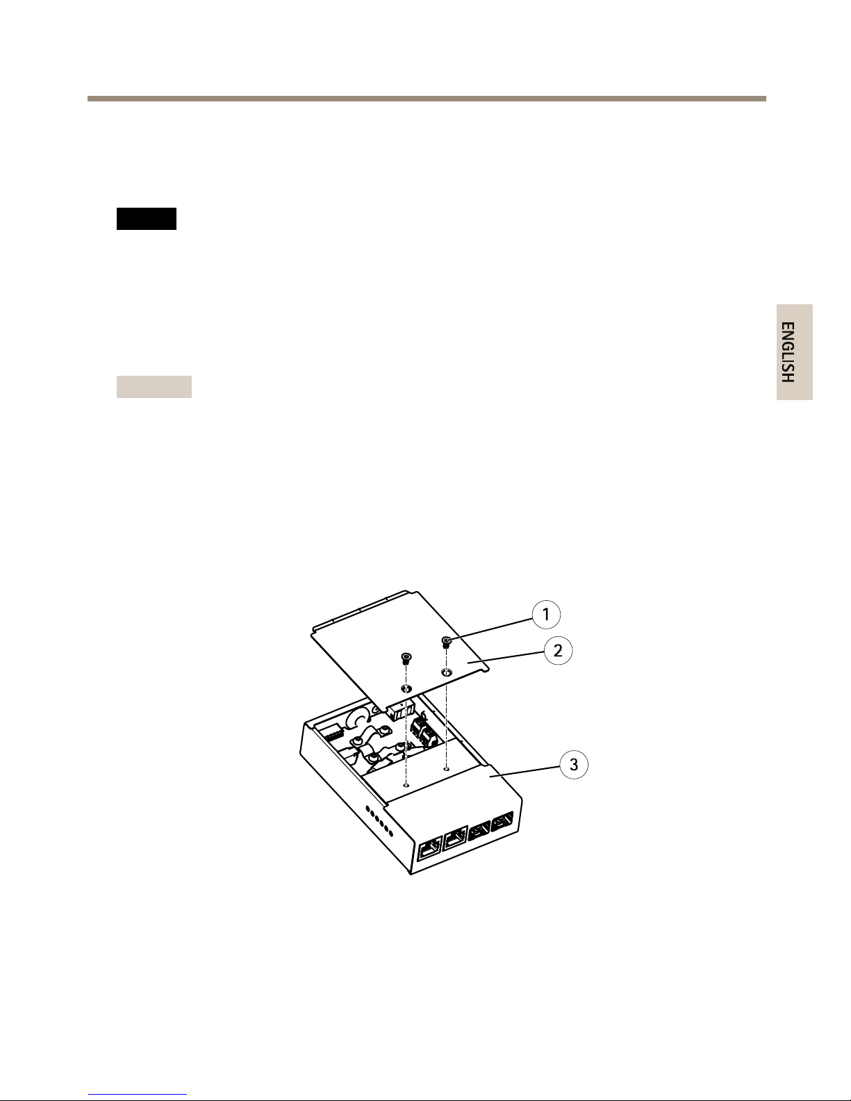
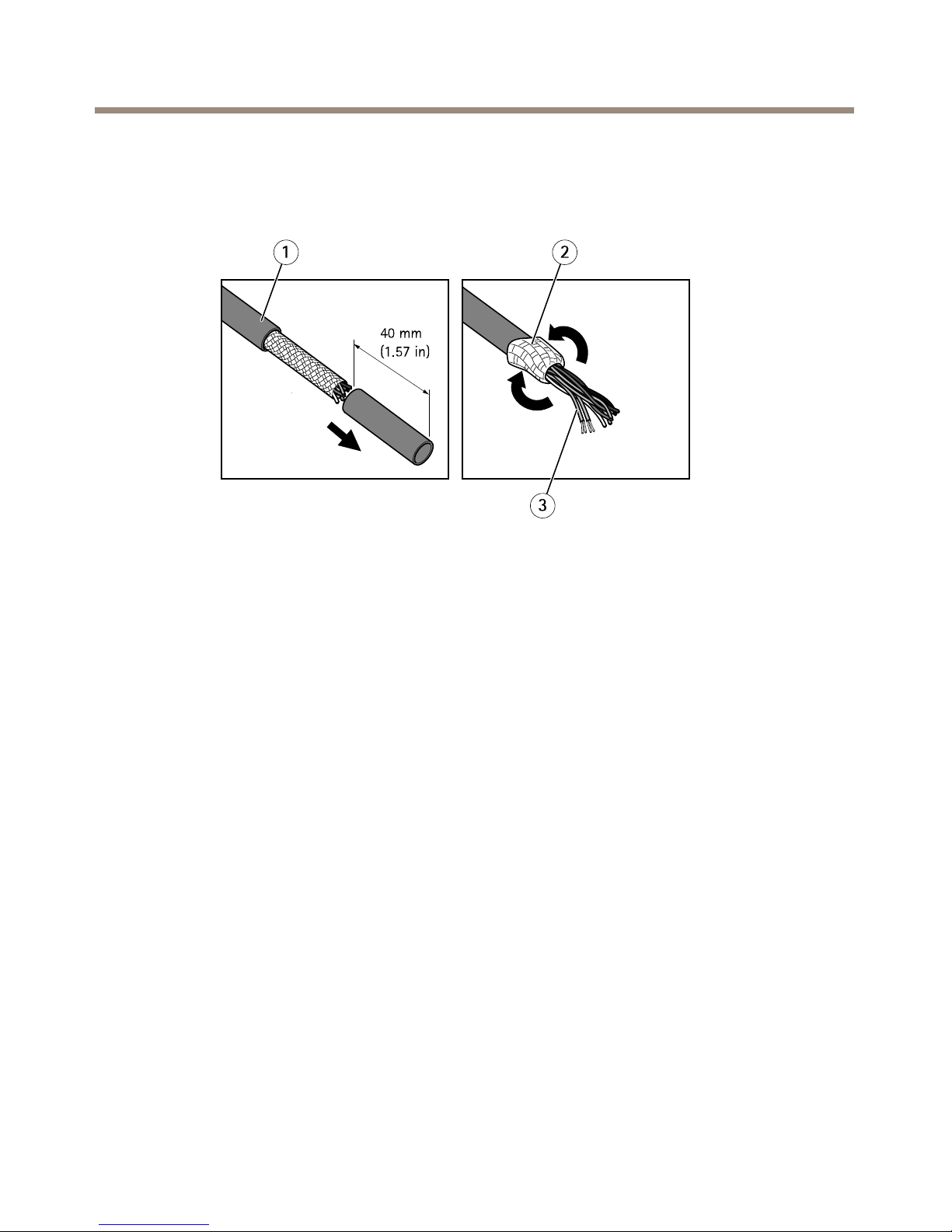
3.Loosenthescrewsandremovethecoverfromthemediaconverterswitch.
1
Screw(2x)
2
Cover
3
Mediaconverterswitch
4.Stripoff40mm(1.57in)ofthemulticablejacket.
9
Page 10
AXISQ6055-SPTZDomeNetworkCamera
5.Leavethebraidedshieldintactandfoldbackthebraidedshield.
6.Cutoffabout7–8mm(0.27–0.32in)oftheEthernetwirefoilshields.
7.Stripoffabout4–5mm(0.16–0.20in)ofthepowerwirejackets.
1
Multicablejacket
2
Braidedshield
3
Ethernetwirefoilshield(2x)
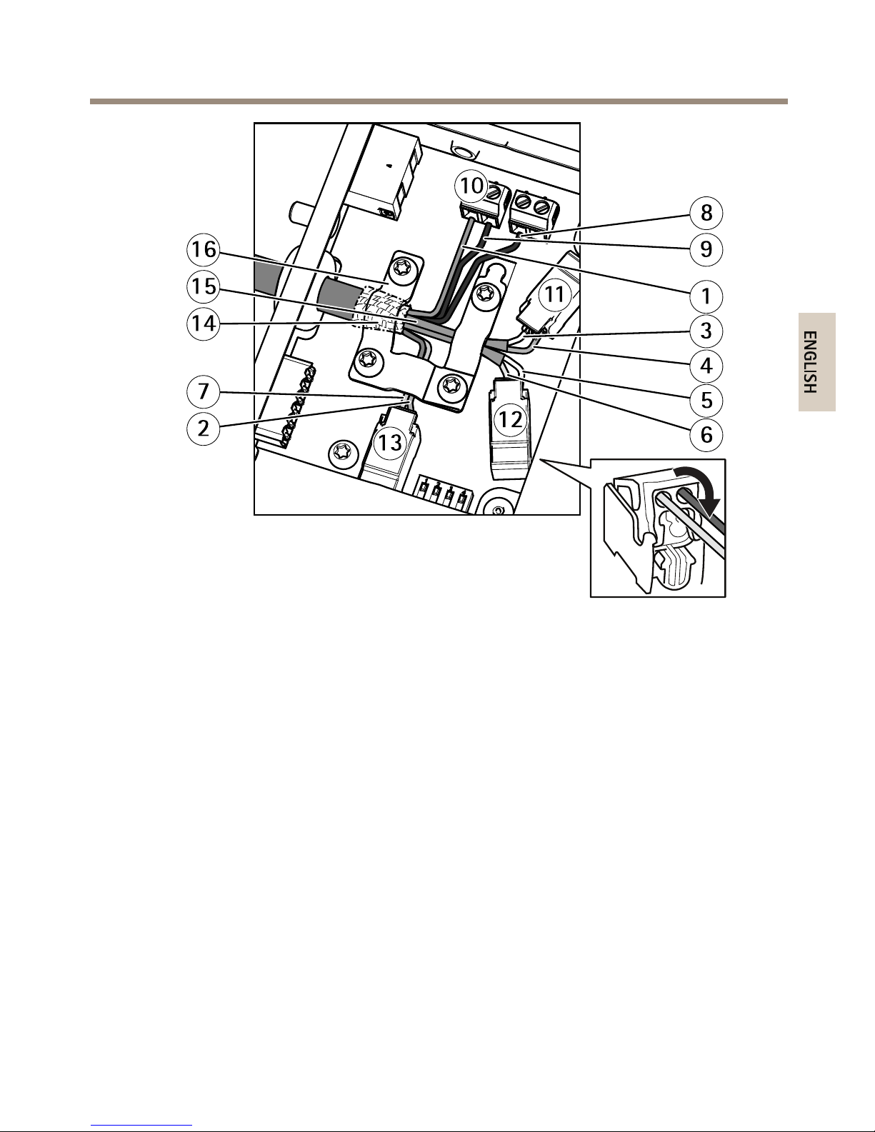
8.ConnectthenetworkandI/OwirestotheinternalnetworkandI/Oconnectors.Open
thelid,insertthewiresandclose.
9.Connectthegroundandpowerwirestothepowerconnector(DCoutput).
10
Page 11
AXISQ6055-SPTZDomeNetworkCamera
1
Powerwire(red)
2
DigitalI/Owire(blue)
3
Ethernetwire(green/white)
4
Ethernetwire(green)
5
Ethernetwire(orange/white)
6
Ethernetwire(orange)
7
DigitalI/Owire(yellow)
8
Groundwire(black)
9
Powerwire(red)
10
Powerconnector(DCoutput)
11
Ethernetconnector(internal)
12
Ethernetconnector(internal)
13
I/Oconnector(internal)
14
Braidedshieldcoil
15
Ethernetwireshield(2x)
16
Clamp
10.Makesuretheclampisinplace,insertthebraidedshieldcoilintothegroundclipand
tightenthescrews.
11
Page 12

AXISQ6055-SPTZDomeNetworkCamera
NO NO
NO
TICE TICE
TICE
•Theshieldsandtheclampsurfacesshallbeinfullcontactwitheachothersothatthe
multicableisgrounded.
•Makesurethatthemulticablejacketisrmlysecuredbytheclamp.
•Makesureallsurfacesandcontactsarecleanandfreefromscrapshieldmaterial.
11.Connectthenetworkcablestotheexternalnetworkconnectors(RJ45,SFP)asrequired.
Note
AnSFPmodule(notincluded)hastobeusedwhenconnectinganopticalbercable.
1
Powercable(DCinput)
2
Powerconnector(DCinput)
3
NetworkconnectorSFP(external)(2x)
4
NetworkconnectorRJ45(external)(2x)
5
I/Oconnector(external)
6
MulticableIP66
7
Groundwire
8
Groundscrew
12
Page 13

AXISQ6055-SPTZDomeNetworkCamera
12.Ifapplicable,connectanI/OdevicetotheexternalI/Oconnector.
13.Connectthepowercable(DCinput)tothepowerconnector(DCinput)viatheterminal
blockplug.
14.Attachthegroundwiretothegroundscrew.
15.Ifconnectingseveralmediaconverterswitchesinadaisychain,setthedipswitchof
eachoutgoingnetworkconnectorportthatconnectstoanothermediaconverterswitch
topositionC.
Leavethedipswitchinitsdefaultposition(positionB)whenconnectingtheportdirectly
tothenetwork.Formoreinformation,seeMediaconverterswitchconnectorsonpage22.
Important
Ifthesystemisnotdened,usethedefaultdipswitchsetting(positionB).
1
Dipswitch(4x)
16.Attachthecovertothemediaconverterswitch.
17.Switchonthemainssupply.
18.MakesuretheLEDindicatorsonthemediaconverterswitchindicatethecorrect
conditions.Formoreinformation,seeMediaconverterswitchLEDindicatorsonpage19.
13
Page 14

AXISQ6055-SPTZDomeNetworkCamera
1
PowerLEDindicator
2
NetworkLEDindicator(4x)ETH1/2/3/4
3
CameraLEDindicator
Howtoinstallthecamera
NO NO
NO
TICE TICE
TICE
TocomplywiththeIP66-rateddesignofthecameraandmaintaintheIP66protection,the
suppliedmulticableshallbeused.
1.Installtheselectedbracketaccordingtotheinstructionssuppliedwiththebracket.If
drillingisrequired,makesuretousedrillbits,screws,andplugsthatareappropriatefor
thematerial.
2.Routethemulticablethroughtheholesinthemountingbracket.
3.Securethecamerausingthesuppliedsafetywire.
14
Page 15

AXISQ6055-SPTZDomeNetworkCamera
Mountingexample(wallbracketsoldseparately)
1
Safetywire
4.Removetheprotectioncapcoveringthemulticonnectoronthecamera.
5.Connectthemulticabletotheconnectoronthecamera.Usethealignmentindicatorsto
ndthecorrectposition.
NO NO
NO
TICE TICE
TICE
Becarefulnotdodamagethemulticablewhenconnectingit.
6.Fastenthenetworkcameratothemountingbracketwiththescrews.
15
Page 16

AXISQ6055-SPTZDomeNetworkCamera
Mountingexample(wallbracketsoldseparately)
1
Alignmentindicator–multicable
2
Alignmentindicator–camera
3
Flange
4
Multicable
Howtoaccesstheproduct
AXISIPUtilityandAXISCameraManagementarerecommendedmethodsforndingAxisproducts
onthenetworkandassigningthemIPaddressesinWindows®.Bothapplicationsarefreeandcan
bedownloadedfromwww.axis.com/support
Theproductcanbeusedwithmostoperatingsystemsandbrowsers.Werecommendthefollowing
browsers:
•InternetExplorer
®
withWindows
®
•Safari
®
withOSX
®
•Chrome
TM
orFirefox
®
withotheroperatingsystems.
Formoreinformationaboutusingtheproduct,seetheUserManualavailableatwww.axis.com
16
Page 17

AXISQ6055-SPTZDomeNetworkCamera
Howtoresettofactorydefaultsettings
Important
Resettofactorydefaultshouldbeusedwithcaution.Aresettofactorydefaultresetsall
settings,includingtheIPaddress,tothefactorydefaultvalues.
Toresettheproducttothefactorydefaultsettings:
1.Disconnectpowerfromtheproduct.
2.Pressandholdthecontrolbuttonandreconnectpower.
3.Keepthecontrolbuttonpressedfor15–30secondsuntilthestatusLEDindicatorashes
amber.
4.Releasethecontrolbutton.TheprocessiscompletewhenthestatusLEDindicatorturns
green.Theproducthasbeenresettothefactorydefaultsettings.IfnoDHCPserveris
availableonthenetwork,thedefaultIPaddressis192.168.0.90
5.Usingtheinstallationandmanagementsoftwaretools,assignanIPaddress,setthe
password,andaccessthevideostream.
Theinstallationandmanagementsoftwaretoolsareavailablefromthesupportpages
atwww.axis.com/support
Itisalsopossibletoresetparameterstofactorydefaultviathewebinterface.GotoSetup>
SystemOptions>MaintenanceandclickDefault.
17
Page 18

AXISQ6055-SPTZDomeNetworkCamera
Furtherinformation
•Forthelatestversionofthisdocument,seewww.axis.com
•Theusermanualisavailableatwww.axis.com
•Tocheckifthereisupdatedrmwareavailableforyourproduct,see
www.axis.com/support
•Forusefulonlinetrainingsandwebinars,seewww.axis.com/academy
Optionalaccessories
Foracompletelistofavailableaccessoriesforthisproduct,gotowww.axis.com
18
Page 19

AXISQ6055-SPTZDomeNetworkCamera
Technicalspecifications
Youcanndthelatestversionofthedatasheetatwww.axis.com
LEDIndicators
StatusLED
Indication
Unlit
Connectionandnormaloperation.
GreenShowssteadygreenfor10secondsfornormaloperationafter
startupcompleted.
Amber
Steadyduringstartup.Flashesduringrmwareupgradeorreset
tofactorydefault.
Amber/RedFlashesamber/redifnetworkconnectionisunavailableorlost.
RedFirmwareupgradefailure.
MediaconverterswitchLEDindicators
LED
Color
Indication
Unlit
DCpowerunconnectedorcurrentprotectionengaged(power
overload)
Power
GreenDCpowerconnected.
Amber10Mbitconnection.Flashesduringactivity.
Network(4x)
Green
100/1000Mbitconnection.Flashesduringactivity.
Camera
network(only
availableon
AXIST8607)
Green
100Mbitconnection.Flashesduringactivity.
SDcardslot
NO NO
NO
TICE TICE
TICE
•RiskofdamagetoSDcard.Donotusesharptools,metalobjectsorexcessiveforcewhen
insertingorremovingtheSDcard.Useyourngerstoinsertandremovethecard.
•Riskofdatalossandcorruptedrecordings.DonotremovetheSDcardwhiletheproduct
isrunning.DisconnectpowerorunmounttheSDcardfromtheAxisproduct’swebpages
beforeremoval.
19
Page 20

AXISQ6055-SPTZDomeNetworkCamera
ThisproductsupportsSD/SDHC/SDXCcards(notincluded).
ForSDcardrecommendations,seewww.axis.com
Buttons
ControlButton
Forlocationofthecontrolbutton,seeHardwareoverviewonpage4.
Thecontrolbuttonisusedfor:
•Resettingtheproducttofactorydefaultsettings.Seepage17.
•ConnectingtoanAXISVideoHostingSystemserviceorAXISInternetDynamicDNS
Service.Formoreinformationabouttheseservices,seetheUserManual.
Connectors
Multiconnector
Terminalconnectorforconnectingthesuppliedmediaconverterswitch,whichprovidesthe
followingsignals:
•DCPower
•Network(Ethernet10/100Base-T)
•Input/Output(I/O)
Multicableconnectors
Note
Thesuppliedmulticableisrequiredinordertomaintainthecamera’sNEMA/IPrating.
Themulticableisconnectedtothecamera’smulticonnector,seeHardwareoverviewonpage4.
Thewiresareconnectedtothesuppliedmediaconverterswitch,seeAXIST8607MediaConverter
Switchonpage5.
Thecableprovidesthefollowingsignals:
•DCpowertocamera
•Network(Ethernet10/100Base-T)
•Input/Output(I/O)
20
Page 21

AXISQ6055-SPTZDomeNetworkCamera
Multicableoverview
1
Powerwire(red)
2
DigitalI/Owire(blue)
3
Ethernetwire(green/white)
4
Ethernetwire(green)
5
Ethernetwire(orange/white)
6
Ethernetwire(orange)
7
DigitalI/Owire(yellow)
8
Groundwire(black)
9
Powerwire(red)
10
Ethernetwirefoilshield(2x)
11
Braidedshieldcoil
FunctionWire
ConnecttoSpecications
Digitalinput–I/Oterminalconnector
0tomax30VDC Congurable
(Inputor
Output)
2–blue
7–yellow
Digitaloutput–I/Oterminal
connector
0tomax30VDC,
opendrain,
100mA
RX+
3–green/white
Ethernet–receiving
RX-
4–green
Ethernet–receiving
TX+
5–orange/white
Ethernet–transmitting
TX-
6–orange
Ethernet–transmitting
0VDC(-)
8–black
0VDC
DCoutput
(24V)
1,9–redPowerconnector
24VDC
21
Page 22

AXISQ6055-SPTZDomeNetworkCamera
Mediaconverterswitchconnectors
NO NO
NO
TICE TICE
TICE
Theproductshallbeconnectedusingashieldednetworkcable(STP).Allcablesconnecting
theproducttothenetworkshallbeintendedfortheirspecicuse.Makesurethatthe
networkdevicesareinstalledinaccordancewiththemanufacturer’sinstructions.For
informationaboutregulatoryrequirements,seeElectromagneticcompatibility(EMC)on
page32.
Important
Themediaconverterswitchdoesnotsupporthotswapping.Disconnectpowerfromthe
switchbeforeswappingcameras.Anattempttohotswapcouldcausetheswitchtofreeze,
inwhichcaseitmustberestarted.
Cameraconnectors
Powerconnector
Two2-pinterminalblocksforpoweroutput(pin4
isnotused).
FunctionPinNotes
24VDC
1,2
Powerouttocamera
0VDC(-)
3
DC
output
N/A
4
N/A
Networkconnector
Two2-pinEthernetterminalblocks.
22
Page 23

AXISQ6055-SPTZDomeNetworkCamera
I/Oterminalconnector
2-pinterminalblock.
Externalconnectors
GroundscrewGroundscrewforconnectingthemedia
converterswitchtoearthground.Make
surethatbothendsofthegrounding
wireareincontactwiththeirrespective
groundingsurfaces.
Powerconnector
2-pinterminalblockforpowerinput.
FunctionPinNotes
0VDC(-)
1
DCinput
24VDC
2
Powerinfrompower
supply(soldseparately)
NetworkconnectorRJ45
TwoRJ45connectors(10/100Base-T)for
network.
NetworkslotSFP
TwoSFPslots(100Base-FX/1000Base-X)for
network.
EachRJ45andSFPporthasitsowndipswitch.Thedipswitchescontrolhowtheportforwards
data.Formoreinformation,seepage24.
23
Page 24

AXISQ6055-SPTZDomeNetworkCamera
I/Oterminalconnector
6-pincongurableI/Oterminalblock,whichisconnectedtothecamerathroughthemulticable.
Usewithexternaldevicesincombinationwith,forexample,tamperingalarms,motiondetection,
eventtriggering,timelapserecordingandalarmnotications.Inadditiontothe0VDC
referencepointandpower(DCoutput),theI/Oconnectorprovidestheinterfaceto:
•Digitaloutput–ForconnectingexternaldevicessuchasrelaysandLEDs.Connected
devicescanbeactivatedbytheVAPIX®ApplicationProgrammingInterface,output
buttonsontheLiveViewpageorbyanActionRule.Theoutputwillshowasactive
(shownunderSystemOptions>Port&Devices>PortStatus)ifthealarmdevice
isactivated.
•Digitalinput–Analarminputforconnectingdevicesthatcantogglebetween
anopenandclosedcircuit,forexample:PIRs,door/windowcontacts,glassbreak
detectors,etc.Whenasignalisreceivedthestatechangesandtheinputbecomes
active(shownunderSystemOptions>Port&Devices>PortStatus).
6-pinterminalblocksfor:
•DigitalInput/Output
•Power(DCoutput)
•0VDC(-)
FunctionPinNotes
Specications
0VDC(-)
1,4,6
0VDC
DCoutput
2
Powerout
12VDC,50mA
Digitalinput
0tomax30VDC
Congurable
I/O1(InputorOutput)
3
Digitaloutput(transistor–
opencollector)
0tomax30VDC,
opendrain,100mA
Digitalinput
0tomax30VDC
Congurable
I/O2(InputorOutput)
5
Digitaloutput(transistor–
opencollector)
0tomax30VDC,
opendrain,100mA
Networkconnectordipswitches
Important
Alwaysusethedefaultdipswitchsetting(positionB)iftherelationshipbetweendevicesin
thesystemisnotdened.
ThecameraattachesaparticularVLANtagtoallitsforwardedmulticastpackages.Themedia
converterswitchmanageshowthesemulticastpackagesareforwardedbetweencameras,media
converterswitchesandothernetworkdevices.Thisisespeciallyusefulwhenconnectingthecamera
andmediaconverterswitchtothenetworkinadaisychain.
24
Page 25

AXISQ6055-SPTZDomeNetworkCamera
Bychangingthepositionofthedipswitches,eachnetworkconnectorportinthemediaconverter
switchcanbeconguredtomanagemulticastsinthreedifferentways.
Dipswitch
position
Description
Default
(middle)
BRemoveVLANtagsfromforwardedmulticastpackages.Usethissetting
whenconnectingtothenetwork,directlyorthrougharouterornetwork
switch.
LeftABlockmulticastpackagesthathaveaVLANtag.Usethissettingwhen
connectingtoadevicethatisnotintendedformulticastviewing.
Right
C
ForwardmulticastpackageswithaVLANtag.Usethissettingwhen
connectingtoanothermediaconverterswitch.
VLANtagsareusedtocreateindependentlogicalnetworks,virtuallocalareanetworks(VLANs),
withinaphysicalnetwork.Multiplemediaconverterswitchesthatareconnectedtoeachother
inadaisychainaremembersofthesameVLAN.Themediaconverterswitchestagthemulticast
packagesmovingbetweenthemsothatthenextmediaconverterswitchinlineknowsthe
destinationofthepackages.Inotherwords,theVLANtagservesasaVLANidentier.VLAN
taggingshouldonlybeusedwhenusingmultiplecamerasandmediaconverterswitchesbecause
forwardingmulticastpackageswithaVLANtagonlyservesapurposewhentheportisconnected
toanothermediaconverterswitch,whichmightbeconnectedtopotentialviewers.
Note
Whenconnectinganoutgoingmediaconverterswitchnetworkconnectortoanothertypeof
networkdevice,setthedipswitchtopositionAtoprotectthedevicefrommulticasttrafc.
25
Page 26

AXISQ6055-SPTZDomeNetworkCamera
Operatingconditions
TheAxisproductisintendedforoutdooruse.
ClassicationIEC60721-4-3
Class3K3
IEC/EN60529IP66
ISO20653IP6K9K
Temperature
-30°Cto50°C
(-22°Fto122°F)
Humidity
10–100%RH(condensing)
Storageconditions
Temperature
-40°Cto65°C
(-40°Fto149°F)
Electricalspecications
NO NO
NO
TICE TICE
TICE
ForconrmedcompliancewiththerequirementsforSafetyExtraLowVoltage(SELV)and
LimitedPowerSource(LPS),usethepowersupply(soldseparately)recommendedbyAxis.
Forinformationaboutcompatiblepoweraccessories,seewww.axis.com
ProductFunctionDescription
NetworkcameraInputpower
24VDC,min65W
Inputvoltage
24VDC
Inputpowermin75W
Availableoutputpowermin70W
Nominaloutputvoltage
24VDC
Mediaconverterswitch
Minimuminputcurrent3.2A
26
Page 27

AXISQ6055-SPTZDomeNetworkCamera
1
Mediaconverterswitch
2
Multicable
3
Networkcamera
27
Page 28

28
Page 29

AXISQ6055-SPTZDomeNetworkCamera
Safetyinformation
Hazardlevels
DANGER
Indicatesahazardoussituationwhich,ifnotavoided,willresultindeathorseriousinjury.
WARNING
Indicatesahazardoussituationwhich,ifnotavoided,couldresultindeathorseriousinjury.
CAUTION
Indicatesahazardoussituationwhich,ifnotavoided,couldresultinminorormoderate
injury.
NO NO
NO
TICE TICE
TICE
Indicatesasituationwhich,ifnotavoided,couldresultindamagetoproperty.
Othermessagelevels
Important
Indicatessignicantinformationwhichisessentialfortheproducttofunctioncorrectly.
Note
Indicatesusefulinformationwhichhelpsingettingthemostoutoftheproduct.
29
Page 30

AXISQ6055-SPTZDomeNetworkCamera
Safetyinstructions
WARNING
TheAxisproductshallbeinstalledbyatrainedprofessional,andincompliancewithlocal
lawsandregulations.
NO NO
NO
TICE TICE
TICE
•TheAxisproductshallbeusedincompliancewithlocallawsandregulations.
•StoretheAxisproductinadryandventilatedenvironment.
•AvoidexposingtheAxisproducttoshocksorheavypressure.
•Donotinstalltheproductonunstablepoles,brackets,surfacesorwalls.
•UseonlyapplicabletoolswheninstallingtheAxisproduct.Usingexcessiveforcewith
powertoolscouldcausedamagetotheproduct.
•Donotusechemicals,causticagents,oraerosolcleaners.
•Useacleanclothdampenedwithpurewaterforcleaning.
•Useonlyaccessoriesthatcomplywiththetechnicalspecicationofyourproduct.These
canbeprovidedbyAxisorathirdparty.AxisrecommendsusingAxispowersource
equipmentcompatiblewithyourproduct.
•UseonlysparepartsprovidedbyorrecommendedbyAxis.
•Donotattempttorepairtheproductyourself.ContactAxissupportoryourAxisreseller
forservicematters.
•Donotpointthecameralenstowardthesunorotherhigh-intensityradiationsources
becausethiscouldcausedamagetothecamera.
Transportation
NO NO
NO
TICE TICE
TICE
•Keeptheprotectivepackaging.WhentransportingtheAxisproduct,theprotective
packagingshallbereplacedinitsoriginalposition.
•WhentransportingtheAxisproduct,usetheoriginalpackagingorequivalenttoprevent
damagetotheproduct.
Battery
TheAxisproductusesa3.0VBR2032lithiumbatteryasthepowersupplyforitsinternalreal-time
clock(RTC).Undernormalconditionsthisbatterywilllastforaminimumofveyears.
30
Page 31

AXISQ6055-SPTZDomeNetworkCamera
LowbatterypoweraffectstheoperationoftheRTC,causingittoresetateverypower-up.When
thebatteryneedsreplacing,alogmessagewillappearintheproduct’sserverreport.Formore
informationabouttheserverreport,seetheproduct´ssetuppagesorcontactAxissupport.
Thebatteryshouldnotbereplacedunlessrequired,butifthebatterydoesneedreplacing,contact
Axissupportatwww.axis.com/supportforassistance.
Lithiumcoincell3.0Vbatteriescontain1,2-dimethoxyethane;ethyleneglycoldimethylether
(EGDME),CASno.110-71-4.
WARNING
•Riskofexplosionifthebatteryisincorrectlyreplaced.
•ReplaceonlywithanidenticalbatteryorabatterywhichisrecommendedbyAxis.
•Disposeofusedbatteriesaccordingtolocalregulationsorthebatterymanufacturer's
instructions.
DomeCover
NO NO
NO
TICE TICE
TICE
•Becarefulnottoscratch,damageorleavengerprintsonthedomecoverbecausethis
coulddecreaseimagequality.Ifpossible,keeptheprotectiveplasticonthedomecover
untiltheinstallationiscomplete.
•Donotcleanadomecoverthatlookscleantotheeyeandneverpolishthesurface.
Excessivecleaningcoulddamagethesurface.
•Forgeneralcleaningofthedomecoveritisrecommendedtouseanon-abrasive,
solvent-freeneutralsoapordetergentmixedwithpurewaterandasoft,cleancloth.Rinse
wellwithpurelukewarmwater.Drywithasoft,cleanclothtopreventwaterspotting.
•Neveruseharshdetergentsoralcohols(isopropyl,butyl,propyl)andavoidcleaningthe
domecoverindirectsunlightoratelevatedtemperatures.
31
Page 32

Legalconsiderations
Videosurveillancecanberegulatedbylawsthatvaryfrom
countrytocountry.Checkthelawsinyourlocalregion
beforeusingthisproductforsurveillancepurposes.
Thisproductincludesthefollowinglicences:
•one(1)H.264decoderlicense
Topurchasefurtherlicenses,contactyourreseller.
Liability
Everycarehasbeentakeninthepreparationofthis
document.PleaseinformyourlocalAxisofceofany
inaccuraciesoromissions.AxisCommunicationsABcannot
beheldresponsibleforanytechnicalortypographicalerrors
andreservestherighttomakechangestotheproductand
manualswithoutpriornotice.AxisCommunicationsAB
makesnowarrantyofanykindwithregardtothematerial
containedwithinthisdocument,including,butnotlimited
to,theimpliedwarrantiesofmerchantabilityandtnessfor
aparticularpurpose.AxisCommunicationsABshallnot
beliablenorresponsibleforincidentalorconsequential
damagesinconnectionwiththefurnishing,performance
oruseofthismaterial.Thisproductisonlytobeusedfor
itsintendedpurpose.
Intellectualpropertyrights
AxisABhasintellectualpropertyrightsrelatingto
technologyembodiedintheproductdescribedinthis
document.Inparticular,andwithoutlimitation,these
intellectualpropertyrightsmayincludeoneormoreof
thepatentslistedatwww.axis.com/patent.htmandoneor
moreadditionalpatentsorpendingpatentapplicationsin
theUSandothercountries.
Thisproductcontainslicensedthird-partysoftware.See
themenuitem“About”intheproduct’suserinterfacefor
moreinformation.
ThisproductcontainssourcecodecopyrightAppleComputer,
Inc.,underthetermsofApplePublicSourceLicense2.0
(seewww.opensource.apple.com/apsl).Thesourcecodeis
availablefromhttps://developer.apple.com/bonjour/
Equipmentmodications
Thisequipmentmustbeinstalledandusedin
strictaccordancewiththeinstructionsgiveninthe
userdocumentation.Thisequipmentcontainsno
user-serviceablecomponents.Unauthorizedequipment
changesormodicationswillinvalidateallapplicable
regulatorycerticationsandapprovals.
Trademarkacknowledgments
AXISCOMMUNICATIONS,AXISandVAPIXareregistered
trademarksortrademarkapplicationsofAxisABinvarious
jurisdictions.Allothercompanynamesandproductsare
trademarksorregisteredtrademarksoftheirrespective
companies.
Apple,Boa,Apache,Bonjour,Ethernet,InternetExplorer,
Linux,Microsoft,Mozilla,Real,SMPTE,QuickTime,UNIX,
Windows,WindowsVistaandWWWareregistered
trademarksoftherespectiveholders.Javaandall
Java-basedtrademarksandlogosaretrademarksor
registeredtrademarksofOracleand/oritsafliates.
UPnP
TM
isacerticationmarkoftheUPnP
TM
Implementers
Corporation.
SD,SDHCandSDXCaretrademarksorregisteredtrademarks
ofSD-3C,LLCintheUnitedStates,othercountriesorboth.
Also,miniSD,microSD,miniSDHC,microSDHC,microSDXC
arealltrademarksorregisteredtrademarksofSD-3C,LLC
intheUnitedStates,othercountriesorboth.
Regulatoryinformation
Europe
ThisproductcomplieswiththeapplicableCEmarking
directivesandharmonizedstandards:
•ElectromagneticCompatibility(EMC)Directive
2014/30/EU.SeeElectromagneticcompatibility(EMC)
onpage32.
•LowVoltage(LVD)Directive2014/35/EU.SeeSafety
onpage33.
•RestrictionsofHazardousSubstances(RoHS)Directive
201 1/65/EU.SeeDisposalandrecyclingonpage33.
Acopyoftheoriginaldeclarationofconformitymaybe
obtainedfromAxisCommunicationsAB.SeeContact
informationonpage33.
Electromagneticcompatibility(EMC)
Thisequipmenthasbeendesignedandtestedtofulll
applicablestandardsfor:
•Radiofrequencyemissionwheninstalledaccordingto
theinstructionsandusedinitsintendedenvironment.
•Immunitytoelectricalandelectromagneticphenomena
wheninstalledaccordingtotheinstructionsandused
initsintendedenvironment.
USA
Thisequipmenthasbeentestedusingashieldednetwork
cable(STP)andfoundtocomplywiththelimitsfora
ClassAdigitaldevice,pursuanttopart15oftheFCCRules.
Theselimitsaredesignedtoprovidereasonableprotection
againstharmfulinterferencewhentheequipmentis
operatedinacommercialenvironment.Thisequipment
generates,uses,andcanradiateradiofrequencyenergy
and,ifnotinstalledandusedinaccordancewiththe
instructionmanual,maycauseharmfulinterferenceto
radiocommunications.Operationofthisequipmentin
aresidentialareaislikelytocauseharmfulinterference
inwhichcasetheuserwillberequiredtocorrectthe
interferenceathisownexpense.Theproductshallbe
connectedusingashieldednetworkcable(STP)thatis
properlygrounded.
Canada
ThisdigitalapparatuscomplieswithCANICES-3(ClassA).
Theproductshallbeconnectedusingashieldednetwork
cable(STP)thatisproperlygrounded.Cetappareil
numériqueestconformeàlanormeNMBICES-3(classeA).
Leproduitdoitêtreconnectéàl'aided'uncâbleréseau
blindé(STP)quiestcorrectementmisàlaterre.
Europe
ThisdigitalequipmentfulllstherequirementsforRF
emissionaccordingtotheClassAlimitofEN55032.The
productshallbeconnectedusingashieldednetworkcable
(STP)thatisproperlygrounded.Notice!ThisisaClassA
product.Inadomesticenvironmentthisproductmaycause
RFinterference,inwhichcasetheusermayberequired
totakeadequatemeasures.
Thisproductfulllstherequirementsforemissionand
immunityaccordingtoEN50121-4andIEC62236-4railway
applications.
Thisproductfulllstherequirementsforimmunity
accordingtoEN61000-6-1residential,commercialand
light-industrialenvironments.
Thisproductfulllstherequirementsforimmunity
accordingtoEN61000-6-2industrialenvironments.
Thisproductfulllstherequirementsforimmunity
accordingtoEN55024ofceandcommercial
environments.
Page 33

Australia/NewZealand
ThisdigitalequipmentfulllstherequirementsforRF
emissionaccordingtotheClassAlimitofAS/NZSCISPR32.
Theproductshallbeconnectedusingashieldednetwork
cable(STP)thatisproperlygrounded.Notice!Thisisa
ClassAproduct.Inadomesticenvironmentthisproduct
maycauseRFinterference,inwhichcasetheusermaybe
requiredtotakeadequatemeasures.
Japan
この装置は、クラスA情報技術装置です。この装
置を家庭環境で使⽤すると電波妨害を引き起こす
ことがあります。この場合には使⽤者が適切な対
策を講ずるよう要求されることがあります。本
製品は、シールドネットワークケーブル(STP)を
使⽤して接続してください。また適切に接地し
てください。
Korea
이기기는업무용(A급)전자파적합기기로서판매
자또는사용자는이점을주의하시기바라며,가
정외의지역에서사용하는것을목적으로합니다.
적절히접지된STP(shieldedtwistedpair)케이블
을사용하여제품을연결하십시오.
Safety
ThisproductcomplieswithIEC/EN/UL60950-1and
IEC/EN/UL60950-22,SafetyofInformationTechnology
Equipment.Theproductshallbegroundedeitherthrougha
shieldednetworkcable(STP)orotherappropriatemethod.
Thepowersupplyusedwiththisproductshallfulllthe
requirementsforSafetyExtraLowVoltage(SELV)according
toIEC/EN/UL60950-1.
ThepowersupplyshallbespeciedasaLimitedPower
Source(LPS)accordingtoclause2.5ofIEC/UL60950-1
orCEC/NECClass2sourceofsupplyasdenedinthe
CanadianElectricalCode,CSAC22.1andNationalElectrical
Code,ANSI/NFPA70.
Disposalandrecycling
Whenthisproducthasreachedtheendofitsusefullife,
disposeofitaccordingtolocallawsandregulations.For
informationaboutyournearestdesignatedcollectionpoint,
contactyourlocalauthorityresponsibleforwastedisposal.
Inaccordancewithlocallegislation,penaltiesmaybe
applicableforincorrectdisposalofthiswaste.
Europe
Thissymbolmeansthattheproductshallnotbe
disposedoftogetherwithhouseholdorcommercialwaste.
Directive2012/19/EUonwasteelectricalandelectronic
equipment(WEEE)isapplicableintheEuropeanUnion
memberstates.Topreventpotentialharmtohumanhealth
andtheenvironment,theproductmustbedisposedofin
anapprovedandenvironmentallysaferecyclingprocess.
Forinformationaboutyournearestdesignatedcollection
point,contactyourlocalauthorityresponsibleforwaste
disposal.Businessesshouldcontacttheproductsupplierfor
informationabouthowtodisposeofthisproductcorrectly.
Thisproductcomplieswiththerequirementsof
Directive201 1/65/EUontherestrictionoftheuseof
certainhazardoussubstancesinelectricalandelectronic
equipment(RoHS).
China
Thisproductcomplieswiththerequirementsof
SJ/T1 1364-2014,Markingfortherestrictionofhazardous
substancesinelectricalandelectronicproducts.
有毒有害物质或元素
部
件
名
称
铅
(Pb)
汞
(Hg)
镉
(Cd)
六价
铬
(Cr(VI))
多溴
联苯
(PBB)
多溴
二苯
醚
(PBDE)
电
气
实
装
部
分
X
00000
0:表示该有毒有害物质在该部件所有均质材料中
的含量均在GB/T26572标准规定的限量要求以下。
X:表示该有毒有害物质至少在该部件的某一均质
材料中的含量超出GB/T26572标准规定的限量要
求。
Contactinformation
AxisCommunicationsAB
Emdalavägen14
22369Lund
Sweden
Tel:+46462721800
Fax:+4646136130
www.axis.com
Warrantyinformation
ForinformationaboutAxis’productwarrantyandthereto
relatedinformation,gotowww.axis.com/warranty/
Support
Shouldyourequireanytechnicalassistance,pleasecontact
yourAxisreseller.Ifyourquestionscannotbeanswered
immediately,yourresellerwillforwardyourqueriesthrough
theappropriatechannelstoensurearapidresponse.Ifyou
areconnectedtotheInternet,youcan:
•downloaduserdocumentationandsoftwareupdates
•ndanswerstoresolvedproblemsintheFAQdatabase.
Searchbyproduct,category,orphrase
•reportproblemstoAxissupportstaffbylogginginto
yourprivatesupportarea
•chatwithAxissupportstaff
•visitAxisSupportatwww.axis.com/support
Learnmore!
VisitAxislearningcenterwww.axis.com/academy/for
usefultrainings,webinars,tutorialsandguides.
Page 34

InstallationGuide
Ver.M3.3
AXISQ6055-SPTZDomeNetworkCamera
Date:March2017
©AxisCommunicationsAB,2016-2017
PartNo.1650686
 Loading...