

Page 1

INSTALLATION GUIDE
AXIS Q60 Series
AXIS Q6032 PTZ Dome Network Camera
AXIS Q6034 PTZ Dome Network Camera
AXIS Q6035 PTZ Dome Network Camera
ENGLISH DEUTSCH
FRAN
Ç
AIS
ITALIANO
ESPAÑOL
Page 2
Legal Considerations
Korea - ࢇЕɼࢽࡈ%ࢷળࢶଢԻ۰
࣯Իɼࢽ߾۰یࡈଜЕʨࡶּࢶࡳԻଜֲֻҘ
ࠇ߾۰یࡈଟܹݡТЬ
Video and audio surveillance can be prohibited by laws
that vary from country to country. Check the laws in
your local region before using this product for
surveillance purposes.
This product includes one (1) H.264 decoder license. To
purchase further licenses, contact your reseller.
Trademark Acknowledgments
Apple, Boa, Bonjour, Ethernet, Internet Explorer, Linux,
Microsoft, Mozilla, Netscape Navigator, OS/2, Real,
SMPTE, QuickTime, UNIX, Windows, WWW are
registered trademarks of the respective holders. Java
and all Java-based trademarks and logos are trademarks
or registered trademarks of Sun Microsystems, Inc. in
the United States and other countries. Axis
Communications AB is independent of Sun
Microsystems Inc. UPnP™ is a certification mark of the
UPnP™ Implementers Corporation.
Electromagnetic Compatibility (EMC)
This equipment generates, uses and can radiate radio
frequency energy and, if not installed and used in
accordance with the instructions, may cause harmful
interference to radio communications. However, there is
no guarantee that interference will not occur in a
particular installation.
If this equipment does cause harmful interference to
radio or television reception, which can be determined
by turning the equipment off and on, the user is
encouraged to try to correct the interference by one or
more of the following measures: Re-orient or relocate
the receiving antenna. Increase the separation between
the equipment and receiver. Connect the equipment to
an outlet on a different circuit to the receiver. Consult
your dealer or an experienced radio/TV technician for
help. Shielded (STP) network cables must be used with
this unit to ensure compliance with EMC standards.
USA - This equipment has been tested and found to
comply with the limits for a Class B computing device
pursuant to Subpart B of Part 15 of FCC rules, which are
designed to provide reasonable protection against such
interference when operated in a commercial
environment. Operation of this equipment in a
residential area is likely to cause interference, in which
case the user at his/her own expense will be required to
take whatever measures may be required to correct the
interference.
Canada - This Class B digital apparatus complies with
Canadian ICES-003.
Europe - This digital equipment fulfills the
requirements for RF emission according to limit B of
EN 55022. This product fulfills the requirements for
immunity according to EN 61000-6-2 industrial
enviroments and EN 55024.
Japan - This is a class B product based on the standard
of the Voluntary Control Council for Interference from
Information Technology Equipment (VCCI). If this is used
near a radio or television receiver in a domestic
environment, it may cause radio interference. Install and
use the equipment according to the instruction manual.
Australia - This electronic device meets the
requirements of the Radio communications
(Electromagnetic Compatibility) Standard AS/NZS
CISPR22:2002.
Safety
Complies to EN 60950-1 (IEC 60950-1), Safety of
Information Technology Equipment.
Equipment Modifications
This equipment must be installed and used in strict
accordance with the instructions given in the user
documentation. This equipment contains no
user-serviceable components. Unauthorized equipment
changes or modifications will invalidate all applicable
regulatory certifications and approvals.
Liability
Every care has been taken in the preparation of this
document. Please inform your local Axis office of any
inaccuracies or omissions. Axis Communications AB
cannot be held responsible for any technical or
typographical errors and reserves the right to make
changes to the product and documentation without
prior notice. Axis Communications AB makes no
warranty of any kind with regard to the material
contained within this document, including, but not
limited to, the implied warranties of merchantability
and fitness for a particular purpose. Axis
Communications AB shall not be liable nor responsible
for incidental or consequential damages in connection
with the furnishing, performance or use of this material.
This product is only to be used for its intended purpose.
RoHS
This product complies with both the European
RoHS directive, 2002/95/EC, and the Chinese
RoHS regulations, ACPEIP.
WEEE Directive
The European Union has enacted a Directive
2002/96/EC on Waste Electrical and Electronic
Equipment (WEEE Directive). This directive is
applicable in the European Union member
states. The WEEE marking on this product (see right) or
its documentation indicates that the product must not
be disposed of together with household waste. To
prevent possible harm to human health and/or the
environment, the product must be disposed of in an
approved and environmentally safe recycling process.
For further information on how to dispose of this
product correctly, contact the product supplier, or the
local authority responsible for waste disposal in your
area. Business users should contact the product supplier
for information on how to dispose of this product
correctly. This product should not be mixed with other
commercial waste.
Support
Should you require any technical assistance, please
contact your Axis reseller. If your questions cannot be
answered immediately, your reseller will forward your
queries through the appropriate channels to ensure a
rapid response. If you are connected to the Internet, you
can:
• download user documentation and firmware updates
• find answers to resolved problems in the FAQ database. Search
by product, category, or phrases
• report problems to Axis support by logging in to your private
support area
Page 3

Safeguards
Please read through this Installation Guide carefully before installing the product. Keep the Installation Guide
for further reference.
CAUTION!
• When transporting the Axis product, use the original packaging or equivalent to prevent damage to the
product.
• Store the Axis product in a dry and ventilated environment.
• Avoid exposing the Axis product to vibration, shocks or heavy pressure and do not install the camera on
unstable brackets, unstable or vibrating surfaces or walls, since this could cause damage to the product.
• Only use handtools when installing the Axis product, the use of electrical tools or excessive force could
cause damage to the product.
• Do not use chemicals, caustic agents, or aerosol cleaners. Use a damp cloth for cleaning.
• Use only accessories that comply with technical specification of the product. These can be provided by Axis
or a third party.
• Use only spare parts provided by or recommended by Axis.
• Do not attempt to repair the product by yourself, contact Axis or your Axis reseller for service matters.
IMPORTANT!
• This Axis product must be used in compliance with local laws and regulations.
• To use this Axis product outdoors, it must be installed in an approved outdoor housing.
Battery replacement
This Axis product uses a 3.0V CR2032 Lithium battery as the power supply for its internal real-time clock (RTC).
Under normal conditions this battery will last for a minimum of 5 years. Low battery power affects the
operation of the RTC, causing it to reset at every power-up. A log message will appear when the battery needs
replacing. The battery should not be replaced unless required!
If the battery does need replacing, please contact www.axis.com/techsup for assistance.
• Danger of Explosion if battery is incorrectly replaced.
• Replace only with the same or equivalent battery, as recommended by the manufacturer.
• Dispose of used batteries according to the manufacturer's instructions.
ENGLISH
Cleaning of dome cover
• Be careful not to scratch or damage the dome cover. Do not clean a dome cover that looks clean to the eye
and never polish the surface. Excessive cleaning can damage the surface.
• For general cleaning of a dome cover it is recommended to use a non-abrasive, solvent-free neutral soap or
detergent with water and a soft cloth. Rinse well with clean lukewarm water. Dry with a soft cloth to prevent water spotting.
• Never use harsh detergents, gasoline, benzene or acetone etc. and avoid cleaning in direct sunlight or at
elevated temperatures.
Page 4

Page 5

AXIS Q6032/Q6034/Q6035 Installation Guide Page 5
AXIS Q6032/Q6034/Q6035
Installation Guide
This installation guide provides instructions for installing an AXIS Q6032/Q6034/Q6035 PTZ Dome
Network Camera on your network. For all other aspects of using the product, please see the User
Manual, available on the CD included in this package, or from www.axis.com
Installation Steps
1. Check the package contents against the list below.
2. Hardware overview. See page 6.
3. Install the hardware.
• Prepare for installation, see page 8.
• Hard ceiling mount, see page 9.
• Drop ceiling mount, see page 10.
• Bracket mount (optional accessory), see page 12.
• Install AXIS T8123 High PoE Midspan 1-port, see page 13.
4. Assign an IP address. See page 14.
5. Set the password. See page 17.
Package Contents
Item Models/variants/notes
Network camera AXIS Q6032/Q6034/Q6035
Dome covers Clear transparent cover (pre-mounted)
Smoked transparent cover
Mounting kit Mounting kit for hard ceilings and drop ceilings
High PoE Midspan AXIS T8123
CD AXIS Network Video Product CD, including product documentation,
Printed materials AXIS Q6032/Q6034/Q6035 Installation Guide (this document)
installation tools and other software
Axis Warranty Document
Drill template
Extra serial number labels (2x)
AVHS Authentication key
ENGLISH
Optional accessories AXIS T91A Mounting Accessories
Multi-connector cable for connection of I/O, audio and power
See www.axis.com for information on available accessories
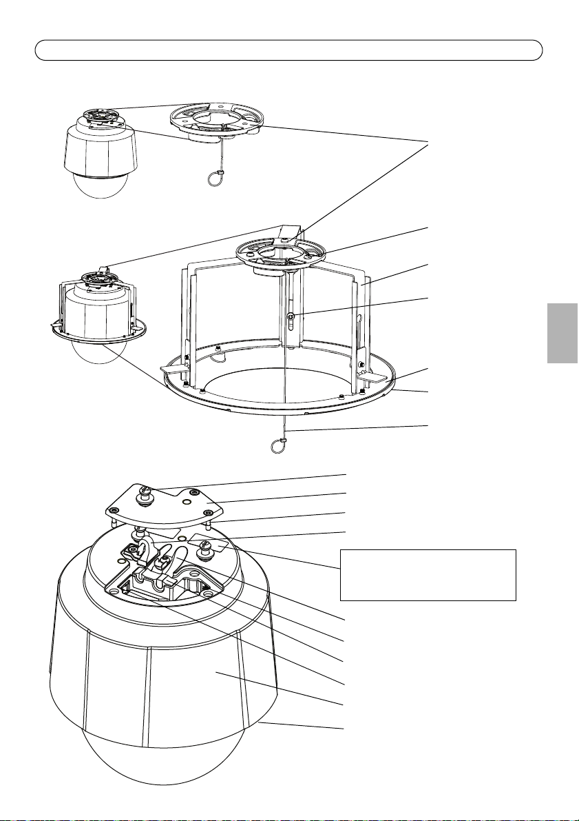
Page 6
Page 6 AXIS Q6032/Q6034/Q6035 Installation Guide
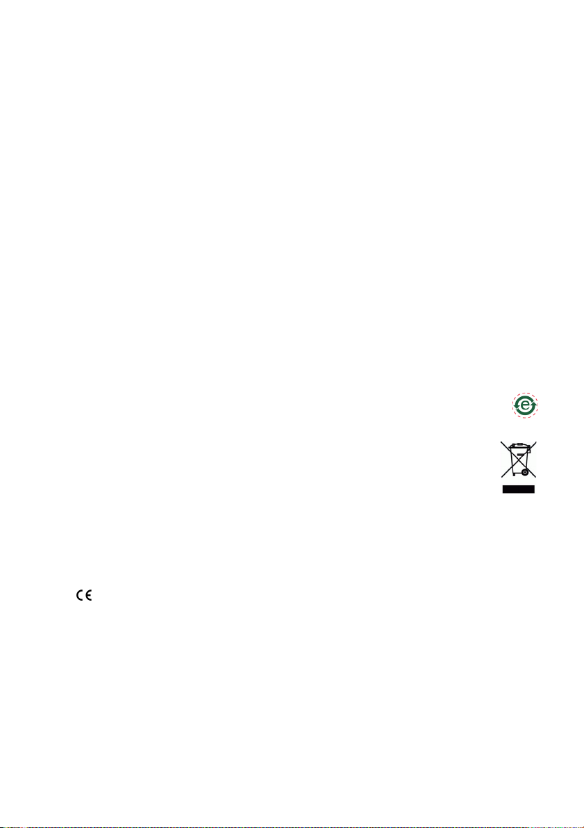
SDHC card slot
Status indicator LED
Control button
Dome bracket
Dome bracket
Dome cover
Dome ring
screw (4)
Dome ring
Camera unit
Dome cover
Power button
screw (4)
Hardware Overview
Page 7
AXIS Q6032/Q6034/Q6035 Installation Guide Page 7
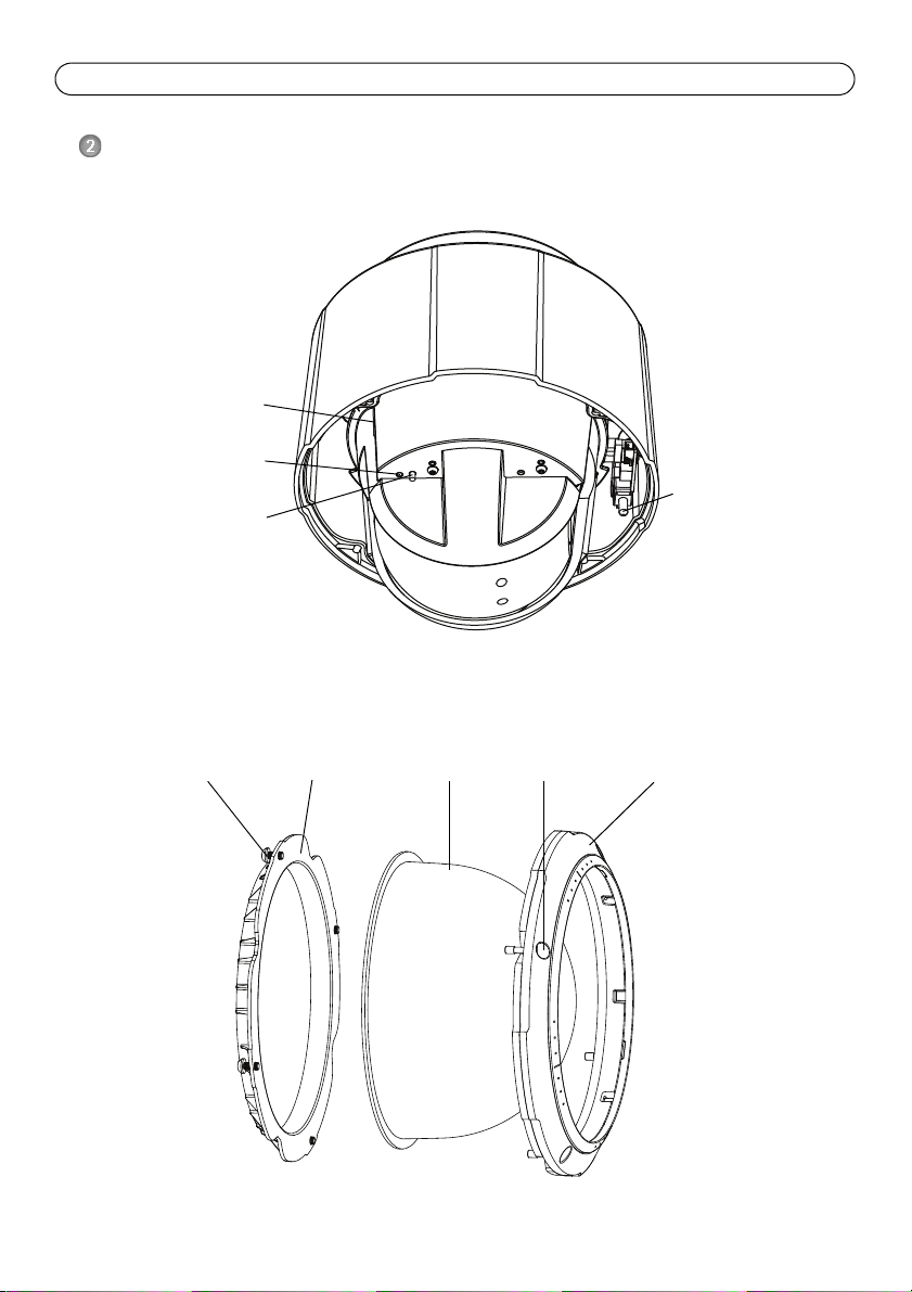
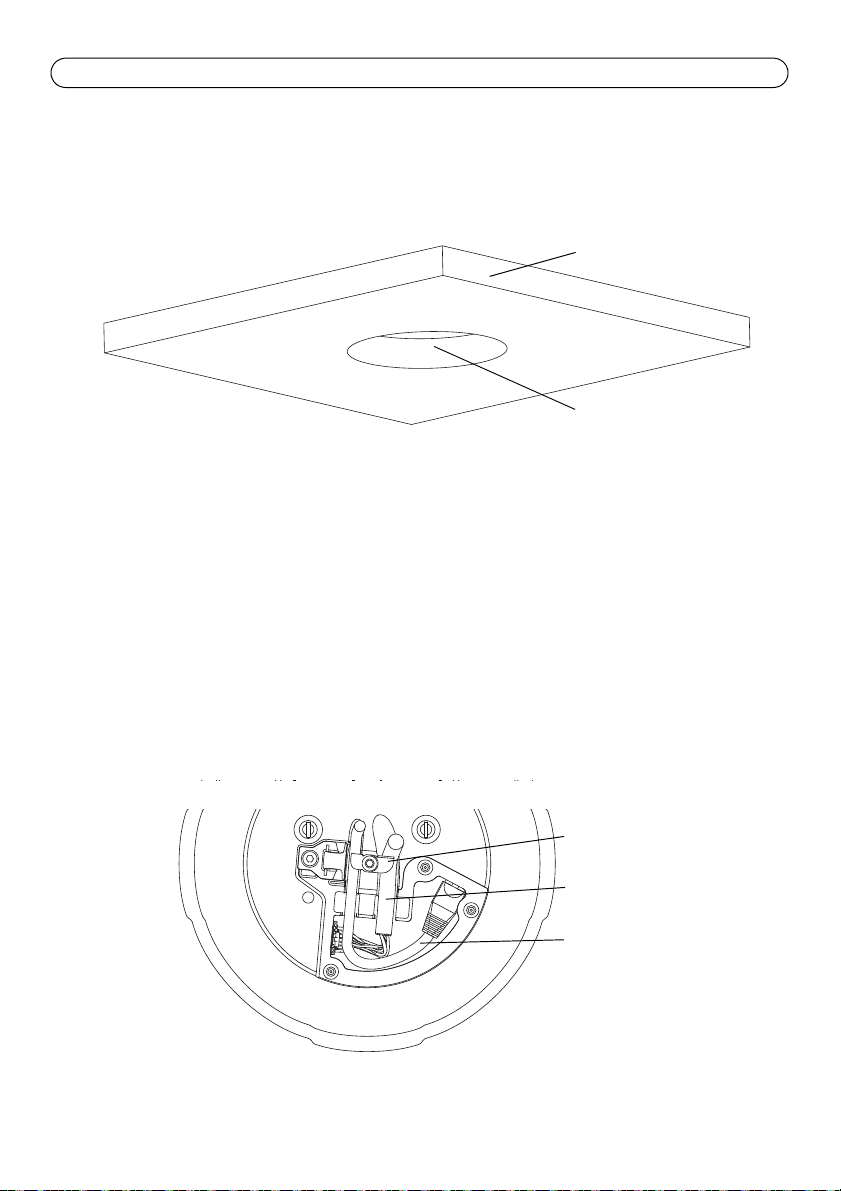
Drop ceiling mount
Bracket arm (3)
Bracket arm
Mounting plate
screw (3) and
Trim ring
Camera base lid
Multi-connector
Hook for safety wire
Network connector
Top cover screw (4)
Top cover
Unit holder (3)
Mounting plate
screw (3)
Camera base lid screw (3)
Cable tracks
Foam gasket
Safety wire
Part number (P/N) & Serial number (S/N).
The serial number may be required during the
installation.
Bracket ring
washer (3)
Hard ceiling mount
ENGLISH
Page 8

Page 8 AXIS Q6032/Q6034/Q6035 Installation Guide
Install the hardware
The network camera can be mounted with the cables routed through or along the wall or ceiling.
IMPORTANT! - To use the network camera outdoors, it must be installed in an approved
!
outdoor housing. Please see www.axis.com for more information on outdoor products.
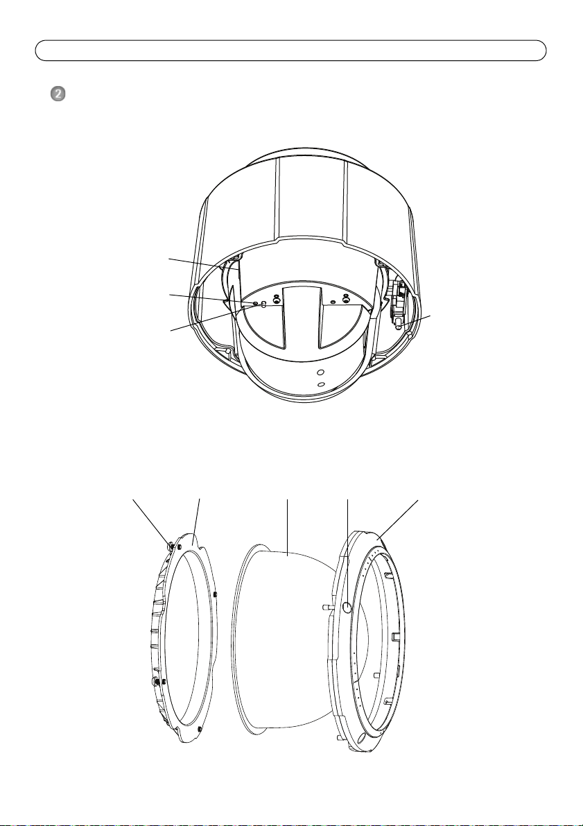
Prepare for installation
Read all the instructions before preparing to install the network camera since several installation
preparation steps require removing the dome ring and the dome cover and would benefit from
being completed together.
• The network camera is supplied with a clear transparent cover and a smoked transparent
cover. If required, follow the instructions
below to replace the dome cover.
• A standard or high capacity SD card (not included) is required to store images locally in the
network camera. Follow the instructions
dome cover and install an SD card.
Replace the clear/smoked dome cover (optional)
1. Loosen the 4 dome ring screws and remove the dome ring and the dome cover, see illustration
on page 6.
2. Remove the 4 dome bracket screws and remove the dome bracket and the dome cover from the
dome ring.
3. Attach the dome bracket and the dome cover to the dome ring and tighten the 4 screws.
4. If installing an SD card, refer to the instructions
5. Put the dome ring with the dome cover back in the original position and tighten the screws.
Replace the clear/smoked dome cover (optional)
Install an SD card (optional)
Install an SD card (optional)
, below to remove the
, below.
,
Note:
Be careful not to scratch or damage the dome cover. If possible, keep the protective plastic
on the dome cover until the installation is complete.
Install an SD card (optional)
1. Loosen the 4 dome ring screws and remove the dome ring and the dome cover, see illustration
on page 6.
2. Insert an SD card (not included) into the SDHC (Secure Digital High Capacity) card slot.
3. Put the dome ring with the dome cover back in the original position and tighten the screws.
Notes:
The SD card is automatically mounted when inserted into the SDHC card slot. However,
before removing the SD card it should be unmounted through the camera’s web pages. Go
to Setup > System Options > Storage > SD Card and click Unmount. For more information, please see the User Manual available from the AXIS Network Video Product CD supplied with this product or from the website at www.axis.com
Page 9
AXIS Q6032/Q6034/Q6035 Installation Guide Page 9
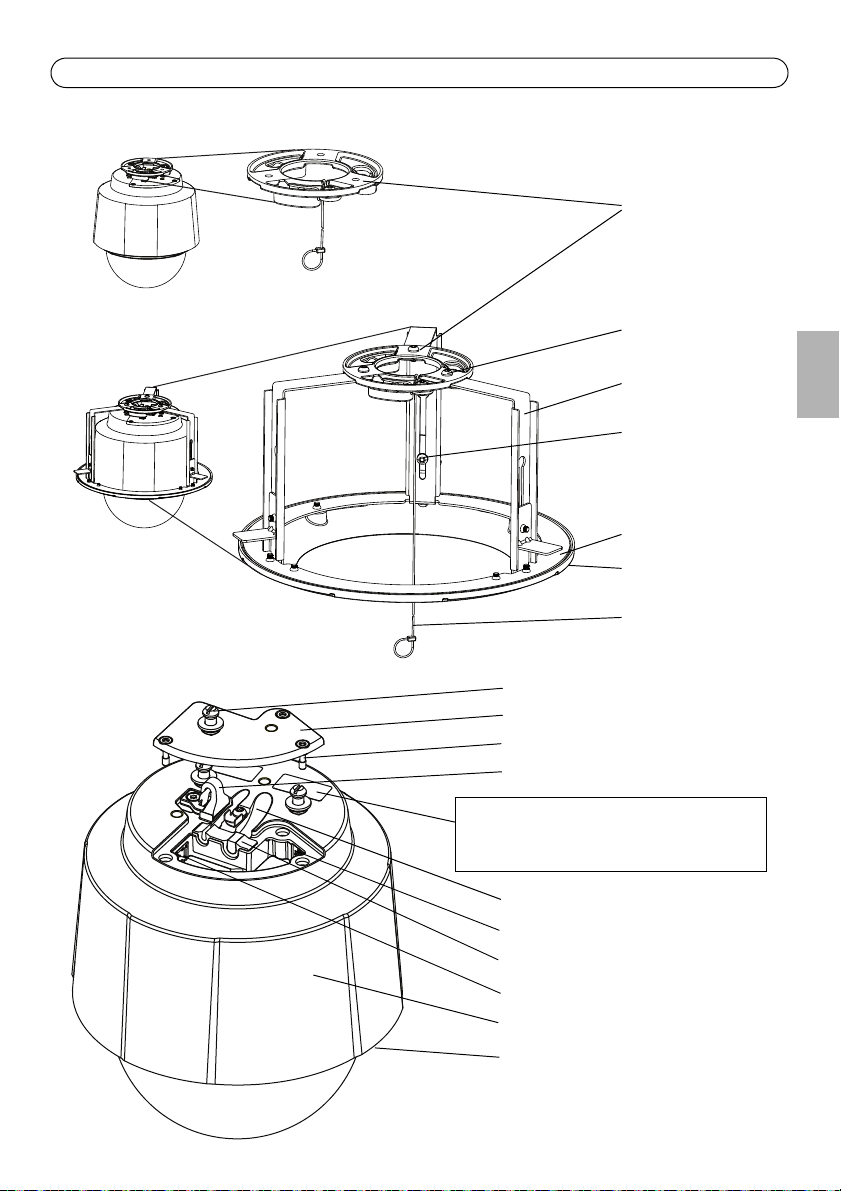
Mounting plate
Safety wire
Hard ceiling mount
1. Prepare the ceiling for installation of the mounting plate, use the supplied drill template to
position the holes. Make sure to use drill bits, screws and plugs that are appropriate for the
material.
2. Install the mounting plate. The arrow on the mounting plate will align with the logotype on the
camera.
3. Loosen the 3 camera base lid screws and remove the camera base lid, see illustration on page 7.
4. Secure the camera using the supplied safety wire.
5. Route and connect the network cable and the multi-connector cable, if applicable, to the
network camera. Be careful not to damage the cables when connecting them. Make sure the
foam gasket holes are aligned with the cable tracks and, if applicable, remove the cut-out piece
for the multi-connector cable from the foam gasket.
6. Put the camera base lid back in its original position and fasten the screws.
7. Slide the unit holders on the network camera into the slots on the mounting plate and rotate
the camera unit.
8. Install the High PoE Midspan 1-Port, see
13.
9. Check that the indicator LEDs on the midspan indicate the correct conditions, see the table on
page 24 for further details.
Install AXIS T8123 High PoE Midspan 1-port,
on page
ENGLISH
Page 10
Page 10 AXIS Q6032/Q6034/Q6035 Installation Guide
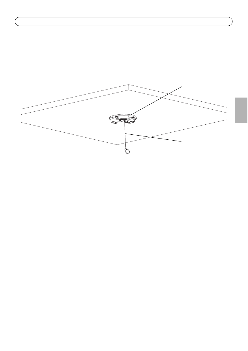
Ceiling tile
Hole diameter
225 mm (8.9 in.)
Multi-connector cable
Network cable
Cable holders
Drop ceiling mount
1. Remove the ceiling tile in which the drop ceiling mount is to be fitted.
2. Use the supplied template to mark the position for the 225 mm (8.9 in.) hole in the ceiling tile.
Cut around the template.
Notes:
• The combined weight of the camera and ceiling mount is approximately 3.2 kg (7.1 lb.). Check that
the ceiling material is strong enough to support this weight.
• The ceiling tile should be 5 mm–60 mm (0.2 in.–2.4 in.) thick.
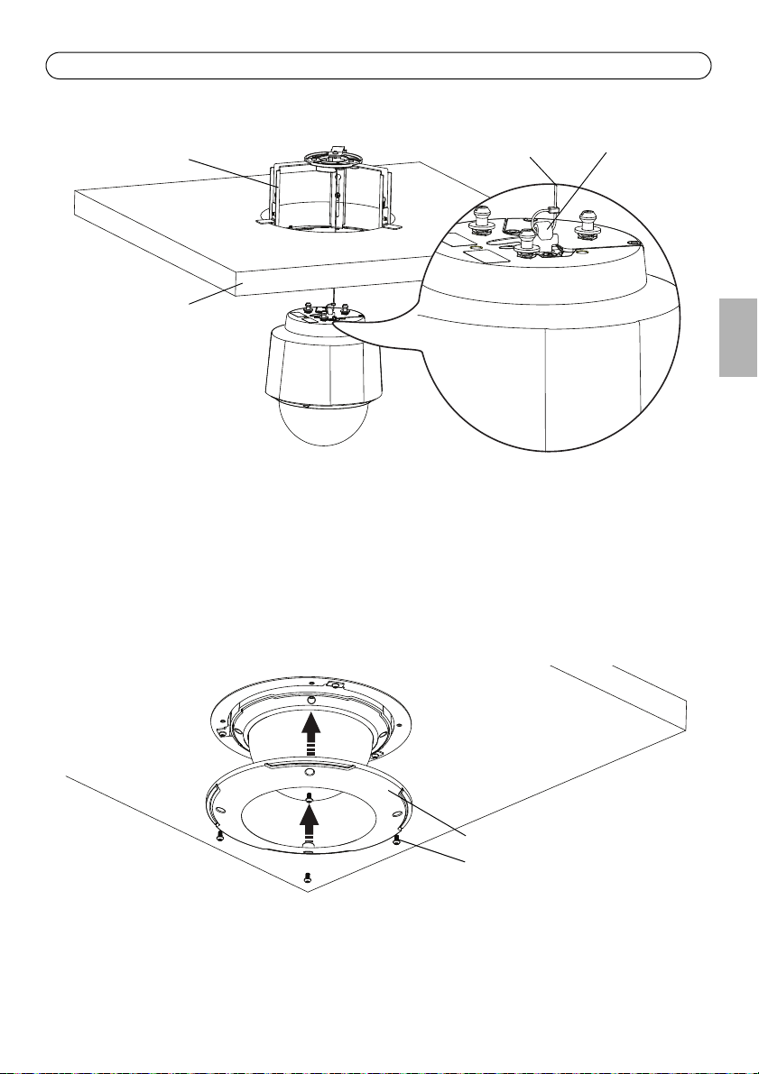
3. Put the ceiling bracket into the ceiling tile, see illustration on page 11. Make sure the arrows on
the mounting plate and the ceiling bracket are pointing in the same direction for the logotypes
on the camera and the trim ring to align.
4. Tighten the bracket arm screws using a Torx 20 screwdriver head.
5. Loosen the 3 camera base lid screws and remove the camera base lid, see illustration on page 7.
6. Route and connect the network cable and the multi-connector cable, if applicable, to the
network camera. Be careful not to damage the cables when connecting them. Make sure the
foam gasket holes are aligned with the cable tracks and, if applicable, remove the cut-out piece
for the multi-connector cable from the foam gasket. Turn the cable holders to keep the cables
in place, see illustration below.
7. Put the camera base lid back in its original position and fasten the screws.
Page 11
AXIS Q6032/Q6034/Q6035 Installation Guide Page 11
Safety wire
Ceiling tile
Ceiling bracket
Hook for
safety wire
Trim ring
Trim ring screws
8. Secure the camera using the supplied safety wire.
9. Slide the unit holders on the network camera into the slots on the mounting plate and rotate
the camera unit.
10. Install the High PoE Midspan 1-Port, see
Install AXIS T8123 High PoE Midspan 1-port,
on page
13.
11. Check that the indicator LEDs on the midspan indicate the correct conditions. See the table on
page 24 for further details.
12. Install the ceiling tile, with the camera mounted, into the ceiling.
13. Place the trim ring over the ceiling bracket and tighten the screws.
ENGLISH
Page 12
Page 12 AXIS Q6032/Q6034/Q6035 Installation Guide
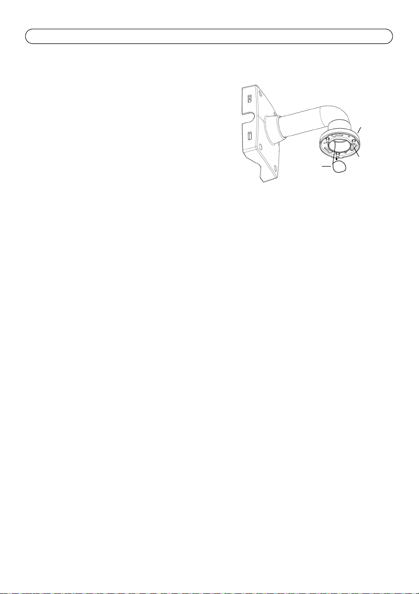
Wall bracket (mounting example)
Safety
wire
Slots for
Screws
Torx T30
unit holders
Bracket mount (optional accessory)
1. Install the selected bracket according to the
instructions supplied with the bracket. If drilling is
required, make sure to use drill bits, screws and
plugs that are appropriate for the material.
2. Loosen the 3 camera base lid screws and remove
the camera base lid, see illustration on page 7.
3. Route the network cable and the multi-connector
cable, if applicable, through the holes in the
mounting bracket.
4. Hook the camera to the safety wire on the bracket.
5. Connect the network cable and, if applicable, the
multi-connector cable to the network camera.
6. Install AXIS T8123, see
Install AXIS T8123 High PoE Midspan 1-port,
7. Put the camera base lid back in its original position.
8. Slide the unit holders on the network camera into the slots on the bracket and rotate the
camera unit.
9. Secure the network camera to the mounting bracket by fastening the 3 screws (Torx T30).
on page 13.
Page 13
AXIS Q6032/Q6034/Q6035 Installation Guide Page 13
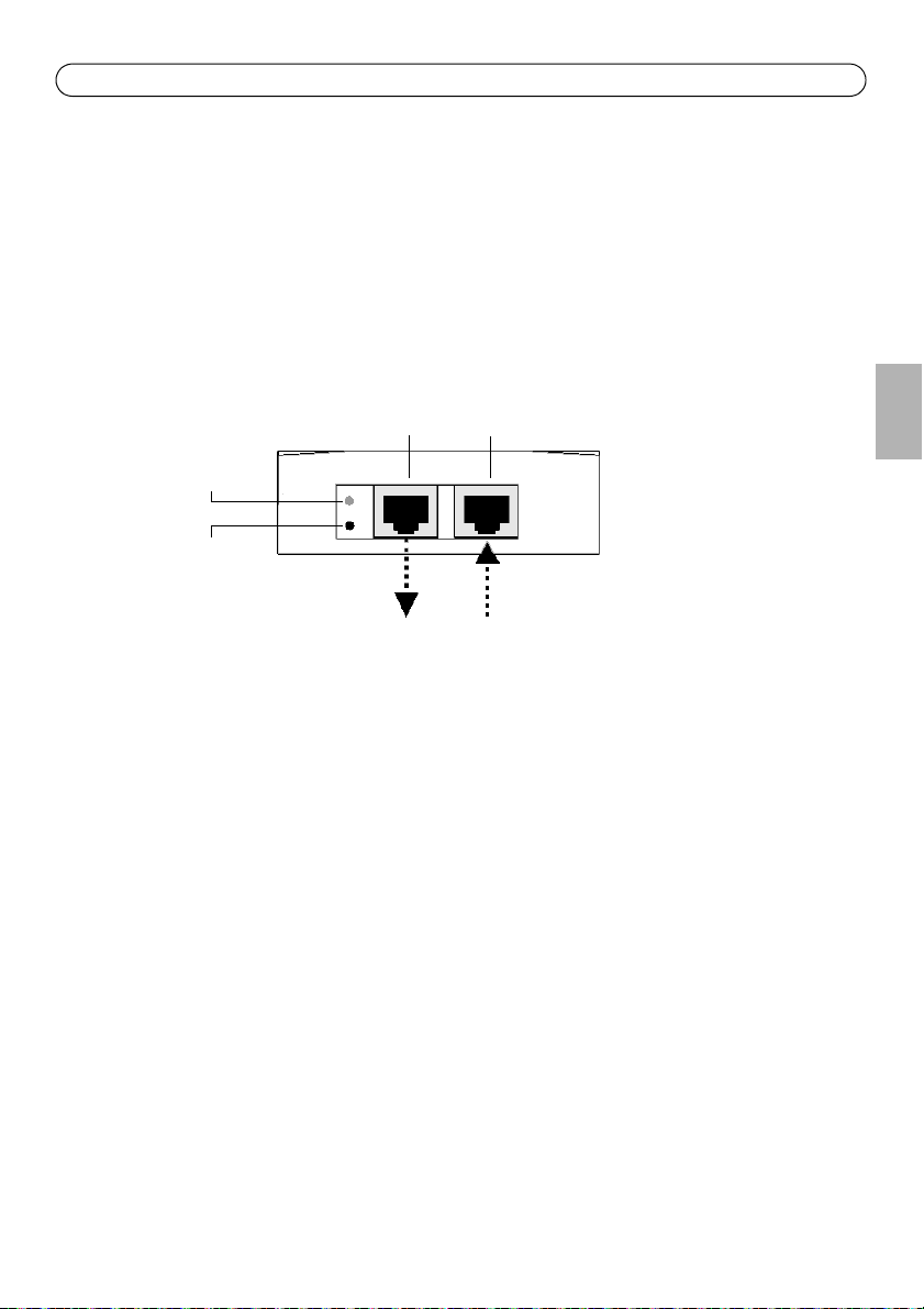
Data &
Power out Data in
Port
AC Input
connectivity
indicator
connectivity
indicator
Network camera Ethernet
AXIS T8123
Install AXIS T8123 High PoE Midspan 1-port
AXIS T8123 High PoE Midspan 1-port enables Axis network video products with high power
consumption to receive data and power over the same Ethernet cable. Follow these instructions to
connect AXIS T8123.
1. Connect AXIS T8123 (Data in) to the network switch using a standard network cable.
2. Connect AXIS T8123 (Data and Power Out) to the network camera, using the network cable that
has been connected to the camera.
3. Connect AXIS T8123 to an AC outlet (100–240 V AC), using the supplied power cable.
ENGLISH
For information on the LEDs on the midspan, see
Status indicators,
on page 24.
Page 14
Page 14 AXIS Q6032/Q6034/Q6035 Installation Guide
Assign an IP Address
Most networks today have a DHCP server that automatically assigns IP addresses to connected
devices. If your network does not have a DHCP server the network camera will use 192.168.0.90 as
the default IP address.
If you would like to assign a static IP address, the recommended method in Windows is either AXIS
IP Utility or AXIS Camera Management. Depending on the number of cameras you wish to install,
use the method that best suits your purpose.
Both of these free applications are available on the AXIS Network Video Product CD supplied with
this product, or they can be downloaded from www.axis.com
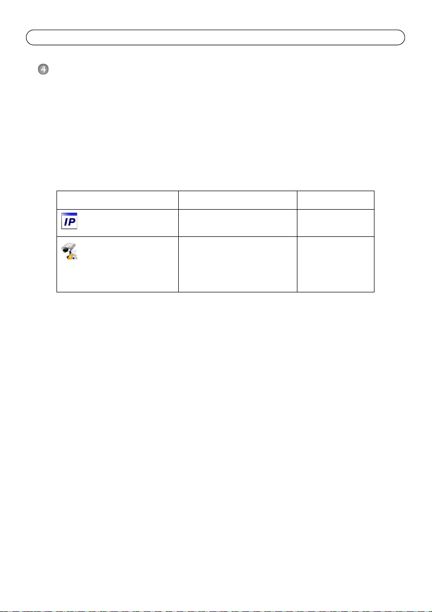
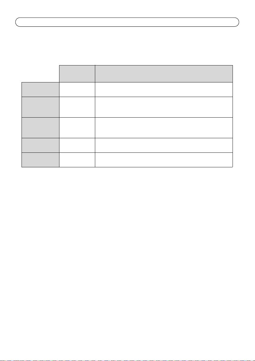
Method Recommended for Operating system
AXIS IP Utility
See page 15
AXIS Camera Management
See page 16
Notes:
• If assigning the IP address fails, check that there is no firewall blocking the operation.
• For other methods of assigning or discovering the IP address, e.g. in other operating systems, see
page 20.
Single camera
Small installations
Multiple cameras
Large installations
Installation on a different subnet
Windows
Windows 2000
Windows XP Pro
Windows 2003 Server
Windows Vista
Windows 7
Page 15
AXIS Q6032/Q6034/Q6035 Installation Guide Page 15
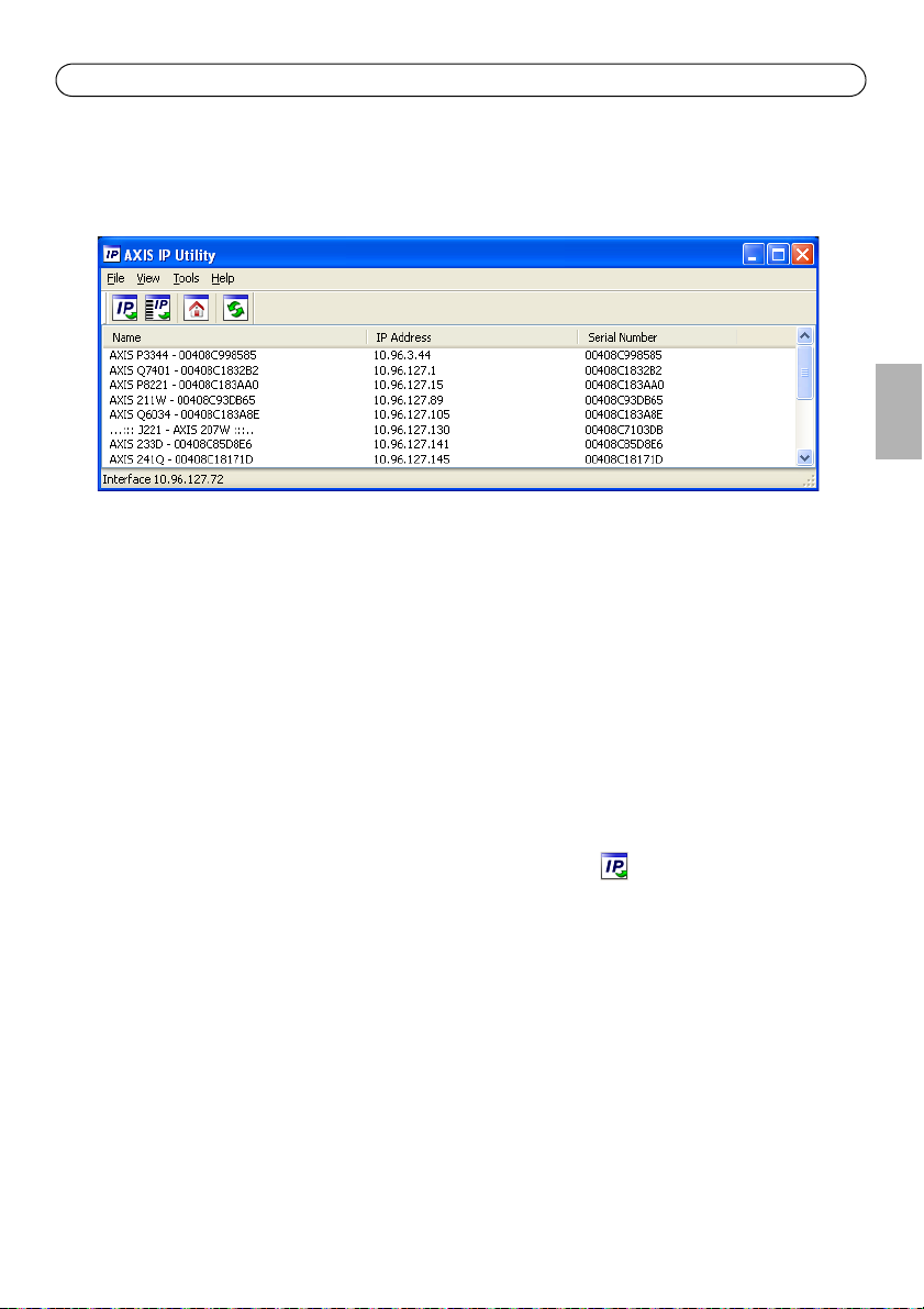
AXIS IP Utility - single camera/small installation
AXIS IP Utility automatically discovers and displays Axis devices on your network. The application
can also be used to manually assign a static IP address.
Note that the computer running AXIS IP Utility must be on the same network segment (physical
subnet) as the network camera.
Automatic discovery
1. Check that the network camera is connected to the network and that power has been applied.
2. Start AXIS IP Utility.
3. When the camera appears in the window, double-click it to open its home page.
4. See page 17 for instructions on how to assign the password.
ENGLISH
Assign the IP address manually (optional)
1. Acquire an unused IP address on the same network segment as your computer.
2. Select the network camera in the list.
3. Click the Assign new IP address to the selected device button and enter the IP address.
4. Click Assign and follow the on-screen instructions. Note that the camera must be restarted
within 2 minutes for the new IP address to be set.
5. Click Home Page to access the camera’s web pages.
6. See page 17 for instructions on how to set the password.
Page 16
Page 16 AXIS Q6032/Q6034/Q6035 Installation Guide
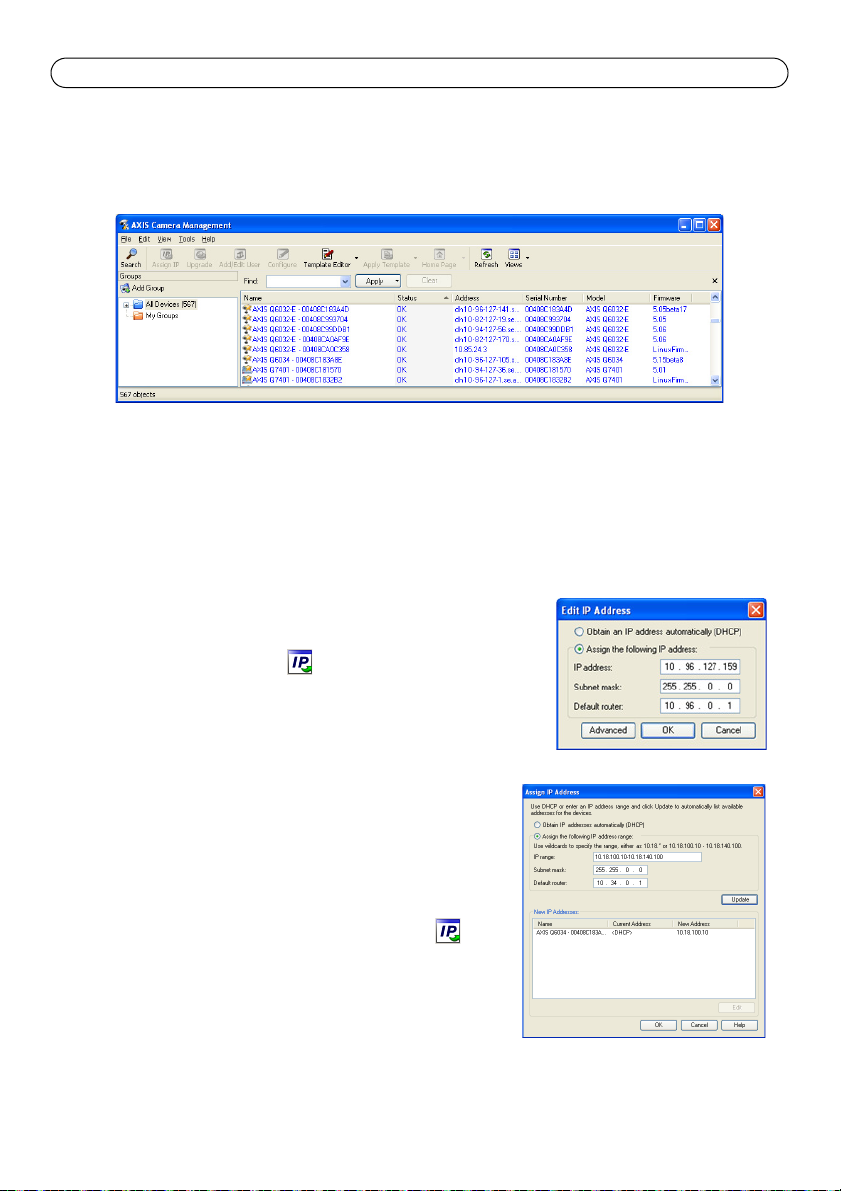
AXIS Camera Management - multiple cameras/large installations
AXIS Camera Management can automatically discover multiple Axis devices, show connection
status, manage firmware upgrades and set IP addresses.
Automatic discovery
1. Check that the camera is connected to the network and that power has been applied.
2. Start AXIS Camera Management. When the network camera appears in the window, right-click
the link and select Live View Home Page.
3. See page 17 for instructions on how to set the password.
Assign an IP address in a single device
1. Select the network camera in AXIS Camera Management and
click the Assign IP button.
2. Select Assign the following IP address and enter the IP
address, subnet mask and default router the device will use.
3. Click OK.
Assign IP addresses in multiple devices
AXIS Camera Management speeds up the process of assigning
IP addresses to multiple devices, by suggesting IP addresses
from a specified range.
1. Select the devices you wish to configure (different models
can be selected) and click the Assign IP button.
2. Select Assign the following IP address range and enter
the range of IP addresses, the subnet mask and default
router the devices will use.
3. Click Update. Suggested IP addresses are listed under New
IP Addresses and can be edited by selecting a device and
clicking Edit.
4. Click OK.
Page 17
AXIS Q6032/Q6034/Q6035 Installation Guide Page 17
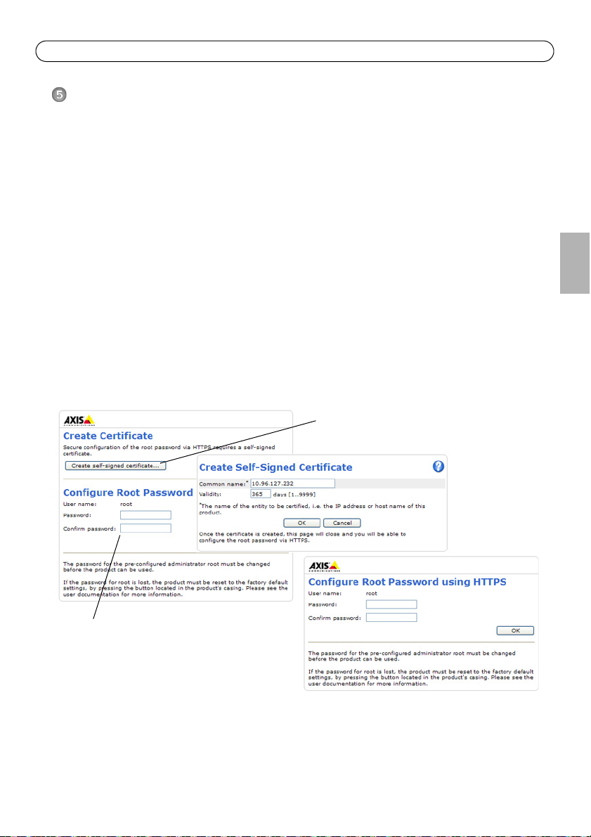
To configure the password directly
via an unencrypted connection, enter
the password here.
To create an HTTPS connection,
start by clicking this button.
Set the Password
To gain access to the product, the password for the default administrator user root must be set. This
is done in the ‘Configure Root Password’ dialog, which is displayed when the network camera is
accessed for the first time.
To prevent network eavesdropping when setting the root password, this can be done via an
encrypted HTTPS connection, which requires an HTTPS certificate.
Note: HTTPS (Hypertext Transfer Protocol over SSL) is a protocol used to encrypt the traffic between web
browsers and servers. The HTTPS certificate controls the encrypted exchange of information.
To set the password via a standard HTTP connection, enter it directly in the first dialog shown
below.
To set the password via an encrypted HTTPS connection, follow these steps:
1. Click the Create self-signed certificate button.
2. Provide the requested information and click OK. The certificate is created and the password can
now be set securely. All traffic to and from the network camera is encrypted from this point on.
3. Enter a password and then re-enter it to confirm the spelling. Click OK. The password has now
been configured.
ENGLISH
Page 18
Page 18 AXIS Q6032/Q6034/Q6035 Installation Guide
4. To log in, enter the user name “root” in the dialog as requested.
Note: The default administrator user name root cannot be deleted.
5. Enter the password as set above, and click OK.
Note: If the password is lost, the camera must be reset to the factory default settings. See page 25.
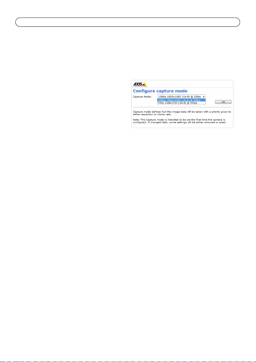
6. AXIS Q6035: The capture mode must be set
the first time the camera is accessed. Select
the desired Capture Mode from the dropdown list and click OK.
Note: The capture mode can be changed later
from the product’s web pages, but this
will reset most other settings. For more
information, see the online help or the
User Manual.
Page 19
AXIS Q6032/Q6034/Q6035 Installation Guide Page 19
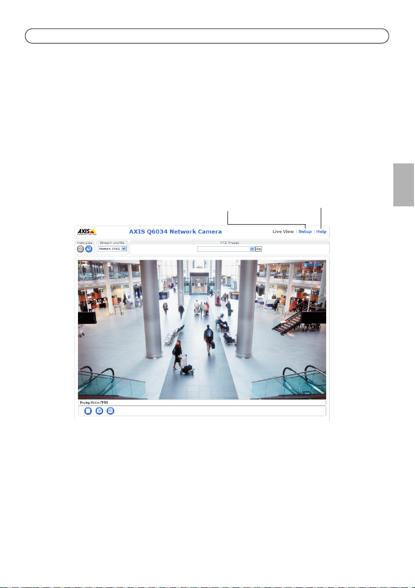
Setup - Provides all the
tools for configuring the
camera to requirements.
Help - Displays online
help on all aspects of
using the camera.
Access the video stream
The Live View page of the network camera is displayed, with links to the Setup tools, which allow
you to customize the camera.
If required, click Yes to install AMC (AXIS Media Control), which allows viewing of the video stream
in Internet Explorer. You will need administrator rights on the computer to do this.
If required, click the link to install missing decoders.
Note: To install AMC in Windows Vista, you must run Internet Explorer as an administrator. Right-click
the Internet Explorer icon and select Run as administrator.
ENGLISH
Page 20
Page 20 AXIS Q6032/Q6034/Q6035 Installation Guide
Other Methods of Setting the IP address
The table below shows the other methods available for setting or discovering the IP address. All
methods are enabled by default, and all can be disabled.
UPnP™
Bonjour
AXIS Dynamic
DNS Service
ARP/Ping
DHCP server
Use in operating
system
Windows When enabled on your computer, the camera is automatically detected
MAC OSX
(10.4 or later)
All A free service from Axis that allows you to quickly and simply install
All See below. The command must be issued within 2 minutes of
All To view the admin pages for the network DHCP server, see the server’s
Notes
and added to “My Network Places.”
Applicable to browsers with support for Bonjour. Navigate to the
Bojour bookmark in your browser (e.g. Safari) and click on the link to
access the camera’s web pages.
your camera. Requires an Internet connection with no HTTP proxy. See
www.axiscam.net for more information
connecting power to the camera.
own documentation.
AXIS Video Hosting System (AVHS)
The camera can also be connected to an AVHS service for hosted video. If you have subscribed to an
AVHS service, follow the instructions in the Service Provider’s Installation Guide. For more
information and help to find a local AVHS Service Provider, go to www.axis.com/hosting
A Camera owner authentication key is supplied with this product. The key is associated with the
camera’s unique serial number (S/N) as shown on the top of the label.
Note:
Save the key for future reference.
Page 21
AXIS Q6032/Q6034/Q6035 Installation Guide Page 21
Set the IP address with ARP/Ping
1. Acquire an IP address on the same network segment your computer is connected to.
2. Locate the serial number (S/N) on the product label on the camera.
3. Open a command prompt on your computer and enter the following commands:
Windows syntax: Windows example:
arp -s <IP Address> <Serial Number>
ping -l 408 -t <IP Address>
UNIX/Linux/Mac syntax: UNIX/Linux/Mac example:
arp -s <IP Address> <Serial Number> temp
ping -s 408 <IP Address>
4. Check that the network cable is connected to the camera and then start/restart the camera, by
disconnecting and reconnecting power.
5. Close the command prompt when you see ‘Reply from 192.168.0.125: ...’ or similar.
6. In your browser, type in http://<IP address> in the Location/Address field and press Enter on
your keyboard.
Notes:
• To open a command prompt in Windows: from the Start menu, select Run... and type cmd. Click OK.
• To use the ARP command in WIndows Vista, right-click the command prompt icon and select Run as
administrator.
• To use the ARP command on a Mac OS X, use the Terminal utility in Application > Utilities.
arp -s 192.168.0.125 00-40-8c-18-10-00
ping -l 408 -t 192.168.0.125
arp -s 192.168.0.125 00:40:8c:18:10:00 temp
ping -s 408 192.168.0.125
ENGLISH
Page 22

Page 22 AXIS Q6032/Q6034/Q6035 Installation Guide
Unit Connectors
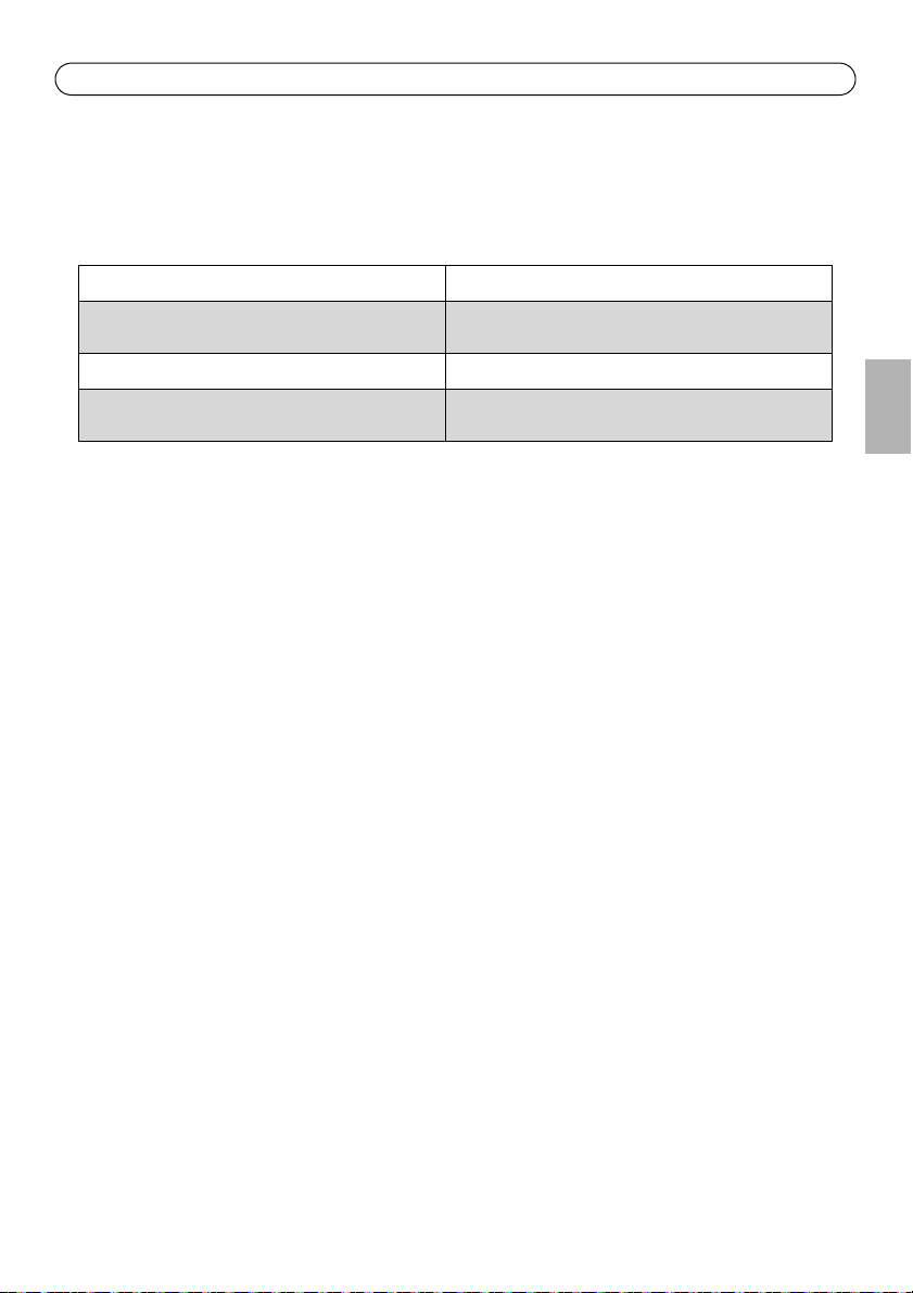
Network connector – RJ-45 Ethernet connector. Supports Power over Ethernet Plus (PoE+), see
table below. Use AXIS T8123 High PoE Midspan 1-port (included).
Product Maximum power consumption PoE (IEEE802.3at)
AXIS Q6032 21 W
AXIS Q6034 21 W
AXIS Q6035 23 W
Note:
Always use a shielded network cable (STP) between the camera and the end point and
ensure that the end point is properly grounded. Installations of Axis cameras using a
shielded network cable (STP) and a properly grounded end point have been tested to comply
with industry immunity standards’ levels such as surge protection. Any other installation
method will void the warranty and leave the unit at a risk.
Multi-connector – Terminal connector for connection of external equipment:
• Audio equipment
• Input/output (I/O) devices
• AC/DC power supply
When connecting external equipment to the network camera, a multi-connector cable is required in
order to maintain the IP52 rating. The multi-connector cable can be purchased from your Axis
reseller. For more information, please see the User Manual available from the AXIS Network Video
Product CD supplied with this product or from the website at www.axis.com
SDHC card slot – A standard or high capacity SD card (not included) is required to store images
locally in the network camera. To insert and remove the SD card, the dome ring and the dome cover
must be removed, see
Note:
Before removal, the SD card should be unmounted to prevent corruption of recordings. To
unmount the SD card, go to Setup > System Options > Storage > SD Card and click
Unmount. For more information, please see the User Manual available from the
AXIS Network Video Product CD supplied with this product or from the website at
www.axis.com
Install an SD card (optional),
on page 8.
Page 23
AXIS Q6032/Q6034/Q6035 Installation Guide Page 23
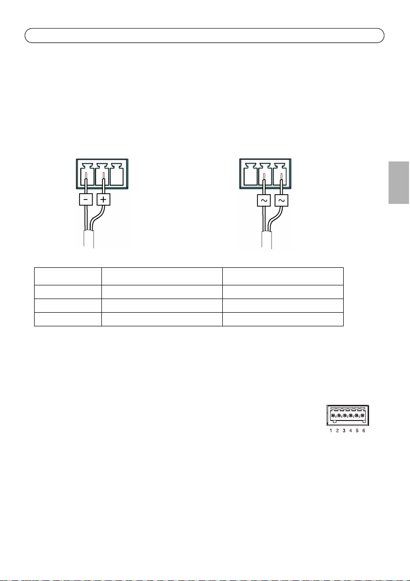
DC power input AC power input
Multi-connector cable (not included)
When connecting external equipment to the camera, a multi-connector cable is required in order to
maintain the camera’s IP52 rating. The multi-connector cable can be purchased from your Axis
reseller.
Connect the multi-connector cable to the camera’s multi connector, see illustration on page 7 and
instructions on page 9 and page 10. The cable provides the following connectors:
Power connector – 3-pin terminal block used for power input.
Product Power consumption DC Power consumption AC
AXIS Q6032 24-34 V DC, max. 19 W 20-24 V AC, max. 27 VA
AXIS Q6034 24-34 V DC, max. 19 W 20-24 V AC, max. 27 VA
AXIS Q6035 24-34 V DC, max. 20 W 20-24 V AC, max. 30 VA
Audio in (pink) – 3.5 mm input for a mono microphone, or a line-in mono signal (left channel is
used from a stereo signal).
Audio out (green) – 3.5 mm output for audio (line level) that can be connected to a public address
(PA) system or an active speaker with a built-in amplifier. A pair of headphones can also be
attached. A stereo connector must be used for the audio out.
I/O terminal connector – Used in applications for e.g. motion detection, event
triggering, time lapse recording and alarm notifications. In addition to an auxiliary
power and a GND pin, the I/O terminal connector has 4 pins that can be
configured as either input or output. These pins provide the interface to:
• Digital output - For connecting external devices such as relays and LEDs. Connected devices
can be activated by the VAPIX® Application Programming Interface, output buttons on the
Live View page or by an Event Type. The output will show as active (shown under
Events > Port Status if the alarm device is activated.
ENGLISH
Page 24
Page 24 AXIS Q6032/Q6034/Q6035 Installation Guide
• Digital input - An alarm input for connecting devices that can toggle between an open and
closed circuit, for example: PIRs, door/window contacts, glass break detectors, etc. When a
signal is received the state changes an the input becomes active (shown under
Events > Port Status).
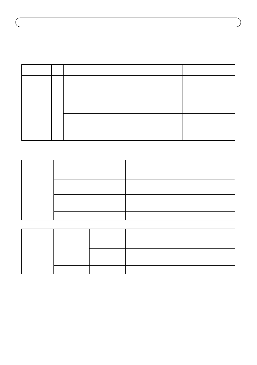
Function Pin Notes Specifications
GND 1 Ground
3.3 V DC
Power
Configurable
(input or
Output)
2 Can be used to power auxiliary equipment.
Note: This pin can only
3-6 Digital input – Connect to GND to activate, or leave floating
(unconnected) to deactivate.
Digital output – Uses an open-drain NFET transistor with the
source connected to GND. If used with an external relay, a
diode must be connected in parallel with the load, for protection against voltage transients.
be used as power out.
Max. load = 250 mA
Min. input = -40 V DC
Max. input = +40 V DC
Max. load = 100 mA
Max. voltage = +40 V DC
Status indicators
Product Color Indication
AXIS Q6032
AXIS Q6034
AXIS Q6035
Unlit Steady connection/normal operation
Amber Steady during system initiating and reset to factory
default. Flashes during firmware upgrade.
Amber/red No network connection
Red Firmware upgrade failure
Green Steady for 10 sec. after successful restart
Product LED
AXIS T8123 Port Unlit No camera connected
AC input Steady green AC power connected
Color Indication
Flashing Power overload or other input voltage error
Green Camera connected, normal behavior
Page 25
AXIS Q6032/Q6034/Q6035 Installation Guide Page 25
Tip!
Visit www.axis.com/techsup to check if there is updated firmware available for your network
camera. To see the currently installed firmware version, see Setup > About.
Resetting to the Factory Default Settings
To reset the camera to the original factory default settings, use the control button and the power
button on the side of the camera, see
Using the control and power buttons will reset all the parameters, including the IP address, to the
factory default settings:
1. Remove the dome ring and the dome cover, this will automatically disconnect power from the
camera, see
2. Press and hold the control button and the power button at the same time.
3. Continue to hold down the control and power buttons until the status indicator color changes
to amber (this may take up to 15 seconds).
4. Release the control button.
5. When the status indicator changes to green (which may take up to 1 minute), the process is
complete and the camera has been reset. The unit now has the default IP address 192.168.0.90
6. Release the power button and put the dome ring and dome cover back in their original position.
7. Re-assign the IP address, using one of the methods described in
14.
It is also possible to reset parameters to the original factory default settings via the web interface.
For more information, please see the online help or the User Manual available from the AXIS
Network Video Product CD supplied with this product.
Replace the clear/smoked dome cover (optional),
Hardware Overview,
on page 6, as described below:
on page 8.
Assign an IP Address,
on page
Accessing the Camera from the Internet
Once installed, your network camera is accessible on your local network (LAN). To access the
camera from the Internet, network routers must be configured to allow incoming traffic, which is
usually done on a specific port.
• HTTP port (default port 80) for viewing and configuration
• RTSP port (default port 554) for viewing H.264 video streams
Please refer to the documentation for your router for further instructions. For more information on
this and other topics, visit the Axis Support Web at www.axis.com/techsup
ENGLISH
Further Information
The User Manual is available from the Axis Web site at www.axis.com or from the AXIS Network
Video Product CD supplied with this product.
Page 26

Mesures de sécurité
Lisez attentivement ce guide d’installation avant d’installer le produit. Conservez le guide d’installation pour une
utilisation ultérieure.
ATTENTION!
• Pour éviter d’endommager le produit Axis, utilisez l’emballage d’origine ou un emballage équivalent pour le
transporter.
• Conservez le produit Axis dans un environnement sec et aéré.
• Évitez d’exposer le produit Axis à des vibrations, des chocs ou une trop forte pression et ne l’installez pas
sur des supports instables, ou encore sur des surfaces ou des murs instables ou vibrants; cela risquerait de
l’endommager.
• Utilisez uniquement des outils à main pour l’installation du produit Axis: l’utilisation d’outils électriques ou
l’usage excessif de la force risquent de l’endommager.
• N’utilisez ni produits chimiques, ni substances caustiques, ni nettoyeurs aérosol. Utilisez un chiffon humide
pour le nettoyage.
• N’utilisez que des accessoires conformes aux caractéristiques techniques du produit. Ceux-ci peuvent être
fournis par Axis ou un fournisseur tiers.
• Utilisez uniquement des pièces de rechange fournies ou recommandées par Axis.
• Ne tentez pas de réparer le produit vous-même, contactez Axis ou votre revendeur Axis pour tout problème
de maintenance.
IMPORTANT!
• Ce produit Axis doit être utilisé conformément aux lois et réglementations locales en vigueur.
• Pour pouvoir être utilisé à l’extérieur, ce produit Axis doit être placé dans un boîtier d’extérieur homologué.
Remplacement des piles
Ce produit Axis nécessite une pile au lithium CR2032 de 3V pour l’alimentation de son horloge en temps réel
interne. Dans des conditions normales d’utilisation, cette pile est censée durer au moins 5ans. Si la pile est
faible, le fonctionnement de l’horloge en temps réel peut être affecté et entraîner sa réinitialisation à chaque
mise sous tension. Un message enregistré apparaît lorsque la pile doit être remplacée. Ne remplacez la pile que
lorsque cela est nécessaire.
Si la pile doit être remplacée, veuillez contacter www.axis.com/techsup pour obtenir de l’aide.
• Le remplacement incorrect de la pile peut entraîner un risque d’explosion.
• Remplacez la pile par une pile identique ou équivalente uniquement, en respectant les recommandations du
fabricant.
• Jetez les piles usagées conformément aux consignes du fabricant.
Nettoyage de la bulle du dôme
• Veillez à ne pas rayer ou endommager la bulle du dôme. Ne nettoyez pas la bulle du dôme si elle semble
propre à l’œil nu et ne frottez jamais sa surface. Un nettoyage excessif peut l’endommager.
• Pour le nettoyage général de la bulle du dôme, il est recommandé d’utiliser un savon ou un détergent
neutre sans solvant, non abrasif, avec de l’eau et un chiffon doux. Rincez abondamment avec de l’eau douce
et tiède. Séchez à l’aide d’un chiffon doux pour éviter les salissures d’eau.
• N’utilisez jamais de détergents forts, d’essence, de benzène ou d’acétone, etc. et évitez toute exposition
directe aux rayons du soleil ou à des températures élevées lors du nettoyage.
Page 27

AXIS Q6032/Q6034/Q6035 Guide d'installation Page 27
AXIS Q6032/Q6034/Q6035
Guide d’installation
Ce guide d’installation explique comment installer la AXIS Q6032/Q6034/Q6035 PTZ Dome Network
Camera sur votre réseau. Pour toute autre question concernant l’utilisation du produit, reportezvous au manuel de l’utilisateur du produit, que vous trouverez sur le CD joint ou sur le site
www.axis.com
Procédure d’installation
1. Vérifiez le contenu de l’emballage par rapport à la liste ci-dessous.
2. Vue d’ensemble du matériel. Reportez-vous à la page 28.
3. Installation du matériel.
• Préparation de l’installation, reportez-vous à la page 30.
• Fixation au plafond, reportez-vous à la page 31.
• Fixation au faux plafond, reportez-vous à la page 32.
• Fixation du support (accessoire en option), reportez-vous à la page 34.
• Installation de l’injecteur High PoE AXIS T8123 à 1 port, reportez-vous à la page 35.
4. Attribution d’une adresse IP. Reportez-vous à la page 36.
5. Configuration du mot de passe. Reportez-vous à page 39.
Contenu de l’emballage
Élément Modèles/variantes/remarques
Caméra réseau AXIS Q6032/Q6034/Q6035
Bulle du dôme Bulle transparente non fumée (prémontée)
Bulle transparente fumée
Kit de montage Kit de fixation au plafond et au faux plafond
Injecteur High PoE AXIS T8123
CD CD du produit de vidéo sur IP AXIS comprenant la documentation, les outils
Documentation imprimée AXIS Q6032/Q6034/Q6035 Guide d’installation de la Network Camera (le
d’installation et les autres logiciels
présent document)
Document de garantie d’Axis
Gabarit de perçage
Étiquettes de numéro de série supplémentaires (2x)
Clé d’authentification AVHS
FRAN
Ç
AIS
Accessoires en option Accessoires de montage AXIS T91A
Câble multiconnexion pour la connexion d’E/S, audio et de l´alimentation
Consultez le site à l’adresse www.axis.com pour plus d’informations sur les
accessoires disponibles
Page 28
Page 28 AXIS Q6032/Q6034/Q6035 Guide d'installation
Logement de carte SDHC
Voyant d’état
Bouton de commande
Vis du support
Support du dôme
Bulle du dôme
Vis de l’anneau
du dôme (4)
Anneau du dôme
Caméra
Bulle du dôme
Bouton marche/arrêt
du dôme (4)
Présentation du matériel
Page 29
AXIS Q6032/Q6034/Q6035 Guide d'installation Page 29
Fixation au faux plafond
Bras de support (3)
Vis du bras
Plaque de fixation
de support (3) et
Rondelle décorative
Couvercle de base de la caméra
Multiconnecteur
Crochet pour fil de sécurité
Connecteur réseau
Vis du couvercle supérieur (4)
Couvercle supérieur
Support de rack (3)
Vis de fixation
de la plaque (3)
Vis du couvercle de base de la caméra (3)
Passages pour câble
Joint en mousse
Fil de sécurité
Référence et numéro de série.
Le numéro de série peut être demandé
pendant l’installation.
Anneau de support
rondelle (3)
Fixation au plafond
FRAN
Ç
AIS
Page 30

Page 30 AXIS Q6032/Q6034/Q6035 Guide d'installation
Installation du matériel
La caméra réseau peut être montée avec les câbles d’alimentation acheminés à travers le mur ou le
plafond ou le long de l’un d’eux.
IMPORTANT ! - Pour pouvoir utiliser la caméra réseau à l’extérieur, elle doit être placée
!
dans un caisson extérieur homologué. Visitez le site www.axis.com pour plus
d’informations sur le caisson extérieur.
Préparation de l’installation
Lisez toutes les instructions avant de préparer l’installation de la caméra réseau. En effet, de
nombreuses étapes de cette préparation requièrent le retrait de l’anneau et de la bulle du dôme et il
serait plus judicieux de les effectuer ensemble.
• La caméra réseau est fournie avec deux bulles transparentes (non fumée et fumée). Si
nécessaire, suivez les instructions décrites dans la
non fumé (facultatif)
• Une carte SD standard ou haute capacité (non fournie) est requise pour stocker des images
en local sur la caméra réseau. Suivez les instructions décrites dans la section
d’une carte SD (facultatif)
ci-après pour remplacer la bulle du dôme.
ci-après pour retirer la bulle du dôme et installer la carte SD.
Replacement de la bulle du dôme fumé/non fumé (facultatif)
1. Desserrez les quatre vis de l’anneau du dôme puis retirez ce dernier ainsi que la bulle du dôme,
voir l’illustrationn à la page 28.
2. Retirez les quatre vis du support du dôme puis enlevez ce dernier ainsi que la bulle du dôme de
l’anneau du dôme.
3. Fixez le support et la bulle du dôme à l’anneau du dôme puis serrez les quatre vis.
4. En cas d’installation de la carte SD, reportez-vous aux instructions décrites dans la section
Installation d’une carte SD (facultatif)
5. Remettez en place l’anneau et la bulle du dôme, puis serrez les vis.
ci-après.
Replacement de la bulle du dôme fumé/
Installation
Remarque :
Veillez à ne pas rayer ou endommager la bulle du dôme. Laissez, si possible, la protection en
plastique sur la bulle du dôme jusqu’à la fin de l’installation.
Installation d’une carte SD (facultatif)
1. Desserrez les quatre vis de l’anneau du dôme puis retirez ce dernier et la bulle du dôme, voir
l’illustration à la page 28.
2. Insérez une carte SD (non fournie) dans le logement de carte SDHC (Secure Digital High
Capacity).
Page 31

AXIS Q6032/Q6034/Q6035 Guide d'installation Page 31
Plaque de fixation
Fil de sécurité
3. Remettez en place l’anneau et la bulle du dôme, puis serrez les vis.
Remarques :
La carte SD est automatiquement installée une fois insérée dans le logement de carte
SDHC. Il est cependant nécessaire de désinstaller la carte SD à partir des pages Web de la
caméra avant de la retirer. Choisissez Setup > System Options > Storage > SD Card
(Configuration > Options système > Stockage > Carte SD), puis cliquez sur Unmount
(Désinstaller). Pour plus d’informations, consultez le manuel de l’utilisateur, disponible sur
le CD de la caméra réseau AXIS, fourni avec le produit ou en téléchargement sur le site Web
www.axis.com
Fixation au plafond
1. Préparez le plafond pour monter la plaque de fixation. Marquez les emplacements des trous à
l’aide du gabarit de perçage fourni. Assurez-vous que les forets, les vis et les fiches sont adaptés
au matériau.
2. Installez la plaque de fixation. La flèche située sur la plaque de fixation s’aligne avec le logo de
la caméra.
FRAN
Ç
AIS
3. Desserrez les trois vis du couvercle de base de la caméra, puis retirez le couvercle, voir
l’illustration à la page 29.
4. Fixez la caméra à l’aide du fil de sécurité fourni.
5. Acheminez le câble réseau et le câble multiconnexion, le cas échéant, puis branchez-les à la
caméra réseau. Veillez à ne pas endommager les câbles lors du branchement. Vérifiez que les
trous sur le joint en mousse sont alignés aux passages pour câble et, le cas échéant, enlevez
l’échancrure du joint en mousse pour laisser passer le câble multiconnexion.
6. Remettez en place le couvercle de base de la caméra, puis serrez les vis.
7. Glissez les supports de rack de la caméra réseau dans les logements de la plaque de fixation,
puis tournez la caméra.
8. Installez l’injecteur High PoE à 1 port, reportez-vous à la section
PoE AXIS T8123 à 1 port,
9. Vérifiez que les voyants lumineux sur l’injecteur indiquent les conditions correctes. Pour plus
d’informations, reportez-vous au tableau à la page 47.
à la page 35.
Installation de l’injecteur High
Page 32

Page 32 AXIS Q6032/Q6034/Q6035 Guide d'installation
Plaque de plafond
Diamètre du trou
225 mm (8,9 po)
Câble multiconnexion
Câble réseau
Dispositifs de support
du câble
Fixation au faux plafond
1. Retirez la plaque de plafond sur laquelle le kit de montage doit être fixé.
2. Utilisez le modèle fourni pour marquer l’emplacement du trou de 225 mm (8,9 po) dans la
plaque de plafond. Faites un trou suivant le contour du modèle.
Remarques :
• Le poids total de la caméra plus le kit de montage est environ 3,2 kg (7,1 livres). Assurez-vous que le
matériau du plafond est suffisamment solide pour supporter ce poids.
• L’épaisseur de la plaque de plafond doit être entre 5 mm et 60 mm (0,2 po et 2,4 po).
3. Posez le support sur la plaque de plafond, voir l’illustration à la page 33. Assurez-vous que les
flèches de la plaque de fixation et du support pour plafond sont orientées dans la même
direction pour aligner les logos de la caméra sur la rondelle décorative.
4. Serrez les vis du bras de support à l’aide d’un tournevis Torx 20.
5. Desserrez les trois vis du couvercle de base de la caméra, puis retirez le couvercle, voir
l’illustration à la page 29.
6. Acheminez le câble réseau et le câble multiconnexion, le cas échéant, puis branchez-les à la
caméra réseau. Veillez à ne pas endommager les câbles lors du branchement. Vérifiez que les
trous sur le joint en mousse sont alignés aux passages pour câble et, le cas échéant, enlevez
l’échancrure du joint en mousse pour laisser passer le câble multiconnexion. Tournez les
dispositifs de support du câble pour maintenir les câbles en place, voir l’illustration ci-dessous.
7. Remettez en place le couvercle de base de la caméra, puis serrez les vis.
Page 33

AXIS Q6032/Q6034/Q6035 Guide d'installation Page 33
Fil de sécurité
Plaque de plafond
Support pour
Crochet pour
fil de sécurité
installation au plafond
Rondelle décorative
Vis de la rondelle décorative
8. Fixez la caméra à l’aide du fil de sécurité fourni.
9. Glissez les supports de rack de la caméra réseau dans les logements de la plaque de fixation,
puis tournez la caméra.
10. Installez l’injecteur High PoE à 1 port, reportez-vous à la section
PoE AXIS T8123 à 1 port,
à la page 35.
Installation de l’injecteur High
11. Vérifiez que les voyants lumineux sur l’injecteur indiquent les conditions correctes. Pour plus
d’informations, reportez-vous au tableau de la page 47.
12. Installez la plaque de plafond (avec la caméra déjà montée) dans le plafond.
13. Placez la rondelle décorative sur le support pour plafond et serrez les vis.
FRAN
Ç
AIS
Page 34

Page 34 AXIS Q6032/Q6034/Q6035 Guide d'installation
Support mural (exemple de fixation)
Fil de
sécurité
Logements pour
T30
Vis Torx
supports de rack
Fixation du support (accessoire en option)
1. Installez le support choisi conformément aux
instructions fournies avec le support. S’il
s’avère nécessaire de percer, vérifiez que les
forets, vis et chevilles à utiliser sont appropriés
pour le matériau.
2. Desserrez les trois vis du couvercle de base de
la caméra, puis retirez le couvercle, voir
l’illustration à la page 29.
3. Acheminez le câble réseau et le câble
multiconnexion, le cas échéant, dans les trous
du support de fixation.
4. Accrochez la caméra au fil de sécurité du support.
5. Branchez le câble réseau et le câble multiconnexion, le cas échéant, à la caméra réseau.
6. Installez l’injecteur AXIS T8123, reportez-vous à la section
AXIS T8123 à 1 port,
à la page 35.
7. Remettez en place le couvercle de base de la caméra.
8. Glissez les supports de rack de la caméra réseau dans les logements du support, puis tournez la
caméra.
9. Fixez la caméra réseau au support de fixation à l’aide des trois vis (Torx T30).
Installation de l’injecteur High PoE
Page 35

AXIS Q6032/Q6034/Q6035 Guide d'installation Page 35
Sortie Données
Entrée données
Indicateur
Indicateur
de connexion
d’entrée CA
de connexion
de port
Caméra réseau Ethernet
AXIS T8123
et alimentation
Installation de l’injecteur High PoE AXIS T8123 à 1 port
L’injecteur High PoE AXIS T8123 à 1 port permet à la caméra réseau Axis consommant une
quantité importante d’énergie, de recevoir des données et de l’alimentation via le même câble
Ethernet. Procédez comme suit pour brancher l’injecteur AXIS T8123 :
1. Branchez l’injecteur AXIS T8123 (Données d’entrée) au commutateur réseau via un câble réseau
standard.
2. Branchez l’injecteur AXIS T8123 (Données et alimentation de sortie) à la caméra réseau, via un
câble réseau déjà branché à la caméra.
3. Branchez l’injecteur AXIS T8123 à une prise CA (100–240 V CA), à l’aide du câble
d’alimentation fourni.
FRAN
Ç
AIS
Pour plus d’informations sur les voyants lumineux de l’injecteur, reportez-vous à la section
d’état,
à la page 46.
Voyants
Page 36

Page 36 AXIS Q6032/Q6034/Q6035 Guide d'installation
Attribution d’une adresse IP
Aujourd’hui, la plupart des réseaux sont équipés d’un serveur DHCP qui attribue automatiquement
des adresses IP aux périphériques connectés. Si votre réseau ne possède pas de serveur DHCP, la
caméra réseau utilise l’adresse IP 192.168.0.90 comme adresse IP par défaut.
Si vous souhaitez paramétrer une adresse IP statique sous Windows, nous recommandons
l’utilisation de l’application AXIS IP Utility ou de l’application AXIS Camera Management. Selon le
nombre de caméras à installer, utilisez la méthode qui vous convient le mieux.
Ces deux applications gratuites sont disponibles sur le CD du produit de vidéo sur IP AXIS fourni
avec ce produit. Vous pouvez également les télécharger à partir du site www.axis.com
Méthode Recommandée pour Système
AXIS IP Utility
Voir page 37
AXIS Camera Management
Voir page 38
Remarques :
• En cas d’échec de l’attribution d’adresse IP, vérifiez qu’aucun pare-feu ne bloque l’opération.
• Pour connaître les autres méthodes d’attribution ou de détection de l’adresse IP, par exemple sous
d’autres systèmes d’exploitation, reportez-vous à la page 42.
Une seule caméra
Petites installations
Plusieurs caméras
Grandes installations
Installation sur un autre sousréseau
d’exploitation
Windows
Windows 2000
Windows XP Pro
Windows 2003 Server
Windows Vista
Page 37

AXIS Q6032/Q6034/Q6035 Guide d'installation Page 37
AXIS IP Utility : une seule caméra et une petite installation
AXIS IP Utility recherche et affiche automatiquement les périphériques Axis présents sur votre
réseau. Cette application peut également être utilisée pour attribuer manuellement une adresse IP
statique.
Notez que l’ordinateur exécutant l’application AXIS IP Utility doit se trouver sur le même segment
de réseau (sous-réseau physique) que la caméra réseau.
Détection automatique
1. Vérifiez que la caméra réseau est connectée au réseau et qu’elle se trouve sous tension.
2. Lancez AXIS IP Utility.
3. Lorsque l’icône de la caméra apparaît dans la fenêtre, double-cliquez dessus pour ouvrir la page
d’accueil correspondante.
4. Reportez-vous à la page 39 pour savoir comment configurer le mot de passe.
FRAN
Ç
AIS
Attribution manuelle de l’adresse IP (facultatif)
1. Trouvez une adresse IP inutilisée sur le même segment de réseau que celui de votre ordinateur.
2. Sélectionnez la caméra réseau dans la liste.
3. Cliquez sur le bouton Assign new IP address to the selected device (Attribuer une nouvelle
adresse IP au périphérique sélectionné) , puis saisissez l’adresse IP.
4. Cliquez sur le bouton Assign (Attribuer) et suivez les instructions qui s’affichent à l’écran. La
caméra doit être redémarrée dans les 2 minutes pour que la nouvelle adresse IP soit prise en
compte.
5. Cliquez sur le bouton Home Page (Page d’accueil) pour accéder aux pages Web de la caméra.
6. Reportez-vous à la page 39 pour savoir comment configurer le mot de passe.
Page 38

Page 38 AXIS Q6032/Q6034/Q6035 Guide d'installation
AXIS Camera Management : plusieurs caméras et de grandes installations
AXIS Camera Management est capable de détecter automatiquement plusieurs dispositifs Axis,
d’afficher leur état de connexion, de gérer les mises à niveau des micrologiciels et de définir les
adresses IP.
Détection automatique
1. Vérifiez que la caméra est connectée au réseau et sous tension.
2. Lancez AXIS Camera Management. Lorsque la caméra réseau apparaît dans la fenêtre, cliquez
sur le lien avec le bouton droit de la souris, puis sélectionnez Live View Home Page (Page
d’accueil – Vidéo en direct).
3. Reportez-vous à la page 39 pour savoir comment configurer le mot de passe.
Attribution d’une adresse IP à un seul périphérique
1. Sélectionnez la caméra réseau dans l’application AXIS Camera
Management, puis cliquez sur le bouton Assign IP (Attribuer une
adresse IP) .
2. Sélectionnez Assign the following IP address (Attribuer l’adresse IP
suivante) et saisissez l’adresse IP, le masque de sous-réseau et le
routeur par défaut que le périphérique utilisera.
3. Cliquez sur OK.
Attribution d’adresses IP à plusieurs périphériques
AXIS Camera Management accélère le processus d’attribution
d’adresses IP à plusieurs périphériques en suggérant des adresses IP
dans une plage spécifiée.
1. Sélectionnez les périphériques à configurer (il peut s’agir de
modèles différents), puis cliquez sur le bouton Assign IP
(Attribuer adresses IP) .
2. Sélectionnez Assign the following IP address range (Attribuer
la plage d’adresses IP suivante) et saisissez la plage d’adresses IP,
le masque de sous-réseau et le routeur par défaut que les périphériques utiliseront.
3. Cliquez sur Update (Mettre à jour). Les adresses IP suggérées sont énumérées sous le champ
New IP Addresses (Nouvelles adresses IP) et peuvent être modifiées en sélectionnant un
périphérique et en cliquant sur le bouton Edit (Modifier).
4. Cliquez sur OK.
Page 39

AXIS Q6032/Q6034/Q6035 Guide d'installation Page 39
Pour configurer directement le mot
de passe via une connexion cryptée,
saisissez le mot de passe à cet
Pour créer une connexion HTTPS,
cliquez sur ce bouton.
Configuration du mot de passe
Pour accéder au produit, le mot de passe par défaut de l’administrateur, root, doit être configuré.
Pour ce faire, utilisez la boîte de dialogue Configure Root Password (Configurer le mot de passe
root) qui s’affiche lors du premier accès à la caméra réseau.
Pour éviter les écoutes électroniques lors de la configuration du mot de passe root, utilisez une
connexion HTTPS cryptée nécessitant un certificat HTTPS.
Remarque : le protocole HTTPS (Hypertext Transfer Protocol over Secure Socket Layer) est utilisé pour
crypter le trafic entre les navigateurs Web et les serveurs. Le certificat HTTPS contrôle
l’échange crypté des informations.
Pour configurer le mot passe avec une connexion HTTP standard, saisissez directement le mot de
passe dans la première boîte de dialogue représentée ci-dessous.
Pour configurer le mot passe avec une connexion HTTPS cryptée, procédez comme suit :
1. Cliquez sur le bouton Create self-signed certificate (Créer un certificat autosigné).
2. Saisissez les informations demandées, puis cliquez sur OK. Le certificat est créé et le mot de
passe peut maintenant être configuré en toute sécurité. Tout le trafic vers et depuis la caméra
réseau est désormais crypté.
3. Saisissez un mot de passe, puis saisissez-le de nouveau pour confirmation. Cliquez sur OK. Le
mot de passe est maintenant configuré.
FRAN
Ç
AIS
Page 40

Page 40 AXIS Q6032/Q6034/Q6035 Guide d'installation
4. Pour vous connecter, saisissez le nom d’utilisateur « root » dans la boîte de dialogue à l’invite.
Remarque :le nom d’utilisateur par défaut de l’administrateur est root et il ne peut pas être
supprimé.
5. Saisissez le mot de passe tel que vous venez de le configurer et cliquez sur OK.
Remarque :si vous avez oublié votre mot de passe, vous devrez rétablir les paramètres d’usine par
défaut de votre caméra. Reportez-vous à la page 47.
6. AXIS Q6035: le mode de capture doit être
configuré lors du premier accès à la caméra
réseau. Sélectionnez le mode de capture
souhaité dans la liste déroulante et cliquez
sur OK.
Vous pouvez modifier le mode de capture
ultérieurement dans les pages web du produit,
mais cela réinitialisera la plupart des autres
paramètres. Pour plus d’informations,
reportez-vous à
Page 41

AXIS Q6032/Q6034/Q6035 Guide d'installation Page 41
Setup (Configuration) : contient tous les
outils nécessaires pour configurer la
caméra en fonction de vos besoins.
Help (Aide) : affiche l’aide
en ligne sur tout ce qui a
trait à l’utilisation de la
caméra.
Accès au flux de données vidéo
La page Live View (Vidéo en direct) de la caméra réseau s’affiche, avec des liens vers les outils de
configuration, lesquels vous permettent d’adapter la caméra à vos besoins.
Si nécessaire, cliquez sur Yes (Oui) pour installer AMC (AXIS Media Control) afin de visualiser le flux
de données vidéo dans Internet Explorer. Pour ce faire, vous devrez être connecté à l’ordinateur
avec des droits d’administrateur.
Si nécessaire, cliquez sur le lien pour installer les décodeurs manquants.
Remarque :pour installer AMC sous Windows Vista, vous devez exécuter Internet Explorer en tant
qu’administrateur. Cliquez avec le bouton droit de la souris sur l’icône Internet Explorer et
sélectionnez Exécuter en tant qu’administrateur.
FRAN
Ç
AIS
Page 42

Page 42 AXIS Q6032/Q6034/Q6035 Guide d'installation
Autres méthodes de configuration de l’adresse IP
Le tableau ci-dessous indique les autres méthodes permettant de configurer ou de déterminer
l’adresse IP. Toutes les méthodes sont activées par défaut et peuvent être désactivées.
UPnP™
Bonjour
AXIS Dynamic
DNS Service
ARP/Ping
Serveur DHCP
Utilisation sous
le système
d’exploitation
Windows Lorsque la caméra est activée sur votre ordinateur, elle est détectée et
MAC OSX
(10.4 ou version
ultérieure)
Tous Service Axis gratuit permettant d’installer rapidement et facilement
Tous Reportez-vous aux instructions ci-dessous. La commande doit être
Tous Pour consulter les pages administratives du serveur DHCP réseau,
Remarques
ajoutée automatiquement au dossier Favoris réseau.
Pour les navigateurs compatibles avec Bonjour. Accédez au signet de
Bonjour dans votre navigateur (par exemple Safari), puis cliquez sur le
lien permettant d’accéder aux pages Web de la caméra.
votre caméra. Nécessite une connexion Internet sans proxy HTTP. Pour
plus d’informations, visitez le site www.axiscam.net
saisie dans les deux minutes suivant
la mise sous tension de la caméra.
reportez-vous à la documentation du serveur.
AXIS Video Hosting System (AVHS)
La caméra peut aussi être connectée à un serveur AVHS pour les vidéos reçues. Si vous vous êtes
inscrit à un serveur AVHS, suivez les instructions décrites dans le Guide d’installation du fournisseur
de service. Pour obtenir des renseignements supplémentaires et trouver un fournisseur de service
AVHS, consultez le site www.axis.com/hosting
La Clé d’authentification du propriétaire de la caméra est inscrite sur la couverture arrière de ce
document. La clé est associée au numéro de série (S/N) unique de la caméra, comme décrit sur le
haut de l’étiquette.
Remarque :
Enregistrez la clé pour référence ultérieure.
Page 43

AXIS Q6032/Q6034/Q6035 Guide d'installation Page 43
Définition de l’adresse IP à l’aide d’ARP/Ping
1. Trouvez une adresse IP sur le même segment de réseau que celui de votre ordinateur.
2. Repérez le numéro de série (S/N) sur l’étiquette de la caméra.
3. Ouvrez une invite de commande sur votre ordinateur et saisissez les commandes suivantes :
Syntaxe pour Windows : Exemple pour Windows :
arp -s <Adresse IP> <Numéro de série>
ping -l 408 -t <Adresse IP>
Syntaxe pour UNIX/Linux/Mac : Exemple pour UNIX/Linux/Mac :
arp -s <Adresse IP> <Numéro de série> temp
ping -s 408 <Adresse IP>
arp -s 192.168.0.125 00-40-8c-18-10-00
ping -l 408 -t 192.168.0.125
arp -s 192.168.0.125 00:40:8c:18:10:00 temp
ping -s 408 192.168.0.125
4. Vérifiez que le câble réseau est connecté à la caméra, puis démarrez/redémarrez cette dernière
en débranchant puis en rebranchant l’alimentation.
5. Fermez la commande d’invite quand vous voyez « Reply from 192.168.0.125:... » (Réponse de
192.168.0.125 : ...) ou qu’un message similaire s’affiche.
6. Dans votre navigateur, saisissez http://<Adresse IP> dans le champ Emplacement/Adresse, puis
appuyez sur la touche Entrée de votre clavier.
Remarques :
• Ouvrir une invite de commande sous Windows : dans le menu Démarrer, sélectionnez Exécuter… et
tapez cmd. Cliquez sur OK.
• Pour utiliser la commande ARP sous Windows Vista, cliquez avec le bouton droit de la souris sur
l’icône d’invite de commande et sélectionnez Run as administrator (Exécuter en tant
qu’administrateur).
• Pour utiliser la commande ARP sous Mac OS X, utilisez l’utilitaire Terminal dans Application>
Utilitaires.
FRAN
Ç
AIS
Page 44

Page 44 AXIS Q6032/Q6034/Q6035 Guide d'installation
Connecteurs de l’appareil
Connecteur réseau: connecteur EthernetRJ-45. Prend en charge l’alimentation par Ethernet Plus
(PoE+), voir tableau ci-dessous. Utilisez l’injecteur High PoE AXIS T8123 à 1 port (fourni).
Produit Consommation d’énergie maximale (PoE+) IEEE802.3at
AXIS Q6032 21W
AXIS Q6034 21W
AXIS Q6035 23W
Remarque:
Utilisez toujours un câble réseau à paires torsadées blindé pour la liaison entre la caméra et le point
terminal. Assurez-vous également que le point terminal soit correctement mis à la terre. Les
installations des caméras Axis à l’aide d’un câble réseau à paires torsadées blindé et du point
terminal correctement mis à terre ont été soumises à des tests rigoureux, conformément aux
niveaux de la norme relative à l’immunité de l’industrie, notamment la protection contre les
surtensions. Toute autre méthode d’installation annule la garantie et expose le produit à des
risques.
Multiconnecteur : connecteur de terminaux pour la connexion d´équipement externe :
• Équipement audio
• Périphériques d’entrée/sortie (E/S)
• Bloc d’alimentation CA/CC
Lors du branchement d’un équipement externe à l’injecteur caméra réseau, un câble multiconnexion
est requis afin de maintenir la classification IP52. Le câble multiconnexion est disponible auprès de
votre revendeur Axis. Pour plus d’informations, consultez le manuel de l’utilisateur, disponible sur le
CD de la caméra réseau AXIS, fourni avec le produit ou en téléchargement sur le site Web
www.axis.com
Logement de carte SDHC : une carte mémoire SD standard ou haute capacité (non fournie) est
requise pour stocker des images en local sur la caméra réseau. Pour insérer et retirer la carte SD, il
est indispensable de retirer la bulle du dome, reportez-vous à la section
(facultatif),
Remarque :
à la page 30.
Vous devez désinstaller la carte SD avant de la retirer pour éviter que les enregistrements
soient corrompus. Pour désinstaller la carte SD, choisissez Setup > System Options >
Storage >SDCard (Configuration > Options système > Stockage > Carte SD), puis cliquez
sur Unmount (Désinstaller). Pour plus d’informations, consultez le manuel de l’utilisateur,
disponible sur le CD de la caméra réseau AXIS, fourni avec le produit ou en téléchargement
sur le site Web www.axis.com
Installation d’une carte SD
Page 45

AXIS Q6032/Q6034/Q6035 Guide d'installation Page 45
Alimentation en CC Alimentation en CA
Câble multiconnexion (non fourni)
Lors de la connexion d’un équipement externe à l’injecteur AXIS Q6032/Q6034/Q6035, un câble
multiconnexion est requis afin de maintenir la classification IP52 de la caméra. Le câble
multiconnexion est disponible auprès de votre revendeur Axis.
Branchez le câble multiconnexion au port multiconnexion, voir l’illustration à la page 29 et les
instructions à la page 31 et à la page 32. Les connecteurs que comprend le câble sont les suivants :
Connecteur d’alimentation : bloc terminal à trois broches utilisé pour la puissance d’entrée.
Produit Consommation d’énergie CC Consommation d’énergie CA
AXIS Q6032 24-34VCC, max. 19W 20-24VCA, max. 27VA
AXIS Q6034 24-34VCC, max. 19W 20-24VCA, max. 27VA
AXIS Q6035 24-34VCC, max. 20W 20-24VCA, max. 30VA
FRAN
Ç
AIS
Entrée audio (rose) : entrée de 3,5 mm pour microphone mono ou signal d’entrée mono (le canal
de gauche est utilisé pour le signal stéréo).
Sortie audio (vert) : sortie de 3,5 mm pour audio (niveau de ligne) qui peut être connectée à un
système d’annonce publique (PA) ou haut-parleur actif avec amplificateur intégré. Il est également
possible de connecter une paire d’écouteurs. Un connecteur stéréo doit être utilisé pour la sortie
audio.
Connecteur pour terminaux d’E/S : utilisé dans le cadre d’applications telles que
la détection de mouvement, le déclenchement d’événements, l’enregistrement à
intervalles et les notifications d’alarme. En plus d’une alimentation auxiliaire et
d’une broche de terre, le connecteur pour terminaux d’E/S possède 4 broches qui
peuvent être configurées comme entrées/sorties. Ces broches assurent l’interface
avec :
l’interface avec :Sortie numérique : permet de connecter des dispositifs externes, comme des relais
ou des voyants lumineux. Les dispositifs connectés peuvent être activés à l’aide de l’interface de
programmation VAPIX®, des boutons de sortie sur la page Live View (Vidéo en direct) ou à l’aide
d’un type d’événement. La sortie est considérée comme étant active (ce qui est visible dans
Events > Port Status (Événements - État du port) si le dispositif d’alarme est activé.
Page 46

Page 46 AXIS Q6032/Q6034/Q6035 Guide d'installation
• Entrée numérique : entrée d’alarme utilisée pour connecter des dispositifs pouvant passer
d’un circuit ouvert à un circuit fermé, par exemple, détecteurs infrarouge passifs, contacts
de porte/fenêtre, détecteurs de bris de verre, etc. Lorsqu’un signal est reçu, l’état change et
l’entrée devient active (sous Events > Port Status (Événements > État du port)).
Fonction Bro
GND 1 Mise à la terre
Alimentation
3,3 V CC
Configurable
(entrée ou
sortie)
Remarques Caractéristiques techniques
che
2 Peut servir à alimenter le matériel auxiliaire.
Remarque : cette broche ne peut être utilisée que
comme sortie d’alimentation.
3-6 Entrée numérique - Connectez-la à la terre pour
l’activer ou laissez-la flotter (ou déconnectée) pour la
désactiver.
Sortie numérique - Utilise un transistor NFET à drain
ouvert avec la source connectée à la terre. En cas
d’utilisation avec un relais externe, une diode doit être
connectée en parallèle avec la charge, en guise de
pro-tection contre les tensions transitoires.
Charge maximale = 250 mA
Entrée minimale = - 40 V CC
Entrée maximale = +40 V CC
Charge maximale = 100 mA
Tension maximale = +40 V CC
Voyants d’état
Produit Couleur Indication
AXIS Q6032
AXIS Q6034
AXIS Q6035
Éteint Connexion stable/fonctionnement normal
Orange En continu pendant l’initialisation du système et le
rétablissement des valeurs d’usine par défaut. Clignote pendant
les mises à niveau du microprogramme.
Orange/rouge Pas de connexion au réseau.
Rouge Échec de la mise à niveau du microprogramme
Vert Continu pendant 10 s après avoir redémarré avec succès
Produit DEL Couleur Indication
AXIS T8123 Indicateur Éteint Aucune caméra connectée
Clignotement Surcharge de l’alimentation ou autre erreur de tension d’entrée
Vert Caméra connectée, fonctionnement normal
Entrée CA Vert continu Alimentation CA connectée
Page 47

AXIS Q6032/Q6034/Q6035 Guide d'installation Page 47
Conseil :
Consultez le site www.axis.com/techsup pour vérifier si des micrologiciels mis à jour sont
disponibles pour votre caméra réseau. Pour connaître la version du micrologiciel
actuellement installée, reportez-vous à la page Setup > About (Configuration - À propos de).
Rétablissement des paramètres d’usine par défaut
Pour rétablir les paramètres d’usine par défaut de la caméra, utilisez le bouton de commande et le
bouton marche/arrêt situés sur le côté de la caméra, reportez-vous à la section
matériel,
Les boutons de commande et de démarrage permettent de rétablir les paramètres par défaut définis
en usine et de réinitialiser l’adresse IP :
à la page 28, comme décrit ci-après :
Présentation du
1. Enlevez la bulle du dome, cela mettra automatiquement la caméra hors tension, voir
Replacement de la bulle du dôme fumé/non fumé (facultatif),
2. Appuyez sur le bouton de commande et le bouton marche/arrêt en même temps et maintenezles enfoncés.
3. Maintenez les boutons de commande et de démarrage enfoncés jusqu’à ce que la couleur du
témoin d’état change en orange (cela peut prendre jusqu’à 15 secondes).
4. Relâchez le bouton de commande.
5. Lorsque le voyant d’état change en vert (ce qui peut prendre 1 minute), les paramètres par
défaut de la caméra ont été rétablis. L’adresse IP de la caméra est maintenant 192.168.0.90
6. Relâchez le bouton marche/arrêt et remettez en place la bulle du dome de la caméra.
7. Attribuez à nouveau l’adresse IP selon une des méthodes décrites dans la section
d’une adresse IP,
Il est également possible de rétablir les paramètres d’usine par défaut d’origine à partir de
l’interface Web. Pour plus d’informations, consultez l’aide en ligne ou le manuel de l’utilisateur,
disponibles sur le CD du produit de vidéo sur IP AXIS fourni avec le produit.
à la page 36.
à la page 30.
Attribution
Accès à la caméra via Internet
Une fois installée, votre caméra réseau est accessible sur votre réseau local (LAN). Pour accéder à la
caméra via Internet, les routeurs réseau doivent être configurés pour autoriser le trafic entrant, ce
qui est généralement réalisé sur un port spécifique.
• Le port HTTP (port 80 par défaut) pour l’affichage et la configuration
• Le port RTSP (port 554 par défaut) pour l’affichage des flux de données vidéo H.264
Pour plus d’informations, consultez la documentation du routeur. Pour plus d’informations à ce
sujet ou pour toute autre question, consultez la page d’assistance technique d’Axis à l’adresse
www.axis.com/techsup.
FRAN
Ç
AIS
Plus d’informations
Le manuel de l’utilisateur est disponible sur le site Web d’Axis (www.axis.com) et sur le CD du
produit de vidéo sur IP AXIS fourni avec le produit.
Page 48

Sicherheitsvorkehrungen
Bitte lesen Sie zunächst diese Installationsanleitung vollständig durch, bevor Sie mit der Installation Ihres
Produkts beginnen. Halten Sie die Installationsanleitung bereit, falls Sie darauf zurückgreifen müssen.
VORSICHT!
• Transportieren Sie das Axis-Produkt nur in der Originalverpackung bzw. in einer vergleichbaren Verpackung,
damit das Produkt nicht beschädigt wird.
• Lagern Sie das Axis-Produkt in einer trockenen und belüfteten Umgebung.
• Achten Sie darauf, dass das Axis-Produkt keinen Erschütterungen, Stößen oder starkem Druck ausgesetzt ist
und montieren Sie die Kamera nicht auf instabilen Halterungen oder auf instabilen und vibrierenden
Oberflächen oder Wänden. Dies könnte zu Beschädigungen des Produkts führen.
• Verwenden Sie keine elektrischen Werkzeuge zur Montage des Axis-Produkts, da diese das Produkt
beschädigen könnten.
• Verwenden Sie keine chemischen, ätzenden oder Aerosol-Reinigungsmittel. Verwenden Sie zur Reinigung
ein feuchtes Tuch.
• Verwenden Sie nur Zubehör, das den technischen Spezifikationen des Produkts entspricht. Dieses ist von
Axis oder Drittanbietern erhältlich.
• Verwenden Sie nur Ersatzteile, die von Axis empfohlen bzw. bereitgestellt wurden.
• Versuchen Sie nicht, das Produkt selbst zu reparieren. Wenden Sie sich bei Service-Angelegenheiten an Axis
oder an Ihren Axis-Händler.
WICHTIG!
• Verwenden Sie dieses Axis-Produkt unter Beachtung der geltenden rechtlichen Bestimmungen.
• Um dieses Axis-Produkt im Freien zu verwenden, muss es in einem zugelassenen Außengehäuse installiert
werden.
Batteriewechsel
Dieses Axis-Produkt ist mit einer 3,0V CR2032 Lithium-Batterie ausgestattet, mit der die interne Echtzeituhr
(RTC) versorgt wird. Unter normalen Bedingungen hält die Batterie mindestens 5Jahre. Bei entladener Batterie
ist der Betrieb der Echtzeituhr nicht mehr ausreichend gewährleistet, sodass die Uhr bei jedem Systemstart
zurückgesetzt wird. Sie erhalten eine Protokollnachricht, wenn ein Batteriewechsel erforderlich ist. Die Batterie
sollte erst bei Bedarf gewechselt werden.
Unter „www.axis.com/techsup“ finden Sie Informationen darüber, was Sie beim Austausch der Batterie beachten
müssen.
• Explosionsgefahr bei fehlerhaftem Batteriewechsel!
• Die Batterie muss durch dasselbe oder ein gleichwertiges Fabrikat ersetzt werden, das vom Hersteller
zugelassen ist.
• Verbrauchte Batterien sind gemäß Herstelleranweisungen zu entsorgen.
Reinigen der Kuppelabdeckung
• Achten Sie darauf, die Kuppelabdeckung nicht zu zerkratzen oder zu beschädigen. Reinigen Sie die
Kuppelabdeckung nicht, solange sie sauber aussieht, und polieren Sie niemals die Oberfläche. Übermäßiges
Reinigen kann die Oberfläche beschädigen.
• Zur allgemeinen Reinigung einer Kuppelabdeckung wird die Verwendung einer nicht aggressiven,
lösungsmittelfreien neutralen Seife bzw. eines solchen Reinigungsmittels zusammen mit Wasser und einem
weichen Tuch empfohlen. Spülen Sie gut mit sauberem, lauwarmem Wasser nach. Trocknen Sie die
Kuppelabdeckung mit einem weichen Tuch ab, um Wasserflecken zu vermeiden.
• Verwenden Sie niemals scharfe Reinigungsmittel, Benzin, Benzol, Aceton o.Ä. und führen Sie die Reinigung
nicht unter direkter Sonneneinstrahlung oder bei hohen Temperaturen durch.
Page 49

AXIS Q6032/Q6034/Q6035 Installationshandbuch Seite 49
AXIS Q6032/Q6034/Q6035
Installationshandbuch
In dieser Anleitung wird die Installation der AXIS Q6032/Q6034/Q6035 PTZ Dome Network Camera
in einem Netzwerk beschrieben. Alle weiteren Hinweise zur Verwendung des Produkts finden Sie im
Benutzerhandbuch, das auf der mitgelieferten CD oder auf unserer Website unter „www.axis.com“
zur Verfügung steht.
Installationsschritte
1. Prüfen Sie, ob alle in der nachfolgenden Liste aufgeführten Komponenten vorhanden sind.
2. Sehen Sie sich die Hardwareübersicht an. Siehe Seite 50.
3. Installieren Sie die Hardware.
• Vorbereitung der Installation, siehe Seite 52.
• Deckenmontage, siehe Seite 53.
• Hängedeckenmontage, siehe Seite 54.
• Montagehalterung (Sonderzubehör), siehe Seite 56.
• Installation des AXIS T8123 High PoE Midspan (1 Anschluss), siehe Seite 57.
4. Weisen Sie eine IP-Adresse zu. Siehe Seite 58.
5. Legen Sie das Kennwort fest. Siehe Seite 61.
Lieferumfang
Komponente Modelle/Varianten/Anmerkungen
Netzwerk-Kamera AXIS Q6032/Q6034/Q6035
Kuppelabdeckungen Transparente Klarglasabdeckung (vormontiert)
Getönte transparente Abdeckung
Montagesatz Montagesatz für die Befestigung an Decken und in Hängedecken
High PoE Midspan AXIS T8123
CD-ROM CD für AXIS-Netzwerkvideoprodukte einschließlich Produktdokumentation,
Gedruckte Dokumente AXIS Q6032/Q6034/Q6035 Network Camera Installationsanleitung (dieses
Installationswerkzeugen und anderer Software
Dokument)
Axis-Garantieerklärung
Bohrschablone
Zwei zusätzliche Etiketten mit der Seriennummer
AVHS-Authentifizierungsschlüssel
DEUTSCH
Optionales Zubehör AXIS T91A Montagezubehör
Mehrfachanschlusskabel zum Anschluss von E/A- und Audiogeräten sowie für
die Stromversorgung
Unter www.axis.com finden Sie Informationen zum verfügbaren Zubehör
Page 50

Seite 50 AXIS Q6032/Q6034/Q6035
SDHC-Speicher-
Statusanzeige (LED)
Steuertaste
Kuppelhalterungs-
Kuppelhalterung
Kuppelabdeckung
Kuppelring-
Schraube (4)
Kuppelring
Kameraeinheit
Kuppelabdeckung
Netztaste
Schraube (4)
karteneinschub
Hardwareübersicht
Page 51

AXIS Q6032/Q6034/Q6035 Installationshandbuch Seite 51
Hängedeckenmontage
Halterungsarm (3)
Schraube (3) und
Montageplatte
Unterlegscheibe (3)
Montagering
Kameragrundplatte
Mehrfachanschluss
Haken für Sicherheitsdraht
Netzwerkanschluss
Schraube für obere Abdeckung (4)
Obere Abdeckung
Kamerabefestigung (3)
Schraube (3) für
Montageplatte
Schraube für die Kameragrundplatte (3)
Kabelführungen
Schaumstoffdichtung
Sicherheitsdraht
Bestellnummer (P/N) und Seriennummer (S/N).
Die Seriennummer wird für die Installation
benötigt.
Halterungsring
Halterungsarmfür
Deckenmontage
DEUTSCH
Page 52

Seite 52 AXIS Q6032/Q6034/Q6035
Installieren der Hardware
Für die Montage der Netzwerk-Kamera können die Kabel durch oder entlang der Wand oder Decke
verlegt werden.
WICHTIG! - Um der Netzwerk-Kamera im Freien zu verwenden, muss sie in einem
!
zugelassenen Außengehäuse installiert werden. Auf unserer Homepage unter
„www.axis.com“ finden Sie weitere Informationen über Außengehäuse.
Vorbereitung der Installation
Lesen Sie zunächst alle Anweisungen, bevor Sie mit der Installationsvorbereitung der NetzwerkKamera beginnen. Bei einigen Vorbereitungsschritten müssen der Kuppelring und die
Kuppelabdeckung abgenommen werden, sodass es sinnvoll ist, diese Schritte zusammen
durchzuführen.
• Im Lieferumfang der Netzwerk-Kamera ist eine transparente Abdeckung in Klarglas und in
Rauchglas enthalten. Führen Sie bei Bedarf die Anweisungen unter
getönten Kuppelabdeckung (optional)
• Wenn Sie Bilder lokal in der Netzwerk-Kamera speichern möchten, benötigen Sie eine SDSpeicherkarte mit normaler oder hoher Kapazität (separat erhältlich). Führen Sie die unter
Installation einer SD-Speicherkarte (optional)
Kuppelabdeckung zu entfernen und eine SD-Speicherkarte zu installieren.
aus, um die Kuppelabdeckung auszutauschen.
beschriebenen Schritte aus, um die
Austauschen der klaren/
Austauschen der klaren/getönten Kuppelabdeckung (optional)
1. Lösen Sie die vier Kuppelringschrauben und nehmen Sie den Kuppelring und die
Kuppelabdeckung ab. Siehe Abbildung auf Seite 50.
2. Entfernen Sie die vier Kuppelhalterungsschrauben und nehmen Sie die Kuppelhalterung und die
Kuppelabdeckung vom Kuppelring ab.
3. Bringen Sie die Kuppelhalterung und die Kuppelabdeckung am Kuppelring an und ziehen Sie die
vier Schrauben fest.
4. Zur Installation einer SD-Speicherkarte führen Sie die unter
(optional)
5. Bringen Sie den Kuppelring mit der Kuppelabdeckung wieder an der ursprünglichen Position an
und ziehen Sie die Schrauben fest.
Hinweis:
Achten Sie darauf, die Kuppelabdeckung nicht zu zerkratzen oder zu beschädigen. Lassen
Sie, sofern möglich, den Kunststoffschutz bis zum Abschluss der Installation auf der
Kuppelabdeckung.
beschriebenen Schritte aus.
Installation einer SD-Speicherkarte
Page 53

AXIS Q6032/Q6034/Q6035 Installationshandbuch Seite 53
Montageplatte
Sicherheitsdraht
Installation einer SD-Speicherkarte (optional)
1. Lösen Sie die vier Kuppelringschrauben und nehmen Sie den Kuppelring und die
Kuppelabdeckung ab. Siehe Abbildung auf Seite 50.
2. Schieben Sie eine SD-Speicherkarte (separat erhältlich) in den SDHC-Speicherkartenschacht.
3. Bringen Sie den Kuppelring mit der Kuppelabdeckung wieder an der ursprünglichen Position an
und ziehen Sie die Schrauben fest.
Hinweise:
Die SD-Speicherkarte wird automatisch aktiviert, wenn Sie sie in den SDHCSpeicherkarteneinschub einsetzen. Bevor Sie die SD-Speicherkarte entfernen, müssen Sie
sie über die Webseiten der Kamera deaktivieren. Wählen Sie hierzu
Setup > System Options > Storage > SD Card (Setup > Systemoptionen > Speicher > SDSpeicherkarte) und klicken Sie auf Unmount (Deaktivieren). Weitere Informationen- hierzu
finden Sie im Benutzerhandbuch, das sich auf der mitgelieferten CD für AxisNetzwerkvideoprodukte -befindet und auf der Website unter „www.axis.com“ erhältlich ist.
Deckenmontage
1. Bereiten Sie die Befestigung der Montageplatte an der Decke vor. Markieren Sie die Position der
Bohrlöcher mithilfe der mitgelieferten Bohrschablone. Stellen Sie sicher, dass die Bohrerspitzen,
Schrauben und Dübel für das Wandmaterial geeignet sind.
2. Bringen Sie die Montageplatte an der Decke an. Der Pfeil auf der Montageplatte richtet sich auf
das Logo auf der Kamera aus.
DEUTSCH
3. Lösen Sie die drei Schrauben der Kameragrundplatte und nehmen Sie die Grundplatte ab. Siehe
Abbildung auf Seite 51.
4. Sichern Sie die Kamera mit dem mitgelieferten Sicherheitsdraht.
5. Verbinden Sie das Netzwerkkabel und bei Bedarf das Mehrfachanschlusskabel mit der
Netzwerk-Kamera. Achten Sie darauf, die Kabel beim Anschließen nicht zu beschädigen.
Vergewissern Sie sich, dass die Schaumstofflöcher auf die Kabelführungen ausgerichtet sind
und entfernen Sie ggf. das herausnehmbare Teil für das Mehrfachanschlusskabel aus der
Schaumstoffdichtung.
6. Bringen Sie die Kameragrundplatte wieder an der ursprünglichen Position an und ziehen Sie die
Schrauben fest.
Page 54

Seite 54 AXIS Q6032/Q6034/Q6035
Deckenplatte
Lochdurchmesser
225 mm (8,9 Zoll)
7. Schieben Sie die Kamerabefestigungen an der Netzwerk-Kamera in die Aussparungen in der
Montageplatte und drehen Sie die Kameraeinheit.
8. Installieren Sie den High PoE Midspan (1 Anschluss), siehe
PoE Midspan (1 Anschluss),
9. Überprüfen Sie, ob die LED-Anzeigen die Betriebszustände korrekt angeben. Weitere
Informationen hierzu finden Sie in der Tabelle auf Seite 68.
auf Seite 57.
Installation des AXIS T8123 High
Hängedeckenmontage
1. Nehmen Sie die Deckenplatte ab, in der die Halterung für Hängedecken angebracht werden soll.
2. Markieren Sie mithilfe der mitgelieferten Schablone die Position des 225-mm-Lochs in der
Deckenplatte. Schneiden Sie das Loch entlang der Schablone aus.
Hinweise:
• Das Gesamtgewicht von Kamera und Deckenhalterung beträgt etwa 3,2 kg. Vergewissern Sie sich,
dass das Deckenmaterial stabil genug ist, um dieses Gewicht zu tragen.
• Die Stärke der Deckplatte sollte 5 mm bis 60 mm betragen.
3. Bringen Sie die Deckenhalterung in der Deckenplatte an. Siehe Abbildung auf Seite 55. Stellen
Sie sicher, dass die Pfeile auf der Montageplatte und der Deckenhalterung in dieselbe Richtung
weisen, damit die Logos auf der Kamera und der Montagering aufeinander ausgerichtet sind.
4. Ziehen Sie die Schrauben des Halterungsarms mit einem Torx-Schraubenzieher für Torx 20Schrauben fest.
5. Lösen Sie die drei Schrauben der Kameragrundplatte und nehmen Sie die Grundplatte ab. Siehe
Abbildung auf Seite 51.
Page 55

AXIS Q6032/Q6034/Q6035 Installationshandbuch Seite 55
Mehrfachanschlusskabel
Netzwerkkabel
Kabelhalter
Sicherheitsdraht
Deckenplatte
Deckenhalterung
Haken für
Sicherheitdraht
6. Verbinden Sie das Netzwerkkabel und bei Bedarf das Mehrfachanschlusskabel mit der
Netzwerk-Kamera. Achten Sie darauf, die Kabel beim Anschließen nicht zu beschädigen.
Vergewissern Sie sich, dass die Schaumstofflöcher auf die Kabelführungen ausgerichtet sind
und entfernen Sie ggf. das herausnehmbare Teil für das Mehrfachanschlusskabel aus der
Schaumstoffdichtung. Drehen Sie die Kabelhalter so, dass die Kabel in ihrer Position gehalten
werden (siehe nachfolgende Abbildung).
7. Bringen Sie die Kameragrundplatte wieder an der ursprünglichen Position an und ziehen Sie die
Schrauben fest.
8. Sichern Sie die Kamera mit dem mitgelieferten Sicherheitsdraht.
9. Schieben Sie die Kamerabefestigungen an der Netzwerk-Kamera in die Aussparungen in der
Montageplatte und drehen Sie die Kameraeinheit.
10. Installieren Sie den High PoE Midspan (1 Anschluss), siehe
PoE Midspan (1 Anschluss),
auf Seite 57.
11. Überprüfen Sie, ob die LED-Anzeigen auf dem Midspan die Betriebszustände korrekt angeben.
Installation des AXIS T8123 High
Weitere Informationen hierzu finden Sie in der Tabelle auf Seite 68.
DEUTSCH
Page 56

Seite 56 AXIS Q6032/Q6034/Q6035
Montagering
Montageringschrauben
Wandhalterung (Montagebeispiel)
Sicherheitsdraht
Aussparungen
Schrauben
Torx T30-
für Kamerabefestigungen
12. Montieren Sie die Deckenplatte mit der montierten Kamera in die Decke.
13. Platzieren Sie den Montagering über der Deckenhalterung und ziehen Sie die Schrauben fest.
Montagehalterung (Sonderzubehör)
1. Montieren Sie die gewünschte Halterung gemäß
den im Lieferumfang des Montagesatzes
enthaltenen Anweisungen. Falls das Bohren von
Löchern erforderlich ist, stellen Sie sicher, dass die
Bohrerspitzen, Schrauben und Dübel für den
Baustoff der Wand geeignet sind.
2. Lösen Sie die drei Schrauben der
Kameragrundplatte und nehmen Sie die
Grundplatte ab. Siehe Abbildung auf Seite 51.
3. Führen Sie das Netzwerkkabel und bei Bedarf das
Mehrfachanschlusskabel durch die Löcher in der
Halterung.
4. Haken Sie die Kamera in den Sicherheitsdraht an der Halterung ein.
5. Verbinden Sie das Netzwerkkabel und bei Bedarf das Mehrfachanschlusskabel mit der
Netzwerk-Kamera.
6. Installieren Sie den AXIS T8123, siehe
Anschluss),
auf Seite 57.
7. Bringen Sie die Kameragrundplatte wieder an der ursprünglichen Position an.
8. Schieben Sie die Kamerabefestigungen an der Netzwerk-Kamera in die Aussparungen in der
Halterung und drehen Sie die Kameraeinheit.
9. Befestigen Sie die Netzwerk-Kamera an der Halterung, indem Sie die drei Schrauben (Torx T30)
anziehen.
Installation des AXIS T8123 High PoE Midspan (1
Page 57

AXIS Q6032/Q6034/Q6035 Installationshandbuch Seite 57
Daten- und
Stromausgang Dateneingang
Port-
Netzeingangs-
verbindungs-
anzeige
verbindungs-
anzeige
Netzwerk-Kamera Ethernet
AXIS T8123
Installation des AXIS T8123 High PoE Midspan (1 Anschluss)
Mit dem AXIS T8123 High PoE Midspan (1 Anschluss) können Netzwerk-Videoprodukte von Axis mit
einem großen Stromverbrauch über dasselbe Ethernet-Kabel sowohl mit Daten als auch mit Strom
versorgt werden. Führen Sie zum Verbinden des AXIS T8123 die folgenden Schritte aus.
1. Verbinden Sie den AXIS T8123 (Dateneingang) über ein Standard-Netzwerkkabel mit dem
Netzwerk-Switch.
2. Verbinden Sie den AXIS T8123 (Daten- und Stromausgang) über das zuvor an die Kamera
angeschlossene Netzwerkkabel mit der Netzwerk-Kamera.
3. Schließen Sie den AXIS T8123 über das mitgelieferte Netzkabel an eine Netzsteckdose (100 bis
240 V Wechselstrom) an.
DEUTSCH
Informationen zu den LEDs auf dem Midspan finden Sie unter
Statusanzeigen,
auf Seite 68.
Page 58

Seite 58 AXIS Q6032/Q6034/Q6035
Zuweisen einer IP-Adresse
In den meisten Netzwerken ist heutzutage ein DHCP-Server eingebunden, der angeschlossenen
Geräten automatisch IP-Adressen zuweist. Wenn Ihr Netzwerk über keinen DHCP-Server verfügt,
wird für die Netzwerk-Kamera die Standard-IP-Adresse 192.168.0.90 verwendet.
Zum Zuweisen einer statischen IP-Adresse stehen unter Windows die Programme AXIS IP Utility
und AXIS Camera Management zur Verfügung. Verwenden Sie die Methode, die für die gewünschte
Anzahl der zu installierenden Kameras geeignet ist.
Beide Anwendungen stehen kostenlos auf der mitgelieferten CD für Axis-Netzwerkvideoprodukte
zur Verfügung oder können unter „www.axis.com“ heruntergeladen werden.
Methode Empfohlen für Betriebssystem
AXIS IP Utility
Siehe Seite 59
AXIS Camera Management
Siehe Seite 60
Hinweise:
• Falls Sie die IP-Adresse nicht zuweisen können, müssen ggf. die Einstellungen der Firewall überprüft
werden.
• Weitere Informationen zu alternativen Methoden zum Festlegen der IP-Adresse, z. B. in anderen
Betriebssystemen, finden Sie auf Seite 64.
Einzelne Kamera
Kleine Installationen
Mehrere Kameras
Große Installationen
Installation in einem anderen
Subnetz
Windows
Windows 2000
Windows XP Pro
Windows 2003 Server
Windows Vista
Page 59

AXIS Q6032/Q6034/Q6035 Installationshandbuch Seite 59
AXIS IP Utility – einzelne Kamera/kleine Installation
AXIS IP Utility erkennt automatisch die im Netzwerk vorhandenen Axis-Geräte und zeigt diese an.
Die Anwendung kann außerdem zur manuellen Zuweisung einer statischen IP-Adresse verwendet
werden.
Beachten Sie, dass sich der Computer, auf dem AXIS IP Utility ausgeführt wird, und die NetzwerkKamera in demselben Netzwerksegment (physischen Subnetz) befinden müssen.
Automatische Erkennung
1. Stellen Sie sicher, dass die Netzwerk-Kamera an das Netzwerk und an die Stromversorgung
angeschlossen ist.
2. Starten Sie AXIS IP Utility.
3. Doppelklicken Sie auf das Symbol der Kamera, um die entsprechende Startseite zu öffnen.
4. Anweisungen zum Festlegen des Kennworts finden Sie auf Seite 61.
Manuelle Zuweisung der IP-Adresse (optional)
1. Wählen Sie eine nicht zugewiesene IP-Adresse im selben Netzwerksegment, in dem sich Ihr
Computer befindet.
2. Wählen Sie die Netzwerk-Kamera in der Liste aus.
3. Klicken Sie auf die Schaltfläche Assign new IP address to the selected device (Zuweisung
einer neuen IP-Adresse an das ausgewählte Gerät) und geben Sie die IP Adresse ein.
4. Klicken Sie auf die Schaltfläche Assign (Zuweisen) und befolgen Sie die angezeigten
Anweisungen. Beachten Sie, dass die Kamera innerhalb von 2 Minuten neu gestartet werden
muss, um die neue IP-Adresse festzulegen.
5. Klicken Sie auf die Schaltfläche Home Page (Startseite), um auf die Webseiten der Kamera
zuzugreifen.
6. Anweisungen zum Festlegen des Kennworts finden Sie auf Seite 61.
DEUTSCH
Page 60

Seite 60 AXIS Q6032/Q6034/Q6035
AXIS Camera Management – mehrere Kameras/große Installationen
Mit AXIS Camera Management können automatisch mehrere Axis-Geräte erkannt, der
Verbindungsstatus angezeigt, die Firmware-Aktualisierungen verwaltet und IP-Adressen festgelegt
werden.
Automatische Erkennung
1. Stellen Sie sicher, dass die Kamera an das Netzwerk und die Stromversorgung angeschlossen ist.
2. Starten Sie AXIS Camera Management. Wenn die Netzwerk-Kamera im Fenster angezeigt wird,
klicken Sie mit der rechten Maustaste darauf und wählen Sie Live View Home Page (Homepage
der Live-Ansicht).
3. Anweisungen zum Festlegen des Kennworts finden Sie auf Seite 61.
Zuweisen einer IP-Adresse für ein einzelnes Gerät
1. Wählen Sie in AXIS Camera Management die Netzwerk-Kamera aus
und klicken Sie auf die Schaltfläche Assign IP (IP-Adresse
zuweisen).
2. Wählen Sie die Option Assign the following IP address (Folgende IPAdresse zuweisen) und geben Sie die IP-Adresse, die Subnetzmaske
und den Standardrouter für das Gerät ein.
3. Klicken Sie auf OK.
Zuweisen von IP-Adressen für mehrere Geräte
AXIS Camera Management beschleunigt die Zuweisung von IPAdressen an mehrere Geräte, indem IP-Adressen aus einem
angegebenen Bereich vorgeschlagen werden.
1. Wählen Sie die zu konfigurierenden Geräte aus (es können auch
unterschiedliche Modelle gewählt werden) und klicken Sie auf
die Schaltfläche Assign IP (IP-Adresse zuweisen) .
2. Wählen Sie die Option Assign the following IP address range
(Folgenden IP-Adressbereich zuweisen) und geben Sie den IPAdressbereich, die Subnetzmaske und den Standardrouter für die Geräte ein.
3. Klicken Sie auf Update (Aktualisieren). Die vorgeschlagenen IP-Adressen werden in der Liste
New IP Addresses (Neue IP-Adressen) aufgeführt. Wenn Sie eine IP-Adresse ändern möchten,
wählen Sie das Gerät aus und klicken Sie auf die Schaltfläche „Edit“ (Bearbeiten).
4. Klicken Sie auf OK.
Page 61

AXIS Q6032/Q6034/Q6035 Installationshandbuch Seite 61
Um das Kennwort direkt über eine
unverschlüsselte Verbindung zu
konfigurieren, geben Sie es hier ein.
Klicken Sie zum Herstellen einer
HTTPS-Verbindung zunächst auf
Festlegen des Kennworts
Für den Zugriff auf das Produkt muss das Kennwort für den standardmäßigen AdministratorBenutzer root festgelegt werden. Beim erstmaligen Zugriff auf die Netzwerk-Kamera wird das
Dialogfeld Configure Root Password (Root-Kennwort konfigurieren) angezeigt. Dort kann das
Kennwort festgelegt werden.
Um ein Abhören der Netzwerkkommunikation während der Festlegung des Root-Kennworts zu
vermeiden, können Sie diesen Vorgang über eine verschlüsselte HTTPS-Verbindung durchführen, die
ein HTTPS-Zertifikat erfordert.
Hinweis: Das Protokoll HTTPS (Hypertext Transfer Protocol over SSL) wird verwendet, um den
Datenverkehr zwischen Webbrowsern und Servern zu verschlüsseln. Das HTTPS-Zertifikat
steuert den verschlüsselten Informationsaustausch.
Zum Festlegen des Kennworts über eine standardmäßige HTTP-Verbindung geben Sie es direkt in
das erste unten abgebildete Dialogfeld ein.
Um das Kennwort über eine verschlüsselte HTTPS-Verbindung festzulegen, führen Sie die folgenden
Schritte aus:
1. Klicken Sie auf die Schaltfläche Create self-signed certificate (Selbstsigniertes Zertifikat
erstellen).
2. Geben Sie die angeforderten Informationen ein und klicken Sie auf OK. Das Zertifikat wird
erstellt, und das Kennwort kann jetzt sicher festgelegt werden. Der gesamte Datenverkehr der
Netzwerk-Kamera wird ab diesem Zeitpunkt verschlüsselt.
3. Geben Sie ein Kennwort ein, und wiederholen Sie die Eingabe, um die korrekte Schreibweise zu
bestätigen. Klicken Sie auf OK. Damit ist das Kennwort konfiguriert.
DEUTSCH
Page 62

Seite 62 AXIS Q6032/Q6034/Q6035
4. Geben Sie den Benutzernamen „root“ wie erforderlich ein.
Hinweis:Der standardmäßige Administrator-Benutzername „root“ kann nicht gelöscht werden.
5. Geben Sie das zuvor festgelegte Kennwort ein und klicken Sie auf „OK“.
Hinweis:Wenn Sie das Kennwort vergessen haben, muss die Kamera auf die Werkseinstellungen
zurückgesetzt werden. Siehe Seite 69.
6. AXIS Q6035: Der Aufnahmemodus vor dem
ersten Zugriff auf die Kamera festgelegt
werden. Wählen Sie den gewünschten
Aufnahmemodus in der Dropdown-Liste
aus und klicken Sie auf OK.
Hinweis:Der Aufnahmemodus kann später
über die Webseiten des Produkts
geändert werden, dadurch werden
aber die meisten anderen
Einstellungen zurückgesetzt. Weitere
Informationen finden Sie in der Online-Hilfe oder im Benutzerhandbuch
Page 63

AXIS Q6032/Q6034/Q6035 Installationshandbuch Seite 63
Setup: Alle zur benutzerspezifischen
Konfiguration der Kamera
notwendigen Werkzeuge.
Hilfe: Zum
Aufrufen der
Online-Hilfe für die
Kamera.
Zugriff auf den Videostrom
Die Seite „Live View“ (Live-Ansicht) der Netzwerk-Kamera wird geöffnet. Sie enthält Links zu SetupTools, mit denen Sie die Kamera Ihren Bedürfnissen entsprechend anpassen können.
Klicken Sie bei Bedarf auf Yes (Ja), um AMC (AXIS Media Control) zu installieren. Nach Abschluss
der Installation können Sie Videoströme in Internet Explorer anzeigen. Hierzu müssen Sie über
Administratorrechte für den Computer verfügen.
Falls nötig, klicken Sie auf den Link, um fehlende Decoder zu installieren.
Hinweis:Für die Installation von AMC unter Windows Vista müssen Sie Internet Explorer als
Administrator ausführen. Klicken Sie mit der rechten Maustaste auf das Internet ExplorerSymbol und wählen Sie „Als Administrator ausführen“.
DEUTSCH
Page 64

Seite 64 AXIS Q6032/Q6034/Q6035
Andere Methoden zum Festlegen der IP-Adresse
Diese Tabelle bietet einen Überblick über weitere Methoden, die IP-Adresse festzulegen bzw. zu
ermitteln. Alle Methoden sind standardmäßig aktiviert und können deaktiviert werden.
UPnP™
Bonjour
AXIS Dynamic
DNS Service
ARP/Ping
DHCP-Server
Verwendung im
Betriebssystem
Windows Wenn die Funktion auf dem Computer aktiviert ist, wird die Kamera
MAC OSX
(10.4 oder
höher)
Alle Ein kostenloser Service von Axis, mit dem Sie Ihre Kamera schnell und
Alle Siehe unten. Der Befehl muss innerhalb von 2 Minuten erfolgen,
Alle Hinweise zum Anzeigen der Administrationsseiten des DHCP-Servers
Hinweise
automatisch erkannt und zu „Netzwerkumgebung“ hinzugefügt.
Kann nur bei Browsern verwendet werden, die Bonjour unterstützen.
Navigieren Sie zum Bonjour-Lesezeichen Ihres Browsers (z. B. Safari)
und klicken Sie auf den Link, um auf die Webseiten der Kamera zu
gelangen.
einfach installieren können. Eine Internetverbindung ohne HTTPProxyserver ist Voraussetzung. Weitere Informationen hierzu finden Sie
auf „www.axiscam.net“.
nachdem die Kamera an das Stromnetz angeschlossen wurde.
im Netzwerk finden Sie in der Serverdokumentation.
AXIS Video Hosting System (AVHS)
Die Kamera kann auch an einen AVHS-Service für gehostetes Video angeschlossen werden. Wenn
Sie einen AVHS-Service abonniert haben, befolgen Sie die Anweisungen im Installationshandbuch
des Dienstanbieters. Weitere Informationen zu lokalen AVHS-Dienstanbietern finden Sie unter
„www.axis.com/hosting“.
Der Authentifizierungsschlüssel des Kameraeigentümers befindet sich auf der Rückseite dieses
Dokuments. Der Schlüssel ist der eindeutigen Seriennummer (S/N) der Kamera zugeordnet, die sich
oben auf dem Etikett befindet.
Hinweis:
Bewahren Sie den Schlüssel auf, um ihn später verfügbar zu haben.
Page 65

AXIS Q6032/Q6034/Q6035 Installationshandbuch Seite 65
Zuweisen der IP-Adresse per ARP/Ping
1. Wählen Sie eine IP-Adresse aus dem Netzwerksegment, in dem sich auch Ihr Computer
befindet.
2. Suchen Sie die Seriennummer (S/N) auf dem Produktaufkleber an der Kamera.
3. Öffnen Sie auf Ihrem Computer die Eingabeaufforderung und geben Sie die folgenden Befehle
ein:
Windows-Syntax: Beispiel für Windows:
arp -s <IP-Adresse> <Seriennummer>
ping -l 408 -t <IP-Adresse>
Syntax unter UNIX/Linux/Mac: Beispiel für UNIX/Linux/Mac:
arp -s <IP-Adresse> <Seriennummer> temp
ping -s 408 <IP-Adresse>
4. Stellen Sie sicher, dass das Netzwerkkabel mit der Kamera verbunden ist und starten Sie die
Kamera bzw. starten Sie diese neu, indem Sie die Stromversorgung unterbrechen und
wiederherstellen.
5. Schließen Sie die Befehlszeile, sobald „Reply from 192.168.0.125:“ oder eine ähnliche Meldung
erscheint.
6. Starten Sie einen Browser, geben Sie im Adressfeld „http://<IP-Adresse>“ ein und drücken Sie
die Eingabetaste auf der Tastatur.
Hinweise:
• So öffnen Sie die Eingabeaufforderung unter Windows: Wählen Sie im Startmenü die Option
„Ausführen...“ aus und geben Sie „cmd“ ein. Klicken Sie auf OK.
• Klicken Sie zum Eingeben des Befehls „ARP“ unter Windows Vista mit der rechten Maustaste auf das
Befehlszeilensymbol und wählen Sie Als Administrator ausführen.
• Verwenden Sie zum Eingeben des Befehls „ARP“ unter Mac OS X das Dienstprogramm „Terminal“, das
Sie unter „Anwendung > Dienstprogramme“ finden.
arp -s 192.168.0.125 00-40-8c-18-10-00
ping -l 408 -t 192.168.0.125
arp -s 192.168.0.125 00:40:8c:18:10:00 temp
ping -s 408 192.168.0.125
DEUTSCH
Page 66

Seite 66 AXIS Q6032/Q6034/Q6035
Geräteanschlüsse
Netzwerkanschluss – RJ-45 Ethernetanschluss. Unterstützt Power over Ethernet Plus (PoE+), siehe
nachfolgende Tabelle. Verwenden Sie den im Lieferumfang enthaltenen AXIS
T8123 High PoE Midspan (1 Anschluss).
Produkt Maximale Leistungsaufnahme (PoE+) IEEE802.3at
AXIS Q6032 21 W
AXIS Q6034 21 W
AXIS Q6035 23 W
Hinweis:
Verbinden Sie die Kamera immer über ein abgeschirmtes Netzwerkkabel mit dem Endpunkt. Stellen
Sie sicher, dass der Endpunkt ordnungsgemäß geerdet ist. Die Verwendung eines abgeschirmten
Netzwerkkabels und eines geerdeten Endpunkts für die Installation von Axis Kameras wurde
sorgfältig getestet und erfüllt die Industrienormen bezüglich Störfestigkeit, z. B.
Überspannungsschutz. Wenn Sie andere Installationsmethoden verwenden, erlischt die Garantie
und der sichere Betrieb des Geräts ist nicht gewährleistet.
Mehrfachanschluss – Anschluss für externe Geräte:
• Audio-Geräte
• Eingabe-/Ausgabegeräte
• AC/DC-Netzteil
Wenn Sie externe Geräte an der Netzwerk-Kamera anschließen, benötigen Sie ein
Mehrfachanschlusskabel, damit der IP52-Schutz erhalten bleibt. Das Mehrfachanschlusskabel
können Sie von Ihrem Axis-Händler erwerben. Weitere Informationen hierzu finden Sie im
Benutzerhandbuch, das sich auf der mitgelieferten CD für Axis-Netzwerkvideoprodukte befindet
und auf der Website unter „www.axis.com“ erhältlich ist.
SDHC-Speicherkarteneinschub – Wenn Sie Bilder lokal in der Netzwerk-Kamera speichern
möchten, benötigen Sie eine SD-Speicherkarte mit normaler oder hoher Kapazität (separat
erhältlich). Zum Einsetzen bzw. Entfernen der SD-Speicherkarte, lösen Sie die vier
Kuppelringschrauben und nehmen Sie den Kuppelring und die Kuppelabdeckung ab. Weitere
Informationen hierzu finden Sie unter
Hinweis:
Bevor Sie die SD-Speicherkarte entfernen, müssen Sie diese deaktivieren, um zu verhindern,
dass die aufgezeichneten Daten beschädigt werden. Wählen Sie zum Deaktivieren der SDSpeicherkarte die Option Setup > System Options > Storage > SD Card (Setup >
Systemoptionen > Speicher > SD-Speicherkarte) und klicken Sie auf Unmount
(Deaktivieren). Weitere Informationen hierzu finden Sie im Benutzerhandbuch, das sich auf
der mitgelieferten CD für Axis-Netzwerkvideoprodukte befindet und auf der Website unter
„www.axis.com“ erhältlich ist.
Installation einer SD-Speicherkarte (optional),
auf Seite 53.
Page 67

AXIS Q6032/Q6034/Q6035 Installationshandbuch Seite 67
Gleichstromeingang Wechselstromeingang
Mehrfachanschlusskabel (separat erhältlich)
Wenn Sie externe Geräte an der Kamera anschließen, benötigen Sie ein Mehrfachanschlusskabel,
damit der IP52-Schutz erhalten bleibt. Das Mehrfachanschlusskabel können Sie von Ihrem AxisHändler erwerben.
Schließen Sie das Mehrfachanschlusskabel an den Mehrfachanschluss der Kamera an, siehe die
Abbildung auf Seite 51 und die Anweisungen auf Seite 53 und Seite 54. Das Kabel verfügt über
die folgenden Anschlüsse:
Netzanschluss – 3-poliger Anschlussblock für Netzeingang.
Produkt Leistungsaufnahme - Gleichstrom Leistungsaufnahme - Wechselstrom
AXIS Q6032 24-34 V Gleichstrom, max. 19 W 20-24 V Wechselstrom, max. 27 VA
AXIS Q6034 24-34 V Gleichstrom, max. 19 W 20-24 V Wechselstrom, max. 27 VA
AXIS Q6035 24-34 V Gleichstrom, max. 20 W 20-24 V Wechselstrom, max. 30 VA
DEUTSCH
Audioeingang (rosa) – 3,5-mm-Anschluss für ein Monomikrofon oder ein Monosignal (linker Kanal
wird von einem Stereosignal benutzt).
Audioausgang (grün) – 3,5-mm-Audio-Ausgang (Leistungsstufe) zum Anschließen einer
Rundrufanlage (PA) oder eines Aktivlautsprechers mit integriertem Verstärker. Auch ein Kopfhörer
kann angeschlossen werden. Für den Audioausgang muss ein Stereostecker benutzt werden.
E/A-Anschluss – Wird z. B. für Bewegungserkennung, Ereignisauslösung,
Zeitrafferaufnahmen, Alarmbenachrichtigungen usw. verwendet. Außer den
Kontakten für eine Zusatzstromversorgung und Masse verfügt der E/A-Anschluss
noch über 4 weitere Kontakte, die entweder als Eingang oder als Ausgang
konfiguriert werden können. Diese Kontakte stellen die Schnittstelle für Folgendes
bereit:
• Digitalausgang – Zum Anschluss externer Geräte wie Relais und LEDs. Angeschlossene
Geräte können über die VAPIX® API (Application Programming Interface), über die
Ausgabeschaltflächen auf der Seite Live View (Live-Ansicht) oder durch einen Ereignistyp
aktiviert werden. Der Ausgang wird als aktiv [siehe Events > Port Status (Ereignisse > PortStatus)] angezeigt, wenn die Alarmvorrichtung eingeschaltet ist.
Page 68

Seite 68 AXIS Q6032/Q6034/Q6035
• Digitaler Eingang – Alarmeingang für den Anschluss von Geräten, die zwischen geöffnetem
und geschlossenem Schaltkreis wechseln können, z. B.: PIR-Kameras, Tür/Fensterkontakte,
Glasbruchmelder usw. Bei Empfang eines Signals ändert sich der Status und der Eingang
wird aktiviert [siehe Events > Port Status(Ereignisse > Port-Status)].
Funktion An-
Schutzleiter 1 Masse
3.3 V Gleichstrom 2 Dieser Kontakt kann auch für die
Konfigurierbar
(Ein- oder
Ausgang)
Hinweise Spezifikationen
schluss
Stromversorgung von Zusatzgeräten
verwendet werden.
Hinweis: Dieser Anschluss kann nur
die Stromversorgung verwendet werden.
3-6 Digitaleingang – Zum Aktivieren mit dem
Massekontakt verbinden; zum
Deaktivieren nicht anschließen.
Digitalausgang: Verwendet einen OpenDrain-NFET-Transistor, wobei die Quelle
mit der Masse verbunden ist. Zum
Schutz vor Spannungsspitzen muss bei
der Kombination mit einem externen
Relais eine Diode parallel zur Last
geschaltet werden.
für
Max. Stromstärke = 250 mA
Min. Eingang = -40 V Gleichstrom
Max. Eingang = +40 V Gleichstrom
Max. Stromstärke = 100 mA
Max. Spannung = +40 V Gleichstrom
Statusanzeigen
Produkt Farbe Bedeutung
AXIS Q6032
AXIS Q6034
AXIS Q6035
Produkt LED Farbe Bedeutung
AXIS T8123 Port Leuchtet nicht Keine Kamera angeschlossen
Leuchtet nicht Konstante Verbindung/Normalbetrieb
Gelb Leuchtet konstant bei der Systeminitialisierung und beim
Zurücksetzen auf die Werkseinstellungen. Blinkt bei der
Firmware-Aktualisierung.
Gelb/rot Keine Netzwerkverbindung vorhanden
Rot Firmware-Aktualisierung fehlgeschlagen
Grün Konstant für 10 Sek. nach erfolgreichem Neustart
Blinkt Stromüberlast oder anderer Fehler bei der
Eingangsspannung
Grün Kamera verbunden, normales Verhalten
Netzeingang Konstant grün Netzstrom verbunden
Page 69

AXIS Q6032/Q6034/Q6035 Installationshandbuch Seite 69
Wiederherstellen der werkseitigen Standardeinstellungen
Wenn Sie die Kamera auf die Werkseinstellungen zurücksetzen möchten, drücken Sie die
Steuertaste und die Netztaste an der Seite der Kamera (siehe
im Folgenden beschrieben:
So setzen Sie mithilfe der Steuer- und der Netztaste sämtliche Parameter einschließlich der IPAdresse auf die werkseitigen Standardeinstellungen zurück:
1. Entfernen Sie den Kuppelring und die Kuppelabdeckung. Dadurch wird automatisch die
Stromversorgung der Kamera unterbrochen (siehe
Kuppelabdeckung (optional),
2. Drücken Sie gleichzeitig die Steuer- und die Netztaste und halten Sie die Tasten gedrückt.
3. Halten Sie die Steuer- und die Netztaste gedrückt, bis die Statusanzeige gelb leuchtet (dies
kann bis zu 15 Sekunden dauern).
4. Lassen Sie die Steuertaste los.
5. Wenn die Statusanzeige grün wird (was bis zu einer Minute lang dauern kann), ist der Vorgang
abgeschlossen, und die Kamera wurde zurückgesetzt. Die Kamera hat jetzt die Standard-IPAdresse 192.168.0.90.
6. Lassen Sie die Netztaste los und bringen Sie den Kuppelring und die Kuppelabdeckung wieder
an der ursprünglichen Position an.
7. Legen Sie die IP-Adresse erneut fest. Wenden Sie dabei eines der unter
Adresse,
Die Parameter können auch über die Weboberfläche auf die werkseitigen Einstellungen
zurückgesetzt werden. Weitere Informationen hierzu finden Sie in der Online-Hilfe und im
Benutzerhandbuch auf der mitgelieferten CD für Axis-Netzwerkvideoprodukte.
auf Seite 58 beschriebenen Verfahren an.
auf Seite 52).
Hardwareübersicht,
auf Seite 50) wie
Austauschen der klaren/getönten
Zuweisen einer IP-
DEUTSCH
Zugriff auf die Kamera über das Internet
Sobald die Netzwerk-Kamera installiert ist, können Sie in Ihrem lokalen Netzwerk (LAN) darauf
zugreifen. Um auch über das Internet auf die Kamera zugreifen zu können, müssen Sie die
Netzwerk-Router so konfigurieren, dass diese den entsprechenden eingehenden Datenverkehr
zulassen, was üblicherweise durch Zuweisung eines bestimmten Ports geschieht.
• HTTP-Port (standardmäßig Port 80) für die Anzeige und Konfiguration
• RTSP-Port (standardmäßig Port 554) für die Anzeige von H.264-Videoströmen
Ausführliche Informationen zu diesem Thema finden Sie in der Dokumentation des Routers. Weitere
Informationen zu diesem und zu anderen Themen erhalten Sie auf der Axis Support-Website unter
„www.axis.com/techsup“.
Page 70

Seite 70 AXIS Q6032/Q6034/Q6035
Tipp!
Unter „www.axis.com/techsup“ finden Sie Firmware-Aktualisierungen für Ihre NetzwerkKamera. Informationen zur aktuellen Firmware-Version finden Sie unter „Setup > Info“.
Weitere Informationen
Das Benutzerhandbuch ist auf der Axis Website unter http://www.axis.com erhältlich und befindet
sich auch auf der mitgelieferten CD für Axis-Netzwerkvideoprodukte.
Page 71

Page 72

Precauzioni
Leggere per intero e con attenzione questa Guida all'installazione prima di installare il prodotto. Conservare la
Guida all'installazione per ulteriori riferimenti.
ATTENZIONE!
• Quando si trasporta un prodotto Axis, utilizzare l'imballo originale o un imballo equivalente per evitare
danni al prodotto.
• Conservare il prodotto Axis in un ambiente asciutto e ventilato.
• Evitare di esporre il prodotto Axis a vibrazioni, urti o pressioni eccessive e non installare la telecamera su
staffe instabili, superfici o pareti instabili o vibranti, poiché in tal modo si potrebbe danneggiare il prodotto.
• Per l'installazione del prodotto Axis, utilizzare solo attrezzi manuali, l'utilizzo di utensili elettrici o
l'applicazione di una forza eccessiva potrebbero danneggiare il prodotto.
• Non utilizzare sostanze chimiche, agenti caustici o detergenti aerosol. Utilizzare un panno umido per la
pulizia.
• Usare solo accessori compatibili con le specifiche tecniche del prodotto. Questi possono essere forniti da
Axis o da terze parti.
• Utilizzare solo parti di ricambio fornite o consigliate da Axis.
• Non tentare di riparare da soli il prodotto, ma contattare Axis o il rivenditore Axis per qualsiasi argomento
relativo all'assistenza tecnica.
IMPORTANTE!
• Questo prodotto Axis deve essere utilizzato in conformità alle leggi e alle regolamentazioni locali.
• Per utilizzare questo prodotto Axis all’esterno, è necessario installarlo in un alloggiamento per esterni
approvato.
Sostituzione della batteria
Questo prodotto Axis utilizza una batteria al litio CR2032 da 3,0V come sorgente di alimentazione per l'orologio
in tempo reale (RTC) interno. In condizioni normali, la batteria dura almeno 5 anni. Una scarsa potenza della
batteria influisce sul funzionamento dell'RTC, causandone la reimpostazione a ogni accensione. Quando la
batteria necessita di sostituzione, appare un messaggio di log. La batteria non deve essere sostituita se non è
necessario!
Se è necessario sostituire la batteria, visitare la pagina web www.axis.com/techsup per assistenza.
• La sostituzione non corretta della batteria comporta il pericolo di esplosioni.
• Sostituire solo con una batteria uguale o equivalente, come consigliato dal produttore.
• Smaltire le batterie usate secondo le istruzioni del produttore.
Pulizia del coperchio della cupola
• Fare attenzione a non graffiare o danneggiare la copertura a cupola. Non pulire il coperchio di una cupola
che visivamente sembra pulito e non lucidarne mai la superficie. La pulizia eccessiva può danneggiare la
superficie.
• Per la pulizia generica del coperchio di una cupola si consiglia di utilizzare un sapone o un detersivo neutro,
non abrasivo e privo di solventi, con acqua e un panno morbido. Risciacquare bene con acqua pulita tiepida.
Asciugare con un panno morbido per evitare macchie causate dall'acqua.
• Non usare mai detersivi aggressivi, benzina, benzene, acetone, ecc. ed evitare le operazioni di pulizia sotto
la luce solare diretta o con temperature elevate.
Page 73

Guida all'installazione AXIS Q6032/Q6034/Q6035 Pagina 73
AXIS Q6032/Q6034/Q6035
Guida all'installazione
Questo documento fornisce le istruzioni necessarie per installare un AXIS Q6032/Q6034/Q6035 PTZ
Dome Network Camera nella rete in uso. Per ulteriori informazioni sull'utilizzo del prodotto,
consultare la Guida per l'utente disponibile sul CD incluso nella confezione oppure visitare il sito
web all'indirizzo www.axis.com.
Procedura di installazione
1. Controllare il contenuto della confezione utilizzando l’elenco fornito di seguito.
2. Panoramica dell’hardware. Vedere a pagina 74.
3. Installazione dell’hardware.
• Preparazione dell'installazione. Vedere a pagina 76.
• Montaggio su un controsoffitto. Vedere a pagina 77.
• Montaggio su un soffitto mobile. Vedere a pagina 78.
• Montaggio su staffa (accessorio opzionale). Vedere a pagina 80.
• Installazione il Midspan AXIS T8123 High PoE a 1 porta. Vedere a pagina 81.
4. Assegnazione di un indirizzo IP. Vedere a pagina 82.
5. Impostazione della password. Vedere a pagina 85.
Contenuto della confezione
Articolo Modelli/varianti/note
Telecamera di rete AXIS Q6032/Q6034/Q6035
Coperture a cupola Copertura trasparente chiara (premontata)
Kit di montaggio Kit di montaggio per controsoffitti e soffitti mobili
Midspan High PoE AXIS T8123
CD CD di AXIS Network Video Product, comprensivo della documentazione del
Documentazione cartacea AXIS Q6032/Q6034/Q6035 Guida all'installazione della telecamera Network
Copertura trasparente oscurata
prodotto, utensili di installazione e altro software
Camera (questo documento)
Certificato di garanzia Axis
Maschera per la foratura
Etichetta aggiuntiva con numero di serie (2x)
Chiave di autenticazione AVHS
ITALIANO
Accessori opzionali Accessori per il montaggio AXIS T91A
Cavo multiplo per la connessione di I/O, audio e alimentazione
Visitare il sito web www.axis.com per informazioni sugli accessori disponibili
Page 74

Pagina 74 Guida all'installazione AXIS Q6032/Q6034/Q6035
Alloggiamento
LED di stato
Pulsante di comando
Vite di montaggio
Copertura a cupola
Viti dell'anello
Staffa della cupola (4)
Viti dell'anello
Telecamera
Copertura a cupola
della cupola (4)
scheda SDHC
della staffa (4)
Pulsante di
alimentazione
Panoramica dell'hardware
Page 75

Guida all'installazione AXIS Q6032/Q6034/Q6035 Pagina 75
Montaggio su soffitto mobile
Braccio della staffa (3)
Vite del braccio
Piastra di montaggio
della staffa (3) e
Anello di copertura
Coperchio della base della telecamera
Connettore multiplo
Gancio del cavo di sicurezza
Connettore di rete
Vite della copertura superiore (4)
Copertura superiore
Supporto dell’unità (3)
Vite della
piastra di
Vite del coperchio della base
Passaggi dei cavi
Guarnizione in spugna
Cavo di sicurezza
Codice prodotto (N/P) e numero di serie (N/S).
Il numero di serie potrebbe essere necessario
durante l’installazione.
Anello della staffa
rondella (3)
montaggio (3)
della telecamera (3)
Montaggio su controsoffitto
ITALIANO
Page 76

Pagina 76 Guida all'installazione AXIS Q6032/Q6034/Q6035
Installazione dell’hardware
La telecamera di rete può essere montata facendo passare i cavi lungo la parete o il soffitto, oppure
attraverso di essi.
IMPORTANTE! - Per utilizzare la telecamera di rete all'esterno, è necessario installarla
!
in un alloggiamento per esterni approvato. Per ulteriori informazioni
sull'alloggiamento per esterni, vedere all'indirizzo www.axis.com.
Preparazione dell'installazione
Leggere tutte le istruzioni prima di installare la telecamera di rete, poiché numerose fasi di
preparazione dell'installazione richiedono la rimozione dell'anello e del coperchio della cupola ed è
opportuno che vengano completate insieme.
• La telecamera di rete viene fornita con una copertura trasparente chiara e una copertura
trasparente oscurata. Se necessario, seguire le istruzioni in
trasparente/oscurata (facoltativo)
• Per memorizzare localmente le immagini riprese dalla telecamera di rete, è necessaria una
scheda SD (non inclusa) con capacità standard o elevata. Seguire le istruzioni in
Installazione di una scheda SD (facoltativa)
cupola prima di installare una scheda SD.
, più avanti, per sostituire la copertura a cupola.
, più avanti, per rimuovere il coperchio della
Sostituire la copertura a cupola trasparente/oscurata (facoltativo)
1. Allentare le 4 viti dell'anello della cupola e rimuovere l'anello e il coperchio della cupola, vedere
l'illustrazione a pagina 74.
2. Rimuovere le 4 viti della staffa della cupola e rimuovere la staffa e il coperchio della cupola
dall'anello della cupola.
3. Fissare la staffa e il coperchio della cupola all'anello della cupola e serrare le 4 viti.
4. Se si installa una scheda SD, fare riferimento alle istruzioni in
(facoltativa)
5. Rimontare l'anello della cupola e il coperchio della cupola nella posizione originale, quindi
serrare le viti.
, più avanti.
Sostituire la copertura a cupola
Installazione di una scheda SD
Nota:
Fare attenzione a non graffiare o danneggiare la copertura a cupola. Se possibile, tenere la
plastica protettiva sul coperchio della cupola fino a quando l'installazione non è terminata.
Page 77

Guida all'installazione AXIS Q6032/Q6034/Q6035 Pagina 77
Piastra di montaggio
Cavo di sicurezza
Installazione di una scheda SD (facoltativa)
1. Allentare le 4 viti dell'anello della cupola e rimuovere l'anello e il coperchio della cupola, vedere
l'illustrazione a pagina 74.
2. Inserire una scheda SD (non inclusa) nell'alloggiamento per la scheda SDHC (Secure Digital
High Capacity).
3. Rimontare l'anello della cupola e il coperchio della cupola nella posizione originale, quindi
serrare le viti.
Note:
La scheda SD viene montata automaticamente quando la si inserisce nell'alloggiamento per
la scheda SDHC. Tuttavia, prima di rimuovere la scheda SD, questa dovrebbe essere
smontata per mezzo delle pagine web della telecamera. Selezionare Setup
(Configurazione) > System Options (Opzioni di sistema) > Storage
(Archiviazione) > SD Card (Scheda SD) e fare clic su Unmount (Smonta). Per
ulteriori -informazioni, leggere la Guida per l'utente, disponibile sul CD del prodotto video di
rete AXIS -fornito insieme al prodotto, oppure sul sito web di Axis all'indirizzo
www.axis.com.
Montaggio a soffitto
1. Preparare il soffitto per l'installazione della piastra di montaggio, utilizzando la maschera di
foratura fornita per posizionare i fori. Assicurarsi di utilizzare punte, viti e tasselli adatti al
materiale.
2. Installare la piastra di montaggio. La freccia sulla piastra di montaggio si allineerà con il logo
sulla telecamera.
ITALIANO
3. Allentare le 3 viti del coperchio della base della telecamera e rimuoverlo, come nell'illustrazione
a pagina 75.
4. Fissare la telecamera usando il cavo di sicurezza fornito.
5. Stendere e collegare alla telecamera di rete il cavo di rete e il cavo multiplo, se applicabile. Fare
attenzione a non danneggiare i cavi mentre se ne esegue la connessione. Assicurarsi che i fori
della guarnizione di spugna siano allineati con i passaggi dei cavi e, se necessario, rimuovere
dalla guarnizione di spugna il pezzo pretagliato per il cavo multiplo.
6. Rimontare il coperchio della base della telecamera nella posizione originale e serrare le viti.
Page 78

Pagina 78 Guida all'installazione AXIS Q6032/Q6034/Q6035
Pannello del soffitto
Diametro del foro
225 mm (8,9 in)
7. Far scorrere i supporti della telecamera di rete nelle scanalature della piastra di montaggio e
ruotare la telecamera.
8. Installare il Midspan High PoE a 1 porta, vedere
porta,
a pagina 81.
9. Controllare che i LED di segnalazione del midspan indichino le condizioni corrette e consultare
la tabella a pagina 92 per ulteriori dettagli.
Installare il Midspan AXIS T8123 High PoE a 1
Montaggio su soffitto mobile
1. Rimuovere il pannello del soffitto su cui deve essere eseguito il montaggio.
2. Utilizzare la maschera fornita per contrassegnare la posizione del foro da 225 mm (8,9 in) nel
pannello del soffitto. Tagliare lungo la maschera.
Note:
• Il peso totale della telecamera e degli accessori per il montaggio a soffitto è di circa 3,2 kg (7,1 lb).
Controllare che il materiale del soffitto sia sufficientemente robusto per sostenere tale peso.
• Il pannello del soffitto dovrebbe essere spesso da 5 mm a 60 mm (da 0,2 in a 2,4 in).
3. Inserire la staffa per il soffitto nel pannello, vedere l'illustrazione a pagina 79. Assicurarsi che le
frecce sulla piastra di montaggio e sulla staffa a soffitto siano rivolte nella stessa direzione del
logo della telecamera e sull'anello di copertura, per allinearle.
4. Serrare le viti del braccio della staffa usando un cacciavite Torx 20.
5. Allentare le 3 viti del coperchio della base della telecamera e rimuoverlo, come nell'illustrazione
a pagina 75.
Page 79

Guida all'installazione AXIS Q6032/Q6034/Q6035 Pagina 79
Cavo a connettori multipli
Cavo di rete
Fermacavi
Cavo di sicurezza
Pannello
Staffa per il
Gancio per
cavo di
montaggio a soffitto
sicurezza
del soffitto
6. Stendere e collegare alla telecamera il cavo di rete ed il cavo multiplo, se applicabile. Fare
attenzione a non danneggiare i cavi mentre se ne esegue la connessione. Assicurarsi che i fori
della guarnizione di spugna siano allineati con i passaggi dei cavi e, se necessario, rimuovere
dalla guarnizione di spugna il pezzo pretagliato per il cavo multiplo. Girare il fermacavi cavo per
fissare i cavi in posizione, vedere l'illustrazione che segue.
7. Rimontare il coperchio della base della telecamera nella posizione originale e serrare le viti.
8. Fissare la telecamera usando il cavo di sicurezza fornito.
9. Far scorrere i supporti della telecamera di rete nelle scanalature della piastra di montaggio e
ruotare la telecamera.
10. Installare il Midspan High PoE a 1 porta, vedere
porta,
11. Verificare che i LED di segnalazione del midspan indichino le condizioni di funzionamento
corrette. Per ulteriori dettagli, vedere la tabella a pagina 92.
a pagina 81.
Installare il Midspan AXIS T8123 High PoE a 1
ITALIANO
Page 80

Pagina 80 Guida all'installazione AXIS Q6032/Q6034/Q6035
Anello di copertura
Viti dell’anello di copertura
Staffa di montaggio a muro (esempio di montaggio)
Cavo
di sicurezza
Fessure per
Torx T30
Viti
i supporti
dell'unità
12. Rimontare il pannello nel soffitto, con la telecamera montata.
13. Collocare l'anello di copertura sopra la staffa per soffitto e stringere le viti.
Montaggio su staffa (accessorio opzionale)
1. Installare la staffa selezionata secondo le istruzioni
fornite con la staffa. Se è necessario forare,
assicurarsi di utilizzare punte, viti e tasselli adatti al
materiale.
2. Allentare le 3 viti del coperchio della base della
telecamera e rimuoverlo, come nell'illustrazione a
pagina 75.
3. Stendere il cavo di rete e il cavo multiplo, se
applicabile, attraverso i fori della staffa a parete.
4. Agganciare la telecamera al cavo di sicurezza della
staffa.
5. Collegare alla telecamera di rete il cavo di rete e il cavo multiplo, se applicabile.
6. Installare l'unità AXIS T8123, vedere
Installare il Midspan AXIS T8123 High PoE a 1 porta,
pagina 81.
7. Rimontare il coperchio della base della telecamera nella posizione originale.
8. Far scorrere i supporti della telecamera di rete nelle scanalature della staffa e ruotare la
telecamera.
9. Fissare la telecamera di rete alla staffa di montaggio serrando le 3 viti (Torx T30).
a
Page 81

Guida all'installazione AXIS Q6032/Q6034/Q6035 Pagina 81
Dati e
alimentazione Ingresso dati
Indicatore
Indicatore
di connettività
dell'ingresso CA
di connettività
della porta
Telecamera di rete Ethernet
AXIS T8123
Installare il Midspan AXIS T8123 High PoE a 1 porta
Il Midspan T8123 High PoE a 1 porta consente di alimentare e trasmettere dati ai prodotti video di
rete Axis che consumano molta energia, utilizzando un unico cavo Ethernet. Seguire queste
istruzioni per connettere l'unità AXIS T8123.
1. Collegare l'unità AXIS T8123 (ingresso dati) allo switch di rete utilizzando un cavo di rete
standard.
2. Collegare l'unità AXIS T8123 (uscita dati e alimentazione) alla telecamera di rete, utilizzando il
cavo di rete già connesso alla telecamera.
3. Collegare l'unità AXIS T8123 a una presa CA (100-240 V CA) utilizzando il cavo di
alimentazione fornito.
Per informazioni sui LED del midspan, vedere
Indicatori di stato,
a pagina 92.
ITALIANO
Page 82

Pagina 82 Guida all'installazione AXIS Q6032/Q6034/Q6035
Assegnazione di un indirizzo IP
La maggior parte delle reti dispone di un server DHCP che assegna automaticamente gli indirizzi IP
alle periferiche connesse. Se la rete non dispone di un server DHCP, per la telecamera di rete viene
utilizzato l'indirizzo IP predefinito 192.168.0.90.
Per assegnare un indirizzo IP statico, utilizzare AXIS IP Utility o AXIS Camera Management in
ambiente Windows. In base al numero di videocamere da installare, utilizzare il metodo che meglio
si adatta alle proprie esigenze.
Entrambe le applicazioni sono disponibili gratuitamente sul CD del prodotto oppure possono essere
scaricate dal sito web all'indirizzo www.axis.com.
Metodo Consigliato per Sistema operativo
AXIS IP Utility
Vedere pagina 83
AXIS Camera Management
Vedere pagina 84
Note:
• Se l’assegnazione dell’indirizzo IP non è riuscita correttamente, verificare che non siano presenti
firewall che bloccano l’operazione.
• Per altri metodi di assegnazione o rilevazione dell'indirizzo IP, per esempio in altri sistemi operativi,
vedere a pagina 88.
Telecamera singola
Piccole installazioni
Più videocamere
Grandi installazioni
Installazione in una subnet diversa
Windows
Windows 2000
Windows XP Pro
Windows 2003 Server
Windows Vista
Page 83

Guida all'installazione AXIS Q6032/Q6034/Q6035 Pagina 83
AXIS IP Utility: telecamera singola/piccole installazioni
AXIS IP Utility rileva e visualizza automaticamente i dispositivi Axis collegati alla rete.
L’applicazione inoltre può essere utilizzata per assegnare manualmente un indirizzo IP statico.
Si tenga presente che la telecamera di rete deve essere installata sullo stesso segmento di rete
(subnet fisica) del computer sul quale è in esecuzione AXIS IP Utility.
Rilevamento automatico
1. Verificare che la telecamera di rete sia collegata alla rete e alimentata correttamente.
2. Avviare AXIS IP Utility.
3. Quando la telecamera viene visualizzata nella finestra, selezionarla con un doppio clic per
aprire la home page.
4. Vedere la pagina 85 per istruzioni su come assegnare la password.
ITALIANO
Assegnazione manuale dell’indirizzo IP (opzionale)
1. Acquisire un indirizzo IP non utilizzato sullo stesso segmento di rete del computer.
2. Selezionare la telecamera di rete dall’elenco.
3. Fare clic sul pulsante Assign new IP address to the selected device (Assegna un nuovo
indirizzo IP alla periferica selezionata)
4. Fare clic su Assign (Assegna) e seguire le istruzioni visualizzate. Si tenga presente che la
telecamera deve essere riavviata entro due minuti per impostare il nuovo indirizzo IP.
5. Fare clic sul pulsante Home Page (Pagina home) per accedere alle pagine web della telecamera.
6. Vedere la pagina 85 per le istruzioni sull'impostazione della password.
e immettere l'indirizzo IP.
Page 84

Pagina 84 Guida all'installazione AXIS Q6032/Q6034/Q6035
AXIS Camera Management: più telecamere/grandi installazioni
È possibile utilizzare AXIS Camera Management per individuare automaticamente la presenza di più
periferiche Axis, mostrare lo stato di connessione, gestire gli aggiornamenti del firmware e
impostare gli indirizzi IP.
Rilevamento automatico
1. Verificare che la telecamera sia collegata alla rete e alimentata correttamente.
2. Avviare AXIS Camera Management. Non appena la telecamera di rete viene visualizzata nella
finestra, fare clic con il pulsante destro sul collegamento e selezionare Live View Home Page
(Immagini dal vivo).
3. Vedere a pagina 85 le istruzioni per impostare la password.
Assegnazione di un indirizzo IP a un singolo dispositivo
1. Selezionare la telecamera di rete in AXIS Camera Management e fare
clic sul pulsante Assign IP (Assegna IP) .
2. Selezionare Assign the following IP address (Assegna il seguente
indirizzo IP) e immettere l’indirizzo IP, la subnet mask e il router
predefinito utilizzati dalla periferica.
3. Fare clic su OK.
Assegnazione degli indirizzi IP a più telecamere
AXIS Camera Management facilita il processo di assegnazione degli
indirizzi IP di più periferiche, suggerendo gli indirizzi IP in base a un
intervallo specifico.
1. Selezionare le periferiche che si desidera configurare (è possibile
selezionare più modelli) e fare clic sul pulsante Assign IP
(Assegna IP).
2. Selezionare Assign the following IP address range (Assegna il
seguente intervallo di indirizzi IP) e immettere l’intervallo di
indirizzi IP, la subnet mask e il router predefinito utilizzati dalla periferica.
3. Fare clic su Update (Aggiorna). Gli indirizzi IP suggeriti sono elencati sotto a New IP Addresses
(Nuovi indirizzi IP) e possono essere modificati selezionando una periferica e facendo clic su
Edit (Modifica).
4. Fare clic su OK.
Page 85

Guida all'installazione AXIS Q6032/Q6034/Q6035 Pagina 85
Per configurare la password
direttamente tramite una
connessione non crittografata,
Per creare una connessione HTTPS,
iniziare facendo clic su questo
Impostazione della password
Per ottenere l’accesso al prodotto, è necessario impostare la password dell’utente amministratore
predefinito root. Questa operazione può essere effettuata nella finestra di dialogo 'Configure Root
Password' (Configura password root), che viene visualizzata quando si accede alla telecamera per la
prima volta.
Per evitare l’interruzione della connessione di rete durante l’impostazione della password root, è
possibile eseguire questa operazione tramite la connessione crittografata HTTPS, che richiede un
certificato HTTPS.
Nota: HTTPS (Hypertext Transfer Protocol over SSL) è un protocollo utilizzato per crittografare il traffico
tra i browser e i server web. Il certificato HTTPS controlla lo scambio crittografato di informazioni.
Per impostare la password tramite una connessione HTTP standard, inserirla direttamente nella
prima finestra di dialogo mostrata di seguito.
Per impostare la password tramite una connessione HTTPS crittografata, attenersi alla seguente
procedura.
1. Fare clic sul pulsante Create self-signed certificate (Crea certificato autofirmato).
2. Fornire le informazioni richieste e fare clic su OK. Il certificato viene creato e la password può
essere ora impostata in modo sicuro. Da questo momento in poi tutto il traffico verso e dalla
telecamera di rete viene cifrato.
3. Immettere una password e reimmetterla per confermarla. Fare clic su OK. La password è stata
ora configurata.
ITALIANO
Page 86

Pagina 86 Guida all'installazione AXIS Q6032/Q6034/Q6035
4. Per eseguire l’accesso, immettere il nome utente “root” nella finestra di dialogo quando il
programma lo richiede.
Nota: Non è possibile eliminare il nome utente predefinito dell’amministratore.
5. Inserire la password impostata in precedenza e fare clic su OK.
Nota: Se si dimentica la password, sarà necessario ripristinare le impostazioni predefinite della
telecamera. Vedere a pagina 93.
6. AXIS Q6035: La modalità di acquisizione
deve essere impostata al primo accesso alla
telecamera. Selezionare la modalità di
acquisizione desiderata dall'elenco a
discesa e fare clic su OK.
Nota: La modalità di acquisizione può essere
modificata in seguito dalle pagine web
del prodotto, ma questo reimposterà la
maggior parte delle altre impostazioni.
Per ulteriori informazioni, consultare la
Guida in linea o la Guida per l'utente.
Page 87

Guida all'installazione AXIS Q6032/Q6034/Q6035 Pagina 87
Setup (Configurazione): fornisce
tutti gli strumenti necessari per
configurare la telecamera.
Help (Guida): visualizza la
Guida in linea relativa alla
modalità di utilizzo della
telecamera.
Accesso al flusso video
Viene visualizzata la pagina Live View (Immagini dal vivo) con i collegamenti agli strumenti di
configurazione che consentono di personalizzare la telecamera.
Se necessario, fare clic su Yes (Sì) per installare AMC (Axis Media Control) che consente di
visualizzare il flusso video in Microsoft Internet Explorer. A questo scopo è necessario disporre dei
privilegi di amministratore.
Se necessario, fare clic sul collegamento per installare i decodificatori mancanti.
Nota: Per installare AMC in Windows Vista, è necessario eseguire Internet Explorer come amministratore.
Fare clic con il pulsante destro del mouse sull'icona di Internet Explorer e selezionare Run as
administrator (Esegui come amministratore).
ITALIANO
Page 88

Pagina 88 Guida all'installazione AXIS Q6032/Q6034/Q6035
Altri metodi assegnazione dell'indirizzo IP
La seguente tabella descrive gli altri metodi disponibili per assegnare o individuare l’indirizzo IP. Per
impostazione predefinita, tutti i metodi sono disponibili e possono essere disabilitati.
UPnP™
Bonjour
AXIS Dynamic
DNS Service
ARP/Ping
Server DHCP
Utilizzo nel
sistema
operativo
Windows Se abilitata sul computer, la telecamera viene rilevata
MAC OSX
(versione 10.4 o
successive)
Tutti i sistemi
operativi
Tutti i sistemi
operativi
Tutti i sistemi
operativi
Note
automaticamente e aggiunta a “Risorse di rete”.
Si applica ai browser con supporto Bonjour. Selezionare il segnalibro
Bonjour nel browser (ad esempio Safari) e fare clic sul collegamento
per accedere alle pagine web della telecamera.
Servizio gratuito fornito da Axis che consente di installare la
telecamera in modo facile e veloce. È necessaria una connessione a
Internet senza proxy http. Per ulteriori informazioni, visitare il sito web
www.axiscam.net
Vedere le sezioni che seguono. È necessario eseguire il comando entro
2 minuti dal collegamento dell'alimentazione alla telecamera.
Per visualizzare le pagine di amministrazione del server DHCP di rete,
vedere la documentazione specifica del server.
AXIS Video Hosting System (AVHS)
La telecamera può essere anche collegata ad un server AVHS per l'hosting video. Se ci si è abbonati
a un servizio AVHS, seguire le istruzioni della guida all'installazione fornita dal provider. Per
ulteriori informazioni su come trovare un provider di servizi AVHS locale, accedere a www.axis.com/
hosting
La chiave di autenticazione per il proprietario della telecamera si trova sulla copertina posteriore
di questo documento. La chiave è associata al numero di serie univoco della telecamera mostrato
nella parte superiore dell'etichetta.
Nota:
Conservare la chiave come riferimento per il futuro.
Page 89

Guida all'installazione AXIS Q6032/Q6034/Q6035 Pagina 89
Assegnazione dell’indirizzo IP con ARP/Ping
1. Acquisire un indirizzo IP sullo stesso segmento di rete cui è connesso il computer in uso.
2. Individuare il numero di serie indicato sull’etichetta della telecamera.
3. Aprire una finestra MS-DOS sul computer e digitare i seguenti comandi:
Sintassi di Windows: Esempio di Windows:
arp -s <Indirizzo IP> <Numero di serie>
ping -l 408 -t <Indirizzo IP>
Sintassi di UNIX/Linux/Mac: Esempio di UNIX/Linux/Mac:
arp -s <Indirizzo IP> <Numero di serie> temp
ping -s 408 <Indirizzo IP>
4. Verificare che il cavo di rete sia collegato alla telecamera, quindi avviare/riavviare la
telecamera, scollegando e ricollegando l’alimentazione.
5. Chiudere la finestra MS-DOS appena viene visualizzato il messaggio "Reply from
192.168.0.125:" (Risposta da 192.168.0.125) o altro messaggio simile.
6. Nel browser immettere http://<indirizzo IP> nel campo dell’indirizzo e premere Invio sulla
tastiera.
Note:
• Per aprire una finestra MS-DOS in Windows: dal menu Start, scegliere Esegui... e digitare cmd. Fare
clic su OK.
• Per usare il comando ARP in Windows Vista, fare clic con il pulsante destro del mouse sull'icona della
finestra MS-DOS e selezionare Esegui come amministratore.
• Per utilizzare il comando ARP in Mac OS X, usare l’utility Terminal, in Applicazioni > Utilità.
arp -s 192.168.0.125 00-40-8c-18-10-00
ping -l 408 -t 192.168.0.125
arp -s 192.168.0.125 00:40:8c:18:10:00 temp
ping -s 408 192.168.0.125
ITALIANO
Page 90

Pagina 90 Guida all'installazione AXIS Q6032/Q6034/Q6035
Connettori
Connettore di rete – Connettore Ethernet RJ-45. Supporta Power over Ethernet Plus (PoE+), vedere
la tabella seguente. Utilizzare il Midspan AXIS T8123 High PoE a 1 porta (incluso).
Prodotto Consumo massimo (PoE+) IEEE802.3at
AXIS Q6032 21 W
AXIS Q6034 21 W
AXIS Q6035 23 W
Nota:
Usare sempre un cavo di rete schermato (STP) fra la telecamera e il punto terminale e assicurarsi
che il punto terminale sia correttamente connesso a terra. Le installazioni delle telecamere Axis con
un cavo di rete schermato (STP) e un punto terminale correttamente connesso a terra sono state
colludate in modo da soddisfare i livelli standard industriali, ad esempio per la protezione dai picchi
di tensione. Qualsiasi altro metodo di installazione rende nulla la garanzia ed espone a rischi l'unità.
Connettore multiplo – Connettore terminale per la connessione di dispositivi esterni:
• Dispositivi audio
• Dispositivi di Input/output (I/O)
• Alimentatore CA/CC
Quando si connettono dispositivi esterni alla telecamera di rete, è necessario un cavo multiplo per
mantenere la classificazione IP52. Il cavo multiplo può essere acquistato dal proprio rivenditore
Axis. Per ulteriori informazioni, leggere la Guida per l'utente, disponibile sul CD del prodotto video
di rete AXIS fornito insieme al prodotto, oppure sul sito web di Axis all'indirizzo www.axis.com.
Alloggiamento scheda SDHC – Per memorizzare localmente le immagini riprese dalla telecamera
di rete, è necessaria una scheda SD (non inclusa) con capacità standard o elevata. Per inserire o
rimuovere la scheda SD, è necessario rimuovere la coperchio della cupola della telecamera, vedere
Installazione di una scheda SD (facoltativa),
Nota:
Prima della rimozione, la scheda SD dovrebbe essere smontata per evitare di danneggiare le
registrazioni. Per smontare la scheda SD, selezionare Setup
(Configurazione) > System Options (Opzioni di sistema) > Storage
(Archiviazione) > SD Card (Scheda SD) e fare clic su Unmount (Smonta). Per ulteriori
informazioni, leggere la Guida per l'utente, disponibile sul CD del prodotto video di
rete AXIS fornito insieme al prodotto, oppure sul sito web di Axis all'indirizzo
www.axis.com.
a pagina 77.
Page 91

Guida all'installazione AXIS Q6032/Q6034/Q6035 Pagina 91
Ingresso alimentazione CC Ingresso alimentazione CA
Cavo multiplo (non incluso)
Quando si connettono dispositivi esterni alla telecamera di rete, è necessario un cavo multiplo per
mantenere la classificazione IP52 della telecamera. Il cavo multiplo può essere acquistato dal
proprio rivenditore Axis.
Connettere il cavo multiplo al connettore multiplo della telecamera, osservando l'illustrazione a
pagina 75 e le istruzioni a pagina 77 e a pagina 78. Il cavo contiene i seguenti connettori:
Connettore di alimentazione – Morsettiera a 3 pin utilizzata per l'ingresso dell'alimentazione.
Prodotto Consumo elettrico CC Consumo elettrico CA
AXIS Q6032 24-34 V CC, max 19 W 20-24 V CA, max 27 VA
AXIS Q6034 24-34 V CC, max 19 W 20-24 V CA, max 27 VA
AXIS Q6035 24-34 V CC, max 20 W 20-24 V CA, max 30 VA
Ingresso audio (rosa) – Ingresso audio da 3,5 mm per microfono in mono o segnale mono line-in (il
canale sinistro è usato da un segnale stereo).
ITALIANO
Uscita audio (verde) – Uscita audio da 3,5 mm che può essere connessa a un sistema di indirizzo
pubblico (PA), oppure a un altoparlante con amplificatore integrato. Si può anche collegare un paio
di cuffie. Per l’uscita audio è necessario usare un connettore stereo.
Morsettiera di I/O – Utilizzata per varie applicazioni, come ad esempio la
rilevazione del movimento, l'attivazione di eventi, la registrazione continua e la
notifica di allarmi. Oltre all'alimentazione ausiliaria e al pin GND, ogni morsettiera
ha 4 pin che possono essere configurati come ingressi o uscite. Questi pin
forniscono l'interfaccia per:
• Uscita digitale: utilizzabile per collegare periferiche esterne come relè e LED. Le periferiche
connesse possono essere attivate mediante la API (Application Programming Interface)
VAPIX® o i pulsanti di controllo nella pagina Live View (Immagini da vivo) oppure tramite
Event Type (Tipo di evento). L'uscita verrà visualizzata come attiva (in Events (Eventi) >
Port Status (Stato porta ) se il dispositivo di allarme si attiva.
Page 92

Pagina 92 Guida all'installazione AXIS Q6032/Q6034/Q6035
• Ingresso digitale: ingresso allarme utilizzabile per collegare le periferiche, che può passare
dal circuito chiuso al circuito aperto, ad esempio: sensori di movimento (PIR), contatti
porta/finestra, rilevatori di rottura vetri e così via. Dopo la ricezione del segnale lo stato
cambia e l’ingresso diventa attivo (visualizzato in Event Configuration (Configurazione
evento) > Port Status (Stato porta)).
Funzione Pin Note Dati tecnici
GND 1 Terra
Alimentazione
3,3 V CC
Configurabile
(ingresso o
uscita)
2 Il pin può essere utilizzato anche per alimentare una
periferica ausiliaria.
Nota: questo pin può essere usato soltanto
alimentazione.
3-6Ingresso digitale: collegare a terra (GND) per attivarlo
oppure lasciarlo isolato (scollegato) per disattivarlo.
Uscita digitale: utilizza un transistor NFET open-drain con
connessione della fonte a terra. Se si utilizza un relé esterno,
è necessario collegare un diodo in parallelo al carico
per -proteggere la periferica da sovratensioni transitorie.
come uscita
Carico max = 250 mA
Ingresso min = -40 V CC
Ingresso max = +40 V CC
Carico max = 100 mA
Tensione max = +40 V CC
Indicatori di stato
Prodotto Colore Indicazione
AXIS Q6032
AXIS Q6034
AXIS Q6035
Prodotto Indicatore
AXIS T8123 Porta Spento Nessuna telecamera connessa
Spento Connessione stabile/funzionamento normale
Giallo Stabile durante l'inizializzazione del sistema o il ripristino
delle impostazioni predefinite in fabbrica. Lampeggia
durante l'aggiornamento del firmware.
Ambra/rosso Connessione di rete non disponibile
Rosso Errore durante l'aggiornamento del firmware
Verde Fisso per 10 secondi dopo un riavvio senza errori
Colore Indicazione
LED
Lampeggiante Sovraccarico di alimentazione o altro errore nella tensione
di ingresso
Verde Telecamera connessa, condizione normale
Ingresso CA Verde fisso Connessione all’alimentazione CA attiva
Page 93

Guida all'installazione AXIS Q6032/Q6034/Q6035 Pagina 93
Suggerimento
Visitare il sito di Axis all'indirizzo www.axis.com/techsup per verificare se sono stati
pubblicati aggiornamenti per la telecamera di rete. Per conoscere la versione installata del
firmware, vedere >About (Informazioni su) nella pagina Setup (Configurazione).
Ripristino delle impostazioni predefinite
Per reimpostare la telecamera alle impostazioni originali predefinite in fabbrica, utilizzare il
pulsante di comando e il pulsante di accensione sul lato della telecamera, vedere
dell'hardware,
Utilizzando il pulsante di comando e il pulsante di accensione, verranno ripristinati tutti i parametri,
incluso l'indirizzo IP, alle impostazioni predefinite in fabbrica:
1. Rimuovere il coperchio della cupola della telecamera, per scollegarla automaticamente
dall’alimentazione elettrica, vedere
(facoltativo),
2. Tenere premuti contemporaneamente i pulsanti di comando e di accensione.
3. Continuare a tenere premuto il pulsante di comando e di accensione fino a quando il colore
dell'indicatore di stato non diventa giallo (l'operazione può richiedere fino a 15 secondi).
4. Rilasciare il pulsante di comando.
5. Quando l’indicatore di stato diventa verde (l'operazione può richiedere fino a 1 minuto) la
procedura è completata e la telecamera è stata ripristinata. L'unità ha ora l'indirizzo IP
predefinito 192.168.0.90
6. Rilasciare il pulsante di alimentazione e rimontare il coperchio della cupola della telecamera
nella posizione originale.
7. Riassegnare l'indirizzo IP utilizzando uno dei metodi descritti in
a pagina 82.
È possibile inoltre reimpostare i parametri alle impostazioni predefinite in fabbrica mediante
l’interfaccia web. Per ulteriori informazioni, leggere la guida in linea o la Guida per l'utente,
disponibile sul CD del prodotto video di rete AXIS fornito insieme al prodotto.
a pagina 74, come descritto di seguito:
Sostituire la copertura a cupola trasparente/oscurata
a pagina 76.
Assegnazione di un indirizzo IP,
Panoramica
ITALIANO
Accesso alla telecamera da Internet
Dopo l’installazione, la telecamera di rete è accessibile dalla rete locale (LAN). Per accedere alla
telecamera da Internet, è necessario configurare i router di rete per consentire il traffico in entrata,
che di norma avviene su una porta specifica.
• Porta HTTP (porta predefinita 80) per la visualizzazione e la configurazione
• Porta RTSP (porta predefinita 554) per la visualizzazione di flussi video in formato H.264
Per ulteriori istruzioni, consultare la documentazione del router. Per maggiori informazioni su
questo e altri argomenti, visitare il sito web per il supporto Axis all’indirizzo www.axis.com/techsup
Ulteriori informazioni
La Guida per l’utente è disponibile sul sito web di Axis all’indirizzo www.axis.com oppure sul CD del
prodotto video di rete AXIS fornito con il prodotto.
Page 94

Medidas preventivas
Lea atentamente la Guía de instalación antes de instalar el producto. Guarde la Guía de instalación para futuras
consultas.
¡PRECAUCIÓN!
• A la hora de transportar el producto Axis, utilice el embalaje original o uno equivalente para no dañar el
producto.
• Guarde el producto Axis en un entorno seco y ventilado.
• Evite exponer el producto Axis a vibraciones, golpes o presiones excesivas y no instale la cámara en
soportes inestables, o en superficies o paredes inestables o con vibraciones, ya que esto podría dañar el
producto.
• Instale el producto Axis utilizando solo herramientas manuales, ya que el uso de herramientas eléctricas o
de una fuerza excesiva podría dañarlo.
• No utilice productos químicos, agentes cáusticos ni limpiadores en aerosol. Límpielo con un paño húmedo.
• Utilice solo accesorios que cumplan las especificaciones técnicas del producto. Puede obtenerlos de Axis o
de un tercero.
• Utilice solo piezas de recambio suministradas o recomendadas por Axis.
• No intente reparar el producto usted mismo, póngase en contacto con Axis o con el distribuidor de Axis
para los temas de servicio técnico.
¡IMPORTANTE!
• Este producto Axis debe utilizarse de conformidad con la legislación y normativas locales.
• Para utilizar este producto Axis en exteriores, debe instalarse en una carcasa protectora para exteriores
autorizada.
Sustitución de la batería
Este producto Axis utiliza una batería de litio CR2032 de 3,0 V como fuente de alimentación para su reloj de
tiempo real interno (RTC). En condiciones normales esta batería durará un mínimo de 5 años. Cuando la batería
tiene poca carga el funcionamiento del RTC se puede ver afectado, ya que esto puede hacer que se reinicie cada
vez que se encienda la cámara. Aparecerá un mensaje de registro cuando sea necesario sustituir la batería. No se
debe sustituir la batería a menos que sea necesario.
Si necesita sustituir la batería, visite la página www.axis.com/techsup para recibir asistencia.
• Peligro de explosión si la batería se sustituye de forma incorrecta.
• Utilice solo baterías de recambio iguales o equivalentes, de acuerdo con las recomendaciones del
fabricante.
• Deseche las baterías usadas según las instrucciones del fabricante.
Limpieza de la cubierta del domo
• Tenga cuidado de no arañar ni dañar la cubierta del domo. No limpie una cubierta del domo que parezca
limpia y no pula nunca la superficie. El exceso de limpieza puede dañar la superficie.
• Para la limpieza general de la cubierta del domo se recomienda utilizar un jabón neutro no abrasivo y sin
disolvente o un detergente con agua y un paño suave. Aclare bien con agua limpia tibia. Seque con un paño
suave para evitar las manchas del agua.
• No utilice detergentes abrasivos, gasolina, benceno, acetona, etc., y evite limpiarlo con luz directa del sol o
a temperaturas elevadas.
Page 95

AXIS Q6032/Q6034/Q6035 Guía de instalación Página 95
AXIS Q6032/Q6034/Q6035
Guía de instalación
Esta guía de instalación incluye las instrucciones necesarias para instalar una AXIS Q6032/Q6034/
Q6035 PTZ Dome Network Camera en su red. Para obtener información sobre cualquier cuestión
relacionada con el uso del producto, consulte el Manual del usuario, disponible en el CD que se
incluye en este paquete o en la página web www.axis.com.
Pasos para la instalación
1. Verifique el contenido del paquete con la lista que aparece más abajo.
2. Presentación del hardware. Consulte la página 96.
3. Instalación del hardware.
• Preparación para la instalación, consulte la página 98.
• Montaje en techo duro, consulte la página 99.
• Montaje en falso techo, consulte la página 100.
• Montaje con soporte (accesorio opcional), consulte la página 102.
• Instalación del midspan High PoE AXIS T8123 con 1 puerto, consulte la página 103.
4. Asignación de una dirección IP. Consulte la página 104.
5. Configuración de la contraseña. Consulte página 107.
Contenido del paquete
Artículo Modelos/variantes/notas
Cámara de red AXIS Q6032/Q6034/Q6035
Cubiertas de domo Cubierta transparente clara (preinstalada)
Cubierta transparente ahumada
Kit de montaje Kit de montaje para techo duro y falso techo
Midspan High PoE AXIS T8123
CD CD de los productos de vídeo en red de AXIS, incluida la documentación del
Material impreso AXIS Q6032/Q6034/Q6035 Network Camera Guía de instalación (este
producto, herramientas de instalación y otro software
documento)
Documento de garantía de Axis
Plantilla de taladrado
Etiquetas adicionales con el número de serie (2)
Clave de autenticación AVHS
ESPAÑOL
Accesorios opcionales Accesorios de montaje de AXIS T91A
Cable multiconector para la conexión de E/S, audio y alimentación
Visite www.axis.com para obtener información sobre los accesorios disponibles
Page 96

Página 96 AXIS Q6032/Q6034/Q6035 Guía de instalación
Ranura para tarjeta SDHC
LED indicador de estado
Botón de control
Tornillo del
Soporte del domo
Cubierta del domo
Tornillo del
Anillo del domo
Unidad de cámara
Cubierta del domo
Botón de encendido
anillo del domo (4)
Presentación del hardware
Page 97

AXIS Q6032/Q6034/Q6035 Guía de instalación Página 97
Montaje en falso techo
Brazo del soporte (3)
Tornillo del brazo
Placa de montaje
del soporte (3) y
Anillo de ajuste
Tapa de la base de la cámara
Multiconector
Gancho para el cable de seguridad
Conector de red
Tornillo de la cubierta superior (4)
Cubierta superior
Tornillo de sujeción (3)
Tornillo de la
placa de montaje (3)
Tornillo de la tapa de la base de la cámara
Guías para el cable
Junta de espuma
Cable de seguridad
Referencia (P/N) y número de serie (S/N).
Es posible que necesite el número de serie
durante la instalación.
Anillo del soporte
arandela (3)
Montaje en techo duro
ESPAÑOL
Page 98

Página 98 AXIS Q6032/Q6034/Q6035 Guía de instalación
Instalación del hardware
La cámara de red se puede montar pasando los cables a través o a lo largo de la pared o el techo.
IMPORTANTE: - Para utilizar la cámara de red en exteriores, debe instalarse en una
!
carcasa con certificación para uso en exteriores. Para obtener más información sobre
carcasas para exteriores, consulte la página www.axis.com
Preparación para la instalación
Lea las instrucciones al completo antes de prepararse para instalar la cámara de red, puesto que
varios de los pasos de preparación para la instalación requieren que se retire el anillo del domo y la
cubierta del domo y es recomendable llevarlos a cabo todos juntos.
• La cámara de red se suministra con una cubierta transparente clara y otra ahumada. En
caso necesario, siga las instrucciones de la sección
ahumada del domo (opcional)
• Es necesaria una tarjeta SD estándar o de gran capacidad (no incluida) para guardar las
imágenes localmente en la cámara de red. Siga las instrucciones de la sección
de una tarjeta SD (opcional)
tarjeta SD.
a continuación para sustituir la cubierta del domo.
a continuación para retirar la cubierta del domo e instalar una
Sustitución de la cubierta clara/ahumada del domo (opcional)
1. Quite los 4 tornillos del anillo del domo y retire éste y la cubierta del domo, vea ilustración en
página 96.
2. Quite los 4 tornillos del soporte del domo y retire el soporte y la cubierta del anillo del domo.
3. Fije el soporte y la cubierta del domo al anillo del domo y apriete los 4 tornillos.
4. Si va a instalar una tarjeta SD, consulte las instrucciones de la sección
tarjeta SD (opcional)
5. Vuelva a colocar el anillo del domo con la cubierta en su posición original y apriete los tornillos.
a continuación.
Sustitución de la cubierta clara/
Instalación
Instalación de una
Nota:
Tenga cuidado de no arañar ni dañar la cubierta del domo. Si es posible, mantenga el
plástico protector sobre la cubierta del domo hasta finalizar la instalación.
Instalación de una tarjeta SD (opcional)
1. Quite los 4 tornillos del anillo del domo y retire éste y la cubierta del domo, vea ilustración en
página 96.
2. Inserte una tarjeta SD (no incluida) en la ranura para tarjeta SDHC (Secure Digital High
Capacity).
Page 99

AXIS Q6032/Q6034/Q6035 Guía de instalación Página 99
Placa de montaje
Cable de seguridad
3. Vuelva a colocar el anillo del domo con la cubierta en su posición original y apriete los tornillos.
Notas:
La tarjeta SD se instala automáticamente al insertarla en la ranura para tarjeta SDHC. No
obstante, antes de retirar la tarjeta SD se debería desinstalar mediante las páginas web de
la cámara. Vaya a Setup (Configuración) > System Options (Opciones de sistema) >
Storage (Almacenamiento) > SD Card (tarjeta SD) y haga clic en Unmount (Desinstalar).
Para obtener más información, consulte el Manual del usuario disponible en el CD de
productos de vídeo en red de AXIS suministrado con este producto o en el sitio web
www.axis.com.
Montaje en techo duro
1. Prepare el techo para la instalación de la placa de montaje; utilice la plantilla de taladrado
suministrada para situar los orificios. Asegúrese de utilizar brocas, tornillos y tacos adecuados
para el material.
2. Instale la placa de montaje. La flecha de la placa de montaje se alineará con el logotipo de la
cámara.
3. Afloje los 3 tornillos de la tapa de la base de la cámara y retírela, consulte la ilustración en la
página 97.
4. Fije la cámara mediante el cable de seguridad suministrado.
5. Pase el cable de red y el cable multiconector, si procede, y conéctelos a la cámara de red. Tenga
cuidado de no dañar los cables al conectarlos. Asegúrese de que los orificios de la junta de
espuma coincidan con las guías para el cable y, si procede, retire de la junta de espuma la pieza
extraíble para el cable multiconector.
6. Vuelva a colocar la tapa de la base de la cámara en su posición original y apriete los tornillos.
7. Introduzca los tornillos de sujeción de la cámara de red por las ranuras de la placa de montaje y
gire la unidad de cámara.
8. Instale el midspan High PoE de 1 puerto, consulte la sección
PoE AXIS T8123 con 1 puerto,
9. Compruebe que los indicadores LED del midspan indiquen las condiciones correctas, consulte la
tabla de la página 114 para obtener más información.
en la página 103.
Instalación del midspan High
ESPAÑOL
Page 100

Página 100 AXIS Q6032/Q6034/Q6035 Guía de instalación
Placa del techo
Diámetro del orificio
225 mm (8,9 pulg.)
Cable multiconector
Cable de red
Soporte para cables
Montaje en falso techo
1. Retire el placa del techo donde se instalará el montaje del falso techo.
2. Utilice la plantilla proporcionada para marcar la posición del orificio de 225 mm (8,9 pulg.) en
el azulejo. Recorte la plantilla.
Notas:
• El peso de la cámara junto con el montaje del techo es de aproximadamente 3,2 kg (7,1 libras).
Asegúrese de que el material del techo puede aguantar este peso.
• El grosor del placa del techo debe ser de entre 5 mm y 60 mm (0,2 pulg.–2,4 pulg.).
3. Coloque el soporte de placa en el techo, vea la ilustración en página 101. Asegúrese de que las
flechas de la placa de montaje y el soporte del techo apuntan en la misma dirección para que
queden alineados los logotipos de la cámara y el anillo de ajuste.
4. Apriete los tornillos del brazo del soporte con un destornillador Torx 20.
5. Afloje los 3 tornillos de la tapa de la base de la cámara y retírela, consulte la ilustración en la
página 97.
6. Pase el cable de red y el cable multiconector, si procede, y conéctelos a la cámara de red. Tenga
cuidado de no dañar los cables al conectarlos. Asegúrese de que los orificios de la junta de
espuma coincidan con las guías para el cable y, si procede, retire de la junta de espuma la pieza
extraíble para el cable multiconector. Gire los soportes de cables para mantener los cables en su
lugar, vea la siguiente ilustración.
7. Vuelva a colocar la tapa de la base de la cámara en su posición original y apriete los tornillos.
 Loading...