

Page 1

AXIS 282/282A
Bare Board Video Server
Installation Guide
Page 2

Page 3

AXIS 282/282A Installation Guide Page 1
AXIS 282/282A
Bare Board Video Server
Installation Guide
This installation guide is applicable for the following Axis Video Servers:
•AXIS 282: 1-port bare board video server
•AXIS 282A: 1-port bare board video server
including 2-way audio
For a complete description, get the AXIS 282/282A Bare Board Video
Server User’s Manual online from Axis Web site, www.axis.com
The AXIS 282/282A is a small form factor video server board designed to
be built into domes, fixed view cameras, PTZs, analog devices, etc., and is
fully featured for security surveillance and remote monitoring needs. The
AXIS 282 is based on the AXIS ETRAX 100LX network optimized systemon-a-chip (SOC), and the AXIS ARTPEC-2 compression chip.
The AXIS 282/282A is equipped with RS-232 or RS-485 ports for
connecting third party PTZ systems. It also has 1 alarm input and 1 alarm
output, which can be used to connect various third party devices, for
example door sensors and alarm bells.
The AXIS 282A has a Line/Mic In (mono), via the internal connector I/O
pins, for connecting an external microphone or other source producing a
line level signal. An active speaker with a built-in amplifier can be
connected to Line Out (mono) to enable two-way communication. Audio
communication can be bi-directional (full-duplex), push to talk (halfduplex) or in one direction only (simplex).
Page 4
Page 2 AXIS 282/282A Installation Guide
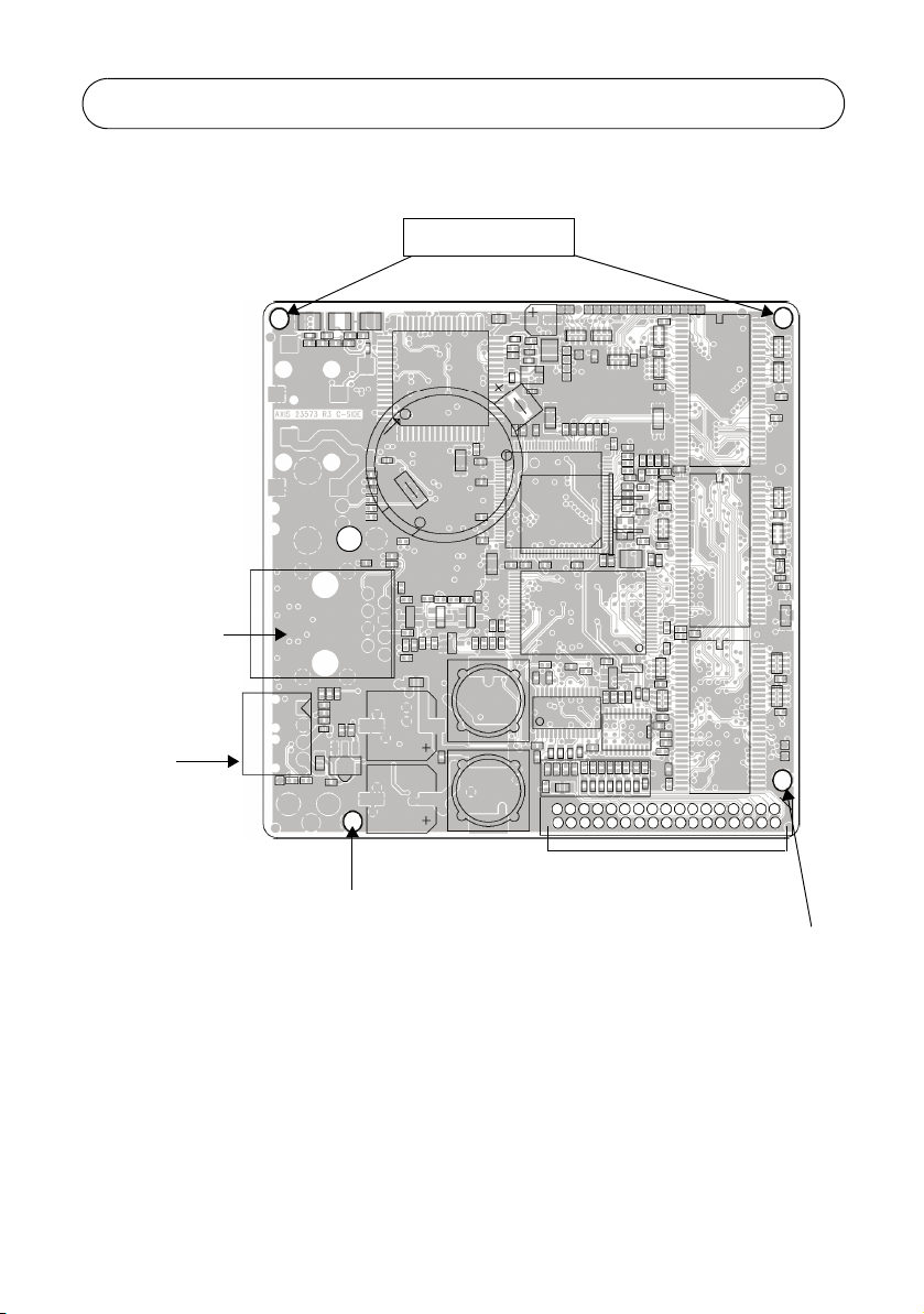
AXIS 282/282A Top
Mounting holes
Network
connector
Terminal I/O
connector
Mounting hole
Not included:
•4 M2 screws - needed for mounting AXIS 282/282A
•34 pin IDC female connector (2mm)
34-pin header
Mounting hole
Page 5

AXIS 282/282A Installation Guide Page 3
The Terminal I/O Connector
The AXIS 282/282A provides one 4-pin terminal I/O connector.
Pin Function
1 Power in/out (8 - 20V)
2GND
3Alarm In
4Alarm Out
Note: Pins 3 and 4 in the Terminal I/O Connector are the same Alarm In and Alarm Out as pins 8 and 9 in
the 34-Pin Header.
If the AXIS 282/282A has been configured to have power going in
through the 34 I/O pins, power can be configured to go out through pin 1
of the Terminal I/O Connector.
Schematic Diagram - Terminal I/O Connector
123 4
Network connector
The AXIS 282/282A connects to the network via a standard STP network
cable, and automatically detects the speed of the local network segment
(Ethernet 10BaseT/100BaseTX, RJ-45).
Page 6

Page 4 AXIS 282/282A Installation Guide
The 34-Pin Header
The AXIS 282/282A has a 34-Pin Header to be used with a 2mm IDC connector.
Connections include:
•Serial port, configurable as RS-232 or RS-485, which is typically used for connecting Pan/Tilt/Zoom devices.
•Video in and out connections
•Audio in and out connections
•LED outputs
•DC power auxiliary connection point
Pin Function Pin Function
1 Network LED green 2 Network LED red
3 Status LED green 4 Status LED red
5 Flash LED 6 Power LED
7 Control button 8 Alarm In
9 Alarm Out 10 Ground
11 Y/C Video in (Y) 12 Y/C GND
13 Y/C Video in (C) 14 Y/C GND
15 Composite Video In 16 Composite Video Source
GND
17 •AXIS 282: Not used
•AXIS 282A MIC/Line in
19 •AXIS 282: Not used
•AXIS 282A Audio/Line out
21 RS-485 B 22 RS-485 A
23 Serial port RTS (RS-232) 24 Serial port CTS (RS-232)
25 Serial port TXD (RS-232) 26 Serial port RXD (RS-232)
27 Serial port GND 28 Power GND
29 Power GND 30 Power I/O
31 Power GND 32 Power IN
33 Power IN 34 Power IN
18 Mic/Line in GND
20 Line Out GND
Page 7

AXIS 282/282A Installation Guide Page 5
Schematic Diagram - 34 I/O Pins
Note: Pins 8 and 9 in the 34-Pin Connector
are the same Alarm In and Alarm Out
as pins 3 and 4 in the Terminal I/O Connector.
Page 8

Page 6 AXIS 282/282A Installation Guide
AXIS 282/282A Bottom
Power LED
Network LED
Status LED
Control button
Flash button
LED indicators - See AXIS 282/282A User’s Manual for a complete
listing of the status of the colored Status, Network, and Power
indicators.
Control button - Used to restore the factory default settings, as
described in AXIS 282/282A User’s Manual.
Flash button - The AXIS 282/282A has a flash button. Used only for
firmware programming in the factory and not when upgrading the
firmware! See AXIS 282/282A User’s Manual for more information.
Page 9

AXIS 282/282A Installation Guide Page 7
Integration of the AXIS 282/282A
Mechanical integration may be done through the 4 mounting holes on the
AXIS 282/282A, shown in the figure below. Electrical integration of the
AXIS 282/282A is done through the connectors described here.
Mounting holes
Mounting holes
Network Connector
Control button
19mm
Flash button
Page 10

Page 8 AXIS 282/282A Installation Guide
Technical Specifications
Item Specification
Models • AXIS AXIS 282: 1-channel bare board video server
• AXIS AXIS 282A: 1-channel bare board video server with two-way audio
Audio features
AXIS 282A only
Connectors • One 34-pin I/O header
Power • Via pin 3 of the Terminal Block: 8 - 20V DC, max 8W
Operating
conditions
Installation,
management
and
maintenance
Approvals • AXIS 282/AXIS 282A is delivered as a component for the sole purpose of
Dimensions • HxWxD = 19 x 79 x 82mm (3/4” x 3 1/8” x 3 1/4”)
• G.711 PCM 64kbit/s, G.726 ADPCM 32 or 24 kbit/s, full duplex, half
duplex, simplex or audio off
- 1 analog composite or Y/C video input (NTSC/PAL autosensing )
- RS-485 or RS-232 port
- 1 alarm input, 1 alarm output
- Power connection (input and output)
- LED outputs
- Audio input (282A): Microphone (54 mVpp) or Line in (8.0 Vpp),
mono
- Audio output (282A): Line out (2.6 Vpp), mono
• Terminal block:
- 1 alarm input, 1 alarm output
- Alternative power connection
• Ethernet 10Base/100BaseTX,RJ-45 connector
• Via pins 32 - 34 of the 34-pin header: 8 -20V DC, max 8W
o
• Temperature: 5
• Humidity: 20-80% RH (non-condensing)
User’s manual and installation tool available at www.axis.com
Web-based configuration, Configuration backup and restore Firmware
upgrades over HTTP or FTP, firmware available at www.axis.com
being integrated into a product or system. The foregoing implies an
obligation on behalf of the integrator to obtain any approvals from
authorities or governmental bodies that may be required for the lawful
use of the finished product or system, which includes the
AXIS 282/AXIS 282A as a component. Resale and use of the AXIS 282/
AXIS 282A on a stand-alone basis is not allowed.
• Weight: 60g (2 1/8oz)
C (41oF) to 50oC (122oF)
For a complete detailed description of technical specifications see the AXIS
282/282A Bare Board Video Server User’s Manual.
Page 11

Page 12

AXIS 282/282A Installation Guide v1.0 August 2006
Copyright © Axis Communications AB, 2006 Part No. 27335
 Loading...