

Page 1
Installation Instructions
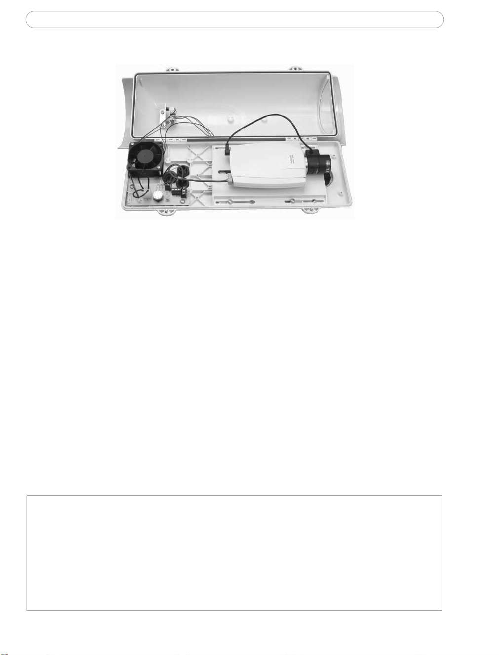
This document is an addendum to the Camera Housing Operating Instructions and
describes how to connect power to a Axis network camera installed in the housing. Please
read through both instructions before proceeding with the installation.
This description applies to the following articles:
Product Description Part number
• Verso Cool Outdoor Housing, HPV42K0A017 Housing 0217-141
• VT Outdoor Power Supply OHEGBPS1B Power supply 0217-151
• VT Heater 110/230VAC OHPVH1 Heater 0217-161
• 230V cable Power cable not supplied
• 12V cable Power cable (min. area 0.5mm2) not supplied
• AXIS 210/210A/211/211A Network Camera
•AXIS 221 Network Camera
Important!
High voltage - the apparatus works on 230V AC. Always ensure that the power is disconnected before starting any work or opening the housing.
This product should be installed by certified electrical technicians in compliance with local
laws and regulations.
Use cable glands and/or cables that are suitable for external use and are in compliance with
local laws and regulations.
Page 2
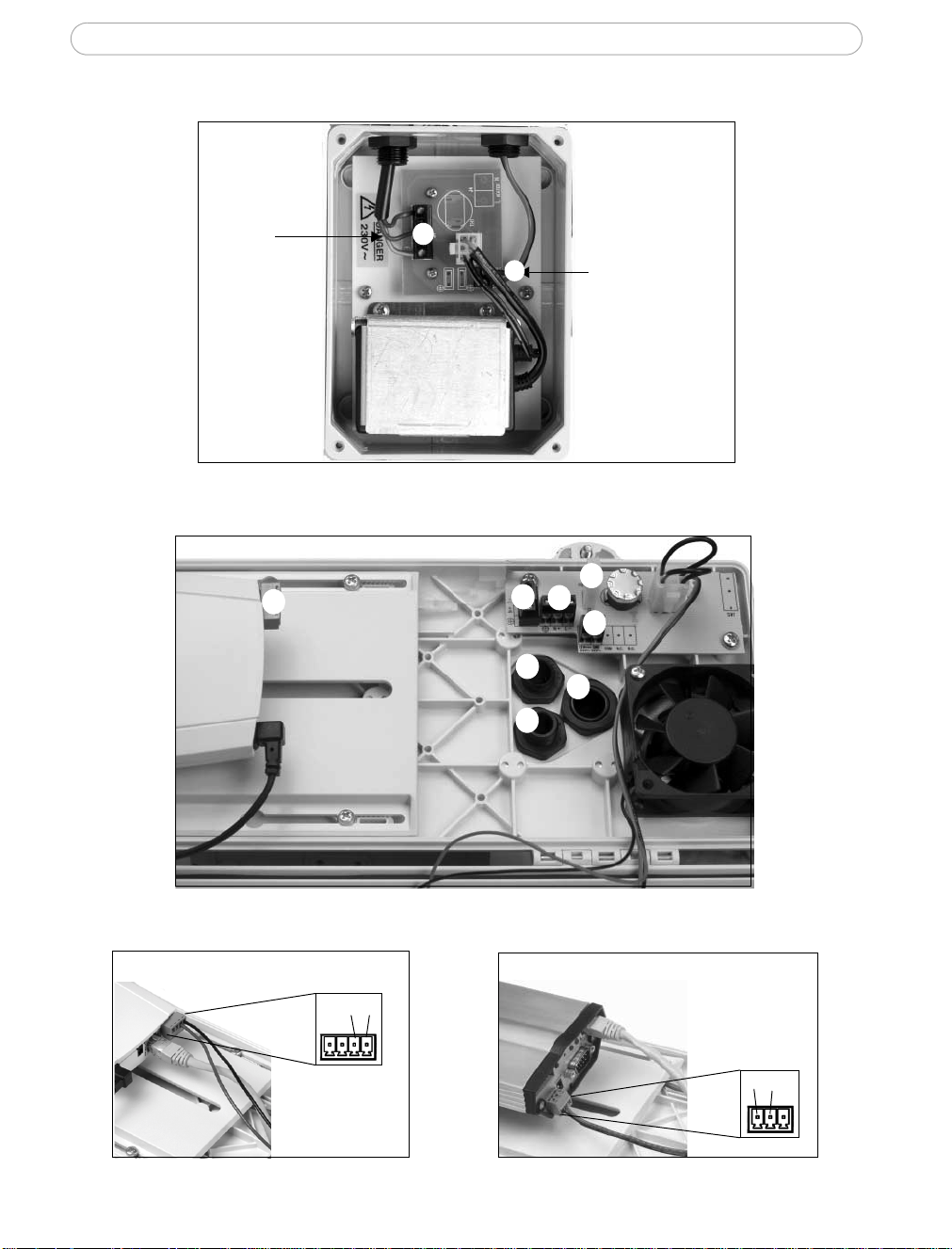
Power supply connectors
Installation Instructions
Mains power
cable
Housing connectors
8
A
B
J4
5
7
12V power cable
to housing/camera
J2
J3
J1
6
Camera connectors (8)
AXIS 210/210A/211/211A
AXIS 221
(+)(-)
(-)(+)
Page 3

Installation Instructions
Powering the Axis network camera, housing and heater
Note - this installation requires 2 x 230V power cables and 2 x 12V cables (not supplied).
1. Pull the mains power cable through the gland (5) to the housing connector (J4).
2. Connect a 230V cable to the housing connector (J3) and pull through the gland (6).
Connect to the external power supply connector (A).
3. Connect a 12V power cable to the connector (B) in the power supply, pull the 12V cable
through the gland (7) in the housing and connect to the 12V connector (J1).
4. Connect a 12V cable from the connector (J1) to the green connector on the camera (8).
Important! Ensure that the (+) and (-) wires are connected according to the camera
model installed in the housing (see images above).
5. To connect the heat er, follow the supplied instructions and connect the cable to the
connector (J2) in the housing.
6. Proceed with the installation according to the instructions in the Installation Guide
supplied with the camera.
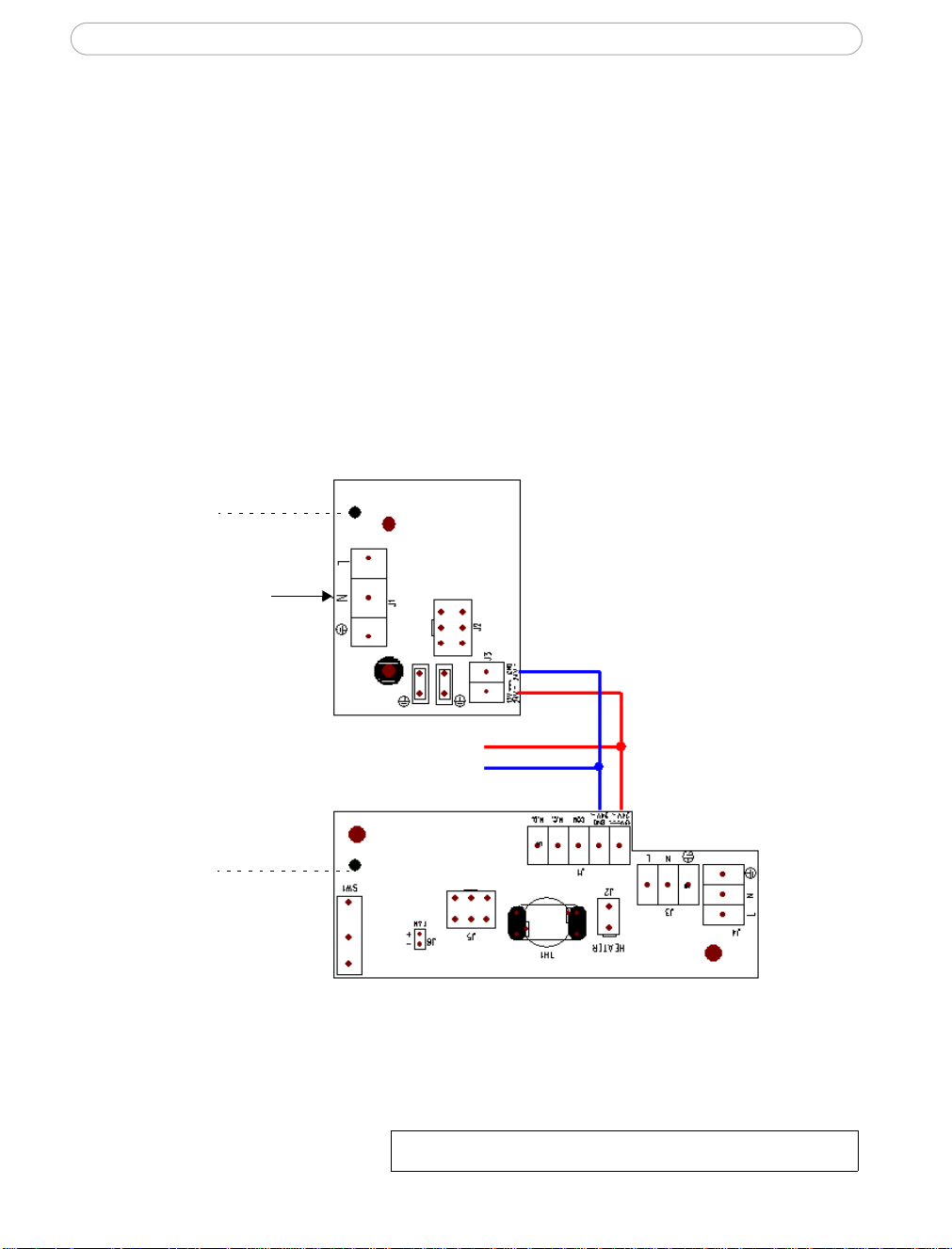
Wiring diagram
PCB
Power supply
230V AC in
PCB
Housing
12V DC
to camera
230V AC
out
230V AC
in
Heater 230V AC
Page 4
Installation Instructions
Powering the Axis network camera and housing (no heater)
Note - this installation requires one 230V power cable and 2 x 12V cables (not supplied).
1. Connect the mains power cable to the connector (A) in the power supply.
2. Connect a 12V power cable to the connector (B) in the power supply , pull the 12V cable
through the gland (6) in the housing and connect to the 12V connector (J1).
3. Connect a 12V cable from the connector (J1) to the green connector on the camera (8).
Important! Ensure that the (+) and (-) wires are connected according to the camera
model installed in the housing (see images above).
Proceed with the installation according to the instructions in the Installation Guide
supplied with the camera.
Wiring diagram
PCB
Power supply
230V AC in
PCB
Housing
12V DC
to camera
INSTALL GUIDE VT HOUSING FAN R1.0 PART NO. 25254
Date: July 2005 COPYRIGHT AXIS COMMUNICATIONS AB 2005
 Loading...