

Page 1

ESP-4 MI
Serial Hub
Installer/User Guide
Page 2
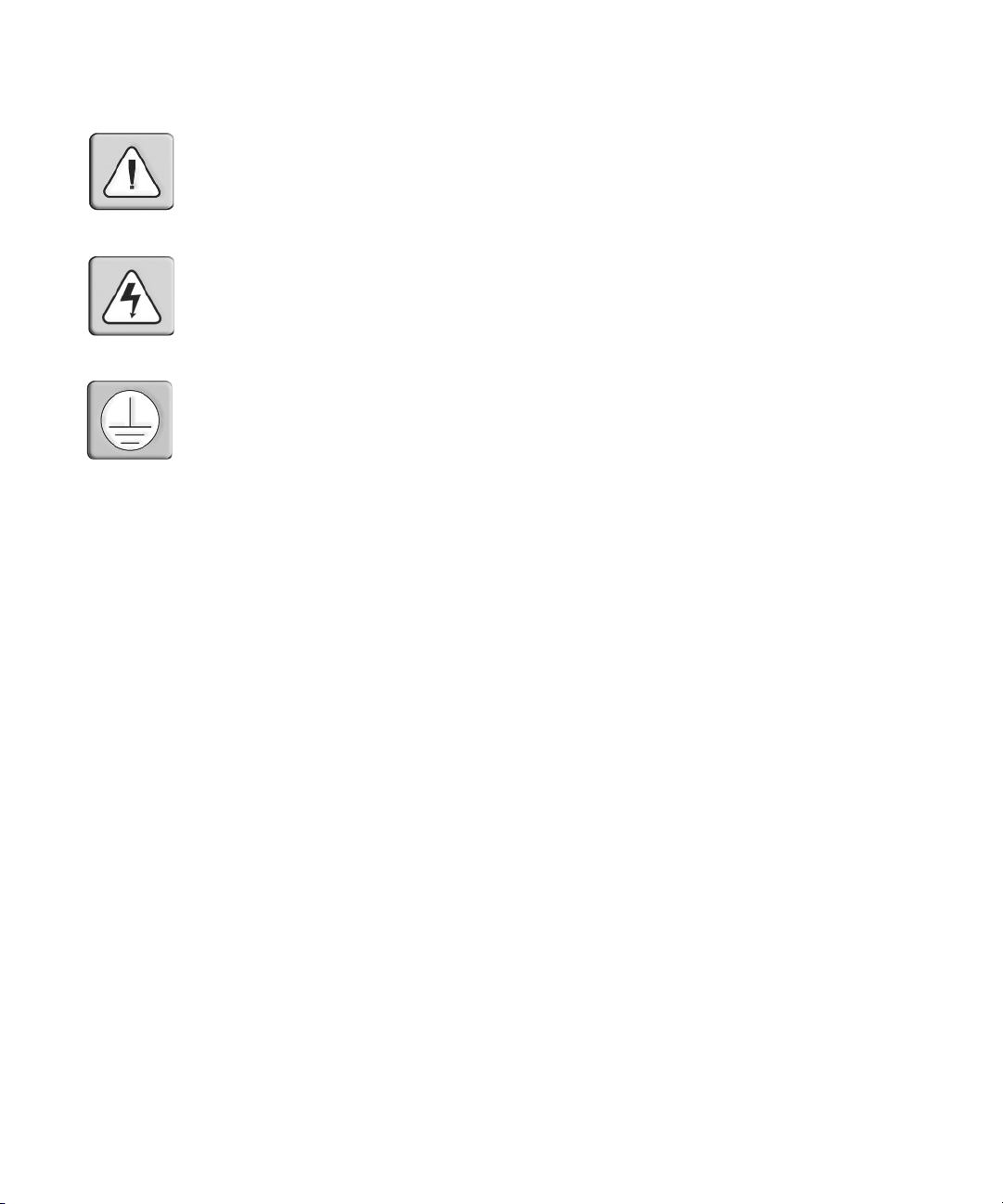
INSTRUCTIONS
This symbol is intended to alert the user to the presence of important operating and
maintenance (servicing) instructions in the literature accompanying the appliance.
DANGEROUS VOLTAGE
This symbol is intended to alert the user to the presence of uninsulated
dangerous voltage within the product’s enclosure that may be of sufficient
magnitude to constitute a risk of electric shock to persons.
PROTECTIVE GROUNDING TERMINAL
This symbol indicates a terminal which must be connected to earth ground
prior to making any other connections to the equipment.
Page 3

ESP-4 MI Serial Hub
Installer/User Guide
Avocent, the Avocent logo and The Power of Being There are registered
trademarks of Avocent Corporation or its affiliates. All other marks are
the property of their respective owners.
© 2005 Avocent Corporation. All rights reserved. 590-524-501A
Page 4

USA Notification
WARNING: Changes or modifications to this unit not expressly approved by the party responsible for compliance could void the user’s authority to operate the equipment.
NOTE: This equipment has been tested and found to comply with the limits for a Class A digital device, pursuant to Part 15 of the FCC rules. These limits are designed to provide reasonable protection against harmful
interference when the equipment is operated in a commercial environment. This equipment generates, uses,
and can radiate radio frequency energy and, if not installed and used in accordance with the instruction manual, may cause harmful interference to radio communications. Operation of this equipment in the residential
area is likely to cause harmful interference in which case the user will be required to correct the interference at
his own expense.
Canadian Notification
This digital apparatus does not exceed the Class A limits for radio noise emissions from digital apparatus set
out in the Radio Interference Regulations of the Canadian Department of Communications.
Le présent appareil numérique n’émet pas de bruits radioélectriques dépassant les limites applicables aux
appareils numériques de la classe A prescrites dans le Règlement sur le brouillage radioélectrique édicté par le
Ministère des Communications du Canada.
European Union
WARNING: This is a Class A product. In domestic environment, this product may cause radio interference in
which case the user may be required to take adequate measures.
Page 5

TABLE OF CONTENTS
Table of Contents
List of Tables..................................................................................................................vii
Chapter 1: Introduction ................................................................................................... 1
Features .............................................................................................................................................1
Chapter 2: Hardware Installation and Network Configuration..................................... 3
ESP-4 MI Hub Kit Contents...............................................................................................................3
Hardware Overview...........................................................................................................................3
Physical interfaces............................................................ ..........................................................4
Network interface........................................................................................................................4
Pin Assignments.................................................................................................................................5
Serial ports .......................... .......................................................................................................5
Adaptors......................................................................................................................................6
Ethernet connector.................................................................................. ....................................7
Electrical............................................................................................................................................8
Installing the Hub ..............................................................................................................................8
Startup................................................................................................................................................8
Configuring Network Information.....................................................................................................8
After startup and address configuration.....................................................................................9
When Changes Take Effect ................................................................................................................9
Reinitializing and Resetting the Hub...............................................................................................10
Reinitializing.............................................................................................................................10
Resetting ...................................................................................................................................10
iii
Chapter 3: Connection Methods, Attributes and Configurable Features................. 11
Serial Port Connection Methods.............................................. ... .....................................................11
Serial port redirection .......................................... ...................................................... ..............12
Telnet server .............................................................................................................................12
Raw TCP server........................................................................................................................13
Raw TCP client.........................................................................................................................14
Modem emulation .....................................................................................................................16
Configuration utility .................................................................................................................22
Serial Port Attributes.......................................................................................................................22
Page 6

iv ESP-4 MI Serial Hub Installer/User Guide
Configurable Features.....................................................................................................................23
Chapter 4: Web Interface............................................................................................... 25
Accessing the Web Interface............................................................................................................25
Passwords........................................................................................................................................26
Displaying or Changing Network Configuration Values ................................................................26
Displaying or Changing Serial Port Interface, Attributes and Connection Methods .....................27
Sending a Break to a Port ................................................................................................................28
Displaying Hardware Information ..................................................................................................28
Displaying or Updating Flash Memory...........................................................................................29
Displaying or Changing Configurable Features............................................................................. 30
Downloading a Configuration File.......................................... ........................................................30
Launching the ESP-View Diagnostic Utility ........................... ..................................................... ...30
Displaying General Statistics ..........................................................................................................31
Displaying Port Statistics ................................................................................................................31
Displaying Connection Status..........................................................................................................32
Rebooting the Hub ...........................................................................................................................33
Reinitializing the Hub............................ ...................................................... ....................................34
Chapter 5: Configuration Utility.................................................................................... 35
Accessing the Configuration Utility.................................................................................................35
Accessing with Telnet ...............................................................................................................35
Accessing a hub with no configured IP address.......................................................................36
Accessing on a port using the configuration utility connection method...................................36
About the Configuration Utility Interface ................................................................................36
Passwords........................................................................................................................................37
Displaying or Changing Network Configuration Values ................................................................37
Displaying or Changing Port Interface, Attributes and Connection Methods................................38
Sending a Break to a Port ................................................................................................................39
Displaying Hardware Information ..................................................................................................40
Displaying or Updating Flash Memory...........................................................................................40
Displaying or Changing Configurable Features............................................................................. 41
Downloading a Configuration File.......................................... ........................................................41
Rebooting the Hub ...........................................................................................................................42
Reinitializing the Hub............................ ...................................................... ....................................42
Page 7

Table of Contents v
Displaying General Statistics ..........................................................................................................42
Displaying Port Statistics ................................................................................................................42
Displaying Connection Status..........................................................................................................43
Displaying and Using Debug Features ...........................................................................................43
Chapter 6: Configuration Files...................................................................................... 45
Sample Configuration File...............................................................................................................45
File Format and Command Syntax..................................................................................................46
Port Interface Command .................................................................................................................47
Port Connection Method Commands...............................................................................................47
Port Redirection command.......................................................................................................47
Port Telnet Server command....................................................................................................47
Port TCP Server command.......................................................................................................47
Port TCP Client command .......................................................................................................47
Port Modem Emulation command............................................................................................48
Dialout Translation command..................................................................................................48
Port Configuration Utility command........................................................................................48
Port Attributes Command................................................................................................................48
Network Command ..........................................................................................................................48
Configurable Features Commands..................................................................................................49
Initiating a Configuration File Download.......................................................................................49
Completion Status............................................................................................................................49
Appendices..................................................................................................................... 51
Appendix A: Technical Specifications .............................................................................................51
Appendix B: ESP-View Diagnostic Utility.......................................................................................52
Appendix C: ESP-Install Program ..................................................................................................58
Appendix D: Technical Support.......................................................................................................64
Index................................................................................................................................ 65
Page 8

vi ESP-4 MI Serial Hub Installer/User Guide
Page 9

LIST OF TABLES
List of Tables
Table 2.1: LEDs and Buttons.............................................................................................................3
Table 2.2: RS-232 Serial Port Pin Assignments................................................................................5
Table 2.3: RS-422 and RS-485 Serial Port Pin Assignments ............................................................5
Table 2.4: RS-422 CAT 5 Adaptor Pin Assignments .........................................................................6
Table 2.5: RS-485 CAT 5 Adaptor Pin Assignments .........................................................................7
Table 2.6: Ethernet Connector Pin Assignments...............................................................................7
Table 2.7: When Changes Take Effect.............................................................................................10
Table 3.1: Serial Port Redirection Configurable Items...................................................................12
Table 3.2: Telnet Server Connection Method Configurable Items..................................................13
Table 3.3: Raw TCP Server Connection Method Configurable Items ................................. ... ........14
Table 3.4: Raw TCP Client Connection Method Configurable Items.............................................15
Table 3.5: Modem Emulation Connection Method Configurable Items .........................................16
vii
Table 3.6: Modem Commands............... ...................................................... .. ..................................18
Table 3.7: Modem Command Response Codes ...............................................................................20
Table 3.8: Dialout Translation Set .................................................................................................. 21
Table 3.9: Configuration Utility Connection Method Configurable Items .....................................22
Table 3.10: Serial Port Valid and Default Values...........................................................................23
Table 3.11: Configurable Features .................................................................................................23
Table 4.1: Reference to Connection Method Rules and Values ...................................................... 28
Table 4.2: General Statistics Display..............................................................................................31
Table 4.3: Port Statistics Display....................................................................................................31
Table 4.4: Serial Port Active Connection Status Display................................................................32
Table 4.5: Serial Port Redirection Connections Status Display .....................................................33
Table 5.1: Reference to Connection Method Rules and Values ...................................................... 39
Table 6.1: Configurable Features Commands ................................................................................49
Table A.1: ESP-4 MI Serial Hub Technical Specifications.............................................................51
Page 10

viii ESP-4 MI Serial Hub Installer/User Guide
Table B.1: ESP-View Utility Datascope Window Buttons...............................................................53
Table B.2: ESP-View Utility Status Display....................................................................................56
Table C.1: ESP-Install Program Commands ..................................................................................61
Page 11

CHAPTER
1
Features
The ESP 4-port Multi-Interface (ESP-4 MI) serial hub contains an autosensing 10/100 Ethernet
port and four multi-interface serial ports. Each port may be configured to use the RS-232, RS-422
or RS-485 interface.
Modular adaptors are available to facilitate the connection between the ESP-4 MI serial hub and the
target devices.
The ESP-4 MI hub uses an external power supply, which is provided with the hub. See Electrical
on page 8 for more information.
Serial port access
1
Introduction
All ESP-4 MI hubs support several ways to access the serial ports. Each of these connection
methods is described in Chapter 3, beginning on page 11.
• Serial port redirection
• Telnet server
• Raw TCP server
• Raw TCP client
• Modem emulation
• Configuration utility
Serial port redirection uses drivers installed on a host computer. The ESP-4 MI serial hub drivers
are supported on the following operating systems:
Windows
Windows NT
OpenServer™ 5.0.5a or higher UnixWare
Linux
Sun
For serial port redirection, the ESP-4 MI hub is configured using the appropriate drivers running on
any Microsoft Windows host, or espdiag and espcfg for OpenServer, UnixWare, Linux, Sun or
AIX systems. Certain configuration values are set during driver installation.
®
2000 Windows XP
®
4.0 Windows Server 2003
®
®
Solaris™ for X86 or SPARC 8 or higher
AIX
®
7.0.1a or higher
®
4.3 and 5.1/5.2
Page 12

2 ESP-4 MI Serial Hub Installer/User Guide
All other connection methods do not require the use of drivers.
The file-driven ESP-Install program may be used to install, modify and remove Windows drivers
for ESP Ethernet serial hubs without need for on-site technical personnel. See ESP-Install Program
on page 58.
Management tools
You may configure and/or manage the ESP-4 MI serial hub using the following tools:
• Web interface - see Chapter 4, beginning on page 25
• Configuration utility - see Chapter 5, beginning on page 35
• Configuration files - see Chapter 6, beginning on page 45
• Unix system utilities espcfg and espdiag (Unix systems) - these utilities have limited support
for connection methods other than port redirection
• Socket Application Program Interface (API)
The web interface and the configuration utility offer the most comprehensive sets of
available operations.
Using the web interface, you may launch the ESP-View diagnostic utility that provides datascope,
loopback and status functions. See ESP-View Diagnostic Utility on page 52. The configuration
utility also supports diagnostic features; see Displaying and Using Debug Features on page 43.
The ESP-4 MI hub supports attended and unattended configuration. With attended configuration,
you set values and request actions directly through the web interface or the configuration utility.
Unattended configuration uses a flat text file containing configuration commands. The co mm ands
are processed as if they were requested using the web interface or the configuration utility. The
command file may be read by BootP/DHCP during initial ESP-4 MI hub configuration.
Downloading a command file may also be requested using the web interface and configuration
utility. See Configuration Files on page 45 for more information.
The ESP serial hub provides a socket API for on-the-fly serial port operations. This API is an
extension of the raw TCP interface, which allows data to be read from or written to an ESP hub
serial port. Using socket calls, an application is able to alter port settings (such as baud rate) or read
current serial control signals (such as DTR). For details on the API specification, contact Avocent
Technical Support.
Page 13

CHAPTER
3
Hardware Installation and
2
Network Configuration
ESP-4 MI Hub Kit Contents
• ESP-4 MI serial hub.
• External power supply (PS) with attached PS-to-unit barrel connector. The line cord for the
power supply is appropriate to the intended country of operation.
• SuperSerial CD-ROM.
Modular adaptors are available from Avocent that allow a serial CAT 5 straight-through cable to
mate with the connector on the TD. See Adaptors on page 6.
Modular adaptors are also available for the modem emulation connection method. Contact Avocent
Technical Support for details.
Hardware Overview
All connectors, LEDs and buttons are on the front of the ESP-4 MI serial hub.
The lower left corner of the front panel contains the electrical connector. For more information, see
Electrical on page 8.
The Ethernet port supports 10/100 auto detect (speed and duplex) connections. The LAN connector
accepts 10BaseT or 100BaseT LAN interface cable. A CAT 5 cable is required for 100BaseT
operation. Table 2.6 on page 7 lists the pin assignments. See Network interface on page 4 for
information about configuring the network interface.
The PORT 1, 2, 3 and 4 connectors are standard DB-9 DTE ports in RS-232 mode. Table 2.2 on
page 5 lists the pin assignments for each interface. The unit ships with RS-422 mode enabled for
all ports.
Table 2.1 describes the LEDs and buttons on the front panel.
Table 2.1: LEDs and Buttons
Item Description
POWER The POWER LED is lit when the hub is connected to a power source.
ON LINE
The ON LINE LED is lit (not blinking) when the hub’s self-test and initialization procedures
have completed successfully.
Page 14

4 ESP-4 MI Serial Hub Installer/User Guide
Table 2.1: LEDs and Buttons (Continued)
Item Description
10
100
RESET Pushing the RESET button reboots the hub; see Resetting on page 10.
INIT
Physical interfaces
Each port supports the standard RS-232 DTE serial signals using a male DB-9 connector, with the
exception of RI (Ring Indicator).
Each serial port may be configured to support the following interfaces:
• RS-232 DTE signaling.
• RS-422 signaling (default).
• RS-485 2-wire half duplex (HD) signaling. This interface uses ADDC (Automatic Data Detec-
tion Control) mode. The transmitter is enabled and the receiver is disabled when a space (zero)
bit is sent. The transmitter is disabled and the receiver is enabled when a mark (one) is sent.
This allows rapid turnaround and release of the data pair.
When the RS-422 or RS-485 interface is enabled for a port, you may also enable/disable 100 ohm
termination of the differential receive signal pair on that port. This termination is typically used in
RS-485 environments when the device is the first or last on a multi-drop line for a 2-wire
configuration. This termination should always be set when the unit is configured for RS-422, as this
is a point-to-point configuration.
If your configuration includes supplying your own external termination, the termination on the
ESP-4 MI hub should not be used.
The 10 LED is lit when the hub is connected to a 10 Mbps LAN, and the 100 LED blinks
when traffic is present.
The 100 LED is lit when the hub is connected to a 100 Mbps LAN, and the 10 LED blinks
when traffic is present.
Pushing and holding the INIT button restores the hub to factory defaults; see Reinitializing
on page 10.
Network interface
The network interface speed may be configured with the following values.
Auto-negotiate
10 Mb/second half or full duplex 100 Mb/second half or full duplex
10 Mb/second half duplex 100 Mb/second half duplex
10 Mb/second full duplex 100 Mb/second full duplex
By default, auto-negotiate and all settings are enabled. The setting that will be used is determined
by which settings are available and also by priority. For a standard CAT 5 twisted pair cable, the
priority is (from highest to lowest):
Page 15

100 Mb/second, full duplex
100 Mb/second, half duplex
10 Mb/second, full duplex
10 Mb/second, half duplex
Pin Assignments
This section lists the pin assignments for the serial ports, available adaptors and the ESP-4 MI
serial hub Ethernet connector.
Serial ports
Table 2.2 lists the pin assignments for the RS-232 interface. This information is also provided on a
label on the bottom of the hub.
Table 2.2: RS-232 Serial Port Pin Assignments
Pin Number RS-232 Description Direction
1 DCD Data Carrier Detect Input
2 RxD Receive Data Input
3 TxD Transmit Data Output
4 DTR Data Terminal Ready Output
Chapter 2: Hardware Installation and Network Configuration 5
5 GND Ground N/A
6 DSR Data Set Ready Input
7 RTS Request to Send Output
8 CTS Clear to Send Input
9 N/C N/C N/A
Not supported: RI, RS-422 RTS and CTS differential control signals.
Unused pins (labeled N/C) should not have wires attached to t hem. Floating wires could cau se unba la nced
noise, shorten overall distances and degradeperformance.
Table 2.3 lists the pin assignments for the RS-422 and RS-485 interfaces.
Table 2.3: RS-422 and RS-485 Serial Port Pin Assignments
Pin Number RS-422/485 * Description Direction
1 RxD (+) Receive Data (pos) Input
2 RxD (-) Receive Data (neg) Input
3 TxD (+) Transmit Data (pos) Output
Page 16

6 ESP-4 MI Serial Hub Installer/User Guide
Table 2.3: RS-422 and RS-485 Serial Port Pin Assignments (Continued)
Pin Number RS-422/485 * Description Direction
4 TxD (-) Transmit Data (neg) Output
5 GND Ground N/A
6 DSR (RS-232) Data Set Ready (remains RS-232) Input
7 RTS * (RS-232) Request to Send (remains RS-232) * Output
8 CTS * (RS-232) Clear to Send (remains RS-232) * Input
9 N/C N/A N/A
* The RS-485 interface is implemented by using special cables that connect RxD(+) to TxD(+) and RxD(-) to
TxD(-), thus providing the 2-wire bidirectional interface. In addition, pins 7 and 8 should be jumpered together
to signal that the port is configured for RS-485. Pins 7 and 8 should be left open for an RS-422 configuration.
Adaptors
Two adaptors are available from Avocent to enable use of standard CAT 5 cable twisted pairs for
RS-422 receive and transmit signals, plus one of the pairs for the RS-485 signal pair.
Table 2.4 lists the pin assignments for the RS-422 CAT 5 adaptor.
Table 2.4: RS-422 CAT 5 Adaptor Pin Assignments
Pin Number - DB-9 RS-422 Description Pin Number - RJ-45
1 RxD (+) Receive Data (pos) 1
2 RxD (-) Receive Data (neg) 2
3 TxD (+) Transmit Data (pos) 4
4 TxD (-) Transmit Data (neg) 5
5 GND Ground N/C
6 DSR (RS-232) Data Set Ready N/C
7 RTS (RS-232) Request to Send N/C
8 CTS (RS-232) Clear to Send N/C
9 N/C N/A N/C
Page 17

Chapter 2: Hardware Installation and Network Configuration 7
Table 2.5 lists the pin assignments for the RS-485 CAT 5 adaptor.
Table 2.5: RS-485 CAT 5 Adaptor Pin Assignments
Pin Number - DB-9 RS-422 Description Pin Number - RJ-45
1 RxD (+) Receive Data (pos) 4
2 RxD (-) Receive Data (neg) 5
3 TxD (+) Transmit Data (pos) 4
4 TxD (-) Transmit Data (neg) 5
5 GND Ground N/C
6 DSR (RS-232) Data Set Ready N/C
7 RTS (RS-232) * Request to Send N/C
8 CTS (RS-232) * Clear to Send N/C
9 N/C N/A N/C
RxD(+) and TxD(+) are both connected to pin 4 of the RJ-45 connector.
RxD(-) and TxD(-) are both connected to pin 5 of the RJ-45 connector.
* RTS is tied to CTS inside the adaptor to indicate an RS-485 connection.
Ethernet connector
Table 2.6 lists the pin assignments for the RJ-45 shielded Ethernet connector.
Table 2.6: Ethernet Connector Pin Assignments
Pin Signal
1 Transmit Data +
2 Transmit Data 3 Receive Data +
4*
5*
6 Receive Data 7*
8*
* These pins are usually connected in a standard Ethernet CA T 5 cable. There is special termination for these
signals in the interface to eliminate any problems if they are connected.
Page 18

8 ESP-4 MI Serial Hub Installer/User Guide
Electrical
The ESP-4 MI serial hub uses a Universal 5 VDC power supply. This external supply, which must
be provided by Avocent, has a standard IEC AC input connector that accepts power cords for USA
and international power connections.
Surge protection is provided for every signal on each serial port and meets or exceeds the
applicable European CE Immunity Standards.
Installing the Hub
The ESP-4 MI hub ships ready to use in a tabletop environment, with four rubber feet on the
bottom of the hub.
NOTE: The power outlet should be near the equipment and be easily accessible.
You may replace an existing ESP-4 MI hub with a similarly configured hub without affecting the
server or having to reconfigure the ports.
Startup
To initiate the startup sequence:
1. The MAC address is printed on a label on the hub. This address is used as a Unit ID to
distinguish different ESP hubs on the network. Record the MAC address.
00 - E0 - 86 - _____ - _____ - _____
2. Attach a 10BaseT or 100BaseT LAN interface cable to the LAN connector on the front of the
hub. A CAT 5 cable is required for 100BaseT operation. Then, attach the other end of the LAN
interface cable to the Ethernet hub or switch.
3. Connect devices to the serial ports on the front of the hub, using appropriate cables (and
adaptors, if needed).
4. Plug the barrel connector of the PS into the front of the hub, then attach the line cord connector
to an appropriate power s ource.
Configuring Network Information
Configuring network information includes setting the IP address, subnet mask and gateway. You
may also configure the network interface setting (see Network interface on page 4 for
more information).
To configure network information:
• Using the web interface - Y ou may initially access the hub using the predefined IP address (see
Accessing the Web Interface on page 25), then configure the network information (see
Displaying or Changing Network Configuration Values on page 26).
Page 19

Chapter 2: Hardware Installation and Network Configuration 9
• Using the configuration utility - The configuration utility is automatically enabled on port 1.
Using a terminal emulation program of your choice (with a serial connection at 19200 baud, 8
bits, no parity and one stop bit), you may access the configuration utility on this port (see
Accessing the Configuration Utility on page 35). Then, configure the network information (see
Displaying or Changing Network Configuration Values on page 37).
• Using the serial port redirection connection method - Install the ESP-4 MI drivers included on
the CD (be sure to check the Avocent web site, www.avocent.com, for the latest version).
You may also use the ESP-Install program with a script file to automate the installation; see
ESP-Install Program on page 58. The Release Notes also contain driver information.
• Using a configuration file - If you are using a configuration file with a BootP or DHCP server,
consult your operating system documentation to dete rm ine how to configure the BootP or
DHCP server.
• After the ESP-4 MI hub acquires an IP address (by any method), it will no longer use
BootP or DHCP. Therefore, you cannot change the network values using this method.
• The ESP-4 MI hub requires a permanent IP allocation. If you are using DHCP, it must
have an infinite lease on the assigned IP address; an IP address with a finite lease will not
be accepted.
The BootP or DHCP server may also specify a configuration file using the “bootfile”
parameter. See Chapter 6, beginning on page 45, for more information.
After startup and address configuration
After the ESP-4 MI serial hub’s network information has been configured, you may configure each
of the ports. This includes specifying the interface type, port attributes and supported
connection methods.
To configure ports:
• Using the web interface - see Displaying or Changing Serial Port Interface, Attributes and
Connection Methods on page 27.
• Using the configuration utility - see Displaying or Changing Port Interface, Attributes and
Connection Methods on page 38.
• Using a configuration file - see Port Interface Command on page 47, Port Connection Method
Commands on page 47 and Port Attributes Command on page 48.
When Changes Take Effect
When you change values, the ESP-4 MI serial hub’s EEPROM is updated immediately. Some
changes take effect immediately; others take effect when the next connection is established with a
port or after the hub is rebooted.
Page 20

10 ESP-4 MI Serial Hub Installer/User Guide
Table 2.7 indicates when each type of change takes effect.
Table 2.7: When Changes Take Effect
Action Immediately
Network address changes (IP, gateway, subnet) X
Network interface speed X
Enabling/disabling the hub’s configurable features X
Changing a port’s physical interface X
Enabling/disabling a port’s connection methods X
Changing a port’s attributes X
Updating a Flash image X
Downloading a configuration file X
Changing a web interface/configuration utility password takes effect the next time the web
interface or the configuration utility is accessed.
Reinitializing and Resetting the Hub
The information in this section is not a standard part of the startup sequence; however, it is
provided for reference if the serial hub must be reinitialized or reset.
Reinitializing
The INIT button on the front panel may be used to remove configured information from an ESP-4
MI hub. The hub stores nonvolatile data such as the SNMP community name, admin password,
system contact and IP address in the EEPROM. This information is erased by pressing and holding
the INIT button until reinitialization occurs.
When the INIT button is first pressed, the ON LINE LED will begin to blink to confirm that you
have pressed the INIT button. As the INIT button remains pressed, the ON LINE LED will blink at
a faster rate. After approximately 12 seconds, the ON LINE LED will turn off. At this point, all
nonvolatile information will be reset to the factory defaults and the hub will immediately reboot.
You may also reinitialize the hub using the web interface (see Reinitializing the Hub on page 34) or
the configuration utility (see Reinitializing the Hub on page 42).
On next
connection
After reboot
Resetting
The RESET button on the front panel may be used to reset the serial hub. Pushing this button will
cause an immediate reboot. You may also reset (reboot) the hub using the web interface (see
Rebooting the Hub on page 33) or the configuration utility (see Rebooting the Hub on page 42).
Page 21

CHAPTER
11
Connection Methods, Attributes
3
This chapter describes:
• Connection methods, which are configured for each of the four serial ports
• Attributes, which are configured for each of the four serial ports
• Configurable features, which are enabled/disabled for the entire serial hub
and Configurable Features
Serial Port Connection Methods
There are several methods to access a serial port on the ESP-4 MI hub.
• Serial port redirection - see page 12
• Telnet server - see page 12
• Raw TCP server - see page 13
• Raw TCP client - see page 14
• Modem emulation - see page 16
• Configuration utility - see page 22
Each connection method may be enabled or disabled for each ESP-4 MI port. A port may have
multiple connection methods enabled, with the following exceptions.
• The raw TCP client connection method is exclusive; when it is enabled on a port, no other connection methods can be enabled for that port. (Conversely, if other connection methods are
enabled for a port, you cannot enable the raw TCP client connection method on that port until
you disable the other methods.)
• If you enable the raw TCP server connection method and enable the idle TCP buffering option
on a port, then the TCP server connection method becomes exclusive; no other connection
methods can be enabled for that port.
• The modem emulation connection method is valid only on an RS-232 port. This method is
exclusive; when it is enabled on a port, no other connection methods can be enabled for
that port.
In any case, a port may be actively open and used by only one method at a time.
Page 22

12 ESP-4 MI Serial Hub Installer/User Guide
You may configure port connection methods using any of the following tools.
• Web interface - see Displaying or Changing Serial Port Interface, Attributes and
Connection Methods on page 27
• Configuration utility - see Displaying or Changing Port Interface, Attributes and
Connection Methods on page 38
• Configuration file - see Port Connection Method Commands on page 47
Serial port redirection
The serial port redirection connection method uses an ESP serial redirection driver on a host
computer to communicate with the hub. The driver creates a virtual COMM or TTY port interface
within the host’s operating system.
Table 3.1 describes this method’s configurable items for each serial port.
Table 3.1: Serial Port Redirection Configurable Items
Item Description
Enable/
disable
Serial
buffering
To use the serial port redirection connection method, you must install drivers on the host computer.
See the Release Notes on the SuperSerial CD for information. You may also use the ESP-Install
program; see ESP-Install Program on page 58.
Telnet server
The Telnet server connection method allows a user to make a Telnet connection to a serial port on
the ESP-4 MI hub and then transmit/receive data using the standard Telnet protocol. This method is
also known as reverse Telnet.
When this method is enabled, the Telnet server within the hub will accept a connection from any
valid remote IP address. There is no filtering of remote addresses. The connection will be accepted
only if the port is not already open and in use by any connection method, including an existing
Telnet session on that port. If the port is currently in use, the connection request will be rejected.
The Telnet session will remain established until the remote client ends the session, the Telnet TCP
socket is broken or the inactivity time-out (if enabled) occurs.
Enables or disables the serial port redirection connection method on the serial port. The
default value is enabled. This method cannot be enabled if the raw TCP client connection
method is already enabled for the port.
Specifies the length of time accumulated serial data should be buffered before being sent to
the remote server. Valid values are 0-65535 hundredths of a second. A 0 value indicates that
data will be sent as soon as it is available.
For example, a value of 100 indicates that once serial data is received, it will remain buffered
up to 1 second (100 hundredths of a second), at which time all data will be sent.
If the buffer becomes half full, the time is ignored and the data is sent.
The default value is 0 (send immediately).
Page 23

Chapter 3: Connection Methods, Attributes and Configurable Features 13
Table 3.2 describes this method’s configurable items for each serial port.
Table 3.2: Telnet Server Connection Method Configurable Items
Item Description
Enable/
disable
Local IP port
number
Inactivity timeout
Serial
buffering
Raw TCP server
The raw TCP server connection method allows a remote client to make a TCP socket connection to
a serial port on the ESP-4 MI hub and then transmit/receive data using standard TCP. The remote
client initiates the TCP session, using a predefined IP port number.
When this method is enabled, the TCP server will accept a connection from any valid remote IP
address. There is no filtering of remote addresses. When a remote raw TCP client attempts to
establish a connection, the raw TCP server will accept the connection only if the port is not already
open and in use by any connection method, including an existing raw TCP server connection on
that port. If the port is currently in use, the connection request will be rejected.
The TCP session will remain active until the remote client closes the TCP socket, the TCP
connection is broken or the inactivity time-out (if enabled) occurs.
Enables or disables the T elnet server connection method on the port. This method cannot be
enabled if the raw TCP client connection method is already enabled for the port.
The default value is disabled.
Specifies the IP port number on which the Telnet server will listen. This value cannot conflict
with the port numbers specified for other enabled connection methods on either port. Valid
values are 1024-65535.
The default value is 3001 for port 1, 3002 for port 2, 3003 for port 3 and 3004 for port 4.
Specifies the length of time before the Telnet session is disconnected if there is no activity.
Valid values are 0-65535 seconds. A 0 value disables the inactivity time-out.
For example, a value of 60 indicates the Telnet session will be disconnected if there is no
activity for a period of 60 seconds.
The default value is 0 (disabled).
Specifies the length of time accumulated serial data should be buffered before being sent
across the network to the Telnet client. Valid values are 0-65535 hundredths of a second. A 0
value indicates that data will be sent as soon as it is available.
For example, a value of 100 indicates that once serial data is received, it will remain buffered
up to 1 second (100 hundredths of a second), at which time all data will be sent.
If the buffer becomes half full, the time is ignored and the data is sent.
The default value is 0 (send immediately).
Page 24

14 ESP-4 MI Serial Hub Installer/User Guide
Table 3.3 describes this method’s configurable items for each serial port.
Table 3.3: Raw TCP Server Connection Method Configurable Items
Item Description
Enable/
disable
Local IP port
number
Inactivity timeout
Monitor DCD
Serial
buffering
Enables or disables the raw TCP server connection method on the port. This method cannot
be enabled if the raw TCP client connection method is already enabled for the port.
The default value is disabled.
Specifies the IP port number on which the TCP server will listen. This value cannot conflict
with port numbers specified for other enabled connection methods on other ports. Valid
values are 1024-65535.
The default value is 4001 for port 1, 4002 for port 2, 4003 for port 3 and 4004 for port 4.
Specifies the length of time before the TCP session is disconnected if there is no activity.
Valid values are 0-65535 seconds. A 0 value disables the inactivity time-out.
For example, a value of 60 indicates the TCP session will be disconnected if there is no
activity for a period of 60 seconds.
The default value is 0 (disabled).
(Valid only on RS-232 ports.) Enables or disables monitoring of the DCD signal, which is an
indication that a serial device is attached and powered on. When enabled, the TCP server will
refuse the TCP connection if the inbound DCD signal is logically low at the time the
connection is initiated. If the inbound DCD signal changes from logically high to low while a
TCP session is active, the TCP connection will be closed.
The default value is disabled.
Specifies the length of time accumulated serial data should be buffered before being sent to
the remote server. Valid values are 0-65535 hundredths of a second. A 0 value indicates that
data will be sent as soon as it is available.
For example, a value of 100 indicates that once serial data is received, it will remain buffered
up to 1 second (100 hundredths of a second), at which time all data will be sent.
If the buffer becomes half full, the time is ignored and the data is sent.
The default value is 0 (send immediately).
Idle TCP
buffering
Raw TCP client
The raw TCP client connection method allows the ESP-4 MI hub to make a TCP-based connection
to a remote server and then transmit/receive data using standard TCP. The client hub initiates the
TCP session.
When this method is enabled, the raw TCP client will attempt to establish a connection with the
configured server when the connection mode requirement has been satisfied. The TCP session will
remain active until the client closes the TCP socket, the TCP connection is broken, the inactivity
Enables or disables buffering of received serial data while waiting for a TCP connection to be
established. When enabled, the most recent 20K bytes of data are held in an internal buffer.
After the connection is established, the buffered serial data is sent to the TCP client. When
this option and this connection method are enabled, you may not enable any other connection
method for the port.
The default value is disabled.
Page 25

Chapter 3: Connection Methods, Attributes and Configurable Features 15
time-out (if enabled) occurs or if the connection mode is Connect on DCD and the DCD signal
is lowered.
Table 3.4 describes this method’s configurable items for each serial port.
Table 3.4: Raw TCP Client Connection Method Configurable Items
Item Description
Enable/
disable
Destination IP
address
Destination IP
port number
Local IP port
number
Inactivity timeout
Connection
mode
Serial
buffering
Enables or disables the raw TCP client connection method on the port. This method cannot
be enabled if any other serial port connection method is already enabled on the port.
The default value is disabled.
Specifies the IP address of the raw TCP server. This is a required item; there is no default
value. Only a single destination address can be configured for each serial port. The address
cannot be 0.0.x.x, 127.x.x.x, 192.1.1.1, 248-255.x.x.x or the IP address of the ESP-4 MI hub.
Specifies the IP port number on which the remote server is listening. Valid values are 0-65535.
The default value is 4001 for port 1, 4002 for port 2, 4003 for port 3 and 4004 for port 4.
Specifies the IP port number for the embedded TCP client. Valid values are 1024-65535. This
value cannot conflict with port numbers specified for other enabled connection methods on
other ports.
The default value is 4001 for port 1, 4002 for port 2, 4003 for port 3 and 4004 for port 4.
Specifies the length of time before the TCP session is disconnected if there is no activity.
Valid values are 0-65535 seconds. A 0 value disables the inactivity time-out.
For example, a value of 60 indicates the TCP session will be disconnected if there is no
activity for a period of 60 seconds.
The default value is 0 (disabled).
Specifies the criteria for establishing the TCP connection. Valid values are:
Autostart Always attempt to establish the TCP connection.
Connect on Data The TCP connection will be established upon receiving the first data
character from the serial port.
Connect on DCD (Valid only on RS-232 ports.) The TCP connection will be established
when the DCD signal is logically high.
Specifies the length of time accumulated serial data should be buffered before being sent to
the remote server. Valid values are 0-65535 hundredths of a second. A 0 value indicates that
data will be sent as soon as it is available.
For example, a value of 100 indicates that once serial data is received, it will remain buffered
up to 1 second (100 hundredths of a second), at which time all data will be sent.
If the buffer becomes half full, the time is ignored and the data is sent.
The default value is 0 (send immediately).
Idle TCP
buffering
Enables or disables buffering of received serial data while waiting for a TCP connection to be
established. When enabled, the most recent 20K bytes of data are held in an internal buffer.
Once the connection is established, the buffered serial data is sent to the remote endpoint of
the TCP connection.
The default value is disabled.
Page 26

16 ESP-4 MI Serial Hub Installer/User Guide
Modem emulation
ESP serial hubs may be used to replace costly POTS-line calls with cost-effective raw TCP
sessions. To accomplish this, the ESP hub provides a connection method called modem emulation.
Two ESP hubs work in conjunction to emulate the connection. One ESP hub will establish the
connection in response to AT commands. The other ESP hub will emulate a modem that has
received an incoming call.
The modem emulation connection method enables an ESP hub serial port to emulate modem dial
and answer functionality. The hub presents a Hayes-compatible modem interface to the attached
serial device by accepting AT modem commands and performing the required functions.
This connection method is valid only on RS-232 ports.
Table 3.5 describes this method’s configurable items for each serial port.
Table 3.5: Modem Emulation Connection Method Configurable Items
Item Description
Enable/
Disable
Allow
Incoming
Calls
Auto Answer
Local IP Port
Allow
Outgoing
Calls
Destination IP
Address
Enables or disables the modem emulation connection method on the port. The default value
is disabled. This method cannot be enabled if any other connection method is already
enabled on the port.
Enables or disables incoming calls (that is, raw TCP sessions originating remotely). When
enabled, the ESP hub will listen for inbound raw TCP connection requests. See Incoming
calls on page 22 for more information.
The default value is enabled.
(Used only when Allow Incoming Calls is enabled.) Enables or disables auto answer. When
enabled, a connection will be accepted without interaction with the serial port. When disabled,
the ESP hub will send the appropriate string (RING or 2, depending on the ATV command or
configured Verbose Response value). Upon receipt of an ATA modem command, the call will
be accepted.
The default value is enabled.
(Used only when Allow Incoming Calls is enabled.) Specifies the port where the ESP hub will
listen for incoming connection requests. Valid values are 1024-65535.
The default value is 5001 for port 1, 5002 for port 2, 5003 for port 3 and 5004 for port 4.
Enables or disables outgoing calls (that is, establishing a raw TCP connection in response to
AT commands received on the serial port). When this option is enabled, you may also set the
Default IP Address and Default IP Port options, which will be used if an ATDT modem
command is issued without parameters. When this option is disabled, valid ATDT strings will
be ignored. See Outgoing calls on page 20 for more information.
The default value is enabled.
(Used only when Allow Outgoing Calls is enabled.) Specifies the IP address to be used when
an ATDT modem command is entered without an IP address. The address cannot be 0.0.x.x,
127.x.x.x, 248-255.x.x.x or the IP address of the ESP-4 MI hub.
Page 27

Chapter 3: Connection Methods, Attributes and Configurable Features 17
Table 3.5: Modem Emulation Connection Method Configurable Items (Continued)
Item Description
Destination IP
Port
Echo
Verbose
Response
Response
Codes
(Used only when Allow Outgoing Calls is enabled.) Specifies the IP port number to be used
when an ATDT modem command is entered without an IP port. Valid values are 1024-65535.
The default value is 5001 for port 1, 5002 for port 2, 5003 for port 3 and 5004 for port 4.
Enables or disables echo mode. When enabled, modem commands are echoed to the
attached serial device. When disabled, modem commands are not echoed. (This option
affects only modem commands, not session data.)
The default value is enabled.
This option is equivalent to an ATE modem command. If an ATE command is issued with a
different value, the new value will be used during that connection but it will not replace this
configured value. The configured Echo value will be used for subsequent connections.
Specifies whether text or numeric codes will be sent to the serial device in response to
modem AT commands and how unknown commands will be handled. Valid values are:
ATV0 - text codes will be used; unknown commands will cause an error
ATV1 - numeric codes will be used; unknown commands will cause an error
ATV2 - numeric codes will be used; unknown commands will be discarded
ATV3 - text codes will be used; unknown commands will be discarded
The default value is ATV0.
Table 3.7 on page 20 lists the numeric and text codes.
This option is equivalent to issuing an ATV modem command. If an ATV command is issued
with a different value, the new value will will be used during that connection but it will not
replace this configured value. The configured Verbose Response value will be used for
subsequent connections.
Specifies whether response codes will be displayed on the serial device. Valid values are:
ATQ0 - response codes will be displayed (enabled)
ATQ1 - response codes will not be displayed (disabled)
The default value is ATQ0 (enabled).
This option is equivalent to issuing an ATQ modem command. If an ATQ command is issued
with a different value, the new value will be used during that connection but it will not replace
this configured value. The configured Response Codes value will be used for
subsequent connections.
Monitor DCD
Serial
buffering
Enables or disables monitoring of the DCD signal. When enabled, if the inbound DCD signal
is logically low, the ESP hub will not allow the TCP session to be created. If the inbound DCD
signal changes from logically high to low while a session is active, the connection will
be closed.
The default value is disabled.
Specifies the length of time accumulated serial data should be buffered before being sent to
the remote server. Valid values are 0-65535 hundredths of a second. A 0 value indicates that
data will be sent as soon as it is available.
For example, a value of 100 indicates that once serial data is received, it will remain buffered
up to 1 second (100 hundredths of a second), at which time all data will be sent.
If the buffer becomes half full, the time is ignored and the data is sent.
The default value is 0 (send immediately).
Page 28

18 ESP-4 MI Serial Hub Installer/User Guide
Table 3.5: Modem Emulation Connection Method Configurable Items (Continued)
Item Description
Specifies the length of time before the TCP session is disconnected if there is no activity.
Inactivity timeout
Valid values are 0-65535 seconds. A 0 value disables the inactivity time-out.
For example, a value of 60 indicates the session will be disconnected if there is no activity for
a period of 60 seconds.
The default value is 0 (disabled).
Modem commands
Table 3.6 lists the supported AT modem commands. All other AT commands will be ignored or
cause an error, depending on the configured response code and verbose response settings. With the
exception of the ? and ATDT commands, multiple commands may be entered on the same line,
separated by a space. (If a question mark is entered on a line with other commands, it is interpreted
as AT?. If an ATDT command is followed by other commands on the same line, ATDT will be
recognized, but the remaining commands on the line will be ignored.)
Information about command mode follows the table.
Table 3.6: Modem Commands
Command Description
? Help. Displays a list of valid AT commands.
AT? Returns the value of register S0.
ATA Instructs the ESP-4 MI hub to answer an incoming call.
Initiates a TCP connection to the specified host. A comma, period or nothing may be used to
separate IP address octets. TCP ports may be delimited by a comma or colon.
For example, the following commands are all valid:
ATDT<ip>[,|:]
<socket>
ATE
ATH
ATO
ATDT 10,100,128,129:3001
ATDT 10.100.128.129,3001
ATDT 010100128129:3001
The IP address and socket number are required unless they were configured when the
modem emulation connection method was enabled; see Modem Emulation Connection
Method Configurable Items on page 16.
Enables (ATE0) or disables (ATE1) echo mode. The default value is ATE1.
This command is equivalent to the Echo option that is specified when configuring the modem
emulation connection method. If you issue this command with a value that differs from the
configured option value, the new value will override the configured value only for this
connection. Subsequent connections will use the configured Echo option value.
Disconnects the network session. The ESP-4 MI hub will close the active TCP session and
return the appropriate code (No Carrier or 3), depending on the ATV value.
Returns the ESP-4 MI hub to data mode. When the hub returns to data mode, it once again
listens for incoming data from the ESP-4 MI hub at the other end of the connection. The
remote hub will then send any data it may have stored.
Page 29

Chapter 3: Connection Methods, Attributes and Configurable Features 19
Table 3.6: Modem Commands (Continued)
Command Description
Enables (ATQ0) or disables (ATQ1) response codes. The default value is ATQ0.
This command is equivalent to the Response Codes option that is specified when configuring
ATQ
the modem emulation connection method. If you issue this command with a value that differs
from the configured option value, the new value will override the configured value only for this
connection. Subsequent connections will use the configured Response Codes option value.
ATS0=n
ATV
+++
Sets the value in register S0, which specifies the number of rings before auto answer.
The default value is 1.
Specifies whether text or numeric codes will be returned in response to modem AT
commands and how unknown commands will be handled. Valid values are:
ATV0 = text codes will be used, unknown commands cause an error
ATV1 = numeric codes will be used, unknown commands cause an error
ATV2 = numeric codes will be used, unknown commands discarded
ATV3 = text codes will be used, unknown commands discarded
The default value is ATV0.
Table 3.7 on page 20 lists the numeric and text codes.
This command is equivalent to the Verbose Response option that is specified when
configuring the modem emulation connection method. If you issue this command with a value
that differs from the configured option value, the new value will override the configured value
only for this connection. Subsequent connections will use the configured Verbose Response
option value.
Activates command mode when entered from the serial port during a remote host connection.
See Command mode on page 19 for more information.
If the Verbal Response/ATV value is set to 0 or 1, any AT command other than those listed in
Table 3.6 will cause an ERROR or 4 response string to be sent to the attached serial device. Any
commands parsed up to the point of the unknown command will be processed. Commands on the
same line after the unknown command will not be processed.
For example, in the following command, V1 will be accepted, &W1 will cause an error and E0 will
not be processed.
AT V1 &W1 E0
However, if the Verbal Response/ATV value is set to 2 or 3, unknown commands will be ignored/
discarded. Commands on the same line after the unknown command, if valid, will be processed. In
the previous example, V1 and E0 will be accepted; &W1 will be discarded.
Command mode
When an ESP-4 MI serial port is configured for the modem emulation connection method but no
TCP connection is established, the port is in command mode. When an ATDT command is
received and a session is established, the port is in data mode. Data from the network endpoint will
be forwarded to the serial port and data from the serial port will be forwarded to the
network endpoint.
Page 30

20 ESP-4 MI Serial Hub Installer/User Guide
The data being received from the serial port is scanned for the string that activates command mode
(+++). When this string is detected, the hub will reply OK to the device and will enter
command mode.
The following rules must be followed to enter command mode.
• There must be a one-second guard time (no data traffic) before sending the +++.
• There must not be a delay longer than one second between each +.
• There must be another one-second guard time after the last +.
When a port enters command mode, the remote ESP-4 MI hub will not be aware of this state
change. The remote hub will obviously not be receiving any data from the TCP connection, but if it
receives serial data from its attached device, it will attempt to send it to the ESP-4 MI hub that is
not listening because it is in command mode. In this case, the data will be buffered until the port on
the intended recipient ESP-4 MI hub returns to data mode.
Response codes
The ESP-4 MI hub will respond to an AT command from the serial device with OK or ERROR plus
the status of the TCP connection to the remote endpoint.
Table 3.7 lists the possible response values; that is, when response codes are enabled and the
applicable format (numeric or text) is enabled.
Table 3.7: Modem Command Response Codes
Numeric Codes (ATV1 or ATV2) Text Code (ATV0 or ATV3)
0OK
2Ring
3 No Carrier
4Error
5 Connect
6 No Dialtone
7Busy
8 No Answer
Outgoing calls
When the Allow Outgoing Calls option is enabled and the ESP-4 MI hub is idle, input will be
parsed for valid ATDT strings and a TCP connection will be attempted to the remote end. If
another call is active, any connection request will be ignored, even if the Escape to Command
Mode string (+++) is detected.
Page 31

Chapter 3: Connection Methods, Attributes and Configurable Features 21
If the Monitor DCD option is enabled, the connection will be rejected if the control signal is
logically low. The connection will be closed if the inbound control signal transitions from logically
high to low during the call.
In all cases, when a TCP connection is active, the ESP-4 MI hub will raise the outbound DTR
signal to indicate that the connection is valid (which should be seen as inbound DCD by the serial
device, which is usually a PC when modem emulation is used). If the TCP connection drops, DTR
will be lowered to indicate a Carrier Drop to the attached serial device.
Dialout translation
When the Allow Outgoing Calls option is enabled, the attached serial device usually specifies the
IP address and IP port number of the remote application with the ATDT command. However, some
devices that attach to modems may be unable to specify the IP address. In these cases, the ESP-4
MI hub modem emulation provides an optional phone number translation mechanism for
dialout applications.
A dialout translation set consists of a translate string (usually containing all or part of a telephone
number), an IP address and an IP port. You may configure up to eight translation sets for each ESP-4
MI hub serial port.
When an ATDT command is received, the modem emulation code first checks each of the eight
dialout translation sets. If the translate string is non-null, it is compared against the ASCII data
received after the ATDT command (that is, the target string). If it matches, an outgoing connection
is made to the specified IP address and IP port, instead of the target string. Dialout is only done on
the first translation set that matches the target string.
Table 3.8 lists the valid values for a translation set’s parts.
Table 3.8: Dialout Translation Set
Translation Set Part Description
A string of from 1-16 printable ASCII characters. The string may contain the
following wildcard characters:
? - to match any single ASCII character
* - to match multiple ASCII characters, including null characters
Examples of translate strings are:
Translate_string
IP address
IP port
1800-5551234
180055512??
1800*4
A null string creates a disabled translation set, and no other information
(IP address/port) is required.
The default is a null string.
IP address of the remote application, in standard dot notation. The address cannot
be 0.0.x.x, 127.x.x.x, 248-255.x.x.x or the IP address of the ESP-4 MI hub.
The default is 0.0.0.0.
IP port number in the range 0-65535.
The default is 0.
Page 32

22 ESP-4 MI Serial Hub Installer/User Guide
The translation sets are configured when the modem emulation connection method and outgoing
calls are enabled.
Incoming calls
When the Allow Incoming Calls option is enabled, the ESP-4 MI hub will listen on the specified
TCP port for connection requests from the network. If another call is active, an incoming
connection request will be rejected.
If the Monitor DCD option is enabled, the connection will be rejected if the control signal is
logically low. The connection will be closed if the inbound control signal changes from logically
high to low.
When a TCP connection is active, the ESP-4 MI hub will raise the outbound DTR signal to indicate
that the connection is valid (which should be seen as inbound DCD by the serial device). If the
remote end breaks the TCP connection, DTR will be lowered to indicate a Carrier Drop to the
attached serial device.
Configuration utility
The configuration utility connection method may be used on any of the ESP-4 MI serial ports.
Using the internal configuration utility, you may specify attributes of the ESP-4 MI hub and its
serial ports. This includes enabling serial port connection methods and specifying their
configurable items, plus configuring serial port attributes. The menu-based interface also allows
you to configure network parameters, download and install Flash images, reboot, reinitialize and
monitor ESP-4 MI hub status. For more information, see Chapter 5, beginning on page 35.
Table 3.9 describes this method’s configurable items for each serial port.
Table 3.9: Configuration Utility Connection Method Configurable Items
Item Description
Enables or disables the configuration utility connection method on the port. The default
Enable/disable
Inactivity time-out
value is enabled for port 1 and disabled for ports 2, 3 and 4. This method cannot be
enabled if the raw TCP client connection method is already enabled on the port.
Specifies the length of time before the configuration utility is disconnected if there is no
activity. Valid values are 0-65535 seconds. A 0 value disables the inactivity time-out.
For example, a value of 60 indicates the configuration utility will be disconnected if there
is no activity for a period of 60 seconds.
The default value is 0 (disabled).
Serial Port Attributes
Each serial port has a set of attributes which may be modified.
NOTE: When a port is configured for the serial port redirection connection method, the attributes are specified
within the protocol. Therefore, although you may change the attributes, any changes you specify will not
take effect.
Page 33

Chapter 3: Connection Methods, Attributes and Configurable Features 23
Table 3.10 lists the serial port attributes with their valid and default values.
Table 3.10: Serial Port Valid and Default Values
Attribute Valid and Default Values
Valid values: 50, 75, 110, 134, 150, 200, 300, 600, 1200, 2400, 4800, 9600, 19200,
Baud rate
38400, 57600, 76800, 115200 and 230400
Default value: 19200
Bits per character
(size)
Parity
Stop bits
Flow control
Valid values: 5, 6, 7 and 8
Default value: 8
Valid values: None, Even, Odd, Mark and Space
Default value: None
Valid values: 1 and 2
Default value: 1
Valid values: None, XON/XOFF and RTS/CTS
Default value: None
Flow control settings are full duplex. RTS/CTS flow control is valid only on RS-232 ports.
Configurable Features
The Configurable Features display includes the current settings of the features described in
Table 3.11.
Table 3.11: Configurable Features
Feature Description
Acquire IP address via
DHCP
Allow administrative
functions via SNMP
When enabled, the IP address may be set using DHCP/BootP. When disabled, the
IP address must be set using the web interface, the configuration utility or the UDP
protocol (espcfg or NT driver coinstaller). The default value is enabled.
When enabled, the SNMP interface is used for monitoring and limited
configuration of the ESP-4 MI hub. When disabled, tools such as espdiag will not
work. The default value is enabled.
Allow web
based interface
Allow Telnet to
configuration utility
Allow sockets based
network administration
When enabled, the web interface may be used. When disabled, that interface is
not available. The default value is enabled.
When enabled, the configuration utility may be accessed with Telnet. When
disabled, the configuration utility is not accessible with Telnet. The default value
is enabled.
When enabled, the sockets-based interface for administrative functions such as
the ESP-View diagnostic utility may be used. When disabled, those administrative
functions cannot be used. The default value is enabled.
Page 34

24 ESP-4 MI Serial Hub Installer/User Guide
You may enable/disable these features using any of the following methods.
• Web interface - see Displaying or Changing Configurable Featu res on page 30
• Configuration utility - see Displaying or Changing Configurable Features on page 41
• Configuration file - see Configurable Features Commands on page 49
When the ESP-4 MI serial hub is reinitialized, all configurable features are restored to their
default setting (enabled).
Page 35

CHAPTER
4
You may use a standard web browser to access the ESP-4 MI hub embedded web server. Any
browser that supports frames may be used, and the web interface is accessible from any system,
regardless of operating system type.
Using the web interface, you may:
• Set and change your password
• Display or change network configuration values
• Display or change port interface, attributes and connection methods
• Send a line break to a serial port
• Display hardware information
• Display or update Flash memory
• Display or change configurable features
• Download a configuration file
• Launch the ESP-View diagnostic utility
• Display general or port statistics
• Display connection status
• Reboot or reinitialize the hub
For information about when changes take effect, see When Changes Take Effect on page 9.
25
Web Interface
Accessing the Web Interface
The web interface may be accessed using any standard web browser with the IP address of the hub
as the URL. For example, if an ESP-4 MI serial hub has an IP address of 192.168.0.5, entering the
URL
http://192.168.0.5 will connect to the web interface.
If the hub does not have a nondefault IP address (because it has not yet been configured or the hub
has been reinitialized), you may enter the URL
NOTE: The predefined IP address (192.1.1.1) is fixed, and unexpected errors may occur if another device has
the same IP address or if there is more than one uninitialized ESP serial hub on the network. After the hub’s web
interface is accessed, you must configure an IP address before the hub becomes operational. After the IP
address is configured, the hub will no longer be accessible with the predefined IP address.
http://192.1.1.1 to access the hub.
Page 36

26 ESP-4 MI Serial Hub Installer/User Guide
The ability to access the web interface is a configurable feature which is enabled by default; see
Configurable Features on page 23.
If you click the Documentation link at the bottom of the Main Menu, you may then choose to view
this document (Installer/User Guide) or a sample configuration file.
Passwords
The web interface requires an administration password for access. When the hub ships (or after it is
reinitialized), there is no configured password. When you access the ESP-4 MI serial hub, you are
prompted for a username and password. The username field is ignored. If a password has not yet
been set, any alphanumeric password will be accepted. Once you enter the web interface, you will
be required to configure a password before you may perform any other operations.
Some browsers have a feature to remember the password. If this is enabled, you won’t need to enter
the password at the username/password prompt in future sessions.
The administration password is common between the web interface and the configuration utility.
When using the web interface, the password is encrypted by the browser when it is sent to
the interface.
If you reinitialize the serial hub, the password is lost. You will be required to create a password the
next time you access the web interface or the configuration utility.
To set or change the password:
1. From the Main Menu, select Change Password.
2. Enter the new 5-32 character password in the New Password field. Passwords are case sensitive and may contain any alphanumeric characters.
3. Repeat the new password in the New Password (re-enter) field.
4. Click Apply.
Once the password is validated, the EEPROM configuration will be updated. A reboot is not
required. The new password will be required the next time the web interface or the configuration
utility is accessed.
Displaying or Changing Network Configuration Values
The Network Configuration display incl udes the ESP-4 MI serial hub IP address, subnet mask,
gateway address and network interface settings. You must configure a nondefault IP address for the
hub to become operational.
To display or change network configuration values:
1. From the Main Menu, select Network Configuration.
2. T o change an entry, enter a valid value in the IP Address, Subnet Mask, Gateway Address and/
or Interface Mode fields.
Page 37

Chapter 4: Web Interface 27
Addresses must be entered in standard IP dot notation. The gateway address must be in the
same subnet as the IP address. You cannot set the IP address to: a Class A address of 0.0.x.x, a
loopback address of 127.x.x.x, the default value of 192.1.1.1 or an address at or above
248.x.x.x. The subnet mask cannot be 0.0.0.0.
The default interface mode value is auto-negotiate. To change the mode, select another value
from the listbox. See Network interface on page 4 for more information.
3. If you changed any values, click Apply. If you changed the address information, it will not take
effect until the next reboot of the ESP-4 MI hub. To reboot, click the Reboot button. If the IP
address had not been previously set or the hub has been reinitialized, the hub
reboots automatically.
Displaying or Changing Serial Port Interface, Attributes and Connection Methods
The Port Configuration display includes the serial port interface, attributes and connection
methods. There are four Port Configuration displays, one for each of the ESP-4 MI hub serial ports.
To display or change port interfaces, attributes or connection methods:
1. From the Main Menu, select Port 1 Configuration, Port 2 Configuration, Port 3 Configuration
or Port 4 Configuration. The Port Configuration window for the selected port opens.
2. To display or change the port interface:
a. Enable the Interface Type radio button, then click Apply. The current port interface value
is displayed.
b. To change the interface, make a selection from the listbox.
If you select RS-422 or RS-485, you may also set a radio button in the RS422/RS485
Termination row to enable or disable 100 ohm termination. See Physical interfaces on
page 4 for more information.
c. If you changed the interface, click Apply. The change will take effect immediately.
3. To display or change the serial port attributes:
a. Enable the Serial Attributes radio button, then click Apply. The current values
are displayed.
b. To change any of the fields, select a value from the appropriate listbox. See Table 3.10 on
page 23 for valid and default values.
c. If you changed any values, click Apply. The change will take effect during the next
connection to that port.
4. To display or change the connection methods:
a. Enable the Serial Connection Methods radio button, then click Apply. On the display,
radio buttons indicate if a connection method is enabled or disabled. Text boxes contain
current values for applicable features.
Page 38

28 ESP-4 MI Serial Hub Installer/User Guide
b. To change a field, click the appropriate radio button, enter a valid value or choose from a
listbox. Table 4.1 indicates where to find more information.
Table 4.1: Reference to Connection Method Rules and Values
For this method See this table for descriptions, rules and values
Serial port redirection Table 3.1 on page 12
Telnet server Table 3.2 on page 13
Raw TCP server Table 3.3 on page 14
Raw TCP client Table 3.4 on page 15
Modem emulation Table 3.5 on page 16
Configuration utility Table 3.9 on page 22
c. If you enable the mode m em ulation connection method and enable outgoing calls, you
may also configure dialout translation by clicking the Configure Dialout Translation link.
The dialout translation table for that port will be displayed. You may configure up to eight
sets for each port. For each set, enter a translate string, an IP address and a port number. A
null string disables that translation set. If you changed any values, click Apply.
See Dialout translation on page 21 for more information.
d. If you changed any values, click Apply. You will be prompted to confirm. When
confirmed, the EEPROM configuration is updated immediately. The change will take
effect during the next connection to that port.
Sending a Break to a Port
The Send Break feature sends a line break to an attached device.
To send a break to a port:
1. From the Main Menu, select Port 1 Configuration, Port 2 Configuration, Port 3 Configuration
or Port 4 Configuration. The Port Configuration window for that port opens.
2. Enable the Send Break to Port radio button, then click Apply.
Displaying Hardware Information
The Hardware Information display includes the following items.
• Model number
• Hardware revision number
• Number of serial ports
• EEPROM revision number
Page 39

• Amount of SDRAM in megabytes
• Amount of Flash memory in megabytes
• Amount of EEPROM configuration memory in kilobytes
• Hub MAC address
• Hub serial number
This information cannot be modified.
To display hardware information:
Select Ha rdware Inform at ion from the Main Menu.
Displaying or Updating Flash Memory
The Flash Update display includes information about the current images loaded in Flash memory.
You may update the embedded application image or bootstrap image in Flash memory. Before
updating a Flash image, you must configure a TFTP server on the target server system and install
the new Flash image in the appropriate location, which is usually relative to the TFTP
root directory.
To display Flash image information or update an image:
1. From the Main Menu, select Flash.
The Application Image section includes the version number, size and internal slot number for
the Primary embedded application image. The previously installed image is maintained as a
backup; the Backup field contains its values.
The Bootstrap Image section indicates the version number, size and internal slot number for
the embedded kernel image. The previously installed image is maintained as a backup. The
Bootloader field indicates the version number and size of the bootloader image. The FPGA
field indicates the version number and size of the FPGA.
2. To update the application image:
a. Click the Update Application button. The Application Image Update window appears.
b. Enter the IP address of the TFTP server and the application image filename.
c. Click Apply. The update process may take up to 30 seconds to complete. Aft er the update
completes, status will be displayed.
3. To update the bootstrap image:
a. Click the Update Bootstrap butt on. Th e Bootstrap Image Update window appears.
b. Enter the IP address of the TFTP server and the bootstrap image filename.
c. By default, the bootloader will only be updated if the version number of the new image is
greater than the version number currently installed.
If you wish to downrev the bootloader (that is, use a previous/earlier version), enable the
Update Bootloader Regardless of Version checkbox. It is generally recommended that this
checkbox be disabled.
Chapter 4: Web Interface 29
Page 40

30 ESP-4 MI Serial Hub Installer/User Guide
d. Click Apply. The update process may take up to 30 seconds to complete. After the update
completes, status will be displayed.
The new Flash image will be used after the ESP-4 MI serial hub reboots.
Displaying or Changing Configurable Features
The Configurable Features display includes the current settings of the features described in
Table 3.11 on page 23.
To view or change configurable features:
1. From the Main Menu, select Configurable Features.
2. Click the Enabled or Disabled radio button next to the feature to be changed.
3. If you changed any setting, click Apply. The change will not take effect until the next reboot.
To reboot, click the Reboot button.
When the ESP-4 MI serial hub is reinitialized, all configurable features are restored to their
default settings.
Downloading a Configuration File
To ease the task of configuration, the ESP-4 MI hub supports file-based configuration. The
Configuration Download operation initiates the loading of a configuration file from a TFTP server.
The commands in the file are processed and the configuration is then updated. See Chapter 6,
beginning on page 45, for more information.
To download and process a configuration file:
1. From the Main Menu, select Configuration File.
2. Enter the TFTP server IP address and the pathname of the configuration file.
The outcome of the configuration update will be displayed. If an error occurred with the TFTP
address or file pathname, the message will indicate a time-out condition. If an error was
encountered in the configuration file, the display includes the command line number and the
erroneous entry.
The Status from last operation field indicates the result of the previous unattended configuration
operation. If that operation was successful, this field will be empty; if an error occurred, a message
will be displayed.
The EEPROM configuration is updated immediately, but some changes may not take effect until
the next reboot. You are notified if this applies. To reboot immediately, click the Reboot button.
Launching the ESP-View Diagnostic Utility
The ESP-View diagnostic utility may be used for datascope, loopback and status functions. See
ESP-View Diagnostic Utility on page 52 for more information.
Page 41

To launch the ESP-View utility:
From the Main Menu, select Diagnostic Utility.
Displaying General Statistics
The General Statistics display includes the items described in Table 4.2. All values are cumulative
since the ESP-4 MI serial hub was last reset.
Table 4.2: General Statistics Display
Item Description
Uptime Number of days, hours, minutes and seconds since the hub wa s last rebooted.
Chapter 4: Web Interface 31
Idle Time
Network Interface
Counts
UDP
TCP
Number of days, hours, minutes and seconds of idle time. Idle time occurs when the
hub is not performing any active operations such as processing serial or network data.
Number of bytes transmitted and received plus the number of transmit and receive
errors that have occurred.
Number of UDP datagrams transmitted and received plus the number of UDP
receive errors.
Number of TCP packets transmitted and received plus the number of TCP
receive errors.
To display general statistics:
Select General Statistics from the Main Menu.
Displaying Port Statistics
The Port Statistics display includes the information described in Table 4.3 for each port. All values
are cumulative since the ESP-4 MI serial hub was last reset. This display refreshes every
five seconds.
Table 4.3: Port Statistics Display
Item Description
Status Port status flags.
Destination IP Address IP address of the server that has the port open.
Receive Bytes Number of bytes received.
Transfer Bytes Number of bytes transmitted.
Signals
Current value of the RS-232 signals: RTS, CTS, DTR, DSR and CD. A signal is
listed in the display only if it is asserted (high).
Page 42

32 ESP-4 MI Serial Hub Installer/User Guide
Table 4.3: Port Statistics Display (Continued)
Item Description
Baudrate/Sz/Par/Stp
Frame/Parity/Overrun Number of framing errors, parity errors and overruns.
Baud rate, data size (5-8 bits), parity (N=none, O=odd, E=even, M=mark or
S=space) and number of stop bits (1 or 2).
To display port statistics:
Select Port Statistics from the Main Menu.
Displaying Connection Status
The Connection Status display has two sections: Serial Port Active Connection Status and Port
Redirection Connections. This display refreshes every five seconds.
The Serial Port Active Connection Status section includes the information descri bed in Table 4.4
for each serial port.
Table 4.4: Serial Port Active Connection Status Display
Item Description
Connection method: serial port redirection, Telnet server, TCP server, TCP client,
Serial Connection Method
Destination IP Address IP address of the remote server.
Bytes Received
modem emulation, configuration utility or idle. If a port is idle, no other values will
be displayed.
Number of bytes received from the serial port since the current connection
session was established.
Bytes Transmitted
Connect Time
Inactivity Timeout
Time Remaining
Number of bytes transmitted on the serial port since the current connection
session was established.
Number of days, hours, minutes and seconds that the current connection has
been established.
Number of minutes and seconds in the configured inactivity time-out value for this
session. If no time-out was configured, this field indicates disabled.
Number of minutes and seconds remaining until the inactivity time-out occurs. If
no time-out was configured, this field indicates not applicable.
Page 43

Chapter 4: Web Interface 33
The Port Redirection Connections section includes the information described in Table 4.5 about the
servers that are connected to each of the ESP-4 MI serial ports. This display is meaningful only
when a serial port is being accessed using the serial redirection connection method.
Table 4.5: Serial Port Redirection Connections Status Display
Item Description
Destination IP Address Server’s IP address.
Current UDP connection state.
Initiating Server is establishing a connection.
UDP State
TCP State
Connect Time Number of days, hours, minutes and seconds the server has been connected.
Active Server and hub are connected.
Timeout Connection is being dropped due to lost communication with
the server.
Terminated Connection has been dropped.
Current TCP connection state.
Initiating Server is establishing a connection.
Connected Server and hub are connected.
Terminated Connection has been dropped.
Timeout Period
To display connected server information:
Select Connection Status from the Main Menu.
Rebooting the Hub
The Reboot operation reboots the ESP-4 MI serial hub. A reboot is usually required for the
following operations to take effect.
• Changing network address values
• Changing any configurable features
• Updating Flash
• Downloading a configuration file
To reboot:
1. From the Main Menu, select Reboot.
2. Click the Reboot button.
After the reboot completes, the browser will try to reconnect to the hub. If this fails, or if the web
interface does not return within 30 seconds, direct your browser to the ESP-4 MI serial hub
IP address.
UDP time-out value; that is, the amount of time before a connection is dropped if no
heartbeat messages are received.
Page 44

34 ESP-4 MI Serial Hub Installer/User Guide
You may also reboot the hub using the configuration utility (see Rebooting the Hub on page 42) or
the RESET button on the front panel (see Resetting on page 10).
Reinitializing the Hub
The Initialize operation resets all configurable values to their factory defaults, including the IP
address and password.
To reinitialize:
1. Click Re-initialize from the Main Menu.
2. Click the Reinitialize button.
After the reinitialization completes, the browser wil l try to reconnect to the hub, using the
predefined IP address (192.1.1.1). If this fails, or if the web interface does not return within 30
seconds, direct your browser to the predefined IP address (192.1.1.1).
You may also reinitialize the serial hub using the configuration utility (see Reinitializing the Hub
on page 42) or the INIT button on the front panel (see Reinitializing on page 10).
Page 45

CHAPTER
5
The ESP-4 MI serial hub has a built-in configuration utility. Using the configuration utility,
you may:
• Display or change network configuration values
• Display or change port interface, attributes and connection methods
• Send a line break to a serial port
• Display hardware information
• Display or update Flash memory
• Display or change configurable features
• Download a configuration file
• Reboot or reinitialize the serial hub
• Display general or port statistics
• Display connection status
• Display and use debug features
For information about when changes take effect, see When Changes Take Effect on page 9.
35
Configuration Utility
Accessing the Configuration Utility
The configuration utility may be accessed three ways: with Telnet, by serial connection to port 1
when the ESP-4 MI serial hub has no configured IP address or by serial connection to the port(s)
that have the configuration utility connection method enabled.
Accessing with Telnet
You may initiate a Telnet session to the IP address of the ESP-4 MI serial hub and the standard
Telnet port 23. For example, if a hub has an IP address of 192.168.0.5, entering
23
will connect to the configuration utility.
If the ESP-4 MI serial hub does not have a nondefault IP address (because it has not yet been
configured or the hub has been reinitialized), you may use the predefined IP address of 192.1.1.1 to
access the hub.
telnet 192.168.0.5
Page 46

36 ESP-4 MI Serial Hub Installer/User Guide
NOTE: The predefined IP address (192.1.1.1) is fixed, and unexpected errors may occur if another device has
the same IP address or if there is more than one uninitialized ESP serial hub on the network. After the
configuration utility is accessed, you must configure an IP address before the hub becomes operational. After the
IP address is configured, the hub will no longer be accessible with the predefined IP address.
The ability to access the configuration utility with Telnet is a configurable option. By defau lt, this
option is enabled.
Accessing a hub with no configured IP address
The configuration utility is automatically enabled on port 1 after delaying several second s to allow
an IP address to be configured using DHCP/BootP. The port will be configured at 19,200 baud, 8
bits per character, no parity, 1 stop bit and no flow control. If the ESP-4 MI serial hub already has
an IP address or if the address is acquired through DHCP/BootP, this access method will not
be active.
Accessing on a port using the configuration utility connection method
After the ESP-4 MI serial hub has a configured IP address, the administrator may enable the serial
configuration utility on port 1, 2, 3 or 4. When this connection method is enabled, the configuration
utility will become active if the port is not in use and the
This access method is enabled on port 1 and disabled on other ports by default. You may enable/
disable the configuration utility access method on each port using the configuration utility (see
Displaying or Changing Port Interface, Attributes and Connection Methods on page 38), the web
interface (see Displaying or Changing Serial Port Interface, Attributes and Connection Methods on
page 27) or a configuration file (see Port Configuration Utility command on page 48).
Enter key is pressed three times in a row.
About the Configuration Utility Interface
The configuration utility has a menu-based text interface. Each menu contains a numbered list of
operations. When you enter the number associated with an operation and then press
either presented with another menu containing a numbered list of operations or the selected
command is initiated.
For example, below is an excerpt from the Top Menu. This is the menu that is displayed when you
access the utility.
0 -> Server Configuration
1 -> Port 1 Configuration
2 -> Port 2 Configuration
3 -> Port 3 Configuration
4 -> Port 4 Configuration
5 -> Status
6 -> Debug
7 -> Change password
99 -> Exit
enter command :
Enter, you are
Page 47

If you enter 0 and then press Enter, the Server Configuration menu appears. Below is an excerpt
from the Server Configuration menu:
0 -> Return to Top Menu
1 -> Network configuration
2 -> Flash status and update
3 -> Configurable features
4 -> Configuration File Download
5 -> Hardware information
6 -> Reboot
7 -> Re-Initialize (factory defaults)
99 -> Exit
enter command:
From the Server Configuration menu, you may enter selection numbers for a desired operation,
return to the Top Menu or exit the configuration utility.
For configurable items, the current value will be displayed. To leave the value unchanged, simply
press the
The configuration utility will remain active until you enter the command to exit the utility (usually
99). If the serial configuration utility connection method is used to access the utility and an
inactivity time-out is enabled, a session will end if the inactivity period is reached.
Passwords
Chapter 5: Configuration Utility 37
Enter key at the menu or field prompt.
The configuration utility requires an administration password for access. When the hub ships (or
after it is reinitialized), there is no configured password. After you create a password, you will be
prompted for it each time you access the configuration utility.
The administration password is common between the configuration utility and the web interface.
No encryption is used when entering the password with the configuration utility.
If you reinitialize the ESP-4 MI serial hub, the password is lost; you will be required to create a
password the next time you access the configuration utility or the web interface.
To set or change the password:
1. From the Top Menu, enter
7 to select Change password.
2. You are prompted for the new password. Enter a 5-32 character password. Passwords are case
sensitive and may contain any alphanumeric characters.
3. You are prompted to re-enter the new password. Retype the new password. A confirmation
message will appear.
Displaying or Changing Network Configuration Values
The Network Configuration display incl udes the ESP-4 MI serial hub IP address, subnet mask,
gateway address and network interface settings. You must configure a nondefault IP address for the
hub to become operational.
Page 48

38 ESP-4 MI Serial Hub Installer/User Guide
To display or change network configuration values:
1. From the Top Menu, enter
2. From the Server Configuration menu, enter
0 to select Server Configuration.
1 to select Network configuration. The display
shows the IP address, subnet mask, gateway address and interface setting.
3. You are prompted to modify any values. Enter
y for yes or n for no.
To change an entry, enter a valid value when prompted. Addresses must be entered in standard
IP dot notation. The gateway address must be in the same subnet as the IP address. You cannot
set the IP address to: a Class A address of 0.0.x.x, a loopback address of 127.x.x.x, the default
value of 192.1.1.1 or an address at or above 248.x.x.x. The subnet mask cannot be 0.0.0.0.
The default interface mode is auto-negotiate. To change the mode, select another value from
the listbox. See Network interface on page 4 for more information.
4. If you changed any values, the new values are displayed and you are prompted to confirm the
changes. Enter
y for yes or n for no.
If you changed the address information, it will not take effect until the ESP-4 MI hub is rebooted
(see Rebooting the Hub on page 42). If the IP address had not been previously set or the hub has
been reinitialized, the hub reboots automatically.
Displaying or Changing Port Interface, Attributes and Connection Methods
The Port Configuration display includes the serial port interface, attributes and connection methods
for a port. There are four Port Configuration displays, one for each of the ESP-4 MI hub’s ports.
To display or change port interface, attributes or connection methods:
1. From the Top Menu, enter the number (1-4) corresponding to the desired port.
The Port Configuration menu for that port appears.
2. To display or change the serial port attributes, enter
1 from the Port Configuration menu. The
current attributes are displayed.
a. You are prompted to modify the port’s values. Enter
y for yes or n for no.
If you choose to modify the port’s configuration, a menu will be displayed for each of the
port attributes. (Table 3.10 on page 23 lists all valid and default values.) Each attribute
menu will contain a numbered list of valid values. Either enter the number corresponding
to the desired value, or press
Enter to leave the value unchanged.
b. When the port attribute menus are completed, you are prompted to confirm any changes.
Enter
y for yes or n for no.
3. To display or change the connection methods, enter
2 from the Port Configuration menu. The
currently configured state (enabled/disabled) of each connection method is displayed. If a
method is enabled, its configurable options are also displayed. If a method is disabled, no configurable options are displayed.
Page 49

Chapter 5: Configuration Utility 39
a. You are prompted to modify the connection values. Enter y fo r yes or n for no. If you
choose to modify the connection values, the utility will prompt for all connection
parameters. The utility will prompt to enable each connection method, regardless of
whether the method is currently enabled. Enter
y for yes or n for no. If you reply no,
nothing more is displayed for that connection method. If you reply yes (that is, to enable
that method), the configurable parameters are displayed and you are prompted for values.
Table 5.1 indicates where to find more information.
Table 5.1: Reference to Connection Method Rules and Values
For this method See this table for descriptions, rules and values
Serial port redirection Table 3.1 on page 12
Telnet server Table 3.2 on page 13
Raw TCP server Table 3.3 on page 14
Raw TCP client Table 3.4 on page 15
Modem emulation Table 3.5 on page 16
Configuration utility Table 3.9 on page 22
b. If you enable the modem emulation connection method and enable outgoing calls, you
will be prompted for values for each of eight dialout translation sets. If you specify a null
translate string for a set, that set will be disabled. See Dialout translation on page 21 for
more information.
c. When the port connection method menus are completed, you are prompted to confirm any
changes. Enter
4. To display or change the interface type setting, enter
a. You are prompted to modify the interface. Enter
y for yes or n for no.
3 from the Port Configuration menu.
y for yes or n for no.
b. If you choose to modify the interface, a numbered list of interface types will be displayed.
Enter the number corresponding to the desired interface, or press
Enter to leave the
value unchanged.
c. If you entered a number corresponding to the RS-422 or RS-485 interface, you are
prompted to enable or disable 100 ohm termination. (See Physical interfaces on page 4 for
more information.) Enter
d. You are prompted to confirm changes. Enter
y for yes or n for no.
y for yes or n for no.
Sending a Break to a Port
The Send Break feature sends a line break to an attached device.
Page 50

40 ESP-4 MI Serial Hub Installer/User Guide
To send a break to a port:
1. From the Top Menu, enter the number (1-4) corresponding to the desired port.
The Port Configuration menu for that port appears.
2. Enter
3. Press any key to continue.
4 from the Port Configuration Menu.
A message will indicate that the break has been sent.
Displaying Hardware Information
The Hardware Information display includes the following items.
• Model number
• Hardware revision number
• Number of serial ports
• EEPROM revision number
• Amount of SDRAM in megabytes
• Amount of Flash memory in megabytes
• Amount of EEPROM configuration memory in kilobytes
• Hub MAC address
• Hub serial number
This information cannot be modified.
To display hardware information:
1. From the Top Menu, enter
2. From the Server Configuration menu, enter
0 to select Server Configuration.
5 to select Hardware Information.
Displaying or Updating Flash Memory
The Flash Update display includes information about the current images loaded in Flash memory.
You may update the embedded application image or bootstrap image in Flash memory. Before
updating a Flash image, you must configure a TFTP server on the target server system and install
the new Flash image in the appropriate location, which is usually relative to the TFTP
root directory.
To display Flash image information or update an image:
1. From the Top Menu, enter
2. From the Server Configuration menu, enter
3. All application and kernel image information is displayed (version, size and status), plus the
FPGA version and size.
4. You are prompted to update the application image. Enter
0 to select Server Configuration.
2 to select Flash status and update.
y for yes or n for no.
Page 51

Chapter 5: Configuration Utility 41
If you indicate yes, you are prompted for the IP address of the TFTP server and the application
image filename. After you enter these, the application image upgrade is initiated.
5. You are prompted to update the boot image. Enter
y for yes or n for no.
If you indicate yes, you are prompted for the IP address of the TFTP server and the boot image
filename. You are also prompted to update the bootloader regardless of version. It is
recommended that this option not be enabled (that is, enter
n). After the prompts are answered,
the boot image upgrade is initiated.
The new Flash image(s) will be used after the ESP-4 MI hub reboots.
Displaying or Changing Configurable Features
The Configurable Features display includes the current settings of the features described in
Table 3.11 on page 23.
To view or change configurable features:
1. From the Top Menu, enter
2. From the Server Configuration menu, enter
3. The current state (enabled or disabled) of each feature is displayed, and the default value is
shown in square brackets (enabled = [y ], disabled = [n]).
You are prompted to enable each feature (even if the feature is already enabled). Enter
yes or
n for no.
For example, if the SNMP feature is currently enabled, you will be prompted to enable that
feature. If you enter
When the ESP-4 MI serial hub is reinitialized, all configurable features are restored to their
default settings.
0 to select Server Configuration.
3 to select Configurable features.
y, SNMP will remain enabled; if you enter n, SNMP will be disabled.
y for
Downloading a Configuration File
To ease the task of configuration, the ESP-4 MI hub supports file-based configuration. The
Configuration Download operation initiates the loading of a configuration file from a TFTP server.
The commands in the file are processed and the configuration is then updated. See Chapter 6,
beginning on page 45, for more information.
To download and process a configuration file:
1. From the Top Menu, enter
2. From the Server Configuration menu, enter
3. You are prompted to specify the TFTP server IP address and the pathname of the configuration
file. Enter those values.
The outcome of the configuration update will be displayed. If an error occurred with the TFTP
address or file pathname, the message will indicate a time-out condition. If an error was
encountered in the configuration file, the display includes the command line number and the
erroneous entry.
0 to select Server Configuration.
4 to select Configuration File Download.
Page 52

42 ESP-4 MI Serial Hub Installer/User Guide
The EEPROM configuration is updated immediately, but some changes may not take effect until
the next reboot. The display will indicate if a reboot is required.
Rebooting the Hub
The Reboot operation reboots the ESP-4 MI serial hub. A reboot is usually required for the
following operations to take effect:
• Changing network address values
• Changing any configurable features
• Updating Flash
• Downloading a configuration file
To reboot:
1. From the Top Menu, enter
2. From the Server Configuration menu, enter
You may also reboot the hub using the web interface (see Rebooting the Hub on page 33) or the
RESET button on the front panel (see Resetting on page 10).
0 to select Server Configuration.
Reinitializing the Hub
The Reinitialize operation resets all configurable values to their factory defaults, including the IP
address and password.
6 to select Reboot.
To reinitialize:
1. From the Top Menu, enter
2. From the Server Configuration menu, enter
You may also reinitialize the hub using the web interface (see Reinitializing the Hub on page 34) or
the INIT button on the front panel (see Reinitializing on page 10).
0 to select Server Configuration.
Displaying General Statistics
The General Statistics display includes the items described in Table 4.2 on page 31. All values are
cumulative since the ESP-4 MI serial hub was last reset.
To display general statistics:
1. From the Top Menu, enter
2. From the Status Menu, enter
5 to select Status.
1 to select General statistics.
Displaying Port Statistics
The Port Statistics display includes the information described in Table 4.3 on page 31 for each port.
All values are cumulative since the ESP-4 MI serial hub was last reset.
7 to select Re-Initialize (factory defaults).
Page 53

To display port statistics:
1. From the Top Menu, enter
2. From the Status Menu, enter
5 to select Status.
2 to select Port statistics.
Displaying Connection Status
The Connection Status display has two sections: Serial Port Active Connection Status and Port
Redirection Connections.
The Serial Port Active Connection Status section includes the information descri bed in Table 4.4
on page 32 for each port.
The Port Redirection Connections section includes the information described in Table 4.5 on
page 33 about the servers that are connected to each of the ESP-4 MI serial ports. This display is
meaningful only when a serial port is being accessed using the serial redirection
connection method.
To display connected server information:
1. From the Top Menu, enter
2. From the Status Menu, enter
5 to select Status.
3 to select Connection Status.
Displaying and Using Debug Features
Chapter 5: Configuration Utility 43
The Debug menu contains commands to display or control log information, run the datascope
feature or escape to a shell.
NOTE: Debug menu commands should only be used on the advice of Avocent service personnel.
These debug operations are not available in the web interface. You may use the ESP-View
diagnostic utility from the web interface; see ESP-View Diagnostic Utility on page 52.
To display or control log information:
1. From the Top Menu, enter
2. To display log information provided by the ESP-4 MI applications, enter
5 to select Debug. The Debug Menu appears.
1 from the
Debug Menu.
3. To set the level of logging performed by the ESP-4 MI applications, enter
2 from the Debug
Menu. You may select a log level in the range of no logging to verbose.
4. To display log informatio n provided by the ESP-4 MI kernel, enter
5. To run the datascope feature, enter
4 from the Debug Menu. You will be prompted to select a
3 from the Debug Menu.
port. Once the port is selected, the datascope function will run until you press any key on
the keyboard.
The datascope shows all data sent and received on the specified serial port. Each line displays
16 bytes in hex and ASCII.
6. To escape to a shell, enter
5 from the Debug Menu.
Page 54

44 ESP-4 MI Serial Hub Installer/User Guide
Page 55

CHAPTER
Configuration Files
6
The ESP-4 MI serial hub will accept a DOS or UNIX style text file containing configuration
commands. A configuration file may be loaded from a BootP or DHCP server for initial
configuration. A download may also be initiated using the web interface or the
configuration utility.
A file-based reconfiguration of an ESP-4 MI hub may also be initiated using a third party SNMP
agent. An SNMP MIB is available through Avocent Technical Support.
The configuration file is processed one line at a time. If an error is encountered, the line containing
the error and all remaining lines in the file will be ignored. Commands in lines that were parsed
before the errored line will be executed.
Sample Configuration File
45
A sample configuration file is available through the web interface. This file contains every
supported command with most of the required and optional parameters for one serial port. All lines
are preceded by a comment character (#).
To use the sample configuration file as a template:
1. Select Documentation from the Main Menu.
2. On the Available Documentation page, enable the Sample Configuration File radio button,
then click Apply. The sample file will be displayed.
3. Copy the sample file. You may either select and paste the content or save the frame to
your system.
4. Using an editor of your choice, remove the comment character (#) from the beginning of each
line containing a command you wish to execute.
5. Following the rules listed in File Format and Command Syntax on page 46, tailor the required
and optional parameters to meet your requirements. For example, if the sample command
enables a feature and you wish to disable it, replace the word enable with disable. Replace
address and port parameters with values that are meaningful to your configuration .
6. Copy and edit the commands as needed to configure both serial ports.
7. Save the customized file.
Page 56

46 ESP-4 MI Serial Hub Installer/User Guide
File Format and Command Syntax
Configuration files must conform to the following conventions:
• Each command must begin on a new line.
• Command words are not case sensitive.
• Parameters are separated by one or more spaces.
• Parameters with values that enable or disable connection methods or features use a space
between the keyword and the value. For example:
port 2 tcpserver enable monitordcd enable ipviadhcp disable
• When enabling/disabling a connection method, the Enable or Disable keyword must be the
first parameter specified after the connection method name. Additional required or optional
parameters may appear in any order following the Enable or Disable keyword.
For example, both of the following commands would result in the same connection method
configuration for port 1.
port 1 telserver enable localipport=2000 timeout=400
buffering=10000
port 1 telserver enable buffering=10000 localippoprt=2000
timeout=400
• Parameters that include an equal sign and a value (for example Parity=Even) may not contain
any embedded spaces.
• If you wish to enable a connection method that is mutually exclusive of other connection methods, and one or more of those methods was enabled previously (either earlier in this or another
configuration file, or through another tool such as the web interface or configuration utility),
you should expressly disable the other connection method in the configuration file before
enabling the mutually exclusive method.
For example, if you wish to enable the modem emulation connection method on a port that
currently has the TCP client connection method enabled, you must first disable the TCP
client method:
port 1 tcpclient disable
port 1 modem enable . . .
• In commands that require a port number, you may specify All instead of a port number if you
wish the command to be applied to all serial ports on the hub.
• If an optional parameter is not specified in a command, its value remains as is.
The command syntax in this manual uses the following conventions:
• Variables are shown in italic type surrounding by angle brackets (< >).
• Choices are separated by a vertical bar (|).
• Optional parameters are enclosed in brackets ([ ]).
Page 57

Port Interface Command
The Port Interface command specifies the physical interface for a port. If the RS-422 or RS-485
interface is specified, you may enable termination by including the Termination keyword. Omitting
the Termination keyword disables termination. See Physical interfaces on page 4 for
more information.
PORT <port>|ALL INTERFACE=[RS232|RS422|RS485] [TERMINATION]
Port Connection Method Commands
The port connection method commands enable or disable connection methods to the ESP-4 MI hub
serial ports. See Serial Port Connection Methods on page 11 for information about enabling
multiple connection methods.
Port Redirection command
The Port Redirection command enables or disables the port redirection connection method on a
serial port. See Table 3.1 on page 12 for parameter descriptions and rules for use.
PORT <port>|ALL REDIRECT ENABLE|DISABLE [BUFFERING=<hsec>]
Port Telnet Server command
The Port Telnet Server command enables or disables the Telnet server connection method on a
serial port. See Table 3.2 on page 13 for parameter descriptions and rules for use.
PORT <port>|ALL TELSERVER ENABLE|DISABLE
[LOCALIPPORT=<lport>] [TIMEOUT=sec>] [BUFFERING=<hsec>]
Chapter 6: Configuration Files 47
Port TCP Server command
The Port TCP Server command enables or disables the raw TCP server connection method on a
serial port. See Table 3.3 on page 14 for parameter descriptions and rules for use.
PORT <port>|ALL TCPSERVER ENABLE|DISABLE
[LOCALIPPORT=<lport>] [TIMEOUT=<sec>] [MONITORDCD ENABLE|DISABLE]
[BUFFERING=<hsec>] [IDLEBUFFERING ENABLE|DISABLE]
Port TCP Client command
The Port TCP Client command enables or disables the raw TCP client connection method on a
serial port. See Table 3.4 on page 15 for parameter descriptions and rules for use.
PORT <port>|ALL TCPCLIENT ENABLE|DISABLE
DESTIP=<dest_ip> [DESTPORT=<dest_port>] [LOCALPORT=<lport>]
[CONNECTMODE=AUTO|DATA|DCD] [TIMEOUT=<sec>] [BUFFERING=<hsec>]
[IDLEBUFFERING ENABLE|DISABLE]
Page 58

48 ESP-4 MI Serial Hub Installer/User Guide
Port Modem Emulation command
The Port Modem Emulation command enables or disables the modem emulation connection
method on a serial port. See Table 3.5 on page 16 for parameter descriptions and rules for use.
PORT <port>|ALL MODEM ENABLE|DISABLE
[INCOMING ENABLE|DISABLE] [AUTOANSWER ENABLE|DISABLE]
[LOCALPORT=<port>] [OUTGOING ENABLE|DISABLE] [DESTIP=<ip_add>]
[DESTPORT=<dest_port>] [ECHO ENABLE|DISABLE] [VERBOSE=0|1|2|3]
[RESPONSECODES ENABLE|DISABLE] [MONITORDCD ENABLE|DISABLE]
[BUFFERING=<hsec>] [TIMEOUT=<sec>]
Dialout Translation command
The Dialout Translation command is used to translate telephone numbers to an IP address and IP
port. This command is valid only when the modem emulation connection method is enabled and
outgoing calls are enabled. You may configure up to eight sets for each ESP-4 MI hub serial port.
See Dialout translation on page 21 for more information.
DIALOUT_TRANSLATION PORT=<port> SET=<set_number>
NUMBER=<translate_string> IPADDR=<ip_add> IPPORT=<dest_port>
Port Configuration Utility command
The Port Configuration Utility command enables or disables the configuration utility connection
method on a serial port. See Table 3.9 on page 22 for parameter descriptions and rules for use.
PORT <port>|ALL CONFIGUTIL ENABLE|DISABLE [TIMEOUT=<sec>]
Port Attributes Command
The Port Attributes command specifies a serial port’s attributes.
PORT <port>|ALL [BAUD=<baud>] [SIZE=<size>]
[PARITY=NONE|EVEN|ODD|MARK|SPACE] [STOP=1|2]
[FLOW=NONE|XON/XOFF|RTS/CTS]
See Table 3.10 on page 23 for serial port parameter descriptions and rules for use.
Network Command
The Network command specifies the ESP-4 MI hub’s network address and interface information.
NETWORK IP=<ip> MASK=<mask> GATEWAY=<gateway>
INTERFACE=AUTO|10|10HD|10FD|100|100HD|100FD
The addresses must be entered in standard IP dot notation. The gateway address must be in the
same subnet as the IP address. You cannot set the IP address to: a Class A address of 0.0.x.x, a
loopback address of 127.x.x.x, the default value of 192.1.1.1 or an address at or above 248.x.x.x.
The subnet mask cannot be 0.0.0.0.
Page 59

The interface value is used for the network connection. See Network interface on page 4 for
more information.
AUTO = auto-negotiate 100 = 100 Mb/second, full or half duplex
10 = 10 Mb/second, full or half duplex 100HD = 100 Mb/second, half duplex
10HD = 10 Mb/second, half duplex 100FD = 100 Mb/second, full duplex
10FD = 10 Mb/second, full duplex
Configurable Features Commands
Table 6.1 shows the syntax of the configurable features commands. Table 3.11 on page 23
describes each feature.
Table 6.1: Configurable Features Commands
Command Syntax Description
IPVIADHCP ENABLE|DISABLE Enables or disables acquiring the IP address using DHCP.
ADMINVIASNMP ENABLE|DISABLE Enables or disables administrative functions using SNMP.
WEBINTERFACE ENABLE|DISABLE Enables or disables use of the web interface.
CONFIGVIATELNET ENABLE|DISABLE Enables or disables use of the configuration utility.
Chapter 6: Configuration Files 49
NETADMIN ENABLE|DISABLE
Enables or disables the sockets-based interface for
administrative functions such as the ESP-View diagnostic utility.
Initiating a Configuration File Download
When used from a BootP or DHCP server, no user interaction is required to initiate a configuration
file download. Specify the configuration file as the “bootfile” option on the server. To use a DHCP
server, the ESP-4 MI hub must have an infinite lease on its assigned IP address.
When using the web interface, follow the instructions in Downloading a Configuration File on
page 30. When using the configuration utility, follow the instructions in Downloading a
Configuration File on page 41.
Completion Status
To verify the completion status of a configuration file download:
If the web interface or the configuration utility was used to initiate the download of the
configuration file, the completion status of the operation will be displayed.
-or-
If the configuration file download was initiated from BootP, DHCP or a third party SNMP agent,
access the web interface (see Accessing the Web Interface on page 25), then select Configuration
File Download from the Main Menu. Any errors will be posted in the Status from last operation
field. If the last operation completed successfully, the field will be blank.
Page 60

50 ESP-4 MI Serial Hub Installer/User Guide
Page 61

APPENDICES
Appendices
Appendix A: Technical Specifications
Table A.1: ESP-4 MI Serial Hub Technical Specifications
Item Description
Device Ports
Number 4
Type Serial (RS-232, RS-422 or RS-485)
Connectors Serial port DB-9
Network Connection
Number 1
Type Ethernet: IEEE 802.3, 10/100BaseT; Fast Ethernet: IEEE 802.3U, 100Base T
Connector RJ-45
51
Dimensions
H x W x D 4.12 cm x 14.35 cm x 17.15 cm (1.62” x 5.65” x 6.75”)
Temperature
Humidity 10 to 90% non-condensing
Power 5 VDC
Safety and EMC
Approvals and
Markings
Application of Council
Directives
o
0
to 50o C (32o to 122o F)
ANSI/UL 60950-1, CAN/CSA C22.2 No. 60950-1, EN 60950-1, EN 55022:1998
Class A, EN 61000-3-3, FCC Part 15 Subpart B Class A, EN 55024-1998
73/23/EEC Low Voltage Directive
89/336/EEC EMC Directive
2002/95/EC “RoHS” Restriction of Hazardous Substances
The product herewith complies with the requirements of the above Directives
and Standards.
To maintain EN 55024 Product Family Immunity compliance, it is recommended
that quality Unshielded Twisted Pair (UTP) or Shielded Twisted Pair (STP) cabling
be used, such as that recognized by the ANSI/TIA/EIA-568-A Standard for the
serial port media.
Page 62

52 ESP-4 MI Serial Hub Installer/User Guide
Appendix B: ESP-View Diagnostic Utility
The ESP-View diagnostic utility is launched from the web interface. This utility may be used for
datascope, loopback and status functions.
Requirements
• One of the following browsers:
• Internet Explorer 6.0 with service pack 1 or later (Windows systems only)
• Mozilla version 1.7.3 or later
• Firefox version 1.0 or later
• Netscape version 7.2 or later
• JRE (Java Runtime Environment) version 1.4 or higher on the system where the browser is
being used.
• The sockets-based network administration configurable feature must be enabled. See Config-
urable Features on page 23 for more informati on.
Accessing and Exiting the ESP-View utility
To launch the ESP-View utility:
1. Access the ESP-4 MI hub web interface (see Accessing the Web Interface on page 25).
2. From the Main Menu of the web interface, select Diagnostic Utility.
The ESP-View utility will launch and the Datascope will open.
To exit the ESP-View utility:
From the ESP-View utility menu, select File - Exit.
Datascope
The datascope function collects, displays and saves received data, transmitted data and control
signals from an ESP-4 MI serial hub. Only a single datascope session may be active any any one
time on a hub.
You may display data from either the most recent collection session or from a previously
saved session.
Datascope window
The Settings panel contains listboxes for selecting the serial hub port number and the maximum
number of the sample “buckets” in the buffer (see Sample buckets on page 54 for
more information).
The main panel contains 16 rows of data during operation or review - 8 receive data rows and 8
transmit data rows, arrayed in Rx/Tx pairs. Each row contains 16 characters of hexadecimal data
plus the equivalent ASCII characters. Nonprintable ASCII data is displayed as a period (.). Blanks
are written in fields where no valid data exists.
Page 63

Appendices 53
The right panel contains a graphical display of a DB-9 connector that indicates the state of the
control signals (red = low, green = high). The transmit and receive signals are always red. If control
signals change between samples, the colors will change at the start of the next sample display.
When samples are being collected, the area under the connector display contains a timestamp,
recorded in milliseconds at the beginning of each sample. During playback, timestamps are
displayed relative to the start time of the datascope session, not the time of day or date. The
accuracy of the timestamp is dependent on the Java Virtual Machine and the environment where
the datascope is being used.
The display advances in real time. Data from the next sample follows the last received data,
regardless of whether it was transmit or receive data.
Table B.1 describes each of the buttons in the lower left panel (from left to right).
Table B.1: ESP-View Utility Datascope Window Buttons
Button Description
Beginning (double left arrow with bar) Goes to the beginning of the table (view mode)
Reverse (double left arrow) Goes up 16 rows in the table (view mode)
Play (right arrow) Starts sample collection
Stop (square) Stops sample collection and closes the connection
Pause (two bars)
Forward (double right arrow) Goes forward 16 rows in the table (view mode)
End (double right arrow with bar) Goes to the end of the table (view mode)
Stops sample collection but maintains the connection, waiting for a
command to resume or stop
The counters in the lower right panel display the number of saved samples, the number of buffered
receive data bytes and the number of buffered transmit data bytes.
The lower right panel will also contain a rotating circle when samples are being collected.
How it works
A data request is sent to the ESP-4 MI hub. The response may contain either receive or transmit
data, but not both; it will also contain status. If data is available, it is read and saved in a receive or
transmit data bucket. If there is no data available, the state of the control signals will be checked. If
there was a control signal change, the sample will be saved, even if there is no data to save.
Once a successful sample is collected, the most recent status is checked to see if there is any more
data pending to be read. If there is, the next sample is requested immediately. If not, a 50
millisecond delay is invoked before the next sample. This mitigates the amount of TCP traffic
generated by the datascope when the serial port is not busy.
Page 64

54 ESP-4 MI Serial Hub Installer/User Guide
Sample buckets
Each sample is collected in a bucket that may contain up to 1024 characters, plus the corresponding
control signals. Buckets are stored in a circular buffer. You may configure the maximum number of
buckets in the buffer. If the maximum is exceeded, the oldest buckets are overwritten.
Data is saved only if there has been a change in state during the five second time-out interval, that
is, if data has been transmitted or received or a change in the control signals is detected.
(Theoretically, if there is no data traffic on the serial interface, buckets could be filled with only
control signals, and no data would be available for later analysis. This occurrence is unlikely,
but possible.)
The sampling rate is driven by data or time-outs, not the control signals. It is therefore possible that
multiple control signal transitions could occur and not be recorded. However, this prevents rapidly
filling all the buckets if there is a floating signal or if many flow control transitions occur.
When data is being sampled, it is requested with a five second time-out. If there is no data
movement and a sampling exchange returns due to a time-out, the state of the control signals is
checked and compared to the previous sample. If the control sign als have changed, a sample bucket
will be filled with zero data and the new state of the control signals. So, even when there is no data
traffic on the serial interface, the control signals will be checked every five seconds.
To use the datascope function:
1. Launch the ESP-View utility.
2. Click the Datascope tab.
-orFrom the ESP-View utility menu, select Tools - Datascope.
3. In the Settings panel,
a. From the ESP Port listbox, select a port.
b. From the Size listbox, you may change the maximum number of sample buckets in the
circular buffer.
4. T o start polling, click the Start button. A rotating circle will appear in the lower right corner of
the window to indicate that the datascope is running.
5. To pause polling, click the Pause button. To resume, click the Pause button again.
6. To stop polling, click the Stop button.
You will be prompted to Review, Save or Cancel the session.
• Review - The display will be refreshed with a table containing all the data collected since
this sampling was started. To view all the data, you may use the scroll bar,
the Beginning, Reverse, Forward or End buttons.
When you are finished viewing the data, you may:
Save the data by selecting File - Save from the ESP-View utility menu.
-orStart a new session by clicking the Start button. A message is displayed, prompting you to
Arrow keys or
Page 65

To display a previously saved datascope file:
From the ESP-View utility menu, click File - Open. In the dialog box, indicate the location of the
datascope file. The file’s contents will be displayed in the ESP-View utility window. To view all
the data, you may use the scroll bar, arrow keys or the Beginning, Reverse, Forward or
End buttons.
Loopback
The loopback function runs loopback tests on an ESP-4 MI hub port and displays resulting
statistics. You may configure the port’s operating values, the loopback mode and the pattern.
The main panel of the Loopback window contai ns the st atistical results of the tests.
• Port - port number
• Tx Bytes - number of data bytes transmitted
• Rx Bytes - number of data bytes received
• Errors - number of verification errors
• Rate - calculated throughput rate, that is, the number of data bytes per second (this calculation
The lower left panel contains the Duration (seconds) field, plus the Play, Pause and Stop buttons.
The lower right panel will contain a rotating circle when the loopback tests are running.
Appendices 55
confirm the start of a new session. If you agree, all of the data you just collected/viewed
will be discarded.
• Save - A dialog box will appear, in which you may specify where the data should be
saved. If you do not save the data, it will be lost when the datascope is restarted.
• Cancel - The polling resumes at the point where the Stop button was clicked.
will not be the same as the fixed Speed value)
To use the loopback function:
1. Launch the ESP-View utility.
2. Click the Loopback tab.
-orFrom the ESP-View utility menu, select Tools - Loopback.
3. In the Settings area, select the ESP-4 MI hub port number and the desired operating values
from the listboxes (Speed, Data, Parity and Flow Control).
4. Select a Loopback Mode.
• Internal - the data will be looped back internally.
• External - the data will go out the port to a loopback apparatus such as a wrap plug.
5. Select a Pattern.
• Barber Pole - the data is provided by the ESP-4 MI hub.
• User Defined - the ESP-4 MI hub will use whatever is specified in the adjacent Data text
field (up to 256 characters).
Page 66

56 ESP-4 MI Serial Hub Installer/User Guide
6. In the Duration (seconds) field, enter the number of seconds the loopback tests will run. If you
specify zero, the tests will run continuously until the Stop button is clicked.
7. Click the Start button. Polling requests will be sent to the hub every 50 milliseconds. When a
reply is received, the display counts are updated. A rotating circle in the lower right corner of
the window indicates that the loopback tests are running.
8. To pause the tests, click the Pause button. To resume, click the Pause button again.
9. The loopback tests will stop automatically when the configured Duration interval elapses (if
non-zero). You may stop the tests at any time by clicking the Stop button.
Status
The Status function displays configuration information and traffic statistics for an ESP-4 MI hub
serial port.
Table B.2 describes the fields in the main panel of the ESP-View utility Status window. Some
information is not valid if the port is not currently in use. In those cases, those fields will be empty.
Table B.2: ESP-View Utility Status Display
Field Description
Remote IP
Connection Method
Total Rx Bytes Number of bytes sent to the serial port since the last reboot.
Total Tx Bytes Number of bytes received from the serial port since the last reboot.
Rx Bytes
Tx Bytes
Parity Errors Number of parity errors on the serial port since the last reboot.
Framing Errors Number of framing errors on the serial port since the last reboot.
Overrun Errors Number of overruns on the serial port since the last reboot.
Speed Configured baud rate for the serial port.
Size Configured data size (bits per character) for the serial port.
Parity Configured parity for the serial port.
Stop Configured number of stop bits for the serial port.
Flow Control Configured flow control for the serial port.
IP address of the connected remote client, in network order. If not connected, 0.0.0.0
is displayed.
Current connection method: Idle, serial port redirection, Telnet server, TCP server,
TCP client, serial configuration or modem emulation.
Number of bytes received from the serial port since the current connection was
established. If not connected, 0 is displayed.
Number of bytes sent to the serial port since the current connection was established.
If not connected, 0 is displayed.
Page 67

Appendices 57
The right panel contains a graphical display of a DB-9 connector, which indicates the state of the
control signals (red = low, green = high). The transmit and receive signals are always red. If any
control signals change, the colors will reflect the c hange.
The area under the connector graphic will contain a rotating circle when status is being monitored.
To use the status function:
1. Launch the ESP-View utility.
2. Click the Diagnostics tab.
-orFrom the ESP-View utility menu, select Diagnostics.
3. In the Settings area:
a. Select the ESP-4 MI hub port number.
b. Enter a sampling rate, which specifies how often the hub will be polled.
4. T o start polling, click the Play button. A rotating circle in the lower right corner of the window
indicates that polling and display updating are occurring.
5. To pause polling, click the Pause button. To resume, click the Pause button again.
6. To stop polling, click the Stop button.
Page 68

58 ESP-4 MI Serial Hub Installer/User Guide
Appendix C: ESP-Install Program
The ESP-Install program may be used to inst all, modify and rem ove redirected serial ports and ESP
drivers on supported Windows systems. By using a script file, you may streamline the process of
installing multiple hubs. The program uses a series of commands (keywords and keyword/value
pairs) to identify address information, assign logical COM ports to physical ports and specify other
driver-related information.
You may also use this program to remove (uninstall) previously installed drivers for ESP serial
hubs. A hub may be removed in the same script file that installs other ESP hubs. This allows you to
update a driver without having to reboot the ESP hubs.
This appendix describes the available commands and how to use them. It is written for
administrators who are familiar with Windows driver features and terminology.
Running the ESP-Install program
There are two ways to run the ESP-Install program at the command prompt.
• When you type espinstall.exe at the command prompt with no parameters, a help screen will be
displayed. You may then enter commands to install one hub at a time.
espinstall.exe
During this process, you may access help information by entering espinstall /help. You may
generate a current list of port mappings by entering
• To automate the installation process, you may specify a script file that contains all the
commands to install up to 256 serial ports when you start the program.
espinstall.exe /text <filename>
The results of the ESP-Install program commands are written to the files ESPsumm ary.log (if the
requested operations completed successfully) and ESPinstall.log, which are located in the same
subdirectory as ESPinstall.exe.
• 0 = the command(s) completed successfully
• 2 = the ESP-Install program could not communicate with the ESP hub (check the Ethernet
cable connection)
• 3 = an ESP hub with the specified address is already installed
• 8 = an error occurred
You may also log additional information with the Debug and Windowdebug commands (see
Table C.1).
The ESP hubs do not have to be rebooted for changes to take effect.
espinstall /list.
Creating installation/update command blocks
Installation or update information for an ESP serial hub is delimited using the terms ESP and END.
The opening delimiter is ESP on a line by itself - this identifies the start of an installation block for
a hub. The next command must be TYPE, which indicates the ESP hub model. You may then
Page 69

Appendices 59
specify commands such as address information, logical port assignments and feature enabling/
disabling. The closing delimiter for an ESP hub installation block must be END on a line by itself.
ESP
TYPE
.
.
.
END
For example, the following excerpt from a script file contains address and port assignment
commands for an ESP-2 MI serial hub.
ESP
TYPE = ESP-2 MI
IP = 10.0.0.115
MAC = 00-80-7D-94-65-00
P1 = COM30
P2 = COM40
END
Type and address information
• The IP address (IP command) is mandatory to uniquely identify the ESP hub, even if the
address is already assigned.
• The IP and MAC addresses (IP and MAC commands) are both required if the ESP hub does
not yet have an IP address, but is installed on a local subnet.
• The IP, MAC, gateway and subnet addresses (IP, MAC, GATEWAY and SUBNET commands) are all required if the ESP hub does not yet have an IP address and the hub is not
located on a local subnet.
You may specify an address even if it is not required. For example, if you are updating information
for a previously defined ESP on the local subnet, you may include the MAC address, even though it
is not required.
Physical to logical port numbering
Each physical port number on the ESP hub must be mapped to a logical port number using a
P command.
P<p_port>=COM<l_port>
For example, in the preceding ESP-2 hub example, physical port 1 was mapped to logical port
COM30 and physical port 2 was mapped to logical port COM40. The specified logical (COM) port
number must be in the range 0-255 and it must be unique; only one physical port may be assigned
to a particular logical (COM) port number.
The current mapping may be obtained from the Windows Device Manager on the ESP property
page and the Starting COM Port listboxes. A current list may also be generated by
entering
espinstall /list.
Page 70

60 ESP-4 MI Serial Hub Installer/User Guide
You may remap logical port numbers at any time, as long as they do not conflict with any
existing mappings.
Updating ESP hub configurations
You may use the ESP-Install program to update the information used by drivers for an ESP
serial hub.
Update information for each unit is also specified within an ESP-END block. The first command is
ESP. The IP and Type commands are required to identify the serial hub to update.
NOTE: If you wish to change a hub’s IP address, the hub must first be initialized with no IP address.
Enter additional commands as needed to modify/update the configuration. The last command for
each hub’s block must be END.
Changes take effect immediately; you do not need to reboot the hub.
Removing ESP hubs
You may use the Remove command to uninstall/remove a previously installed ESP serial hub. The
Remove command specifies the IP address of the hub to be removed. This command is issued
outside of an ESP-END command block, but it may be included in a script file that also contains
ESP-END command blocks that install/update hubs.
To update a driver without having to reboot the computer, you may remove information about all
previously installed ESP hubs and then put it back, all in the same script file. This will also load a
new esp.sys driver in the computer’s memory. This provides an easy way to update a driver without
having to reboot the computer when more than one ESP hub is installed.
To remove and replace existing information:
1. Run espinstall /list to obtain a list of currently installed hubs.
2. Edit your original script file, adding a Remove command at the beginning of the file for each
installed ESP hub.
3. Run espinstall /text <filename> on the edited file.
Commands
Table C.1 describes the commands that may be used in the ESP-Install program.
Syntax conventions
Keywords and values are not case sensitive.
A command must start on a line by itself. A carriage return marks the end of a command.
A comment must be on a line by itself, and must be preceded with a double slash (//).
Keyword/value pairs may have intervening spaces for readability. For example, all of the following
forms are valid:
type=esp-8 f1=sendmodemstatus off
type = esp-8 f1 = sendmodemstatus off
Page 71

Table C.1: ESP-Install Program Commands
Command Description
Appendices 61
AUTO DEVICE ON|OFF
DEBUG=[0|1]
END Designates the end of the installation/update commands for an ESP hub.
ESP
F<port>=NOFLUSH ON|OFF
F<port>=NOPURGE ON|OFF
F<port>=SENDCOMMSTATUS
ON|OFF
F<port>=SENDMODEMSTATUS
ON|OFF
F<port>=TXDRAIN ON|OFF
GATEWAY=<gateway>
I<port>=RS-232|RS-485|
RS-485RTS|RS-422
Enables or disables automatic responses for an unsigned driver. The
default value is ON.
Enables (1) or disables (0) inclusion of addition debug information in the
ESPinstall.log file.The default is enabled.
Designates the beginning of the installation/update commands for an
ESP hub.
Enables (ON) or disables (OFF) the NOFLUSH feature for the specified
physical port.
Enables (ON) or disables (OFF) the NOPURGE feature for the specified
physical port.
Enables (ON) or disables (OFF) the SENDCOMMSTATUS feature for
the specified physical port.
Enables (ON) or disables (OFF) the SENDMODEMSTATUS feature for
the specified physical port.
Enables (ON) or disables (OFF) the TXDRAIN feature for the specified
physical port.
Gateway address, in dot notation. This command is required when
installing an ESP hub that does not yet have an IP address and is not
located on the local subnet.
Interface type of the physical port. This command is valid only on multi
interface units that support the specified interface type. For example,
ESP-2 MI hubs support the RS-485 RTS interface, but ESP-4 MI hubs do
not. See the hub’s documentation for more information.
IP=<ip>
MAC=<mac>
MASK=<mask>
ONEPORTOPTION
OPENPERSIST ON|OFF
IP address, in dot notation. This command is required when adding a hub
or modifying a hub’s configuration.
MAC address, in dash notation. This command is required when
installing an ESP hub that does not yet have an IP address.
Subnet mask, in dot notation. This command is required when installing
an ESP hub that does not yet have an IP address and is not located on
the local subnet.
Enables the one port option. This command is valid only for
ESP-2 MI hubs.
Enables (ON) or disables (OFF) the persistent open feature for this
ESP hub.
Page 72

62 ESP-4 MI Serial Hub Installer/User Guide
Table C.1: ESP-Install Program Commands (Continued)
Command Description
Physical port number (p_port) and unique logical port (l_port) mapping.
The logical port must be in the range 0-255.
P<p_port>=COM<l_port>
RATE=<sec> Specifies the heartbeat rate for the ESP hub, in the range 1-100.
The current mapping may be obtained from the Windows Device
Manager on the ESP property page and the Starting COM Port listboxes.
A current list may also be generated by running espinstall /list.
REMOVE=<ip>
TIMEOUT=<sec>
TYPE=<type>
WINDOWDEBUG=[0|1]
Sample script file
The following sample script file:
• Removes the driver information for the ESP hub with address 10.0.0.116.
• Installs the driver information for the ESP-2 MI hub with address 10.0.0.115.
This hub’s MAC address is 00-80-7D-94-65-00. This hub is on the local gateway and subnet.
Physical port 1 is mapped to logical port COM30, and physical port 2 is mapped to logical
port COM40.
The interface for port 1 is RS-485 and the interface for port 2 is RS-232.
The heartbeat rate is 10 seconds and the heartbeat time-out is 80 seconds.
All other values (transmit drain, no flush, send modem status, send comms status, no purge and
open persist) assume their default values.
• Updates (modifies) the driver information for the ESP -4 MI hub at address 10.0.0.117.
Physical port 3 is remapped to logical port COM100 and physical port 4 is remapped to logical
port 110.
The transmit drain feature is disabled for port 1.
Removes a previously installed ESP hub. This command does not need
to be inside an ESP-END block.
Specifies the heartbeat time-out for the ESP hub. This value must be 3
times the heartbeat rate specified in the Rate command.
ESP hub type. Valid values are ESP-2 MI, ESP-4 MI, ESP-8, ESP-16,
ESP-8 10/100, ESP-16 10/100 ESP-8 MI, ESP-16 MI.
Enables (1) or disables (0) inclusion of addition debug information in the
ESPinstall.log file, related to the automated responses to the Windows
dialogs for an unsigned driver. The default is disabled.
// The following command removes information about the ESP hub
// at IP address 10.0.0.116
remove=10.0.0.116
Page 73

Appendices 63
// The following commands provide driver installation information
// about the ESP hub at IP address 10.0.0.115
esp
type = esp-2 mi
ip = 10.0.0.115
mac = 00-80-7d-94-54-00
p1 = com30
p2 = com40
i1 = rs-485
i2 = rs-232
rate = 10
timeout = 80
end
//The following commands update driver information for the ESP-4 MI
//serial hub at IP address 10.0.0.117.
esp
type=esp-4 mi
address=10.0.0.117
p3=com100
p4=com110
f1=txdrain off
end
Page 74

64 ESP-4 MI Serial Hub Installer/User Guide
Appendix D: Technical Support
Our Technical Support staff is ready to assist you with any installation or operating issues you
encounter with your Avocent product. If an issue should develop, follow the steps below for the
fastest possible service.
To resolve an issue:
1. Check the pertinent section of the manual to see if the issue can be resolved by following the
procedures outlined.
2. Check our web site at www.avocent.com/support to search the knowledge base or use the online service request.
3. Call the Avocent Technical Support location nearest you.
Page 75

INDEX
Index
65
A
Adaptors 6
AT commands 18
B
Baud rate 23
Bits per character 23
BootP 9, 49
Buttons 3
C
Configurable features
setting in a configuration file 49
setting in the configuration utility 41
setting in the web interface 30
Configuration file
command syntax and file format 46
completion status 49
downloading in the configuration utility 41
downloading in the web interface 30
sample 45
setting configurable features 49
setting connection methods 47
setting port attributes 48
setting port interface 47
setting RS-485 transfer mode 48
ways to initiate a download 49
Configuration utility
about 36
accessing 35
displaying connection status 43
displaying general statistics 42
displaying hardware information 40
displaying port statistics 42
downloading a configuration file 41
rebooting 42
reinitializing 42
setting configurable features 41
setting connection methods 38
setting network address values 37
setting password 37
setting port attributes 38
setting RS-485 transfer mode 38
updating Flash 40
using debug features 43
Configuration utility connection method
about 22
configurable items description 22
setting in a configuration file 48
setting in the configuration utility 38
setting in the web interface 27
Connection methods
configuration utility 22
modem emulation 16
serial port redirection 12
setting in a configuration file 47
setting in the configuration utility 38
setting in the web interface 27
TCP client 14
TCP server 13
Telnet server 12
Page 76

66 ESP-4 MI Serial Hub Installer/User Guide
Connection status
displaying in the configuration utility 43
displaying in the web interface 32
D
DHCP 9, 49
Documentation link 26
E
Electrical 8
EquiView Plus 2
ESP-View 52
Ethernet
LEDs 3
pin assignments 7
F
Flash
updating in the configuration utility 40
updating in the web interface 29
Flow control 23
H
Hardware
displaying information in the configuration
utility 40
displaying information in the web interface 28
installation 8
I
IP address 35
how to set during startup 8
predefined 25
setting in a configuration file 48
setting in the configuration utility 37
setting in the web interface 26
L
LEDs 3
M
Modem emulation connection method
about 16
command mode 19
configurable items description 16
dialout translation 21
incoming calls 22
modem commands 18
outgoing calls 20
response codes 20
setting in a configuration file 48
setting in the configuration utility 38
setting in the web interface 27
N
Network address values
setting in a configuration file 48
setting in the configuration utility 37
setting in the web interface 26
Installation 8
Interfaces
network 4
physical 4
setting in a configuration file 47
O
Operating systems 1
P
Parity 23
Page 77

Index 67
Passwords
setting in the configuration utility 37
setting in the web interface 26
Pin assignments
adaptors 6
Ethernet 7
serial ports 5
Port
attributes 22
displaying statistics in the configuration utility
42
displaying statistics in the web interface 31
interfaces 4
pin assignments 5
setting attributes in a configuration file 48
setting attributes in the configuration utility 38
setting attributes in the web interface 27
setting interface in a configuration file 47
setting RS-485 transfer mode in the web
interface 27
valid and default values 23
Power connectors 8
Predefined IP address 25, 35
Response codes 20
RS-485 transfer mode
setting in a configuration file 48
setting in the configuration utility 38
setting in the web interface 27
S
Serial port redirection connection method
about 12
configurable items description 12
setting in a configuration file 47
setting in the configuration utility 38
setting in the web interface 27
Socket API 2
Specifications 51
Startup sequence 8
Statistics (general)
displaying in the configuration utility 42
displaying in the web interface 31
Statistics (port)
displaying in the configuration utility 42
displaying in the web interface 31
Stop bits 23
R
Raw TCP client. See TCP client connection method
Raw TCP server. See TCP server connection
method
Reinitialization
in hardware 10
in the configuration utility 42
in the web interface 34
Reset/Reboot
in hardware 10
in the configuration utility 42
in the web interface 33
T
TCP client connection method
about 14
configurable items description 15
setting in a configuration file 47
setting in the configuration utility 38
setting in the web interface 27
TCP server connection method
about 13
configurable items description 14
setting in a configuration file 47
Page 78

68 ESP-4 MI Serial Hub Installer/User Guide
setting in the configuration utility 38
setting in the web interface 27
Technical specifications 51
Technical support 64
Telnet server connection method
about 12
configurable items description 13
setting in a configuration file 47
setting in the web interface 27
W
Web interface
about 25
accessing 25
displaying connection status 32
displaying general statistics 31
displaying hardware information 28
displaying port statistics 31
downloading a configuration file 30
rebooting 33
reinitializing 34
setting configurable features 30
setting connection methods 27
setting network address values 26
setting password 26
setting port attributes 27
setting RS-485 transfer mode 27
updating Flash 29
using the Documentation link 26
Page 79

Page 80

For Technical Support:
www.avocent.com/support
Avocent Corporation
4991 Corporate Drive
Huntsville, Alabama 35805-6201
USA
Tel: +1 256 430 4000
Fax: +1 256 430 4031
Avocent Asia Pacifi c
Singapore Branch Offi ce
100 Tras Street, #15-01
Amara Corporate Tower
Singapore 079027
Tel: +656 227 3773
Fax: +656 223 9155
Avocent Canada
20 Mural Street, Unit 5
Richmond Hill, Ontario
L4B 1K3 Canada
Tel: +1 877 992 9239
Fax: +1 877 524 2985
Avocent International Ltd.
Avocent House, Shannon Free Zone
Shannon, County Clare, Ireland
Tel: +353 61 715 292
Fax: +353 61 471 871
Avocent Germany
Gottlieb-Daimler-Straße 2-4
D-33803 Steinhagen
Germany
Tel: +49 5204 9134 0
Fax: +49 5204 9134 99
590-524-501A
 Loading...