

Avital 3001L Installation Manual

© 2009 Directed Electronics, Vista, CA N3001L 2009-04
3001L Security System
installation guide
NNoottee::
This product is intended for installation by a professional installer only! Any attempt to install this product by
any person other than a trained professional may result in
severe damage to a vehicle’s electrical system and components.
Bitwriter®, Code Hopping™, Doubleguard®, ESP™, FailSafe®, Ghost
Switch™, Learn Routine™, Nite-Lite®, Nuisance Prevention® Circuitry,
Revenger®, Silent Mode™, Soft Chirp®, Stinger®, Vehicle Recovery
System®, VRS®, and Warn Away® are all Trademarks or Registered
Trademarks of Directed Electronics.
Bitwriters with date code of 6A or older require an IC upgrade (p/n
998M). Some Bitwriters with a date code of 6B do not require the IC
upgrade. Refer to Tech Tip # 1112 for more information. Bitwriter 2
compatible.
The Bitwriter® (p/n 998U)
requires chip version 2.5 or
newer to program this unit.

© 2009 Directed Electronics
i
Contents
What is new 3
What is included 3
Control module 3
Installation points to remember 4
Before you begin installation 4
After the install 5
Tools required 5
Deciding on component location 6
Control module 6
LED and Valet switch 7
Starter kill relay 7
Connecting your wires 8
Obtaining constant 12V 8
Find the 12V switch ignition wire 9
Find a parking light wire 10
Find the door pin switch circuit 11
Main harness wire guide 12
Main harness diagram 12
Main harness connection guide 13
Auxiliary harness wire guide 18
Auxiliary harness diagram 18
Keyless entry system types 21
Door lock harness wire guide 23
Plug-in harnesses 23
LED and Valet switch 23
Data port—Bitwriter 24
Four-pin optional sensor harness 24
RED wire 24
BLACK wire 24
BLUE, GREEN wires 24
Door lock learn routine 24
To learn lock: 25
To learn unlock 25
To exit the learn routine 26
On-board dual stage shock sensor 27
Shock Adjustment Mode: 27
Internal polarity jumper 29
Zones 29
Long term event history 30
Rapid resume logic 30
Feature programming 31
Feature programming routine 31
Once a feature is programmed 32
Accessing additional features 32
Accessing feature menu 2 32
Exiting feature programming 33
Bitwriter ONLY features 34
Feature menu 1 35
Feature menu 2 36
Troubleshooting 37
Wiring quick reference guide 40

ii
© 2009 Directed Electronics
3
What is new
z
The shock sensor is pre-set, but can be fine-tuned with the Bitwriter
(see page 34)
What is included
z
Control module
z
4-pin sensor harness
z
12-pin main harness
z
Valet switch and LED
z
7-pin door monitor/
z
3-pin door lock
Aux harness harness
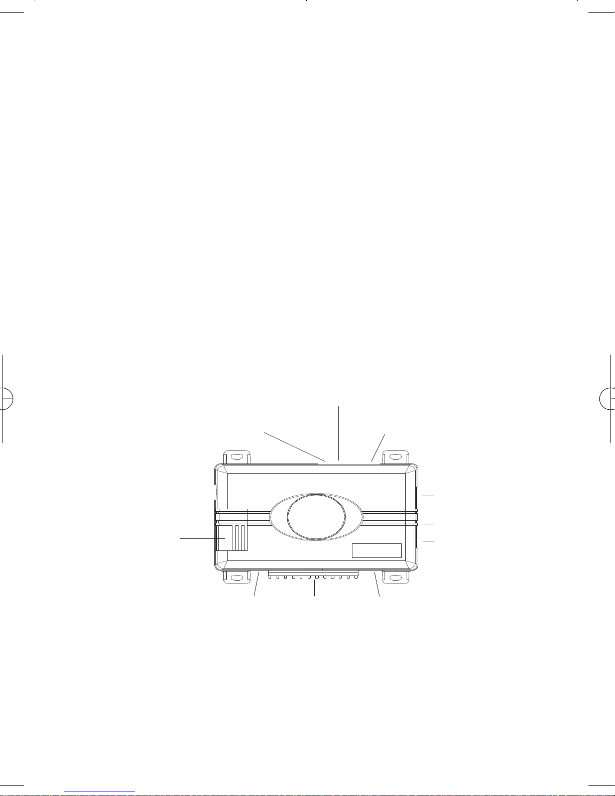
Control module
DEALER
MASTER
CONTROL LOOP
(NOT USED)
OPTIONAL
ANTENNA/RECEIVER
PORT (NOT USED)
PROGRAMMING
BITWRITER
PORT
®
FUSE/JUMPER/
10-AMP
LIGHT FLASH
ACCESS
VALET
SWITCH
12-PIN
MAIN
HARNESS
OPTIONAL
SENSOR
PORT
7-PIN DOOR MONITOR/
AUX PORT
DOOR LOCK PORT
LED

4
© 2009 Directed Electronics
Installation points to remember
This product represents many years of research and development. It is
very sophisticated and should be installed by experienced security
installers only. Please do not attempt installation of this product without
reading this guide. The system has been designed to provide the ultimate in security, coupled with limitless convenience and expansion
options.
Do not disconnect the battery if the vehicle has an anti-theft coded
radio. If equipped with an airbag, avoid disconnecting the battery if
possible.
IIMMPPOORRTTAANNTT!!
Please read this entire installation guide before
beginning the installation. The installation of this security system requires interfacing with many of the vehicle’s systems.
Many new vehicles use low-voltage or multiplexed systems
which can be damaged by low resistance testing devices,
such as test lights or logic probes. Test all circuits with a highquality digital multi-meter before making the connections.
I
MMPPOORRTTAANNTT!!
Many airbag systems will display a diagnostic code through their warning light after they lose power. Disconnecting the battery requires this code to be erased, a procedure that can require a trip to the dealer.s
Before you begin the installation
z
Check with the customer to determine the LED and Valet switch
location.
z
Remove the domelight fuse. This prevents accidentally draining the
battery.
z
Roll down a window to avoid being locked out of the car.

© 2009 Directed Electronics
5
After the install
z
Test all functions. The “Using Your System” section of the Owner’s
Guide is very helpful when testing.
z
When testing, don’t forget that this system is equipped with Nuisance Prevention Circuitry. NPC™can bypass both sensor zones, making them seem
to stop working.
z
Carefully reassemble the under-dash trim panels.
z
Inspect the engine compartment for tools that may have been left
behind.
Tools required
This is a general list of tools required to complete the installation of this
security system in most vehicles. Some vehicles may require additional
tools.
z
Digital multi-meter
z
Nutdriver and/or
socket set
z
Wire cutters/strippers
z
Panel removal tool
z
Solderless terminal crimpers
z
Drill bit set
z
Cordless power drill
z
Phillips head screw-
driver
z
Torx driver set
z
Work light
6
© 2009 Directed Electronics
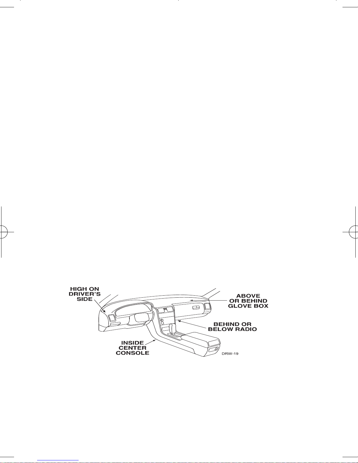
Deciding on component location
Control module
Never put the control module in the engine compartment!
The first step in hot-wiring a vehicle is removing the driver's side underdash panel to access the starter and ignition wires. If the control module
is placed just behind the driver's side dash it can easily be disconnected.
When locating the control module, try to find a secure location that will
not require you to extend the harnesses’ wires (they are 1.5 meters
long). Keep it away from the heater core (or any other heat sources) and
any obvious leaks.
Some good control module locations: Above the glove box, inside the
center console, above the underdash fuse box, behind or below above
the radio, etc.
© 2009 Directed Electronics
7
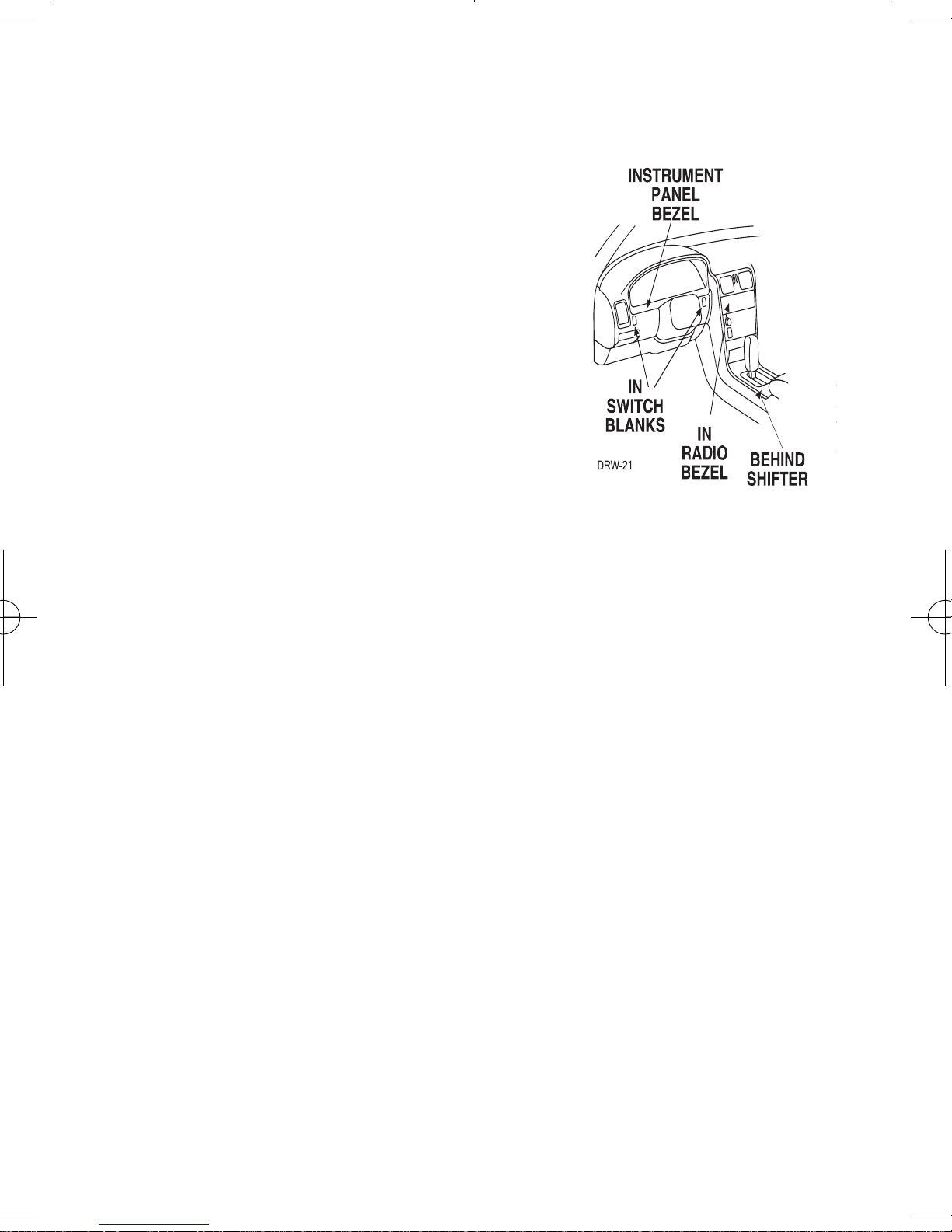
LED and Valet switch
Things to remember when positioning the LED and Valet switch:
• The LED should be visible from both
sides and the rear of the vehicle, if
possible.
• The LED and Valet switch should be at
least 1-1/2" clearance to the rear.
• It is easiest to use a small removable
panel, such as a switch blank or a
dash bezel. Remove it before drilling
your 5/16" hole.
IImmppoorrttaanntt!!
Do
NNoott
use a step drill bit (unibit) for drilling the
5/16” hole. It is recommended to use a 5/16” drill bit. Use
care to ensure the hole is drilled straight. Drilling at an angle
can cause product malfunction.
Starter kill relay
If the Starter Kill Relay or it’s connections are immediately visible upon
removal of the underdash panel, they can easily be bypassed.
Always make the relay and its connections difficult to notice from the
factory wiring. Exposed yellow butt connectors do not look like factory
parts, and will not fool anyone. For this reason, routing the starter kill
wires away from the steering column is recommended.
8
© 2009 Directed Electronics
Connecting your wires
Now that you have decided where each component will be located,
you’re going to find the wires in the car that the security system will be
connected to.
IImmppoorrttaanntt!!
Do not use a 12V test light or logic probe to find
these wires! All testing described in this manual is described
using a digital multimeter.
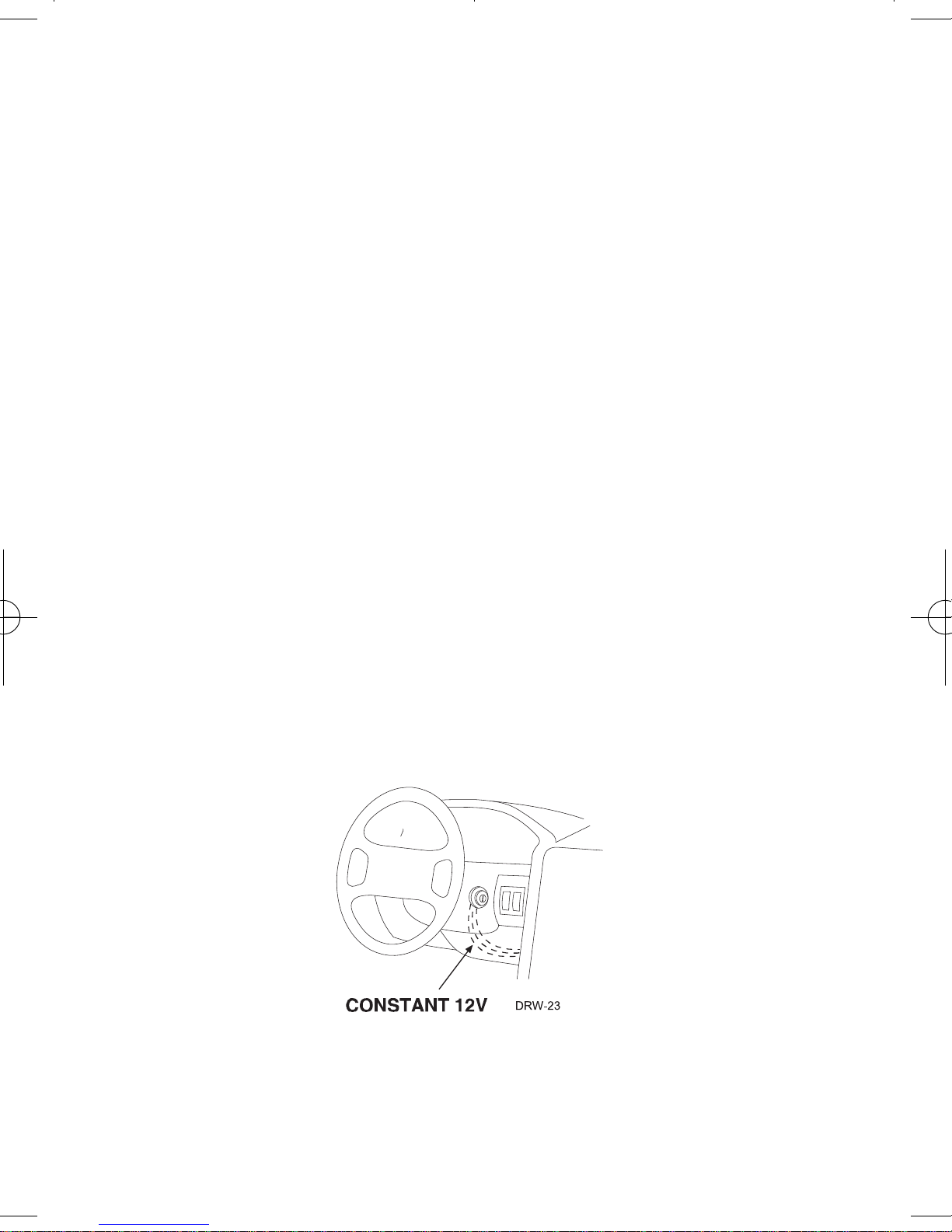
Obtaining constant 12V
We recommend two possible sources for 12V constant: The (+) terminal
of the battery, or the constant supply to the ignition switch. Always install
a fuse within 12 inches of this connection.
IImmppoorrttaanntt!!
Do not remove the fuse holder on the red (H1/11)
wire. It ensures that the control module has it’s own fuse, of the
proper value, regardless of how many accessories are added
to the main power feed.

© 2009 Directed Electronics
9
Finding the 12V switch ignition wire
The ignition wire is powered when the key is in the run or start position.
This is because the ignition wire powers the ignition system (spark plugs,
coil) as well as the fuel delivery system (fuel pump, fuel injection computer). Accessory wires, on the other hand, lose power when the key is in
the start position to make more current available to the starter motor. Use
the following procedure to find (+)12V with your multimeter.
1. Set to DCV or DC voltage (12V or 20V is fine).
2. Attach the (-) probe of the meter to chassis ground.
3. Probe the wire you suspect of being the ignition wire. The steering
column harness or ignition switch harness is an excellent place to
find this wire.
4. Turn the ignition key switch to the run position. If your meter reads
(+)12V, go to the next step. If it doesn’t, probe another wire.
5. Now turn the key to the start position. The meter display should
stay steady, not dropping by more than a few tenths of a volt. If it
drops close to or all the way to zero, go back to step 3. If it stays
steady at (+)12V, you have found an ignition wire.
10
© 2009 Directed Electronics
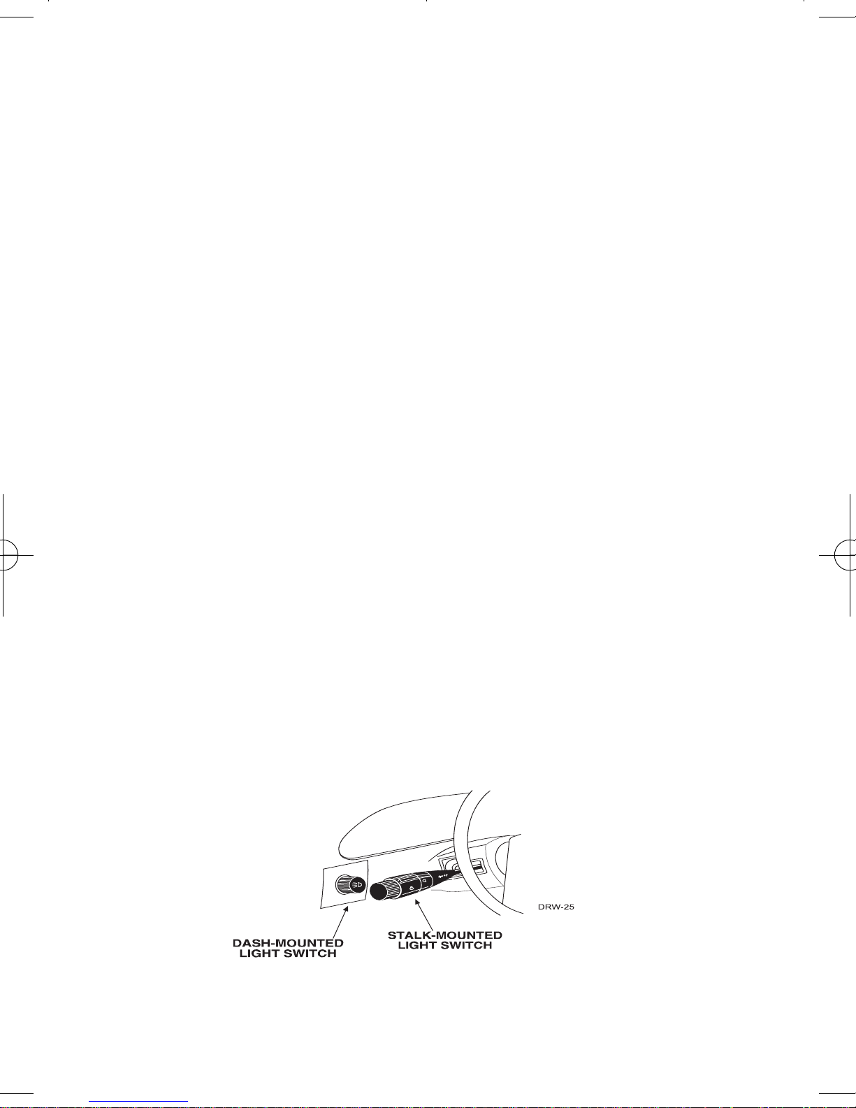
Finding a parking light wire
The parking light wire is often found near the switch. Many cars have the
switch built into the turn signal lever, and the parking light wire can be
found in the steering column. The same wire is often available in the kick
panel or running board.
To find the (+) and (-) parking light wire with your multimeter.
1. Set to DCV or DC voltage (12V or 20V is fine).
2. To find a (+) circuit, attach (-) probe of the meter to ground.
If you are looking for a (-) circuit, attach (+) probe of the meter to
(+) 12V.
3. Probe the wire you suspect of being the parking light wire. The
area near the headlight/parking light switch, or near the kick
panel, is an excellent area to start.
4. Turn on the parking lights. If your meter shows (+)12V, turn off the
parking lights and make sure it goes back to zero.
5. With the meter at zero, turn the parking lights On, and using the
dash light dimmer control, turn the brightness of the dash lights up
and down.
If the meter changes more than a volt when using the dimmer, look
for another wire. If it stays relatively close to (+)12V, you have
found your parking light wire.

© 2009 Directed Electronics
11
Finding the door pin switch circuit
The best places to find the door switch wire are:
At the pin switch: When testing at the pin switch, check the wire to
ensure that it “sees” all the doors. Often, the passenger switch will cover
all the doors even if the driver’s switch will not.
At the dome light: This may not be your best choice if the vehicle has
delayed domelight supervision, but it will work in vehicles with completely diode-isolated pin switches.
Often the door switch wires, described above, can also be found in the
windshield pillars, running boards or kick plates.
Use the following procedure to find the door pin switch wire with your
multimeter.
1. Set to DCV or DC voltage (12V or 20V is fine).
2. In most cars, fasten the (+) probe of your meter to (+)12V constant.
3. Using meter, probe the wire you suspect of being the door trigger
wire. If the meter reads (+)12V when any door is opened and the
meter goes to 0 with the door closed, you have found a (-) trigger
wire.
4. Fasten the (-) probe of your meter to ground and then using positive probe check for positive Door Trigger. If your meter displays
12V when the Door is opened and 0 when it is closed you have
found the (+) door trigger.
IImmppoorrttaanntt
: Make sure the wire you use “sees” all the doors some newer vehicles lack standard-type pinswitches. The
dome light in these vehicles is turned on when the door handle is lifted. There is usually a wire coming out of the door into
the kick panel to provide a (-) trigger for all doors.

12
© 2009 Directed Electronics
Main harness wire connection guide
Main harness wiring diagram
RED/WHITE (-)200mA Auxiliary Channel/Delayed Accessory Output
RED (+) 12V Constant Power Input
BROWN (+)Siren Output
YELLOW (+)Ignition Input
BLACK (-) Chassis Ground Input
VIOLET (+) Door Trigger Input
BLUE (-) Instant Trigger (Hood and Trunk Pin)
GREEN (-) Door Trigger Input
BLACK/WHITE (-) 200mA Domelight Supervison Output
WHITE/BLUE No Function
WHITE (+)Default/(-) Light Flash Output
ORANGE (-)500mA Ground When Armed
H1/1
H1/2
H1/3
H1/4
H1/5
H1/6
H1/7
H1/8
H1/9
H1/10
H1/11
H1/12
 Loading...