

Page 1
EVC350/EVC950
EVC300/EVC900
User Manual
Page 2

CONTENTS
INTRODUCTION ................................................................................................................... 1
Features ..............................................................................................................................................................1
Package Contents ..............................................................................................................................................2
INSTALLATION..................................................................................................................... 3
Getting Familiar with the EVC -Series................................................................................................................3
Main System ..................................................................................................................................................3
MIC .................................................................................................................................................................4
Camera...........................................................................................................................................................5
Remote Controller ..........................................................................................................................................6
Connections ........................................................................................................................................................8
Connecting Monitors (VGA Out/HDMI Out)...................................................................................................9
Connecting the Camera (Camera In) ............................................................................................................9
Connecting the MIC (MIC In) .......................................................................................................................10
Connecting the LAN (RJ-45)........................................................................................................................10
Connecting the Power (DC 12V) .................................................................................................................10
Connecting PC (VGA in/DVI In)...................................................................................................................11
Connecting the Audio (Audio In/Out)...........................................................................................................11
USB Storage (USB Ports)............................................................................................................................12
CAMERA AND MICROPHONE INTRODUCTION ................................................................... 13
Using the Camera .............................................................................................................................................13
Infrared Sensor (IR) ..........................................................................................................................................13
Positioning the MIC...........................................................................................................................................14
AVER EVC WIZARD SETUP ................................................................................................ 15
Start ..............................................................................................................................................................15
Language .....................................................................................................................................................16
Site Name ....................................................................................................................................................16
Network Setting............................................................................................................................................16
Public IP Configuration (Outside of Firewall): .............................................................................................17
Private IP Configuration (behind firewall port forwarding): .........................................................................18
SIP Setting ...................................................................................................................................................20
AVER EVC OPERATION ...................................................................................................... 23
Before You Begin..............................................................................................................................................23
Home Screen ....................................................................................................................................................23
Configuration Icons ......................................................................................................................................23
Camera and MIC Icons ................................................................................................................................24
WAN Address...............................................................................................................................................24
Real-Time Clock...........................................................................................................................................25
System Info ..................................................................................................................................................25
Dial ....................................................................................................................................................................26
Hang up the call ...........................................................................................................................................28
Page 3

Video Layout ................................................................................................................................................28
Phonebook ........................................................................................................................................................29
Group ...........................................................................................................................................................29
New Site (Contact in Phonebook) ...............................................................................................................36
Contacts List ................................................................................................................................................40
Favorite ........................................................................................................................................................40
Online Phonebook .......................................................................................................................................41
Call History........................................................................................................................................................41
General Setting .................................................................................................................................................44
Call Settings .................................................................................................................................................44
System Settings ...........................................................................................................................................47
Administrator ................................................................................................................................................49
Monitor .........................................................................................................................................................53
Date and Time..............................................................................................................................................54
Reset System ...............................................................................................................................................57
License .........................................................................................................................................................58
Skype for Business License.........................................................................................................................59
Default Layout ..............................................................................................................................................60
Video/Audio.......................................................................................................................................................62
Camera.........................................................................................................................................................62
Microphone ..................................................................................................................................................65
Video/Audio Codecs ....................................................................................................................................68
Network .............................................................................................................................................................69
LAN Configuration........................................................................................................................................69
IPv6 ..............................................................................................................................................................71
Advance Network .........................................................................................................................................73
Firewall .........................................................................................................................................................74
SIP................................................................................................................................................................75
SIP Configuration .........................................................................................................................................79
Gatekeeper ..................................................................................................................................................84
Test Utilities..................................................................................................................................................87
Skype for Business ......................................................................................................................................88
iSCSI ............................................................................................................................................................89
WEB CONFIGURATIONS..................................................................................................... 90
Using the WebTool ...........................................................................................................................................90
Phonebook ........................................................................................................................................................93
Edit and Save ...............................................................................................................................................93
Download Phonebook Entries .....................................................................................................................94
Upload Phonebook Entries ..........................................................................................................................94
Download Call History Entries .....................................................................................................................94
LDAP Setting................................................................................................................................................95
Online Phonebook .......................................................................................................................................95
Upload Files Setting (Group Call Only) .......................................................................................................96
Page 4

General Setting .................................................................................................................................................97
Enable Record .............................................................................................................................................97
Dual Stream Bandwidth Adjustment............................................................................................................97
Update System.............................................................................................................................................98
EZ Join .........................................................................................................................................................99
Customized Logo and Boot Animation ...........................................................................................................100
TROUBLESHOOTING ........................................................................................................ 101
Audio ...............................................................................................................................................................101
Video/Display ..................................................................................................................................................101
Network ...........................................................................................................................................................102
Others .............................................................................................................................................................104
SCENARIOS FOR LAN CONNECTION ............................................................................... 105
Public IP Configuration (Outside of Firewall) .................................................................................................105
Private IP Configuration (Behind Firewall with Port Forwarding) ..................................................................106
H.460 Gatekeeper with Firewall Traversal .....................................................................................................108
REMOTE CONTROL BATTERY SAFETY INFORMATION ................................................... 109
LIMITED WARRANTY........................................................................................................ 110
Limitations of Warranty ...................................................................................................................................110
Disclaimer of Warranty ...................................................................................................................................110
Limitation of Liability .......................................................................................................................................111
GOVERNING LAW AND YOUR RIGHTS ............................................................................. 111
FEDERAL COMMUNICATIONS COMMISSION STATEMENT (CLASS A) ............................. 111
Class A ITE .....................................................................................................................................................111
CE Class A (EMC) ..........................................................................................................................................111
COPYRIGHT ..................................................................................................................... 112
Trademarks .....................................................................................................................................................112
Disclaimer .......................................................................................................................................................112
Page 5

Introduction
Thank you for choosing EVC300/EVC350/EVC900/EVC950 which offers professional
videoconferencing experience in new cost performance benchmark.
EVC300/EVC350/EVC900/EVC950 give you the latest technologies; slim form factor, flexible
integration options and backward compatibility to most videoconferencing install bases. It makes any
business meetings and special events much more reliable, effective, and secure.
Features
EVC300/350: 4-sites embedded MCU support H.323 and SIP protocol video conferencing system
EVC900/950:10-sites embedded MCU support H.323 and SIP protocol video conferencing
system
Support full content sharing experience (send and receive) at 30fps, send content from VGA or
HDMI
Dual monitor support via HDMI1 and HDMI2/VGA
Support CIF (352x240) up to Full HD (1920x1080 30fps) video call
EVC300/EVC900 with PTZ camera is 16x Optics PTZ camera with 2Mp low lux sensor
EVC350/EVC950 with PTZ camera II is 18x Total zoom PTZ camera with 2Mp low lux sensor
Include one microphone array, much better audio pick up than competitor offering
10/100 and Gigabit Ethernet; video bandwidth from 64Kbps to 4Mbps
Support IPv4/IPv6 and Wake-on-LAN (WOL)
User-friendly on screen operation, support up to 22languages
Support Phonebook download, upload and edit
Call history lookups of received, placed and missed calls, allow directly saving it to favorite
contact list
Support H.460 Gatekeeper for NAT and firewall traversal
G.722.1C* wideband support
Infrared (IR) remote control has power button; system supports remote API for AV integration
Secure communication using AES 128bit encryption
*:G.722.1/G.722.1C, licensed from Polycom®
1
Page 6

1 2
/
3
4 5 6 7
8 9 10 11 12
13 14 15 16
Internet
Camera
Mic
PC / LaptopPC / Laptop
Audio InSpeakerDisplay 1Display 2 (HDMI)Display 2 (VGA)
1. Main System
2. Camera
3. Microphone
4. Remote Control
5. Power Adapter
6. Power Cord
7. VGA Cable
8. Mini Din 8 pin MIC Cable (5m)
9. HDMI Cable * 2
10. Camera Cable (3m)
11. RJ-45 Cable (3m)
12. DVI to HDMI Connecter
13. Warranty Card
14. Quick Installation Guide
15. AAA Batteries
16. Back Panel Label
Package Contents
The following items are included in the package. Please check if each item is available before using.
The power cord will vary depending on the standard power outlet of the country where it is sold.
The camera will vary depending on choosing EVC model of EVC300/EVC350/EVC900/EVC950.
2
Page 7
(2)(1) (3) (4)
Name
Function
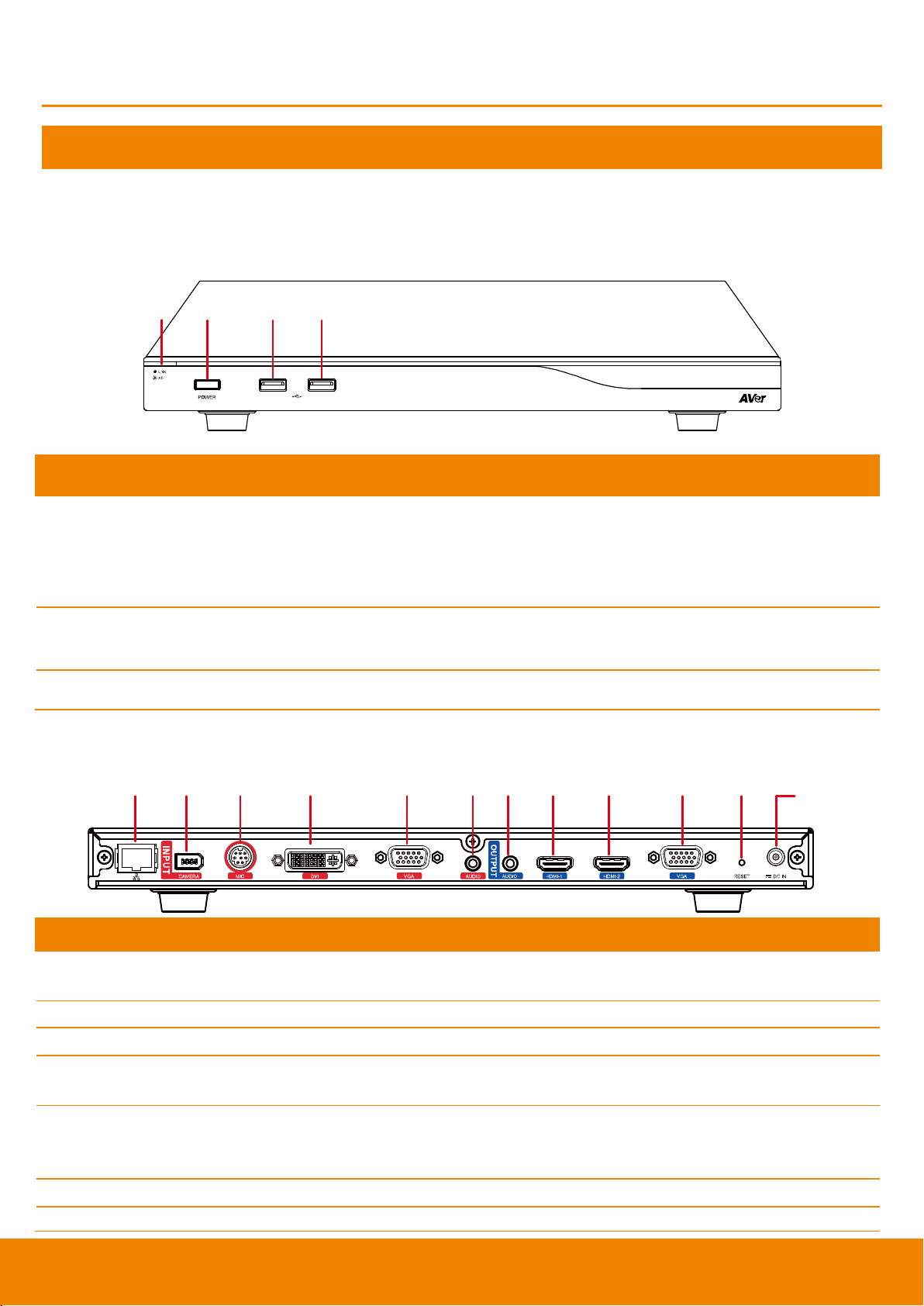
(1) LED Indicator
Show you the status of your LAN connection.
1. Solid Green: LAN connection is successfully
2. Flash Green: Data transmission is processing through the LAN
connection.
(2) POWER Button
Press this button to turn on/off main system. Red: power off; Blue: power
on
(3) & (4) USB Port
Use to connect the USB storage for system log saving and FW upgrade.
(1) (2) (3) (4) (5) (6)(7) (8) (9) (10) (11)
(12)
Name
Function
(1) LAN Port
Use the RJ-45 Ethernet cable to connect an IP-based network to the LAN
port.
(2) CAMERA IN Port
Connect the camera to the main system via a camera cable.
(3) MIC IN Port
Receive audio signal from MIC device via a mini din 8 pin MIC cable.
(4) DVI IN Port
Using the DVI to HDMI connector to transfer the DVI to HDMI interface and
through the HDMI cable connects to the PC or NB.
(5) VGA IN Port
Connect the VGA cable to the VGA input port located on the back panel, and
connect the other end of VGA cable to a VGA input source (ex. Document
camera, Laptop or Desktop) to input video signal.
(6) AUDIO IN Port
Receive audio signal from an external audio source through the audio cable.
(7) AUDIO OUT Port
Use to connect the main system to external speakers or amplifiers for audio
Installation
Getting Familiar with the EVC -Series
EVC includes Main System, MIC, Camera and Remote Controller.
Main System
Front Panel:
Back Panel:
3
Page 8

Name
Function
signal output.
(8) HDMI-1 Port
Connect an HDMI cable from the HDMI monitor to HDMI-1 output port
located on the back panel. The HDMI interface allows you to transmit both
audio and video signals over a single cable (HDMI cable). In dual screen
configuration, the output screen connected to this port will be set up to
primary screen automatically.
(9) HDMI-2 Port
Connect the HDMI cable to the HDMI-2 output port located on the back
panel, and connect the other end of HDMI cable to a display device to output
both video and audio signal. In dual screen configuration, the output screen
connected to this port will be set up to secondary screen automatically.
(10) VGA OUT Port
Connect the VGA cable to the VGA output port located on the back panel,
and connect the other end of VGA cable to a display device to output video
signal. In dual screen configuration, the output screen connected to this port
will be set up to secondary screen automatically.
(11) RESET Button
Press it to reboot the main system unit.
(12) POWER Port
Connect the power supply cord and adapter to the power port located on the
back panel. And connect the other end of the power cord to a suitable power
outlet.
Name
Function
(1) Mute
Mute/Unmute the Mic. Blue: Unmute; Red: Mute
(2) MIC OUT Port
Outputs audio signal from the MIC to main system.
(3) MIC IN Port
Receive audio signal from the second MIC and pass it through the MIC
OUT to the main system.
MIC
4
Page 9

Name
Function
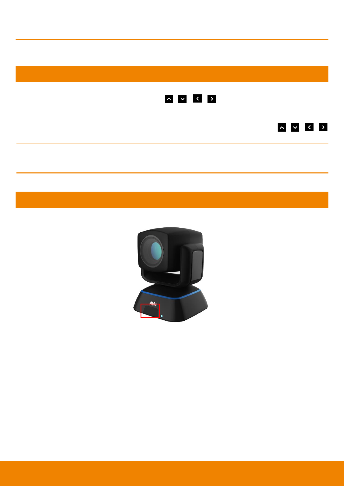
(1) IR Sensor
Receive IR signal from the remote control for system operation. Amber
light blinks when it detects key pressing event from remote.
(2) CAMERA OUT Port
Connect the camera cable to the CAMERA OUT port located on the back
of camera and CAMERA IN port located on the back panel of main
system for a video transmission.
Camera
5
Page 10

Zoom
Layout
Vol
Presentat ion
(1)
(3)
(4)
(7)
(5)
(10)
(12)
(14)
(16)
(20)
(22)
(23)
(2)
(6)
(9)
(8)
(11)
(15)
(18)
(17)
(21)
(25)
(24)
(13)
(19)
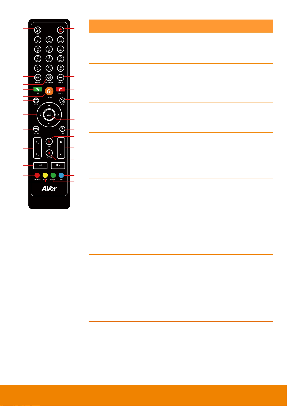
Name
Function
(1) Info
Press this button to display the call statistics
information.
(2) Power
Press this button to power on/off the main
system.
(3) Numeric Pad
a. Use to enter alphanumeric. Press
button and hold can switch between
numeric mode and alphanumeric mode.
b. Press number button 0~ 9 to switch the
number frame in main(enlarge) view while
conferencing call ( When Voice Activated
Layout Switch is disabled).
(4) Keypad
In enter mode, press this button to display the
on-screen keyboard.
(5) Phonebook
Search contacts to make a call.
Add, edit, delete or create group contact
entries.
(6) Delete
Press this button to back delete one character
at a time.
(7) Call
Start a call.
(8) Home
Bring up the main screen.
(9) Hang up
End the call.
(10) Help
In Home menu and video screen mode, press
it to display on-screen help information.
(11) Back
Return to previous OSD menu.
(12) Navigation
Buttons
( , , , )
c. Use these buttons to navigate through
the selections in OSD menus or
on-screen keyboard.
d. Pan and tilt the camera to adjust the
viewing.
e. Pan, tilt the zoomed in camera image or
captured image.
(13) Enter
a. Make a selection in OSD menus.
b. Accept incoming calls.
c. Display the site name and icon during
the meeting.
d. Auto Focus function(PTZ camera only)
(14) Far/Near
Select to control either near site or far site
camera. The cam ctrl icon will appear on the
screen to indicate which site’s camera you
are controlling. The cam ctrl icon will
disappear after press the Far/Near key 5 sec.
Remote Controller
The remote controller requires two “AAA” batteries (included). Make sure the batteries are installed
properly before using the remote controller. Aim the remote controller at the infrared sensor of your
AVer EVC camera to remote control the unit.
6
Page 11
Zoom
Layout
Vol
Presentat ion
(1)
(3)
(4)
(7)
(5)
(10)
(12)
(14)
(16)
(20)
(22)
(23)
(2)
(6)
(9)
(8)
(11)
(15)
(18)
(17)
(21)
(25)
(24)
(13)
(19)
Name
Function
(15) Input
Switch screen display between camera
screen and input source screen.
(16) Zoom +/-
Increase/decrease the camera zoom or the
captured image magnifications.
(17) Vol +/-
Increase/decrease the speaker volume.
(18) Mute
Mute/Unmute the MIC. The mute icon will
appear when the MIC is muted. The mute
icon will become translucent after enabling 5
sec.
(19) Record
Start/Stop video recording. The video
recording can only be saved to a USB flash
drive. You do not need to be on a video
conference to record.
(20) Presentation
Share the content that comes from either the
VGA input source or the DVI input source.
The present icon will appear on the screen
when the presentation function is enabled.
The icon will disappear after 5 sec.
(21) Layout
Change the screen layout.
(22) AVer Point
While using EZDraw, press AVer point button
can share EZDraw screen view on EVC
presentation view.
(23) Preset
Press and hold for 3 sec. to set the position of
the camera to a preset from 0~99.
Press to move the camera to a selected
preset point number.
(24) Snapshot
Capture the image from the camera(OSD
menu is not included) and save to external
USB pen drive.
(25) Dual
Switch to dual screen mode. This splits
the video conferencing screen and
present screen onto two separate
monitors (two monitors must be
connected to use the feature, one
through HDMI and one through
VGA/HDMI-2).
Press and hold can switch to OSD menu
between primary and secondary screen.
7
Page 12
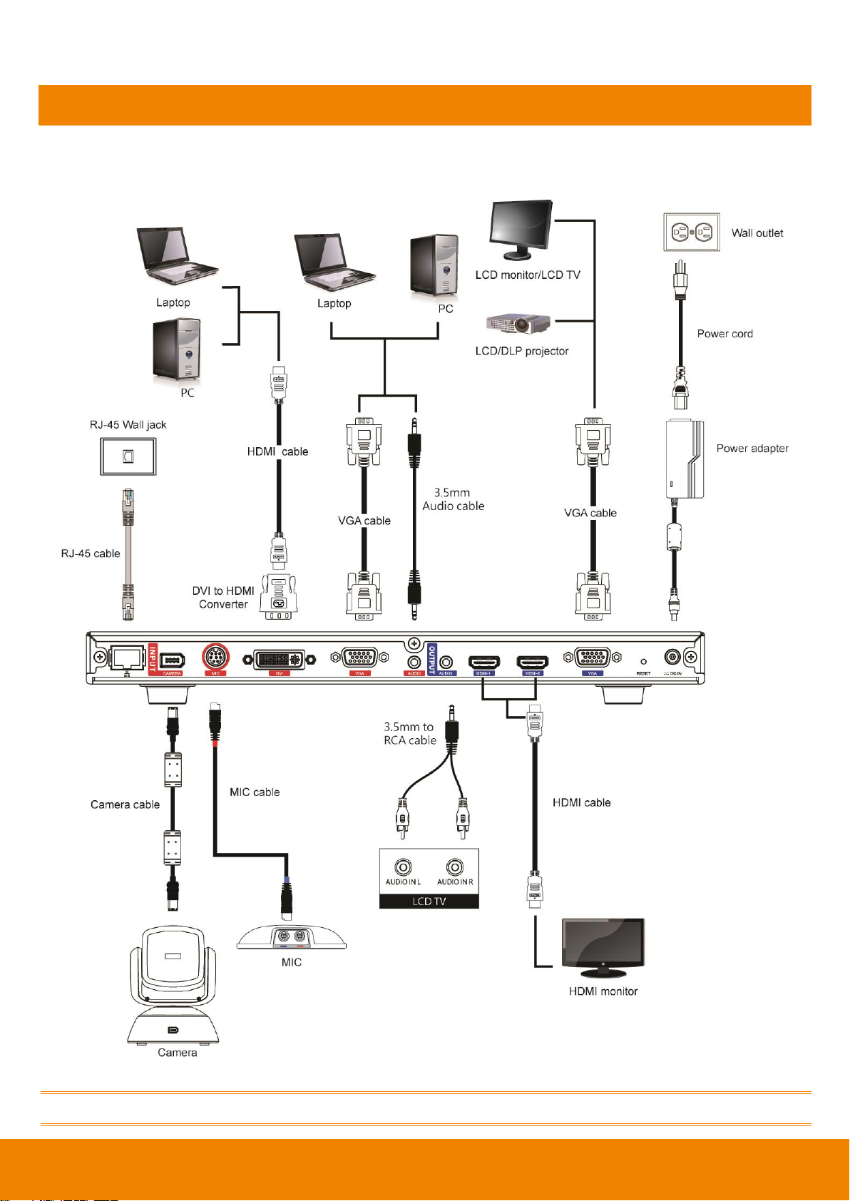
Connections
Before making the connections, make sure all devices are powered off. Refer to the illustrated
connections below and also to the user manual of the device you are connecting to the EVC300 /
EVC350 / EVC900 / EVC950 system.
Make sure all connections have been connected successfully before powering on the system.
8
Page 13
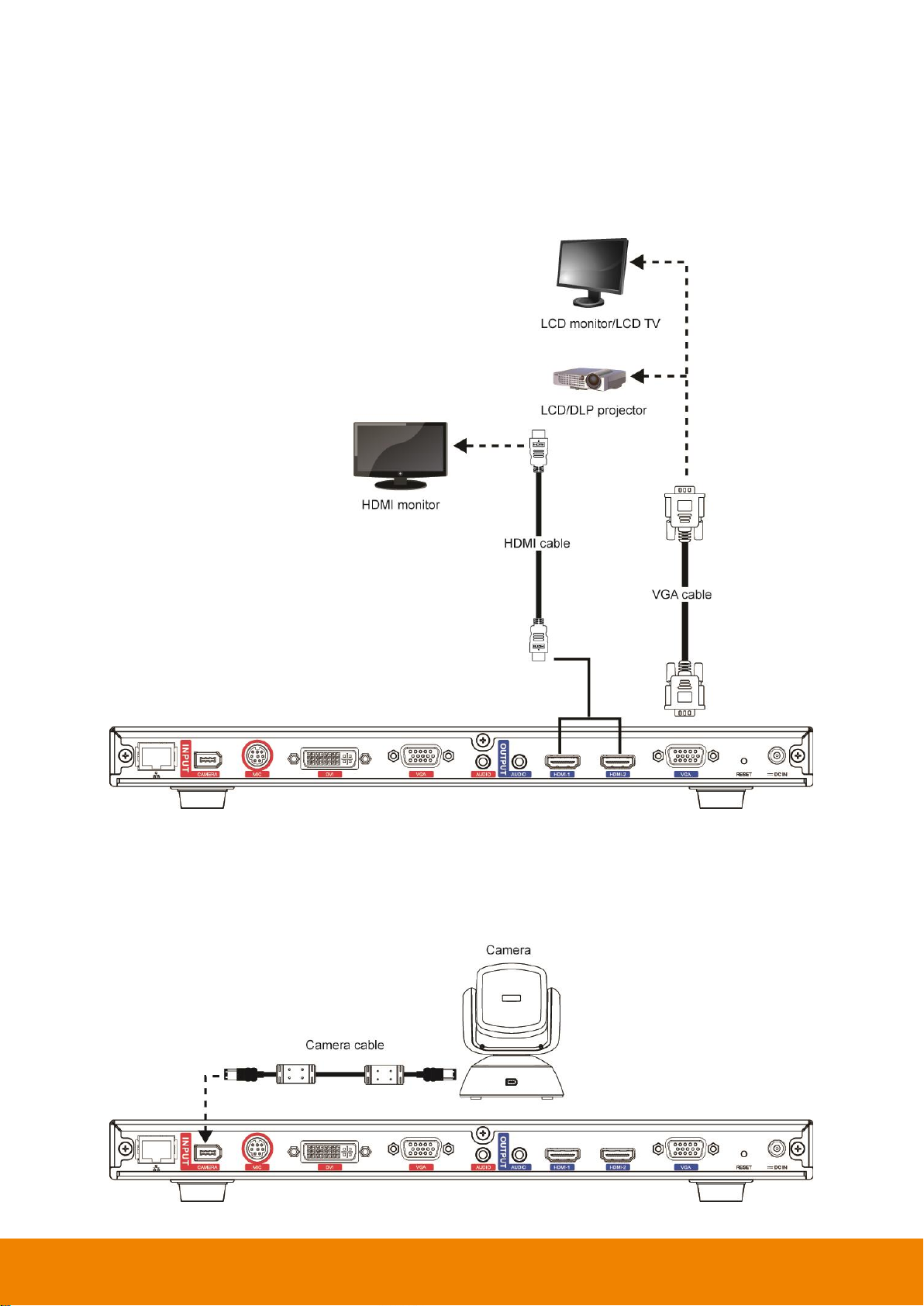
Connecting Monitors (VGA Out/HDMI Out)
Locate the VGA/HDMI input port of the graphics display device and connect it to VGA OUT/HDMI
OUT port of the AVer EVC with the supplied VGA/HDMI cable. You can connect the VGA OUT and
HDMI-1 OUT ports or HDMI-1 OUT and HDMI-2 ports at the same time upon a dual screen
configuration. The HDMI-2 output and VGA output port displays screen scene and resolution are
same.
Connecting the Camera (Camera In)
Locate the port on the back of the camera and connect it to the CAMERA IN port of the EVC with the
supplied camera cable.
9
Page 14
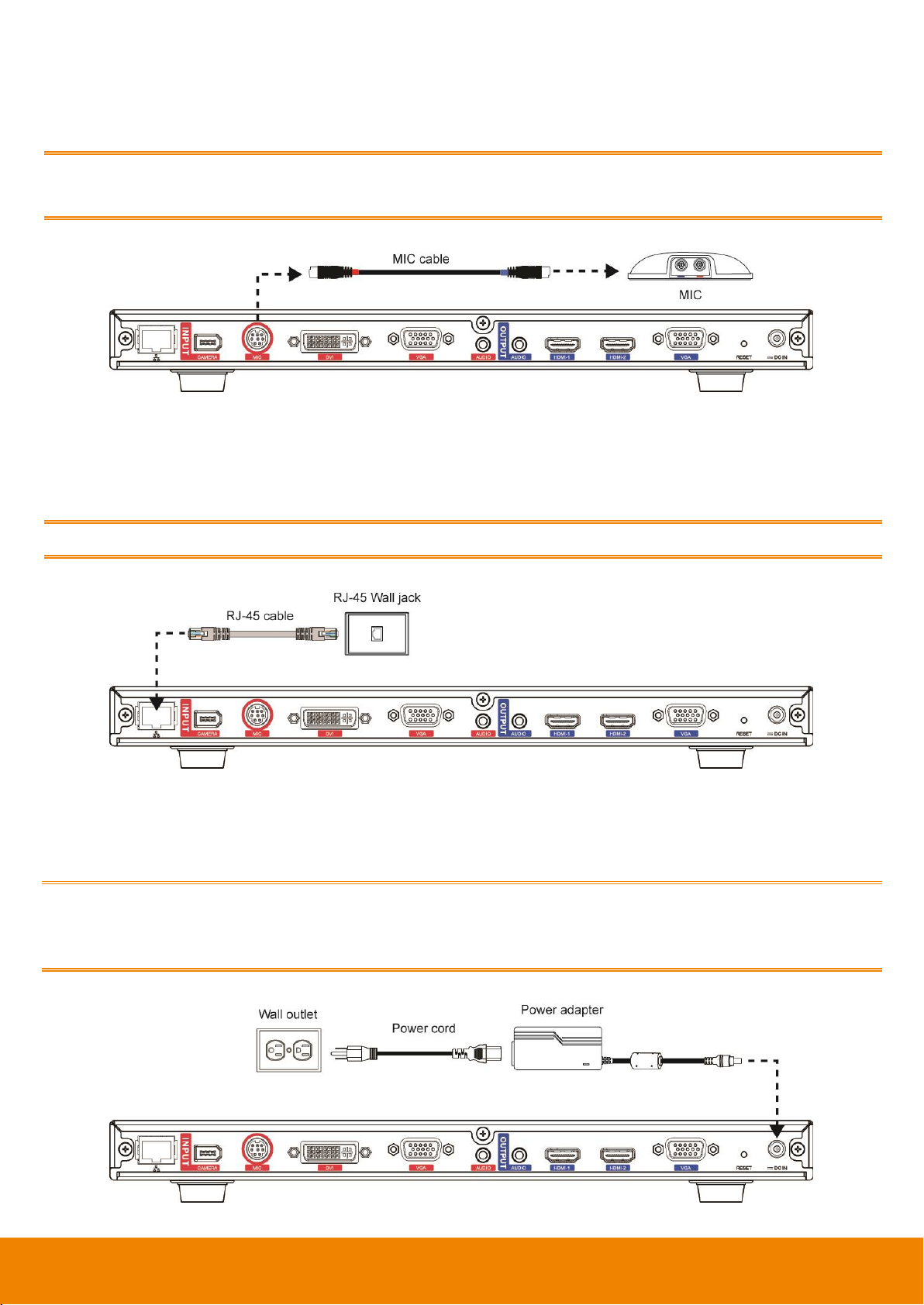
Connecting the MIC (MIC In)
Use the supplied MIC cable and connect the red tag connector to the MIC IN port of the EVC. Then
connect the other end of the MIC cable with the blue tag to MIC OUT port.
Press the button on the top of AVer EVC-MIC to mute/un-mute the MIC.
Please connect the cable to the port follow by the color on the cable and port, ex. red to red.
Connecting the LAN (RJ-45)
Connect the LAN port of AVer EVC to a RJ-45 wall jack or Ethernet hub with the supplied RJ-45
cable.
It is requires an IP-based network before beginning LAN connection.
Connecting the Power (DC 12V)
Connect the power adapter to a standard 100V~240V AC power outlet with the supplied power
adapter and power cord.
(1) To prevent shock, make sure all the connections on the main system are connected
successfully before connecting the power cable and turning on the power.
(2) Make sure to use the supplied available power adapter.
10
Page 15
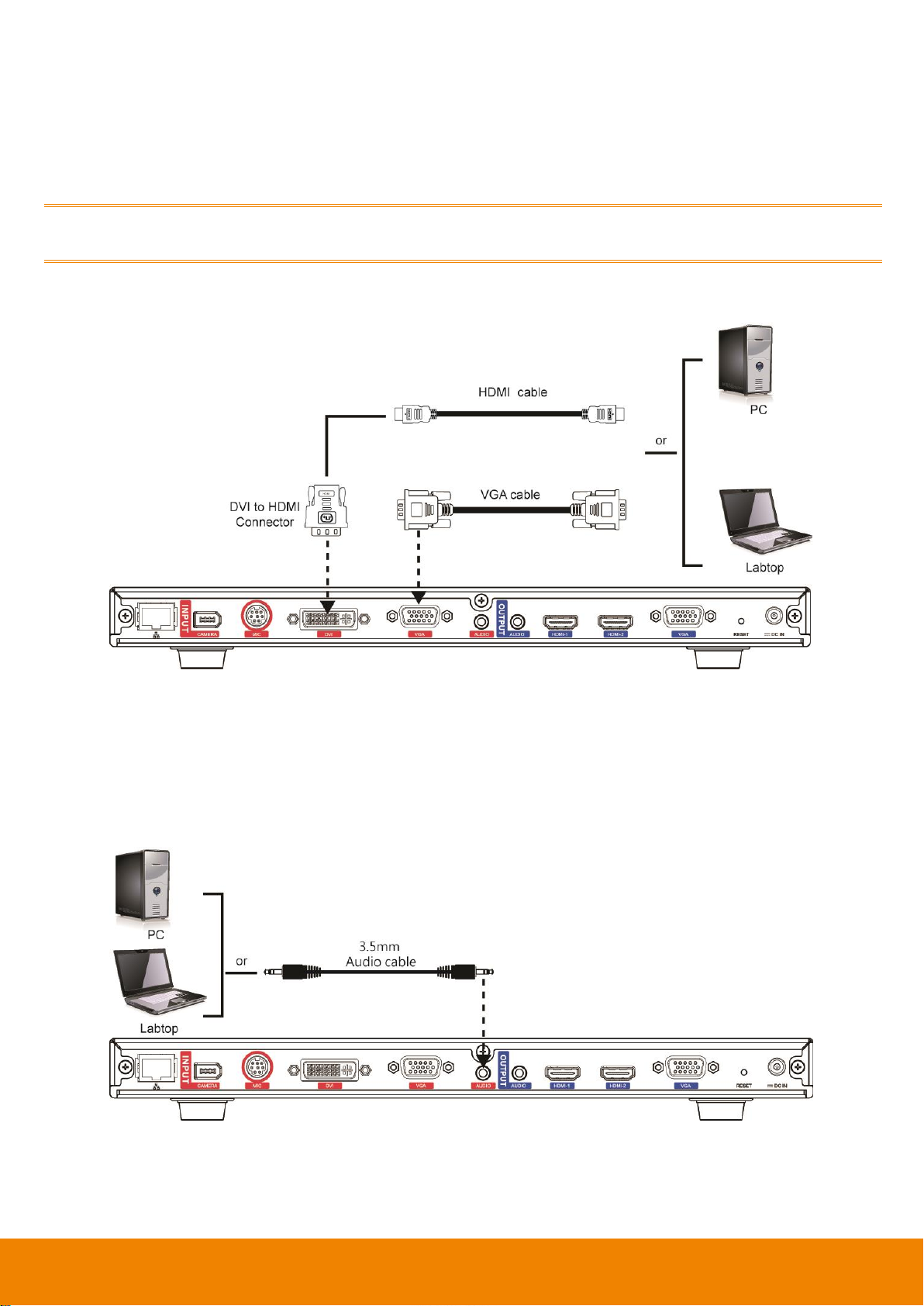
Connecting PC (VGA in/DVI In)
Locate the VGA output port of the Laptop or Desktop and connect it to VGA IN port of EVC with the
supplied VGA cable for an image display.
Use the supplied DVI to HDMI connector and connect to the HDMI port of Laptop or Desktop with
HDMI cable.
To share the video signal from the computer, press PRESENTATION and select “VGA” or ”DVI”
source.
Connecting the Audio (Audio In/Out)
AUDIO IN:
Locate the AUDIO output port of the Laptop or Desktop and connect it to AUDIO IN port of AVer EVC
with the supplied 3.5mm Audio cable.
11
Page 16
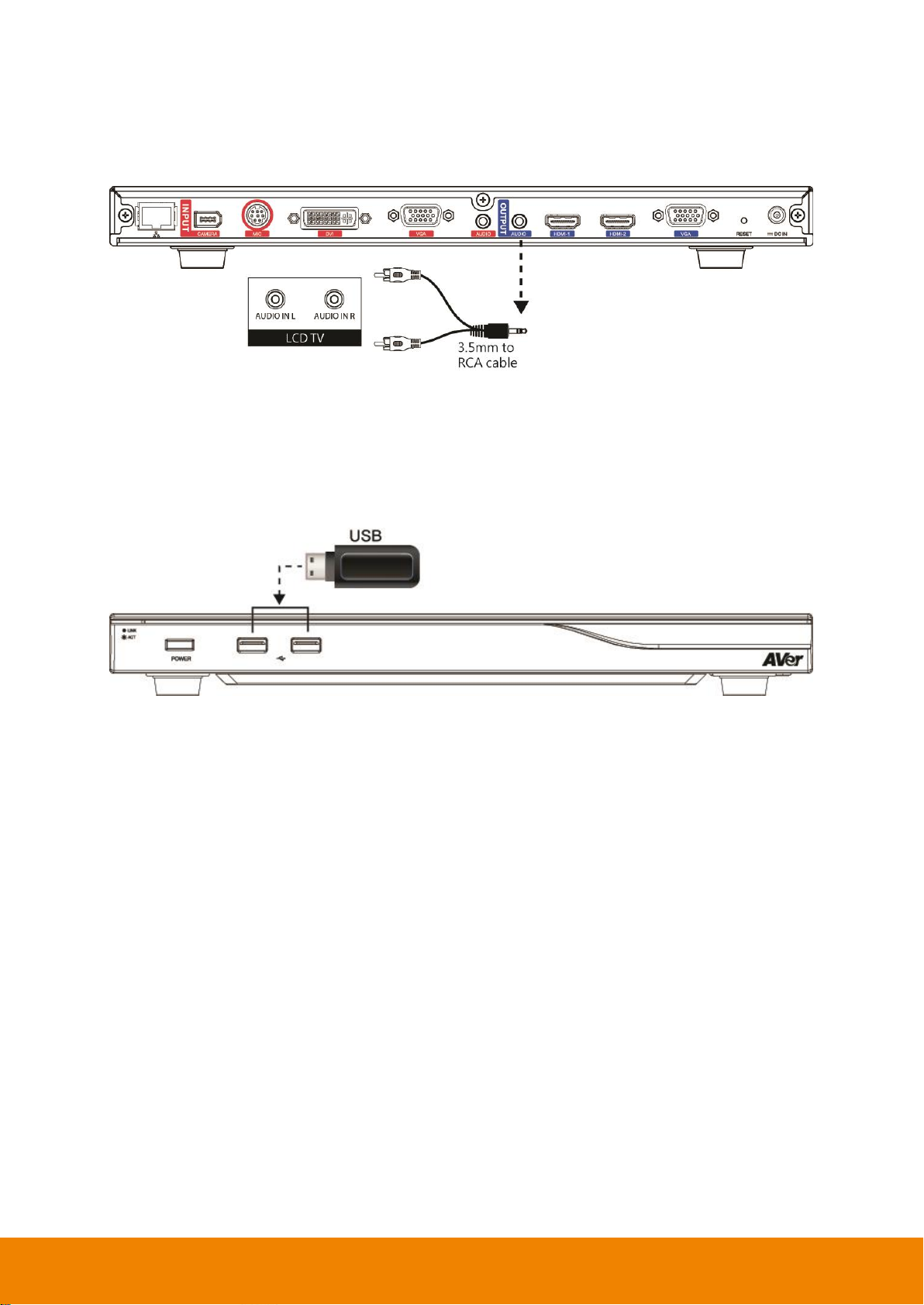
AUDIO OUT:
Locate the AUDIO in port of the LCD TV speaker or normal speaker and connect them to AUDIO OUT
port of EVC with a RCA cable.
USB Storage (USB Ports)
EVC main system supports two USB2.0 interface for saving data.
[Note] The USB ports only support USB pen drive for F/W upgrading and saving log file; they DO
NOT supply 5V power for any external devices.
12
Page 17
Camera and Microphone Introduction
This chapter explains the best way to position EVC300 / EVC350 / EVC900 / EVC950 in a conference
room.
Using the Camera
EVC300 / EVC900 includes a detached camera that can pan (+-100 deg. range), tilt (+-25 deg.
range) and zoom (16x Optics) by using the , , , and zoom +/- buttons on remote
controller.
EVC350 / EVC950 includes a detached camera that can pan (+-130 deg. range), tilt (+90/-25 deg.
range) and zoom (18x total zoom with 12x Optical, 1.5x Digital zoom) by using the , , ,
and zoom +/- buttons on remote controller.
Avoid physically turn camera while system is powered on to prevent permanent damaging the
motors and gears and void the warranty. Always use the remote control to pan and tilt the camera
head.
Infrared Sensor (IR)
Aim the remote controller at the camera infrared sensor to operate the unit.
13
Page 18
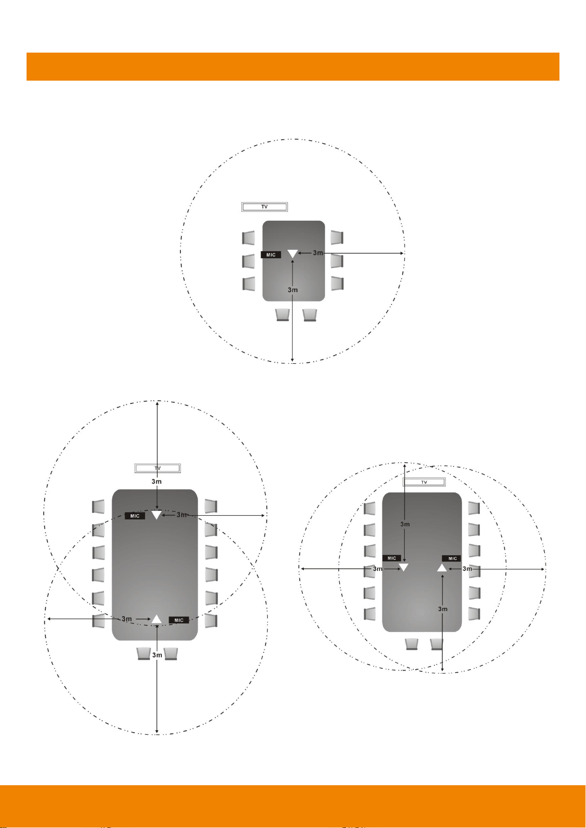
Positioning the MIC
The best distance for EVC-MIC to receive audio signal is within 3m. The EVC-MIC can connect up to
4 in one chain.
Single Microphone
Two Microphones
14
Page 19
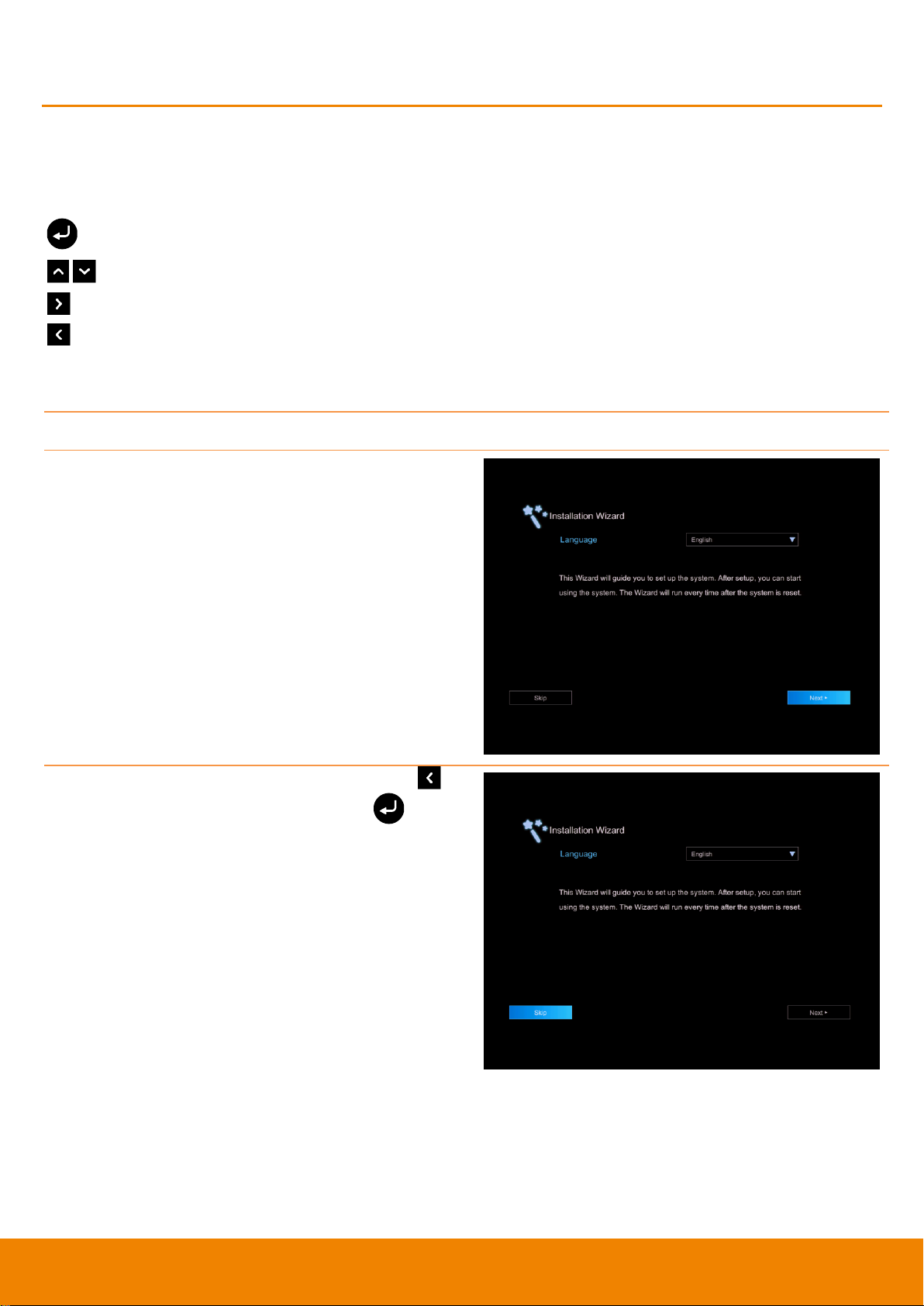
Start
Please follow the below description to complete the wizard setup.
Connect your EVC system well and turn on the
power. After your EVC system starting, user will
see the Installation Wizard screen shown up.
If you want to pass the Wizard setup, press
button move to Skip button and press to go
to Home page.
AVer EVC Wizard Setup
For the first time using AVer EVC system, the Installation Wizard will guide the user to setup EVC
system step by step. After completing the wizard setup, user may start to use the EVC system.
In Installation Wizard, user can use the following buttons on remote controller to move between the
selections and make/confirm selection.
: To expand the drop-down list, make/confirm the selection.
/ : Move the cursor up or down.
: Move the cursor to right or on Next button.
: Move the cursor to left or on Back button.
15
Page 20
Language
Select the language of the EVC system.
Press to expand the drop-down list. Then,
use or button to move the selection and
press to make the selection. After selecting,
press to move to Next option and press
to go next step.
Site Name
Assign a name for EVC system. Use the numeric pad on remote controller to enter the site
name.
After entering the site name, press to move to
Next button and press to go next step.
To go back to last step, press to move to Back
option and press to confirm.
[Note]
(1) Repeat press the number button to select the
character that user wants to enter.
(2) The site name is character only
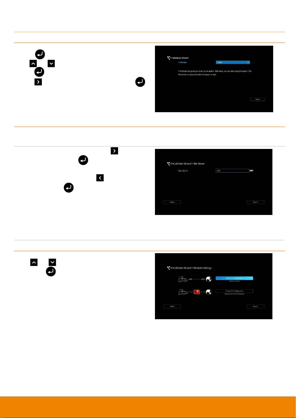
Network Setting
Select the network environment that user has used.
Use or button to move to the selection
and press to confirm the selection.
[Note] User can refer to chapter of Scenarios For
LAN Connection for the description of network
environment.
After selecting the network setting option, user
need to configure the network parameters. Follow
the below description to setup the network
settings.
16
Page 21
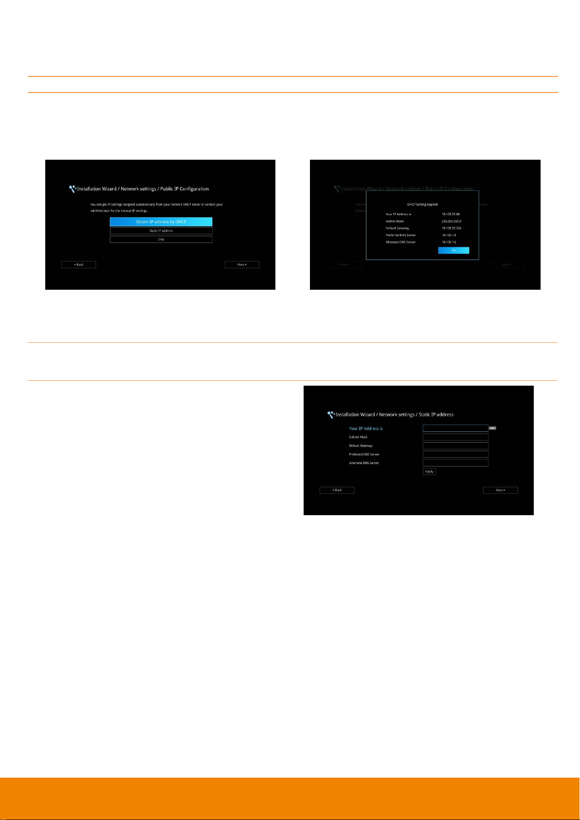
Public IP Configuration (Outside of Firewall):
Your EVC system is connecting directly to the internet. Select the IP mode.
Obtain IP address by DHCP: Configure the system to automatically obtain an IP address from the
DHCP server. The EVC system will automatically get an IP address which assigned by your DHCP
server on LAN. The IP address and related information will display. Click OK to accept the setting.
Static IP: Configure the system to use the assigned IP address. Select this when the public IP
address is available.
Enter the following information and click Apply to save the settings. To go to next step, click Next
and click Back to go back to Network Setting page.
1. Your IP Address is: Enter your IP address
manually.
2. Subnet Mask: Enter the subnet mask address
when the system does not automatically obtain
the subnet mask
3. Default Gateway: A gateway is a network
point that acts as an entrance to another
network. Enter the gateway address when the
system does not automatically obtain the
gateway.
4. Preferred DNS Server: Domain Name
System (DNS) servers convert human friendly
names (for example: www.example.com) to IP
addresses (218.77.272.166) that let machines
be found on the network. The preferred DNS
server is the one your computer asks first. The
alternate is a backup. Enter the Preferred and
Alternated DNS Server address.
5. Alternate DNS Server: Enter another Domain
Name server for second choice.
17
Page 22
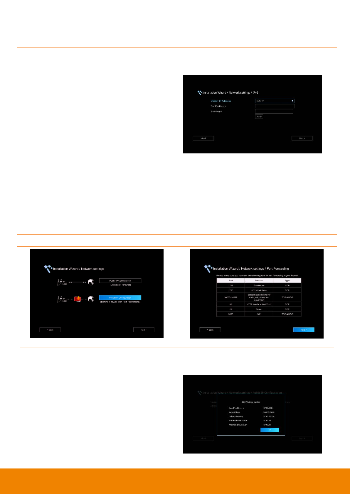
IPv6: IPv6 is an evolutionary upgrade to the Internet Protocol. IPv6 will coexist with the older IPv4 for
some time. IPv6 addresses are 128-bit IP address written in hexadecimal and separated by colons.
Select and enter the following information and click Apply to save the settings. To go to next step,
click Next option and click Back to go back to Network Setting step.
1. Obtain Address is
(1) Static IP: Configure the system to use
the assigned IP address. Select this
when the public IP address is available.
(2) Auto: Obtain the dynamic IP address
automatically. User needs to enter the IP
address and prefix length in following.
2. Your IP Address is: Enter your IP address
manually.
3. Prefix Length: Prefix Length allows you to
place as many IPv6 devices as the underlying
network medium allows.
Private IP Configuration (behind firewall port forwarding):
Your EVC system is connecting to the internet through a firewall.
Please make sure you have set the following ports in port forwarding in your firewall. Then, click
Next to select the IP mode of your network
Obtain IP address by DHCP: Configure the
system to automatically obtain an IP address from
the DHCP server. The EVC system will
automatically get a IP address which assigned by
your DHCP server on LAN. The IP address and
related information will display. Click OK to accept
the setting.
18
Page 23
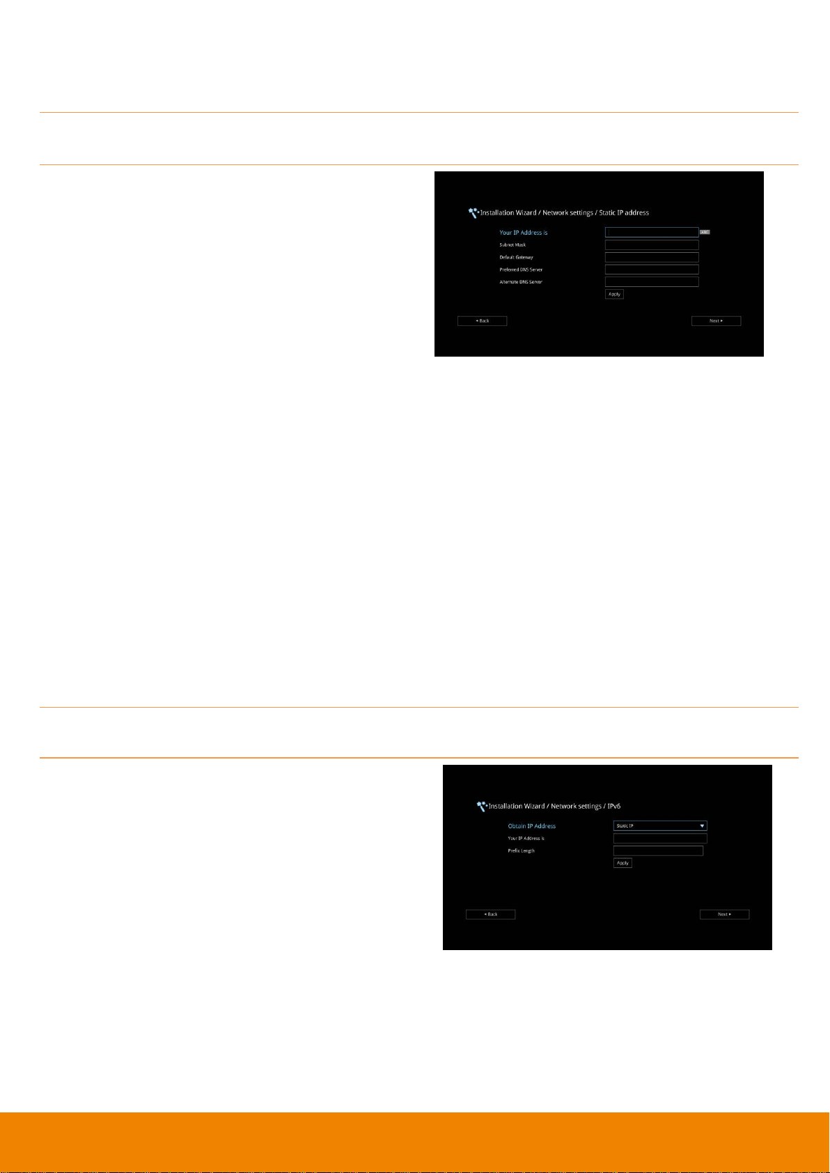
Static IP: Configure the system to use the assigned IP address. Select this when the public IP
address is available.
Enter the following information and click Apply to save the settings. To go to next step, click Next
and click Back to go back to Network Setting page.
1. Your IP Address is: Enter your IP address
manually.
2. Subnet Mask: Enter the subnet mask address
when the system does not automatically obtain
the subnet mask
3. Default Gateway: A gateway is a network
point that acts as an entrance to another
network. Enter the gateway address when the
system does not automatically obtain the
gateway.
4. Preferred DNS Server: Domain Name
System (DNS) servers convert human friendly
names (for example: www.example.com) to IP
addresses (218.77.272.166) that let machines
be found on the network. The preferred DNS
server is the one your computer asks first. The
alternate is a backup. Enter the Preferred and
Alternated DNS Server address.
5. Alternate DNS Server: Enter another Domain
Name server for second choice.
IPv6: IPv6 is an evolutionary upgrade to the Internet Protocol. IPv6 will coexist with the older IPv4 for
some time. IPv6 addresses are 128-bit IP address written in hexadecimal and separated by colons.
Select and enter the following information and click Apply to save the settings. To go to next step,
click Next option and click Back to go back to Network Setting step.
1. Obtain Address is
(1) Static IP: Configure the system to use
the assigned IP address. Select this
when the public IP address is available.
(2) Auto: Obtain the dynamic IP address
automatically. User needs to enter the IP
address and prefix length in following.
2. Your IP Address is: Enter your IP address
manually.
3. Prefix Length: Prefix Length allows you to
place as many IPv6 devices as the underlying
network medium allows.
19
Page 24
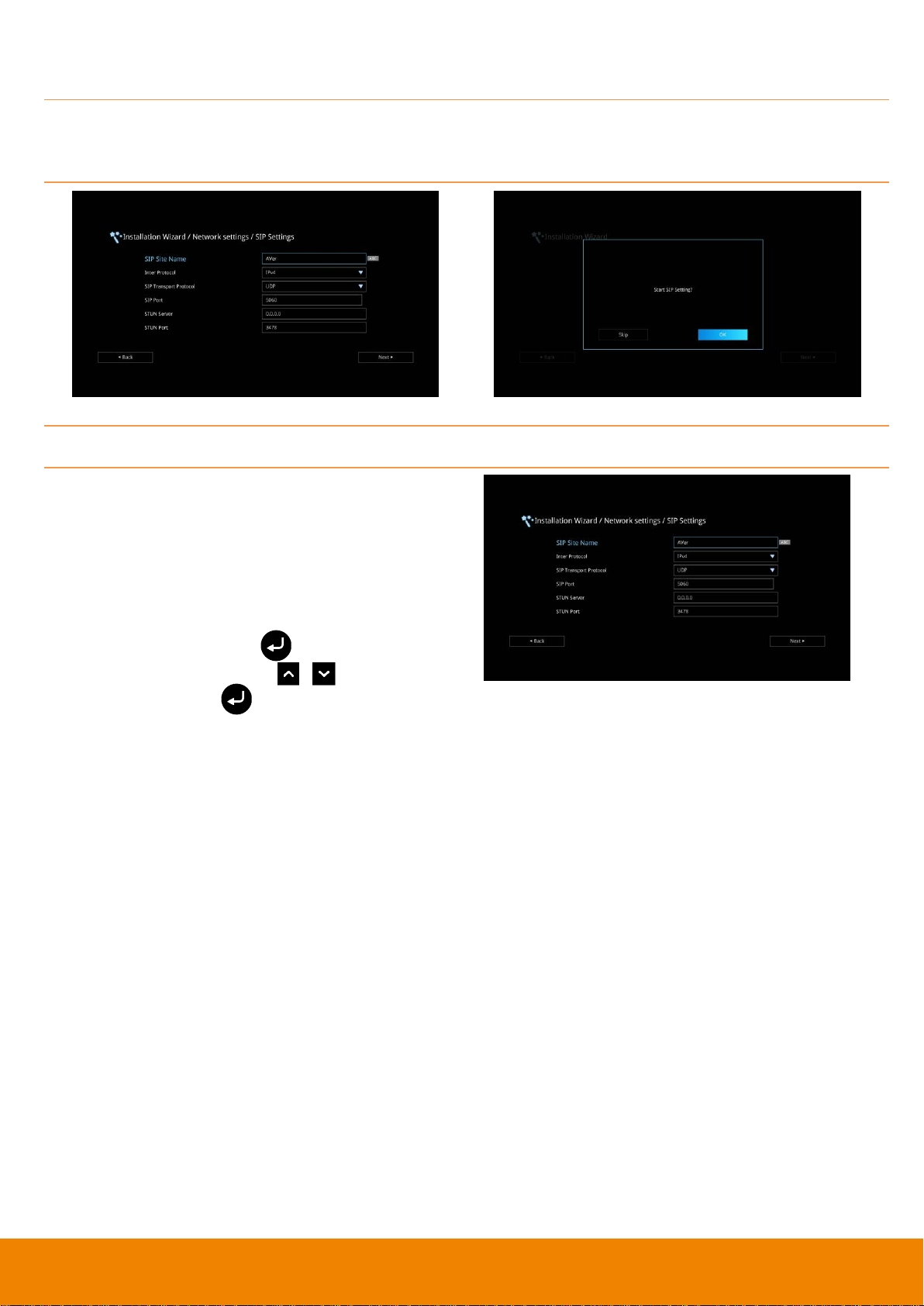
SIP Setting
Session Initiation Protocol (SIP) allows you around the world to communicate using your supported
devices over the Internet. After setting network, user can choose to setup SIP or Skip SIP setting.
To setup SIP, enter or select the following information
1. SIP Site Name: Enter the SIP site name for
others to identify. The SIP site name may be
the same or different then the domain for Web
activity. Use numeric pad to enter the SIP site
name in column.
2. Internet Protocol: Select to use IPv4 or IPv6
as IP protocol. Press to expand
drop-down list and use , to move the
selection. Press to confirm the selection.
3. SIP Transport Protocol: Select the SIP
Transport Protocol type from the drop-down list
for using. There are two types of Internet
Protocol (IP) traffic. They are Transmission
Control Protocol (TCP) and User Datagram
Protocol (UDP). To ensure proper connection,
verify if both calling parties are using the same
transport protocol. By default, it is set to UDP.
(1) TCP: TCP is connection oriented. Once a
connection is established, data can be sent
bidirectional.
(2) UDP: UDP is a simpler, connectionless
Internet protocol. Multiple messages are
sent as packets in chunks using UDP.
4. SIP Port: Change this value only if you use
specific settings in your network system. By
default, the SIP port is set to 5060.
5. STUN Server: STUN (Session Traversal
Utilities for NAT) is a standardized set of
methods and a network protocol to allow an
end host to discover its public IP address if it
is located behind NAT.
6. STUN Port: Enter the port number of STUN
server.
20
Page 25
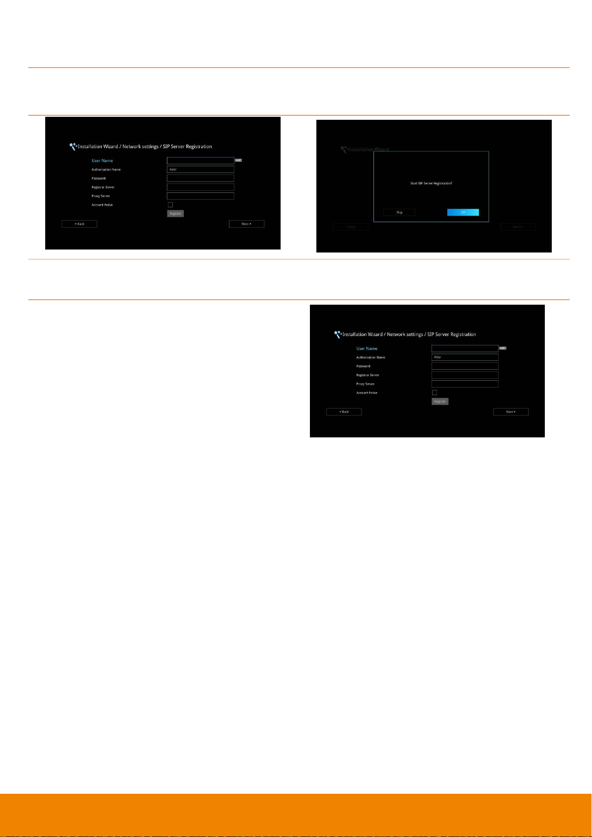
SIP Server Registration
A typical SIP session involves a client requesting a session with a SIP server. After the request is
received, the SIP server returns a response to the user indicating the availability of the session.
After setting SIP, user can choose to setup SIP Server Registration or Skip.
To setup SIP Server Registration, enter the following information and click Register to save the
settings. After completing, click Next to go next step.
1. Terminal Name: Enter the terminal server
name.
2. Terminal Password: Enter the password of
terminal server.
3. Registrar Server: Registrar Server accepts
registrations from users and places these
registrations, (which is essentially location
information), in a database known as a
location service. Enter the Registrar Server
name that you want to use.
4. Proxy Server: Proxy Server is computing
device (typically a server) that interfaces
between data processing devices and others
within a communications network. These
devices may be located on the same local area
network or an external network. Enter the used
Proxy Server name.
21
Page 26
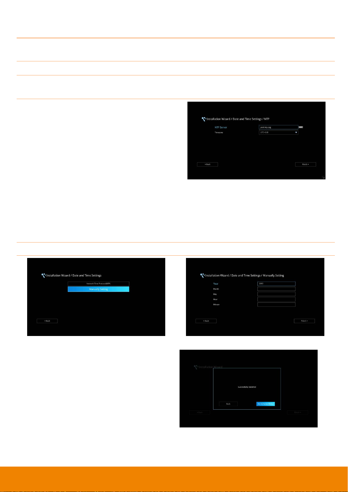
Date and Time Setting
Setup the EVC system date and time. User can choose to use NTP server to adjust the date/time or
manually enter the current date/time.
Network Time Protocol (NTP)
Network Time Protocol (NTP) is a protocol that is used to synchronize system clock times in a
network of device.
1. NTP Server: The Network Time Protocol (NTP)
allows administrators to synchronize all
network computers to a main server. This
keeps all network machine clocks on the same
time. Enter the NTP Server name that you
want to follow.
2. Time Zone: Timezone allows you to adjust the
time when you are in a different country or
area so that you can keep the same time with
your original area. Most of the time zones on
land are offset from Coordinated Universal
Time (UTC) by a whole number of hours
(UTC-12 to UTC+14)
Manually Setting
Enter the present year, month, date, hour, minute, and second by yourself
After completing date/time setup, click Finish to
complete the Installation Wizard setup. Before
that, user can back to previous page or go to
home menu. How to dial a call; refer to chapter of
Making a Call.
22
Page 27
Call include Dial, Phonebook and Call History
Setting include General Setting, Video/Audio and
Network.
AVer EVC OPERATION
Connecting the camera, microphone, main system, display and power, press the power button to turn
on EVC. Power button starts blinking blue light, AVer logo shows up followed by an animation and
music. In 30 seconds camera image and home screen appear on screen. Aim the remote controller to
camera and start configuring AVer EVC.
Before You Begin
Basic Operation
Navigation buttons: Use the , , and buttons to move the selection on the remote
controller.
Enter button: Use the to confirm the selection on the remote controller.
Apply: Make the changed value to take effect. (For EVC Application)
Save: Accept the created value and save it to the system.
Cancel: Cancel the changed value and exit the present screen.
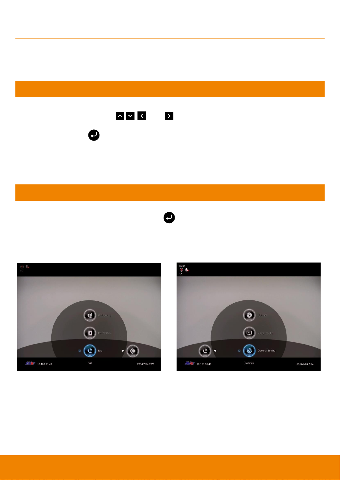
Home Screen
There are 2 selections divided on the Home screen: Call and Setting. Simply use the navigation
buttons to move between selections and press to confirm the selection. You can easily place a
call and select the site contact either in Dial, Phonebook or Call History. You can easily setup up the
system in General Setting, Video/Audio, and Network. The administrator can set a security
password to prevent changes made to the system setting and WebTool access.
Configuration Icons
Menu function is divided into 2 parts – Call and Setting.
Call function is included Dial, Phonebook and Call History.
Setting function is included General Setting, Video/Audio, and Network.
23
Page 28

On the upper left-hand corner of your home
screen, you may see camera and MIC
indications.
When camera is removed, “Camera
Disconnected” warning message is displayed
and screen is blue.
When is displayed on that screen, it
means far site remote can be operated by
remote controller.
is displayed indicating microphone is mute.
Try pressing the mute button on microphone or
remote controller to unmute it (LED indicator on
microphone turns blue).
On the lower left corner of your home screen,
you can find current WAN IP address.
Camera and MIC Icons
WAN Address
24
Page 29
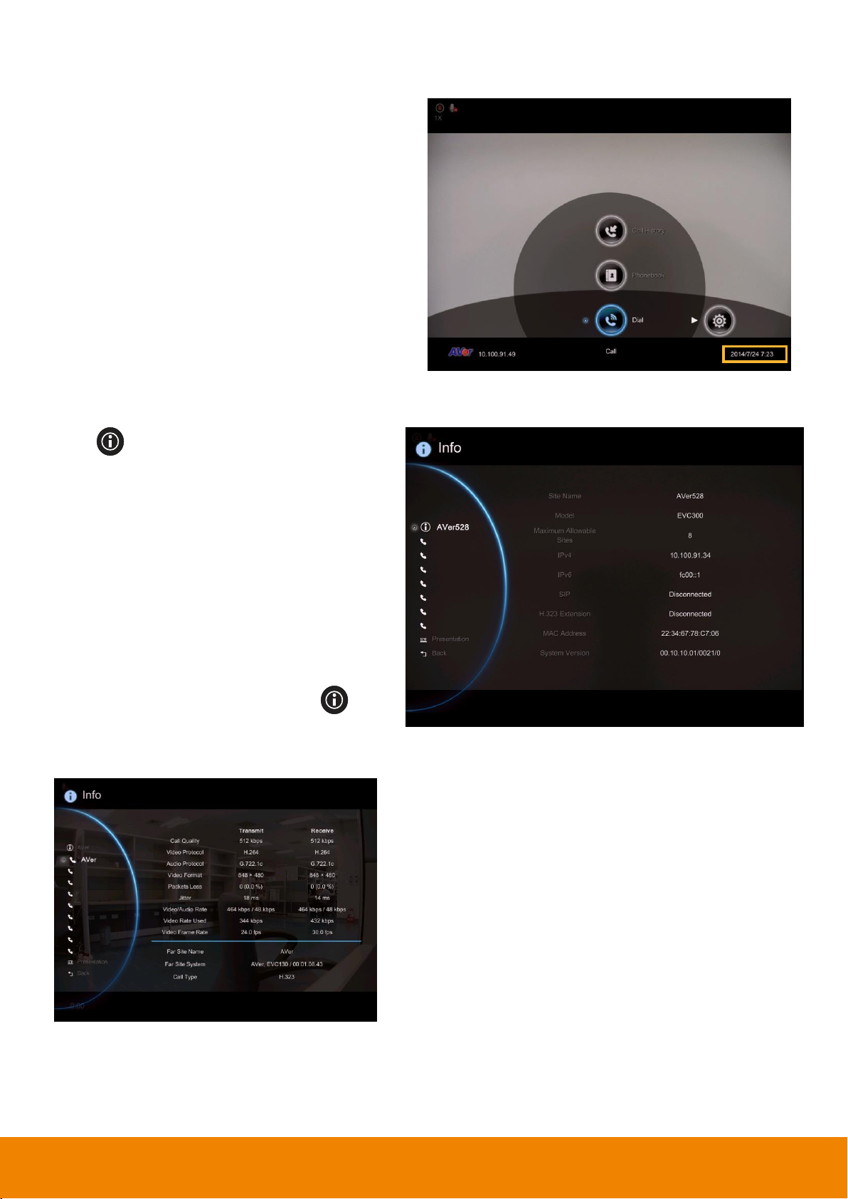
On the lower right corner of your home screen,
you can find the current Date and Time once
system sets up properly.
Press (Info) button to switch to system
information page.
The System Info shows you the relative
information about your EVC main system
including Site Name, Model name, Maximum
Allowable Sites, IP Address, MAC Address
and System Version.
Also, you can view call status while call is
connected.
1. Make a call.
2. When call is connected, press (Info)
button.
3. Select the call and you should see the
current call status.
Real-Time Clock
System Info
25
Page 30

Dial selection allows you to enter dial screen and
make a call.. Press button on the remote
controller has the same effect.
Use the number keys on the remote controller to
enter the IP address or number or SIP URI
(sip:username.password@host) you want to call.
AVer remote controller supports alpha-numeric
operation, press numeric key multiple times to
select the alphabet or symbol.
[Note] Press button and hold can switch
between numeric mode(123) and alphanumeric
mode(ABC/123).
AVer EVC supports H.32, SIP, SIP Only Voice
calls. H.323 is commonly used to communication
to other videoconferencing room systems. SIP is
commonly used to communicate with other VoIP
devices. SIP Only Voice is used when other
conference site could not recognize EVC video
code, only transfer voice. Use the button to
select which type of call type you want to make
then press to confirm.
[Note] H.322 and SIP call type can be existed in
a same conference call meeting.
Dial
Call to
Call Type
26
Page 31

For the Call Quality selection, enter the desired
call quality (or network bandwidth) from the
drop-down list (default or 64K up to 4M bit per
second).
Select the “Call” on the Dial configuration
screen then press to make a call.
Make sure the network jack is plugged in and
network is working properly before making a call;
otherwise, the “Network Jack Unplugged”
information will appear. Click “OK” to reconfirm
the network connection.
Call Quality
27
Page 32

1. When in multi-point call conference, press
button(Hang up) on remote control
and a call-point list screen is pop-up.
2. Use the ▲ and ▼ buttons to select which
you want to disconnect and press . To
end the meeting, select Disconnect All.
3. You will notice the site names in the
meeting are color coded. If you are not sure
of which name you want to disconnect, refer
to the color of the frame.
4. In multiple call conference, you can choose
to hang out which call.
Hang up the call
Video Layout
Video layout on multisite connections is shown as following figure.
When only 2 points connection with content sharing, user can have 7th layout to choose which screen layout
shows content sharing and far sit view only.
28
Page 33

Phonebook allows you to create and edit contact
information, group contacts by category, search
contacts then make a call. The group and
contact (site) name in the directory will be sorted
in alphabetical order. You may use the WebTool
to edit or import the phonebook entries too.
Select Phonebook and press .
Select Group and press .
If you have lots of contacts, it is better to
categorize them to groups such as client,
vendor, company, branch, etc. to make the
lookup easier.
Phonebook
Group
29
Page 34

In the Group configuration screen, Press “Red”
button on the remote controller to pop up the
group dialogue box.
Input Group Name: Enter a name for the
group.
Input Mailto: Enter an email address for
receiving files upload notice.
Input Google Account: Enter a google
account to receive file upload notice from
the mail account that you have setup in
“Input Mailto”.
Input Google Password: Enter the google
account’s password the you have setup in
“Input Google Account”.
After enter all information, select “Save” to save
the new group. Or select “Cancel” to exit the
dialogue box.
The new group name will be saved and
displayed in the group list.
Create a New Group
30
Page 35

Press “Yellow” button on the remote
controller and enter the group name that you
want to search.
If the name you enter has not been created, the
system will show you “No Group Available”,
please search again.
If the Group data are over one page, you can
also press “Green” button or “Blue”
button to Page Up or Page Down.
Search a Created Group
31
Page 36

Select Phonebook│Group and press .
Select the name you want to modify in the group
list.
Select “Edit Group” and press .
Modify the information and select “Save” to
save the revised information.
Auto Upload: Enable/disable uploading the
record and snapshot files to google drive
automatically. When a red “X” is displayed, it
means upload function is not setup yet. Please
go to EVC system’s web page to setup upload
function(also see Web Configuration).
[Note] 1. Recording and snapshot files upload
only available for group call.
2. Uploading will be active at 1 hour later after
conferencing call finished and there in no other
conferencing call or operation on EVC system in
a 1 hour.
If you have revised group name, then, the new
group name will be displayed in the group list.
Edit Group
If the revised name is the same as the saved name, the revised name will be ignored.
32
Page 37

Select Phonebook│Group and press .
Select the Group name you want to add to
Contacts List.
Select “Edit Group” and press .
Confirm the Group Name what you want to add
to the contacts list and then select “Contacts
List”.
Add Contact from Group List
33
Page 38

In the Group Site list, select the item that you
want to add to the contracts list and then press
“Red” button on the remote controller to
save the selection.
Select “Save" to save the Group name and
added site to the contacts list.
The selected Group name and added site will be
added into the contacts list.
34
Page 39

Select Phonebook│Group and press .
Select the name you want to remove in the
group list.
Select “Delete Group” and press .
Select “Yes” to remove the selected group
name and “Cancel” to cancel group name
deletion.
The selected group name will disappear in the
group list when deleted.
Select Phonebook│Group and press .
Select the name you want to select in the group
list.
Select “Group Call” and press .
Delete Group
Group Call
35
Page 40

EVC system will star to call the site point in
selected group. To stop calling, select Cancel.
Select Phonebook│New Site and press
.
Select the Group name, if you don’t want to
add the entry into a group, please select
“Non-Group” item.
Select Site Name box. Enter the site name
with the remote controller and press .
New Site (Contact in Phonebook)
New Site allows you to create and edit the information to each site.
Add New Site
36
Page 41

Enter the used call type information either
H.323 or SIP.
Select the desired call quality value in the
drop-down list.
Select “Save” to store the newly added site
contact.
37
Page 42

Select Phonebook│Contacts List and press
.
Select the contact you want to modify and
press .
Select “Edit Site” and press .
In the Edit Site screen, you may change the
Group name, Site Name, H.323. SIP and Call
Quality.
After making the changes, select “Save” to
apply the new changes or “Cancel” to reserve
the original settings.
The saved changes will be shown in the Group
Site list.
Edit New Site
38
Page 43

Select Phonebook│Contacts List and press
.
Select the contact you want to delete and
press .
Select “Delete Site” and press .
Select “Yes” to remove the selected contact
and “No” to cancel contact deletion.
The selected contact will disappear in the
Group-Site list when deleted.
Delete New Site
39
Page 44

Contacts List shows you all of the contacts
that you have created and saved. You can
select the contact from the Contacts List
directly for modifying or deleting. In the
Contacts List configuration screen, you can
also use the “Yellow” button on the
remote controller to search the contact that
you want. If the Group-Site over one page, you
can also press “Green” button or “Blue”
button to Page Up or Page Down.
Select Phonebook│Favorite and press .
Select which line (0~9) do you want to save
the favorite contact and press .
Select the contact from the pop-up Group Site
list and press “Red” button on the remote
controller to save the selection.
Contacts List
Favorite
AVer EVC allows you save up to 10 most used contacts in the favorite list.
40
Page 45

The item selected will be added into favorite
list.
You can make the calls from the favorite list
#(0~9) which you have set the favorite list, to
press and hold the button #(0~9) via remote
controller in Home menu screen.
View the phonebooks are downloaded from
LDAP server.
The Call History allows you to check the
incoming/outgoing calls made and their status.
You can also make a call by selecting it in the
Call History list.
Online Phonebook
Call History
41
Page 46

Select Call History and press .
The Call History will show you the IP address or
the Site name with call type, Call Date/Time,
Duration, and Call status. Refer to the table
below to check the call status.
Call Status
Answered
Failed
IN
OUT
Select Call History and press .
Use the and buttons to move the
selection and scroll up and down in the call
history list.
Press and select “Call” to make a call. Or
press button on the remote controller to
make a call.
The call will be connected.
Call Status
Make a Call From the Call History
42
Page 47

Select Call History and press .
Use the and buttons to move the
selection and scroll up and down in the call
history list.
Press and select “Save” to pop-up
contact editing form. All relative information
has filled in the contact form already based on
the selected call entry from the Call History.
Confirm the Group selection then select
“Save” to save the call entry into your contact.
Make a Contact from the Call History
You can also save the call in/out information into your contacts list.
43
Page 48

The General Setting allows you to modify system
setting, authority of administrator, monitor
setting, and adjust date and time.
Select General Setting│Call Settings and
press .
Select Auto Answer and press . In the
Auto Answer drop-down list, select “OFF” to
turn off Auto Answer. “ON” to answer the call
automatically and “First Call Only” to
automatically answer the first call and answer
or reject other incoming calls manually. “First
ON with MIC Mute” will automatically answer
the first coming call but local site is in mute
status; the caller site couldn’t hear any sound
from local site.
If you are already in a conference, even if the
Auto Answer is turned on, you also need to
accept the next call manually.
General Setting
Call Settings
Call Setting set the system to enable/disable auto answer, set the default call quality, and
enable/disable Advanced Encryption Standard which ciphers the data to protect against unauthorized
data access.
Auto Answer
44
Page 49

EVC main system supports 64K,128k, 256k,
384k, 512k, 768k, 1024k, 1152k, 1472k,
1536k, 1920k, 2048k , 3072k, 4096k selection
for default call quality. By default, it is set to
512k.
Advanced Encryption Standard (AES)
encrypts the data that is being transmitted
during a video conferencing to provide
protection against unauthorized data access.
Encrypted data can only be read with the
device that also supports the AES standard. All
parties on the call must support AES to use
this feature, or else the data will not be
encrypted.
Select General Setting│Call Settings and
press . Select the Enable AES check box
to active this function.
Quality of Service (QoS) provides different
priority data flows to guarantee a certain level
of performance in video conferencing data
flow. To activate QoS, select General Setting
│
Call Settings and press . Select the
Enable QoS check box to active this function.
By default, this function is disabled.
Default Call Quality
Enable/Disable AES
This function may be restricted and unavailable in some countries.
Enable/Disable QoS
45
Page 50

Enable/disable the call duration showing, by
default, this function is enabled.
This function allows you to specify the
maximum bandwidth of the outbound and
inbound calls. AVer EVC system supports up
to 36M.
During the video conferencing, the EVC
system will detect which connected point is
talking and show the video of talking point into
enlarge screen view.
Show Call Duration
Max. Transmitting/Receiving Bandwidth
Voice Activated Layout Switch
[Note]
1. When function of Voice Activated Layout Switch is enabled, the multiple connections must over 3 points.
46
Page 51

Select General Setting│System Settings and
press . The site name is represented as
name of this EVC system. Enter the site name
as you wanted.
Select General Setting│System Settings and
press .
EVC main system supports up to 22 languages
for your selection. Select the language from
the drop-down list directly and the language for
the system will turn into the selected language
automatically.
2. When voice activate function is disabled, the screen is displayed the video of first connected call.
3. In Figure 1, the layout 2 ,3 and 4 are displayed the talking point at largest video screen area and rest of
points are displayed in small video screen area. If connecting point doesn’t enable “Voice Activated
Layout Switch” function, it will display in small screen.
4. In Figure 1, the layout 4 is displayed talking point on largest video screen area. If Voice Activated Layout
Switch doesn’t enable, the largest video screen area is displayed video of local site.
For example:
Figure 1
System Settings
System Settings allows you to e nter or change your system’s site name which will appear on the
screen during the call session for the other party to identify you, set Language, the time for Auto
Power off and enable/disable Keypad Tone function for your main system.
Site Name
Language
47
Page 52

Select General Setting│System Settings and
press .
Select the time from the Auto Power Off
Mode drop-down list (OFF/30Minutes/
1Hour/2Hours/3Hours/4Hours). Disable this
function, please select “OFF”. The function will
completely turn off the system once you have
set the auto power off time. To turn on the
system you need to press the Power button on
the EVC main unit again.
Select General Setting│System Settings and
press .
Select the Keypad Tone check box to enable the
tone sounds. By default, this function is enabled.
Auto Power Off Mode
Auto Power Off Mode allows you to set the time to power off your system automatically after idling.
Keypad Tone
Keypad Tone allows you to enable/disable tone sounds when you are dialing a number using the
remote controller.
48
Page 53

Select General Setting│Administrator and press
.
Here allows you to enable administrator authority
of Web Tool. When you access to Web Tool, a
password is required. The default password is
“1234”.
Select General Setting│Administrator and press
.
Here allows you to enable authority of system
administrator. When you want to setup system, a
password is required. The default password is
“1234”.
Select General Setting│Administrator and press
.
Here allows you to change password of system
administrator.
Administrator
Enable Web Admin
Enable Admin
Change Admin. Password
49
Page 54

Select General Setting│Administrator and press
.
Here allows you to change password of EZDraw.
EZDraw password is used when user use
EZDraw on tablet to connect to EVC system.
EVC system support up to 10 users to connect to
EVC system by EZDraw.
The default password is “1234”
Select General Setting│Administrator and press
.
Here allows you to enable function of VCLink
and ScreenShare.
Select General Setting│Administrator and press
.
Here allows you to change password of VCLink
and ScreenShare. The default password is
“1234”
Change EZDraw Password
Enable VCLine/ScreenShare
Change VCLine/ScreenShare Password
50
Page 55

Select “Save” located next to “Save System
Log” to save the system log into your USB Flash
drive.
After the file is saved, select “OK”. Remove the
USB Flash drive and insert it into your
computer’s USB port. Located the file
message.tar.gz and send it to the technical
support team.
Select this function check box to enable firmware
updated notice function. By default, this function
is enabled.
Save System Log
If you encounter unknown issues and are unsure of how to troubleshoot the unit, sending us the
saved system log data to help us solve your problem faster.
Insert a USB Flash drive into the USB Port(on front panel)) of the EVC main system.
Firmware Update Notice
51
Page 56

Select the “Far End Camera Control” check box
to enable the far site to control your camera. By
default, this function is enabled.
Wake-on-LAN is an Ethernet computer
networking standard that allows your computer
to be turned on or awakened by a network
message. By default, this function is disabled.
Far End Camera Control
Wake-On-LAN (WOL)
52
Page 57

Select General Setting│Monitor and press
.
Select the Monitor Aspect Ratio (Auto
/4:3/16:9) that you want from the drop-down
list and press . If you want the system to
detect the right setting automatically, please
select “Auto”.
Select the Screen Saver time (OFF/10
Minutes/20Minutes/30Minutes/60Minutes)
from the drop-down list and press . You
can select “OFF” to disable this function or
define a standby mode time.
TV Underscan
For older type TVs/CRT monitors, this function
can help to auto adjust screen view when the
GUI is exceeded the monitor view range.
Monitor
EVC main system allows you to connect dual monitor. In the Monitor configuration screen, you can
configure the Aspect Ratio and Screen Saver to each monitor.
The screen will turn black when the system is in standby mode. Press any button on the remote
controller to wake up the system.
53
Page 58

HDMI1 Compatible Offset Frame
To adjust screen position if the screen display
is not in center.
Turn on white border around image
Enable/disable the white borer around image
window during video conferencing. The default
is enabled.
Select General Setting│Date and Time and
press .
Select the Date Format (yyyy-mm-dd/
mm-dd-yyyy/dd-mm-yyyy) you prefer from the
drop-down list.
Date and Time
Date and Time allows you to set the Date and Time formats, adjust the time setting and change the
time zones around the world and countries.
Date Format
54
Page 59

Select General Setting│Date and Time and
press .
Select the Time Format (24-hour/12-hour) you
prefer from the drop-down list.
Network Time Protocol (NTP) is a protocol that
is used to synchronize computer clock times in
a network of computers. Select the Enable
NTP check box to make your main system time
the same as the network time.
The Network Time Protocol (NTP) allows
administrators to synchronize all network
computers to a main server. This keeps all
network machine clocks on the same time.
Enter the NTP Server name that you want to
follow.
Time Format
Enable NTP
NTP Server
55
Page 60

Timezone allows you to adjust the time when
you are in a different country or area so that
you can keep the same time with your original
area. Most of the time zones on land are offset
from Coordinated Universal Time (UTC) by a
whole number of hours (UTC-12 to UTC+14).
Enter the date and time including year, month,
day, hour and minute that you want to show on
the present system.
Select “Apply” to active your settings.
Timezone
Year and Hour
56
Page 61

The Reset System allows you to reset your
main system to factory settings, which will
clear phonebook entries and call history. Make
sure to back up the information before
resetting the system.
Default Setting Reset: LAN configuration,
video/audio codec selection, call settings and
so on will be reset. Click “Yes” to reset your
system to factory default values.
Clear Phonebook: All the phonebook entries
saved in the system will be deleted.
Click “Yes” to delete all content of your
phonebook.
Reset System
57
Page 62

Clear Call History: All the incoming and
outgoing call records will be deleted. Click
“Yes” to delete all calling information of the call
history.
EVC300/EVC350 can purchase license to
increase call-point up to 10 call-points. To
purchase license, please contact your sales
dealer.
[Note] EVC900 is a 10 call-points device, the
license purchase is not allowed.
Select Add License to enter license serial
number.
Press keypad button on remote and enter the
license serial number. After entering, select
OK to back to License enter page. Then,
select Activate to register the license.
You will see the license serial number list in
Activate License section.
To enter another license serial number, follow
above steps.
[Note]
1. License serial number is capital sensitive.
2. One license only for one EVC device.
License
58
Page 63

To use Skype for Business function, please
purchase the license. Please contact your
sales dealer for license purchasing.
Select Add License to enter license serial
number.
Press keypad button on remote and enter the
license serial number. After entering, select
OK to back to License enter page. Then,
select Activate to register the license.
[Note]
1. License serial number is capital sensitive.
2. One license only for one EVC device.
You will see the license serial number list in
Activate License section.
To use Skype for Business function, go to
Home > Network > Skype for Business.
Skype for Business License
[Note]
1. EVC300/EVC350 support up to 3 sites of Skype for Business. EVC900/EVC950 up to 4 sites of
Skype for Business.
2. Transmit to Skype for Business side Content XGA (1024x768), up to 5fps
59
Page 64

You can select the layout for call conference.
There two type of layout – Layout without
content and Layout with content.
Layout without content: Only display call
video, no content share screen.
There 4 layouts can be chosen. During the call
conferencing, the display layout will be the layout
that you has chosen.
Layout with content: display call video and
content share screen.
There 6 layouts can be chosen; but only 2
layouts include content share screen. During the
call conferencing, the display layout will be the
layout that you has chosen.
Default Layout
60
Page 65

PIP Display Time: When conference call is
connected, screen is displayed in PIP mode.
You can manually setup PIP mode display time.
The default is 5 seconds.
61
Page 66

In Video/Audio configuration screen, you can
set the MIC gain level, select the preferred video
and audio codecs and adjust the camera
functions.
Select Video/Audio│Camera and press .
Select the White Balance type from the drop
down list. EVC main system supports up to 5
types of white balance for your selection.
Video/Audio
Camera
Camera allows you to set the White Balance, Exposure, Sharpness, and Frequency for your
camera.
White Balance
Whit balance is a camera setting that adjusts for lighting in order to make white objects appear white
in photos.
Auto: Most cameras default to automatic white balance. It makes white objects bright white and alter
all the other colors to match.
Cloudy: You can use the Cloudy white balance setting instead of auto on a cloudy day. This allows
the camera to compensate for blueness in the shadows, warming up the scene to better match what
your eye would see.
Daylight: You can use Daylight settings only when shooting in very bright sunlight, as it can produce
bluish results on overcast days.
Fluorescent: You can use Fluorescent setting to cancel out the green or blue cast, which can
produce sickly-looking results on human skin.
Tungsten: This setting assumes a color temperature of around 3,200k and is suitable for most
tungsten lamps that normally emit a yellow light. This is usually used to correct for the same color cast.
62
Page 67

A photograph’s exposure determines how light
or dark an image will appear when it is been
captured by your camera. Select the exposure
level you prefer from 1 to 9 or auto.
Select the correct frequency setting
(Auto/50Hz/60Hz/OFF) form the Frequency
drop-down list.
Adjust camera sharpness. The more sharpness
the screen image more easy has noise.
Exposure
Frequency
Sharpness
63
Page 68

When camera is handed at up-side-down
position, enable Camera Upside-down to flip the
image view.
One Shot: The camera only will do the focus
adjust at beginning..
Face Detection: The camera will adjust focus
base on the face that is nearest to camera. The
camera only will do the focus adjust at
beginning. You can press button on remote
to re-force the camera to do the focus adjusting.
Auto Focus: The camera will adjust focus
automatically.
Standard: No any effect adjustment on screen
view.
Moire-free: To reduce moire if moire screen is
happened.
Camera Upside-down
Camera Focus Mode
Scene Mode
64
Page 69

Here allow you to enable 3D denoise function.
This function can improve image view in low
light environment. By default, the 3D denoise
is disabled.
Select Video/Audio│Microphone and press
.
Adjust the MIC Gain Level form the drop-down
list.
Enable 3D-denoise
Microphone
EVC main system allows you to adjust the MIC Gain Level up to 9 for proper MIC volume to improve
audio reception on the microphone (s).
MIC Gain Level
65
Page 70

Select the source of the microphone from the
MIC in, Audio IN with AEC, or Audio IN without
AEC. If you connect a microphone in AUDIO
IN port, we recommend selecting Audio in
selection to avoid the echo issue.
Send the audio through the audio device that
is connected at audio input port of EVC to
selected site(far, near, or both).
If MIC Input Source is MIC in, you can choose
far, near or both site can hear the audio sound.
If MIC Input Source is Audio in, only “far site”
can be heard the audio sound.
[Note] When audio input port is connected
with audio device and enable “Sending Audio
Via Line-in to” function, the AVer MIC is
disabled.
Send the audio through the device that is
connected at HDMI input port. You can choose
which site or both site can hear the audio
sound.
MIC Input Source
Sending Audio Via Line-in to
Sending Audio Via HDMI-in to
66
Page 71

This function allows you to hear own talking
voice during video conferencing through the
stream media device that is connected on
HDMI-2 port of EVC main unit.
In MIC Input Source, please select “MIC In”.
If the stream media device didn’t connect to
HDMI-2 port of EVC main unit, it will cause
howling when voice come out from TV or
speaker.
Broadcast Support(HDMI-2)
67
Page 72

Select Video/Audio│Video Codecs for Video
Codecs configuration, Video/Audio
│
Presentation Codecs for Presentation
Codecs, or Video/Audio│Audio Codecs for
Audio Codecs configuration and press .
Select the Video/Presentation/Audio
Codecs to specify the codecs you want to
support. While the EVC supports the H.323
standard coding algorithm, each codec has
unique properties and performs best given a
certain set of circumstances.
For Video: H.261,H.264, H.263+, H.263,
H.264HP, H264SVC
[Note]
1. H.261 is always mark by default.
2. H.264SVC only work with AVer EVC system
and default is disabled.
For Presentation: H.263, H.263+, H.264,
H.264HP, H264SVC
For Audio: G.728, G.722.1C, G.722.1*,
G.722, G.711
Video/Audio Codecs
You can specify the Video/Presentation/Audio Codecs in Video Codecs, Presentation Codecs,
and Audio Codecs configuration screens.
Please contact system administrator if you have any question on these codecs.
*:G.722.1/G.722.1C, licensed from Polycom®
68
Page 73

Network allows you to set the SIP Server,
Gatekeeper, Firewall and LAN
Configurations. Before configuring Network
and Firewall, please refer to page 69 –
Scenarios for LAN connection and follow the
instructions of your actual network connection
scenario.
Select Network│LAN Configuration and press
.
Configure the following relative items to setup
the LAN Configuration.
DHCP: Configure the system to automatically
obtain an IP address from the DHCP server.
Static IP: Configure the system to use the
assigned IP address. Select this when the
public IP address is available.
Network
LAN Configuration
AVer EVC supports IPv4 and IPv6 internet protocol for your configuration. IPv4 is the most widely
deployed internet protocol used to connect devices to the internet. IPv4 uses a 32-bit address scheme,
written in decimal as four numbers separated by periods. Each number can be zero to 255. For
example, 192.168.0.1 could be an IP address.
Obtain IP Address
69
Page 74

Show the current IP address; enter into when
you need to configure your IP address
manually.
Show the designated IP address routing prefix;
enter the subnet mask address when the
system does not automatically obtain the
subnet mask
A gateway is a network point that acts as an
entrance to another network. Enter the
gateway address when the system does not
automatically obtain the gateway.
Your IP address is
Subnet Mask
Default Gateway
70
Page 75

Domain Name System (DNS) servers convert
human friendly names (for example:
www.example.com) to IP addresses
(218.77.272.166) that let machines be found
on the network. The preferred DNS server is
the one your computer asks first. The alternate
is a backup. Enter the Preferred and
Alternated DNS Server address.
After finishing all settings, select “Apply” to
active the changed settings.
Select Network│LAN Configuration (IPv6)
and press .
Configure the following relative items to setup
the LAN Configuration (IPv6).
Preferred/Alternate DNS Server
IPv6
IPv6 is an evolutionary upgrade to the Internet Protocol. IPv6 will coexist with the older IPv4 for some
time. IPv6 addresses are 128-bit IP address written in hexadecimal and separated by colons. An
example IPv6 address could be written like this: 300E:1389:3030:72EB:1D71:414B:1079:6AF3.
Some types of addresses contain long sequences of zeros that can be compressed (the address of
fc00:0000:0000:0000:0000: 0000:0000:0001 can be compressed to fc00::1.
71
Page 76

Static IP: Configure the system to use the
assigned IP address. Select this when the
public IP address is available.
Auto: Obtain the dynamic IP address
automatically.
Show the current IP address; enter into when
you need to configure your IP address
manually.
Prefix Length allows you to place as many
IPv6 devices as the underlying network
medium allows.
Obtain IP Address
Your IP Address is
Prefix Length
72
Page 77

After finishing all settings, select “Apply” to
active the changed settings.
Select Network│Advance Network and press
.
Enable 802.1x: Enable/disable 802.1x
protocol. IEEE 802.1X is an IEEE Standard for
port-based Network Access Control (PNAC).
It provides an authentication mechanism to
devices wishing to attach to a LAN or WLAN
.
Identity: Enter the ID for 802.1x
authentication.
Password: Enter 802.1x’s authentication
password.
Click Apply to save and active the settings.
Advance Network
Configure 802.1x and VLAN settings.
EAP 802.1x
73
Page 78

Enable VLAN: Enable/disable VLAN function.
A virtual LAN (VLAN) is any broadcast
domain that is partitioned and isolated in
a network at the data link layer.
VID(802.1q): Enter port for VLAN.
Priority(802.1p): Assign VLAN packet’s
priority.
Click Apply to save and active the settings.
Select Network│Firewall and press .
Configure the following relative items to setup
the Firewall.
By default, the system communicates through
TCP/UDP ports in the range from 30000 to
30299. You can specify the range for your
specific network environment.
VLAN
Firewall
Configure the following items to setup the Firewall.
TCP/UDP Ports
You must configure your firewall to allow inbound/outbound traffic through “UDP (port 1719)”/ “TCP
(port 1720)” for H.323 call setup.
74
Page 79

AVer EVC supports NAT systems that use the
internal IP addresses to communicate with
other devices outside the LAN.
The NAT public address must be entered
when you enable the feature on NAT
configuration.
Select Network│SIP and press .
Configure the following relative items to setup the
SIP.
NAT Configuration
NAT Public (WAN) Address
SIP
Session Initiation Protocol (SIP) allows you around the world to communicate using your supported
devices over the Internet.
75
Page 80

Enter the SIP site name for others to identify.
The SIP site name may be the same or different
then the domain for Web activity.
Select internet protocol check box to enable IPv4
or IPv6 protocol using.
SIP Site Name
Inter Protocol
76
Page 81

TCP: TCP is connection oriented. Once a
connection is established, data can be sent
bidirectional.
UDP: UDP is a simpler, connectionless Internet
protocol. Multiple messages are sent as packets
in chunks using UDP.
TLS: TLS is a cryptographic protocols designed
to provide communications security over
a computer network. SIP payloads will be
encrypted to prevent malicious or unwanted
modifications. NAT-traversal can be achieved by
TLS connections since SIP payloads will not be
altered by NAT-enabled routers.
Change this value only if you use specific
settings in your network system. By default, the
SIP port is set to 5060.
SIP Transport Protocol
Select the SIP Transport Protocol type from the drop-down list for using. There are two types of
Internet Protocol (IP) traffic. They are Transmission Control Protocol (TCP) and User Datagram
Protocol (UDP). To ensure proper connection, verify if both calling parties are using the same
transport protocol. By default, it is set to UDP.
SIP Port
77
Page 82

Enable presentation sharing function in SIP. It
allows you to share the presentation file screen
to other caller in video conference meeting.
If connection is not so stabled, use TCP mode
can offer a reliable connection to prevent
unexpected disconnection and behaviors due to
packet losses.
Through SRTP, RTP payloads will be encrypted
to prevent sniffer, and hence secure
communication between users.
STUN (Session Traversal Utilities for NAT) is a
standardized set of methods and a network
protocol to allow an end host to discover its
public IP address if it is located behind a NAT.
Enter IP address of SIP NAT traversal server.
BFCP
Enable SRTP
STUN Server
78
Page 83

Enter port number of STUN server.
Mark to enable STUN server function.
1. Select Network│SIP Configuration and press
.
2. Configure the following relative items to setup
the Server.
STUN Port
Enable STUN Server
SIP Configuration
A typical SIP session involves a client requesting a session with a SIP server. After the request is
received, the SIP server returns a response to the user indicating the availability of the session.
79
Page 84

Select Operating Mode and press to
select the mode from drop-down list.
Become a Client: Register EVC main system
to SIP external server.
Become a Server: Set EVC main system as a
SIP server.
[Note] Only allow the users are registered on
EVC300 / EVC900 SIP server can make a
connection.
OFF: To deactivated using SIP.
Select User Name and press to enter
user name.
Select Authorization Name and press to
enter authorization name.
Operating Mode
Become a Client: Select Operating Mode is “Become a Client” in SIP Configuration. Then, enter the
following information to register to SIP server.
User Name
Authorization Name
80
Page 85

Select Password and press to enter using
password.
Registrar Server accepts registrations from
users and places these registrations, (which is
essentially location information), in a database
known as a location service. Enter the
Registrar Server name that you want to use.
Proxy Server is computing device (typically a
server) that interfaces between data
processing devices and others within a
communications network. These devices may
be located on the same local area network or
an external network. Enter the used Proxy
Server name.
Password
Registrar Server
Proxy Server
81
Page 86

Select “Account Active” check box and press
to activate/deactivated.
Next, go to Register button and press to
register to the SIP server.
Select authenticate way to authorize SIP client.
Anonymous: No password required for any SIP
client.
Password: Password is required for SIP client
to connect SIP server. Set the password in
Password column.
When authentication mode is Password mode, a
password is required to be set. The default
password is “1234”.
Account Active
Become a Server: Select Operating Mode is “Become a Server” in SIP Configuration. Then, enter the
following information to be a SIP server.
Authentication Mode
Password
82
Page 87

The SIP server’s ID that wants to connect. The
EVC300 / EVC900 default server ID is “1000”.
To make a 1 to 1 call meetings through the
registered SIP server to other EVC system,
EZMeetup, or 3rd party conference device. EVC
supports five group ( 1 to 1) call meetings.
[Note]
1. Callers and receivers need to be registered
on same SIP server and are list in Registered
Users’ list.
2. EVC(SIP server) must power on and setup in
SIP server mode.
3. EVC(SIP server) is a call meeting bridge and
host session in background.
4. Make sure the TCP/UDP ports(30299 ~
30699) of router and EVC are opened.
5. Make sure the internet bandwidth is enough
and will not affect performance of standard
conference call.
6. The BFCP content sharing only support UDP
protocol in Client to Client call.
Server ID
Client to Client
83
Page 88

List all registered SIP client.
Select Network│Gatekeeper and press .
Configure the following relative items to setup
the Gatekeeper.
Specify the name that gatekeepers and
gateways can use to identify this system. Enter
the name; the gatekeeper will use this name for
identification.
Registered Users
Gatekeeper
The Gatekeeper in AVer EVC serves the purpose of translating services from E.164 IDs to IP
addresses in an H.323 network.
H.323 Name
84
Page 89

Enter a numeric value for the gatekeeper to
identify your system further.
Enter the IP address for the gatekeeper server.
Select the “Authentication” check box to
activate gatekeeper authentication if gatekeeper
requires authentication.
User Name and Password: Enter the user
name and password for gatekeeper
authorization.
H.323 Extension
Gatekeeper Address
Authentication
85
Page 90

Select this check box to Activate/deactivate
gatekeeper.
If you want to enable the H.460 Firewall
Traversal, please set the following ports in port
forwarding in your firewall before start installing
your EVC.
Port
Function
Type
1719
Gatekeeper
UDP
1720
H.323 Call
setup
TCP
30000~30699
Signaling and
Control for
audio, video,
content, and
data/FECC
TCP and UDP
80
HTTP Interface
(WebTool),
EZDraw
TCP
23
Telnet
TCP
5060,
5061
SIP
TCP and UDP
TCP
5000, 50001
ScreenShare
VCLink
TCP
Connect to Gatekeeper
Make sure to setup the Gatekeeper before setting up the Firewall.
Enable H.460 Firewall Traversal
Make sure your gatekeeper supports H.460 Firewall Traversal before enabling it.
86
Page 91

Select Network│Test Utilities and press .
Select Run to start testing.
Wait until it finishes the network test. The check
mark will appear if the network test is successful.
If it fails, save the report in a USB flash drive and
contact our technical support.
To ping or traceroute the far site device.
Select Network│Test Utilities and press .
Select Test Command and press .
- Ping: Ping is used to test the reachability of
a host on an Internet Protocol (IP) network,
and to measure the round-trip time for
messages sent from the originating host to
a destination and echoed back to the
source.
- Traceroute: traceroute is displayed the
route (path) and measuring transit delays
of packets across an Internet Protocol (IP)
network.
IP Address: Enter the IP address of device that
user wants to ping or traceroute.
Finally, select Run to start ping or traceroute.
Test Utilities
Network Test
This feature tests the network ability between local and far site.
Test Command
87
Page 92

Select Network│Skype For Business and
press .
Account/Password: Enter your Skype for
Business account and password.
Enable Server: Disable to go the Office 365
online registration process, Enable to go
on-process process.
Registrar Server: Front End Server, the Front
End Server is at the core of any SFB Server
2015 deployment. It provides the links and
services for user Authentication, Registration,
Presence, Address Book, A/V Conferencing,
Application Sharing, Instant Messaging, Web
Conferencing and Dial-in over PSTN.
Proxy Server: Edge Server , the Edge Server
(or Edge Pool) sits on the perimeter of your
organization and its role is to enable secure
remote access to the internal (On-Premise)
Skype infrastructure. The Edge Server also
enables 'Federation' with external organization,
thus providing secure communications.
[Tips] 1. Note that in a Microsoft environment,
the Proxy server and the Registrar server are
always the same server.
2. User can make a call from SFB contactor list.
(Phonebook > SFB Contacts)
Remember me: To memorize the Skype for
Business account.
Click “Register” to register the Skype account.
After registering, far site can enter the registered
Skype for Business account to call to EVC
system.
Skype for Business
Setup the Skype for Business account for SFB call.
[Note] **EVC supports Lync 2013 and Skype for Business2015.
[Tips]
both see live view and presentation contents.
[Note]
Business, AVer will update the products’ development components to support the new version. AVer will
indicate which versions of Lync/Skype for Business are supported in the firmware release note of known issue,
according to system compatibility with MIS-SIP. AVer cannot guarantee functionality and compatibility for
software versions not listed in the firmware release note of known issue.
During SFB call, the SFB site only can see one streaming of presentation or live view. Only EVC site can
When Microsoft publishes a new version of MS-SIP, the source program material for Lync/Skype for
88
Page 93

Select Network│iSCSI and press .
To connect to iSCSI server on network.
Enter the iSCSI server’s IP, Port, Target Name,
Username, and Password.
Select “Connect” to make a connection to iSCSI
server. To disconnect, select “Disconnect”.
After connecting, the total capacity and used
capacity will be display.
Mark “Enable iSCSI after power on”, the iSCSI
will be connected when EVC unit is power on.
iSCSI
89
Page 94

Web Configurations
You can use the internet browser to access your AVer EVC system through a LAN RJ-45 cable to
setup a AVer EVC system remotely. You can also access the Phonebook to add, edit and delete
entries, view and download the call history, update the system, and restore your previous settings. For
web configurations, your AVer EVC system default IP address is: 192.168.0.1.
Please change your EVC’s IP address at the start.
Using the WebTool
Enter your EVC’s IP address in the URL field. You will need to enter admin password to log in.
In WebTool login screen, user can select the Language of Web Tool and enter the password, click
Submit button to login.
In the WebTool, there are some functions are different from your AVer EVC. And, those functions will
be described in following.
Default password is 1234
90
Page 95

After login, user should see the video screen of local site.
is indicated in background view mode. is indicated in live view mode.
Click icon can call out on-screen remote controller. You can use mouse to click the on-screen
remote controller to operate functions on WebTool.
Click button can switch to numeric pad and phonebook button.
Click button can switch back to navigation buttons.
91
Page 96

In the WebTool page, you can access the following:
Phonebook
Dial
Call History
Video/Audio
General Setting
Network
You can use the mouse to click the specified icon for a selection.
In WebTool, all functions are same as on EVC system.
92
Page 97

1. Locate and open the file using MS Excel
and select Office XML Handler to create a
schema based on the XML source data.
2. Edit the file.
3. Make sure to save the file as XML Data so
it can be uploaded back to the system.
Phonebook
Edit and Save
93
Page 98

1. Click Phonebook│Upload/Download.
2. The saving Phonebook data from AVer EVC
system dialogue box will appear.
3. Click “Save” to save the file.
4. After saving, you have to re-arrange your
browser to update your WebTool Phonebook
so that it can be the same as your EVC
system.
1. Click Phonebook│Upload/Download.
2. Click “Upload Phonebook” to upload
edited or added contents to your AVer
EVC system directly.
3. You can also click “Browser” to open the
Phonebook file .xml saved in your PC to
upload it to your AVer EVC system.
4. After completing upload, the contents of
Phonebook on your AVer EVC system will be
modified in time.
1. Click Phonebook│Upload/Download.
2. Click “Download History” to download call
history from to your AVer EVC system
directly.
Download Phonebook Entries
Download phonebook allows you to download contact data from your AVer EVC system.
Upload Phonebook Entries
Upload allows you to upload the data that you have edited or added from your WebTool to your AVer
EVC system.
You can also download the phonebook entries and upload them to another AVer EVC unit.
Download Call History Entries
Download History allows you to download call history list from your AVer EVC system.
94
Page 99

1. Click Phonebook│LDAP Setting
2. Enter the following information:
Server Address: Enter LDAP server IP
address.
Username: Enter username of LDAP
server.
Password: Enter password of LDAP
server.
Base DN: Enter LDAP object name / path.
After entering username and password
for authentication, it will start to search
from LDAP Base DN name / path.
Port: The port for EVC and LDAP server
to communicate. The default value is 389.
3. Click Apply to save the settings.
4. The download phonebook will be displayed in
“Online Phonebook” section.
Click Phonebook│Online Phonebook.
LDAP Setting
Setup your LDAP server then download your online phonebook.
Online Phonebook
To view the phonebook is downloaded from LDAP server. You can make a call directly and save into
contact list.
95
Page 100

1. Click Phonebook│Group
2. Click “New Group” to create a new group.
3. Enter the following information:
Input Group Name: Enter a name for the
group.
Input Mailto: Enter an email address for
receiving files upload notice.
Input Google Account: Enter a google
account to receive file upload notice from
the mail account that you have setup in
“Input Mailto”.
Input Google Password: Enter the
google account’s password the you have
setup in “Input Google Account”.
Auto Upload: Mark the check box to
enable auto upload function.
Authentication & Authorization Code:
Click “Apply” to get a authentication code
from your google drive account. After
clicking apply button, you need to enter
the google drive’s account and password.
Then, click “Login” and select “Allow” to
accept authorize on view and manage
your google drive. Finally, you will get a
authorization code. Copy the authorization
code to “Authorization Code” column.
4. Click Save to save the settings.
Upload Files Setting (Group Call Only)
You can setup to upload recording and snapshot files that are recorded and snapshot during the
group call to the google drive.
The files will be upload to google drive after conferencing call was finished an one hour later, but
during an one hour there are no any conference call and operations are made.
[Note] When upload file, the USB pen drive which has saved recording and snapshot files must plug
into EVC system.
96
 Loading...