

Page 1

Central Management System
CM3000
User’s Manual
V1.1.0.0
Page 2

COPYRIGHT
© 2013 AVer Information Inc. All rights reserved.
All rights of this object belong to AVer Information Inc. Reproduced or transmitted in any form or by any
means without the prior written permission of AVer Information Inc. is prohibited. All information or
specifications are subject to change without prior notice.
TRADEMARKS
“AVer” is a t radem a rk owned by AVer Inf orm ati on Inc . Other trade mar ks u sed here in for
description purpose only belong to each of their companies.
DISCLAIMER
No warranty or representation, either expressed or implied, is made with respect to the
contents of this documentation, its quality, performance, merchantability, or fitness for a
particular purpose. Information presented in this documentation has been carefully
checked for reliability; however, no responsibility is assumed for inaccuracies. The
information contained in this documentation is subject to change without notice.
In no event will AVer Information Inc. be liable for direct, indirect, special, incidental, or
consequential damages arising out of the use or inability to use this product or
documentation, even if advised of the possibility of such damages.
Page 3

The caution symbol is intended to alert the user of the importance of the particular
installation and operating instructions. Failure to comply may damage the system.
i
The information symbol is intended to provide additional information for the purpose of
clarification.
Manual Conventions
The following conventions are used throughout this manual.
Page 4

TABLE OF CONTENTS
CHAPTER 1 INTRODUCTION ........................................................................... 1
1.1 Upgrading to CMS GOLD Version ..................................................................................... 2
1.2 Dual Monitors setting ........................................................................................................... 3
1.2.1 Graphic card with ATi chipset ........................................................................... 3
1.2.2 Graphic card with NVIDIA chipset .................................................................... 6
CHAPTER 2 SOFTWARE INSTALLATION ....................................................... 7
2.1 Minimum System Requirements ........................................................................................ 7
2.2 Installing the CM3000 Software in Windows XP/Vista/7 ................................................ 8
CHAPTER 3 USING THE CMS .......................................................................... 9
3.1 Running the CMS Software ................................................................................................ 9
3.1.1 Using the Virtual Keyboard .............................................................................. 9
3.2 Using the CMS Application ................................ ............................................................... 10
3.3 Using the Monitor ................................ ................................................................ ............... 13
3.3.1 Using the Monitor Controller .......................................................................... 14
3.3.1.1 To Monitor CMS Server from iMatrix Server ......................................... 20
3.3.2 Familiarizing the Buttons in PTZ Camera Control Panel ................................ 22
3.3.3 Live Playback the Recorded Video ................................................................ 23
3.3.4 Viewing the GPS Data on the Monitor ........................................................... 25
3.4 Using the MiniCenter Viewer ............................................................................................ 30
3.4.1 Remote Backup ............................................................................................. 32
3.4.2 Remote Setup ................................................................................................ 36
3.4.2.1 System Setting ...................................................................................... 36
3.4.2.2 Camera Setting ..................................................................................... 40
3.4.2.3 Record Setting ...................................................................................... 42
3.4.2.4 Network Setting..................................................................................... 46
3.4.2.5 Schedule Setting ................................................................................... 49
3.4.2.6 Alarm Setting ........................................................................................ 51
To Setup Alarm Recording Setting ............................................................ 54
To Setup Alarm SOP ................................................................................. 55
3.5 Using the Alarm Center ..................................................................................................... 56
3.5.1 To Manage Live Alarm Event ......................................................................... 56
3.5.2 To Search the Alarm Event ............................................................................ 59
3.5.3 To Navigate the Alarm Information ................................................................. 63
Page 5

CHAPTER 4 CUSTOMIZING THE CMS SYSTEM........................................... 65
4.1 System Setting ................................................................................................................... 65
4.1.1 Using the System Controller .......................................................................... 70
4.1.1.1 Hardware Introduction ........................................................................... 70
Left Side .................................................................................................... 70
Rear Side .................................................................................................. 70
Familiarizing with System Controller Panel Buttons .................................. 71
4.1.1.2 Installation of System Controller ........................................................... 74
Connecting the CMS Server through the USB port ................................... 74
Connecting the CMS Server through the RS485 port ............................... 77
4.1.1.3 Operating the LCD Menu ...................................................................... 82
4.1.1.4 Familiarizing with LCD Screen .............................................................. 83
4.1.1.5 Switching to USB CMS Mode ............................................................... 84
4.1.1.6 Switching to 485 CMS Mode ................................................................. 85
4.1.1.7 To Select an CMS server ID in 485 CMS mode .................................... 86
4.1.1.8 Upgrading the Firmware of the System Controller ................................ 87
4.1.1.9 Locking System Operation .................................................................... 89
4.1.1.10 Center Mode Operation ........................................................................ 90
Select an Monitor Layout .......................................................................... 90
Select an Monitor ...................................................................................... 91
Call out the Alarm Center ................................................................ .......... 92
Call Out the Mini Center ............................................................................ 92
Reset the Alarm ........................................................................................ 93
Call Out the System Configuration Selection ............................................ 93
Controller Setup ........................................................................................ 94
Set a Password for System Controller .................................................. 94
Change the Password of the System Controller ................................... 96
Set the Timer ........................................................................................ 98
Adjusting the Brightness of LCD Screen ............................................... 99
Adjusting the Contrast of LCD Screen ................................................ 100
Enable/disable Code Number Display ................................................ 101
Mode Switching................................................................................... 102
Viewing System Version Information ................................................... 103
4.1.1.11 Playback Mode Operation ................................................................... 104
Select the Screen Layout ....................................................................... 106
Page 6

Enable/disable De-interlace .................................................................... 107
4.1.1.12 EMap Mode Operation ........................................................................ 108
Select Monitor Layout in Watch Mode ..................................................... 109
Enable Audio in Watch Mode .................................................................. 111
PTZ Operation in Watch Mode ................................................................ 113
4.1.1.13 Monitor Mode Operation ..................................................................... 120
Select a Monitor Layout .......................................................................... 120
Enable/Disable Audio .............................................................................. 121
PTZ Operation in Monitor Mode .............................................................. 122
Switching to Different Monitor Group ...................................................... 129
4.1.2 How to Apply a Google API Key................................................................... 130
4.2 DVR Setup ........................................................................................................................ 132
4.2.1 To Add and Remove DVR Server ................................................................ 132
4.3 Camera Setup .................................................................................................................. 133
4.4 Schedule Setup ................................................................................................................ 138
4.4.1 To set schedule at a specific portion of time in that hour: ............................ 139
4.5 Backup Setup ................................................................................................................... 140
4.6 E-MAP Setup .................................................................................................................... 142
4.6.1 To Set Up the E-Map ................................................................................... 142
4.6.1.1 Add a New Map .................................................................................. 144
4.6.1.2 Add a DVR Server .............................................................................. 146
4.6.1.3 To Use the E-Map ............................................................................... 147
4.7 Alarm Setting .................................................................................................................... 150
4.7.1 To setup an alarm condition ......................................................................... 150
4.7.1.1 To Setup the Call Out List ................................................................... 151
4.7.1.2 To Setup the Send E-Mail Setting ....................................................... 152
4.7.1.3 To Setup the Alarm Sound Setting ...................................................... 153
4.7.1.4 Launch program .................................................................................. 153
4.7.1.5 To Set the MMS/SMS Setting ............................................................. 154
4.7.1.6 Popup Video ....................................................................................... 155
4.8 User Setting ...................................................................................................................... 158
CHAPTER 5 USING THE PLAYBACK FUNCTION ........................................ 159
5.1 To Playback the video ..................................................................................................... 159
5.2 Using the Local Playback Application ........................................................................... 162
5.3 Using the Download and Playback Application ........................................................... 165
Page 7

5.4 Using the RealTime Playback Application .................................................................... 167
5.5 To Cut and Save the Wanted Portion of the Recorded Video ................................... 169
5.6 To Bookmark a Section of the Video ............................................................................. 169
5.7 To Search Using the Visual Search ................................................................ ............... 170
5.8 To Search Using the Event Search ............................................................................... 170
5.9 To Search Using the Intelligent Search ......................................................................... 172
Page 8
Chapter 1 Introduction
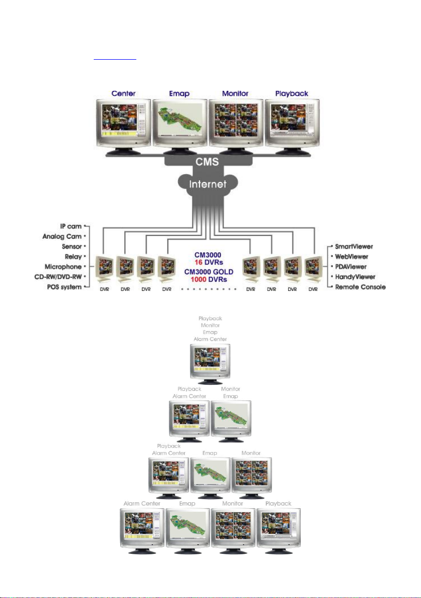
The AVerTM CM3000 is a central monitoring system that enables user to monitor up to 1000 DVR
servers (see also Chapter 1.1 for updating to Gold version) through an internet connection. Like the
DVR program, the CMS system also automatically records and displays video when an event has
occurred on the remote side of the DVR server. You can also playback video files locally or download
from a remote DVR server.
The CMS system Supports Single, Dual, Triple and Four monitor displays. User can operate the CMS
system application on different monitors.
1
Page 9

1 ~ 64 Clients(DVR)
65 ~ 150 Clients(DVR)
151 ~ 1000 Clients(DVR)
i
Without install a USB dongle, CMS only can monitor 16 DVR and some functions are not
available.
1.1 Upgrading to CMS GOLD Version
The CMS can be upgraded by installing a USB software License (USB Dongle). After installed the
USB dongle, CMS can monitor up to 1000 remote DVR servers. The USB dongle provides three type
of license for customer choice:
Please follow the below steps to upgrade the CMS.
1. Run the CMS application.
2. Plug in USB Dongle to your CMS server.
3. The CMS system will detect it automatically and the driver installation dialog will pop up. Click OK
to install the driver.
4. If user chooses to install driver later, then un-plug the USB dongle and plug in again later for
installing.
5. After installation completed, the CMS system will restart automatically.
6. DO NOT un-plug the USB Dongle while the DVR application is operating, it may cause the
application crash abnormally.
2
Page 10
1.2 Dual Monitors setting
Video configuration is different for each different VGA chipsets. Please follow the steps below to setup
the dual monitors display.
The CMS application supports resolution in 1280 x 800、1024 x 768、1280 x 1024、1440 x 900、
1680 x 1050、1920 x 1080 and 1920 x 1200.
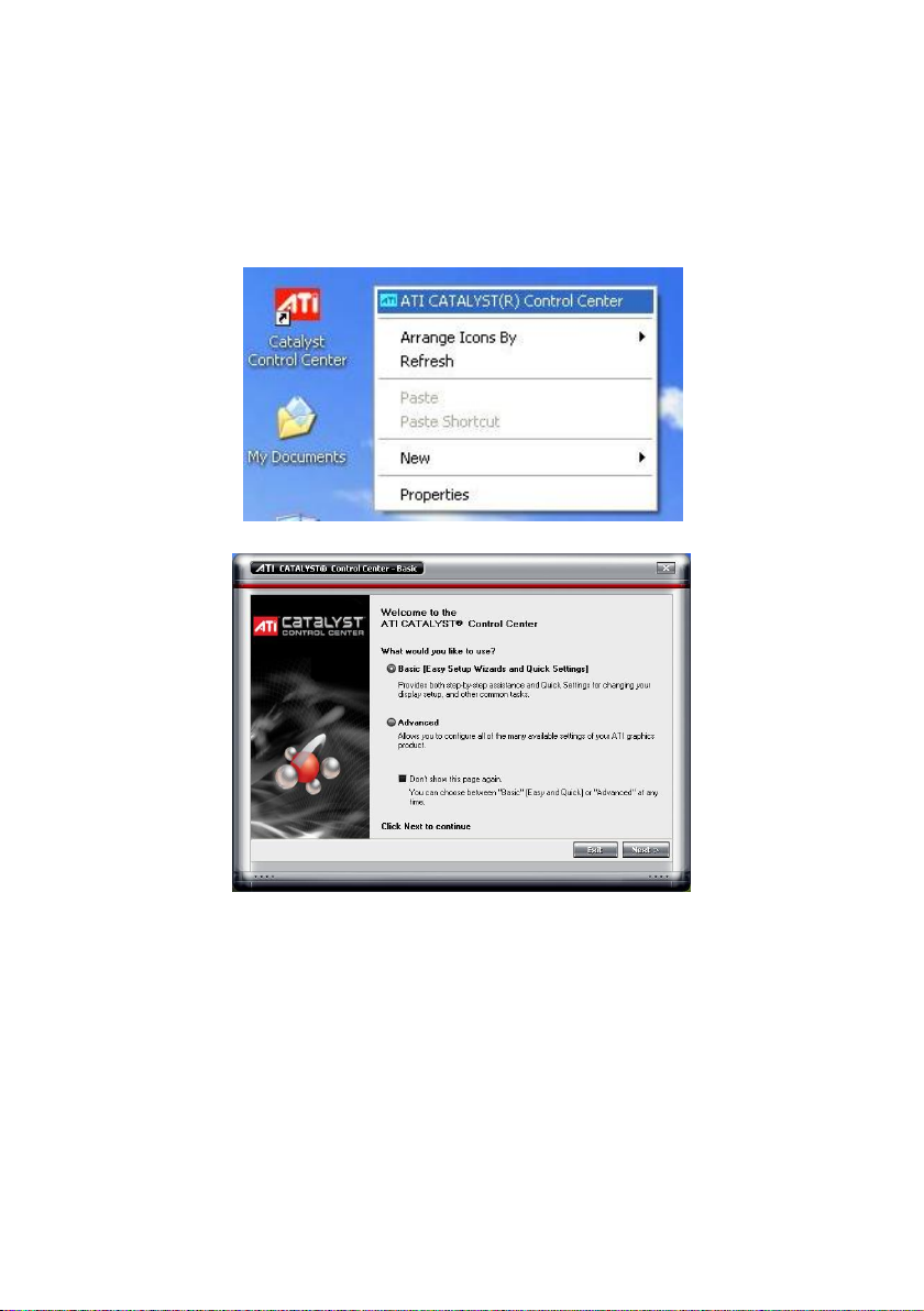
1.2.1 Graphic card with ATi chipset
1. Enter the ATI Catalyst Control Center, user can click the short-cut or right click on the screen.
2. There are two modes to select ─ Basic and Advanced.
3
Page 11
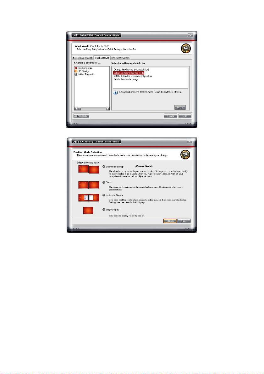
3. If user selected Basic mode, press the Quick Settings tab. Then select the Select a different
desktop mode and click Go.
4. Select the Extended Desktop and then click Finish.
4
Page 12
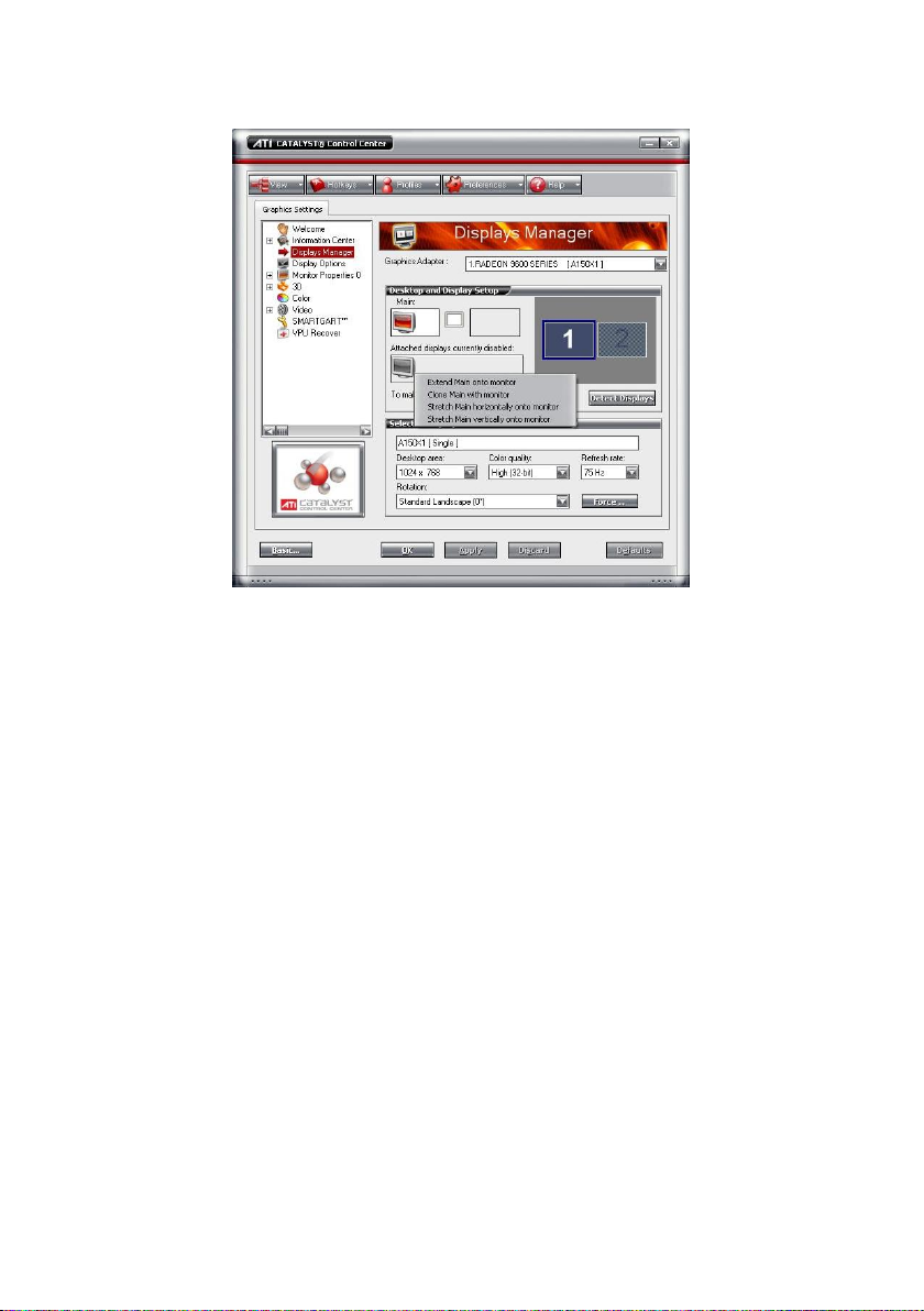
5. If user selected the Advanced mode, click the View button.
6. In Display Manager, right click on the second Display on the right side and select Extend Main
onto monitor.
7. Adjust each monitor resolution to 1280 x 800、1024 x 768、1280 x 1024、1440 x 900、1680 x
1050、1920 x 1080 or 1920 x 1200.
5
Page 13
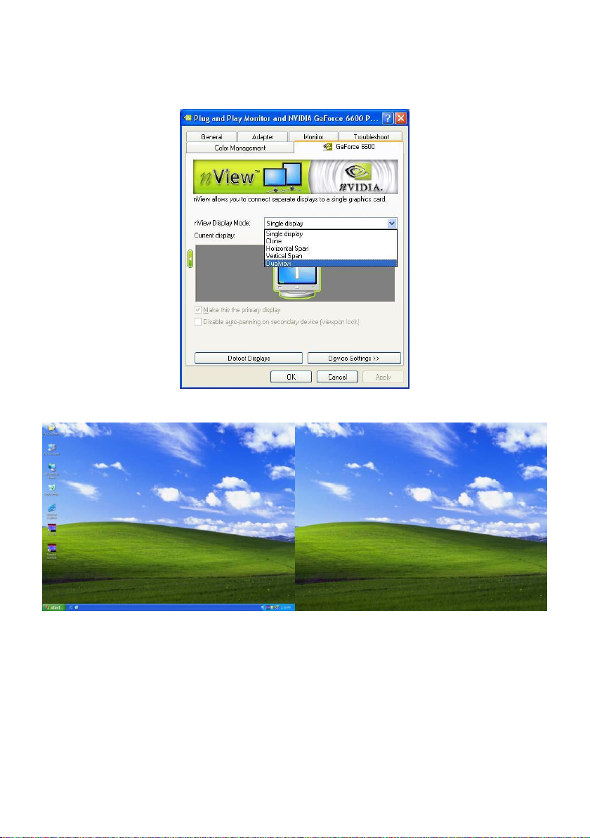
1.2.2 Graphic card with NVIDIA chipset
1. Click the NVIDIA nView, and select the Dualview mode.
2. Adjust each monitor resolution to 1280 x 800、1024 x 768、1280 x 1024、1440 x 900、1680 x
1050、1920 x 1080 or 1920 x 1200.
3. To review if the display mode is correct, you can check the task bar. The task bar will show on the
first monitor only.
Monitor 1 Monitor 2
6
Page 14
- Before installing the software, make sure the Windows OS patches are up to date and
the video graphic card driver is up to date.
- Please disable the User Account Control (UAC) function before install the CMPC
program. To disable UAC, please go to Control Panel >> User Account Control.
After disable UAC function, please restart system, and then, install CMPC
program.
i
To ensure you have the latest copy of the CM3000 software, download the updated version
from the following site:
Worldwide :
http://surveillance.aver.com/download-center >> Software Application >> CM3000 >>
Software; Click Search button
CPU
Pentium 4 3.0GHz or above recommended
OS
Windows XP Professional 32 bit/ 7 32bit & 64bit
RAM
512MB for dual display,1GB for Quad display
Hard disk
120GB or higher
Media
CD-ROM drive
VGA
32-bit high color SVGA graphics card with 256MB video memory and
DirectDraw / YUV Rendering Capability
Audio
Sound card and speakers
Internet capacity
10/100 Base-T Ethernet card or Gigabit Ethernet
Chapter 2 Software Installation
This chapter describes how to install the CM3000 software.
2.1 Minimum System Requirements
First, must verify if the computer meets the minimum system requirements.
7
Page 15
DO NOT install CMS application, NV DVR application, and MXR Client Software at the
same computer system.
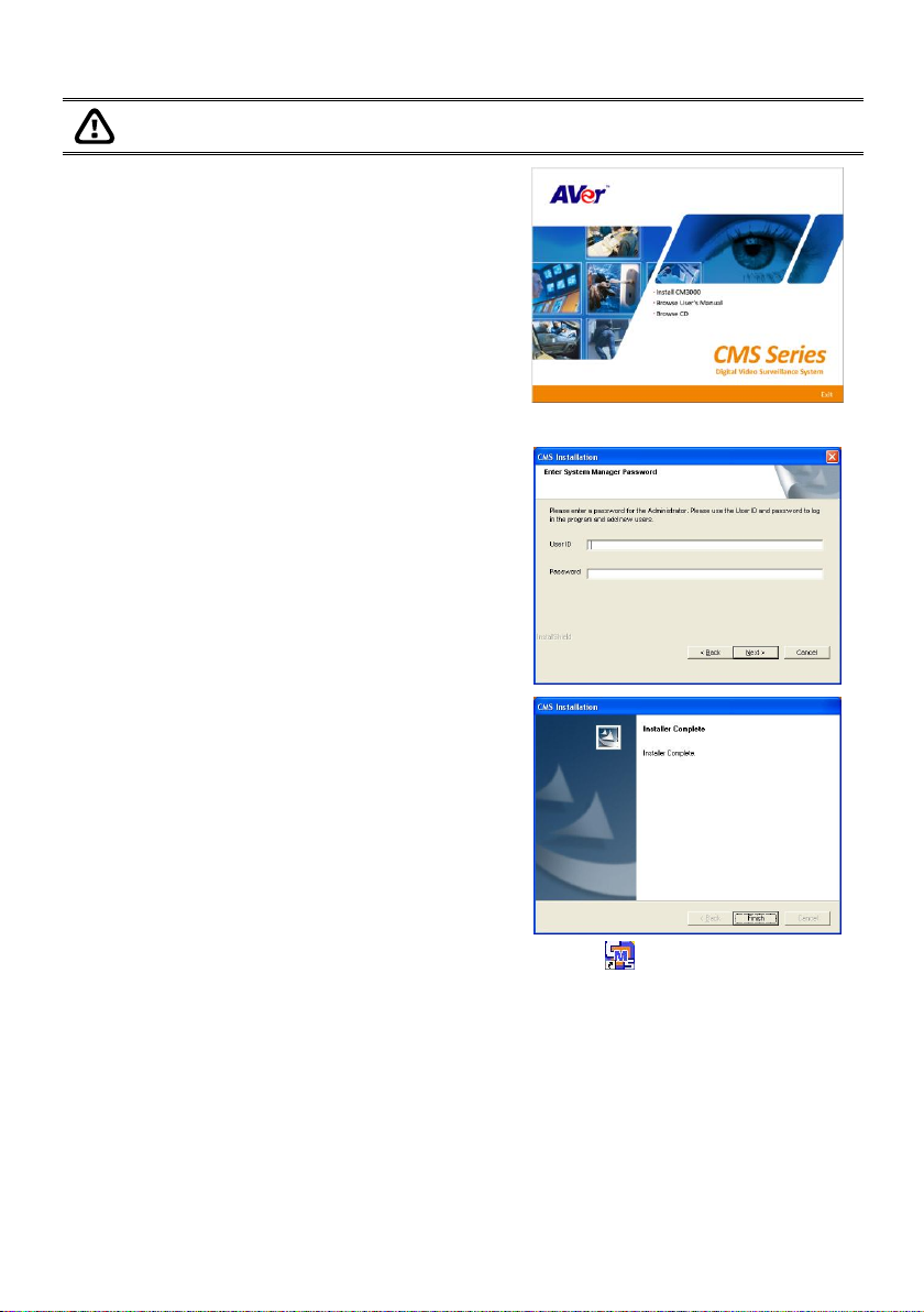
1. Place the installation CD into the CD-ROM drive
then click Install CM3000. And follow the onscreen instructions.
2. Please carefully read the license agreement. Click Yes to accept the agreement.
3. Enter the administrator ID and password.
4. Click Finish.
5. User may now run the CMS program. To run the application, click on your PC desktop or
click Start> >CMS > CMS >CM3000.
2.2 Installing the CM3000 Software in Windows XP/Vista/7
8
Page 16
Chapter 3 Using the CMS
3.1 Running the CMS Software
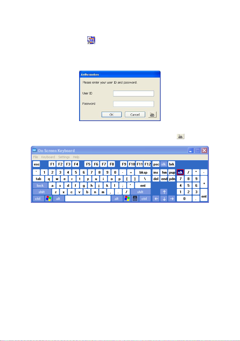
To run the application, double-click on your PC desktop or click Start > CMS > CM3000.
For security purposes, some of the features would require you to enter a User ID and Password before
they can be accessed. When the Authorization dialog box appears, key in your User ID and Password.
(If this is the first time, enter the one you have registered when installing the software.)
3.1.1 Using the Virtual Keyboard
If the keyboard is not available, you may use the Virtual Keyboard. Just click to show the virtual
keyboard. For uppercase and lowercase, click shift button.
9
Page 17
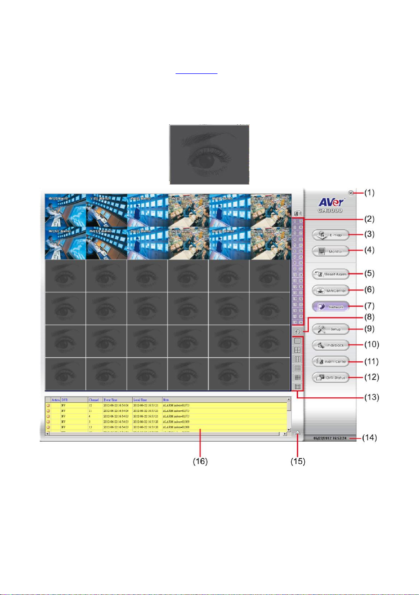
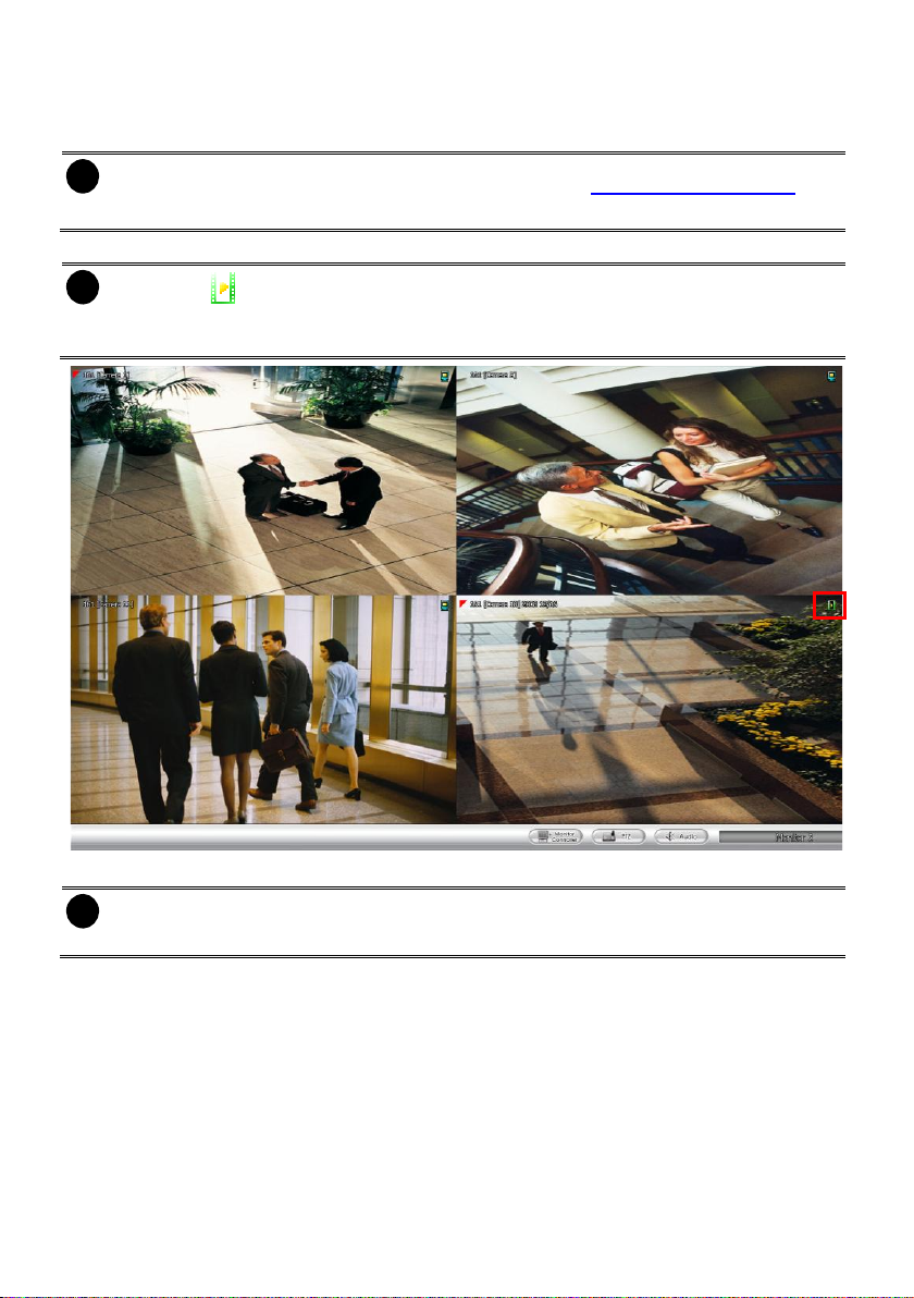
3.2 Using the CMS Application
When an alarm occurred on the DVR server, the video is transmitted to the CMS and display on the
main screen. The transmit video can be an image or live video. User can select the type of video
transmitting in System setting (see also Chapter 4.1). You may download and playback the complete
video directly from the DVR server by clicking on the event log. Make sure the main DVR server is
set to send video to the CMS when an alarm has occurred.
The video stream before the eye indicates the latest occurrence. Also, there is a red frame which
indicates the latest occurrence when the video transmitting is alarm image type.
CMS Center in Alarm Live Video Mode
10
Page 18

Name
Function
(1) Exit
Call up the Logout dialog box.
In the logout dialog box, you may do the following:
- Click Exit to close the CMS program. Only the administrator is
authorized to access this command.
- Click Login to sign-in as a different user.
- Click Minimize to reduce the CMS to taskbar button. The authorization is
required, please enter the password.
- Click Cancel to close the Logout dialog box.
- Click About to find out more about the software and update CMS
firmware.
Click Update in Product Information window to upgrade the newest CMS
application. In Live Update window, select the Server Site and Address
and click Update.
(2) Camera ID
Show the number of cameras that are being viewed. When you are in
single screen mode, click the camera ID number to switch and view the
camera. This function only available in Alarm Live Video mode.
(3) E-map (F3)
Switch to display the map and show the location of the DVR server on
the map. If you are using a single monitor, press ESC to revert back to
the CMS main application( see also Chapter 4.6.2)
(4) Monitor (F4)
Switch to display live video from the selected DVR servers group. If user
is using a single monitor, press ESC to revert back to the CMS main
application(see also Chapter 3.3).
(5) Reset Alarm
Click to reset all DVR alarm status
(6) MiniCenter Viewer
To call out the MiniCenter viewer. Also, user can double click on screen
or alarm event to call out the MiniCenter Viewer.(Also refer to Chapter
3.4 )
(7) Network
Enable/disable the remote alarm data received. This is activated
automatically when the CMS software starts up.
(8) Refresh
To refresh the alarm video that display on the screen. This function only
available in Alarm Live Video mode.
(9) Setup
Configure the CMS system settings. Only the administrator is authorized
to access this command. (see also Chapter 4)
(10) Playback
Select to playback video from the local hard disk or remote DVR server
(see also Chapter 5).
(11) Alarm Center
To view, search, and navigate the alarm (see also Chapter 3.5).
11
Page 19
Name
Function
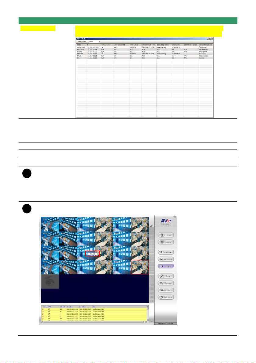
(12) DVR Status
To view all monitor DVRs’ status – IP, CPU usage, Bandwidth usage,
HDD free space, Connection status, Video Loss status….and so on.
(13) Split Screen
Mode
Select from 6 different split screen types to view all the cameras. It also
allows you to switch and view different camera number by click Camera
ID in a single screen mode. This function only available in Alarm Live
Video mode.
(14) Status
Display the current date, and time
(15) Log extender
Expand and reduce the log viewer
(16) Log viewer
List the entire info in event mode or text mode from all DVR servers.
i
There are a few Hot keys for quick switching between the different applications or display
mode on a single monitor system.
- F1: displays current DVR server information on the CMS Monitor screen
- F3: Switches to E-Map mode
- F4: Switches to Monitor mode
- Esc: Switches back to the CMS application main screen
i
When CMS Center in Alarm Image mode, right-click on the alarm image will call out Clear
All short-cut. Select to clear all current displayed alarm images.
CMS Center in Alarm Image mode
12
Page 20
i
Right-click on the channel screen could select to start recording.
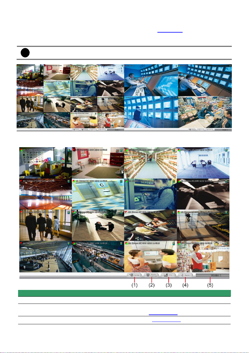
Name
Function
(1) Center
Back to CM3000 main UI(center UI)
(2) Monitor
Controller
To call out monitor controller dialog box. User can manage the monitor set
in monitor controller dialog( see also Chapter 3.3.1)
(3) PTZ
To call out PTZ control panel(see also Chapter 3.3.2)
3.3 Using the Monitor
When user has setup the monitor set in Camera Setup (see also Chapter 4.3), then click Monitor to
view all selected cameras live video and playback. The monitor will switch to monitor mode, if user
using more than one monitor, then all enabled monitors will switch to monitor mode.
Dual Monitor Screen
The following will describe the buttons function on Monitor interface.
13
Page 21
Name
Function
(4) Audio
Enable/disable audio. When audio is enabled, user will see the audio icon
on screen, click on the audio icon (audio icon will turn to green ) of
channel to hear the sound. Each time only can play one channel’s audio.
(5) Monitor Name
Display name of current monitor set.
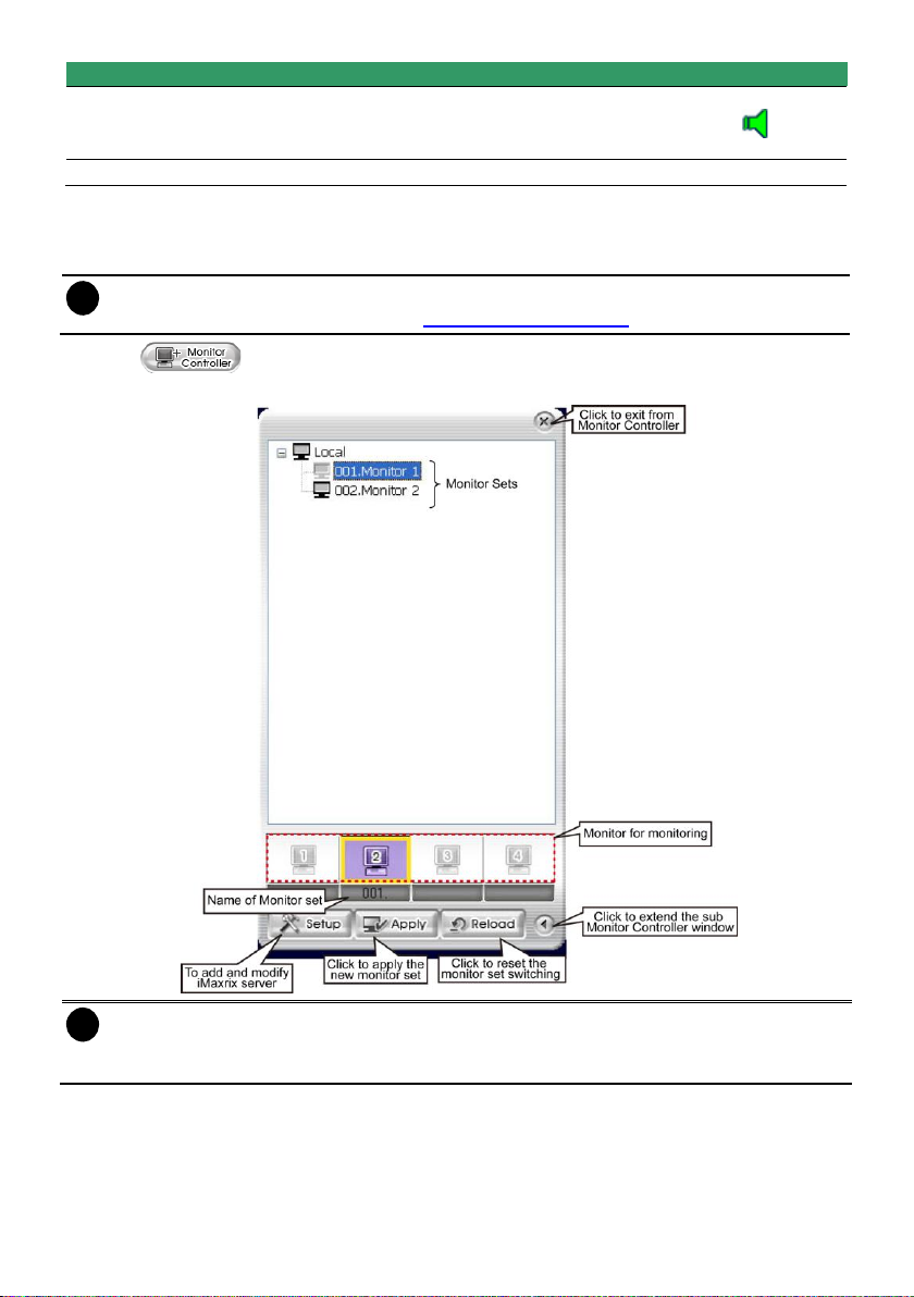
i
User needs to create monitor set in order to using Monitor Controller. To create monitor set,
please go to Setup > Camera (see also Chapter 4.3 Camera setup)
i
- The monitor set is gray that indicates the monitor set is selected and been monitored.
- The monitor 1 ~ 4 are purple that indicate the monitor is monitoring.
- Right-click on monitor and select the Recover to reset the monitor.
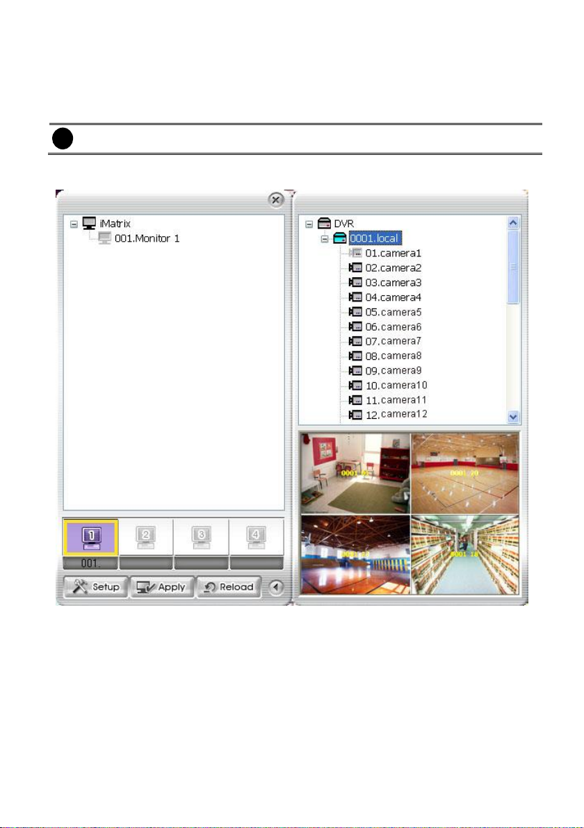
3.3.1 Using the Monitor Controller
User can use Monitor Controller to switch different monitor set for monitoring and add/delete the
channel in monitor set.
1. Click
2. The Monitor Controller window will show up as below shown:
3. Drag the monitor set from monitor list to the monitor (1 ~ 4) and click Apply to activate it. To reset
the monitoring group, click Reload.
4. To configure monitor set, click arrow button to expand the sub Monitor Controller window.
5. Select the monitor. The DVR servers are included in the monitor set will list on sub Monitor
Controller window. The lower part of window display all monitored channels in the monitor set.
14
Page 22
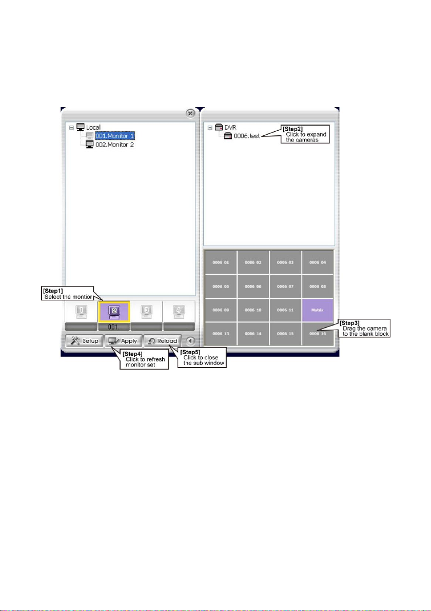
6. To add new channels, click the DVR server to un-fold the available cameras. Drag the camera to
the blank channel block that has no channel number and name display
7. To change the monitored channels’ position, please delete the monitored channels and drag the
channels to the new position. To delete channels from monitor set, right-click on channel and
select Recover.
8. Click Apply to refresh the monitor set.
9. Click arrow button to close the sub window.
15
Page 23
i
The remote iMatrix server only can be viewed and modified channel of monitor, add /delete
channel of monitor is not allowed.
i
Only can select one iMatrix server at a time.
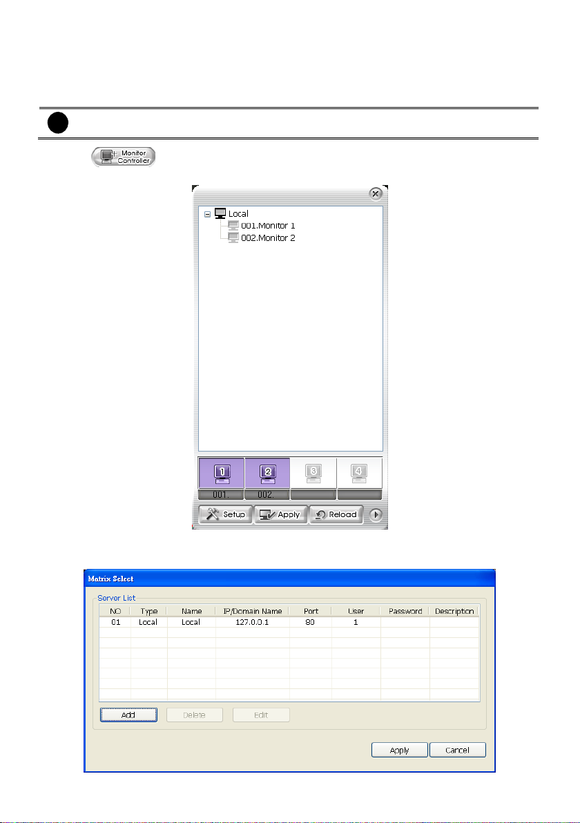
To Add the Remote iMatrix Server
User can add more remote iMatrix Servers and modify the monitored channel of the iMatrix servers
from remote site. iMatrix servers can be removed and modified by clicking Delete and Edit button.
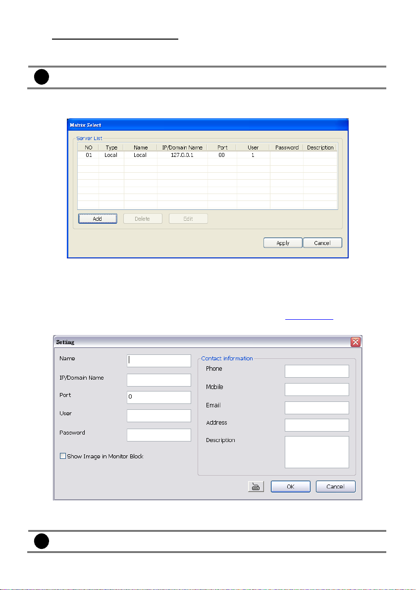
1. Click Setup from Monitor Controller dialog box.
2. The Matrix Select window will show up.
3. Click Add button to add a remote iMatrix server.
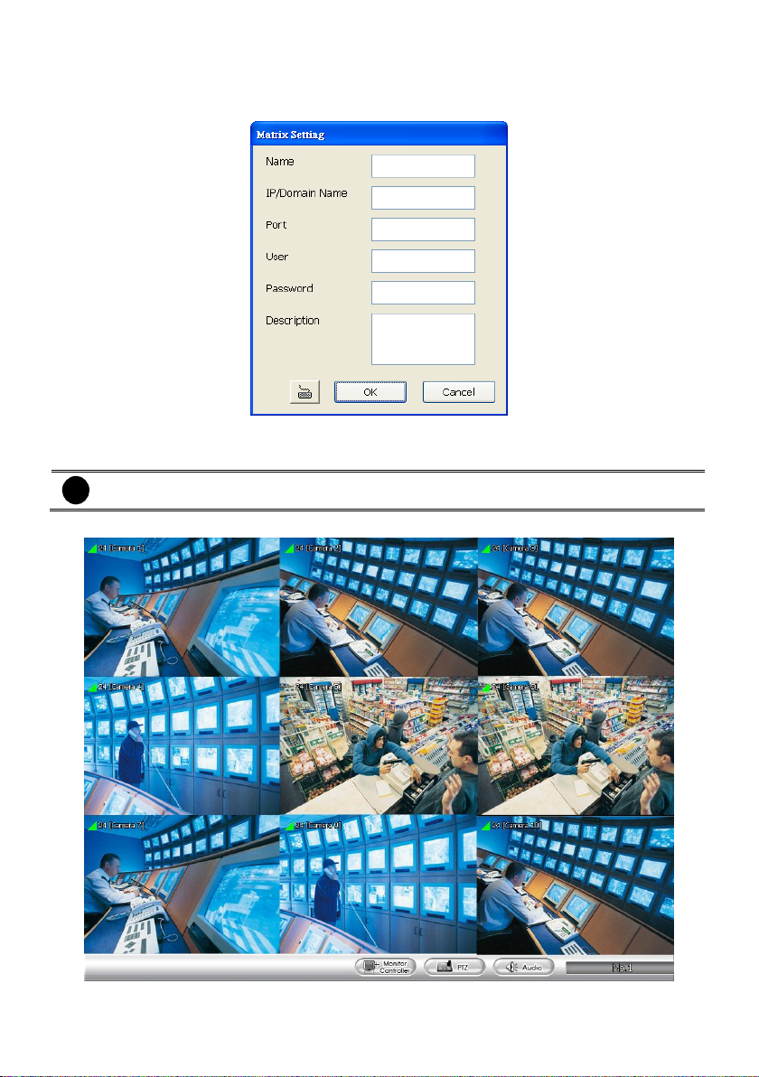
4. Fill in the Name, IP/Domain Name, Port, User (login ID), Password and Description of the
remote iMatrix server. Enter the Contact Information (Phone, Mobile, Email, Address,
Description) for emergency contact. Mark Show Image in Montor block if user wants to view
the image of the channel at the Monitor Controller window(see also Chapter 3.3.1)
5. And then, click OK to save the setting.
6. The iMatrix will be added into the iMatrix list in iMatrix Select window.
7. To switch the iMatrix server, select the iMatrix server and click Apply.
16
Page 24
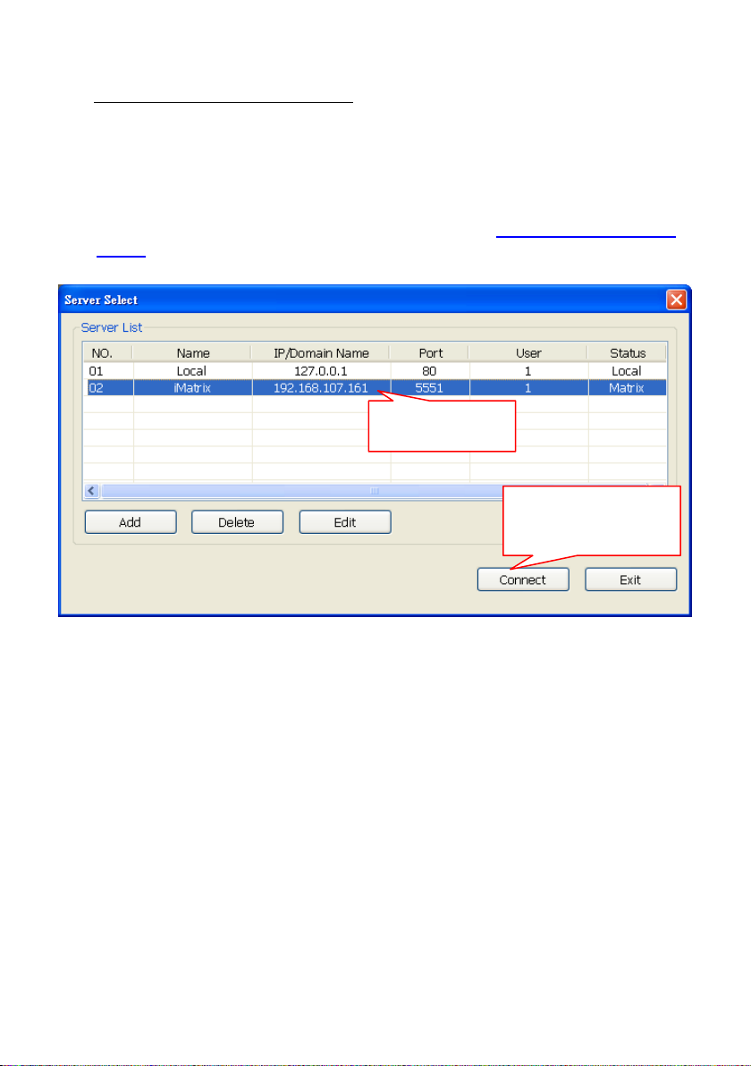
Click to select the
remote iMatrix server.
After selected the iMatrix
server, click Connect to
make a connection
8. To delete the iMatrix server, select the iMatrix server and click Delete. To modify, click Edit.
To Mondify the Remote iMartix Server
User can modify the monitored channels on Monitor Controller window. Also, the modification can be
applied to the remote iMatrix server.
【Step 1】Select the remote iMatrix server.
1. Click Setup button to call out Server Select window on Monitor Controller window.
2. Select the remote iMaxtrix server from Server Select window. If remote iMaxtrix server hasn’t
been added, click Add to add a remote iMatrix server(see also To Add the Remote iMatrix
Server)
3. After selected the remote iMatrix server, click Connect to make a connection.
17
Page 25
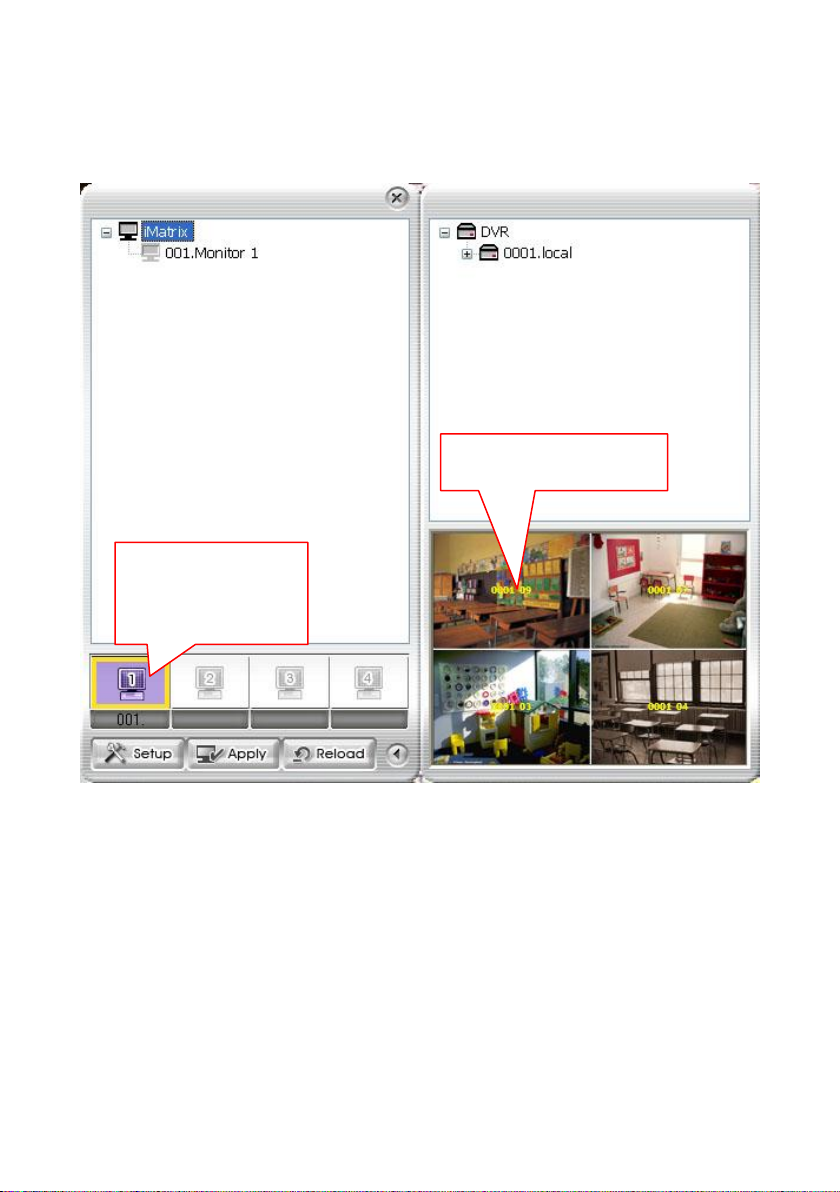
Double-click to get the
video image of monitored
channel form remote
iMatrix server.
The yellow text represents the
number of server and channel.
【Step 2】To get the video image of monitored channel from remote iMatrix server
1. Double-click the monitor icon to get the video image of monitored channel from remote iMatrix
server.
2. User will see the video image of monitored channel display on lower part of the sub-Monitor
Controller window.
18
Page 26
i
The camera icon in gray indicates the camera has been selected and monitored.
【Step 3】To modify the monitored channel of the remote iMatrix server
1. Click on the + of the DVR server icon to extend the list of channels on sub-Monitor Controller
window.
2. Drag the channel wants to monitor to the channel that located on lower part of sub-Monitor
Controller window. The channel will be switched.
3. Click Apply to update the modification to the remote iMatrix server.
4. User can go to iMatrix server to check that the monitored channel will change right away.
19
Page 27
i
The remote CMS server only can be viewed. To add and delete camera of monitor set is
not allowed.
3.3.1.1 To Monitor CMS Server from iMatrix Server
The iMartix server can connect to CMS and remote monitor CMS.
User can add remote CMS servers to monitor. The added remote CMS server can be deleted and
modified by click Delete and Edit button in Matrix Select window.
1. Click from iMatrix main UI.
2. The Monitor Controller window will show up as below shown:
3. Click Setup from Monitor Controller dialog box.
4. The iMatrix Select window will show up.
20
Page 28
i
Only can select one CMS server at a time.
5. Click Add button to add a CMS server.
6. Fill in the Name, IP/Domain Name, Port, User (login ID), Password and Description of the
remote CMS server. And then, click OK to save the setting.
7. The CMS server will be added into the iMatrix list in iMatrix Select window.
8. To switch to the CMS server, select the iMatrix server and click Apply.
9. The monitor screen will display the selected remote CMS server screen view.
Monitor UI of iMatrix Server
21
Page 29
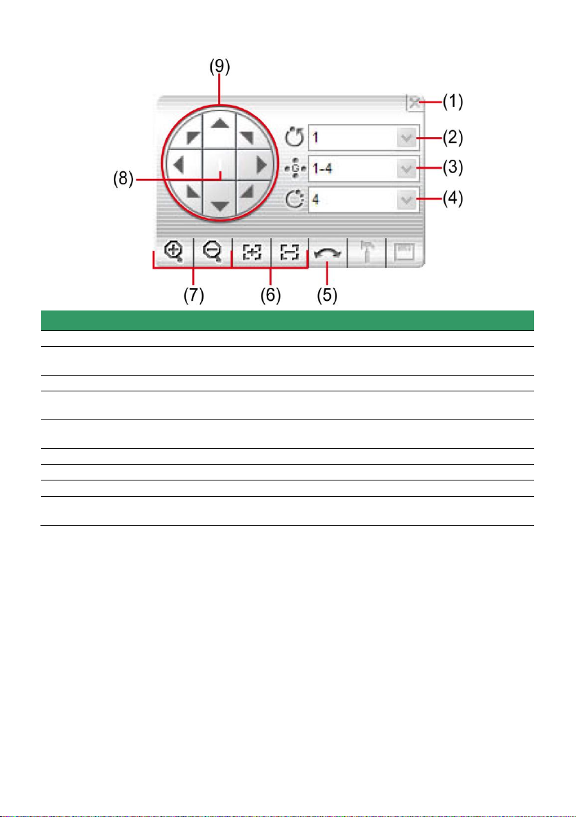
Name
Function
(1) Close
Exit PTZ camera controller.
(2) Camera preset
position number
Move the PTZ camera to the preset point.
(3) Group AutoPan
Select to automatically operate PTZ camera in group.
(4) Direction buttons’
moving speed
Adjust the moving speed of the PTZ camera lens. This speed will apply
to the (11) Direction buttons’ moving speed only.
(5) AutoPan
Operate the PTZ cameras automatically based on the selected camera
group preset position number.
(6) Zoom +/-
Zoom in and out the image.
(7) Focus +/-
Adjust the focus manually to produce clear image.
(8) Camera ID
Display the PTZ camera number that is being operated.
(9) Direction buttons
Move and position the focal point of the PTZ camera. The support of
direction button depends on the PTZ camera.
3.3.2 Familiarizing the Buttons in PTZ Camera Control Panel
22
Page 30
i
-
Playback function must be enabled. Please go to Setup > Camera and select the
monitor set and enable the playback function ( see also Chapter 4.3 Camera setup)
-
Playback doesn’t support on EB series.
i
- The icon indicates the channel is in live playback mode.
- Move the mouse course to the bottom of screen, live playback control bar will show
up.
i
- Click channel to switch to full screen mode for operating live playback control button
easily.
- Only supports 4 channel live playback at the same time.
3.3.3 Live Playback the Recorded Video
User can playback recorded video immediately while monitoring from the local CMS server if the
recording is enabled.
1. In Monitor mode, click the preview icon of channel and the channel will start live playback.
2. User can use the live playback control button to operate the playback.
23
Page 31

Button
Function
Begin: Move at the beginning of video.
Slower: Play the recorded video file at the speed of 1/2X, 1/4X, 1/8X,
1/16X, or 1/32X.
Pause: Briefly stop playing
Play: Play the video
Next: Go to the next frame.
Faster: Play the recorded video file at the speed of 2x, 4x, 8x, 16x or 32x.
End: Go to the end of the video.
Select recorded vide to playback from remote DVR server hard disk. Select
the date on the calendar and the time from 00 to 23 to where to start playing
the recorded video file.
24
Page 32

Button
Function
Display playback speed and recoding time.
i
Please make sure the software license version you has purchased is supported GPS on
Google function.
3.3.4 Viewing the GPS Data on the Monitor
If user has monitored the MOB DVR server, user can view the GPS information on Monitor. Also, user
can view the location of MOB DVR server on the Google map.
Display the GPS Data on the Monitor:
Follow the below steps to display the GPS data on the Monitor.
1. Click Setup in Center interface.
2. Enter the password for authentication. When CMS configuration selection appears, click DVR.
3. In DVR window, select the MOB DVR server or add the MOB DVR server (see also Chapter
4.2.1).
4. After selected the MOB DVR server, click Edit. The DVR Setting window will appear.
25
Page 33

i
Position of the GPS data display relate to the setting of Monitor Text Setting in the
System setting.
5. Select the Video Quality to High, and then, mark the Show POS message to display the GPS
data on the Monitor.
6. Click OK to save and complete the change.
7. If the MOB DVR server hasn’t been added any channels for monitoring, please refer to Chapter
4.3 to add the channels for monitoring.
8. Click Monitor to switch to Monitor mode. User should see the GPS data display on Monitor UI as
following shown:
26
Page 34

Viewing the GPS Data on the Google Map:
Following the below steps to view the GPS data on the Google Map.
1. In the Monitor mode, right-click on the channel that is monitored from MOB DVR server.
2. The shortcut menu will appear. And then, select the Start GPS.
3. The Google Map View window will show up.
4. Click on Maximum button to enlarge the Google Map View window.
27
Page 35

Click to select different display
mode – Map, Hybrid, Satellite,
or terrain.
Click to view in different
split screen mode when
there is more than one
channel of the Google
map.
Listing all channels that
have been enabled the
Google Map.
Zoom in/out the
Google Map.
5. Click Setup to setup the setting of the Google Map View window.
- Dialog mode: the way of the display of the Google Map View window. When in Simple mode,
user can select the server from Select Server.
28
Page 36

To setup the setting
of the Google Map
View Window.
Simple Mode Full Mode
- Map Mode: the way of display the channel of the Google map. Mark All DVR in one map will
enable all channels display on one Google Map window.
6. To disable the Google Map view, click X.
29
Page 37

Name
Function
(1) Preview
View live video. User can cancel the connection by clicking Disconnect
button if the connecting time is too long.
(2) View Alarm Image
Playback the alarm video clip that is stored on the local hard disk.
(3) Remote Playback
Set the amount of time before and after the event to be retrieved from the
DVR server. Click OK to accept and play the retrieved video and Cancel
to void the request (see also Chapter 5.3)
3.4 Using the MiniCenter Viewer
In Minicenter, user could configure, backup, operate the remote DVR, reset alarm and change priority
of alarm, and setup the camera of remote DVR.
30
Page 38

Name
Function
(4) Alarm Info
Display alarm event information which it was defined on DVR server.
User can select priority of alarm event and enter some description in
Memo column, and then click Save button to save the setting.
(5) Remote Backup
Remote Backup is purely for backing up the *.dvr file from the remote
DVR sever(see also Chapter 3.4.1)
(6) Remote Setup
Change the remote DVR server settings(see also Chapter 3.4.2)
(7) Remote I/O
To view sensor and relay, also to turn on/off relay on remote DVR. Select
the relay and right click to turn on /off or trigger the relay.
(8) Remote Control
Connect to the remote DVR server and operate the application. Select
the DVR server from the Name drag down list and click the Remote
Control button. To use this feature, make sure the DVR remote server is
enabled. For more details on software usage, please refer to the DVR
user manual.
i
This feature works with NV series v 5.7 above only.
(9 ) Reset Alarm
Clear the DVR server alarm list.
(10) Voice Phone
Enable/disable 2-way audio function. This function allows the CMS and
DVR server to talk via the internet using a microphone. Make sure your
microphone and speakers work before using this function. If the DVR
server Talk to web-client setting is disabled, you will not be able to hear
from the other side
(11) PTZ Control
Control the PTZ camera (see also Chapter 3.3.2).
(12) DVR Info
Display the DVR information that user has select to preview. User can
switch to view different DVR or camera by drag down the Name or
camera list. Phone, Address, Mobile, Email, and Description information
were defined when set up the DVR server.
31
Page 39

3.4.1 Remote Backup
Remote Backup is purely for backing up the *.dvr file from the DVR sever. You can select between
Auto Backup and Manual Backup. Auto Backup continuously archives one hour of the recorded data at
a time, starting from the specified date. As for Manual Backup, it only archives the recorded data of
selected date.
Auto Backup:
1. Click Remote backup button from Minicenter UI.
2. The Remote backup window will show up and list all added DVR servers.
3. Make sure CMS is connecting to DVR servers. If lost the connection with DVR server, select the
DVR server and click Reconnect button.
4. Select the DVR server that user wants to backup by marking the Enable Backup check box. The
marked Enable Backup will change to ON status.
5. And then, the CMS will start to backup.
32
Page 40

Manual Backup:
1. Click Remote backup button from Minicenter UI.
2. Select the DVR server and click Modify button.
3. Select the Manual Backup at DVR setting dialog. And, user can change the backup direction by
clicking Browse button.
4. And the, click OK to save the setting.
5. The Backup Mode of DVR server will change to Manual.
33
Page 41

6. To execute manual backup, select the file first. Click File Select and select the files that user
wants to backup and click OK.
7. Then, click Start to backup.
Quick Backup: To backup the selected date, time period and channel immediately.
1. Click Remote backup button from Minicenter UI.
2. Select the DVR server and click Modify button. If the Stop button is displayed, click it change to
Start button.
3. In DVR Setting, select Quick Backup option.
4. Click Browse to set the storage path.
5. Click OK and the Quick Backup dialog box will appear.
34
Page 42

6. Click Add to select the date, start/end time, and channel that user wants to backup. After selecting,
click OK to confirm. User can add multiple backup time file by repeating this step.
7. In Quick Backup dialog box, user will see the selected time period for backup is listed. Click
Backup button to start backup.
35
Page 43

i
The remote setup contents will be varied that depends on the type of DVR (NV series, SA
series, NX series, EB series, EH series, or EXR series) is monitored.
(1)
(2)
(3)
(4)
(5)
(6)
(7)
(8)
(9)
(10)
(11)
3.4.2 Remote Setup
Remote Setup is configuring DVR server from remote site.
Click the Remote Setup button to call out the DVR server setup window.
The following setup contents are NV series. Some of functions may not support on NX series and EB
series.
3.4.2.1 System Setting
In the System Setting window, click Update to accept the new settings, click Exit to exit without saving,
and click Default to revert back to original factory setting.
(1) Delete recorded data after
If you want the system to automatically erase the data after a certain days, enable the Delete
recorded data after check box and enter the numbers of days in Days text box.
(2) Delete event and alarm log after
If you want the system to automatically erase the event and alarm log files after a certain days, enable
the Delete event and alarm log after check box and enter the numbers of days in Days text box.
(3) Video Standard
Change and select the proper video system according to your camera video system. If the video
system setting is wrong, the video would appear abnormal.
(4) Attention Please
Check the attentiveness of the person who is monitoring the system. You may set the number of times
the Attention dialog box to appear in a day in Times per day text box.
When this feature is enabled, the Attention dialog box would appear. The person who is monitoring
the system must enter the same number that appears from the left box at the right text box and then
click OK.
(5) AutoScan Period
Set the display time gap from 3 to 10 sec. before it switches to the next camera.
36
Page 44

i
Enable overlay doesn’t support on NV3000T and NV5000T card.
(6) Login
Enable the conditions in Login section you want the system to automatically carry out.
- Auto record when login
Automatically start video recording when the NV DVR is executed.
- Auto start Network when login
Automatically connect to network when the NV DVR is executed.
- Login to compact mode
Switch to compact mode directly when the NV DVR is executed.
- Silent Launch
Enable the DVR system minimizes on the system tray automatically right after start up.
- Guest Mode
Automatically log in Guest mode when the NV DVR is executed. In guest mode, the functions
are limited to preview and playback only.
(7) Miscellaneous
Enable the conditions in Miscellaneous section you want the system to perform.
- Desktop Lock
Block window OS hotkey: Deactivate the [Ctrl-Alt-Del] and [Windows] keyboard key
functions.
Block windows OS pop-up window: To block any pop-up window from windows system.
- Beep if no signal
Make sound when the video signal is lost.
- Mandatory Record
Always record video when software is running
- Enable Overlay
To enhance video signal for better video quality.
- Screen Saver
Set a period time to enter screen saver mode when system idle.
- Auto Scan Period
Set the time gap of the Auto Scan function from 3 to 10 seconds. This automatically switches to
the next video in cycle depending on the set time gap.
- Playback Mode
Select the mode of playback the video.
Select date and time: Select the date and time which user wants to playback.
Play the last file: Automatically playback the video from the last hour
Instant Playback: Automatically playback the video which has just recorded
- Date Format
Select the date format which wants to display in Select date and time playback mode
37
Page 45

(8) Dual Monitor
To enable/disable dual monitor function.
(9) POS
Set from which camera screen to display the data from the POS equipment. Click Setting to enter the
setup window.
Advanced Setting
To setup POS text display position, text font
and color.
1. In the System Setting dialog box, POS
section, click Setting >> Advanced
Setting
2. Mark Show POS Text to allow POS data
to be display on surveillance screen.
3. Select the POS data display position on
surveillance screen – Left-Top, Left-Bottom,
Right-Top, or Right-Bottom.
4. Mark Multiple Windows to allow more
than one iPOS live data window display on
the preview screen mode.
5. Mark Save Window Position that iPOS
live data window position will be saved as next time call out position when close
6. Select the Cameras of iPOS live data that want to be display on Preview mode. To select all
cameras, mark All.
7. To change the POS data font and color, click Font.
38
Page 46

i
The UPS application must meet Windows XP or Windows 7 system requirements.
8. When it is done, click Save to complete the configuration.
POS Database Setting
Mark Remove POS data after the POS data will be delete from DVR hard disk on the day that
user has setup.
(10) UPS (Uninterruptible Power Supply)
Protect the system from damaging, such as power surges or brownouts. This automatically gives time
to close the NV DVR properly when the battery backup power has reached the Shutdown when
capacity below percentage level setting.
The UPS device must be connected to your computer (refer to your UPS user’s guide).
(11) System Information
Display current NVR system firmware version.
39
Page 47

i
Some of settings are not available to the IP camera.
(1)
(2)
(3)
(4)
(5)
(6)
(7)
(8)
i
Noise Reduction uses lots of CPU resource. Please use this feature only if it is really
necessary.
3.4.2.2 Camera Setting
Select the camera from remote DVR servers to modify settings. In the Camera Setting window, click
Update to save and apply the new settings, click Exit to exit without saving, and click Default1/
Default2 to revert back to original factory setting.
(1) Camera Icons
Select the camera number you want to adjust the video setting. To select all the cameras, enable the
ALL check box. To select more than one camera, Right click on the camera icon. To select one
camera only, Left click on the camera icon. The camera icon turns red when it is selected.
(2) Enable
Set to enable/disable the selected camera. When there is no video source on the camera, we suggest
disabling it so that the system won’t detect it as video loss error.
(3) Camera
- Display
Enable/disable to show the video. Even if the video of the selected camera is hidden you can
still record the video and preview it in playback mode.
- Name
Change the camera name.
- Description
Add a short comment.
(4) Video Adjustment
Adjust the Brightness, Contrast, Hue and Saturation of the selected camera.
(5) Noise Reduction
Reduce undesirable video signal and improve the quality of the video.
(6) Auto Brightness Control
40
Page 48

Automatically adjust the brightness.
(7) Night View
Automatically adjust the exposure to make the image more visible especially when the site is dark. You
can only use this function when the Auto Brightness Control is enabled.
(8) Enable Deinterlace
To enhance the video quality. Set the deinterlace mode to #1, if you are capturing motionless picture
and #2, if it captures lots of movement.
41
Page 49

i
Some of settings are not available to the IP camera.
(1)
(2)
(3)
(4)
(5)
(6)
(7)
(8)
(11)
(12)
(10)(9)
3.4.2.3 Record Setting
In the Recording setup window, click OK to accept the new settings, click Exit to exit without saving,
and click Default to revert back to original factory setting.
(1) Camera Icons
Select the camera number you want to set the recording setting. To select all the cameras, enable the
ALL check box. To select more than one camera, Right click on the camera icon. To select one
camera only, Left click on the camera icon. The camera icon turns red when it is selected.
(2) Recording Mode
The blocks from 00 to 23 represent the time in 24-hour clock. To record in full 24 hours, select the
recording mode and click the button. If you want to only record at a particular time, click the colored
block beside the recording mode then click on the time blocks. When the system starts recording a red
triangle mark would appear at the upper left corner of the screen. The recording modes are listed
below:
- Always Recording
Record the video from the selected camera and save it to the designated storage path
- Motion Recording
Start recording the video from the selected camera only when the system detects movement.
Once a motion is detected, the system automatically saves the previous frames and stop based
on the Start Record Prior and Stop Record After settings.
- Smart Recording
Automatically switch to recorded at the maximum frame rate setting once a motion is detected
and if there is no motion, it records at the minimum frame rate setting. Set the maximum and
minimum frame rate setting in (7) Frame Rate section.
- Vovice Detection Recording
DVR system will record when the voice exceeds the intensity value in Voice Detection setting.
- No Recording
42
Page 50

i
An Audio I/O card is required to use this function.
MPEG4
MPEG 4
Encryption
H264
H264
Encryption
MJPG
NV6120T
NV6240T
NV6480t
NV8416T
The system won’t do any recording.
(3) Audio
Select to assign the audio channel of the selected camera. You can only assign one audio channel to
one camera source. This way you can record both audio and video.
(4) Motion Detection
Adjust the sensitivity of the motion detector. The higher the value, the finer the sensitivity is detected.
When it detects a motion, a green triangle mark would appear at the upper left corner of the screen.
(5) Video Detection
Adjust the intensity of the audio detector. The system detects sound when it exceeds the intensity
value.
(6) Quality
Adjust the video quality. The higher the value, the lower the compression level and uses more hard
disk space.
(7) Frame Rate
Set the maximum number of frames to be recorded during motion and motionless state. The frame
rate ranges from 1 to 30 for NTSC and 1 to 25 for PAL. The higher the frame rate, it uses more hard
disk space.
(8) Video Size
Select the size of the video and click the button. The higher the size, the larger the file it create.
(9) Mask/Shield Edit
Mask, mark an area on the screen to disregards the motion in the marked area and to only monitor
outside the marked area. In the Mask/Shield Edit section, activate the Enable Mask/Enable Shield
check box. Click and drag a frame on the screen to create Mask area.
(10) Compression Type
User can refer the table below to check the NV card supports what type of compression. H264 is the
latest and advanced video compression format that delivers better video quality and smaller file size
but this uses more CPU resource. Advanced MPEG4 and MJPEG, both provide a standard for color
picture compression rate. MPEG4 uses higher compression rate and smaller file size. While MJPEG
uses slightly lower compression rate and bigger file size.
43
Page 51

i
When NV7480 card has enabled one channel encryption, the all channels will be
encrypted.
Video Encryption
Enable/disable to encrypt the recorded video that way only the person who knows the password can
clearly view the video playback. The file size would become 10 to 30% more. Enabling the Video
Encryption check box, you will be prompted to enter the password and retype the password for
confirmation. Make sure not to forget the password for you would not be able to decrypt the video
without it.
The symbol would appear on the upper right corner of the encrypted video screen. You may see
the video during live recording.
44
Page 52

Enable Storage Optimization
Enable/disable to save more storage space. Click Detail button to select the type of storage
optimization.
Monochrome Mode: The video will record in black and white.
Noise Reduction: To do the noise reduction before compression.
Disable Video Enhancement: To shutdown video enhancement function.
User also can select the Default Mode High/Medium/Low. Click ? button to view default mode
definition.
(11) Group
Click to view the camera group that user has been setup in Camera setup .
(12) Camera
Click to view the camera live video on screen.
45
Page 53

(1)
(2)
(3)
(4)
(5)
(6)
(7)
(8)
(9)
3.4.2.4 Network Setting
In the Network Setting dialog box, click Update to accept the new settings, click Exit to exit without
saving, and click Default to revert back to original factory setting.
(1) Server Name
Assign a name for the DVR unit. Letters of the alphabet and numbers only.
(2) Transmitting Cameras
Select and click on the camera number in the Transmitting Camera section you want to make it
accessible via internet using WebCam, Remote Console, PDA Viewer and Hand Viewer (still image).
To select all the cameras, enable the ALL check box.
(3) Remote Control Server
Enable/disable remote control from remote application (ex. CMS). Enter the remote accessing port in
Port column.
(4) Network Video Configuration
Set up the video quality and frame rate for viewing and transmitting to the remote program. Scrolling
adjust bar to set the Quality level and FrameRate level.
(5) WebCam Port
Activate Enable Anonymous Login to remotely access the DVR server without the need of password.
The default of WebCam port is 80.
(6) Voice Phone
Voice Phone is a 2-Way Talk feature that allows the client and server to talk via internet using
microphone. Make sure both microphone and speakers work before using this feature. If the Talk to
Web-Client is disabled, the person in the DVR server side can only hear the voice from the client side
that is when the WebCam 2-Way Talk button is activated.. The default port of voice phone is 9999.
(7) Network Time Synchronization
Adjust the DVR system time same as network time server. Fill in the Time Server IP address or
domain name. Select Automatic Synchronize time to set automatic synchronize time on a daily basis.
(8) 3GPP
Enable 3GPP that allows user to use browser on the mobile phone to view recorded video. Just enter
46
Page 54

http://DVR Server IP/3GPP on the browser of mobile phone, and then, user will receive the recorded
video from DVR server. Fill the RTSP PORT for 3GPP connection. Select the video size for
transmitting to user’s browser on the mobile phone.
(9) Other Configuration
- Enable Original Security Protocol
Enable new version DVR system to accept remote software with former version. For example,
if user uses CMS version 7.1 and connect to NV DVR server with version 7.3, and then, user
has to enable this option to make it work. It is due to that DVR system has some new security
protocol in DVR with version 7.3 and newer version, and it’s not compatible with old remote
software.
- Enable White List
An access permit list for the remote accessing of DVR server. Enter the IP address and click
Add. Or, enter a range of IP address and click Add. To delete the IP from the list, select the IP
and click Delete button. To reset the input, click Clear button.
- Enable HandyViewer
Enable remote users to use a PDA or a mobile phone to access DVR server and select the
video size and quality.
47
Page 55

- Network Bandwidth Limit
By Channel: Set the network bandwidth by each channel.
All: Set the total network bandwidth consumption limit.
48
Page 56

3.4.2.5 Schedule Setting
Schedule to record, backup, enable network, reboot and disable alarm of all the cameras either weekly
or one time. The number from 00 to 23 represent the time in 24-hour clock. The left most column
display the days in a week.
To Set the Schedule Setting:
1. Select the date in the calendar. Use and buttons to shift the calendar to the left or right.
2. Select the condition you want to schedule in the drop down list.
- Record
Activate all the cameras to start video recording at the set time based on the Recording setting.
49
Page 57

i
Make sure the backup folder and storage folder are not on the same drive.
i
Make sure the Windows operating system is set NOT to require you to login user name
and password. This way the system will be able to run NV DVR program.
- Backup
Save another copy of all the data at the set time and specified backup path. NV DVR
automatically updates and only backup the data that are not yet included in the archive.
To assign backup path, click .
Mirror Backup: Save a copy of all the data at the set time and specified backup path.
Incremental Backup: Only backup the data that are not yet included in the archive from
last time.
- Network
Activate NV DVR remote system to access at the set time. After the appointed time, the
Network function will be disabled. If the Network function is already enabled, the Network
function will not be disabled when the appointed time has ended.
- Reboot
Restart the PC at the appointed time.
- Disable Alarm
Deactivate the alarm at the set time temporarily.
3. Specify to either schedule it weekly or one time. Click to make a selection.
4. Click on the blocks to set the schedule. Or click All to select all. To store the setting, click Save. To
remove the settings, click Clear.
5. To end Schedule Setting, click Update to exit and accept the setting and Exit to exit without
saving the setting.
50
Page 58

(1)
(2)
(3)
(4)
(5)
(6)
(7)
3.4.2.6 Alarm Setting
In the Alarm Setting dialog box, click Add to insert and set new alarm setting, click Delete to remove
the selected alarm setting, click OK to exit and save the setting, Cancel to exit without saving, and
Default to revert back to original factory setting.
To set the Alarm Setting:
1. Click Add to insert and set a new alarm setting. Click the items in the (7) Alarm Setting List, if
you want to modify the alarm setting.
2. In (1) Alarm Setting number/Name/Description, display the selected alarm setting number in the
list below. Enter alarm name and description.
3. In (2) Enable Time, the number from 00 to 23 represent the time in 24-hour clock. Select the time
and click the block you want to activate or deactivate the alarm function. When it is deactivated
the color of the block turns white.
4. In (3) Conditions, you can set “Trigger if any” to activate if it falls to one of the conditions or
“Trigger if all” to activate if it falls to all conditions.
- In Camera section, select and click on the camera number (01 to 16) in Motion Detected and
Video Loss to set the condition for the system to alarm.
- In Missing and Suspicious Object Detected, click the camera number (01 to 16) and select
the certain object on the screen (right click on camera number for detailed setting)), and when
the certain object is missing or doubtful, the system will alarm. In Scene Change, when the
camera has been moved, the system will alarm, too.
- In Voice Detection, click the camera number (01 to 16) to the system to alarm when detect the
abnormal voice.
5. In (4) Sensor, select and click on the sensor number (use and to select the sensor) to set the
condition for the system to alarm. If the sensor normal status is high, set the sensor condition to
low.
- Enable/disable the Abnormal Event check box, to set the condition of the event for system to
alarm.
System Reboot: when the DVR system reboot without abnormal condition, the system
51
Page 59

i
Temperature setting doesn’t support on NV3000T/5000 card.
will send out the alarm message.
Abnormal Reboot: when the DVR system reboot in irregular condition, the system will
send out the alarm message.
Recording is switched off: when the recording has been stopped, the system will send
out the alarm message.
Network is switched off: when the network connection of DVR system is lost, the system
will send out the alarm message.
Hard Disk failed: when the hard disk can’t work normally, the system will send out the
alarm message.
Temperature: set a temperature limited of system for system to alarm. When DVR system
temperature is over the temperature limited, the DVR system will send out the alarm.
VGA Temperature: set a VGA temperature limited for alarm. When VGA temperature is
over the limited that user has set, the DVR system will send out the alarm.
Illegal Entry: any objects move between selected regions which user has set up in
Object Counting section, the system will send out the alarm. Select the entry (object
moves from region 1 to 2 or from region 2 to 1) and camera for system alarm detection.
- Enable/disable the POS Keyword check box, to scan the data from the POS if it matches the
keyword).
- Enable/disable the Alarm Message check box, to active with external alarm message by your
own program. For the detail configuration, please contact the local reseller.
6. In (5) Alarm Reset, click the camera number (use and to select the alarm) to set the reset
condition of alarm. Once alarm is reset, all alarm action will stop at the moment. If the sensor
normal status is high, set the sensor condition to low.
7. In (6) Action, you may now set the alarm action for the system to perform when the alarm
condition is activated.
- Launch E-Map
Display mini Emap screen.
- TV Out
Switch to only display the video on TV from where the alarm is activated.
- Enlarge Camera View
Switch to only display video in Preview/Advanced mode from where the alarm is activated.
52
Page 60

i
Gmail is supported now.
i
If the alarm is not triggered by sensor, the system will depends on the setting of motion
detected, video loss, audio detect, and sensor in alarm setting to send the alarm image and
alarm message.
- Send E-mail
Send an electronic text message. To setup click Detail (see also To Setup Send E-mail).
- File Transmission via FTP
Upload file to remote computer thru FTP (File Transfer Protocol). To setup click Detail (see also
To Setup FTP).
- Start Recording
Record the video from the selected camera. To setup click Detail (see also To Setup Alarm
Recording).
- Alarm SOP (Standard Operation Procedure)
List the instructions to inform the person of what to do when the alarm is activated. To setup
click Detail (see also To Setup Alarm SOP).
- Send to CMS (Central Management System)
Enable/disable the selected camera to send video to CMS when the alarm is activated (see
also To Setup CMS Setting)
To Setup Send E-mail Setting
Beside the Send Email check box, click Detail. In the E-mail Setting dialog box, click OK to exit
and save the setting and Cancel to exit without saving the setting.
- Mail Server
Enter the SMTP Server and port. If your e-mail system requires user identification, enable
Authentication check box and enter User ID and Password.
Mail
To check if it is working, click Test
Account button.
From: Enter the sender e-mail
address.
To and CC: Enter the recipient
email address and separate it
with comma or a semicolon (;).
Subject: Enter the message
title.
Message: Type the message.
- Email Notice Setting
Notice Interval: Set the period
of time before it sends another
e-mail notice.
Embedded image: Select the
sending image’s size and set
the number of frames.
Attach image when sensor is
triggered: When the sensor is
triggered, the system will
capture the image and send
the image to the certain e-mail
address with the alarm
message.
-
53
Page 61

i
- When camera is Analog or IP camera and recording resolution less or equal to D1,
the DVR system only record in key frame for pre-recording.
- When camera is Mega-pixel IP camera and the recording resolution is greater than
D1, the DVR system won’t do any pre-recording.
- Modem Dial up Setting
User may set the time to disconnect automatically, just enable the Auto Disconnect after
check box and set time.
To Setup FTP Setting
1. Beside the File Transmission via FTP
check box, click Detail.
2. In the FTP Setting dialog box, enter the
FTP IP, port, user ID and password.
3. In Number of Pic text box, enter the
number of sequence images that want to
send when file is transmitting. The
maximum number of picture can be
transmitted are 16.
4. If user wants to send the recorded image
before alarm occurs, enter the time that
before alarm occurs in Before
alarm(sec.).
5. Upload image: User needs to select the
camera that the images will be capture
and send when the any alarm is
triggered.
6. Click OK to exit and save the setting and
Cancel to exit without saving the setting.
To Setup Alarm Recording Setting
1. Beside the Start Recording check box,
click Detail.
2. In the Alarm Recording Setting dialog
box, select the camera to enable/disable
video recording. Enable All to select all
cameras.
3. In the Frame Rate selection, select As
Setting to record the number of frames
based on the Recording Setting or Max
to record the maximum of frames based
on the available speed.
4. In the Start Recording prior text box,
mark and set the number in second for
the program to pre-recording before the
alarm happen. The time range is 1~10
seconds.
5. In the Stop Recording after text box, mark and set the number in second for the program to
continue recording after the alarm has ended. The time range is 1~600 seconds. If user
doesn’t mark and set the time, the alarm recording will continue recording until alarm is reset.
6. Click OK to accept the new settings and Cancel to exit without saving.
54
Page 62

To Setup Alarm SOP
Beside the Alarm SOP check box, click Detail. In the
step text boxes, type the standard protocol when the
alarm is activated. When the alarm is activated, the
Standard Operation Procedure dialog box will appear.
Just click Next to see the next instruction, Back to see
the previous instruction, Finish to end and Abort to
terminate.
To Setup CMS Setting
Beside the Send to CMS check box, click
Detail. Click OK to accept the new settings
and Cancel to exit without saving.
CMS: Select the camera to
enable/disable sending the video to CMS.
Matrix: Select the camera to enable/disable
sending the alarm event video to CMS. The
CMS site need to setup a matrix channel to
receive the alarm event from DVR server
site(please refer to CMS manual for detail)
55
Page 63

i
Only CMS GOLD version supports full functions of Alarm Center.
3.5 Using the Alarm Center
User can manage live alarm event, searching the alarm event, and navigate relate parameters of
monitored DVRs, cameras, and alarm filters.
3.5.1 To Manage Live Alarm Event
User can select the alarm to assign to different operator, change the priority of alarm, and change
status of alarm.
1. Click Alarm Center.
2. Select Alarm Live tab.
3. Select the DVR or expand the alarm tree and select the alarm from left column of Alarm Live
window.
4. User should see all alarm events of selected the DVR or alarm.
5. To mark the alarm event, click check box.
6. Double-click on the alarm that user wants to manage. User should see the Alarm Information
Setting window show up.
56
Page 64

7. Click Edit Information to edit the alarm.
8. User can change Priority, State, and Operator of alarm. To enter the description or memo on
Note column. And then, click Save to save the change.
57
Page 65

i
The priority of alarm event is set on remote DVR server. User is allowed to customize the
priority of alarm event that CMS system has received and all re-assigned action will be
recorded on CMS system.
9. To exit, click Cancel.
10. Click Run Minicenter will call out Minicenter window(see also Chapter 3.4)
11. User can view alarm events by status or priority. Select the status or priority of alarm event from
the middle column of Alarm Live window and the result will be display on the right side column.
12. To manage the alarm event, follow the above steps 6 to 10.
58
Page 66

i
Alarm Search will be available when USB Dongle is installed (CMS GOLD version).
3.5.2 To Search the Alarm Event
User can search the alarm event by the conditions.
Set the follow conditions to search the wanted alarm events.
Server Name: select the DVR or select All.
Alarm Name: select the alarm that user wants to search for.
Type: select the alarm condition ( Motion, Alarm, DVR Exit, Login, Connection Loss, Connection
Success, Video Loss, HD Failed, and Reset Alarm)that user wants to search for.
Priority: select the priority level of alarm that user wants to search for.
59
Page 67

i
User also can create a filter in Navigation section(see also Chapter 3.5.3)
Status: select the alarm status that wants to search
Operator: select the operator that wants to search
Keyword: enter the specific word string to search.
After/Before Time: set a specific time period to search.
When the search conditions are set, click Search to start searching. If user doesn’t set any conditions,
the system still will start search when click Search button. And the, result will be all alarm events. The
search result will display on the right column of Alarm Search window.
User can select the alarm to assign to different operator, change the priority of alarm, and change
status of alarm (see also Chapter 3.5.1).
User can create a filter that is based on the conditions of search. Click Save, the Filter Window
Setting will show up. Enter a name for the filter and click OK.
60
Page 68

When receive the alarm, it
will turn to red and flash.
When CMS system receives same alarm event, filter will flash in red light. To minimize the filter
click , click to close the filter.
The result of search can be print by clicking Print button. Also, the search result can be save as in *.txt
and *.xls format by clicking Export .txt or Export .xls button.
61
Page 69

Clicking Image Log button to view alarm image. The image log window will show up. Double-click on
the image log will call out the MiniCenter window (see also Chapter 3.4). Click << and >> to go
previous and next page.
62
Page 70

i
Navigation function will be available when USB Dongle is installed (CMS GOLD version).
Click to call out
virtual keyboard if
the keyboard is not
available.
Image of the selected alarm
3.5.3 To Navigate the Alarm Information
User can view information of DVR, alarm, filter, and user.
Viewing the DVR Information
Select the DVR, alarm, filter or user to view. The information will be display on middle column and the
image of alarm will display on right side column.
To Create and Manage the Filters
The filter window display the current existing filter, user can add more filter by clicking Add. In Filter
Window Setting, enter the name of filter; select the DVR, alarm, and priority of alarm.
63
Page 71

Right-click on selected filter
will call out the shortcut
menu. User can Delete,
Edit, and Enable filter.
When CMS system receives
the alarm, it will turn to red
and flash.
The filter window in minimize status.
To delete the filter, select the filter and click Delete. To modify the filter, click Edit. Select the filter and
click Display filter can call out the filter to view if the filter is close.
Viewing the User Account
In User Configuration section, user can view who is current on line.
64
Page 72

Chapter 4 Customizing the CMS System
In the CMS application, click the button to customize the CMS system. In the Authorization
dialog box, enter the administrator User ID and Password.
When the CMS configuration setup selection appears, select and click the buttons you want to change
the setting.
4.1 System Setting
In the System Setting dialog box, click OK to accept and start to reload the new setting, and Cancel to
exit without saving.
65
Page 73

i
If CMS system is going to transmit the received alarm to Remote iAlarm center, please must
select the MySQL as the database.
(1) Alarm Network Port
Select a port for receiving alarm video from DVR server. Any network service port can be
assigned as long as the port doesn’t conflict with current network service.
(2) Database
Local: The default setting.
MySQL: If CMS server is sending the received alarm to the Remite iAlarm agent, please
select MySQL as the database. Please enter the communication Port of MySQL server and
the login Password.
Alarm Record Path
By default, the alarm folder is automatically generated to where the CMS application is installed
and for saving the alarm clip videos and log files. The suggested hard disk capacity for storing the
alarm video is 30GB.
1. Click Setup.
2. In the Authorization dialog box, enter the administrator User ID and Password.
3. Click System > . In the Browse For Folder dialog box, locate where you want to store
the alarm video clip. Click Make New Folder to create new folder, OK to accept and Cancel
to exit.
4. The text below the Alarm Record path text box shows the hard disk free space and total
space in parenthesis.
5. In the System Setting dialog box, click OK to start reloading the new setting and Cancel to
exit without saving the new setting.
(3) Miscellaneous
Date Format : Select from different date formats
1. Click Setup.
2. In the Authorization dialog box, enter the administrator User ID and Password.
3. Click System.
4. In the Date Format drop down list, click and select the style.
5. In the System Setting dialog box, click OK to accept the new setting and Cancel to exit
66
Page 74

i
The Model of System Controller must match on the System Controller site.
Display position: CMS system supports up to 4 monitors, users are allowed to customize
System Controller – To configure the parameters that is for communicating with the
without saving the new setting.
the display position that to decide the Center, Emap, Monitor, or Playback to be displayed on
which monitor screen. Click Detail to select the display screen setting. The new screen
display setting will be effect at next time login.
System Controller (an optional accessory). Also please refer to Chapter 4.1.1 or user
manual of the System Controller. Click Setting to configure system controller.
USB Connection: CMS can connect with System Controller through the USB port.
Follow the below description to enable the connection between CMS server and
System Controller.
Enable – Mark the check box to enable the System Controller function.
Model – Select System Controller Pro as the Model.
Upgrade – To update the firmware of the System Controller. Click Upgrade button
and click Select File button. And then, select the firmware file and click OK. The
upgrade process will start. The upgrade firmware may have more than one file.
Therefore, click OK and locate the firmware file to upgrade another file. When the
upgrade process is done, click Finish to complete.
67
Page 75

i
The Google map function only supported in CM3000 Gold version.
RS485 Connection: Connecting CMS with System Controller through RS485 port on
the System Controller. Follow the below description to enable the connection between
CMS server and System Controller.
Enable – Mark the check box to enable the System Controller function.
Model – Select System Controller Pro 485 as the Model.
Port – Select the com port that is connected with the System Controller.
Server ID – Set an ID for CMS server (0~99). This ID is a CMS server ID for
System Controller to select.
Google API Key: Enter the Google API Key that applied from Google web site (see also
Chapter 4.1.2). Click Detail and enter API key that will allow user to use Google map as a
E-Map image(see also Chapter 4.6.1.1).
Block Windows OS hotkey: Deactivate the [Ctrl-Alt-Del] and [Windows] keyboard key
functions.
Auto Login when OS start: Execute the CMS when the operating system is started.
(4) Attention Please
Check the attentiveness of the person who is monitoring the system. You may set the number of
times the Attention dialog box to appear in a day in Times per day text box. To check the graph
on how fast the person response, click Analysis. When this feature is enabled, the Attention
dialog box would appear. The person who is monitoring the system must enter the same number
that appears from the left box at the right text box and then click OK.
(5) Configuration
Import / Export the CMS system configuration.
68
Page 76

The camera information will be display as
user has configured.
User can press F1 to disable/enable camera
information display.
(6) Language
Customize the system to display the tool tips and dialogs based on the selected language. By
default the set language is in English.
1. Click Setup.
2. In the Authorization dialog box, enter the administrator User ID and Password.
3. Click System.
4. In the Language drop down list, click and select the language.
(7) Alarm Video
Set up the video transition when alarm occurs.
- One frame: a single video frame will be transmitted when alarm occurs.
- Pre/Post Event Time: Set the video duration before and after the event to send
(8) Show when receive DVR alarm
Select the type of received alarm format – Alarm image or Alarm Live Video.
- Alarm image: Only display alarm image and no live video previewing.
- Alarm Live Video: User can view alarm live video.
(9) Alarm Display
Select the alarm display on screen. User can select to display 4-split pop-up alarm display or one
full screen alarm display on screen. This is co-work with video pop-up function in Chapter 4.7
Alarm Setting.
(10) Monitor Text Setting
Enable/disable the camera information display and display position on the monitor screen. To
configure font, click .
69
Page 77

Function
Description
(1) USB Port
2 * USB ports for connection of keyboard, mouse, or USB flash memory.
(2) Audio Input
For audio input device connection such as microphone.
(3) Audio Output
For audio output device connection such as speaker.
i
- The audio input and output device has its own power supply is necessary.
- The audio input and output port act as the audio input and output port on the DVR
system.
Function
Description
(1) RS485 Port
To connect with CMS server, user needs a RS485 to RS232 converter (see
also Connecting the DVR Server through the RS485 port).
1
TX+ 2 TX- 3 RX+ 4 RX-
5
GND
(2) Power Supply
Port
For AC power adaptor connection.
4.1.1 Using the System Controller
The AVerTM System Controller Pro provides user an easy way to operate CMS server.
4.1.1.1 Hardware Introduction
Left Side
Rear Side
70
Page 78

Function
Description
(1) (Lock)
To lock panel buttons and all operations are lock. Press it to lock and press
again to un-lock. If the system password has been set, please enter the
password to un-lock (see also 4.1.19 Locking System Operation)
(2) (Power)
Lights up when unit is power on.
(3) Playback Control
Buttons
Press it to enable/disable the jog/shuttle function.
When button lights up is enabling.
(Pause)
To pause the playback.
(Play)
To switch to playback mode and start playback.
(Jog/Shuttle)
- Jog dial (top part): Playback video frame-by-
frame that control by user.
- Shuttle ring (lower part): Playback video at
faster forward or rewind speed that control by
user.
i
The Jog/Shuttle doesn’t support on Realtime Playback mode.
(4) LCD Screen
To operate the each function in multi-functions menu and view system
related information.
(5) Multi-function
Buttons
Each button represents a function that is corresponding to the function
display on the LCD screen. Press the button and operate it.
(6)
Enable/disable the PTZ camera move automatically that is based on the
selected camera group preset position number.
Familiarizing with System Controller Panel Buttons
71
Page 79

Function
Description
(7) Custom
Function Buttons
To view system information.
Back to the CMS center interface.
Call out the virtual keyboard.
i
The F3 function doesn’t support on Windows 7 64-bit system
platform.
Switch to monitor mode.
Call out the Mini Center.
Enable/disable network connection. Press it to connect the
network and press again to disconnect the network. The
authentication password is required for stop network
connection. Using numeric key pad to enter the password and
press Enter button to confirm.
To enter system setup mode. The authentication password is
required to enter system setup mode. Using numeric key pad
to enter the password and press Enter button to confirm.
Call out Logout dialog.
(8) Preset Button
Move the PTZ camera to the selected preset position.
(9)
Enable/disable joystick as a mouse function.
(10)
When lights up in green, user can use PTZ related operation.
(11) Joystick
To control PTZ camera to left, right, up, down, zoom in, and zoom out.
Press Cursor button to act as mouse function
(12) Focus Button
To adjust the focus of the PTZ camera.
(13)
Enable/disable digital zoom.
(14) Numeric Key
Pad
~
For numbers entering
Enter button
For confirmation
To delete the entered number
&
In LCD screen, moving the cursor to left or right.
72
Page 80

Function
Description
(15) Back /Top Menu
Button
Go back to previous LCD screen.
- Go back to the main menu screen.
- Exit from playback mode.
(16)
(Camera Select)
Using to select the camera channel in Monitor mode or Watch mode.
(17) Microphone
Build-in microphone for 2-way talk in Mini Center but user needs to press
button to enable the microphone function before using.
(18)
(Monitor Select)
Select a CMS server in 485 CMS mode (see also To Select a CMS server
ID in 485 CMS mode).
(19)
Switch to full screen mode in playback mode.
(20)
Press to enable built-in microphone function in Mini Center.
(21)
Switch to Emap mode (see also EMap Mode Operation section).
(22)
Take a quick screen shot of the surveillance screen and save it in playback
mode.
(23)
Switch to Center mode.
73
Page 81

4.1.1.2 Installation of System Controller
Connecting the CMS Server through the USB port
The following is an example of System controller installation.
1. The CMS server should be power on and CMS program is executed.
2. Plug the power cord of the System Controller into power outlet.
3. And then, plug the USB cable that is attached on the System Controller to the USB port of the
CMS server.
4. After CMS server and System Controller have well connected, user needs to do the configuration
for CMS server and System Controller to recognize each other. Please follow the below steps to
configure the CMS server and System Controller.
CMS Server site
a. Click Setup button on CMS program UI and select System.
b. In System setting window, click Setting button of the System Controller.
74
Page 82

c. In System Controller Setting window, Mark Enable check box to enable the System
Controller function. And then, select the System Controller Pro as the Model from
drop-down list. Click OK to complete the setting.
System Controller site
a. In main menu, press and select (system controller setting).
b. In System Controller setting screen, select .
75
Page 83

Current
System
Controller
Mode
c. In Mode screen, select the . If the current mode is USB-CMS mode already, then
the selection will not show in selection list.
d. Press button to confirm. To cancel the selection, press button. When the
“Complete” message appears on the LCD screen, the mode switch is completed.
5. After complete the mode setting in CMS server and System Controller, the System Controller is
ready to operate CMS server.
76
Page 84

RS232 cable
RS232 to RS485 Converter
(*User can purchase from the dealer
** The RS232 to RS485 Converter needs
to support RS-485 automatic data
direction control protocol)
Single core wire
Connecting the CMS Server through the RS485 port
Through the RS485 port, user can connect a CMS server with the System Controller.
Before starting to make a connection, please prepare the following items:
1. Using the screwdriver to press down the orange tenon and insert the single core wire cable into
the pin hole of the I/O terminal on the System Controller. When the wire cable is inserted in the
end of the pin hole, release the orange tenon to fix the wire cable.
2. Set the DIP switch of the RS232 to RS485 converter at 4-wire RS485 setting.
77
Page 85

RS485 pin hole of System Controller
RS485 to RS232 Converter site
System Controller site
R+
T+
1
R-
T-
2
T+
R+ 3 T-
R-
4
3. Using the screwdriver to lose the pin hole of RS485 to RS232 converter. And then, insert
another side of single core wire into the pin hole of the RS485 to RS232 converter. Using the
screwdriver to screw tight the wire. Please refer to the below table for pin-hole matching:
4. Connect the RS232 cable to the RS232 port of the converter.
5. Connect another side of RS232 cable to the RS232 port of the CMS server.
6. Power on the System Controller.
7. The following figure is an example of the installation illustrate.
78
Page 86

8. After CMS server and System Controller have well connected, user needs to do the
configuration for CMS server and System Controller to recognize each other. Please follow the
below steps to configure the CMS server and System Controller.
CMS Server site
a. Click Setup button on CMS program UI and select System.
b. In System setting window, click Setting button of the System Controller.
c. In System Controller Setting window, Mark Enable check box to enable the System
Controller functions. And then, select the System Controller Pro 485 as the Model
from drop-down list and select the Port that use to connect with System Controller.
Finally, set an ID for CMS server that is allowing System Controller to match to the CMS
server. Click OK to complete the setting.
System Controller site
1. In main menu, press and select (system controller setting).
79
Page 87

Current
System
Controller
Mode
2. In System Controller setting screen, select .
3. In Mode screen, select the . If the current mode is 485-CMS mode already, then
the selection will not show in selection list.
4. Press button to confirm. To cancel the selection, press button. When the
“Complete” message appears on the LCD screen, the mode switch is completed.
5. After mode setting has complete, user need to enter the ID of CMS server in order to
operate the CMS system.
6. Press button on System Controller panel. The LCD screen panel will display the
CMS ID select screen as following shown:
80
Page 88

7. Using the number keys on the System Controller panel to enter the DVR server ID that
user wants to control. And then, press the Enter button.
8. Now, the System Controller has switched the control to the CMS server that user has
selected.
81
Page 89

4.1.1.3 Operating the LCD Menu
Main Menu
On the LCD screen, each function is corresponding to the button on the panel of the System Controller
Pro. To select the function, press the correspond button.
Multi-Function Menu
In multi-function menu screen, press the correspond button of the selections to configure/operate.
To go back to the main menu, press the TOP MENU button. Press the BACK button will go back to the
previous screen.
82
Page 90

4.1.1.4 Familiarizing with LCD Screen
Following will describe the information or icon that display on LCD screen.
Main Menu
Submenu(Multi-function menu)
83
Page 91

i
- The default mode is USB CMS mode
- The 485 PTZ mode is not supported for CMS system.
- Please remember to setup the System Controller model as System Controller Pro in
CMS system.
Current System
Controller Mode
4.1.1.5 Switching to USB CMS Mode
When the System Controller is connecting with CMS server through the USB port, the System
Controller mode should be in USB CMS mode in order to operate the CMS system. If the mode is not
USB CMS, please follow the below steps to switch to USB CMS mode.
1. In main menu, press and select (system controller setting).
2. In System Controller setting screen, select .
3. In Mode screen, select the . If the current mode is USB-CMS mode already, then the
selection will not show in selection list.
4. Press button to confirm. To cancel the selection, press button. When the
“Complete” message appears on the LCD screen, the mode switch is completed.
84
Page 92

i
- The default mode is USB CMS mode
- The 485 PTZ mode is not supported for CMS server.
- Please remember to setup the System Controller model as System Controller Pro
485 in CMS system.
Current System
Controller Mode
4.1.1.6 Switching to 485 CMS Mode
When the System Controller is connecting with CMS server through the 485 port, the System
Controller mode should be in 485 CMS modes in order to operate the CMS system. If the mode is not
485 CMS mode, please follow the below steps to switch to 485 CMS mode.
1. In main menu, press and select (system controller setting).
2. In System Controller setting screen, select .
3. In Mode screen, select the . If the current mode is 485-CMS mode already, then the
selection will not show in selection list.
4. Press button to confirm. To cancel the selection, press button. When the
“Complete” message appears on the LCD screen, the mode switch is completed.
85
Page 93

4.1.1.7 To Select an CMS server ID in 485 CMS mode
When System Controller connect with CMS servers through the RS485 port, user needs to select the
CMS server by ID number that user has setup on CMS system.
To make sure the control mode, please press button and select . User should see the
current mode show as “Mode: 485-CMS Mode”.
To Select an CMS server:
1. Press button on System Controller panel.
2. The LCD screen panel will display the CMS server ID select screen as following shown:
3. Using the number keys on the System Controller panel to enter the CMS server ID that user
wants to control. And then, press the Enter button.
4. Now, the System Controller has switched the control to the ID 1 CMS server.
86
Page 94

i
- The upgrade process only support when System Controller connects to CMS server
through the USB port.
- To check firmware version of the System Controller, please refer to Viewing System
Version Information section.
4.1.1.8 Upgrading the Firmware of the System Controller
User can upgrade the newest firmware of the System Controller. For newest firmware, please contact
your local dealer.
For firmware version 0.14
If System Controller firmware version is 0.14 or older version, please follow the below steps to
upgrade the new firmware.
1. In System Controller, please switch the Mode to USB DVR mode.
2. In CMS program UI, click Setup > System > Detail of System Controller. Please make sure the
model is System Controller Pro.
3. Click Upgrade button.
4. Click Select File button to locate the firmware.
5. Select the firmware file and click OK. The upgrade process will start.
6. The upgrade firmware may have more than one file. Therefore, click OK and locate the firmware
file to upgrade another file.
7. When the upgrade process is done, click Finish to complete.
8. After upgrade the firmware, please switch the mode of System Controller to USB CMS mode.
87
Page 95

For firmware version 0.52
If System Controller firmware version is 0.52, please follow the below steps to upgrade the new
firmware.
1. In System Controller, please make sure the Mode is USB CMS mode.
2. In CMS program UI, click Setup > System > Detail of System Controller. Please make sure the
model is System Controller Pro.
3. Click Upgrade button.
4. Click Select File button to locate the firmware.
5. Select the firmware file and click OK. The upgrade process will start.
6. The upgrade firmware may have more than one file. Therefore, click OK and locate the firmware
file to upgrade another file.
7. When the upgrade process is done, click Finish to complete.
88
Page 96

4.1.1.9 Locking System Operation
Using the lock button ( ) to lock the System Controller for preventing any unexpected situation
happen during the operator or administer is away from the System Controller.
We strongly recommend that enable the password function to enhance the security (see also Set a
Password for System Controller).
1. Press button. The LCD screen will display “System Controller Locked” message.
2. To un-lock, press again and using numeric key pad to enter the password. And then, press
Enter button to un-lock.
89
Page 97

The Monitor
Layout function
is not available
when the alarm
image is not a
live image.
4.1.1.10 Center Mode Operation
The follow sections will describe the functions in Center mode.
Select an Monitor Layout
User can select the monitor layout to view in Center mode. Only when alarm image is live, the Monitor
Layout function will be available. If the alarm image is not a live image, the Monitor Layout selection
won’t be shown.
1. In Center mode, press button to enter the Monitor Layout mode.
90
Page 98

i
The monitor number icon ( , , , )will show up only when the
monitor has connected to CMS server.
2. In Center Layout mode, the screen display options are 1, 6, 12, 24, and 48 in width monitor screen.
In 4:3 monitor screen, the Center Layout options are 1, 4, 9, 16, 25, and 36. This function is same
as split-screen buttons on Center UI of CMS system.
Select an Monitor
The CMS system can connect 4 monitors and user can select the monitor to operate.
1. In LCD main screen, press .
2. On the LCD screen will display Monitor Screen select screen.
3. Press the monitor ( , , , )to make a selection. The LCD screen will
display Monitor operate screen. User can operate the selected monitor screen.
4. To operate in Monitor mode, please refer to Monitor Mode Operation section.
91
Page 99

Call out the Alarm Center
In Center Mode, press button will call out Alarm Center. How to operate the Alarm Center,
please refer to Chapter 3.5.
Alarm Center UI
Call Out the Mini Center
In Center Mode, press button will call out Mini Center. How to operate the Mini Center, please
refer to Chapter 3.4.
92
Page 100

Reset the Alarm
In Center Mode, press and select to reset alarms.
Call Out the System Configuration Selection
In Center Mode, press and select to call out the Setup bar. The authorization dialog
will show up and enter password. The configuration set selection will appear and user can click the
configuration selection to configure. The is same as the button on Center UI of the
CMS system.
93
 Loading...