

Page 1

CM5000
Central Management System
User’s Manual
V2.3.1.1
Page 2

COPYRIGHT
© 2014 AVer Information Inc. All rights reserved.
All rights of this object belong to AVer Information Inc. Reproduced or transmitted in any form
or by any means without the prior written permission of AVer Information Inc. is prohibited. All
information or specifications are subject to change without prior notice.
TRADEMARKS
“AVer” is a trademark owned by AVer Information Inc. Other trademarks used herein for
description purpose only belong to each of their companies
DISCLAIMER
No warranty or representation, either expressed or implied, is made with respect to the
contents of this documentation, its quality, performance, merchantability, or fitness for a
particular purpose. Information presented in this documentation has been carefully checked for
reliability; however, no responsibility is assumed for inaccuracies. The information contained in
this documentation is subject to change without notice.
In no event will AVer Information Inc. be liable for direct, indirect, special, incidental, or
consequential damages arising out of the use or inability to use this product or documentation,
even if advised of the possibility of such damages.
CONTACT INFORMATION
Taiwan & International
No. 157, DA-An Rd., Tucheng Dist., New Taipei City, Taiwan
TEL: 886-2-2269-8535
Web Site: http://www.aver.com/
Page 3

Contents
CHAPTER 1 INTRODUCTION ............................................................. 1
CHAPTER 2 CMS INSTALLATION ...................................................... 2
2.1 System Requirements ................................................................................................ 2
2.2 Install the CMS Software in Windows ................................ ......................................... 2
2.3 Run the CMS System ................................................................................................. 3
CHAPTER 3 MONITOR REMOTE NVR/DVR SERVERS .................... 4
3.1 Add the NVR/DVR server ........................................................................................... 4
Add a DVR/NVR server by DVR List dialog box .............................................................. 4
Use Auto Search to add a DVR/NVR server .................................................................... 6
3.2 Delete the NVR/DVR server ....................................................................................... 8
3.3 Edit the NVR/DVR server ........................................................................................... 8
3.4 Monitor the NVR/DVR server ..................................................................................... 9
3.4.1 Add/Delete the Monitor Page ........................................................................ 10
3.4.2 Rename the Monitor Page ............................................................................ 11
3.4.3 The Icons on Monitored Channels ................................................................ 11
3.4.4 Enable/Disable the Monitored Channel ......................................................... 12
3.4.5 Refresh the Status of Remote NVR/DVR server............................................ 13
3.4.6 Use 2-way Audio Function ............................................................................ 14
3.5 Playback in Preview Mode ....................................................................................... 15
3.6 Playback in Playback Mode ..................................................................................... 16
3.7 Digital PTZ Function ................................................................................................. 17
3.8 Connect/Disconnect the Monitored Channel ............................................................ 19
Page 4

3.9 Select the Stream of Monitored Channel .................................................................. 20
3.10 Enable/Disable the Sound of the Channel ................................................................ 20
3.11 Switch Multiple Screen to Single Screen Display ...................................................... 21
3.12 Hide the Camera List Section ................................................................................... 22
3.13 Screen Channel Display Mode ................................................................................. 23
CHAPTER 4 USE THE CMS SYSTEM .............................................. 24
4.1 Familiarizing Functions of Preview Mode ................................................................. 24
4.1.1 E-map Setting ............................................................................................... 27
4.1.2 Using the PTZ Control Panel ........................................................................ 33
4.2 Familiarizing Functions of Playback Mode ................................................................ 35
4.2.1 Using the Event Search ................................................................................ 40
4.2.2 Using the Visual Search ................................................................................ 41
4.2.3 To Bookmark a Section of the Video ............................................................. 43
4.2.4 Backup the Playback Video .......................................................................... 45
4.2.4.1 Manual Backup ........................................................................................ 45
4.2.4.2 Schedule Backup ..................................................................................... 47
4.2.5 Using the QPlayer to Playback Backup File .................................................. 53
4.2.5.1 Familiarizing Functions of Qplayer ........................................................... 53
4.2.5.2 Bookmark a Section of the Video for Playback ......................................... 58
4.3 Compact Mode ......................................................................................................... 60
4.3.1 Familiarizing Function in Preview Compact Mode ......................................... 61
4.3.2 Familiarizing Function in Playback Compact Mode ....................................... 63
4.4 Log Viewer ............................................................................................................... 66
4.4.1 Use the Event Log Viewer ............................................................................ 66
Page 5

4.4.2 Use the Alarm Log Viewer ............................................................................ 69
Viewing the Alarm Event ......................................................................................... 69
Search the Alarm Event Logs .................................................................................. 71
4.4.3 Use the POS Log Viewer .............................................................................. 73
4.5 Snapshot the Screen ................................................................................................ 74
CHAPTER 5 CUSTOMIZE THE CMS SYSTEM ................................. 75
5.1 Setup the Language of CMS System ....................................................................... 76
5.2 Import/Export the System Configuration ................................................................... 76
5.3 User Account Management ...................................................................................... 77
5.4 Setup Monitor........................................................................................................... 79
CHAPTER 6 CUSTOMIZE THE REMOTE NVR/DVR SERVER ........ 80
6.1 Configure the Remote NVR/DVR Server .................................................................. 81
6.1.1 System Setup ............................................................................................... 81
General System Setting .......................................................................................... 82
System Advanced Setting ....................................................................................... 83
Daylight Saving Time Setting .................................................................................... 84
Customize System Login Setting .............................................................................. 85
Customize System Miscellaneous Setting .............................................................. 86
Update Configuration .............................................................................................. 87
Import the NVR System Configuration ..................................................................... 88
Export the NVR System Configuration..................................................................... 89
Upgrade the NVR Firmware ...................................................................................... 90
Upgrade the IP Camera Module Patch .................................................................... 91
Reset to Factory Default ............................................................................................ 92
6.2.2 Network Setting ............................................................................................ 93
Setup the NVR Server Name .................................................................................. 95
Network Advanced Setting ...................................................................................... 96
Page 6

Setup the Transmitting Camera ................................................................................ 97
Setup the UPnP .......................................................................................................... 97
Setup the Bandwidth Limit ......................................................................................... 97
Setup the Network Port .............................................................................................. 98
6.2.3 Storage Setting ............................................................................................. 99
Setup Hard Disk and Event Log Recycle Time ...................................................... 100
Hard Disk Calculator ............................................................................................. 101
6.2.4 Camera Setting ........................................................................................... 102
Connect an IP Camera .......................................................................................... 103
Configure the IP camera ....................................................................................... 106
Info ........................................................................................................ 107
Basic ..................................................................................................... 108
Preference ............................................................................................. 109
Exposure ............................................................................................... 111
Stream ................................................................................................... 112
ROI ........................................................................................................ 113
Smart Stream......................................................................................... 114
Privacy Mask ......................................................................................... 115
Motion Detection .................................................................................... 116
IVA ......................................................................................................... 117
Cross Detection.......................................................................................... 118
Tampering ................................................................................................... 119
Missing Object ............................................................................................ 120
Suspicious Object ...................................................................................... 121
Sensor ................................................................................................... 122
Relay ..................................................................................................... 123
MFZ ....................................................................................................... 124
Page 7

Setup Camera PTZ function................................................................... 125
Setup IP PTZ ............................................................................................................. 125
Setup Analog PTZ..................................................................................................... 126
6.2.5 Record Management .................................................................................. 129
6.2.6 Alarm Setting .............................................................................................. 132
Setup the Alarm Condition ..................................................................................... 132
Setup the Alarm Action .......................................................................................... 137
Setup Alarm Schedule ........................................................................................... 143
6.2.7 User Account Setting .................................................................................. 144
Create an User Account ........................................................................................ 144
Delete an User Account......................................................................................... 146
6.2.8 I/O Setting .................................................................................................. 147
Sensor Setting ...................................................................................................... 147
Relay Setting ........................................................................................................ 148
6.2.9 Setup the iPOS ........................................................................................... 149
Page 8
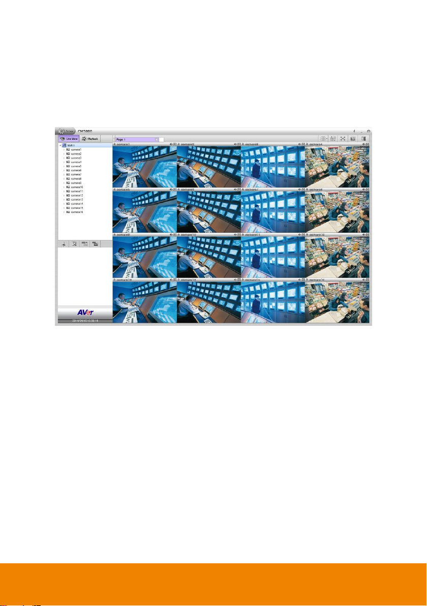
Chapter 1 Introduction
The CM5000 (also call CMS) is a central monitoring system that enables user to monitor up to
16 NVR/DVR servers through an internet connection.
1
Page 9
Chapter 2 CMS Installation
Minimum
Recommended
CPU
Intel Core i5 3.3GHz
Intel Core i7 3.2GHz
Main Memory
1GB
2GB or higher
Video Memory
512MB
1GB or higher
Hard disk
160GB or higher
OS
Windows XP, Windows Vista, Windows 7, Windows 8
Network
10~100 Mbps Ethernet
Others
DirectX 9.0 or above
1. Place the installation CD into the CD-ROM drive then click Install CM5000.
2. Please carefully read the license agreement. Click Yes to accept the agreement.
3. Setup the user name and password for login CM5000.
4. Then, follow the on-screen instructions to complete the installation.
5. When the installation is completed, click Finish.
6. User may now run the CMS program. To run the application, click CM5000 icon ( )
on your PC desktop or click Start> >AVer >CM5000.
This chapter describes how to install the CMS software.
2.1 System Requirements
The system spec requirements for CM5000 are listed in following table:
2.2 Install the CMS Software in Windows
2
Page 10
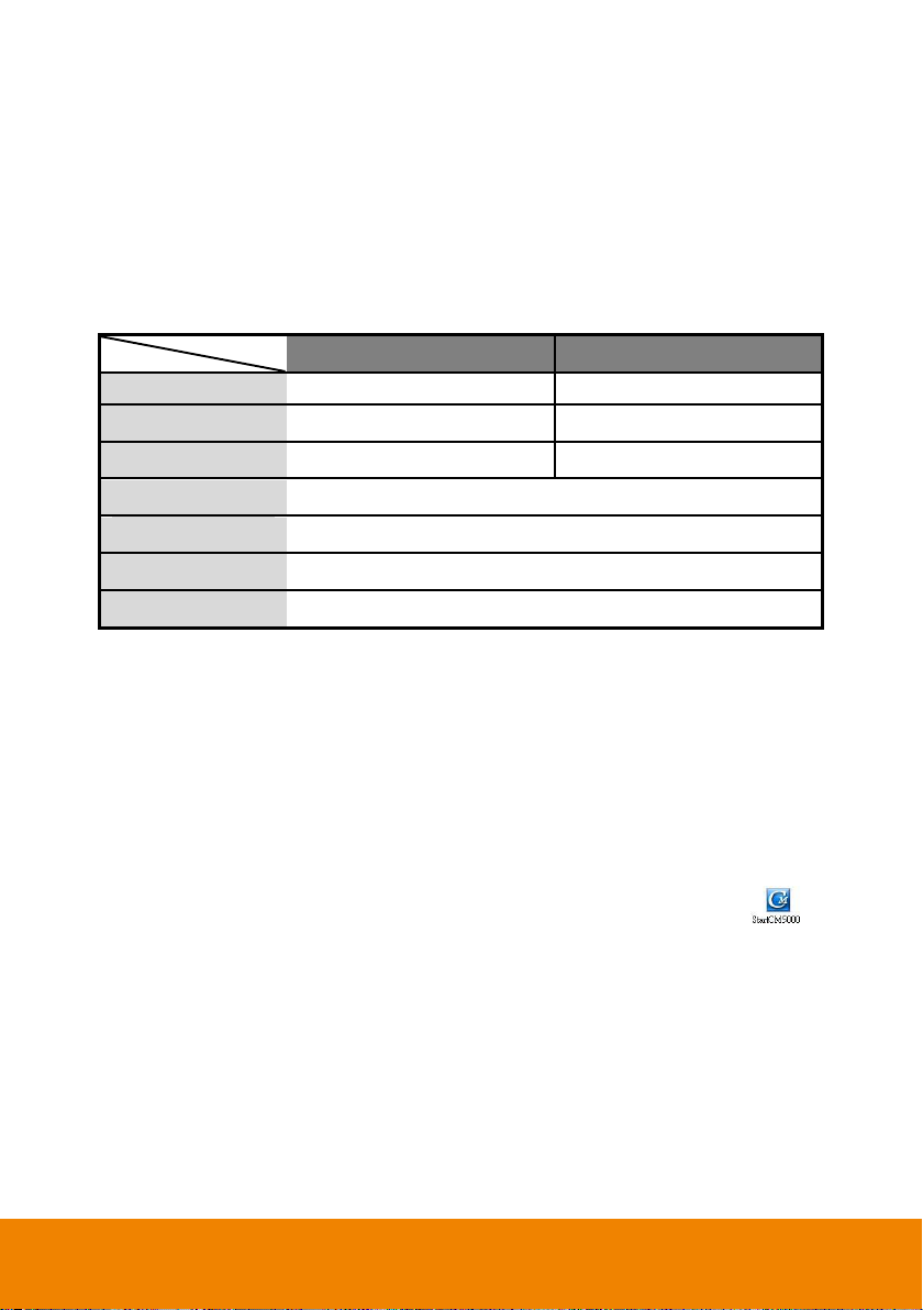
2.3 Run the CMS System
1. Click CM5000 icon ( ) on your PC desktop or click Start> >AVer >CM5000 to run the
CMS application.
2. For the first time login, enter the default ID admin and default password admin. User may
change the login password in User Management(see also Chapter 5.1)
3. After login the CMS system, user should see the preview mode of CMS system.
4. To add the remote NVR/DVR server for monitoring, refer to Chapter 3.
5. To use the CMS system, refer to Chapter 4.
6. To configure the remote NVR/DVR server, refer to Chapter 5.
3
Page 11
Chapter 3 Monitor Remote NVR/DVR
Servers
CMS can monitor up to 1000 NVR/DVR servers. The default is 16 NVR/DVR servers, for more
than 16 NVR/DVR servers monitoring that user needs to purchase the license. Please contact
your local dealer for CMS license purchase.
3.1 Add the NVR/DVR server
There are two ways to add the NVR/DVR for monitoring and configuring. The descriptions will
be in following contents.
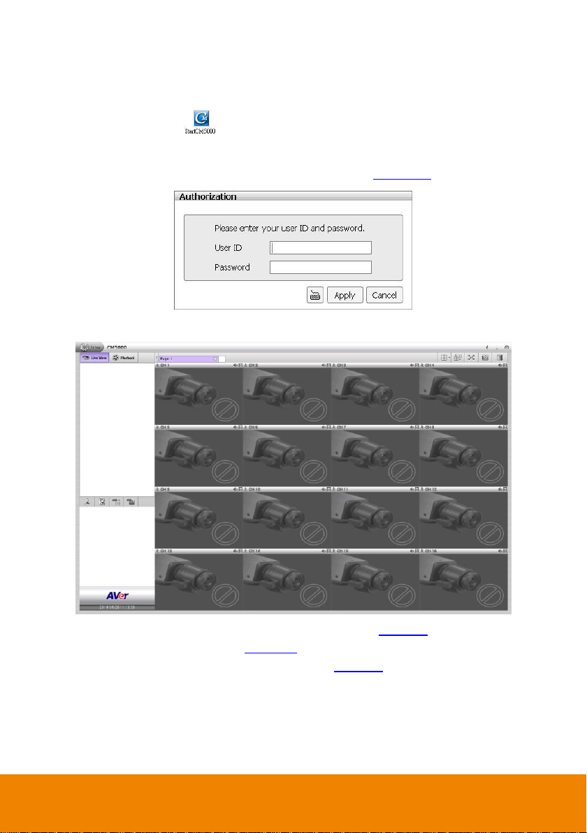
Add a DVR/NVR server by DVR List dialog box
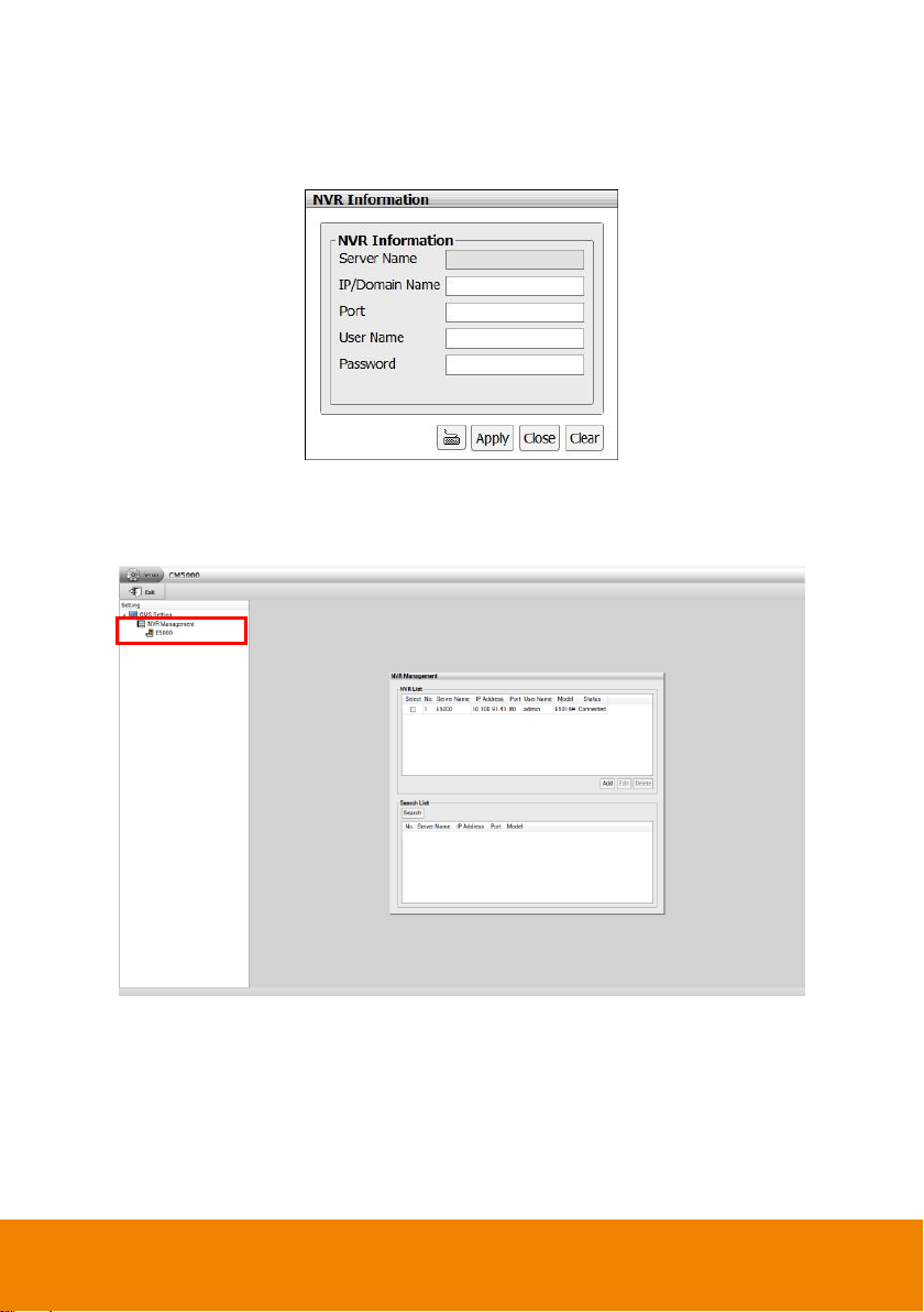
1. In preview UI, click Setup to call out Setup window. In Setup window, click icon of CMS
Setting. Next, select the NVR management and the NVR management page is displayed.
2. Click Add button and NVR Information dialog will appear.
3. Enter the following data in DVR List dialog box.
- Server Name: Name of remote NVR/DVR. The name of NVR/DVR server will display
when CMS system is connected with NVR/DVR server.
- IP/Domain Name: Enter the IP address of DVR/NVR server. Also, user can enter the
domain name instead of IP address if the domain name is available.
4
Page 12
- Port: The network port of DVR/NVR server. The default is 80.
- User Name: The ID uses to login DVR/NVR server.
- Password: The password uses to login the DVR/NVR server.
4. Click Apply to make a connection.
5. When connection is successful, click icon of NVR Management and all connected
NVR/DVR servers are listed.
5
Page 13
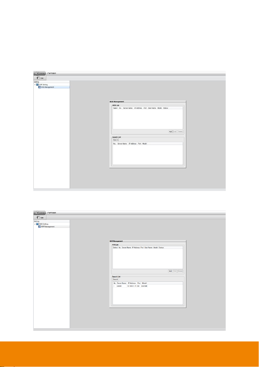
Use Auto Search to add a DVR/NVR server
1. Click Setup tab and click icon of CMS Setting, then, click NVR Management. The
NVR Management dialog will appear on screen.
2. Next, click Search button to start searching remote NVR/DVR servers.
3. After searching has completed, select the NVR/DVR server that has been found by CMS
system and click Add button.
6
Page 14
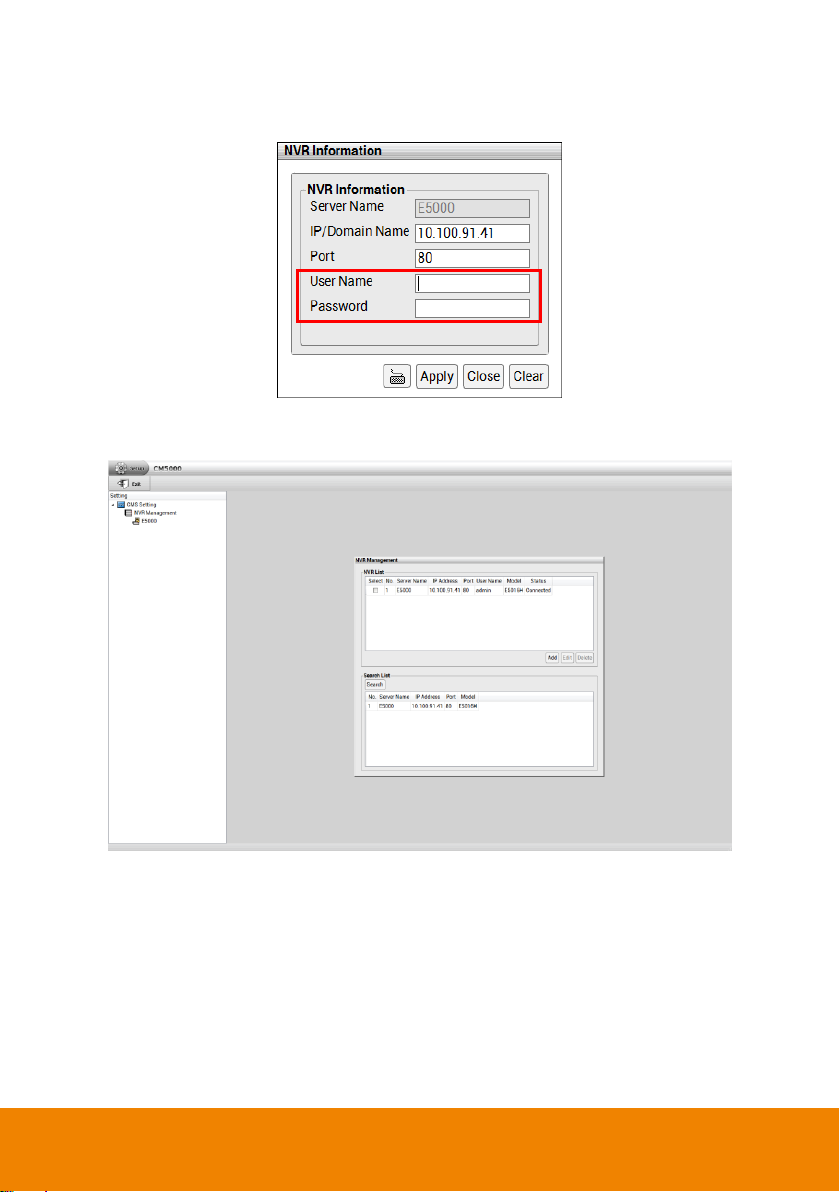
4. The NVR Information dialog will appear. Enter the User Name and Password of remote
NVR/DVR server and click Apply to make a connection.
5. User should see the NVR/DVR server list in DVR List section after connection is
successful.
7
Page 15
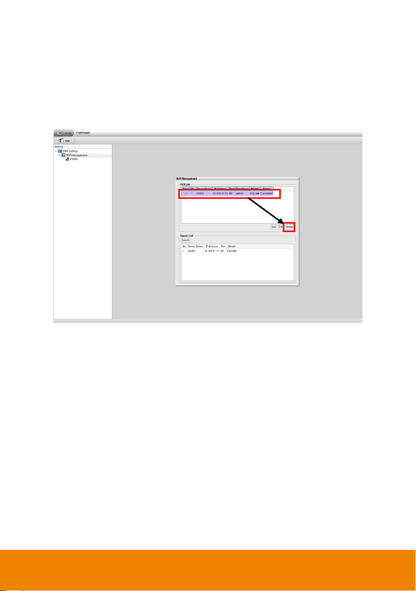
3.2 Delete the NVR/DVR server
1. Click Setup tab and click icon of CMS Setting, then, click NVR Management. The NVR
Management dialog will appear on screen.
2. Select the NVR/DVR server that user wants to delete.
3. Next, click Delete button.
3.3 Edit the NVR/DVR server
1. Click Setup tab and click icon of CMS Setting, then, click NVR Management. The NVR
Management dialog will appear on screen.
2. Select the NVR/DVR server that user wants to edit.
3. Next, click Edit button and the NVR Information dialog will appear.
4. In NVR Information dialog, the NVR/DVR server data is displayed and user can modify the
NVR/DVR server’s information.
5. When is done, click OK to apply the new settings.
8
Page 16
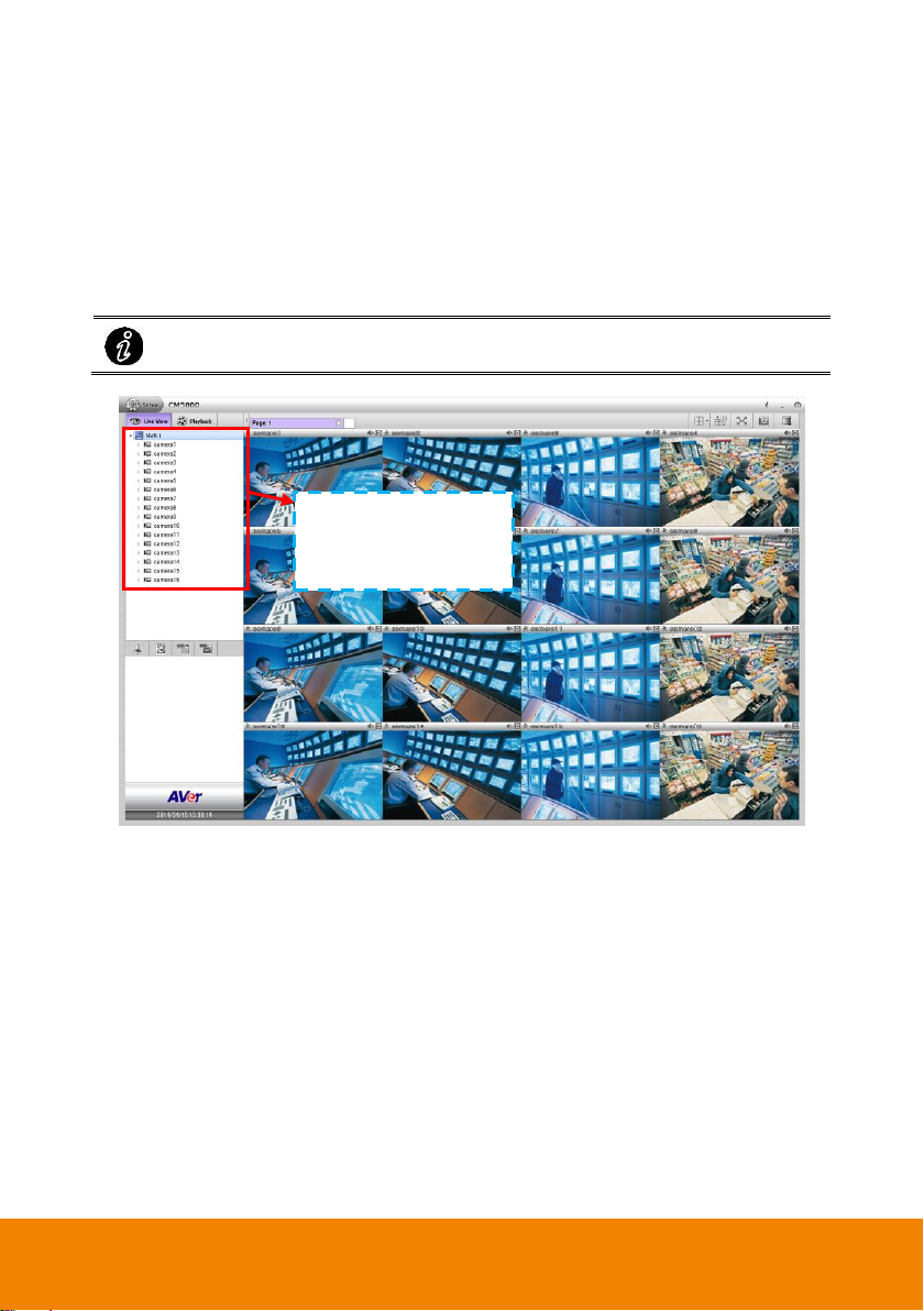
3.4 Monitor the NVR/DVR server
Click and drag the “DVR#” to channel can monitor all cameras of NVR/DVR.
Drag the camera or DVR
to the channel to view live
video of the camera
In CMS system, user can monitor camera channel from different NVR/DVR server. When CMS
system is restart or re-login, CMS system will automatically reconnect the NVR/DVR server.
1. In Preview mode, select the NVR/DVR server and click icon to expand the camera list.
2. Drag the camera that user wants to monitor to the channel screen.
3. User will see the live video of the camera.
9
Page 17
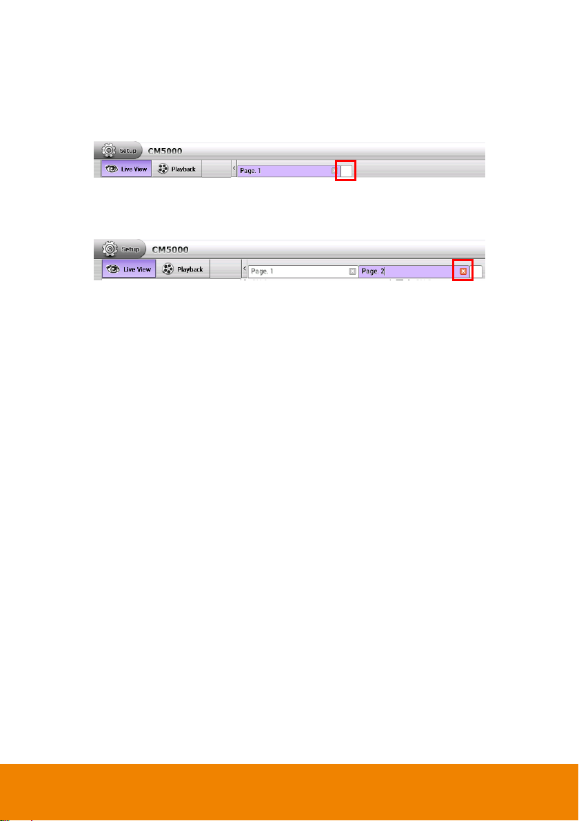
3.4.1 Add/Delete the Monitor Page
In CMS system, user can add up to 4 monitor pages for different monitor combinations.
1. In preview mode, click blank page tab to add a new monitor page.
2. In new monitor page, user can drag the cameras from different NVR/DVR server to
channel screen for monitoring.
3. To delete a monitor page, click X on page tab.
10
Page 18
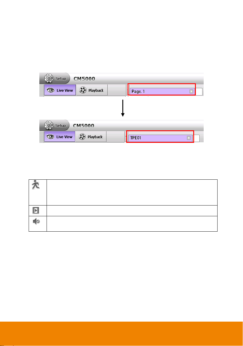
3.4.2 Rename the Monitor Page
Indicates the monitored camera motion recording status on NVR/DVR site.
- Red color: The monitored camera is motion recording on NVR/DVR site.
- Gray color: The monitored camera is not motion recording on NVR/DVR site.
Click to playback the monitored camera live video instantly.
Enable/disable audio play of monitored camera. User can click the icon to enable
or disable the play of audio.
1. Click on text of monitor name (Page #). User should see mouse cursor is flashing.
2. Next, use delete or backspace button on keyboard to erase the original name and enter
the new name.
3. When is done, click anywhere on screen to leave the page tab.
3.4.3 The Icons on Monitored Channels
There are some icons on monitored channels and they are explaining in following.
11
Page 19
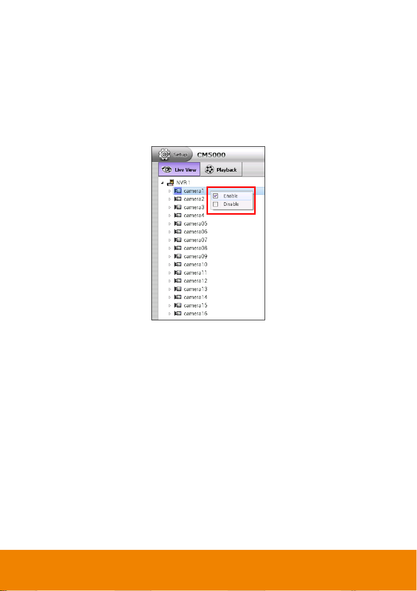
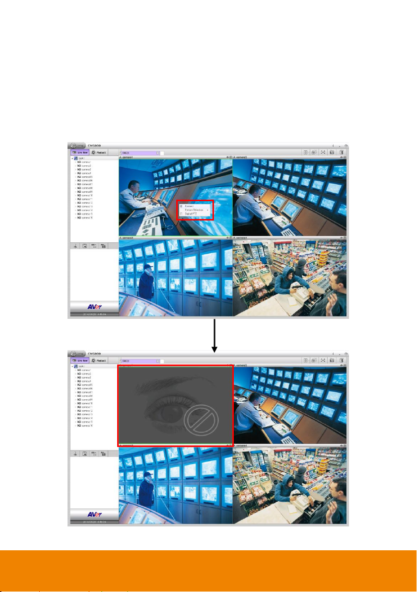
3.4.4 Enable/Disable the Monitored Channel
[Note] This action will apply to remote NVR/DVR site.
In Camera list, user can enable/disable the camera. When camera is disabled, monitor and
record function are both disabled on remote NVR/DVR site. In CMS system, user won’t be able
to see the live video of the camera.
Right-click on the camera in Camera list section, select disable or enable the camera.
12
Page 20
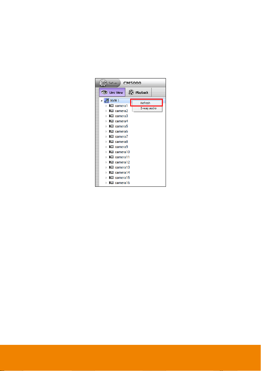
3.4.5 Refresh the Status of Remote NVR/DVR server
[Note] This function can be operated in preview mode only.
The refresh function allows user to update the remote NVR/DVR server status immediately.
Right-click the name of NVR server(ex: NVR 1) in Camera List section and select Refresh.
13
Page 21
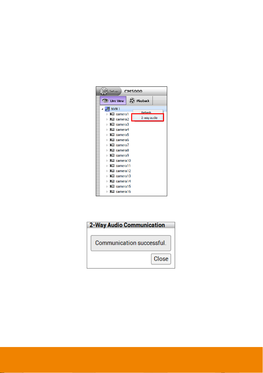
3.4.6 Use 2-way Audio Function
[Note] This function can be operated in preview mode only.
The 2-way audio function allows user to talk to the remote NVR/DVR site through the speaker
and microphone.
Right-click on name of NVR/DVR server in Camera list section and select 2-way audio.
When connection is successful, user should see the communication successful message
dialog is appeared on screen. Click Close button can disconnect the connection.
[Note] 1. If the connection is failed, please check the speaker and microphone is stalled
properly on the PC that runs CM5000.
2. If the remote NVR/DVR server has connected with other device on 2-way audio, then,
the connection will fail, too.
14
Page 22
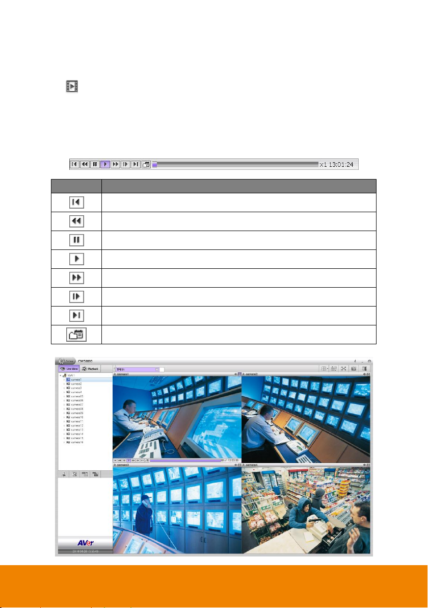
3.5 Playback in Preview Mode
Button
Function
Go to the beginning of video.
Play the recorded video file at the speed of 1/2x, 1/4x, or 1/8x.
Briefly stop playing the recorded video.
Play the recorded video.
Play the recorded video file at the speed of 2x, 4x, 8x, 16x, 32x, or 64x.
Go to the next frame.
Go to the end of video.
Call out the calendar to select the date and time for playback.
Click icon on channel to instantly playback the recorded video on remote NVR/DVR
server in preview mode. User can playback multiple channels at the same time.
Move the mouse cursor on channel screen, the playback tool bar will appear and use it to
control playback status.
Playback tool bar
15
Page 23
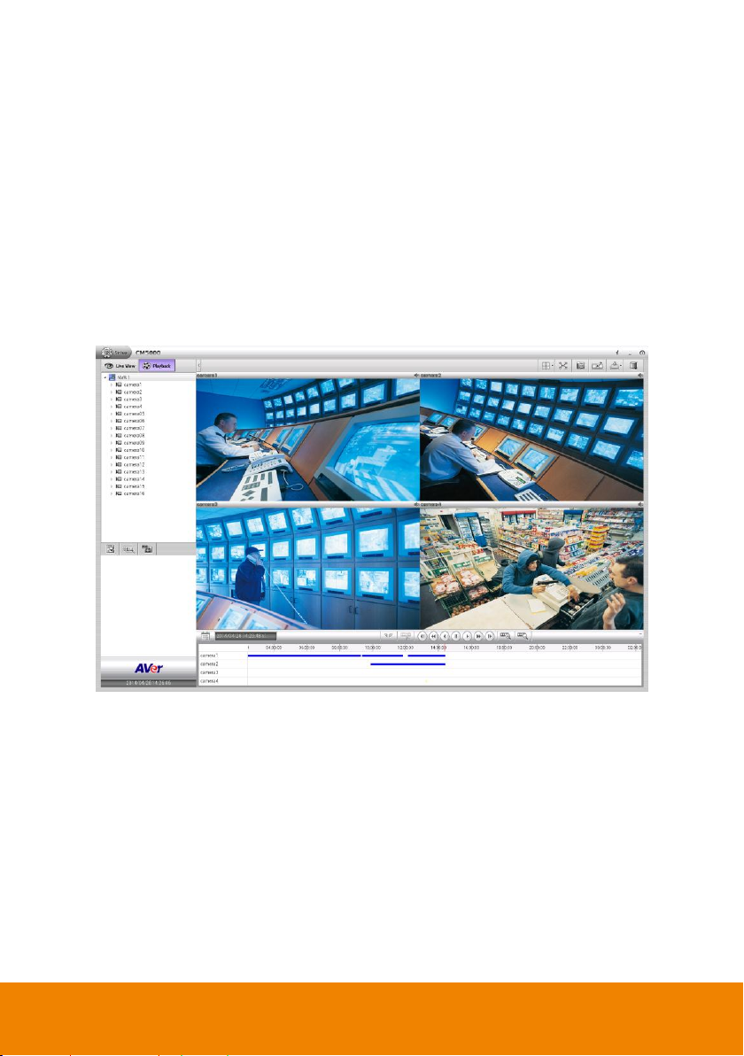
3.6 Playback in Playback Mode
In CMS system, user can view the recorded video of monitored channel which are recorded on
remote NVR/DVR server.
1. Click Playback tab.
2. In playback mode, the CMS will start playback the recorded video from remote NVR/DVR
server. If the remote NVR/DVR server doesn’t record, there is no recorded video for
playback.
3. All monitor pages are playback at the same time when the system switches to the
playback mode.
16
Page 24
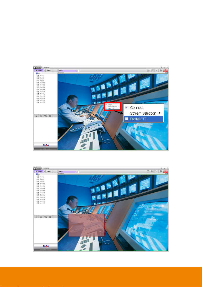
3.7 Digital PTZ Function
[Note] This function can be operated both in preview and playback mode. The following
description is based on preview mode.
The digital PTZ function allows user to enlarge the selected area to view.
1. Right-click on the channel screen and mark Digital PTZ to enable digital PTZ function.
2. When the digital PTZ is enabled, the cursor is changed to cross and user can select an
area to enlarge the view.
17
Page 25
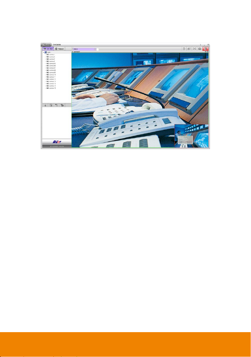
3. The selected area is enlarged and a sub-window is appeared at right bottom of screen.
User can move the gray frame of sub-window to view other area of screen in enlarge view.
4. Right-click on channel screen and un-mark the Digital PTZ can disable the digital PTZ. The
channel screen view will back to normal view.
18
Page 26
3.8 Connect/Disconnect the Monitored Channel
[Note] This function can be operated in preview mode only.
Right-click on monitored channel and un-mark the “Connect” to disconnect the connection.
When the monitored channel is disconnected, the live video cannot be seemed. Mark the
Connection again to bring back the live video view.
19
Page 27
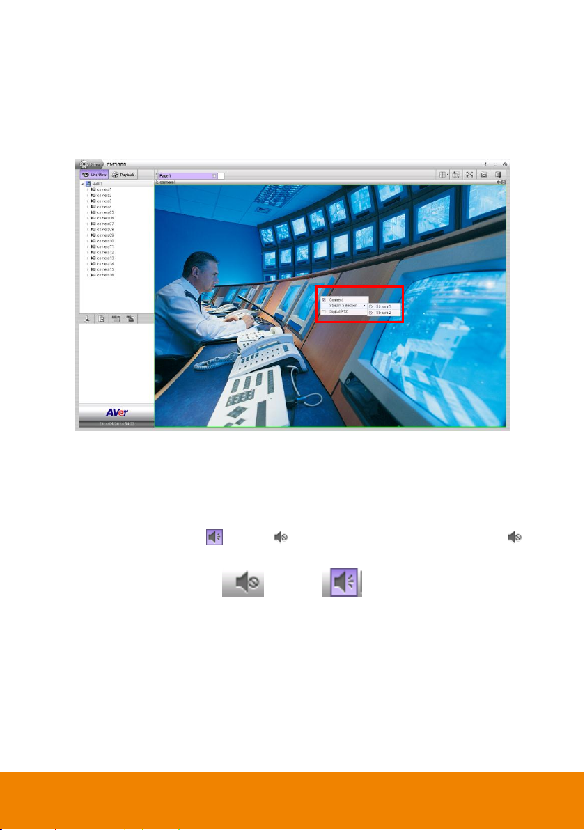
3.9 Select the Stream of Monitored Channel
[Note] This function can be operated in preview mode only.
User can select the stream of monitored channel by right-click on screen channel.
3.10 Enable/Disable the Sound of the Channel
[Note] This function can be operated both in preview and playback mode.
User can click the audio icon ( ) to mute ( ) the sound of channel. Click the audio icon ( )
again to turn on the sound.
audio off audio on
20
Page 28
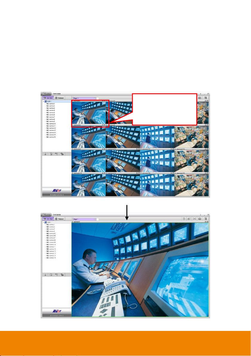
3.11 Switch Multiple Screen to Single Screen Display
Double-clicking on channel
screen can switch to single
screen display mode
immediately.
[Note] This function can be operated both in preview and playback mode. The following
description is based on preview mode.
In multiple screen display mode, user can double-click on the channel screen to switch to
single display screen mode. Double-clicking again on channel screen, the screen display will
switch back to multiple screen display mode.
Preview mode
Preview mode
21
Page 29
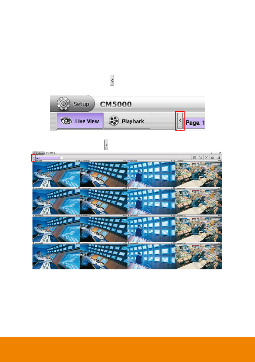
3.12 Hide the Camera List Section
[Note] This function can be operated both in preview and playback mode. The following
description is based on preview mode.
User can hide the camera list section to have larger view of screen.
In preview mode/playback mode, click icon next to preview tab and the camera list will be
hided.
Preview mode
To show the camera list again, click icon.
Preview mode
22
Page 30
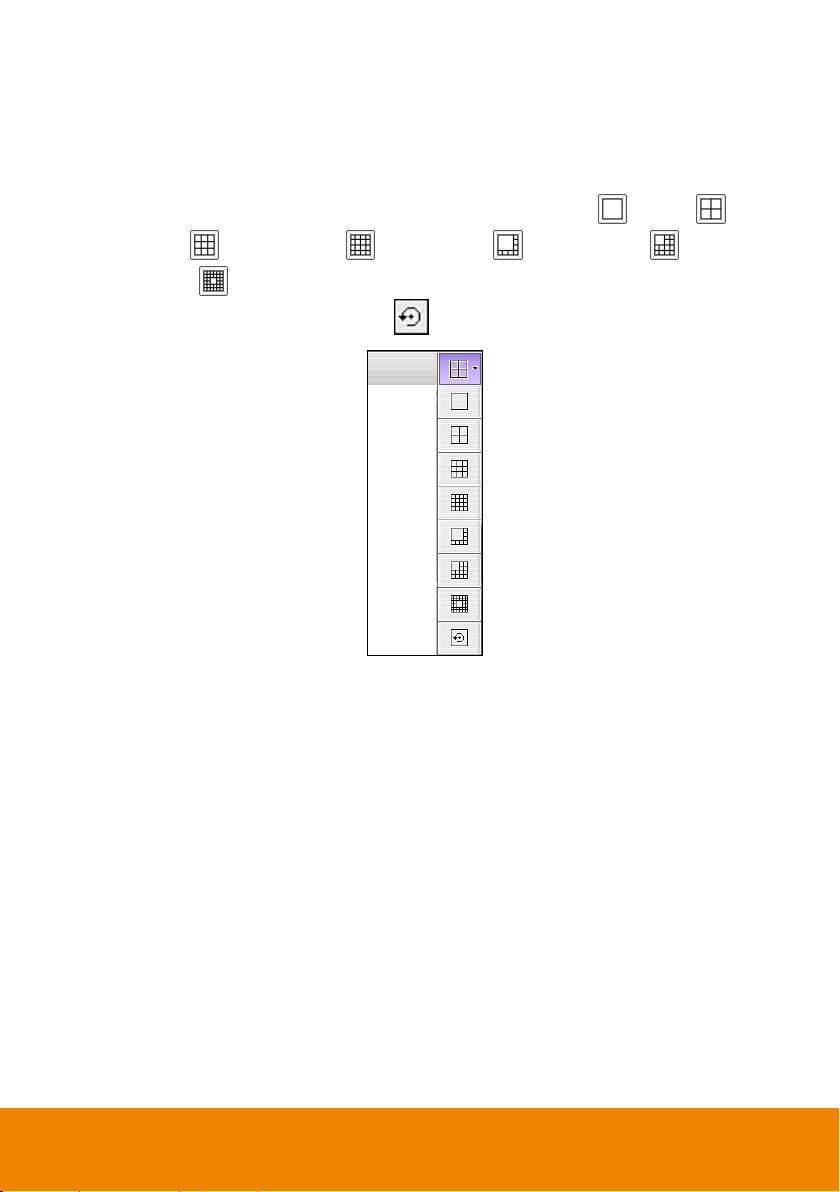
3.13 Screen Channel Display Mode
[Note] This function can be operated both in preview and playback mode.
The CMS system has provided 7 types of screen display mode – single ( ), QUAD ( ),
9-split screen ( ), 16-split screen ( ), 8-split screen ( ), 13-split screen ( ), and
33-split screen ( ). To select the screen display mode, click on the screen display icon.
To reset to default screen mode, select the and all monitored cameras will be cleared.
23
Page 31

Chapter 4 Use the CMS System
(3)
(4)
(5)
(6)
(7)
(8)
(9)
(2) (1) (10)(11)
(12)
(13)
(14)
(16)
(17)
(15)
Name
Function
(1) Playback
Switch to Playback mode. This allows you to view the recorded
video file.
(2) Setup
Click Setup button to configure settings for cameras, recording,
network, scheduler, backup, sensors, relays, alarms and user
authentication (see also Chapter 6).
(3) Preview
Switch to Preview mode. This allows you to view live camera
video.
(4) Camera list
Lists all cameras of NVR. Click + to expand the list. User can
select and drag the camera to video display area to arrange the
monitor layout.
(5) PTZ
To call out a PTZ setup dialog to configure an appointed PTZ
camera (see also Chapter 4.1.2).
The CMS system is divided into 3 parts – preview, playback, and setup mode. Functions of
each mode will be described detail in following chapters.
4.1 Familiarizing Functions of Preview Mode
The preview mode is where user monitors cameras of remote NVR/DVR server and operates
logs, PTZ, E-map, and snapshot function.
24
Page 32

Name
Function
(6) E-map
To load up to 8 desired E-maps in *.JPG and *.PNG image
format, and locate cameras, sensors, and relays to desired
positions (see also Chapter 4.1.1).
(7) Event Log Viewer
Search and display the record of activities that take place in the
system (see also Chapter 4.4.1).
(8) POS Log Viewer
Search and display POS event logs (see also Chapter 4.4.3).
(9) Date and Time
It shows the current system date and time.
(10) Split Screen Mode
It provides 7 kinds of split display modes for your selection. User
can select the split display modes by clicking the split mode
icon. To reset all monitored cameras, select and all
camera channels will be cleared.
To only display one of the video in the multiple-screen mode, double click on the
video screen you only want to display.
(11) AutoScan
Click it to start auto cycle display each channel.
(12) Full screen
Use the entire area of the screen to only display the video. To
return, press the right button of the mouse or ESC on the
keyboard or click the arrow icon.
Click it to return back
to normal display
25
Page 33

Name
Function
(13) System Information
Click it to view NVR system’s version and copyright.
(14) Minimize
Minimizing the CMS system in system tray.
(15) Power button
Call up the Power dialog box.
In the Power dialog box, user may do the following:
- Exit: To shutdown the CMS system.
- Compact: Switch to compact mode(see also Chapter 4.3).
- Cancel: To exit Power dialog box.
(16) Alarm
Click Alarm Status button to view the alarm event and search
alarm event(see also Chapter 4.4.1)
(17) Snapshot
Catch a static recording image and save it as a JPG or PNG file
in USB pen drive device(see also Chapter 4.5)
26
Page 34

4.1.1 E-map Setting
Holds up to 64 maps in *.jpg and *.PNG format. The map is hierarchy in structure and users
can add a map on another map. User also may add the DVR icons on the map.
1. Click (E-map) icon in preview mode.
2. The E-map dialog box will appear in the left corner of preview screen.
3. Click icon on E-map dialog box to expand the E-map dialog box on the preview
screen.
4. Click Edit button to switch to E-map setup mode.
27
Page 35

5. Then, click the Map number (1 to 8) that user want to setup.
6. Next, click icon to setup name of E-map and load a map figure. When the E-map
Setting dialog box appears, click the open file icon ( ) to locate and select the map.
Enter a name for this E-map in Name column. Click OK to save the setting.
28
Page 36

7. When the inserted map appears on the E-map screen, user may now drag the NVR icons
to its place on the map. Icons on the map can be relocated anywhere. If user is going to
locate the icon on the map to other area, click Edit button and right-click on the NVR icon
on the E-map and click remove to put the NVR icon back to the Resource list.
8. Also, user can add a map layer under the map (map 1~8). Select the map (map 1~8) and
click icon to add a map layer under the selected map. Enter a name for the new map
layer. In E-map Setting dialog box, select Remote to add a map save in CMS site and
select DVR to put the map of remote site on map. Then, click to locate the map
image file to insert it. Click OK to save the setting. The map icon represents the
map of remote NVR/DVR server. The map icon represents the map of CMS. To
modify the map, select the map layer and click icon.
29
Page 37

9. When the inserted map appears on the map list, user can relocated the map icon
anywhere on the map. Double-click on map icon; it will switch to the map layer. To delete
the map layer, select the map layer and click button to delete the map layer. When
setup is done, click OK to save the setting.
10. To exit E-map mode, click icon.
11. When alarm occurred, the icons on the map will turn to flash status.
30
Page 38

12. On the map, right-click NVR icon can view the live video and reset alarm of remote
NVR/DVR server.
NVR/DVR Live Preview on Emap
13. Also, user can view remote camera’s live video by right-click on camera icon on the Emap.
31
Page 39

Remote camera live preview
32
Page 40

4.1.2 Using the PTZ Control Panel
(5)(6)(7)
(4)
(3)
(2)
(1)
(9)
(8)
Name
Function
(1) Camera preset
position number
Move the PTZ camera to the preset point.
User can control PTZ camera through PTZ control panel in preview mode. Enable and set up
the PTZ camera; refer to chapter of Setup PTZ Camera Function.
1. Select the camera has PTZ function enabled.
2. Next, click (PTZ) icon to call out PTZ control Panel in preview mode.
3. The functions’ description of PTZ control panel is as following.
33
Page 41

Name
Function
(2) Group AutoPan
Select to automatically operate PTZ camera in group.
(3) Direction buttons’
moving speed
Adjust the moving speed of the PTZ camera lens. This speed will
apply to the (11) Direction buttons’ moving speed only.
(4) Setup
Call out the PTZ setup window. The PTZ functions are same PTZ
setup in Camera setting, refer to Setup Camera PTZ function.
(5) AutoPan
Operate the PTZ cameras automatically based on the selected
camera group preset position number. User needs to select the (2)
Group AutoPan, then, click (5) Auto Pan button.
(6) Zoom +/-
Zoom in and out the image.
(7) Focus +/-
Adjust the focus manually to produce clear image.
(8) Camera ID
Display the PTZ camera number that is being operated.
(9) Direction buttons
Move and position the focal point of the PTZ camera. The support of
direction button depends on the PTZ camera.
34
Page 42

4.2 Familiarizing Functions of Playback Mode
(2)
(3)
(4)
(5)
(10)
(6)
(7)
(8)
(9)
(1)
(12)
(11)
(13)
(14)
(18)
(19)
(20)
(21)
(22)
(23)
(24)
(25)
(15)
(17)
(16)
Name
Function
(1) Playback
Switch to Playback mode. This allows you to view the recorded
video of monitored cameras.
(2) Setup
Click Setup button to configure settings for cameras, recording,
network, scheduler, backup, sensors, relays, alarms and user
authentication(see also Chapter 6)
(3) Preview
Switch to Preview mode. This allows you to view live camera
display.
(4) Camera list
Lists all cameras of NVR. Click + to expand the list.
(5) E-map
To load up to 8 desired E-maps in *.JPG and *.PNG image
format, and locate cameras, sensors, and relays to desired
positions (see also Chapter 4.1.1).
(6) Searching
CMS supports 2 types of searching in playback mode:
- Event Search: Search from the recorded activities that were
recorded in event log such as Sensor, Motion, Video Loss
(see also Chapter 4.2.1).
- Visual Search: Search from a specific camera by Date, Hour,
Minute, 10 Seconds and Second (see also Chapter 4.2.2).
Click playback tab to switch to playback mode.
35
Page 43

Name
Function
(7) POS Log Viewer
Search and display POS event logs (see also Chapter 4.4.3).
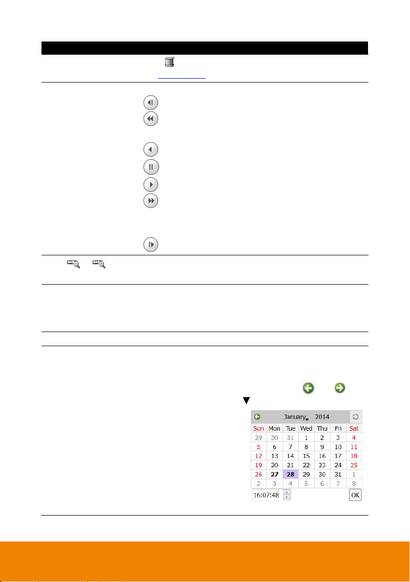
(8) Status bar
Display the recorded date, time and play speed.
(9) Date
Select the date on the calendar and the time to where to start
playing the recorded video file.
–
Date: click the date on calendar to select. The date in bold
text indicates there has recorded file. Click and icon
to switch the date or click icon next to month to select the
month. To switch the year, click on the text of year and click
spin button to select.
– Time: In Time box, select the hour, minute, and second to
setup the playback start up time.
(10) Date and Time
It shows the current date and time.
(11) Split Screen Mode
Select from 7 kinds of split screen type to playback the recorded
video file of all the camera, or one camera over the other or
alongside on a single screen. To reset all monitored cameras,
select and all camera channels will be cleared.
To only display one of the video in the multiple-screen mode, double click on the
video screen you only want to display.
36
Page 44

Name
Function
(12) Full screen
Use the entire area of the screen to only display the video. To
return, press the right button of the mouse or ESC on the
keyboard or click the arrow icon.
When you switch to full screen in multiple-screen mode, Left
click to toggle to only display one of the video in the
multiple-screen mode or all.
(13) Snapshot
Catch a static recording image and save it as a *.JPEG or *.PNG
file in pen drive device or local hard disk drive (see also Chapter
4.5).
(14) Bookmark
Mark a reference point when reviewing the recorded video file to
which you may return for later reference (see also Chapter
4.2.3).
(15) Backup
Save the playback file to USB pen drive or local hard disk (see
also Chapter 4.2.4).
(16) System Information
Click it to view CMS system’s version and copyright.
(17) Minimize
Minimizing the CMS system in system tray.
Click to switch
back to normal
display mode.
37
Page 45

Name
Function
(18) Power button
Call up the Power dialog box.
In the Power dialog box, user may do the following:
- Exit: To shutdown the CMS system.
- Compact: Switch to compact mode (see also Chapter 4.3).
- Login: To login in different account. Default user ID is
admin and password is admin.
- Cancel: To exit Logout dialog box.
(19) Alarm Log Viewer
Click button to view and search the alarm event logs (see
also Chapter 4.4.2.).
(20) (Segment)
Keep a portion of the recorded video to repeat playback; also
can output the segment video to the pen drive device.
Click the button to set the segment video. User can drag
the triangle mark to set the video segment (see also Chapter
4.2.6).
(21)
Save the segmented video file in *.avi format (see also Chapter
4.2.6).
(22) Playback Control
Buttons
From left to right order:
Previous: Go back to the previous frame.
Slower: Play the recorded video file at the speed of 1/2x,
1/4x, or 1/8x. The playback speed will show on the screen.
Rewind: Wind back the recorded video file.
Pause: Briefly stop playing the recorded video file.
Play: Play the recorded video file.
Faster: Play the recorded video file at the speed of 2x, 4x,
8x, 16x, 32x, or 64x. The playback speed will show on the
screen.
Next: Go to the next frame.
38
Page 46

Name
Function
(23) /
(Zoom in/Zoom out)
To expand the playback time bar from an hour to minute.
(24) Hide the progress
bar
Click to close up the progress bar. Click again to open up.
(25) Progress bar
Show the progress of the file being played. You may move the
bar to seek at any location of the track.
Using the Zoom In/Out button ( / ) to expand the
playback time from an hour to minute.
Meaning of color in progress bar:
- Red: Sensor record
- Green: Motion record
- Blue: Always record(normal record)
- Yellow: Video loss
- White: No record data
39
Page 47

4.2.1 Using the Event Search
User can click icon to expand the Event Log Viewer dialog box on the screen.
In playback mode, user can use Event Search to find the specific event to playback.
1. Select the channel that user wants to search.
2. Click (Search) icon, then select (Event Search) icon. The Event Search
dialog box would appear at side area.
3. In the Event Search dialog box, check the type of condition user wants to search. Then, set
the Start Date/Time and End Date/Time.
4. Next, click OK to start searching.
5. When the Event list appears, click and select the item user wants to view; but not all the
events can be playback such as Sensor.
6. To close the Event Search dialog, click icon.
40
Page 48

4.2.2 Using the Visual Search
In playback mode, user can use Visual Search to find the specific time to playback.
1. Click (Search) icon, then select (Visual Search) icon. The Visual Search
dialog box would appear under the area.
2. In the Visual Search dialog, select the date. Click and icon to switch the month or
click icon next to month to select the month. To switch the year, click on the text of year
and click spin button to select.
3. Next, setup the search time period by clicking spin buttons to setup the hour, minute, and
second.
4. Then, click Search to start searching.
41
Page 49

5. When a series of frames appear by date, click on the frame to display another series of
frames and search by every 2 Hours of that date, every 8 minutes of that hour, and every
30 seconds of that minute. Using and to go to hour, minute, and second page.
6. To playback the selected video, click button or double-click on selected video screen.
42
Page 50
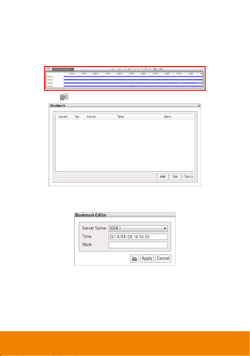
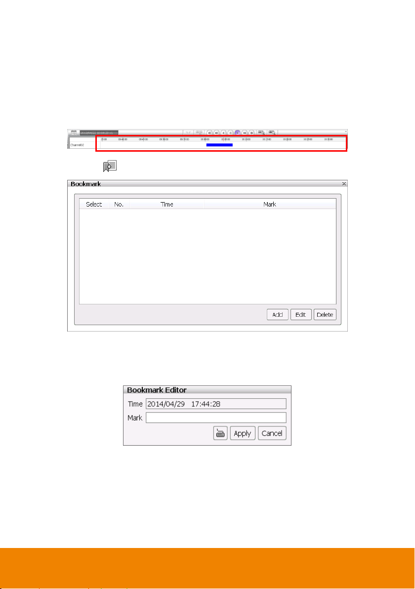
4.2.3 To Bookmark a Section of the Video
User can bookmark a specific time of video section.
1. Using the mouse to move the playback time progress bar to the time that user wants to
bookmark.
2. Then, click icon. The Bookmark dialog box is appeared on the screen.
3. Click Add button to create the new reference mark in the bookmark list. Enter a short
description or name for the mark and click Apply button to save the bookmark. To exit
bookmark Editor dialog box, click Cancel button.
43
Page 51

4. Select and click one in the bookmark list to review the file.
5. To modify the bookmark, select the bookmark and click Edit button.
6. To delete the bookmark, select the bookmark and click Delete button.
7. To close the Bookmark dialog box, click icon.
44
Page 52

4.2.4 Backup the Playback Video
4.2.4.1 Manual Backup
Backup the recorded files to external USB pen drive or local hard disk drive. In Manual Backup
dialog box, user can select different channels or time period to backup at the same time. The
backup files can be playback on PC by Qplayer application which is included when user select
to include player while backup. Play backup file on PC refer to Chapter 4.2.5.
1. Click Playback tab to switch to playback mode.
2. Click Backup ( ) button and select Manual backup ( ). Then, the Manual Backup
dialog box is appeared.
3. In Manual Backup dialog box, select the following settings:
Channel: Select the channels that user wants to backup. Mark All to select all
channels.
Select date and time: Select the date and time period that user wants to backup.
Include Player when backup: Including the player for playback the backup file on PC.
Backup File Size: Display the total size of the backup file. If there are more one
backup file, there will be total size of all backup files. Click Calculate Size button to
calculate.
Backup Path: Selecting a save path for backup file.
4. After selecting the backup file conditions, click OK to start backup.
45
Page 53

5. User can backup multiple recorded file (different channels and different time period) at the
same time. Repeat the above steps to create the backup file and click Add button. The
multiple backup files limit is 3 files at the same time.
6. When all backup files have created, click OK button to start archiving the selected file to
USB pen drive or local hard disk drive.
46
Page 54

4.2.4.2 Schedule Backup
Set a backup schedule on selected NVR/DVR server, channel, and time; the backup action will
be executed on schedule time everyday.
Schedule backup is operated as following rules:
Each NVR/DVR server only can be backup one schedule task at a time.
CMS system can perform 3 backup schedule tasks (different NVR/DVR server) at a time.
When one schedule task is completed, the following schedule task will start.
When backup schedule is completed, the schedule task will be removed from Processing
Task list.
All completed schedule tasks are shown on Report page.
Schedule task will be removed when:
- There is no recorded data to backup.
- The network connection is loss.
- User has deleted the backup schedule.
1. Click Playback tab to switch to playback mode.
2. Click Backup ( ) button and select Schedule backup ( ). Then, the Schedule
Backup dialog box is appeared.
47
Page 55

3. Set the storage path. Before starting to set the backup schedule, user needs to set a
storage path.
Select Storage Setting tab. In Storage Setting page, click Add button and browse the
storage path location to add a storage path. The storage path can have more than one but
at least one storage path is required for backup.
In Storage Setting page, user can setup logs data and hard disk space recycle. Click
Apply to save the settings.
Delete Recorded Data After Days: If user wants the system to automatically
erase the data after a certain days, enable the Delete Recorded Data After check
box and enter the numbers of days in Days text box.
Delete Log Data After Days: If you want the system to automatically erase the
event and alarm log after a certain days, enable the Delete Log Data After check
box and enter the numbers of days in Days text box.
Recycle: Mark to over write hard disk from older data when hard disk space is full.
48
Page 56

4. Set the backup schedule. Click Schedule tab. In Schedule page, click Add button to set
a backup schedule.
In Task Setting dialog box, select the time, NVR/DVR server, camera, data time and
backup path. Click Apply to save the backup schedule. Click Cancel to back to the
Schedule page.
Process This Task at Everyday: Select the backup time to process on every day.
The time period is based on 24 hours.
Server Name: Select the NVR/DVR server that user wants to backup.
49
Page 57

Camera: Select the camera channel of NVR/DVR server that user wants to backup.
Backup Time: Click radio button of Enable and click the hour (00 – 23) to select the
hours that want to backup. The selected hours will be backup on daily.
Resume backup task if interrupted/not completed: When backup process has
interrupted. The backup task is moved to the bottom of processing task list and wait to
process backup task again. The backup resume will perform 5 time; unless the below
conditions:
a. The backup schedule is deleted.
b. The backup task is deleted.
c. The storage path is deleted.
d. There is not record data on remote NVR/DVR server.
e. The remote NVR/DVR server is deleted.
f. The backup task is resumed 5 times.
Download QPlayer: Include the Qplayer application while backup.
Backup Path: Select the storage path for saving backup data. The storage path must
be set before setting up the backup schedule.
50
Page 58

Backup Data Period: Select the backup time on weekly. Click Weekly View button
When schedule status is disable, the backup schedule won’t be able to execute;
click the drop-down list and select Enable.
can view the whole week backup schedule.
User should see the all backup schedules at Schedule page. To modify the backup
schedule, select the schedule and click Modify button. Click Delete button to remove the
selected schedule from schedule list.
51
Page 59

5. In Processing Task page, user can view all the processing backup schedule tasks. When
schedule task is completed, this schedule task will be removed from processing task list.
Double-click on processing schedule task, user can view the schedule detail information,
but user cannot modify the schedule.
6. In Report page, user can view all completed backup schedule tasks.
52
Page 60

4.2.5 Using the QPlayer to Playback Backup File
You can playback the backup files by using QPlayer applications on the PC. When you back up
the recorded file, QPlayer applications are automatically included in the backup folder if user
has enabled the selection of Inculde player when backup when backup recorded file. With
QPlayer, it is similar in Playback mode and supports different split screen types to view all the
video at the same time.
To run the application, go to backup folder and select Qplayer folder, then, double-click
Qplayer.exe.
4.2.5.1 Familiarizing Functions of Qplayer
In Qplayer main UI, click File ( )> Open File to locate the backup file folder and a File List
dialog box will show. Double-click on the file that wants to playback in File List dialog box to
start playback selected file.
53
Page 61

The functions of Qplayer will be described in following:
(1)
(2)
(3)
(4)
(5) (6)(7) (8) (9)
(10)
(12)
(16)
(17)
(11)
(18)
(13)
(14) (15)
Name
Function
(1) File
Click it to open the backup file.
(2) Split Screen Mode
Select from 7 kinds of split screen type to playback the recorded
video file of all the camera, or one camera over the other or
alongside on a single screen.
To only display one of the video in the multiple-screen mode, double click on the
video screen you only want to display.
(3) Camera list
Lists all cameras. Click + to expand the list. User can select and
drag the camera to desire channel location.
(4) Date and Time
It shows the current date and time.
(5) Export
Export function includes 2 functions – Snapshot and Print.
- Snapshot: Catch a static current screen image and save it
as a *.JPEG or *.PNG file on local hard disk.
- Print: Print out the current Qplayer screen.
(6) Bookmark
Mark a reference point when reviewing the recorded video file to
which you may return for later reference (see also Chapter
4.2.5.2).
(7) File list
Click it to call out file list dialog box. To close file list dialog box,
click x icon.
54
Page 62

Name
Function
(8) Full screen
Use the entire area of the screen to only display the video. To
return, press the right button of the mouse or ESC on the
keyboard or click the arrow icon.
When you switch to full screen in multiple-screen mode, Left
click to toggle to only display one of the video in the
multiple-screen mode or all.
(9) System Information
Click it to view CMS system’s version and copyright.
(10) Minimize
To minimize the Qplayer on the task tray.
(11) Power button
Call up the Power dialog box.
In the Power dialog box, user may do the following:
- Exit: To shutdown the CMS system.
- Cancel: To exit Logout dialog box.
Click to switch
back to normal
display mode.
55
Page 63

Name
Function
(12) On Screen
Keyboard
If the keyboard is not available, you may use the Virtual
Keyboard.
(13) Status bar
Display the recorded date, time and play speed.
(14) Playback Control
Buttons
From left to right order:
Previous: Go back to the previous frame.
Slower: Play the recorded video file at the speed of 1/2x,
1/4x, or 1/8x. The playback speed will show on the screen.
Rewind: Wind back the recorded video file.
Pause: Briefly stop playing the recorded video file.
Play: Play the recorded video file.
Faster: Play the recorded video file at the speed of 2x, 4x,
8x, 16x, 32x, or 64x. The playback speed will show on the
screen.
Next: Go to the next frame.
(15) /
(Zoom in/Zoom out)
To expand the playback time bar from an hour to minute.
(16) Close up progress
bar
Click to close up the progress bar. Click again to open up.
(17) Progress bar
Show the progress of the file being played. You may move the
bar to seek at any location of the track.
Using the Zoom In/Out button to expand the playback time from
an hour to minute.
Meaning of color in progress bar:
- Red: Sensor record
- Green: Motion record
- Blue: Always record(normal record)
- Yellow: Video loss
- White: No record date
56
Page 64

Name
Function
(18) Calendar
Select the date on the calendar and the time to where to start
playing the recorded video file. Click OK to start playback.
–
Date: click the date on calendar to select. The date in blod
text indicates there has recorded file. Click and icon
to switch the date or click icon next to month to select the
month. To switch the year, click on the text of year and click
spin button to select.
– Time: In Time box, select the hour, minute, and second to
setup the playback start up time.
57
Page 65
4.2.5.2 Bookmark a Section of the Video for Playback
User can bookmark a specific time of video section.
1. Using the mouse to move the playback time progress bar to the time that user wants to
bookmark.
2. Then, click icon. The Bookmark dialog box is appeared on the screen.
3. Click Add button to create the new reference mark in the bookmark list. Enter a short
description or name for the mark and click Apply button to save the bookmark. To exit
bookmark Editor dialog box, click Cancel button.
58
Page 66

4. Select and click one in the bookmark list to review the file.
5. To modify the bookmark, select the bookmark and click Edit button.
6. To delete the bookmark, mark the bookmark and click Delete button.
7. To close the Bookmark dialog box, click icon.
59
Page 67

4.3 Compact Mode
The preview and playback are both supported compact mode. To switch to Compact mode,
click power button (located at upper right corner) and select Compact button in Power dialog
box.
To switch back to Advance mode, click power button and select Advanced button.
The following chapters will describe the function buttons on preview and playback compact
mode.
60
Page 68

4.3.1 Familiarizing Function in Preview Compact Mode
Name
Function
(1) Setup
Click Setup button to configure settings for cameras, recording,
network, scheduler, backup, sensors, relays, alarms and user
authentication(see also Chapter 6).
(2) Split Screen Mode
It provides 6 kinds of split display modes for your selection. User
can select the split display modes by clicking the split mode
icon. To reset all monitored cameras, select and all camera
channels will be cleared.
- When the NVR system is in multiple-screen mode, user can click the video
screen of the camera and Drag on where user wants to relocate it.
- To only display one of the video in the multiple-screen mode, double click on the
video screen user only wants to display.
(3) AutoScan
Click it to start auto cycle display each channel.
61
Page 69

Name
Function
(4) Full screen
Use the entire area of the screen to only display the video. To
return, click the arrow icon at bottom of right.
When you switch to full screen in multiple-screen mode, Left
click to toggle to only display one of the video in the
multiple-screen mode or all.
(5) Snapshot
Catch a static recording image and save it as a *.JPG and
*.PNG file in USB pen drive device or local hard disk drive (see
also Chapter 4.2.7).
(6) System Information
Click it to view CMS system’s version and copyright.
(7) Minimize
Minimizing the CMS system in system tray.
(8) Power button
Call up the Power dialog box.
In the Power dialog box, user may do the following:
- Exit: To shutdown the CMS system.
- Advanced: Switch to preview mode (advanced mode).
- Login: To login in different account. Default user ID is admin
and password is admin.
- Cancel: To exit Power dialog box.
(9) Alarm Log Viewer
Click button to view and search the alarm event logs (see
also Chapter 4.4.2).
Click to switch
back to normal
display mode.
62
Page 70

4.3.2 Familiarizing Function in Playback Compact Mode
Name
Function
(1) Setup
Click Setup button to configure settings for cameras, recording,
network, scheduler, backup, sensors, relays, alarms and user
authentication(see also Chapter 6).
(2) Split Screen Mode
It provides 7 kinds of split display modes for your selection. User
can select the split display modes by clicking the split mode
icon. To reset all monitored cameras, select and all camera
channels will be cleared.
- When the NVR system is in multiple-screen mode, user can click the video
screen of the camera and Drag on where user wants to relocate it.
- To only display one of the video in the multiple-screen mode, double click on
the video screen user only wants to display.
63
Page 71

Name
Function
(3) Full screen
Use the entire area of the screen to only display the video. To
return, press the right button of the mouse or ESC on the
keyboard or click the arrow icon.
When you switch to full screen in multiple-screen mode, Left
click to toggle to only display one of the video in the
multiple-screen mode or all.
(4) Snapshot
Catch a static recording image and save it as a *.JPG and
*.PNG file in USB pen drive device or local hard disk drive.
(5) Bookmark
Mark a reference point when reviewing the recorded video file to
which you may return for later reference (see also Chapter
4.2.3).
(6) Backup
Save the playback file to USB pen drive or local hard disk (see
also Chapter 4.2.4).
(7) System Information
Click it to view NVR system’s version and copyright.
(8) Minimize
Minimizing the CMS system in system tray.
(9) Power button
Call up the Power dialog box.
In the Power dialog box, user may do the following:
- Exit: To shutdown the CMS system.
- Advance: Switch to preview mode (advance mode).
- Cancel: To exit Power dialog box.
Click to switch
back to normal
display mode.
64
Page 72
Name
Function
(10) Alarm Log Viewer
Click button to view and search the alarm event logs (see
also Chapter 4.4.2).
(11) Playback Control
Buttons
From left to right order:
Previous: Go back to the previous frame.
Slower: Play the recorded video file at the speed of 1/2x,
1/4x, or 1/8x. The play speed will show on the screen.
Rewind: Wind back the recorded video file.
Pause: Briefly stop playing the recorded video file.
Play: Play the recorded video file.
Faster: Play the recorded video file at the speed of 2x, 4x,
8x, 16x, 32x, or 64x. The play speed will show on the
screen.
Next: Go to the next frame.
(12) /
(Zoom in/Zoom out)
To expand the playback time bar from an hour to minute.
(13) Progress bar
Show the progress of the file being played. You may move the
bar to seek at any location of the track.
Using the Zoom In/Out button to expand the playback time from
an hour to minute.
(14) Status bar
Display the recorded date, time and play speed.
(15) Date
Select the date on the calendar and the time to where to start
playing the recorded video file.
–
Date: click the date on calendar to select. The date in blod
text indicates there has recorded file. Click and icon
to switch the date or click icon next to month to select the
month. To switch the
year, click on the text of
year and click spin button
to select.
– Time: In Time box, select
the hour, minute, and
second to setup the
playback start up time.
65
Page 73

4.4 Log Viewer
User can click icon to expand the Event Log Viewer dialog box on the screen.
Show the record of activities (alarm, event, iPOS) that take place in the system. User can view
and search for specific log. The following descriptions and figures are based on preview mode.
4.4.1 Use the Event Log Viewer
The event log viewer is supported in preview mode only.
1. Click the Event Log Viewer ( ) button in preview mode.
2. The Event Log Viewer dialog box is appeared and located at bottom of left side screen.
66
Page 74

3. To filter the logs, select and click the select Type -- System, Network, Operation, Event,
or All.
4. Set the Start Date/Time and End Date/Time period to search the logs.
5. User also can search specific logs by specific Keyword.
6. Click Search button to start searching. The search results are displayed in the below
column. Click More button to display more event logs.
67
Page 75

7. Click on the event log can view the log video. The screen will switch to Event log playback
screen.
8. Click Export button can output the log result list to local hard disk drive or external USB
pen drive in *.cvs file format.
68
Page 76

4.4.2 Use the Alarm Log Viewer
User can click icon to expand the Alarm Log Viewer dialog box on the screen.
The alarm log viewer is both supported in preview and playback mode.
Viewing the Alarm Event
Alert and display warning information.
1. Click Alarm ( ) button on preview or playback mode.
2. The Alarm Log Viewer dialog box is appeared and located at bottom of left side screen.
3. Then, click Event tab to view all alarm events.
69
Page 77

4. Clicking Alarm reset button to reset all alarm event status.
5. Clicking Refresh button to refresh the alarm events list.
6. Double-click on alarm event can playback the event video.
70
Page 78

Search the Alarm Event Logs
User can click icon to expand the Alarm Log Viewer dialog box on the screen.
Searching the specific alarm event.
1. Click Alarm ( ) button on preview or playback mode.
2. The Alarm Log Viewer dialog box is appeared and located at bottom of left side screen.
3. Then, click Search tab in Alarm Log Viewer dialog box.
4. In Alarm Log Viewer dialog box, select the Camera that user wants to search. Multiple
cameras selection is allowed.
71
Page 79

5. Set the searching period at Start Date/Time and End Date/Time column.
6. Searching by specific keyword, enter the keyword in Keyword column.
7. Click Search button to start searching.
8. The search result will list in below column. Click More button to display more event logs.
9. Click Export button can save the search result list to external USB pen drive.
10. Double-click on alarm event can playback the event video.
72
Page 80

4.4.3 Use the POS Log Viewer
User can click icon to expand the POS Log Viewer dialog box on the screen.
Search the iPOS event.
1. Click POS Log Viewer ( ) button on preview or playback mode.
2. The POS Viewer dialog box is appeared and located at bottom of left side screen.
3. In POSViewer dialog box, select the Camera that user wants to search.
4. Set the searching period at Start Date/Time and End Date/Time column.
5. Searching by specific keyword, enter the keyword in Keyword column. Mark Match whole
words exactly option to 100% match the keyword that user has entered.
6. Click Search button to start searching. The search result will list in below column. Click
More button to display more event logs.
7. Click Export button can save the search result to external USB pen drive.
73
Page 81

4.5 Snapshot the Screen
Taking a quick capture of current display screen and save in *.jpg and *.PNG format to local
hard disk.
1. In preview or playback mode, Click the snapshot icon ( ) and the save as dialog box is
appeared.
2. User can rename the File name. Default file name is “snapshot.jpg”.
3. Select the save location.
4. Click Save button to save the captured image file to selected location.
5. The captured screen is looks like the figure below.
Preview mode
74
Page 82

Chapter 5 Customize the CMS System
User can setup language of CMS system, export/import configuration file, manage user
accounts, and monitor setting.
Click Setup tab to call out Setup window. Click Exit button will close the Setup window and
back to preview window.
75
Page 83

5.1 Setup the Language of CMS System
1. Click Setup tab to call out setup mode of CMS system.
2. In CMS Setting dialog box, select the system language from Language drop-down list.
3. Click Apply to save the setting.
5.2 Import/Export the System Configuration
Click Setup tab to call out setup mode of CMS system.
Import: To regain the same settings back from previously backup configuration file.
Export: Backup a copy of all the settings and allows user to regain the same settings back.
76
Page 84
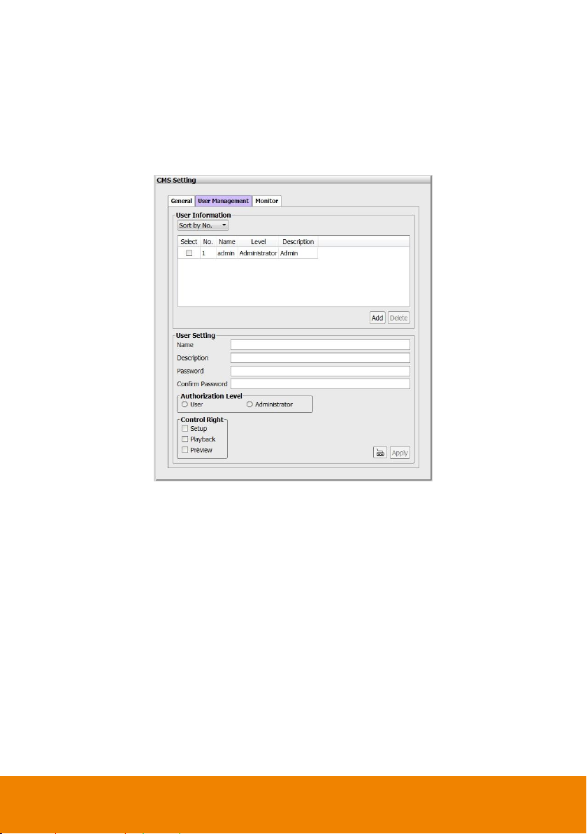
5.3 User Account Management
User can create the user accounts for logging to CMS system.
1. Click Setup tab to call out setup mode of CMS system.
2. In CMS Setting page, click User Management tab.
3. Enter the Name, Description, Password, and Confirm Password for the new user
account.
4. Select the Authorization Level – User or Administrator.
5. Select the Control Right – Setup, Playback or Preview. The user level authority is
preview in default.
6. Click Apply to create the account.
77
Page 85

7. The user accounts are listed in User Information section.
8. To create another user account, click Add to clear previous enter information and repeat
above steps.
9. To delete the user account, select the user account and click Delete button.
78
Page 86

5.4 Setup Monitor
The CMS system supports up to 4 monitors. User can setup each monitor for different display.
Click Setup tab to call out setup mode of CMS system. In CMS Setting page, click Monitor tab.
The CMS system will detect the monitors automatically. User can set each monitor to display
different function of UI – Preview, Playback, Emap, Alarm, POS, Event Log. Only preview UI
can be set in multiple monitors. Emap, Alarm, Event log, POS button only show in main monitor
(Monitor 1).
79
Page 87

Chapter 6 Customize the Remote
NVR/DVR Server
CMS system allows user to setup and modify settings of monitored NVR/DVR servers.
1. Click Setup tab to call out setup mode of CMS system.
2. Click of CMS Setting and click of NVR Management to expand the NVR/DVR server
list.
3. Select the NVR/DVR server that user wants to configure and switch to the NVR/DVR
server setup window.
4. To backup CMS setup window, click Back buton.
80
Page 88

6.1 Configure the Remote NVR/DVR Server
6.1.1 System Setup
1. Click Setup tab to call out setup mode of CMS system.
2. Click of CMS Setting and click of NVR Management to expand the NVR/DVR server
list.
3. Select the NVR/DVR server that user wants to configure and switch to the NVR/DVR server
setup window.
In Setup mode, user should see the System Information dialog box is displayed at the first
place. In System Information dialog box, it displays the information of Server name, Current
Firmware Version, IPCam Module, Received Bandwidth, Transmitting Bandwidth, and
Temperature.
The setup sections are divided into System Setting, Camera Management, Recording
Management, Alarm Setting, User Setting, and Schedule Setting.
In the following chapters will describe all.
81
Page 89

General System Setting
Setup the language of NVR system, video type, system date and time, synchronize the system
time.
In System Configuration dialog box, click General tab. After changing the settings, click Apply
button to save the settings. To un-save the new settings, click Cancel button.
Language: Customize the system to display the tool tips and dialogs based on the
selected language. By default the language is in English.
Date/Time: Select the date and time where NVR is located. Click and icon to
switch the month or click icon next to month to select the month. To switch the year, click
on the text of year and click spin button to select.
Video Format: Change and select the proper video system according to your camera
video system. If the video system setting is wrong, the video would appear abnormal.
Synchronize with Time Server: Adjust the NVR system time same as network time
server.
Time Server: Fill in the Time Server IP address or domain name.
Automatic synchronize at: Select Automatic Synchronize time to set automatic
synchronize time on a daily basis.
Update Now: User can click Update Now button to adjust time right away.
82
Page 90

System Advanced Setting
In Advanced of System Configuration, user can setup the daylight saving time, system login
setting, and some other system related setting.
In System Configuration dialog box, click Advanced tab.
After changing the settings, click Apply button to save the settings. To un-save the new
settings, click Cancel button.
83
Page 91

Daylight Saving Time Setting
User can setup daylight saving mode as user is desired.
1. Select the mode of Daylight saving.
Mode 1: Mode 1 is setting up specific start date/time and end date/time.
Mode 2: Mode 2 is setting up fixed day of month in every year for start and end
date/time.
2. Setup the Star Date/Time and End Date/Time for Daylight saving period.
3. Daylight Bias: Assign a time that it is for daylight saving time offset in your time zone. For
example: if the time zone is in U.S. Eastern, the time offset is 1 hour.
4. Click Apply to save the setting.
84
Page 92

Customize System Login Setting
Enable the conditions in Login section you want the system to automatically carry out. Click
Apply to save the setting.
Auto Login after system boot up: Execute the NVR when the operating system is
started.
Default user: Automatically log in to the selected default user when the NVR system is
executed.
85
Page 93

Customize System Miscellaneous Setting
Enable the conditions in Miscellaneous section you want the system to perform. Click Apply
to save the setting.
Auto Scan Period: Set the time gap of the Auto Scan function from 3 to 10 seconds. This
automatically switches to the next video in cycle depending on the set time gap.
Playback Mode:
Select the mode of playback the video.
Select date and time: Select the date and time which user wants to playback.
Play the last file: Automatically playback the video from the last hour
Instant Playback: Automatically playback the video which has just recorded.
Date Format: Select the date format which wants to display in Select date and time
playback mode
86
Page 94

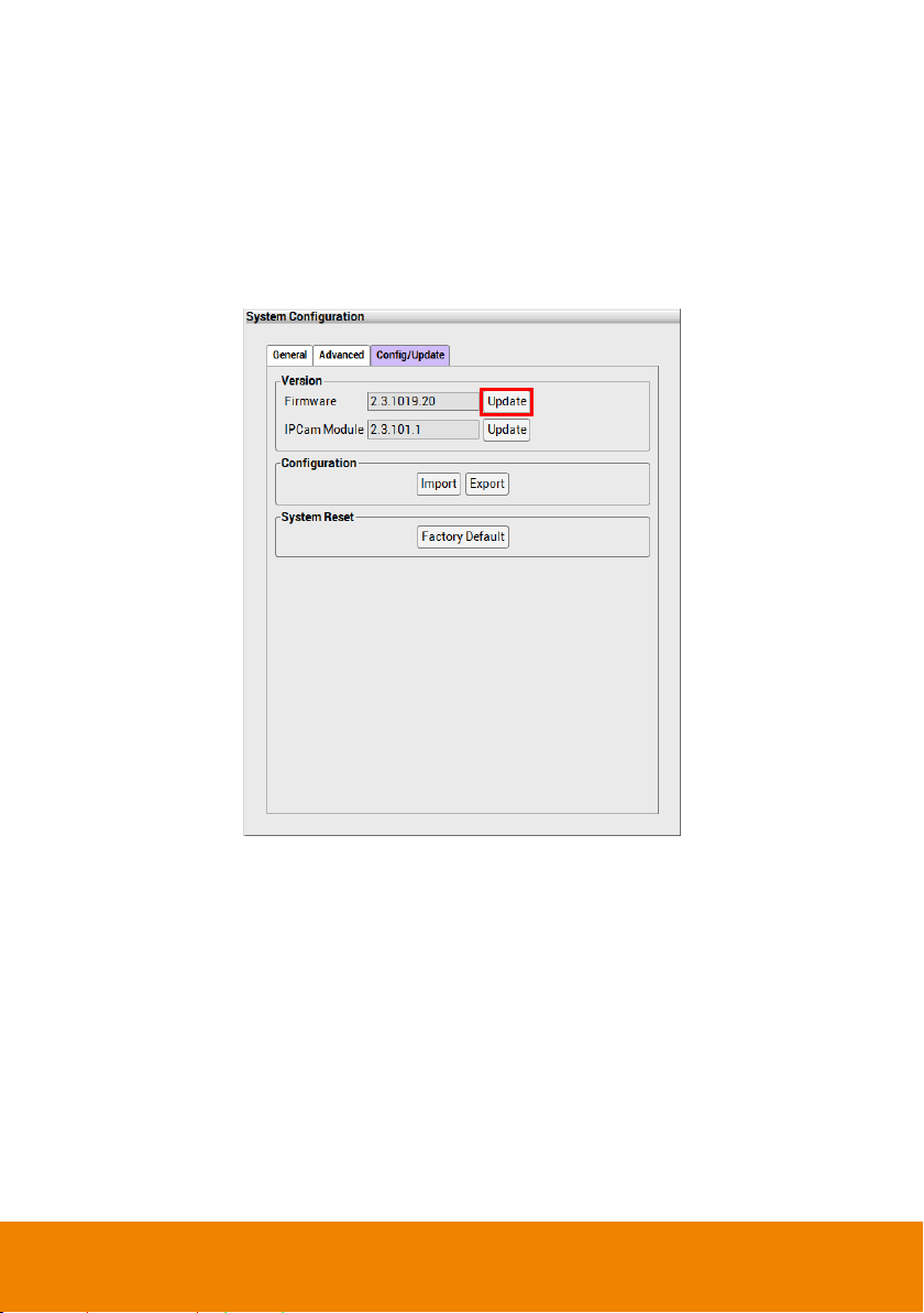
Update Configuration
In Configure Update, user can import the backup configure file to NVR system and export the
configure file. Also, user can update the NVR system’s firmware and IP camera patch file.
In System Configuration dialog box, click Configure/Update tab.
87
Page 95
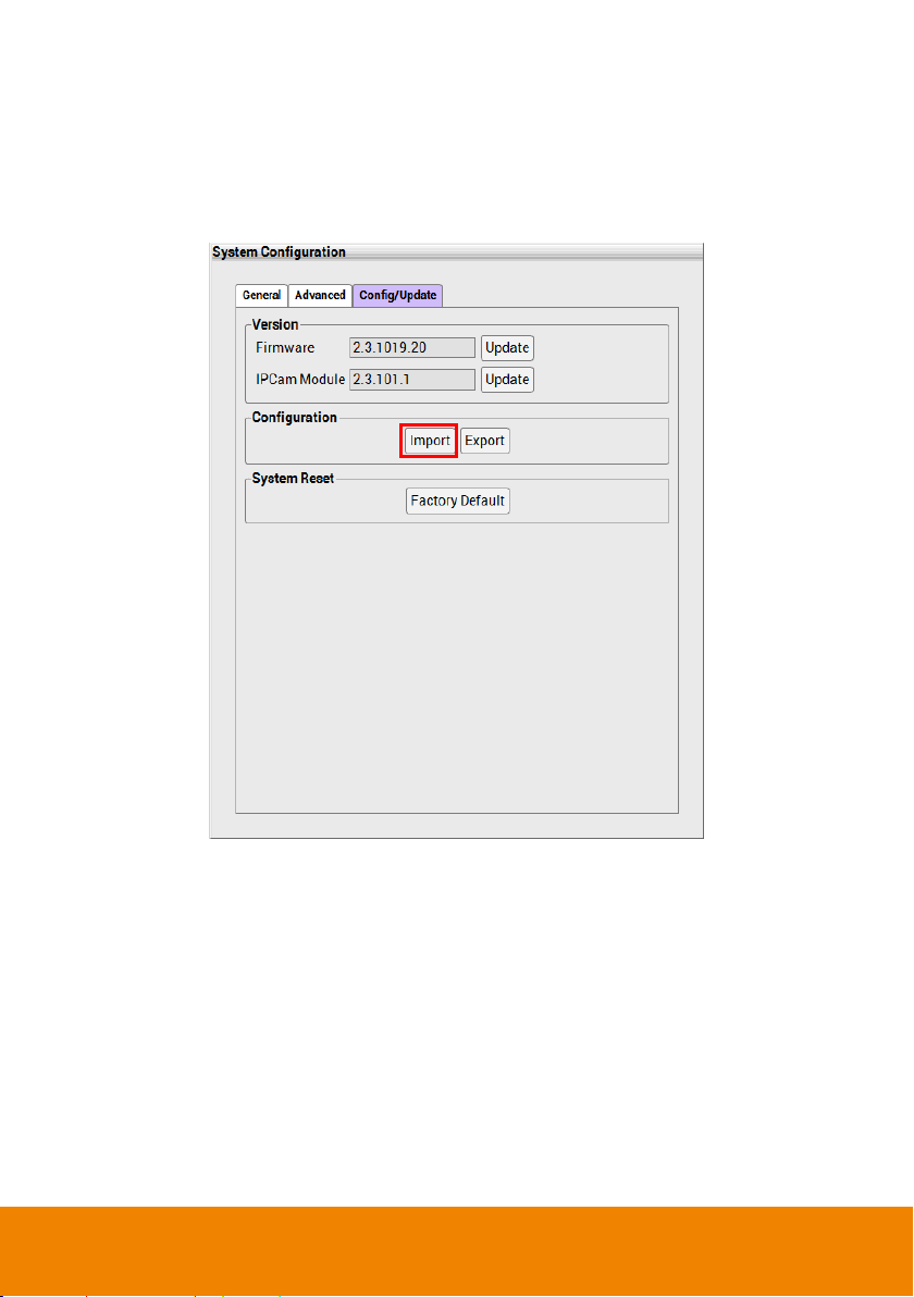
Import the NVR System Configuration
To regain the same settings back from previously backup configuration file.
1. Copy the backup configuration file that user has exported previously to PC.
2. In Configure/Update page, click Import button in Configuration section.
3. In Import dialog box, select the backup configuration file path.
4. Then, click Import button to import the configuration file.
88
Page 96

Export the NVR System Configuration
Backup a copy of all the settings and allows you to regain the same settings back.
1. In Configure/Update page, click Export button in Configuration section.
2. In Export dialog box, select the save path for saving the backup configuration file.
3. Next, click Export button.
4. To restore the backup configuration file to NVR system, refer to chapter of Import the NVR
System Configuration.
89
Page 97

Upgrade the NVR Firmware
To update the firmware of NVR system.
1. Plug the USB pen drive that contains the NVR firmware file or copy the firmware file to local
hard disk drive. To get the newest NVR firmware, go to website http://www.aver.com >
Support > Download center.
2. In Configure/Update page, click Update button of Firmware.
3. In upgrade dialog box, locate the firmware file. The system will check the firmware file and
shows the firmware file name and version information.
4. Click Upgrade button to process.
90
Page 98
Upgrade the IP Camera Module Patch
To update the firmware of NVR/DVR system.
1. Plug the USB pen drive that contains the IP camera patch file or copy the firmware file to
local hard disk drive..
2. In Configure/Update page, click Update button of IPCam Module.
3. In upgrade dialog box, locate the IP camera patch file. The NVR system will check the
patch file and show the patch file name, and version information.
4. Click Upgrade button to process.
91
Page 99

Reset to Factory Default
Reset the NVR/DVR system back to factory default value. All configurations will be lost after
reset to factory default.
Click Factory Default button of System Reset and NVR/DVR system will reboot automatically.
92
Page 100

6.2.2 Network Setting
Do Not assign the NVR server to 1.0.0.0 network segment. It will be caused the
NVR cannot access to Internet due to the un-recognize to 1.0.0.0 IP segment.
Select type of IP mode, setup the IP address of NVR/DVR, and configure the DDNS.
1. In Network dialog box, click Networking 1 tab.
2. MAC Address: Displays the MAC address of Ethernet port on LAN card.
3. Select the IP mode – Static IP, DHCP, PPPOE.
Static IP: Assign a fixed IP address for NVR server
- IP ADDRESS: Assign a constant IP address which a real IP addresses given from
ISP.
- Mask: It is a bitmask used to identify the sub network and how many bits provide
room for host addresses. Enter the subnet mask of the IP address which user has
assigned to NVR system.
- Gateway: A network device act as a passageway to internet. Enter the network
gateway IP address
- DNS: Domain Name Server translates domain names (such as www.abb.com.tw)
to IP addresses. Enter the IP address of DNS if it is available.
DHCP: Uses DHCP server assigning NVR server an IP address.
93
 Loading...