

CAM520 Pro2
User Manual

Federal Communications Commission Statement
NOTE: This equipment has been tested and found to comply with the limits for a Class A
digital device, pursuant to part 15 of the FCC Rules. These limits are designed to provide
reasonable protection against harmful interference when the equipment is operated in a
commercial environment. This equipment generates, uses, and can radiate radiofrequency energy and,
if not installed and used in accordance with the instruction manual, may cause harmful interference to
radio communications. Operation of this equipment in a residential area is likely to cause harmful
interference in which case the user will be required to correct the interference at his own expense.
FCC Caution: Any changes or modifications not expressly approved by the party responsible for
compliance could void the user's authority to operate this equipment.
This device complies with part 15 of the FCC Rules.
Operation is subject to the following two conditions:
(1) This device may not cause harmful interference, and
(2) this device must accept any interference received, including interference that may cause undesired
operation.
Warning:
This is a class A product. In a domestic environment this product may cause radio interference in
which case the user may be required to take adequate measures.
This Class A digital apparatus complies with Canadian ICES-003.
DISCLAIMER
No warranty or representation, either expressed or implied, is made with respect to the contents of this
documentation, its quality, performance, merchantability, or fitness for a particular purpose. Information
presented in this documentation has been carefully checked for reliability; however, no responsibility is
assumed for inaccuracies. The information contained in this documentation is subject to change
without notice.
In no event will AVer Information Inc. be liable for direct, indirect, special, incidental, or consequential
damages arising out of the use or inability to use this product or documentation, even if advised of the
possibility of such damages.
TRADEMARKS
“AVer” is a trademark owned by AVer Information Inc. Other trademarks used herein for description
purpose only belong to each of their companies.
COPYRIGHT
©2021 AVer Information Inc. All rights reserved.
All rights of this object belong to AVer Information Inc. Reproduced or transmitted in any form or by any
means without the prior written permission of AVer Information Inc. is prohibited. All information or
specifications are subject to change without prior notice.

NOTICE
WARNING
lens holder to move the camera.
zinc) or
- Do not attempt to short-circuit the battery terminals.
SPECIFICATIONS ARE SUBJECT TO CHANGE WITHOUT PRIOR NOTICE. THE INFORMATION
CONTAINED HEREIN IS TO BE CONSIDERED FOR REFERENCE ONLY.
To reduce risk of fire or electric shock, do not expose this appliance to rain or moisture.
Warranty will be void if any unauthorized modifications are done to the product.
Do not drop the camera or subject it to physical shock.
Use correct power supply voltage to avoid damaging camera.
Do not place the camera where the cord can be stepped on as this may result in fraying or
damage to the lead or the plug.
Hold the bottom of the camera with both hands to move the camera. Do not grab the lens or
Remote Control Battery Safety Information
- Store batteries in a cool and dry place.
- Do not throw away used batteries in the trash. Properly dispose of used batteries through
specially approved disposal methods.
- Remove the batteries if they are not in use for long periods of time. Battery leakage and
corrosion can damage the remote control. Dispose of batteries safely and through approved
disposal methods.
- Do not use old batteries with new batteries.
- Do not mix and use different types of batteries: alkaline, standard (carbon-
rechargeable (nickel-cadmium).
- Do not dispose of batteries in a fire.
CAUTION
- Risk of explosion if battery is replaced by an incorrect type.
- Dispose of used batteries in a safe and proper manner.

MORE HELP
support.usa@aver.com
For FAQs, technical support, software and user manual download, please visit:
Global: https://www.aver.com/HelpCenter/conferencing-collaboration
USA: https://www.averusa.com/business/support/
European Headquarters: https://www.aver.com/download-center/
Technical Support:
Global: https://aver.com/technical-support
USA: https://averusa.force.com/support/s/contactsupport
European Headquarters: https://www.avereurope.com/technical-support/
Contact Information
Global
AVer Information Inc.
https://www.aver.com
8F, No.157, Da-An Rd.,
Tucheng Dist.,
New Taipei City 23673,
Taiwan
Tel: +886 (2) 2269 8535
USA
AVer Information Inc.
https://www.averusa.com
668 Mission Ct.,
Fremont, CA 94539
Tel: +1 (408) 263 3828
Tol l -free: +1 (877) 528 7824
Technical support:
European Headquarters
AVer Information Europe B.V.
https://www.avereurope.com
Westblaak 140, 3012KM,
Rotterdam, Netherlands
Tel: +31 (0) 10 7600 550
Technical support:
eu.rma@aver.com

Contents
Package Contents ................................................................................................... 1
Product Introduction ................................................................................................ 2
Overview ......................................................................................................... 2
Remote Control ............................................................................................... 3
Pan and Tilt Angle ........................................................................................... 6
Installation ............................................................................................................... 7
Device Connection .......................................................................................... 7
Power Connection ........................................................................................... 8
RS232 Connection .......................................................................................... 9
Wall Mount Installation .................................................................................. 15
Ceiling Mount Installation (Optional) ............................................................. 18
Secure the Cables ......................................................................................... 21
Operating the Camera .......................................................................................... 22
Make a Video Call ......................................................................................... 22
Make a Connection through the Browser ............................................................ 22
Web Settings ................................................................................................... 26
First Time Login ............................................................................................. 26

Set up the Preset ........................................................................................... 28
User can set 10 preset positions. .................................................................. 28
Select the Preset Position ............................................................................. 30
Camera Settings ............................................................................................ 31
Tracking Mode ....................................................................................... 32
Framing Speed ...................................................................................... 34
Smart Frame Preset Point ..................................................................... 35
Auto Focus ............................................................................................ 36
Camera Focus ....................................................................................... 37
Home Position ....................................................................................... 37
Sleep Position ........................................................................................ 38
Sleep Timer ........................................................................................... 38
On Screen Menu ................................................................................... 39
Camera Binding ..................................................................................... 39
Save Preset ........................................................................................... 40
Image Settings .............................................................................................. 41
Image Flip .............................................................................................. 41
Image Mirror .......................................................................................... 41
True WDR .............................................................................................. 42

Frequency .............................................................................................. 42
White Balance ....................................................................................... 43
Noise Reduction .................................................................................... 43
Brightness .............................................................................................. 44
Saturation .............................................................................................. 45
RS232 Setting ....................................................................................... 46
Video Format Settings ................................................................................... 47
H.264 Profile .......................................................................................... 47
IP Stream Resolution ............................................................................. 48
Frame Rate ............................................................................................ 49
Bit Rate .................................................................................................. 49
RTSP ..................................................................................................... 50
RTMP ..................................................................................................... 52
Network Settings ........................................................................................... 53
DHCP ..................................................................................................... 53
Static IP .................................................................................................. 53
System Settings ............................................................................................ 54
Language ............................................................................................... 54
Firmware Update ................................................................................... 55

Factory Default ...................................................................................... 56
Camera Reboot ..................................................................................... 57
Change Password ................................................................................. 58
SSL Certificate ....................................................................................... 59
Date Format ........................................................................................... 60
Time Format .......................................................................................... 60
Time Correction Mode ........................................................................... 61
Information ............................................................................................. 63
PTZApp 2 .............................................................................................................. 64
Install PTZApp 2 ............................................................................................ 64
Use PTZApp 2 with USB Devices ................................................................. 64
Use PTZApp 2 with a Virtual Stream ............................................................. 73
EZLive ................................................................................................................... 75
Use AVer EZLive ........................................................................................... 75
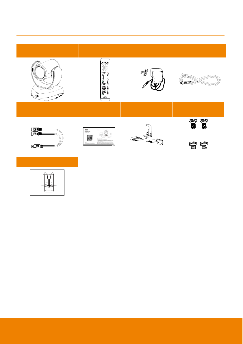
Package Contents
Camera Unit Remote Control
Power Adapter
& Power Plug*
USB 2.0 Type-B to
Type-A Cable (5m)
Mini DIN9 to Mini DIN8
RS232 Adapter Cable
QR Code Card L-Mount Brackets Screws for Mount
Drilling Paper
46.00[1.81]
Ø5.50[Ø0.22]
51.00[2.01]
P/N: 303AU340-AGR
* The power plug will vary depending on the standard power outlet of the country where it is sold.
M4 x8mm (x2)
1/4”-20 L=7.5mm (x2)
1
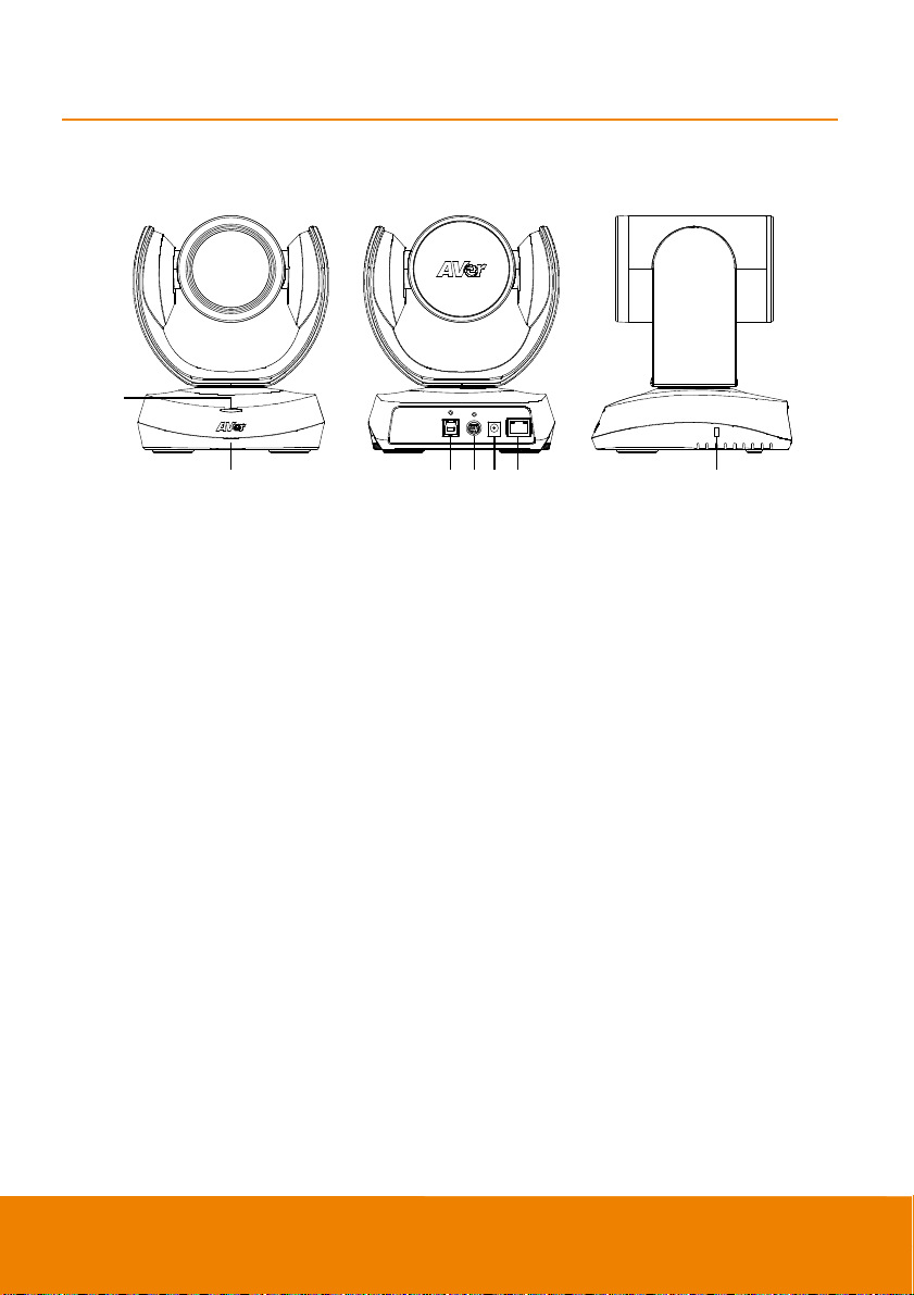
Product Introduction
Overview
1
2 3 4 5 6 7
1 Status LED 4 RS232 In/Out Port 7 Kensington Lock
2 IR Sensor 5 DC 12V Power Plug
3 USB 3.1 Type B Port 6 PoE Port*
* Power over Ethernet (PoE), compatible with IEEE 802.3AT and 802.3AF. Please use CAT 5e FTP
cable (not included.)
2
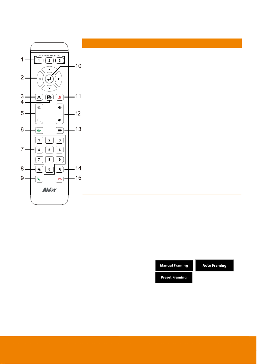
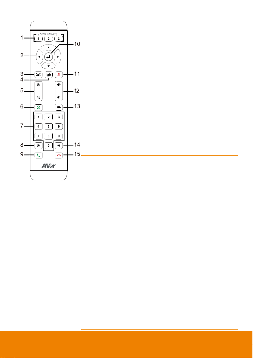
Remote Control
Name Function
1. Camera Select
2. Camera Directional
Control
3. SmartFrame
One remote can control up to 3 AVer
VC/CAM/VB series cameras. You can
use AVer PTZApp 2 to set numbers
associated with each camera, and
then select which camera you would
like to control using the remote.
[Note] If you only have one camera
and don’t need to do any setting, the
default is camera 1. If you press
camera 2 or 3 on the remote control,
you will find your remote can’t control
your camera. In this case, please
press camera 1 on your remote again.
Use the directional buttons on the
remote to control the direction of the
camera. Press the directional button to
move the camera or press and hold to
continuously pan or tilt.
One-click automatic FOV adjustment
to fit all participants.
Press for 1 second to switch the
SmartFrame function among Manual
Framing/Auto Framing/Preset Framing
modes. A message (as figures shown)
will display on the screen to indicate
the mode.
[Notes]
SmartFrame deploys face and
body detection technology. People
wearing masks and side facial
profiles can still be detected. The
maximum detection distance is
7~10 meters.
3
Camera will track people while
moving. It will start to focus and
zoom in once people stop moving
for 1~5 seconds, depending on the
framing speed you choose.
Preset Framing: Set up preset
points in advance (Only for Preset
points 1~9. Preset 0 is for home
position). Camera tracks one
presenter and shoots the preset
areas instead of focusing and
zooming into presenter.
4. OSD Menu
5. Zoom In/Out
6. Preset
7. Preset Position/Number
Buttons
To pull up OSD menu while using
HDMI out function. Not supported for
CAM520 Pro2.
Increase/Decrease the camera zoom.
The Preset button on the remote
serves 2 functions.
To Save a Preset – Move camera to
desired position. Press and hold the
preset button until you receive the
save message on the screen. Select
preset position button 0-9 to store the
current camera position. Repeat steps
if needed.
To Load a Preset - Press the preset
button and preset position button 0-9
to load a saved camera position.
Repeat steps if needed.
Preset position buttons are used in
conjunction with the Preset button to
save positions. There are a total of 10
presets.
Press the preset button first and then
press 0~9 for the camera to move to
the saved position.
[Notes]
Press and hold the number button
4
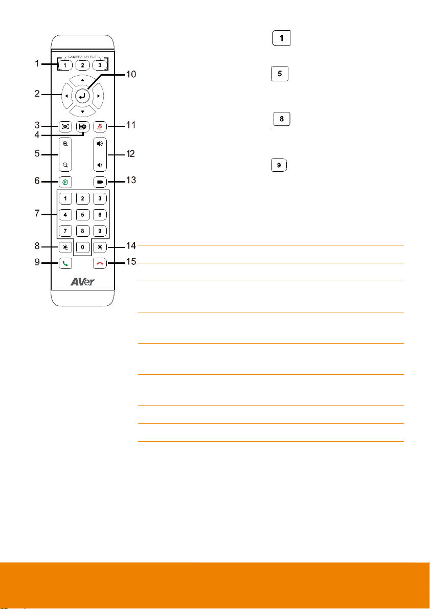
8. Brightness -
9. Call/Answer
10. Enter
11. Mute/Un-mute
Speakerphone
12. Volume Up/Down
13. Preset Hot Key
14. Brightness +
15. Hang Up
“
” for 1 second to turn on or
off the WDR function.
Press and hold the number button
“
” for 1 second to turn on or off
the SmartFrame function.
Press and hold the number button
” for 1 second to enable or
“
disable RTMP streaming function.
Press and hold the number button
“
” for 1 second to force camera
to enter sleep mode. It will cut all
the video streaming off. To wake it
up, press the button for 1 second
again or press direction button. It’s
not workable while USB streaming
is on.
Decrease the brightness.
Answer a call or start a call.
To confirm selection. Not supported for
CAM520 Pro2.
Mute/Un-mute the speakerphone. Not
supported for CAM520 Pro2.
Adjust volume up or down. Not
supported for CAM520 Pro2.
Press to move the camera to the
preset position the user has set.
Increase the brightness.
End the call.
5

Pan and Tilt Angle
90°
170°170°
30°
6
Installation
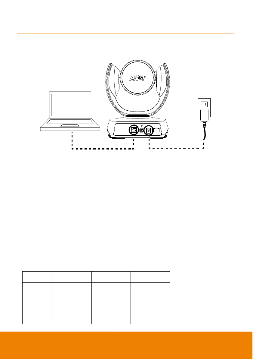
Device Connection
USB cable
1. Use USB cable to connect the CAM520 Pro2 to your PC/laptop (refer to diagram above).
2. Connect the power to the CAM520 Pro2; powerindicator will light up and camera head will rotate.
3. Install PTZApp 2 on laptop or PC that is connected with CAM520 Pro2. The app can be used to
adjust and setup the parameters of the camera (refer to the section of PTZApp 2).
4. To make a call, run your video application (Zoom, Microsoft
®
Google Meet, Intel
TrueConf, Adobe Connect, Cisco WebEx
WebRTC, Wirecast, XSplit, etc.). Select CAM520 Pro2 as your video device.
[Notes]
Use the USB 2.0 cable included in the package.
CAM520 Pro2 has the USB 3.1 port which is USB 2.0 compatible.
Maximum resolution/fps for USB 2.0 and USB 3.1 port are shown below.
USB 2.0 1080@ 60 fps 720p@ 10 fps
USB 3.1 1080@ 60 fps 1080p@ 30 fps 1080p@ 30 fps
Unite™, RingCentral, BlueJeans, V-Cube, LiveOn, CyberLink U Meeting®,
®
, Fuze, GoToMeeting™, Microsoft® Lync™, Vidyo, vMix,
M-JPEG/ fps
NV12/fps YUV/fps
720p@ 10 fps
480p@ 30 fps
480p@ 30 fps
Power cord
®
Teams, Skype for Business, Skype,
7
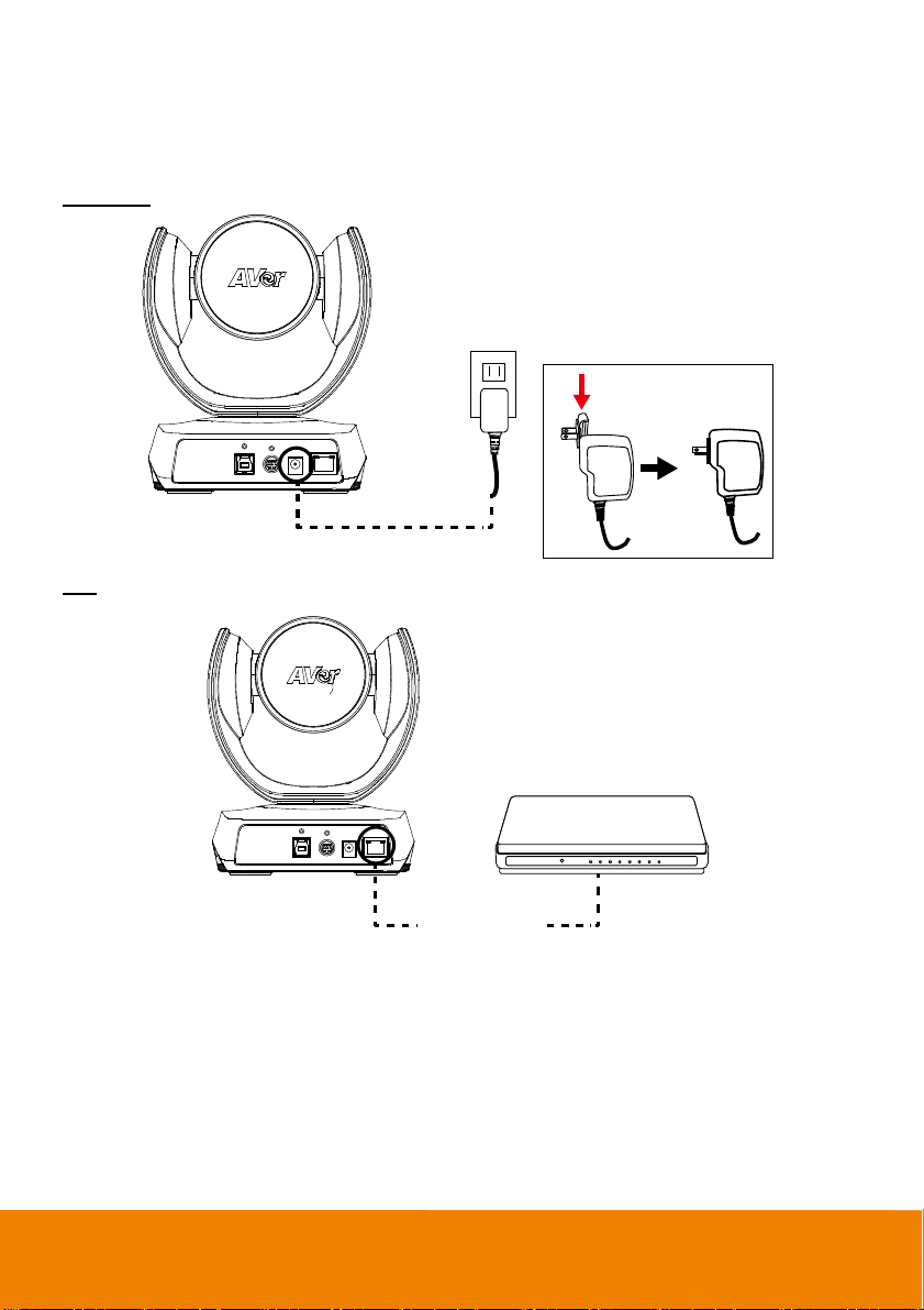
Power Connection
The power supply can be plugged into the wall outlet or drawn from PoE switch (Ethernet).
Wall outlet
Power cord
PoE
Ethernet cable
(Not included)
[Note] To ensure stability of IP video streaming, please use CAT 5e FTP cable (not included).
Switch / PoE Switch
8
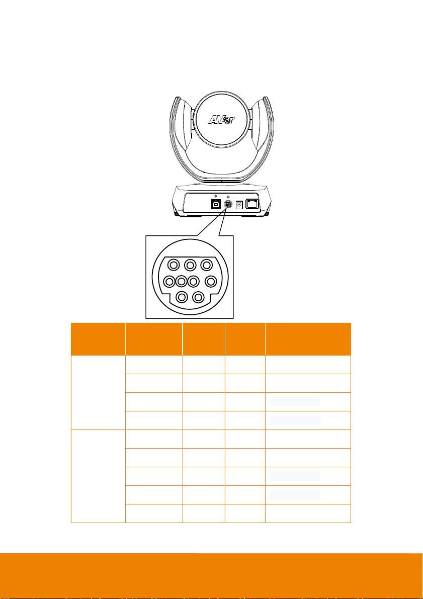
RS232 Connection
Camera RS232 Port Pin Definition
2
789
3456
1
Function
VISCA IN
VISCA OUT
Mini DIN9
PIN #
1 Output DTR Data Terminal Ready
2 Input DSR Data Set Ready
3 Output TXD Transmit Data
6 Input RXD Receiver Data
7 Output DTR Data Terminal Ready
4 Input DSR Data Set Ready
8 Output TXD Transmit Data
9 Input RXD Receiver Data
5 --- --- Not connect
I/O Type Signal Description
9
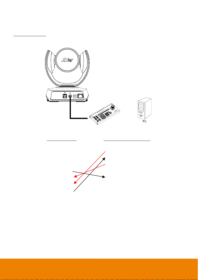
Computer/Keyboard Controller and Camera Connection
Direct Connection
If users do not use AVer RS232 adapter cable, please refer to the pin connection shown below.
Mini DIN9 to
DB9 Cable
Camera controller
Camera
(Mini DIN9)
1. DTR (IN) 1. DCD
2. DSR (IN) 2. RXD
3. TXD (IN) 3. TXD
6. RXD (IN) 4. DTR
7. DTR (OUT) 5. GND
4. DSR (OUT) 6. DSR
8. TXD (OUT) 7. RTS
9. RXD (OUT) 8. CTX
9. RI
Camera controller or PC
or
(DB9)
10

Use the supplied RS232 mini DIN9 to mini DIN8 cable
RS232 mini DIN9
to mini DIN8 cable**
VISCA in (Female)
Mini DIN8
to DB9 cable*
VISCA out (Female)
or
Camera controller
Camera controller or PC
(DB9)
Camera
(Mini DIN8)
1. DCD 1. DTR (IN)
2. RXD 2. DSR (IN)
3. TXD 3. TXD (IN)
4. DTR 4. GND (IN)
5. GND 5. RXD (IN)
6. DSR 6. GND (IN)
7. RTS
8. CTX
9. RI
1. DTR (OUT)
2. DSR (OUT)
3. TXD (OUT)
4. GND (OUT)
5. RXD (OUT)
6. GND (OUT)
11
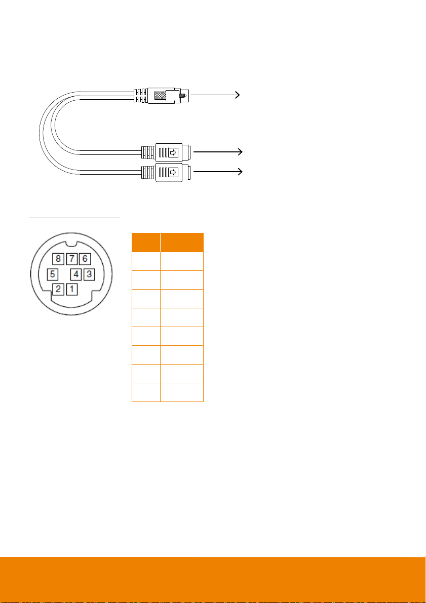
* Mini DIN8 to D-Sub9 (DB9) cable 064AOTHERBPK is an optional item.
C
** RS232 mini DIN9 to mini DIN8 Cable Pin Definition
Mini DIN9
Connect to AVer camera
Mini DIN8 (IN)
Connect to next camera
Connect to camera controller or P
Mini DIN8 Pin Definition
Mini DIN8 (OUT)
No. Pin
1 DTR
2 DSR
3 TXD
4 GND
5 RXD
6 GND
7 NC
8 NC
12
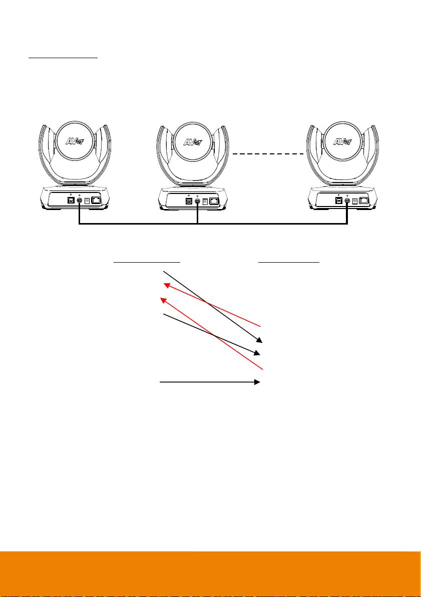
Camera Cascade Connection
Direct Connection
If users do not use AVer RS232 adapter cable, please refer to the pin connection shown below for
cascading cameras.
Total can connect up to 7 cameras.
12 7
Mini DIN9 Cable Mini DIN9 Cable Mini DIN9 Cable
Camera 1
(Mini DIN9)
1. DTR (IN) 1. DTR (IN)
2. DSR (IN) 2. DSR (IN)
3. TXD (IN) 3. TXD (IN)
6. RXD (IN) 6. RXD (IN)
7. DTR (OUT) 7. DTR (OUT)
4. DSR (OUT) 4. DSR (OUT)
8. TXD (OUT) 8. TXD (OUT)
9. RXD (OUT) 9. RXD (OUT)
SHIELD SHIELD
Camera 2
(Mini DIN9)
13
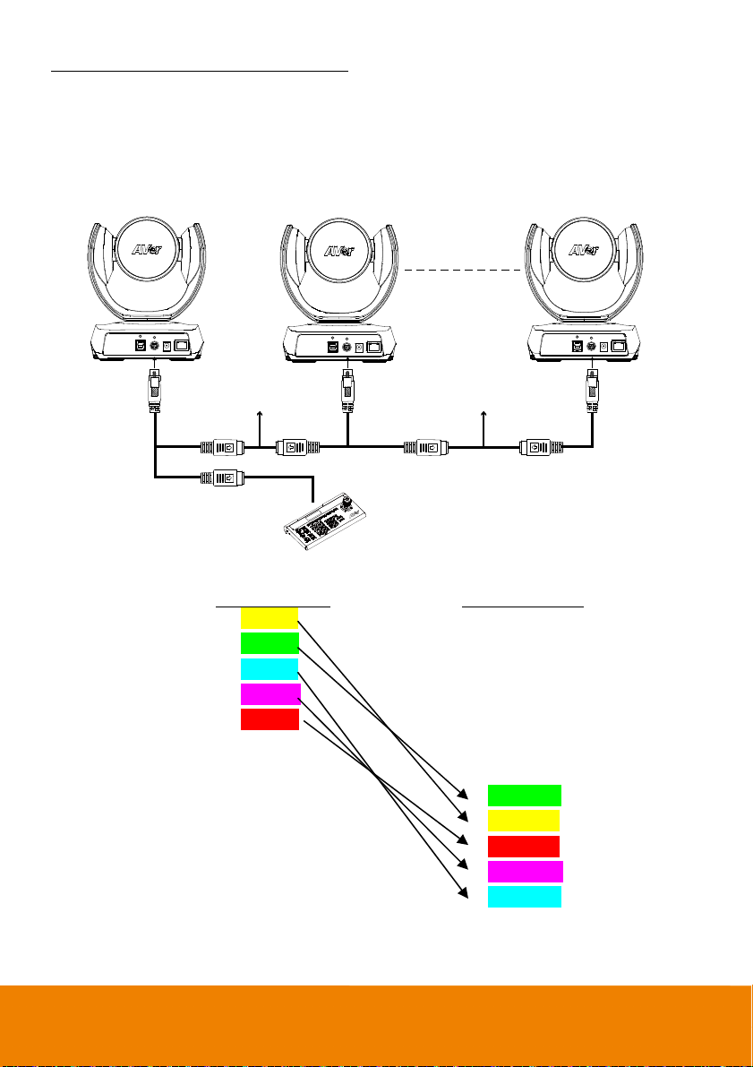
Use the RS232 mini DIN9 to mini DIN8 cable
Total can connect up to 7 cameras.
To facilitate the camera cascade, users can use AVer RS232 adapter cable.
Connect camera with AVer mini DIN9 to mini DIN8 adapter cable. Connect the mini DIN8 female side
to male mini DIN8 Visca cable (Users have to buy it in the market) and then connect AVer mini DIN9 to
mini DIN8 adapter cable again to connect to next camera.
12 7
RS232 mini DIN9
to mini DIN8 cable
RS232 mini DIN9
to mini DIN8 cable
Mini DIN8 cable (Male)
VISCA in (Female)
VISCA out (Female)
VISCA out (Female)
Camera controller
Camera 1
Mini DIN8 cable (Male)
VISCA in (Female)
Camera 2
(Mini DIN8)
1. DTR (IN) 1. DTR (IN)
2. DSR (IN) 2. DST (IN)
3. TXD (IN) 3. TXD (IN)
4. GND (IN) 4. GND (IN)
5. RXD (IN) 5. RXD (IN)
6. GND (IN) 6. GND (IN)
1. DTR (OUT)
2. DSR (OUT)
3. TXD (OUT)
4. GND (OUT)
5. RXD (OUT)
6. GND (OUT) 6. GND (OUT)
VISCA out (Female)
(Mini DIN8)
1. DTR (OUT)
2. DST (OUT)
3. TXD (OUT)
4. GND (OUT)
5. RXD (OUT)
RS232 mini DIN9
to mini DIN8 cable
14
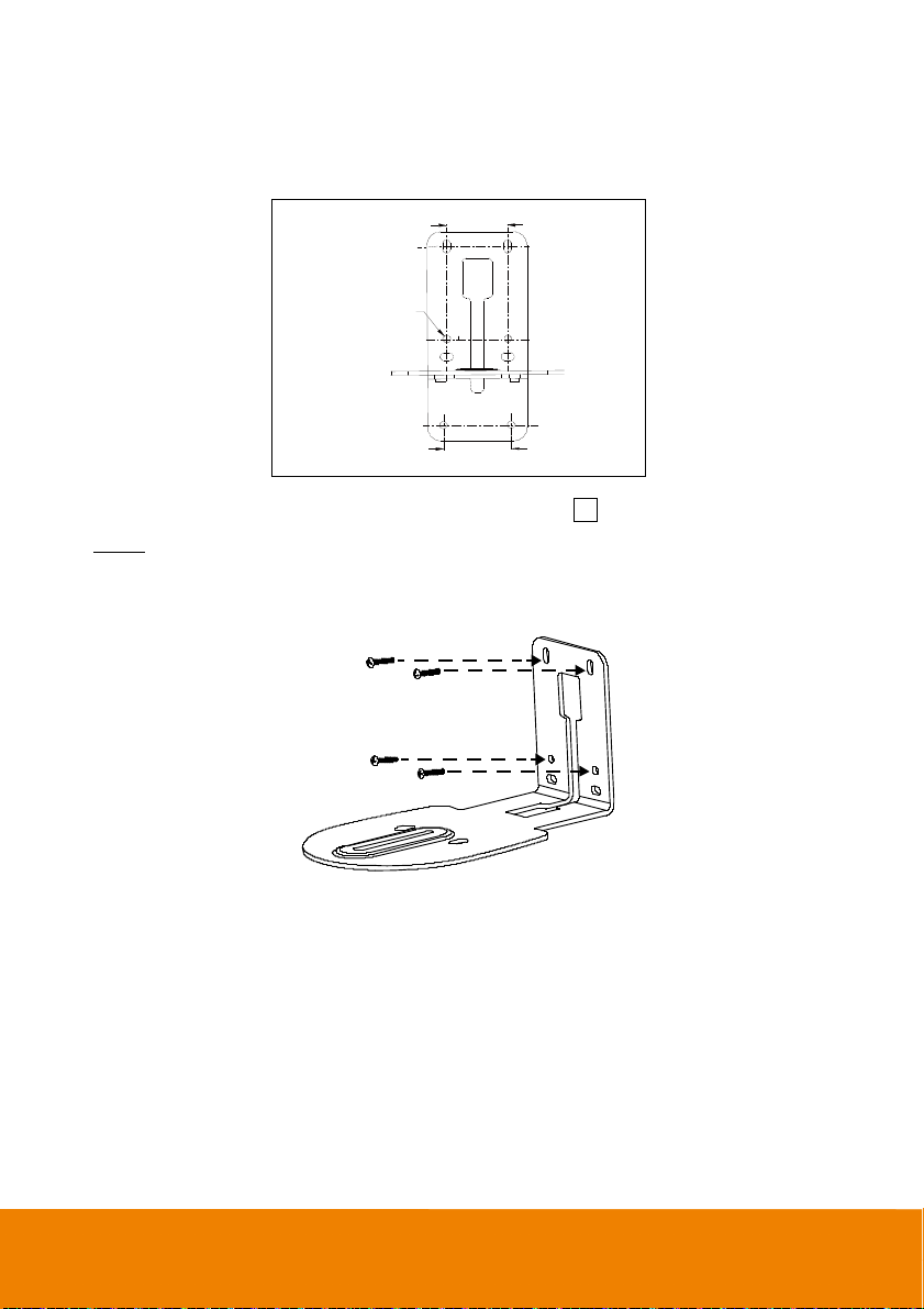
Wall Mount Installation
1. Use the drilling paper included in the package to drill the holes in the wall where the user wants to
mount the camera.
46.00[1.81]
Ø5.50[Ø0.22]
P/N: 303AU 340-AGR
2. Use the screws (not included) to secure the L-mount bracket
Screw
For Cement wall:
For Wooden wall:
M4 x20mm self-tapping screws (x4) + Plastic conical anchor
M4 x20mm self-tapping screws (x4)
51.00[2.01]
on the wall.
A
15
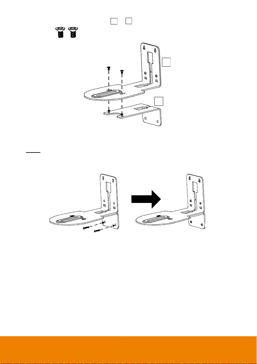
3. Then, assemble the L-mount brackets A + B with screws (included in package).
Screw size:
M4 x8mm (x2)
A
B
4. After assembling the L-mount brackets, use the screws (not included) to secure the lower part of
L-mount brackets on the wall.
Screw
For Cement wall:
For Wooden wall:
M4 x20mm self-tapping screws (x2) + Plastic conical anchor
M4 x20mm self-tapping screws (x2)
16
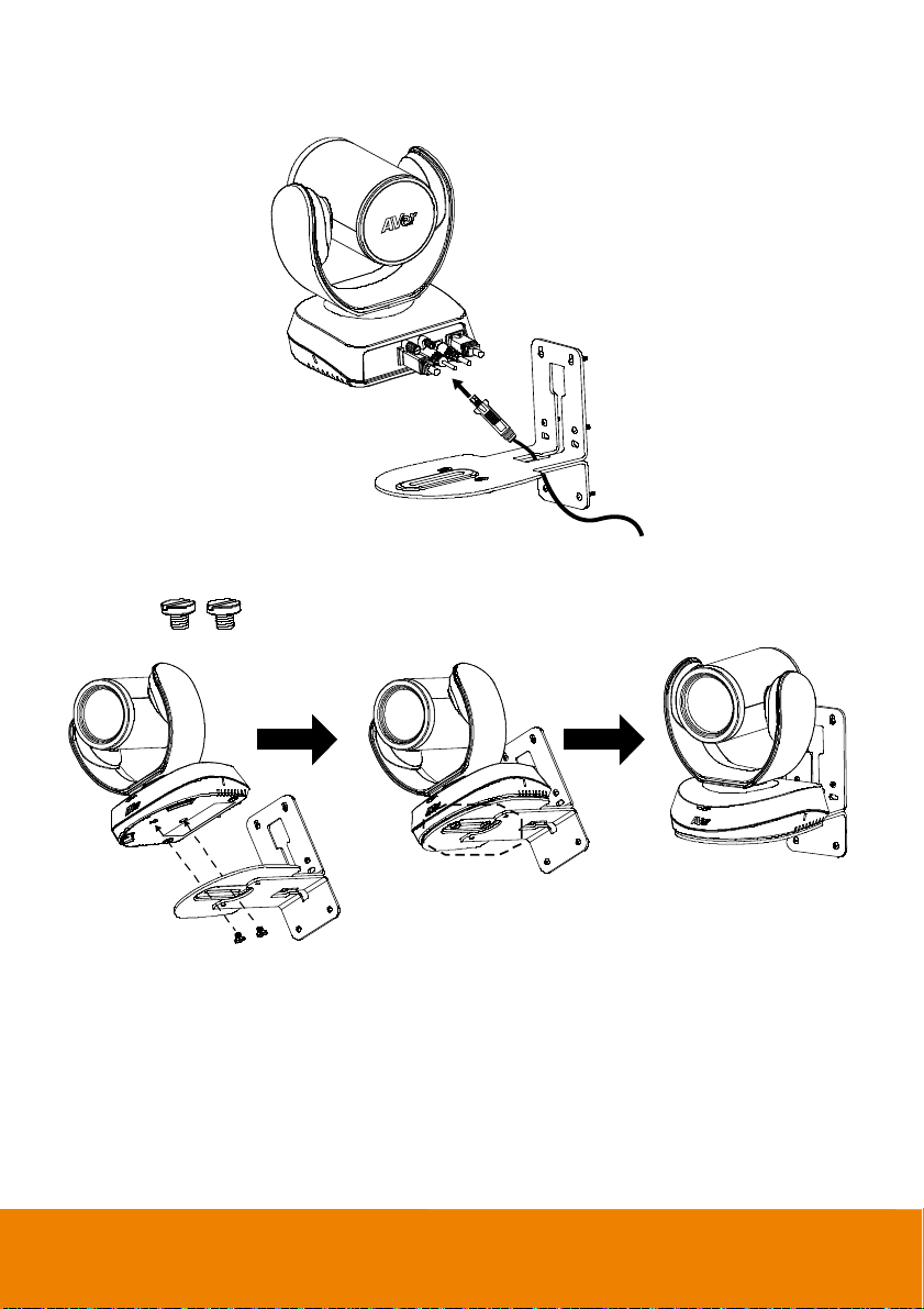
5. Pass the cables through the hole on the L-mount bracket and connect the cables to corresponding
connection ports.
6. Use the remaining screws (included in package) to secure the camera on the L-mount bracket.
Screw:
1/4”-20 L=7.5mm (x2)
17

Ceiling Mount Installation (Optional)
1. Install the provided screw underneath the camera but do not tighten.
2. Turn the camera to right side.
18

3. Pass cables through A or B hole first. Connect cables with camera.
4. Turn the camera to face the front side. Install the second screw and tighten both screws.
19

5. Find suitable screws to fix the camera mount to the ceiling.
20

Secure the Cables
The USB and RS232 cables have a screw on the cable for securing cable on the camera.
Install the cable first and tighten the screw to secure the cable.
[Note] Make sure the cable is well connected to the connector on the camera before securing the
cable.
21

Operating the Camera
Make a Video Call
1. Make sure all devices (CAM520 Pro2, laptop/PC, TV/monitor) are well connected and powered
on.
2. Run your video application (Zoom, Microsoft
®
Intel
Unite™, RingCentral, BlueJeans, V-Cube, LiveOn, CyberLink U Meeting®, TrueConf,
Adobe Connect, Cisco WebEx
Wirecast, XSplit, etc.) on your PC or laptop.
3. Set the CAM520 Pro2 camera as the primary camera for your video application (refer to your
video application user guide). You can now make your call.
[Note] The CAM520 Pro2 is a plug-and-play conference camera. The system requires no special
drivers, but we do recommend installing the PTZApp 2 for a better user experience. For information on
how to install and use the PTZApp 2, refer to the PTZApp 2 section in this user manual.
®
, Fuze, GoToMeeting™, Microsoft® Lync™, Vidyo, vMix, WebRTC,
Make a Connection through the Browser
CAM520 Pro2 has an Ethernet port for IP streaming and allows administrators to remotely control and
set up the camera via an internet access. Moreover, CAM520 Pro2 also supports RTSP and RTMP
functions. For more details, please contact our technical support.
1. Make sure the CAM520 Pro2 has an internet access connection.
®
Teams, Skype for Business, Skype, Google Meet,
2. Launch PTZApp 2* ( ) and connect CAM520 Pro2 to PC with USB cable. The camera default
IP address is 192.168.1.168.
[Note] The browser supports:
Chrome: version 76.x or above Firefox: version 69 or above IE: Doesn’t support
22

3. Click pencil icon ( ) to edit IP address**.
4. Click weblink icon ( )to launch Chrome page. Please enter the password (default password is
aver4321). User will be asked to set a new account and password. (Please enter PTZApp2 to
reset password back to default while password is forgotten.)
5. After editing IP address, user can access web settings of the camera with only Ethernet cable
connection. Unplug the USB cable.
23

6. The main web screen is displayed as below.
* For information on how to install and use the PTZApp 2, refer to the PTZApp 2 section in this user
manual.
** To support IP address changes in groups, user can download AVer IP Finder app.
1. Download the IP Finder from https://www.aver.com/download-center (Global & European
Headquarters) or https://www.averusa.com/business/support/ (USA).
2. Run the IP Finder.
3. Click “Search”, and all available devices will be listed on the screen.
4. Select a camera from the list. The corresponding fields of IP address will display.
5. To change the IP address of camera, user can select “DHCP” or “Static IP”.
The DHCP should get the IP address from local dynamic IP sever. The static IP, user can enter the
specific IP address. Click “Apply” to apply the setting to the camera. The password is required
(default password is aver4321).
6. Click “Search” button to re-scan the camera.
7. Double-click on the IP address of camera from the list can connect to camera through the browser.
8. Enter the default password (aver4321) to login to Web setup screen.
24

25 26

Web Settings
CAM520 Pro2 supports Ethernet connection; users can enter the IP address into the web browser to
connect to the camera for detail settings.
First Time Login
To find the IP address of the camera, please refer to “Make a connection through the Browser”
section.
1. Open the browser on your laptop/PC and enter the IP address of the camera.
2. Enter the password at login screen. The default password is “aver4321”.
3. The main web screen is displayed.

Live Screen Operation
User can control the camera direction, zoom in/out, and preset selection.
[Notes]
1. The system will force the first login to log out when there is a second login.
If the web page is idle without any request for more than 4 hours, user will be log out.
2. The resolution of live screen is 480p/5fps.
Functions list Preset selection
Preset position
name column
Live screen
Logout the
Web interface
Preset setups, directional buttons,
manual SmartFrame button, and
zoom in/out
One Shot focus
27

Set up the Preset
User can set 10 preset positions.
1. In live screen, use mouse to scroll up or down and click the preset number frame (0~9).
2. Use ▲, ▼, , and zoom in/out buttons to adjust the camera screen view to desired position.
3. Select “
Set Preset
display in preset number frame.
” button to save the preset. The system will capture the preset screen view and
28

4. Select icon to edit name of preset frame. Click other Web interface to save the name edited.
Enter name of
preset positon
5. To set another preset, repeat the above steps.
29

Select the Preset Position
Preset positions need to be set.
Use mouse to scroll up or down to select the preset. Select the preset user wants. The live screen will
move to the preset screen view.
30

Camera Settings
The video icon is to turn on camera live view while doing any settings.
Press the icon to show people count number.
Press the icon to show the time interval of enabling
the live streaming of the camera.
IP icon shows the IP address of the camera.
Live screen preview
Press X button to turn off live view.
31

Tracking Mode
Select Setting > Camera > Tracking Mode > Off, Manual Frame, Auto Frame, or Preset Framing.
Off: Tracking mode is disabled.
Manual Frame: User one-click SmartFrame button and camera will adjust view angle to fit all
participants in screen.
Auto Frame: Camera automatically adjusts view angle to frame all participants on screen every
time when it detects participants’ faces or bodies. This action will be activated once people in the
room sit or stand still for 1~5 seconds, depending on the framing speed you select. Once all the
participants are in frame, the camera will keep the image stable by not completing any action until
subjects move in or out of the screen. When a participant touch the sides of the screen, it will
trigger the camera and automatically track, detect, and frame all the participants again.
Preset Framing: Set up preset points in advance. (Only for Preset points 1~9. Preset 0 is for
home position). This is designed for requiring a specific zooming area with preferred image
proportion. Camera tracks and frames all the participants in the screen if none of them touch any
preset area. When any of them touch a preset area, the camera will immediately
zones instead of focusing and zooming into presenter. To keep the screen stable, whenever there
shoot the preset
32

is a person in the area, the camera won’t move any more until no one shows up. However, the
camera can detect the direction where the last person goes. If the person goes to the next preset
area with overlap section, the camera will directly move to the next preset area. Thus, to ensure
smooth transition, please set up zones with overlapping presets.
If the preset zones do not overlap and when the last person leave the preset area, camera will
zoom out to wide to find people and frame them again.
If more than 2 presets areas are touched by 2 persons, camera will go to preset 1. The priority is
preset 1>preset2> preset 3….>preset 9
Overlap beginning & end of each zone
CAM520 Pro2 frames people in masks or any facial profile up to 7~10 meters away!
[Note]
33

Framing Speed
Select Setting > Camera > Framing Speed > Slow Speed, Middle Speed, or High Speed (default).
When in auto framing or preset framing mode, camera will automatically frame people if they stand still
without moving for 1~5 seconds.
Slow Speed: camera starts to frame people if they don’t move for 5 seconds.
Middle Speed: camera starts to frame people if they don’t move for 3 seconds.
High Speed: camera starts to frame people if they don’t move for 1 second.
34

Smart Frame Preset Point
Select Setting > Camera > Smart Frame Preset Point > Default(Center of the screen) or Preset0 ~
Preset9.
The default is the central of the image screen. Choose a preset point so that camera can detect
participants from the wide view of the assigned preset area direction.
35

Auto Focus
Set auto focus mode.
First select Setting > Camera > Camera Focus > Auto.
Select Setting > Camera > Auto Focus > PTZ or Continuous.
PTZ: Click the button (such as pan, tilt, or zoom in/out) to adjust focus once.
Continuous: The camera will adjust the focus when the objects have moved.
36

Camera Focus
Set auto/manual focus mode.
Select Setting > Camera > Camera Focus > Auto or Manual.
Auto: Camera adjusts focus automatically.
Manual: You can adjust the camera focus by moving the control bar below.
Home Position
Every time when powering on the camera, it will turn to this position.
Select Setting > Camera > Home Position > Last Operation Position, Factory Center Position, or
Preset 0.
37

Sleep Position
When the camera idles for certain period, it will enter sleep mode and go to the sleep position. Please
set up sleep timer to enable sleep mode.
Select Setting > Camera > Sleep Position > Factory Downside Position or Preset 9.
Sleep Timer
Set the camera idle time to enter sleep mode.
Select Setting > Camera > Sleep Timer > Off, 10 sec, 5 min, 10 min, or 20 min.
Please notice that whenever there is USB streaming or RTSP/RTMP streaming, the camera won’t
enter sleep mode.
38

On Screen Menu
Enable/disable on screen display status information. For instance, when it is at auto frame mode, it will
appear “Auto framing” on the bottom of the screen. If you don’t want to see the words, please select
Off.
Select Setting > Camera > On Screen Menu > Off, On, or Load Preset Off.
Camera Binding
With multiple cameras connection, users can set each camera to buttons 1 to 3 on the remote control.
Select Setting > Camera > Camera Binding > Camera1, Camera2, or Camera3.
39

Save Preset
Enable/disable “save preset” function. When applicable, IT personnel can limit end-user access to
change preset points by locking “save preset” function and switching this function off.
When off, user can’t save preset points via IR remote, Hot key, VISCA, and webpage.
Select Setting > Camera > Save Preset > Off or On.
40

ImageSettings
Image Flip
If the CAM520 Pro2 is installed in the upside down position, please enable the "Flip".
Select Setting > Image > Image Flip > Off or On.
Image Mirror
To mirror the camera image.
Select Setting > Image > Image Mirror > Off or On.
41

True WDR
In back light environment, enable WDR to improve the brightness of image.
Select Setting > Image > Tru e WD R > Off or On.
The frame rate will be limited to 30fps while WDR is on.
If user enables this function in a normal light condition, the image will become over exposure and
encounter image blur.
Frequency
Select the frequency of the camera.
Select Setting > Image > Frequency > 50 HZ or 60 HZ.
42

White Balance
Select the white balance setting for various light conditions or color temperature.
Select Setting > Image > White Balance > Auto or Manual.
Noise Reduction
To reduce the noise from the signal.
Select Setting > Image > Noise Reduction > Off, Low, Middle, or High.
43

Brightness
Adjust the value of brightness.
Select Setting > Image > Brightness > 1 ~ 9.
Sharpness
Adjust the value of sharpness.
Select Setting > Image > Sharpness > Off, Low, Middle, or High.
44

Saturation
Adjust the value of saturation.
Select Setting > Image > Saturation > 1 ~ 9.
Low Light Compensation
Select Setting > Image > Low Light Compensation > Off or On.
Please notice that the frame rate will drop to 10~15 fps.
45

RS232 Setting
When CAM520 Pro2 connects with PTZ camera controller through the RS232 port, please setup
ADDR, Baud Rate, Protocol, and Visca Over IP settings.
Select Setting > RS232.
46

Video Format Settings
H.264 Profile
While in live broadcasting, user can choose preferable profile to get best streaming quality.
Select Video Format > H.264 Profile > Baseline Profile or High Profile.
47

IP Stream Resolution
Set up the resolution for IP stream. Not supported for USB video stream.
Select Video Format > IP Stream Resolution only (not for adjusting USB video stream) > 1080P,
720P, 480P, or 360P.
Please notice that if USB streaming (VC software side) is already in use at 1080p/30fps, the IP
streaming resolution (RTSP) will be limited to 720p/30fps. It’s better to disconnect USB streaming
while having RTSP/ RTMP IP streaming to ensure the video transmission quality.
48

Frame Rate
Set up the frame rate value.
Select Video Format > Frame Rate > 60 FPS, 30 FPS, or 15 FPS.
Bit Rate
Set up the bit rate value.
Select Video Format > Bit Rate > Auto, 512 Kbps, 1 Mbps, 2 Mbps, 4 Mbps, 8 Mbps, 16 Mbps, or
32 Mbps.
For Facebook live broadcasting, it’s suggested to choose less than 4Mbps to ensure smooth
streaming.
49

RTSP
To use RTSP player connecting to the camera, please enter the RTSP URL which displays on the web
in your application such as VLC, PotPlayer, or Quick Time.
Select On to enable RTSP function.
50

Change RTSP Password
1. Select Video Format > RTSP > Set RTSP Access Password.
2. Enter the new password.
3. Select Change to save the new password.
51

RTMP
Set up for uploading the camera’s live view to the broadcasting platform (e.g. YouTube).
Select Video Format > RTMP.
1. Locate the RTMP server URL and stream key from the broadcasting platform and enter in Server
URL and Stream Key fields.
2. Select Start to begin uploading the live video of the camera to the broadcasting platform.
3. Select Stop to stop uploading the video.
52

Network Settings
DHCP
Enable/disable DHCP function.
Select Network > DHCP > Off or On.
Static IP
Assign a fixed IP address to the camera. Please turn off the DHCP function.
1. Select Network > Static IP.
2. Click pencil icon and enter the IP Address, Gateway, NetMask, and DNS in the corresponding
fields.
53

System Settings
Language
Select the language of the system.
Select System > Language > English, Traditional Chinese, or Japanese.
54

Firmware Update
Update the camera’s firmware.
Select System > FW Update > Auto Update or Manual Update.
Auto Update: The system will check firmware version from AVer server and request to update.
Manual Update: To update the firmware from specific location.
After updating, the camera will reboot and the connection will be lost. Please wait for few minutes and
always keep the power cable connected. If unplugging the power during this process, it will cause
damage of the device.
55

Factory Default
Reset the camera back to factory default setting.
1. Select System > Factory Default > Reset.
2. User can choose to keep current IP address or back to default.
3. Select Continue to reset back to factory default.
[Note] When factory default is activated, the password of Webpage login will not be set to default. For
security concerns, to reset password of webpage access, please download PTZApp 2 to reset it.
56

Camera Reboot
Restart the camera manually.
1. Select System > Camera Reboot > Reboot.
2. Select Continue to reboot the camera.
57

Change Password
Change the web login password. The default password is “aver4321”.
1. Select System > Change Password > Change WEB Access Password.
2. Enter the old account and password. Select Continue.
3. Enter the new account and password. Select Continue to save the new setting.
4. If users forget the password and want to revert back to the default password, please use PTZApp
2 to reset it.
58

SSL Certificate
Import the SSL certificate from specific location.
1. Select System > SSL Certificate > Import.
2. Select the type by clicking “+”.
3. Direct the file location.
4. Select Import.
59

Date Format
Select the date format.
Select System > Date Format > yyyy-mm-dd, mm-dd-yyyy, or dd-mm-yyyy.
Time Format
Set up the time format.
Select System > Time Format > 24-Hour or 12-Hour.
60

Time Correction Mode
Adjust time automatically or manually.
Select System > Time Correction Mode > Auto or Manual.
Auto: The system time will be set by NTP server on the network. Click the pencil icon of NTP
Server and enter the IP address of NTP server. Select the Time Zone. Select NTP Update to save
setting. Select Activate to start auto time adjustment.
[Note] Our default NTP server is located in the USA. If this does not work in your country,
please manually key in the desired NTP server.
61

Manual: User can set up time manually. Click the pencil icon and enter the Year, Month, Day,
Hour, and Minute. Select Confirm to save the settings.
62

Information
Display the information of Model Name, Firmware Version, Serial Number, IP Address, and MAC
Address.
Select System > Information.
63

PTZApp 2
In PTZApp 2, user can change the IP address setting of CAM520 Pro2, configure the parameters of
the camera, set up AI tracking functions and some advanced image settings, pan, tilt, and zoom the
camera.
Install PTZApp 2
Please go to https://www.aver.com/download-center (Global & European Headquarters) or
https://www.averusa.com/business/support/ (USA) to download the PTZApp 2. After downloading,
double-click on the file and follow the on-screen instructions to complete the installation.
After installing the PTZApp 2, double-click on the PTZApp 2 icon to run the application.
Use PTZApp 2 with USB Devices
1. Run your video application and make a video call.
2. During your video call, you can use the PTZApp 2 to pan, tilt and zoom the camera in/out and
enable/disable the true WDR, brightness, and sharpness feature.
3. Launch PTZApp 2 (
4. Choose “USB device” and connect CAM520 Pro2 to PC/laptop with USB cable
camera is detected, the product card will show up.
) and it will open in Chrome browser automatically.
64
. When the

5. Set up IP address. The camera default IP address is 192.168.1.168. Click pencil icon ( ) to
edit IP address.
6. Click the setting icon to change Language, Hotkey Control, and Software Version.
65

Language: Select desired language and click the check icon to confirm the selection.
Hotkey Control: User can control the camera by using keyboard. This is a general list for all AVer
USB Cameras. Backlight control equals to WDR function in CAM520 Pro2.
Software Version: Get current PTZApp 2’s version number and do auto update here.
66

7. Information: Click the drop-down triangle icon to review the information of camera. To minimize
the information, click the triangle or the bottom area of the information icon.
67

8. Camera: Click the camera icon to view the camera live view. IP address is displayed as well.
Click the X icon to close the camera live view. If the live video did not appear, please check the
camera and the laptop/PC connection to make sure all are correct and well connected.
The resolution of this small live view is 640x480 resolutions.
68

Full Screen: PTZApp 2 can switch to full screen mode. Click “ ” icon and video screen
will switch to full screen mode. In full screen mode, user can use direction panel to control
camera direction. Click “
The resolution of full screen mode is 1080p.
” icon to go back to normal screen view.
69

People Count and Stream Interval: Click the icon to show people count number and
stream interval. Click the
or icon to hide the stream interval.
Control Panel: To control the camera direction, zoom in and out, and to enable/disable the
“Smart Framing” during your video call.
70

9. Setting: Click “Setting” button to setup parameters of the camera and speakerphone. Click
arrow icon to leave the Setting page.
PTZ Control: Use control panel to setup preset positions. Since most of operations are the
same as web page, refer to Setup the Preset section (pages 28~29) for detailed setup.
Setting: To setup parameters of the camera. Since most of operations are the same as web
page, refer to Camera Settings section (pages 31~39) for detailed setup.
System: To setup system. Since most of operations are the same as web page, refer to
System Settings section (pages 53~62) for detailed setup.
71

10. PTZApp 2 Quit & Restore: To quit the application, right-click the icon on the system tray and
select “Quit”. If you can’t launch PTZApp 2 right after installation, please right –click the icon and
choose “Restore”.
72

Use PTZApp 2 with a Virtual Stream
With this function, you can have a virtual meeting with only Ethernet connection and get rid of USB
cable connection. Make sure the camera is connected with Ethernet and under the same subnetwork
as the meeting room PC (e.g. NUC).
1. Launch PTZApp2 (
2. When the camera card appears, click Start to enable the Virtual Stream function.
) on a PC and click Virtual Stream.
73

3. Virtual Stream technology uses an RTSP stream. If you set a password for RTSP, you will be
asked to provide that password while enabling this function.
4. Launch VC software (e.g. Zoom, Teams, Skype) and choose AVer USB VCam as the video
source to start collaborating.
5. While using the Virtual Stream function, you cannot change any camera settings. To pan/tilt or
zoom in/out the camera, use a remote control or VISCA control.
6. Click Stop and Home to stop using this function.
[Notes]
1. This technology only transmits video, not audio sources.
2. Video latency may vary depending on CPU power (i5 or higher is recommended).
74

EZLive
Please go to http://www.aver.com/download-center to download the AVer EZLive software. After
downloading, double-click on the file and follow the on-screen instructions to complete the installation.
Use AVer EZLive
During a video call, EZLive can help user to do:
(1) Camera ePTZ
(2) Volume control for the speaker connected
(3) Capture camera’s still images
(4) Record video
(5) Live stream to Youtube, Livehouse.in, USTREAM…etc.
(6) Camera Zoom in/out
(7) Capture PC screen shot
(8) Record PC screen video
(9) Set up livestream
(10) Open file management to retrieve photos and video files
(11) Livestream setting
(12) Drawing tool
(2)
(3)
(7) (8) (9)
75
(10)
(11)
(1)
(6)
(4) (5)
(12)
 Loading...