

Avdel nG2S 71401 Instruction Manual

Hydro-Pneumatic Power Tool
Genesis
®
Instruction Manual


3
Contents
Safety Rules 4
Specifications
Tool Specifications 5
Tool Dimensions 5
Intent of Use
Range of Fasteners 6
Part Numbering 6
Putting into Service
Air Supply 7
Operating Procedure 7
Nose Assemblies
Fitting Instructions 8
Servicing Instructions 8
Nose Tips 9
Type 1 9
Avseal®II 10
Fitting Types 2/3 or Nose Extension 11
Type 2 and Type 3 12
Accessories
Stem Deflector 13
Preparing the Base Tool for use with Stem Deflector 13
Extension 13
Swivel Heads 14
Straight Swivel Head Capability 14
Preparing the Base Tool for Right-Angle and Straight
Swivel Head Attachment 15
Straight and Right-Angle Heads 16
Fitting Instructions 16
Servicing Instructions 17
Constant Components 17
Servicing the Tool
Daily 18
Weekly 18
MolyLithium Grease EP 3753 Safety Data 18
MolyKote®55m Grease Safety Data 19
MolyKote®111 Grease Safety Data 19
Service Kit 07900-00716 20
Maintenance 20
Annually 20
Nose Equipment 20
Head Assembly 21
Rotary Valve 22
Trigger 22
Stop Plate Assembly (71213-03900) 23
Intensifier 24
General Assembly and Parts List
General Assembly of Pistol 71401-02000 (s) 26
Parts List for 71401-02000 (s) 27
General Assembly of Intensifier 71421-02000 (s) 28
Parts List for 71421-02000 (s) 29
Priming
Oil Details 30
Hyspin®VG 32 Oil Safety Data 30
Priming Procedure 31
Fault Diagnosis
Symptom, Possible Cause and Remedy 32
LIMITED WARRANTY
Avdel makes the limited warranty that it’s products will be free of defects in workmanship and materials
which occur under normal operating conditions. This Limited Warranty is contingent upon: (1) the product
being installed, maintained and operated in accordance with product literature and instructions, and (2)
confirmation by Avdel of such defect, upon inspection and testing. Avdel makes the foregoing limited
warranty for a period of twelve (12) months following Avdel’s delivery of the product to the direct purchaser
from Avdel. In the event of any breach of the foregoing warranty, the sole remedy shall be to return the
defective Goods for replacement or refund for the purchase price at Avdel’s option. THE FOREGOING
EXPRESS LIMITED WARRANTY AND REMEDY ARE EXCLUSIVE AND ARE IN LIEU OF ALL OTHER WARRANTIES
AND REMEDIES. ANY IMPLIED WARRANTY AS TO QUALITY, FITNESS FOR PURPOSE, OR MERCHANTABILITY
ARE HEREBY SPECIFICALLY DISCLAIMED AND EXCLUDED BY AVDEL.
Avdel UK Limited policy is one of continuous product development and improvement and we reserve the right to change the specification of any product without prior notice.

4
Safety Rules
This instruction manual must be read with particular attention to the following safety rules, by any person
installing, operating, or servicing this tool.
1 Do not use outside the design intent.
2 Do not use equipment with this tool/machine other than that recommended and supplied by Avdel UK Limited.
3 Any modification undertaken by the customer to the tool/machine, nose assemblies, accessories or any equipment supplied by
Avdel UK Limited or their representatives, shall be the customer’s entire responsibility. Avdel UK Limited will be pleased to advise
upon any proposed modification.
4 The tool/machine must be maintained in a safe working condition at all times and examined at regular intervals for damage and
function by trained competent personnel. Any dismantling procedure shall be undertaken only by personnel trained in Avdel UK
Limited procedures. Do not dismantle this tool/machine without prior reference to the maintenance instructions. Please contact
Avdel UK Limited with your training requirements.
5 The tool/machine shall at all times be operated in accordance with relevant Health and Safety legislation. In the U.K. the “Health
and Safety at Work etc. Act 1974” applies. Any question regarding the correct operation of the tool/machine and operator safety
should be directed to Avdel UK Limited.
6 The precautions to be observed when using this tool/machine must be explained by the customer to all operators.
7 Always disconnect the air line from the tool/machine inlet before attempting to adjust, fit or remove a nose assembly.
8 Do not operate a tool/machine that is directed towards any person(s) or the operator.
9 Always adopt a firm footing or a stable position before operating the tool/machine.
10 Ensure that vent holes do not become blocked or covered.
11 The operating pressure shall not exceed 7 bar.
12 Do not operate the tool if it is not fitted with a complete nose assembly or swivel head unless specifically instructed otherwise.
13 Care shall be taken to ensure that spent stems are not allowed to create a hazard.
14 Vacuum Air MUST be turned off using the Trigger before removing the Stem Collector Bottle which Must be emptied when half full.
15 The Tool MUST NOT be operated with the Stem Collector Bottle removed.
16 If the tool is fitted with a stem deflector, it should be rotated until the aperture is facing away from the operator and other person(s)
working in the vicinity.
17 When using the tool, the wearing of safety glasses is required both by the operator and others in the vicinity to protect against
fastener ejection, should a fastener be placed ‘in air’. We recommend wearing gloves if there are sharp edges or corners on the
application.
18 Take care to avoid entanglement of loose clothes, ties, long hair, cleaning rags etc. in the moving parts of the tool which should be
kept dry and clean for best possible grip.
19 When carrying the tool from place to place keep hands away from the trigger/lever to avoid inadvertent start up.
20 Excessive contact with hydraulic fluid oil should be avoided. To minimize the possibility of rashes, care should be taken to wash
thoroughly.
21 C.O.S.H.H. data for all hydraulic oils and lubricants is available on request from your tool supplier.
Specifications
5
Air Pressure Minimum - Maximum 5-7 bar
Free Air Volume Required @ 5.5 bar 3.6 litres
Stroke Minimum 17 mm
Pull Force @ 5.5 bar 10.88 kN
Cycle time Approximately 1 second
Noise Level 75 dB(A)
Weight Without nose equipment or intensifier 0.88 kg
Vibration Less than 2.5 m/s
2
Intensifier Ratio 44:1
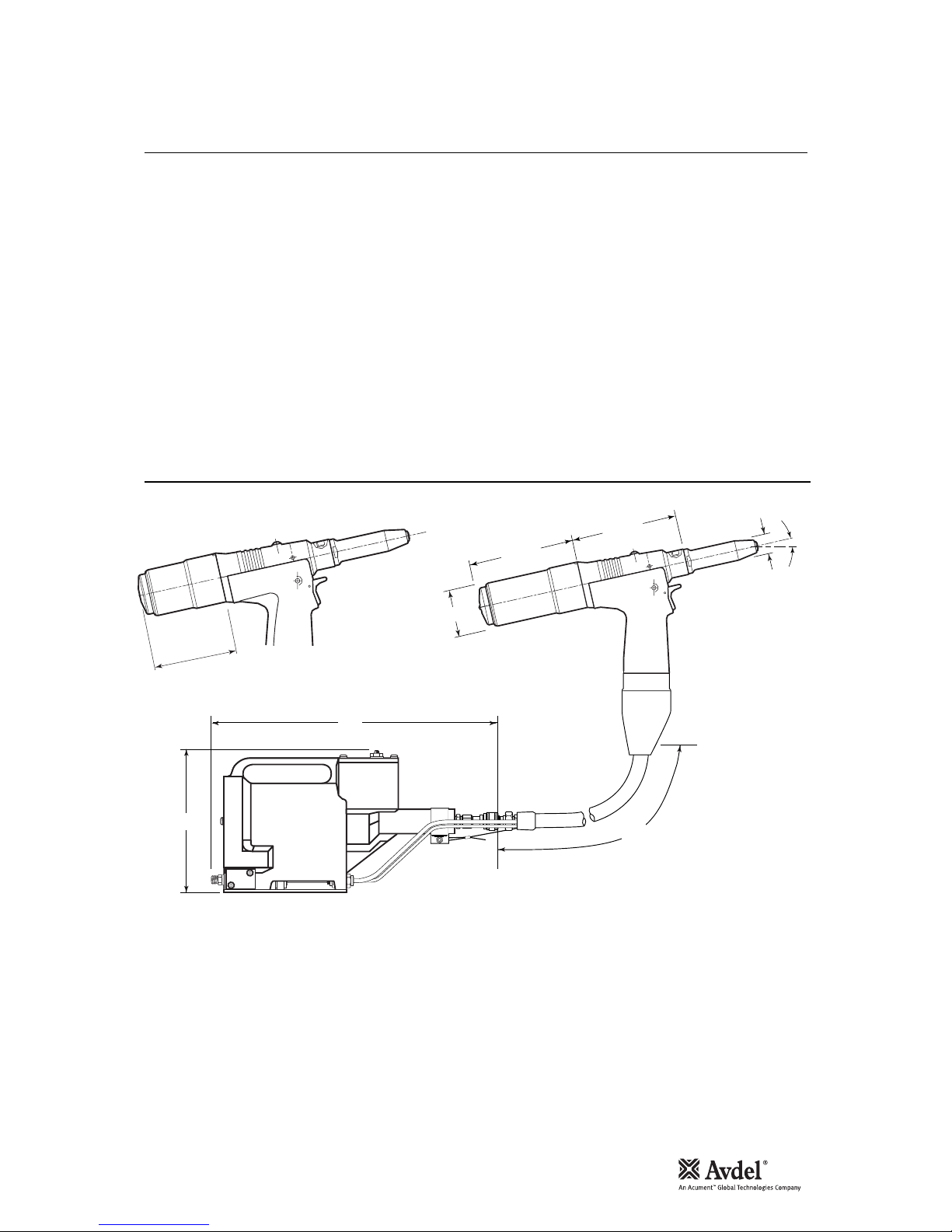
Dimensions in millimetres
Tool Dimensions
200
417
12°30'
123.30
128.61
54.88
22.80
2150
SCRAP VIEW SHOWING BOTTLE
STEM COLLECTOR SHORT VERSION
91.00
6
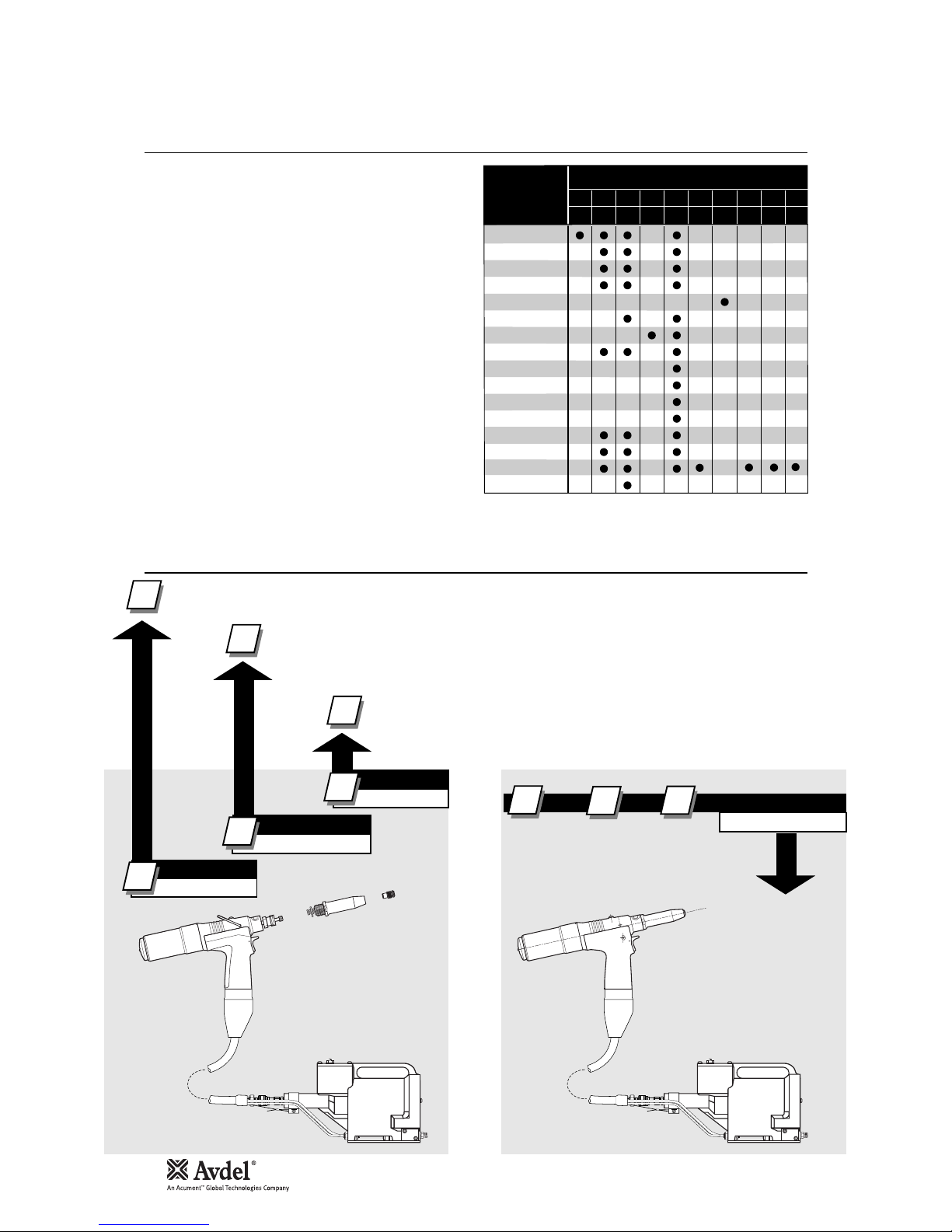
Intent of Use
COMPLETE TOOL
71401-00 . . .
*
BASE TOOL
1
1
2
3
1
NOSE ASSEMBLY
NOSE TIP
2
71401-01000
71213-15000
see note 3
2
3
++=
3
n
G2s is a hydro-pneumatic tool designed to place Avdel
®
breakstem fasteners at high speed making it ideal for batch or
flow-line assembly in a wide variety of applications throughout
all industries. It can place all fasteners listed opposite.
The tool features a vacuum system for fastener retention and
trouble free collection of the spent stems regardless of tool
orientation.
See the ‘Operating Procedure’, page 7, for adjustment
instructions.
A complete tool, except the 71401-00039, is made up of three
separate elements which must be ordered individually.
See diagram below.
If you wish to place most of the fasteners in the table
opposite, you can order the 71401-00039 complete tool
comprising:
• 71401-01000 base tool.
• 71213-15000 nose assembly.
• Nose tips 71210-05002, 71210-16070 and 07381-
04701.
Fit nose tips as indicated on pages 8 to 12.
The part number of the base tool remains the same whichever nose assembly, or nose tip is fitted. For details of the pistol, see
page 26. If a swivel head is fitted, the same base tool must be adapted. See details page 15.
This single nose assembly will allow placing of non-aerospace fasteners by simply selecting the appropriate
nose tip from the range of type 1 nose tips. Other nose assemblies are available for applications with
restricted access, for aerospace and special fasteners. See tables pages 9, 10 and 12. A nose
assemblycan be substituted by a swivel head (see pages 14 to16). In this case the nose tip is part of the
swivel head.
The nose tip part number relates to a specific fastener. If access to the application is
restricted, some extended nose tips are available. See page 12 for selection table.
* ADD 3 DIGITS FROM THE
LAST COLUMN OF A NOSE
TIP TABLE ON PAGE 9, 10
and 12.
FOR TOOLS WITH SWIVEL
HEADS USE TABLE PAGES 14
to 15.
You can order the above three nose tips and nose assembly as a nose assembly kit part number 71213-15100. For some
fasteners, the base tool, nose assembly and nose tip must be ordered separately.
NOSE EQUIPMENT MUST BE FITTED AS DESCRIBED ON PAGE 8.
Part Numbering
FASTENER
NAME
MM
IN
FASTENER SIZE ( )
AVEX
®
STAVEX
®
AVINOX®II
AVIBULB
®
ETR
BULBEX
®
T-LOK
®
AVDEL® SR
MONOBOLT
®
INTERLOCK
®
KLAMPTITETM KTR
KLAMPTITE
TM
AVDEL
®
MBC
®
MBC®/LC
AVSEAL®II
3 3.2 4.0 4.3 4.8 5 5.2 6 6.5 7
–
1/85
/32 –3/16 –––––
Range of Fasteners
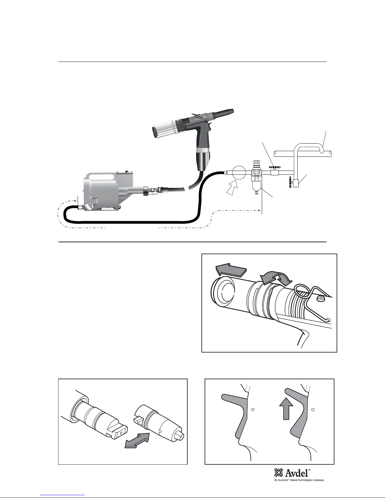
Air Supply
Putting into Service
7
All tools are operated with compressed air at an optimum pressure of 5.5 bar. We recommend the use of pressure regulators and filtering
systems on the main air supply. These should be fitted within 3 metres of the tool (see diagram below) to ensure maximum tool life and
minimum tool maintenance.
Air supply hoses should have a minimum effective working pressure rating of 150% of the maximum pressure produced in the system or
10 bar, whichever is the highest. Air hoses should be oil resistant, have an abrasion resistant exterior and should be armoured where
operating conditions may result in hoses being damaged. All air hoses MUST have a minimum bore diameter of 6.4 millimetres or
1
/4 inch
• Ensure that the correct nose assembly suitable for the fastener
is fitted.
• Connect the tool to the air supply.
• Insert the fastener stem into the nose of the tool. If using a
standard nose assembly, the fastener should remain held in by
the vacuum system.
• Bring the tool with the fastener to the application so that the
protruding fastener enters squarely into the hole of the
application.
• Fully actuate the Trigger. The tool cycle will broach the fastener
and with standard nose assemblies the broken stem will be
projected to the rear of the tool into the collector bottle.
• A partial rotation and pull movement removes the collector
bottle. The Trigger should be lifted to cut-off the vacuum supply
air prior to removing the collector bottle.
• To minimise air consumption, the Trigger should be ‘lifted” to cut-off the vacuum air supply if the tool is not to be used for a period of
time.
Operating Procedure
8
6
4
2
0
1
0
1
2
14
1
6
TAKE OFF POINT
FROM MAIN SUPPLY
STOP COCK
(USED DURING MAINTENANCE
OF FILTER/REGULATOR
OR LUBRICATION UNITS)
MAIN SUPPLY
DRAIN POINT
PRESSURE REGULATOR
AND FILTER
(DRAIN DAILY)
3 METRES MAXIMUM
AIR LUBRICATION
PERMISSABLE
Lift Trigger to
cut-off the
vacuum air
supply.
Do not use tool when Stem
Collector Bottle is removed

8
Fitting Instructions
IMPORTANT
The air supply must be disconnected when fitting or removing nose assemblies.
Item numbers in bold refer to nose assembly components in all 4 Nose Tip tables (pages 9, 10 and 12).
• Lightly coat Jaws 4 with MolyLithium grease*.
• Drop jaws 4 into Jaw Housing 3.
• Insert Jaw Spreader 5 into Jaw Housing 3.
• Locate Buffer 6 on Jaw Spreader 5.
• Locate Spring 7 onto Jaw Spreader 5.
• Insert Detent Sleeve 10 into Jaw Spreader Housing ‘T’ 9. Not applicable to Type 2 and 3 Nose Assemblies.
• Fit Locking Ring 8 onto the Jaw Spreader Housing ‘T’ 9.
• For tools converted to nose assemblies Type 2 and 3, fit Locking Ring 8 onto the Jaw Spreader Housing ‘T’ 9 attached to the
tool.
• Tighten Jaw Housing 3 and assembled components onto Jaw Spreader Housing ‘T’ 9.
• Utilising the ‘T’ section profiles assemble Nose Assembly onto the tool piston via the Male ‘T’ Adaptor (item 1 pages 26-27).
Not applicable to Type 2 and 3 Nose Assemblies.
• Screw the nose tip into Nose Casing 1 and tighten with spanner*.
• Place Nose Casing 1 over Jaw Housing 3 and screw onto the tool, tightening with spanner*.
Nose assemblies should be serviced at weekly intervals. You should hold some stock of all internal components of the nose assembly
and nose tips as they will need regular replacement.
Use Spanner 07900-00849 (supplied with tool) to assist when servicing the nose assembly.
• Remove the nose equipment using the reverse procedure to the ‘Fitting Instructions’.
• Any worn or damaged part should be replaced.
• Clean and check wear on jaws.
• Ensure that the jaw spreader is not distorted.
• Check Spring 7 is not distorted.
* Item included in the nG2s service kit. For complete list see page 20.
Item numbers in bold refer to the nose assembly components in all four Nose Tip tables on pages 9, 10 and 12.
Servicing Instructions
9
A tool (except part number 71401-00039) must always be fitted with the correct nose assembly and nose tip for your fastener and
must be ordered separately, refer to the ‘NOSE TIPS’ tables below and pages 10 and 12.
If your application presents no access restriction use a Type ‘1’ Nose Tip unless you are placing aerospace fasteners which requires a
Type ‘3’ Nose Tip.
Dimensions ‘A’ and ‘B’ below will help you assess the suitability of a particular nose tip.
You should also check that the dimensions of the nose casing will not restrict access to your application. If access is restricted Type
‘2’ Nose Tips are available for some fasteners. Refer to the table on page 12.
It is essential that nose assembly and nose tip are compatible with the fastener prior to operating the tool. If you have ordered a
71401-00039 complete tool, it is important that you check that the nose tip already fitted to the nose assembly is the correct one to
place your fastener by sliding the fastener stem into the nose tip. No force should be required and play should be minimal.
Swivel heads are available as an alternative to nose assemblies when further reach is required. See pages 14 to 16 in the
‘Accessories’ section.
IMPORTANT
Nose assemblies do NOT include nose tips. Nose tips must be ordered separately.
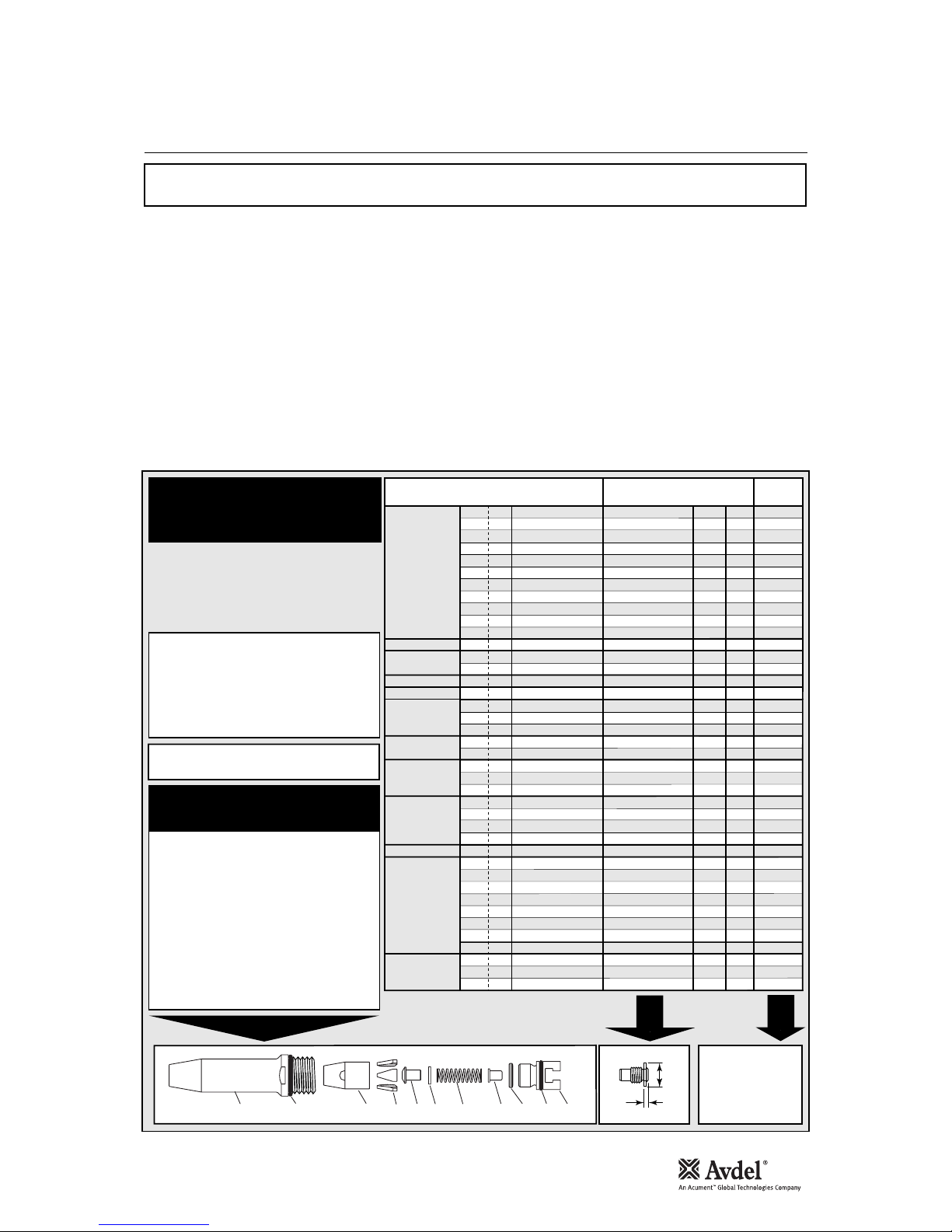
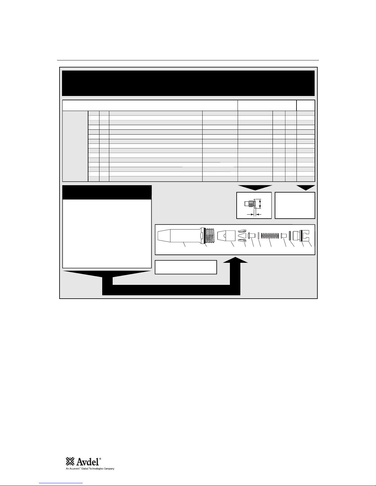
Nose Tips
1
In inches then in millimetres.
2
Head forming nose tips for use with countersunk heads
ONLY.
3
Long nose tip for deep placing.
4
Dome head.
5
Countersunk.
TYPE 1
NOSE TIPS
NOSE ASSEMBLY
part nº 71213-15000
(+ 3 nose tips above = 71213-15100)
FASTENER
MATERIAL
Ø
1
NOSE TIP (mm)
see
below
PART Nº 'A' 'B'NAME
Al Alloy
Steel
Al Alloy
Al Alloy
Al Alloy
Steel
Al Alloy
Al Alloy
Al Alloy
Steel
Al Alloy
Any
Al Alloy
Al Alloy
Al Alloy
Al Alloy
Stainless Steel
Stainless Steel
Stainless Steel
Steel
Steel
Steel
Steel
Steel
Any
Any
Any
Any
Any
Steel
Steel
Steel
Steel
Steel
Stainless Steel
Stainless Steel
Stainless Steel
Any
Any
Any
1
/
8
1
/
8
1
/
8
–
5
/
32
5
/
32
5
/
32
3
/
16
3
/
16
3
/
16
3
/
16
3
/
16
5
/
32
3
/
16
3
/
16
3
/
16
1
/
8
5
/
32
3
/
16
–
3
/
16
1
/
8
5
/
32
3
/
16
1
/
8
5
/
32
3
/
16
3
/
16
3
/
16
1
/
8
5
/
32
3
/
16
3
/
16
3
/
16
1
/
8
5
/
32
3
/
16
1
/
8
5
/
32
3
/
16
4.8
3.3
2.9
4.8
3.3
2.8
3.3
2.8
3.3
3.3
4.1
4.1
3.3
2.8
4.5
2.8
3.3
2.8
4.8
3.3
3.3
3.3
2.8
4.8
4.8
3.3
5.7
5.7
2.8
3.3
2.8
2.8
3.3
2.8
3.3
2.8
2.8
4.8
3.3
3.3
12.7
12.7
12.7
12.7
12.7
12.7
12.7
12.7
19.0
12.7
12.7
12.7
12.7
12.7
12.7
12.7
12.7
12.7
12.7
12.7
12.7
12.7
12.7
12.7
12.7
12.7
12.7
12.7
12.7
12.7
12.7
12.7
19.0
12.7
12.7
12.7
12.7
12.7
12.7
12.7
71210-05002
71210-16070
07340-06401
2
71210-05002
71210-16070
07381-04701
07340-06501
2
07381-04701
07340-04800
07490-04401
07340-06601
2
71210-16020
71210-16070
07381-04701
71220-16060
07381-04701
71210-16070
07381-04701
07498-01401
07340-06201
07340-06201
71210-16070
07381-04701
07498-01401
71210-05002
71210-16070
07348-07001
4
71210-16050
5
07381-04701
71210-16070
07381-04701
07381-04701
07340-04800
07381-04701
71210-16070
07381-04701
07381-04701
71210-05002
07340-06201
07340-06201
3.2
3.2
3.2
3.0
4.0
4.0
4.0
4.8
4.8
4.8
4.8
4.8
4.0
4.8
4.8
4.8
3.2
4.0
4.8
4.3
4.8
3.2
4.0
4.8
3.2
4.0
4.8
1.8
4.8
3.2
4.0
4.8
4.8
4.8
3.2
4.0
4.8
3.2
4.0
4.8
AVEX
®
Large flange
MONOBOLT
®
BULBEX
®
KLAMPTITE™KTR
KLAMPTITE
™
AVINOX® II
T-LOK
®
AVIBULB
®
AVDEL® SR
INTERLOCK
®
STAVEX
®
Large flange
Countersunk
Q-RIVET
™
…039*
…039*
…003
…039*
…039*
…039*
…009
…039*
…016
…017
…015
…200
…039*
…039*
…141
…039*
…039*
…039*
…082
…120
…120
…039*
…039*
…082
…039*
…039*
…062
…064
…039*
…039*
…039*
…039*
…016
…039*
…039*
…039*
…039*
…039*
…120
…120
A
B
ITEM DESCRIPTION PART Nº
1 TAPERED NOSE CASING 71213-00350
2 'O' RING 07003-00067
3 JAW HOUSING - TAPERED 71210-15902 *
4 JAW 71210-15001 *
5 JAW SPREADER 07498-04502 *
6 BUFFER 71210-05001 *
7 SPRING 07500-00418 *
8 LOCKING RING 07340-00327 *
9 JAW SPREADER HOUSING 'T' 71210-20321 *
10 DETENT SLEEVE 71210-20322 *
11 'O' RING 07003-00277 *
*
Complete tool part number 71401-00039 does
not only include the 71213-15000 nose assembly
below but also the following three nose tips:
71210-05002, 71210-16070 and 07381-04701
making up a nose assembly kit part number 71401-
15100.
Use the nose tip listed in the table.
COMPLETE TOOL
PART NUMBER :
precede with 71401-00.
1
2
3
4
5
6
7
10
11
98
*
Items 3-11 available as cartridge assembly
71213-20320
Nose Tips
10
AVSEAL®II
NOSE TIPS
FASTENER
MATERIAL
Ø
1
NOSE TIP (mm)
see
below
PART Nº 'A' 'B'
NAME
Standard Al. Alloy - Flush Nose Tip
Standard Al. Alloy - 2mm Extended Nose Tip
Standard Al. Alloy - 8mm Extended Nose Tip
Standard Al. Alloy - Flush Nose Tip
Standard Al. Alloy - 2mm Extended Nose Tip
Standard Al. Alloy - 8mm Extended Nose Tip
Standard Al. Alloy - Flush Nose Tip
Standard Al. Alloy - 2mm Extended Nose Tip
Standard Al. Alloy - 8mm Extended Nose Tip
Standard Al. Alloy - Flush Nose Tip
Standard Al. Alloy - 2mm Extended Nose Tip
Standard Al. Alloy - 8mm Extended Nose Tip
Standard Al. Alloy - Flush Nose Tip
Standard Al. Alloy - 2mm Extended Nose Tip
Standard Al. Alloy - 8mm Extended Nose Tip
5
/
32
5
/
32
5
/
32
–
–
–
–
–
–
–
–
–
–
–
–
2.5
5.4
11.4
2.5
5.4
11.4
2.5
5.4
11.4
2.5
5.4
11.4
2.5
5.4
11.4
12.7
12.7
12.7
12.7
12.7
12.7
12.7
12.7
12.7
12.7
12.7
12.7
12.7
12.7
12.7
71210-16102
71210-16106
71210-16110
71210-16103
71210-16107
71210-16111
71210-16104
71210-16108
71210-16112
71210-16114
71210-16115
71210-16116
71210-16105
71210-16109
71210-16113
71213-16100
71213-16100
71213-16100
71213-16100
71213-16100
71213-16100
71213-16100
71213-16100
71213-16100
71213-16100
71213-16100
71213-16100
71213-16100
71213-16100
71213-16100
4.0
4.0
4.0
5.0
5.0
5.0
6.0
6.0
6.0
6.5
6.5
6.5
7.0
7.0
7.0
AVSEAL®II
… 401
… 402
… 403
… 404
… 405
… 406
… 407
… 408
… 409
… 413
… 414
… 415
… 410
… 411
… 412
A
B
COMPLETE TOOL
PART NUMBER :
precede with 71401-00.
NOSE ASSEMBLY
part nº 71213-16100
ITEM DESCRIPTION PART Nº
1 TAPERED NOSE CASING 71213-00350
2 'O' RING 07003-00067
3 JAW HOUSING - TAPERED 71210-15902 *
4 JAW 71210-16101 *
5 JAW SPREADER 07498-04502 *
6 BUFFER 71210-05001 *
7 SPRING 07500-00418 *
8 LOCKING RING 07340-00327 *
9 JAW SPREADER HOUSING 'T' 71210-20321 *
10 DETENT SLEEVE 71210-20322 *
11 'O' RING 07003-00277 *
*
Items 3-11 available as cartridge
assembly 71213-16320
1
2
3
4
5
6
7
10
11
98

Fitting Types 2/3 or Nose Extension
11
To fit Nose Tips Type 2/3 or Nose Extension, the ‘T’ Adaptor 1 must be replaced with Jaw Spreader Housing 9*.
• Loosen Locknut 3 using 16mm AF Spanner.
• Unscrew and remove ‘T’ Adaptor 1 together with ‘O’ Ring 2.
1
2
27
43
3
• Fit Jaw Spreader Housing 9* together with ‘O’ Ring 10* (supplied with Type 2 and 3 Nose Assemblies)
• The Jaw Spreader Housing 9* must be tightened onto Head Piston 27 trapping Vacuum Sleeve 43 finally tighten
Locknut 3 against Jaw Spreader Housing 9*.
9*
10*
27
43
Items 9* and 10* refer to nose assembly components in Nose tip tables on page 12.
For other items in bold refer to the general assembly drawing and parts list on pages 26 and 27.
 Loading...