

Avdel HP21, HP41, HP51 Instruction Manual
HydraPac Hydraulic Power Unit
HP 21 , HP 41 , HP 51
I n s t r u c t i o n M a n u a l


3
Co nt en ts
Warranty
The ninety day warranty herein expressed shall be the exclusive warranty on items
manufactured by seller and shall be in the place and stead of any other warranty, expressed or
implied, including but not limited to the implied warranties of merchantability and fitness for a
particular purpose.
Seller shall not be liable for any loss or damage resulting from delays or non-fulfilment or
orders owing to strikes, fires, accidents, transportation companies or for any reason or
reasons beyond the control of seller or its suppliers.
All warranty claims must be submitted to the seller in writing, within 90 days from date of
shipment, and no returns will be accepted without written permission.
Other provisions hereof notwithstanding, seller shall not be liable for any loss of business
profits or any incidental or consequential damages incurred by Buyer or any third person in
connection with the items or use thereof, however caused.
Unit Warranty
Seller expressly disclaims any warranty express or implied, as to the condition, design,
operation, merchantability or fitness for use of any unit, or part(s) thereof not manufactured
and/or supplied by seller. The only warranties made with respect to such unit or part(s)
thereof are those made by the manufacturer thereof and seller agrees to cooperate with buyer
in enforcing such warranties when such action is necessary. Seller agrees to repair or replace
F.O.B. seller's plant, any unit or part(s) thereof manufactured by it and proved to seller to be
defective due to faulty workmanship or material.
Servicing the Tool
Daily / Weekly 21
Every 1200 Working Hours (at least once a year) 21
Service Tools 21
Hydraulic Oil General Safety Data 21
Fault Diagnosis
Symptom, Possible Cause & Remedy 22
Safety Rules 4
Specifications
Intent of Use 5
Tool Specification 5
Tool Dimensions 5
Putting into Service
Principle of Operation 6
Preparation for Use 6
Operating Instructions 6
Mechanical Maintenance
Dismantling Instructions 7
Assembly 8-9
General Assembly and Parts List for HP21 10-11
General Assembly and Parts List for HP41 12-13
General Assembly and Parts List for HP51 14-15
General Assembly and Parts List for
Combination Valve 16
Electrical Maintenance
Minor Maintenance 17
Major Maintenance 17
Assembly 17
Wiring Diagram for HP21 18
Wiring Diagram for HP41 19
Wiring Diagram for HP51 20
Avdel UK Limited policy is one of continuous product development and improvement and we reserve the right to change the specification of any product without prior notice.

4
Sa fe ty
1 Do not use outside the design intent.
2 Do not use equipment with this HydraPac other than that recommended and supplied by Avdel UK Limited.
3 Any modification undertaken by the customer to the HydraPac shall be the customer’s entire responsibility.
4 Always disconnect the HydraPac from the power supply before attempting any work.
5 The HydraPac should always be positioned on a flat stable surface.
6 It is recommended that the HydraPac only be started with hoses and an installation tool attached.
7 Do not fit flexible hoses rated at less than 10 000 psi (69 mPa).
8 The operating pressure shall not exceed 8000 psi (55.2 mPa).
9 Take care to avoid entanglement of the trailing cable with any object on the floor.
10 The HydraPac should be kept clean for safe and easy operation.
11 When moving the HydraPac from place to place only pull on the handle, not on the hoses.
12 Ear protection must be worn by the operator and others in the vicinity utilising lockbolt installation tooling as noise levels for these tools
exceed the permitted maximum. For these values see the installation tool technical manuals.
This instruction manual must be read with particular attention to the following safety rules, by any person
installing, operating, or servicing this tool.
CAUTIONS
AVDEL RECOMMENDS THAT ONLY HYDRADRIV TOOLING BE USED WITH THE HYDRAPACS AS OTHER MAKES OF HYDRAULIC
TOOLING MAY NOT OPERATE AT THE SAFE DESIGNED WORKING PRESSURES.
KEEP DIRT AND FOREIGN MATTER OUT OF THE HYDRAULIC SYSTEMS AS THIS WILL CAUSE THE HYDRAPAC TO
MALFUNCTION.
5
To convert electrical energy into hydraulic energy that in turn will drive various hand held Hydraulic Powered Tools. The design pressures of
these Tools must be compatible with the working pressures stipulated in the Tool Specifications below.
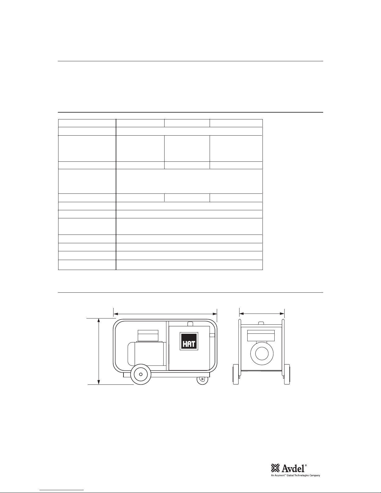
HYDRAPAC
H
L W
Model HP21 HP41 HP51
Electric Motor 2.2 kW 4 pole flange mount
Power Supply 220/230V 380/415V 525V
1PH 3PH 3PH
50 Hz 50 Hz 50Hz
Full Load Amps 15.00 5.3 3.8
Working Pressure
Pull 55.2 mPa (8000 psi)
Return 20.7 ma (3000 psi)
Delivery Volumes 2.6 l/min 3.3 l/min 3.3 l/min
Hydraulic Fluid ISO VG 46 OR EQUIVALENT
Pump 4 Cylinder radial
Control 24V dc solenoid controlled directional valve coupled to
a hydrafast combination pressure control and relief valve
Length (L) 815 mm (32")
Height (H) 530 mm (21")
Width (W) 360 mm (14")
Mass 98 kg with full oil tank
Avdel UK Limited policy is one of continuous product development and improvement and we reserve the right to change the specification of any product without prior notice.
In t e n t o f U s e
To o l S p e c if i c a t i o n
To o l D i m e ns i o n s
Sp ec if ic at io ns

6
Pu tt in g in to S er vi ce
The HydraPac is a High Pressure Hydraulic Pump delivering two different operating pressures for the two cycles of the tooling
operation. A high pressure for the installation cycle (or pull cycle) and a lower pressure for the ejection cycle (or return cycle). Each
HydraPac is provided with 10 m of trailing cable for connection of the electric power supply, a pair of Hydraulic Quick Couplers and an
electrical socket for the Control Cord Connection.
When connected to the correct power supply and then coupled hydraulically and electrically to an Installation Tool, the HydraPac will
start up on depressing the Trigger Switch on the Installation Tool. With the switch remaining depressed, the solenoid valve in the
HydraPac then becomes energised directing the Oil to the High Pressure Installation side of the Installation Tool.
Note: 1. If the Trigger Switch is not released before the piston in the Installation Tool reaches the end of its stroke, the
Combination Valve will enter the idle mode thereby safely dumping all the Hydraulic Pressure into the tank. This
"Dumping" will also occur if any blockage occurs in the Hydraulic System.
2. In the unlikely event of a total failure of the Primary Safety Hydraulic Pressure Relief Valve Mechanism, a second Safety
Relief Valve is located on the Pump Manifold.
On completion of the LockBolt installation cycle, the trigger switch is released, de-energising the Solenoid Valve which directs the
lower pressure oil flow to the return side of the Installation Tool. On completion of the return cycle the Combination Valve automatically
puts the HydraPac into "Idle Mode". The oil continues to flow through the Valve Assembly but returns directly to the tank at the idle
pressure of 1.3 mPa. On depressing the Tool Trigger Switch, the cycle is initiated.
If the Tool Trigger switch in not depressed within a preset period (normally set at 10 seconds for T10 Tools, 15 seconds for T30
Tools, and 25 seconds forT51 Tools), the HydraPac will enter its "Sleep Mode" thereby conserving electricity and wear and tear on the
components.
The period before entering the "Sleep Mode" can be varied to suit the users needs and conditions.
The HydraPac will automatically start up again on depressing the Tool Trigger switch again.
• Check the Oil Level in the Tank using the Gauge located at the front of the HydraPac. Fill and/or top-up as required.
Note: Export units are shipped dry.
• Ensure that the Isolator on the HydraPac Electric Enclosure is turned to "Off''.
• Connect the Power Supply Trailing Cable to the correct power supply for the Hydrapac Model (see page 5) and turn the power
supply switch "On".
• Connect one end of the Hose Set Quick Couplers to the HydraPac and the other end to each other.
• Connect the Hose Set Control Cord to the Socket in the Electrical Enclosure on the HydraPac and to the Installation Tool to be
used.
• Turn the HydraPac Isolator to "On".
• Depress and release the Installation Tool Trigger Switch. The HydraPac should now be running in the "Idle Mode".
• Allow the HydraPac to go into its "Sleep Mode". Repeat this step and the previous step a few times. This will allow the oil to
circulate freely through the hoses and back to the tank removing any possible air from the system.
• With the HydraPac in the "Sleep Mode", connect the Installation Tool to be used to the Hose Set.
• Cycle the Tool a few times checking if the "Sleep Mode" timer allows enough time for the tool to complete its "return cycle".
Note: The timer setting can be increased or decreased to suit individual tools and application conditions.
The HAT System is now ready for use.
For Operating Instructions please refer to the Instructions contained in the Installation Tool Manual.
IMPORTANT
Read the safety rules on page 4 carefully
Pr i n c i p l e o f O p e r a t i o n
Pr e p a r a t i o n f o r U s e
Op e r a t i n g I n s t r u c t i o n s

7
Me ch an ic al M ai nt en an ce
Preparation
• Disconnect and remove the hose set and its control cord from the HydraPac.
• Remove the Tank Cover using a 5 mm allen key.
• Remove the Drain Plug with a 13mm spanner and drain the oil.
• Disconnect the electrical connection from the solenoid on the Valve Set using a 4mm flat screwdriver.
• Remove the steel hydraulic pipe connecting the pump to the Valve Set using a 20 mm spanner.
Removing the Valve Set (C025 and C027)
• Note the relative positions of the Male and Female couplers. Unscrew and remove the Hydraulic Quick Couplers 2 using a 24mm
spanner.
• Unscrew the Bulkhead Adaptors 1 and remove the Valve Set comprising Directional Valve 101B and the Combination Valve 114
using a 27 and a 24 mm spanner.
Separating the Valve Set
• Unscrew and remove the four M5 socket screws located in the Directional Valve 101B using a 4 mm allen key
To Strip the Combination Valve
• Unscrew the four M4 Socket Head Cap Screws 103 securing each of the two Spring Domes 106 using a 3 mm allen key.
• Remove the two Spring Domes and take out the Springs 108 and Bearing Pads 107.
• Remove the two Plungers 109 from the Combination Valve Body 110 taking care to identify each ones own location.
Directional Valve
The only component on this unit that can be replaced is the Solenoid Coil. This can be removed by unscrewing the nylon securing nut
and sliding off the Coil. Care should be taken not to lose the square section rubber cushion between the Nut and the Coil and the 'O'
Ring behind the Coil.
Assembly of the coil is simply the reverse to the stripping procedure above.
Removing the Pump
• Remove the eight M10 Nyloc Nuts 36 using a 17 mm spanner
• Slide the Manifold Flange 7 off the Studs 15.
• Slide the four Pump Elements 8 off the Studs 15 taking care to keep them intact once free of the Bearing 14 by supporting the
Piston with a finger.
Removing the Electric Motor
• Push the connecting block for the solenoid out of the Hirschmann Cap and disconnect the two wires using a 4 mm flat
screwdriver.
• Unscrew and remove the Gland Clamp Screw using a 17 mm spanner and feed the wire through the Gland 18.
• Support the Electric Motor 16 and remove the two M6 Socket Head Cap Screws located inside the Tank using a 5 mm allen key.
• Slide the motor away from the tank.
• The Eccentric Shaft Bearing 14 can be removed with a conventional bearing puller.
Note: Only remove this item if it has to be replaced or the motor stripped for extensive maintenance.
WARNINGS
Before commencing with any maintenance whatsoever, the Isolator on the HydraPac Control Box must be turned
"OFF" and the Power Supply Trailing Cable be disconnected from the power supply.
Due to the high hydraulic operating pressures, it is imperative that only suitably qualified, trained and equipped
personnel be permitted to service or repair these units.
Item numbers in bold refer to the general assembly and combination valve drawings and parts lists on pages 10-16.
Di s m a n t l i n g t h e N o s e A s s e m b l y

8
As s e m b l y
Me ch an ic al M ai nt en an ce
Fitting the Eccentric Bearing
• Remove the Fan Motor Cover by unscrewing the 4 screws using a 6 mm wide screwdriver.
• Place this end of the Shaft against a solid base.
• Fit the Eccentric Shaft Bearing 14 onto the Shaft.
Note: It is strongly recommended that a small press be utilised for this procedure.
• Replace the Fan Cover and 4 screws using a 4 mm screwdriver.
Installing the Electric Motor
• Ensure that both the Motor Flange, the Gasket and the Mounting Plate 17 are free from any dirt.
• Smear both sides of the Gasket with a non-adhesive sealant.
• Supporting the Motor 16 and ensuring that the Electric Enclosure 32 is on top, slide the motor studs through the holes in the
Mounting Plate.
• Secure the Motor to the Plate from inside the Tank with the two M6 Socket Head Cap Screws using a 5 mm allen key
• Feed the Solenoid Wire through the Gland 29 in the Mounting Plate leaving a little slack between the Electric Enclosure Assembly
32 and the Mounting Plate 17 and tighten the Gland Screw using a 17mm spanner.
Installing the Pump
• Ensure that the 'O' rings are firmly in position on each Element's Discharge Port.
• With the Discharge Port facing away from the Mounting Plate 17, lift the Piston against the Spring and slide the Element 8 over
the Studs 15 and the Bearing 14 until they are up against the Mounting Plate. Repeat for all four Elements.
Note: HP41 and HP51 models have four equal size Elements. The HP21 and HP42 however have two different size elements.
Equal size Elements MUST be assembled so that they are diametrically opposed.
• Slide the Manifold Flange 7 over the Studs 15 ensuring that the ports are facing the Elements and that the symbol 'T' is located
on top.
• Tighten the eight Nyloc Nuts 36 to 30 Nm in an opposing sequence using a 17 mm socket and torque wrench.
Assembling the Combination Valve
• Replace the two Plungers 109 in their respective ports.
Note: It is essential for efficient Valve Functioning that the Plungers be placed in their original positions.
• Loosen the two nuts with a 10mm spanner and a 5 mm allen key and back-off the Pressure Adjusting Screws on top of the Spring
Domes 106 about three turns.
• Insert the Bearing Pads 107 and Springs 108 in that order into the Spring Domes 106.
• Locate the Spring Dome Spigots in the matching recesses in the Valve Body 110 and secure with the four Screws 103 in each
Dome using a 3 mm allen key.
Assembling the Valve Set
• Ensure that the four 'O' Ring Seals 113 are in place on top of the face of the Directional Valve 101.
• Place the Directional Valve 101 over the Combination Valve 114, locating the Dowel Pin in the recess provided.
• Secure the two Valves with the four M5 Socket Head Cap Screws 102 using a 4 mm allen key.
Installing the Valve Set
• Screw the two Nuts on the Bulkhead Adaptors 1 as far on as possible by hand and slide the Washers as close as possible to
them.
• Ensuring that the two 'O' Rings 111 are in place over Discharge Ports in the Combination Valve 114, place the Valve over the two
holes provided in the tank.
• Screw the long side of the Bulkhead Adaptors 1 into the ports and tighten using a 24 mm spanner
• Secure the valve set to the tank by tightening the two Nuts up against the Washers with a 27 mm spanner.
• Looking from the non-motor end of the HydraPac, fit the Male Quick Coupler 2A to the Right Hand Side Adaptor and the Female
Quick Coupler 2B to the Left Hand Side and tighten using a 24 mm spanner for both.
Item numbers in bold refer to the general assembly and combination valve drawings and parts lists on pages 10-16.
 Loading...