

Hydro-Pneumatic Power Tool
Druckluftgerät
Outil oléo-pneumatique
Attrezzo oleopneumatico
Genesis
®
Instruction Manual
Manuel d’instructions
Betriebsanleitung
Manuale d’istruzione
G3


3
Safety Instructions 4
Specifications
Tool Specification 5
Tool Dimensions 5
Intent of Use
Range of Fasteners 6
Part Numbering 6
Putting into Service
Air Supply 7
Operating Procedure 7
Nose Assemblies
Fitting Instructions 8
Servicing Instructions 8
Nose Tips 9 - 12
Type 1 Standard 9
Avseal
®
II Nose Tips 10
Type 2 Limited Access 11
Type 3 Aerospace 11
Type 4 Monobolt
® -
Extended 12
Type 5 Avtainer
®
12
Type 6 Monobolt®- Interlock
®
12
Accessories
Stem Deflector 13
Preparing the Base Tool for use with Stem Deflector 13
Extension 13
Swivel Heads 14
Straight Swivel Head capability 14
Preparing the Base Tool for Right-Angle and Straight 15
Swivel Head Attachment
Right-Angle Swivel Head capability 15
Swivel Head Fitting Instructions 16
Swivel Head Servicing Instructions 17
Constant Components 17
Servicing the Tool
Daily / Weekly 18
Moly Lithium Grease EP 3753 Safety Data 18
Molykote
®
55m Grease Safety Data 19
Molykote®111 Grease Safety Data 19
Service Kit 20
Maintenance 20
Nose Equipment 20
Dismantling the Tool 21
Head Assembly 21
Pneumatic Piston Assembly 22
Air Valve 22
Rotary Valve 23
Trigger 23
Stop Plate Assembly (71213-03900) 24
General Assembly of Base Tool
General Assembly 26
Parts List 27
Priming
Oil Details 28
Hyspin
®
VG 32 Oil Safety Data 28
Priming Kit 28
Priming Procedure 29
Fault Diagnosis
Symptom, Possible Cause and Remedy 30
Français 33
Deutsch 63
Italiano 93
Avdel UK Limited policy is one of continuous product development and improvement and we reserve the right to change the specification of any product without prior notice.
LIMITED WARRANTY
Avdel make the limited warranty that its products will be free of defects in
workmanship and materials which occur under normal operating conditions. This
Limited Warranty is contingent upon: (1) the product being installed, maintained and
operated in accordance with product literature and instructions and (2) confirmation by
Avdel of such defect, upon inspection and testing. Avdel makes the forgoing limited
warranty for a period of twelve (12) months following Avdel’s delivery of the product to
the direct purchaser from Avdel. In the event of any breach of the forgoing warranty,
the sole remedy shall be to return the defective Goods for replacement or refund for
the purchase price at Avdel’s option. THE FORGOING EXPRESS LIMITED WARRANTY
AND REMEDY ARE EXCLUSIVE AND ARE IN LIEU OF ALL OTHER WARRANTIES AND
REMEDIES. ANY IMPLIED WARRANTY AS TO QUALITY, FITNESS FOR PURPOSE, OR
MERCHANTABILITY ARE HEREBY SPECIFICALLY DISCLAIMED AND EXCLUDED BY AVDEL.
Contents
English

4
Safety Instructions
1 Do not use outside the design intent.
2 Do not use equipment with this tool/machine other than that recommended and supplied by Avdel UK Limited.
3 Any modification undertaken by the customer to the tool/machine, nose assemblies, accessories or any equipment supplied by Avdel UK
Limited or their representatives, shall be the customer’s entire responsibility. Avdel UK Limited will be pleased to advise upon any
proposed modification.
4 The tool/machine must be maintained in a safe working condition at all times and examined at regular intervals for damage and function
by trained competent personnel. Any dismantling procedure shall be undertaken only by personnel trained in Avdel UK Limited procedures.
Do not dismantle this tool/machine without prior reference to the maintenance instructions. Please contact Avdel UK Limited with your
training requirements.
5 The tool/machine shall at all times be operated in accordance with relevant Health and Safety legislation. In the U.K. the “Health and
Safety at Work etc. Act 1974” applies. Any question regarding the correct operation of the tool/machine and operator safety should be
directed to Avdel UK Limited.
6 The precautions to be observed when using this tool/machine must be explained by the customer to all operators.
7 Always disconnect the airline from the tool/machine inlet before attempting to adjust, fit or remove a nose assembly.
8 Do not operate a tool/machine that is directed towards any person(s) or the operator.
9 Always adopt a firm footing or a stable position before operating the tool/machine.
10 Ensure that vent holes do not become blocked or covered.
11 The operating pressure shall not exceed 7 bar.
12 Do not operate the tool if it is not fitted with a complete nose assembly or swivel head unless specifically instructed otherwise.
13 Care shall be taken to ensure that spent stems are not allowed to create a hazard.
14 Vacuum Air MUST be turned off using the Trigger before removing the Stem Collector Bottle which MUST be emptied when half full.
15 The Tool MUST NOT be operated with the Stem Collector Bottle removed.
16 If the nG3 tool is fitted with a stem deflector, it should be rotated until the aperture is facing away from the operator and other person(s)
working in the vicinity.
17 When using the tool, the wearing of safety glasses is required both by the operator and others in the vicinity to protect against fastener
ejection, should a fastener be placed ‘in air’. We recommend wearing gloves if there are sharp edges or corners on the application.
18 Take care to avoid entanglement of loose clothes, ties, long hair, cleaning rags etc. in the moving parts of the tool which should be kept
dry and clean for best possible grip.
19 When carrying the tool from place to place keep hands away from the trigger/lever to avoid inadvertent start up.
20 Excessive contact with hydraulic fluid oil should be avoided. To minimize the possibility of rashes, care should be taken to wash
thoroughly.
21 C.O.S.H.H. data for all hydraulic oils and lubricants is available on request from your tool supplier.
This instruction manual must be read with particular attention to the following safety rules, by any person
installing, operating, or servicing this tool.
Tool Specification
Specifications
5
Air Pressure Minimum - Maximum 5-7 bar (72.5 - 101.5 psi)
Free Air Volume Required @ 5.5 bar 4.3 litres (0.15 cuft)
Stroke Minimum 26 mm (1.02 in)
Pull Force @ 5.5 bar 12.9 kN (2900 lbf)
Cycle Time Approximately 1.2 seconds
Noise Level 75 dB(A)
Weight Including nose equipment 2.25 Kg
Vibration Less than 2.5 m/s
2
(8.2 ft/s2 )
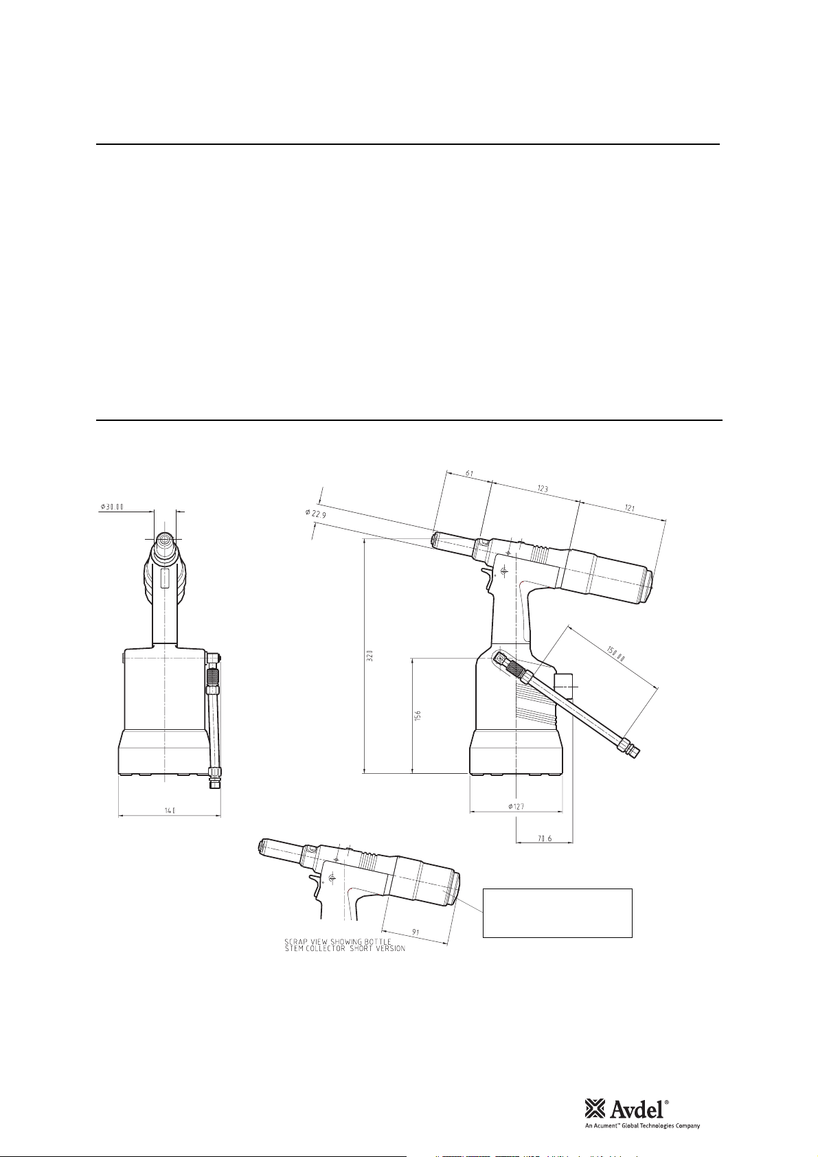
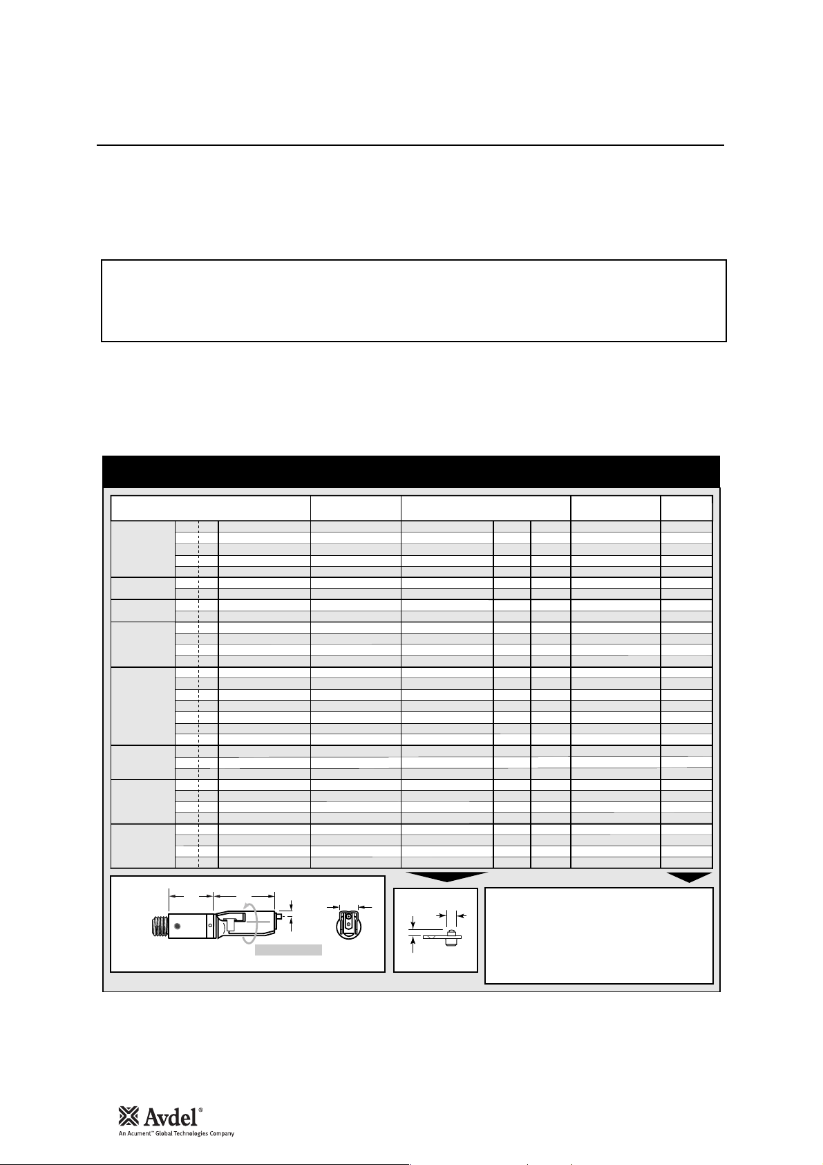
Dimensions in millimetres
Tool Dimensions
Note: Stem Collector Short
Version Bottle is an accessory
part number 71213-03810.
English
6
Intent of Use
nG3 is a hydro-pneumatic tool designed
to place Avdel
®
breakstem fasteners at
high speed making it ideal for batch or
flow-line assembly in a wide variety of
applications throughout all industries. It
can place all fasteners listed opposite.
The tool features a vacuum system for
fastener retention and trouble free
collection of the spent stems
regardless of tool orientation.
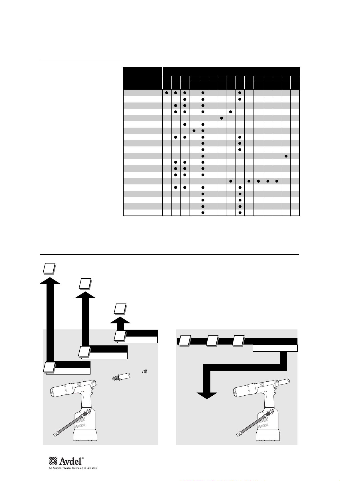
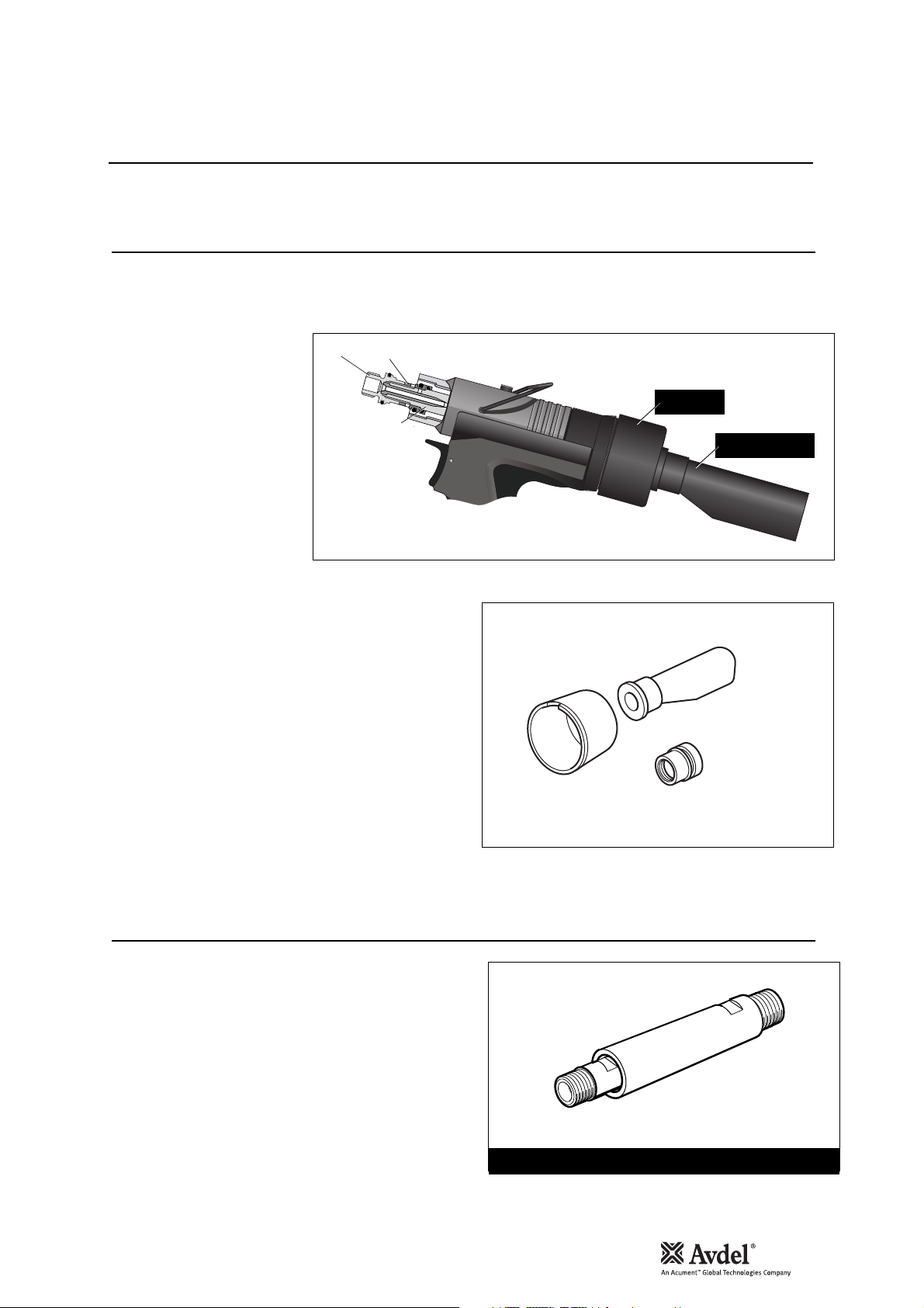
A complete tool is made up of
three separate elements which will
be supplied individually. See
diagram below.
NOSE EQUIPMENT MUST BE
FITTED AS DESCRIBED ON PAGE 8.
The part number of the base tool remains the same whichever nose assembly, or nose tip is fitted. See the General Assembly
pages 26 and 27. If a swivel head is fitted, the same base tool must be adapted. See details pages 14-15.
The nose tip part number relates to a specific fastener. If access to the application is
restricted, some extended nose tips are available. See table pages 11 and 12.
This single nose assembly will allow placing of non-aerospace fasteners by simply selecting the appropriate
nose tip from the range of Type 1 Nose Tips. Other nose assemblies are available for applications with
restricted access, for aerospace and special fasteners. See table page 11. A nose assembly can be
substituted by a swivel head (see pages 14 and 15). In this case the nose tip is part of the swivel head.
* ADD 3 DIGITS FROM THE
LAST COLUMN OF A NOSE
TIP TABLE ON PAGE 9 - 12.
FOR TOOLS WITH SWIVEL
HEADS USE TABLE PAGES 14-
15.
Range of Fasteners
Part Numbering
TIPO
RIVETTO
®
AVEX
®
STAVEX
AVINOX® II
ETR
T-LOK
AVDEL
®
MBC
™ RIVET
™ RIVET
®
®
®
®
®
®
®
®
AVIBULB
BULBEX
AVDEL® SR
MONOBOLT
INTERLOCK
AVTAINER
MBC/LC
AVSEAL® II
Q
T
CHERRYMATE™
KLAMPTITE™
KLAMPTITE™KTR
DIMENSIONI ( )
3 3.2 4.0 4.3 4.8 5 5.2 6 6.4 6.5 7 8 9 9.5 10
– 1
/8 5/32 – 3/16 – – – 1/4 – – – – 3/8 –
MM
Pollici
1
2
NOSE ASSEMBLY
2
71210-15000
BASE TOOL
1
71223-02000
3
3
NOSE TIP
see note 3
1
2
++=
3
COMPLETE TOOL
71223-00 . . .
*
7
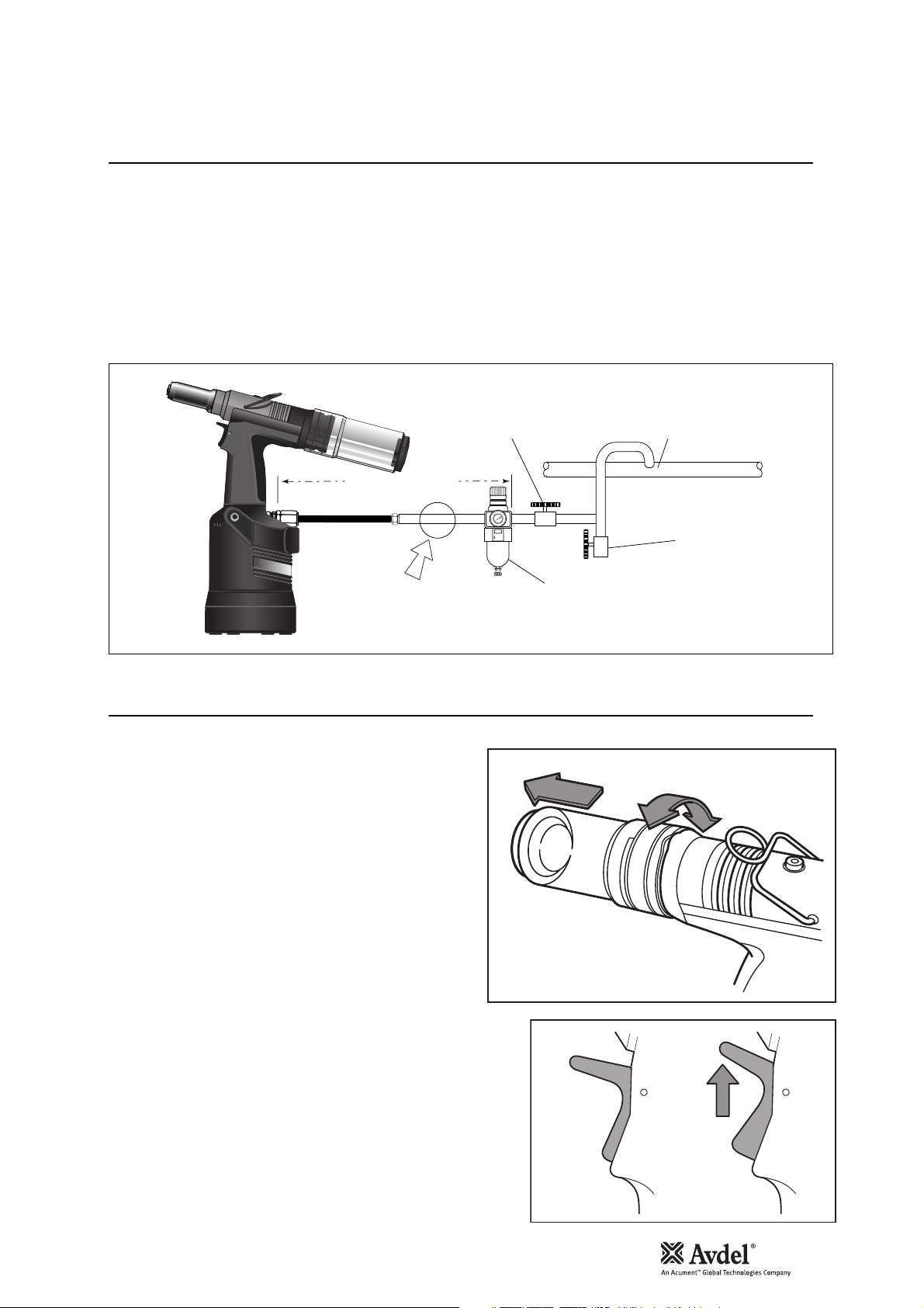
All tools are operated with compressed air at an optimum pressure of 5.5 bar. We recommend the use of pressure regulators and filtering
systems on the main air supply. These should be fitted within 3 metres of the tool (see diagram below) to ensure maximum tool life and
minimum tool maintenance.
Air supply hoses should have a minimum effective working pressure rating of 150% of the maximum pressure produced in the system or
10 bar, whichever is the highest. Air hoses should be oil resistant, have an abrasion resistant exterior and should be armoured where
operating conditions may result in hoses being damaged. All air hoses MUST have a minimum bore diameter of 6.4 millimetres or
1
/4 inch.
• Ensure that the correct nose assembly suitable for the fastener is
fitted.
• Connect the tool to the air supply.
• Insert the fastener stem into the nose of the tool. If using a
standard nose assembly, the fastener should remain held in by the
vacuum system.
• Bring the tool with the fastener to the application so that the
protruding fastener enters squarely into the hole of the
application.
• Fully actuate the trigger. The tool cycle will broach the fastener
and with standard nose assemblies the broken stem will be
projected to the rear of the tool into the collector bottle.
• A partial rotation and pull movement removes the collector bottle.
The Trigger should be lifted to cut-off the vacuum supply air prior
to removing the collector bottle.
Putting into Service
Air Supply
Operating Procedure
• To minimise air consumption, the trigger should be ‘lifted” to cut-off the
vacuum air supply if the tool is not to be used for a period of time.
English
Do not use tool when Stem
Collector Bottle is removed
OF FILTER/REGULATOR OR LUBRICATION UNITS)
(USED DURING MAINTENANCE
3 METRES MAXIMUM
AIR LUBRICATION
PERMISSABLE
STOP COCK
10
8
6
12
4
14
2
16
0
TAKE OFF POINT
FROM
MAIN SUPPLY
MAIN SUPPLY
DRAIN POINT
PRESSURE REGULATOR
AND FILTER (DRAIN DAILY)
Lift Trigger to
cut-off the
vacuum air
supply.

8
Nose Assemblies
* Item included in the nG3 Service Kit. For complete list see page 20.
Fitting Instructions
IMPORTANT
Nose assemblies do NOT include nose tips. Nose tips must be ordered separately.
A complete tool must always be fitted with the correct nose assembly and nose tip for your fastener and must be ordered separately,
refer to the ‘NOSE TIPS’ tables on pages 9 to 12.
If your application presents no access restriction use a Type ‘1’ Nose Tip unless you are placing aerospace fasteners which requires a
Type ‘3’ Nose Tip or Avtainer
®
fasteners a Type 5 Nose Tip.
Dimensions ‘A’ and ‘B’ in the following Nose Tip tables will help you assess the suitability of a particular nose tip.
You should also check that the dimensions of the nose casing will not restrict access to your application. If access is restricted Type
‘2’ Nose Tips are available for some fasteners. Refer to the table on page 11.
It is essential that nose assembly and nose tip are compatible with the fastener prior to operating the tool.
The Type 4 Nose Tip is an alternative to place
1
/4 in Monobolt®. Refer to the table on page 12.
Swivel heads are available as an alternative to nose assemblies as well as an extension when further reach is required.
See pages 14 to 17 in the ‘Accessories’ section.
Nose assemblies should be serviced at weekly intervals. You should hold some stock of all internal components of the nose assembly and
nose tips as they will need regular replacement.
Use Spanner 07900-00849 (supplied with the tool) to assist when servicing the nose assembly.
• Remove the nose equipment using the reverse procedure to the ‘Fitting instructions’.
• Any worn or damaged part should be replaced.
• Clean and check wear on Jaws.
• Ensure that neither the Jaw Spreader nor the Front Spring Guide is distorted.
• Check Spring 7 is not distorted.
• Assemble according to fitting instructions above.
IMPORTANT
The air supply must be disconnected when fitting or removing nose assemblies.
Item numbers in bold refer to nose assembly components in all 5 nose tip tables.
• Lightly coat Jaws 4 with Moly Lithium grease*.
• Drop Jaws 4 into Jaw Housing 3 or Chuck Collet 9 depending on which nose assembly you are using.
• Insert Jaw Spreader 5 into Jaw Housing 3 or insert Front Spring Guide 10 into Chuck Collet 9.
• Locate Buffer 6 on Jaw Spreader 5.
• Locate Spring 7 onto Jaw Spreader 5 or onto Front Spring Guide 10.
• Screw Rear Spring Guide 11 into Chuck Collet 9.
• Fit Locking Ring 8 onto the Jaw Spreader Housing of the tool.
• Holding tool pointing down, screw the assembled Jaw Housing or Chuck Collet onto the Jaw Spreader Housing and tighten with spanner*.
• Screw the nose tip into Nose Casing 1 and tighten with spanner*.
• Place Nose Casing 1 over Jaw Housing 3 or Chuck Collet 9 and screw onto the tool, tightening with spanner*.
Servicing Instructions
Nose Tips
Nose Assemblies
9
English
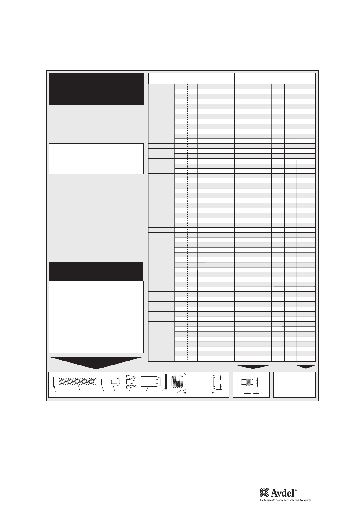
TYPE 1
NOSE TIPS
1
In inches then in millimetres.
2
Head forming nose tips for use with countersunk heads
ONLY.
* In ADDITION to the nose assembly shown below,
an extra long nose assembly is available to place
1
/4" Monobolt® in applications with restricted
access. See type 4 NOSE TIP table.
NOSE ASSEMBLY
part nº 71210-15000
ITEM DESCRIPTION PART Nº
1 NOSE CASING 07340-00306
2 'O' RING 07003-00067
3 JAW HOUSING 07340-00304
4 JAWS 71210-15001
5 JAW SPREADER 07498-04502
6 BUFFER 71210-05001
7 SPRING 07500-00418
8 LOCKING RING 07340-00327
FASTENER
®
AVEX
Large flange
MONOBOLT
BULBEX
®
®
AVINOX®II
®
T-LOK
AVIBULB
®
AVDEL® SR
Countersunk
INTERLOCK
STAVEX
®
®
Large flange
Countersunk
Q™ RIVET
CHERRYMATE™
KLAMPTITE™
KTR
KLAMPTITE™
T™ RIVET
Large flange
Large flange
Large flange
Large flange
4.8
3.3
2.9
4.8
3.3
2.8
3.3
2.8
3.3
3.3
4.1
3.3
4.1
3.3
2.8
3.3
2.8
4.8
3.3
3.3
3.3
2.8
4.8
3.3
4.8
3.3
5.7
5.7
3.3
2.8
3.3
2.8
2.8
3.3
2.8
3.3
2.8
2.8
4.8
3.3
3.3
3.3
3.3
3.3
4.8
4.8
2.8
3.3
6.35
6.35
6.35
6.35
6.65
6.65
6.65
6.65
see
below
…001
…004
…003
…001
…004
…010
…009
…010
…016
…017
…015
…021
…200
…004
…010
…004
…010
…082
…120
…120
…004
…010
…082
…021
…001
…004
…062
…064
…063
…010
…004
…010
…010
…016
…010
…004
…010
…010
…001
…120
…120
…021
…120
…021
…500
…501
…010
…021
…380
…381
…383
…384
…385
…386
…387
…388
1
MATERIAL
Ø
1
/
3.2
Al Alloy
8
1
/
1
/
–
5
/
32
5
/
32
5
/
32
3
/
16
3
/
16
3
/
16
3
/
16
1
/
3
/
16
5
/
32
3
/
16
1
/
8
5
/
32
3
/
16
–
3
/
16
1
/
8
5
/
32
3
/
16
–
1
/
8
5
/
32
3
/
16
3
/
16
1
/
3
/
16
1
/
5
/
32
3
/
16
3
/
16
3
/
16
1
/
5
/
32
3
/
16
1
/
8
5
/
32
3
/
16
1
/
3
/
16
1
/
4
3
/
16
1
/
3
/
16
1
/
3
/
16
3
/
16
3
/
16
3
/
16
1
/
1
/
1
/
1
/
3.2
8
3.2
8
3.0
4.0
4.0
4.0
4.8
4.8
4.8
4.8
6.4
4
4.8
4.0
4.8
3.2
4.0
4.8
4.3
4.8
3.2
4.0
4.8
3.2
4.0
4.8
4.8
6.4
4
4.8
3.2
8
4.0
4.8
4.8
4.8
3.2
8
4.0
4.8
3.2
4.0
4.8
6.4
4
4.8
6.4
4.8
6.4
4
4.8
6.4
4
4.8
4.8
4.8
4.8
6.4
4
6.4
4
6.4
4
6.4
4
Steel
Al Alloy
Al Alloy
Al Alloy
Steel
Al Alloy
Al Alloy
Al Alloy
Steel
Al Alloy
Al Alloy
Any
Al Alloy
Al Alloy
Stainless Steel
Stainless Steel
Stainless Steel
Steel
Steel
Steel
Steel
Steel
Steel
6
Any
Any
Any
Any
Any
Any
Steel
Steel
Steel
Steel
Steel
Stainless Steel
Stainless Steel
Stainless Steel
Any
Any
Any
Any
Any
Any
Any
Any
Any
Any
Al Alloy
Al Alloy
Al Alloy/Steel
Al Alloy/Steel
Al Alloy
Al Alloy
Al Alloy/Steel
Al Alloy/Steel
NOSE TIP (mm)
PART Nº 'A' 'B'NAME
71210-05002
71210-16070
07340-06401
71210-05002
71210-16070
07381-04701
07340-06501
07381-04701
07340-04800
07490-04401
07340-06601
07612-02001
71210-16020
71210-16070
07381-04701
71210-16070
07381-04701
07498-01401
07340-06201
07340-06201
71210-16070
07381-04701
07498-01401
07612-02001
71210-05002
71210-16070
07348-07001
71210-16050
71220-60001
07381-04701
71210-16070
07381-04701
07381-04701
07340-04800
07381-04701
71210-16070
07381-04701
07381-04701
71210-05002
07340-06201
07340-06201
07612-02001
07340-06201
07612-02001
71220-16060
71220-16061
07381-04701
07612-02001
703-A-25-6TA
703-B-21
703-A-25-6T
703-B-26
743-A-25-8TA
703-B-21
743-A-25-8T
743-B-26
2
2
2
12.7
12.7
12.7
12.7
12.7
12.7
12.7
12.7
19.0
12.7
12.7
12.7
12.7
12.7
12.7
12.7
12.7
12.7
12.7
12.7
12.7
12.7
12.7
12.7
12.7
12.7
12.7
12.7
12.7
12.7
12.7
12.7
12.7
19.0
12.7
12.7
12.7
12.7
12.7
12.7
12.7
12.7
12.7
12.7
12.7
12.7
12.7
12.7
12.7
12.7
12.7
12.7
12.7
12.7
12.7
12.7
8 7 6 5 4 23 1
61
22.9
COMPLETE TOOL
PART NUMBER :
A
precede with
B
71223-00
10
Nose Assemblies
Nose Tips
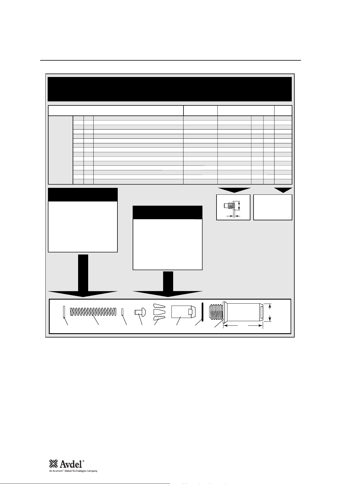
AVSEAL®II
NOSE TIPS
NAME
AVSEAL®II
FASTENER
–
–
–
–
–
–
–
–
–
–
–
–
–
–
–
MATERIAL
Ø
Standard Al. Alloy - Flush Nose Tip
6.0
Standard Al. Alloy - 2mm Extended Nose Tip
6.0
Standard Al. Alloy - 8mm Extended Nose Tip
6.0
Standard Al. Alloy - Flush Nose Tip
6.5
Standard Al. Alloy - 2mm Extended Nose Tip
6.5
Standard Al. Alloy - 8mm Extended Nose Tip
6.5
Standard Al. Alloy - Flush Nose Tip
7.0
Standard Al. Alloy - 2mm Extended Nose Tip
7.0
Standard Al. Alloy - 8mm Extended Nose Tip
7.0
Standard & Low Pressure - Flush Nose Tip
8.0
Standard & Low Pressure - 2mm Ext Nose Tip
8.0
Standard & Low Pressure - 8mm Ext Nose Tip
8.0
Low Pressure Al. Alloy - Flush Nose Tip
9.0
Low Pressure Al. Alloy - 2mm Ext Nose Tip
9.0
Low pressure Al. Alloy - 8mm Ext Nose Tip
9.0
NOSE ASSEMBLY
part nº 71210-16100
ITEM DESCRIPTION PART Nº
1 NOSE CASING 07340-00306
2 'O' RING 07003-00067
3 JAW HOUSING 07340-00304
4 JAWS 71210-16101
5 JAW SPREADER 07498-04502
6 BUFFER 71210-05001
7 SPRING 07500-00418
8 LOCKING RING 07340-00327
NOSE
ASSEMBLY
71210-16100
71210-16100
71210-16100
71210-16100
71210-16100
71210-16100
71210-16100
71210-16100
71210-16100
71220-16100
71220-16100
71220-16100
71220-16100
71220-16100
71220-16100
NOSE ASSEMBLY
part nº 71220-16100
ITEM DESCRIPTION PART Nº
1 NOSE CASING 07340-00306
2 'O' RING 07003-00067
3 JAW HOUSING 07612-02003
4 JAWS 71220-16120
5 JAW SPREADER 07498-04502
6 BUFFER 07498-03003
7 SPRING 07500-00418
8 LOCKING RING 07340-00327
NOSE TIP (mm)
PART Nº 'A' 'B'
71210-16104
71210-16108
71210-16112
71210-16114
71210-16115
71210-16116
71210-16105
71210-16109
71210-16113
71220-16102
71220-16103
71220-16104
71220-16105
71220-16106
71220-16107
12.7
12.7
12.7
12.7
12.7
12.7
12.7
12.7
12.7
14.3
14.3
14.3
12AF
12AF
12AF
A
B
see
below
… 407
2.5
… 408
5.4
… 409
11.4
… 413
2.5
… 414
5.4
… 415
11.4
… 410
2.5
… 411
5.4
… 412
11.4
… 413
2.5
… 414
5.4
… 415
11.4
… 430
3.3
… 431
5.4
… 432
11.4
COMPLETE TOOL
PART NUMBER :
precede with 71223-00.
8 7 6 5 4 23 1
22.9
61
Nose Assemblies
Nose Tips
Note: Items 9 and 10 are not required when assembling Type 2 or Type 3 Nose Tip to the Base Tool nG3 (71223-02000).
Note: Items 9 and 10 are not required when assembling Type 2 or Type 3 Nose Tip to the Base Tool nG3 (71223-02000).
11
English
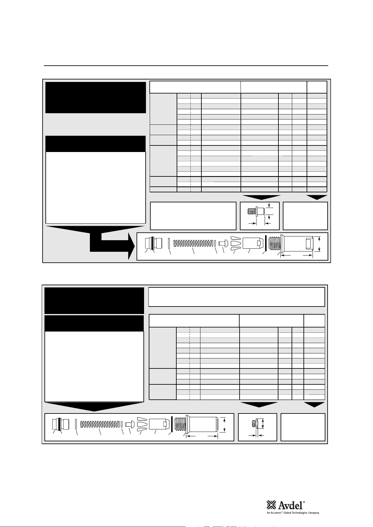
TYPE 2
NOSE TIPS
NOSE ASSEMBLY
part nº 71210-15200
ITEM DESCRIPTION PART Nº
1 NOSE CASING 07340-02804
2 'O' RING 07003-00067
3 JAW HOUSING 07340-00304
4 JAWS 71210-15001
5 JAW SPREADER 07498-04502
6 BUFFER 71210-05001
7 SPRING 07500-00418
8 LOCKING RING 07340-00327
9 JAW SPREADER HOUSING 71210-02101
10 'O' RING 07003-00277
FASTENER
1
MATERIAL
Ø
1
®
AVEX
BULBEX
T-LOK
STAVEX
AVIBULB
E.T.R
1
In inches then in millimetres.
/
3.2
8
1
/
8
5
/
32
5
/
32
3
/
16
3
/
16
5
®
/
32
3
/
16
®
–
3
/
16
1
®
/
8
5
/
32
3
/
16
1
/
8
5
/
32
3
/
16
1
®
/
8
5
/
32
–
Aluminium Alloy
Steel
3.2
Aluminium Alloy
4.0
Steel
4.0
4.8
Aluminium Alloy
4.8
Steel
4.0
Aluminium Alloy
4.8
Aluminium Alloy
4.3
Steel
4.8
Steel
3.2
Steel
4.0
Steel
4.8
Steel
3.2
Stainless Steel
4.0
Stainless Steel
4.8
Stainless Steel
3.2
Steel
4.0
Steel
5.2
Steel/Brass
TYPE 2 NOSE TIPS ARE EXTENDED
TO ALLOW ACCESS INTO
APPLICATIONS WHERE TYPE 1
NOSE TIPS WILL NOT REACH.
8 7 6 5 4239 10
NOSE TIP (mm)
PART Nº 'A' 'B'NAME
07340-02805
07340-02806
07340-02806
07340-02807
07340-02807
07340-07301
07340-02806
07340-02807
07241-07101
07241-07101
07340-02806
07340-02807
07340-02807
07340-02806
07340-02807
07340-02807
07340-02806
07340-02807
07340-02807
A
B
12.95
9.5
9.5
9.5
12.7
12.7
12.7
9.5
12.7
12.7
12.7
9.5
12.7
12.7
9.5
12.7
12.7
9.5
12.7
12.7
COMPLETE TOOL
PART NUMBER :
precede with
58.3
1
11.4
11.4
10.0
10.0
11.8
11.4
10.0
10.0
10.0
11.4
10.0
10.0
11.4
10.0
10.0
11.4
10.0
10.0
71223-00
see
below
…002
…008
…008
…014
…014
…018
…008
…014
…121
…121
…008
…014
…014
…008
…014
…014
…008
…014
…014
22.9
TYPE 3
TYPE 3 NOSE TIPS ARE SPECIFICALLY FOR THE AEROSPACE
FASTENERS LISTED BELOW.
NOSE TIPS
®
®
®
FASTENER
1
Ø
1
/
3.2
8
1
/
3.2
8
1
/
3.2
8
5
/
4.0
32
5
/
4.0
32
5
/
4.0
32
3
/
4.8
16
3
/
4.8
16
1
/
3.2
8
5
/
4.0
32
3
/
4.8
16
1
/
3.2
8
5
/
4.0
32
3
/
4.8
16
MATERIAL
Al Alloy
Al Alloy
O
Stainless Steel
Al Alloy
Al Alloy
O
Stainless Steel
Al Alloy
Al Alloy
O
Any
Any
Al Alloy
Any
Any
Al Alloy
O
Oversize
NOSE ASSEMBLY
part nº 71210-15300
ITEM DESCRIPTION PART Nº
1 NOSE CASING 07344-02001
2 'O' RING 07003-00067
3 JAW HOUSING 07340-00304
4 JAWS 71210-15001
5 JAW SPREADER 07498-04502
6 BUFFER 71210-05001
7 SPRING 07500-00418
8 LOCKING RING 07340-00327
9 JAW SPREADER HOUSING 71210-02101
10 'O' RING 07003-00277
AVDEL
MBC
MBC L/C
1
In inches then in millimetres.
22.9
9 10
8 7 6 5 423
56.3
1
NOSE TIP (mm) see
PART Nº 'A' 'B'NAME
A
12.7
12.7
12.7
12.7
12.7
12.7
12.7
12.7
12.7
12.7
12.7
12.7
12.7
12.7
COMPLETE TOOL
PART NUMBER :
precede with
71210-16030
71210-16031
71210-16032
71210-16033
71210-16034
71210-16035
71210-16036
71210-16037
07340-06701
07340-06801
07340-06901
07344-04701
07344-04701
07344-04701
B
2.5
2.5
3.3
2.5
2.5
3.3
2.5
2.5
4.8
5.0
5.1
4.6
4.6
4.6
71223-00
below
…283
…284
…285
…288
…289
…290
…293
…294
…300
…305
…310
…320
…320
…320
12
Nose Tips
Nose Assemblies
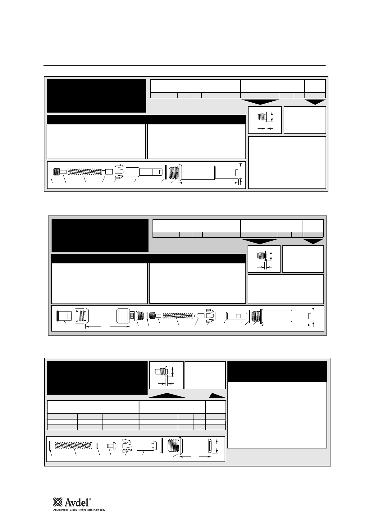
TYPE 4
NOSE TIP
NOSE ASSEMBLY
ITEM DESCRIPTION PART Nº
1 NOSE CASING 07498-00501
2 'O' RING 07003-00067
9 CHUCK COLLET 07498-00502
4 JAWS 07497-03002
11 7 10 4298
TYPE 5
NOSE TIP
NOSE ASSEMBLY
ITEM DESCRIPTION PART Nº
1 NOSE CASING 07498-00501
2 'O' RING 07003-00067
9 CHUCK COLLET 07498-00801
4 JAWS 07220-02302
10 FRONT SPRING GUIDE 07498-00803
FASTENER
1
MATERIAL
Ø
1
/
MONOBOLT
1
In inches then in millimetres
®
6.4
4
Any
part nº 71220-15400
ITEM DESCRIPTION PART Nº
10 FRONT SPRING GUIDE 07498-00507
7 SPRING 07500-02005
11 REAR SPRING GUIDE 07498-00503
8 LOCKING RING 07340-00327
1
FASTENER
3
AVTAINER
1
In inches then in millimetres
®
98.5
1
MATERIAL
Ø
/
9.6
8
Steel
part nº 71220-15500
ITEM DESCRIPTION PART Nº
7 SPRING 07500-02005
11 REAR SPRING GUIDE 07498-00503
8 LOCKING RING 07340-00327
12 SIDE EJECTION ADAPTOR 07498-00900
13 71233-20200
VAC SHUT-OFF STOP NUT ASSY
NOSE TIP (mm) see
PART Nº 'A' 'B'NAME
71220-16021
A
B
FITTED TO THIS LONG NOSE
ASSEMBLY, THE TYPE 4 NOSE TIP
WILL ALLOW THE PLACING OF
1
/4 " MONOBOLT
IN APPLICATIONS REQUIRING
VERY DEEP ACCESS.
20.6
NOSE TIP (mm) see
PART Nº 'A' 'B'NAME
07498-00802
A
B
THERE IS ONLY ONE TYPE 5 NOSE
TIP, SPECIFICALLY DESIGNED TO
PLACE AVTAINER
THIS SPECIAL NOSE ASSEMBLY.
4.114.3
COMPLETE TOOL
PART NUMBER :
precede with
71223-00
®
FASTENERS
4.119.1
COMPLETE TOOL
PART NUMBER :
precede with
71223-00
®
FASTENERS WITH
below
…202
below
…243
28.6
13
90
12 11 7 10 4298
TYPE 6
NOSE TIPS
FASTENER
1
6.4
6.4
6.4
MATERIAL
Any
Any
Any
Ø
1
/
®
MONOBOLT
INTERLOCK
®
STAVEX
4
1
/
®
4
1
/
4
8 7 6 5 4 23 1
B
PART Nº 'A' 'B'NAME
71220-16021
07612-02001
07612-02001
COMPLETE TOOL
A
PART NUMBER
PRECEDED WITH:
71223-00
NOSE TIP (mm) see
14.3
14.3
14.3
4.1
3.6
3.6
above
... 201
... 261
... 261
22.9
61
20.6
1
98.5
NOSE ASSEMBLY
part nº 71230-15800
ITEM DESCRIPTION PART Nº
1 NOSE CASING 07340-00306
2 'O' RING 07003-00067
3 CHUCK COLLET 07612-02003
4 JAWS 07612-02002
5 JAW SPREADER 07498-04502
6 BUFFER 07498-03003
7 SPRING 07500-00418
8 LOCKING RING 07340-00327
1
In inches then in millimetres
Stem Deflector
Accessories
The stem deflector is a very simple alternative to the standard stem collector and allows access in restricted areas. To replace the
stem collector with the stem deflector proceed as follows:
Item numbers in bold refer to the general assembly drawing and parts list on pages 26 and 27.
EXTENSION PART NUMBER: 71210-20300
Fitted between the tool and the nose assembly the extension allows
access into deep channels.
• To fit the extension, remove any nose assembly components.
• Screw the inner extension to Jaw Spreader Housing 41.
• Screw the outer onto Head Assembly 58.
• Fit the nose assembly onto the extension.
• Loosen Locknut 40 using
16mm AF Spanner.
• Unscrew and remove both Jaw
Spreader Housing 41 and
Locknut 40.
• Replace Locknut 40 with
‘Sealed’ Nut 71213-02200,
screw ‘Sealed’ Nut onto Piston
36 to disable Vacuum System.
• Jaw Spreader Housing 41
must be tightened onto Piston
36, finally tightening ‘Sealed’
Nut against it.
• Remove Stop Plate Assembly
(page 24) by unscrewing
Screws 89 (2off).
Extension
Preparing the Base Tool for use with Stem Deflector
The airline must be disconnected before any servicing or dismantling.
‘Sealed’ Nut 71213-02200 replaces Locknut 40 (to cut-off air supply to Vacuum System) as follows:
13
English
• Fit Stem Deflector (07340-00342) into Adaptor (71213-20101).
• Push the assembled Stem Deflector and Adaptor over Bottle
Adaptor 32 and align with the cut-out feature.
41
40
36
71213-20101
ADAPTOR
07340-00342
STEM DEFLECTOR
STEM DEFLECTOR
07340-00342
SEALED NUT
71213-02200
ADAPTOR
71213-20101
INNER
71210-20301
OUTER
71210-20302
14
Swivel Heads
Accessories
Instead of a nose assembly, a swivel head can be fitted to a base tool. It allows 360° rotation of the tool about the nose tip and
allows access into many applications otherwise too restrictive. There are two types of swivel heads: the straight swivel head with the
nose tip slightly offset from the centre line of the tool head and the right-angle swivel head with the nose tip on a perpendicular axis to
the head of the tool. See drawings below for dimensions and pages 16 and 17 for detail.
IMPORTANT
PRIOR to fitting a swivel head, the base tool must be adapted. See Preparing the base tool opposite.
In contrast to nose assemblies part numbers of swivel heads do INCLUDE a nose tip as shown below.
Swivel heads are supplied separately for fitting to a base tool forming a complete tool. See table below for part numbers. Jaws and
nose tips vary depending on the fastener to be placed but all other components remain the same within each type of swivel head. See
the ‘capability’ tables below and page 15. For the ‘Constant Components’ table see page 17.
'A’ and ‘B’ dimensions will help you assess the accessibility of your application.
STRAIGHT SWIVEL HEAD capability
FASTENER
Ø
1
®
AVEX
BULBEX
AVINOX® II
AVSEAL® II
AVDEL
®
MBC
MBC® L/C
STAVEX
®
5
5
3
5
®
3
5
5
5
3
3
5
3
5
5
3
®
1
1
–
–
–
–
1
1
1
1
1
1
5
1
5
/
8
/
8
/
32
/
32
/
16
/
32
/
16
/
8
/
32
/
8
/
8
/
8
/
32
/
32
/
16
/
16
/
8
/
32
/
16
/
8
/
32
/
32
/
16
/
8
/
32
/
8
/
32
3.2
3.2
4.0
4.0
4.8
4.0
4.8
3.2
4.0
4
4
5
5
3.2
3.2
3.2
4.0
4.0
4.8
4.8
3.2
4.0
4.8
3.2
4.0
4.0
4.8
56
1
In inches then in millimetres.
1
MATERIAL
Al Alloy
Steel
Al Alloy
Steel
Al Alloy
Al Alloy
Al Alloy
Stainless Steel
Stainless Steel
Al Alloy
Al Alloy
Al Alloy
Al Alloy
Al Alloy
Al Alloy O
Stainless Steel
Al Alloy
Al Alloy O
Al Alloy
Al Alloy O
Al Alloy
Al Alloy
Al Alloy
Al Alloy
Al Alloy
Al Alloy O
Al Alloy
Steel
3.2
Steel
4.0
Stainless Steel
3.2
Stainless Steel
4.0
92
6
rotation
°
360
2
Long nose tip for deep placing.
PART Nº
07345-03000
07345-03100
07345-03100
07345-03200
07345-03200
07345-03100
07345-03200
07345-03100
07345-03200
71213-06000
71213-06600
71213-06100
71213-06700
07345-03300
07494-03600
07494-03000
07345-03400
07494-03700
07345-03500
07494-03800
07345-04000
07345-04100
07345-04200
07345-04700
07345-04700
07345-04800
07345-04800
07345-03100
07345-03200
07345-03100
07345-03200
20
NOSE TIP (mm)SWIVEL HEAD
PART Nº
07345-03600
07345-03700
07345-03700
07345-03800
07345-03800
07345-03700
07345-03800
07345-03700
07345-03800
71213-16401
71213-16402
71213-16403
71213-16404
07345-03301
07494-03601
07494-03011
07345-03401
07494-03701
07345-03501
07494-03801
07165-00701
07165-00702
07165-00703
07345-04701
07345-04701
07345-04701
07345-04701
07345-03700
07345-03800
07345-03700
07345-03800
A
B
O
Oversize
JAWS
'A' 'B'NAME
3.81
7.87
3.81
7.87
3.81
7.87
3.81
7.87
3.81
7.87
3.81
7.87
3.81
7.87
3.81
7.87
3.81
7.87
1.95
6.35
2
2
6.35
7.62
7.62
5.08
5.08
5.08
6.6
6.6
8.13
8.13
4.75
6.35
7.92
7.87
7.87
7.87
7.87
7.87
7.87
7.87
7.87
4.11
2.00
4.11
1.17
1.17
3.81
0.84
0.84
0.25
0.25
1.9
2.36
2.46
2.03
2.03
2.03
2.03
3.81
3.81
3.81
3.81
PART Nº
07340-00213
07340-00213
07340-00213
07490-04602
07490-04602
07340-00213
07490-04602
07340-00213
07490-04602
07340-00213
07340-00213
07340-00213
07340-00213
07340-00229
07340-00229
07340-00213
07340-00229
07340-00229
07498-04401
07498-04401
07340-00229
07340-00229
07498-04401
07340-00229
07340-00229
07498-04401
07498-04401
07340-00213
07490-04602
07340-00213
07490-04602
…001
…004
…004
…010
…010
…004
…010
…004
…010
…160
…180
…161
…181
…283
…284
…285
…288
…289
…293
…294
…300
…305
…310
…320
…320
…327
…327
…004
…010
…004
…010
COMPLETE TOOL PART NUMBER :
precede with 71223-30
(the stop nut and safety cap are included)
IMPORTANT:
in contrast to complete tools
with nose assemblies, those fitted with swivel heads
include the nose tip as a part of the head.
see
below
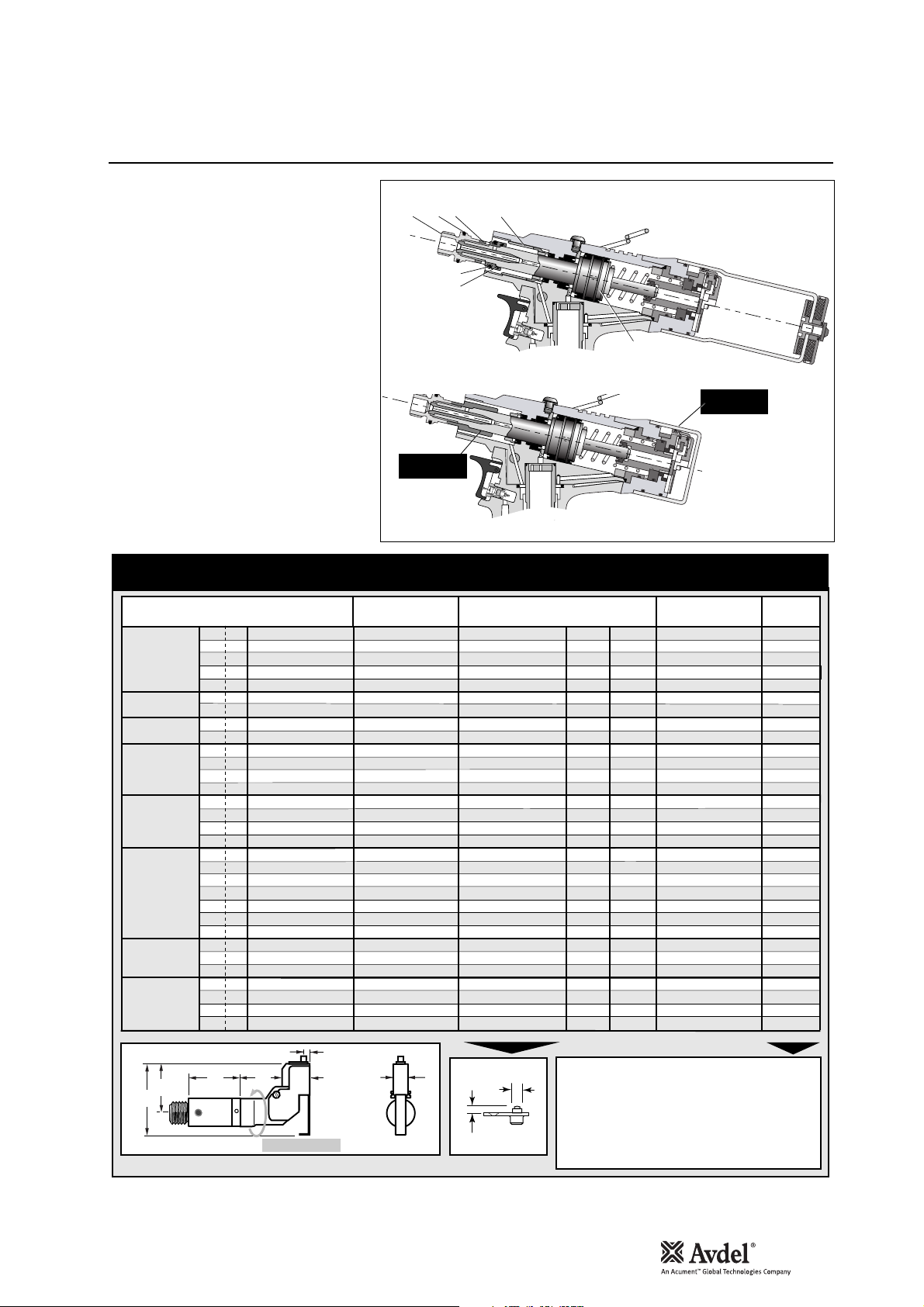
• Disconnect the air supply.
• Remove any nose assembly items.
• Remove Stem Collector Bottle Assembly 25
(71213-03800).
• Replace assembly 25 with Safety Cap
(71213-20201)
• Unscrew Jaw Spreader Housing 41 and
remove with ‘O’ Ring 12, Locknut 40*, ‘O’
Rings 19* and 15*, and Seal Housing 52*.
Do not refit these items (*).
• Screw Stop Nut (71213-20200) onto the
front of Head Piston 36 as far as it will go by
hand.
• Fit Jaw Spreader Housing 41 and ‘O’ Ring 12,
tighten onto Head Piston 36, finally tighten
Stop Nut against Jaw Spreader Housing 41.
The tool is now ready to be fitted with a
swivel head, see page below.
Item numbers in bold refer to the general
assembly drawing and parts list on pages 26 and
27.
Base tool to receive a nose assembly
Base tool to receive a swivel head
Preparing the Base Tool for Right-Angle and Straight Swivel Head Attachment
Accessories
15
English
RIGHT-ANGLE SWIVEL HEAD capability
FASTENER
1
MATERIAL
Ø
®
AVEX
BULBEX
AVINOX
AVSEAL
STAVEX
AVDEL
®
MBC
MBC®L/C
1
/
3.2
8
Aluminium Alloy
1
/
3.2
Steel
8
5
/
4.0
Aluminium Alloy
32
5
/
4.0
Steel
32
3
/
4.8
Aluminium Alloy
16
5
®
/
4.0
Aluminium Alloy
32
3
/
4.8
Aluminium Alloy
16
1
/
®
®
®
3.2
Stainless Steel
8
II
5
/
4.0
Stainless Steel
32
®
–
4
–
–
–
1
/
3.2
8
/
4.0
32
1
/
3.2
8
/
4.0
32
1
/
3.2
8
1
/
3.2
8
1
/
3.2
8
/
4.0
32
/
4.0
32
/
4.8
16
/
4.8
16
1
/
3.2
8
/
4.0
32
/
4.8
16
1
/
3.2
8
/
4.0
32
/
4.0
32
/
4.8
16
4
5
5
Aluminium Alloy
Aluminium Alloy
Aluminium Alloy
Aluminium Alloy
Steel
Steel
Stainless Steel
Stainless Steel
Aluminium Alloy
Aluminium Alloy O
Stainless Steel
Aluminium Alloy
Aluminium Alloy O
Aluminium Alloy
Aluminium Alloy O
Aluminium Alloy
Aluminium Alloy
Aluminium Alloy
Aluminium Alloy
Aluminium Alloy
Aluminium Alloy O
Aluminium Alloy
II
5
5
5
5
3
3
5
3
5
5
3
41 12 40 52
19
15
71213-20200
STOP NUT
NOSE TIP (mm)SWIVEL HEAD
PART Nº
07346-03000
07346-03100
07346-03100
07346-03200
07346-03200
07346-03100
07346-03200
07346-03100
07346-03200
71213-04000
71213-04700
71213-04100
71213-04800
07346-03100
07346-03200
07346-03100
07346-03200
07346-03300
07495-03600
07495-03000
07346-03400
07495-03700
07346-03500
07495-03800
07346-04000
07346-04100
07346-04200
07346-04500
07346-04500
07346-04600
07346-04600
PART Nº
07345-03600
07345-03700
07345-03700
07345-03800
07345-03800
07345-03700
07345-03800
07345-03700
07345-03800
71213-16401
71213-16402
71213-16403
71213-16404
07345-03700
07345-03800
07345-03700
07345-03800
07345-03301
07494-03601
07494-03011
07345-03401
07494-03701
07345-03501
07494-03801
07165-00701
07165-00702
07165-00703
07345-04701
07345-04701
07345-04701
07345-04701
36
71213-20201
SAFETY CAP
View with 25 removed
and stop nut
replacing removed
items 19, 15, 52, 40
JAWS
'A' 'B'NAME
3.81
7.87
3.81
7.87
3.81
7.87
3.81
7.87
3.81
7.87
3.81
7.87
3.81
7.87
3.81
7.87
3.81
7.87
1.95
6.35
2
2
6.35
7.62
7.62
7.87
7.87
7.87
7.87
5.08
5.08
5.08
6.6
6.6
8.13
8.13
4.75
6.35
7.92
7.87
7.87
7.87
7.87
4.11
2.00
4.11
3.81
3.81
3.81
3.81
1.17
1.17
3.81
0.84
0.84
0.25
0.25
1.9
2.36
2.46
2.03
2.03
2.03
2.03
PART Nº
07340-00213
07340-00213
07340-00213
07490-04602
07490-04602
07340-00213
07490-04602
07340-00213
07490-04602
07340-00213
07340-00213
07340-00213
07340-00213
07340-00213
07490-04602
07340-00213
07490-04602
07340-00229
07340-00229
07340-00213
07340-00229
07340-00229
07498-04401
07498-04401
07340-00229
07340-00229
07498-04401
07340-00229
07340-00229
07498-04401
07498-04401
see
below
…001
…004
…004
…010
…010
…004
…010
…004
…010
…160
…180
…161
…181
…004
…010
…004
…010
…283
…284
…285
…288
…289
…293
…294
…300
…305
…310
…320
…320
…327
…327
56
74
97
1
In inches then in millimetres.
52
7.6
32
20
rotation
°
360
2
Long nose tip for deep placing. O Oversize
A
COMPLETE TOOL PART NUMBER :
precede with 71223-40
(the stop nut and safety cap are included)
B
IMPORTANT:
with nose assemblies, those fitted with swivel
in contrast to complete tools
heads include the nose tip as a part of the head.
16
Accessories
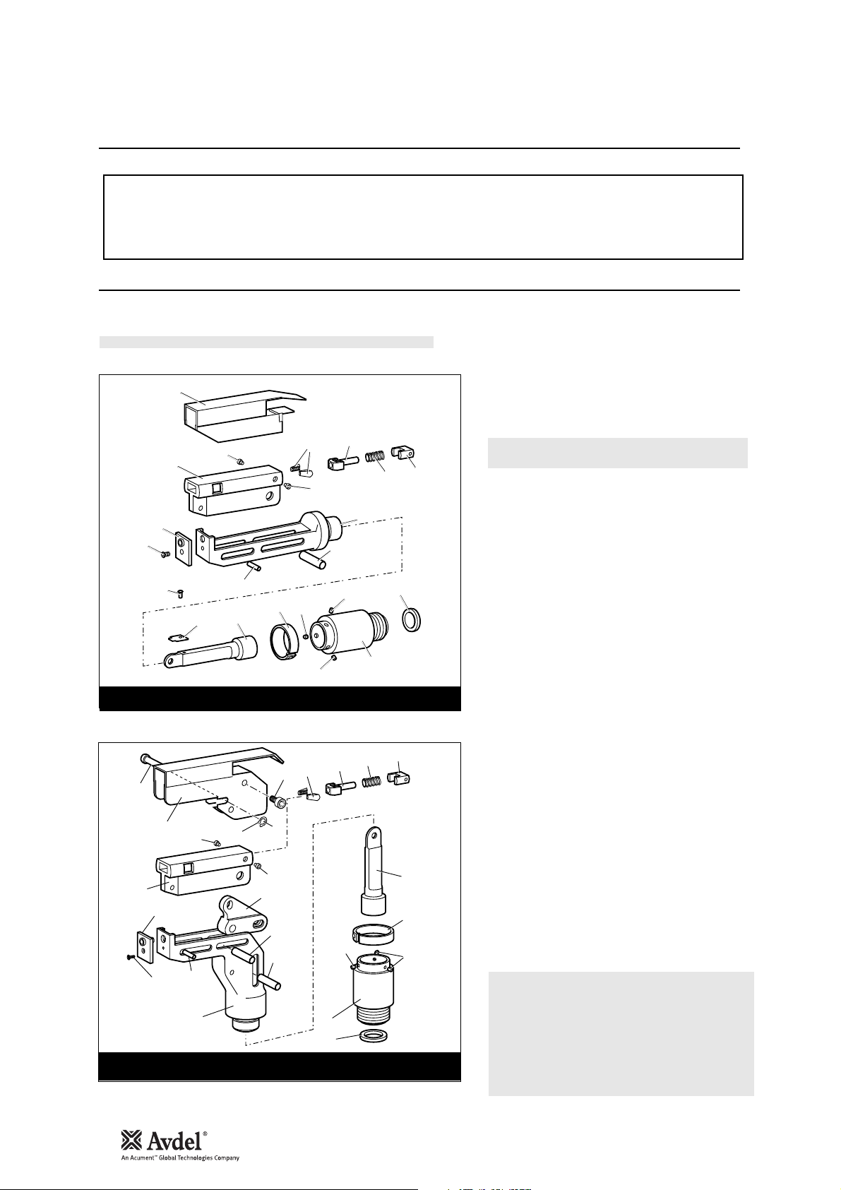
The fitting and servicing procedures for both types of head are almost identical. Differences are clearly indicated.
IMPORTANT
PRIOR to fitting a swivel head, the base tool must be adapted. See Preparing the base tool opposite.
The air supply must be disconnected when fitting or removing swivel heads.
A Fit Locking Ring 10 over Jaw Spreader Housing 41*
(71210-02101). *See pages 26 and 27.
B Coat Screw 13 with thread locking adhesive and use to
secure Nose Tip 14 onto Body 5.
C Lightly lubricate items 17, 18, 19, 20 and insert into
Jaw Carrier 3 as shown. Secure with Screws 16.
D Position Lever 4 into Body 5 and hold in place with pin
15 through the hole of Body 5 (not a slot).
E Lubricate the sides of the Jaw Carrier Assembly and
insert into Body 5.
F Lubricate Rollers 8 and ENSURE that they will freely
rotate in the holes of Adaptor 9. If necessary ream the
holes.
G Position Spring Clip 7 over Adaptor 9 past the holes for
the rollers and rotate until the locating peg is aligned
with the corresponding hole in Adaptor 9 (smallest
hole).
H Fit Adaptor 9 over the end of Body 5 and drop Rollers 8
into place. Push Spring Clip 7 over Rollers 8.
I Insert Spindle 11 through Adaptor 9 into Jaw Carrier 3
until the hole lines up with slot in Body 5. Temporarily
hold in place with Pin 6.
J Insert Pin 12 through the front slot of Body 5 into Jaw
Carrier 3.
K Hold the assembly vertical to prevent all pins dropping
out and slide the jaw carrier assembly back and forth a
few times to ensure free movement. Go to M
.
L Remove Screws 23 (4 off) and guard 1. On a straight
swivel head also remove Screw 21 and Platform 22.
M Push Pin(s) 6 out and let Spindle 11 drop out. Screw
Spindle 11 onto the Jaw Spreader Housing of the tool,
leaving the small screw fixing hole uppermost for
straight swivel. Tighten gently with a tommy bar.
N Screw the assembly over Spindle 11 onto the tool
handle. Replace Pin(s) 6.
O On straight swivel heads attach Platform 22 onto the
top of the Spindle with Screw 21. Deburr the back end
of Platform 22 so that it cannot catch on Guard 1.
P Snap Guard 1 over the assembly, align screw holes in
guard with tapped holes in body assembly.
Q Insert Pivot Pin 15 through slots in guard and hole in
body. Fit Circlip 2 onto pivot pin so that the circlip seats
in groove provided.
R Coat the thread of Screws 23 (4 off) with thread locking
adhesive and screw into body assembly securing guard
to body assembly.
Swivel Head Fitting Instructions
The following procedure will allow you to assemble and fit either of the swivel heads to the tool. If you order a complete swivel head
rather than individual components, you will only need to start at stage ‘L’.
All moving parts should be lubricated. Unless stated otherwise use Moly Lithium grease (details page 18).
When on grey tint, instructions refer only to the right-angle swivel head. Item numbers in bold refer to illustrations below.
STRAIGHT SWIVEL HEAD
RIGHT-ANGLE HEAD
15
13
1
18
14
3
16
17
16
20
19
5
6
21
12
22
11
7
8
8
8
10
9
23
17
18
19
20
1
16
2
3
14
12
13
5
16
4
6
6
8
9
10
11
7
8
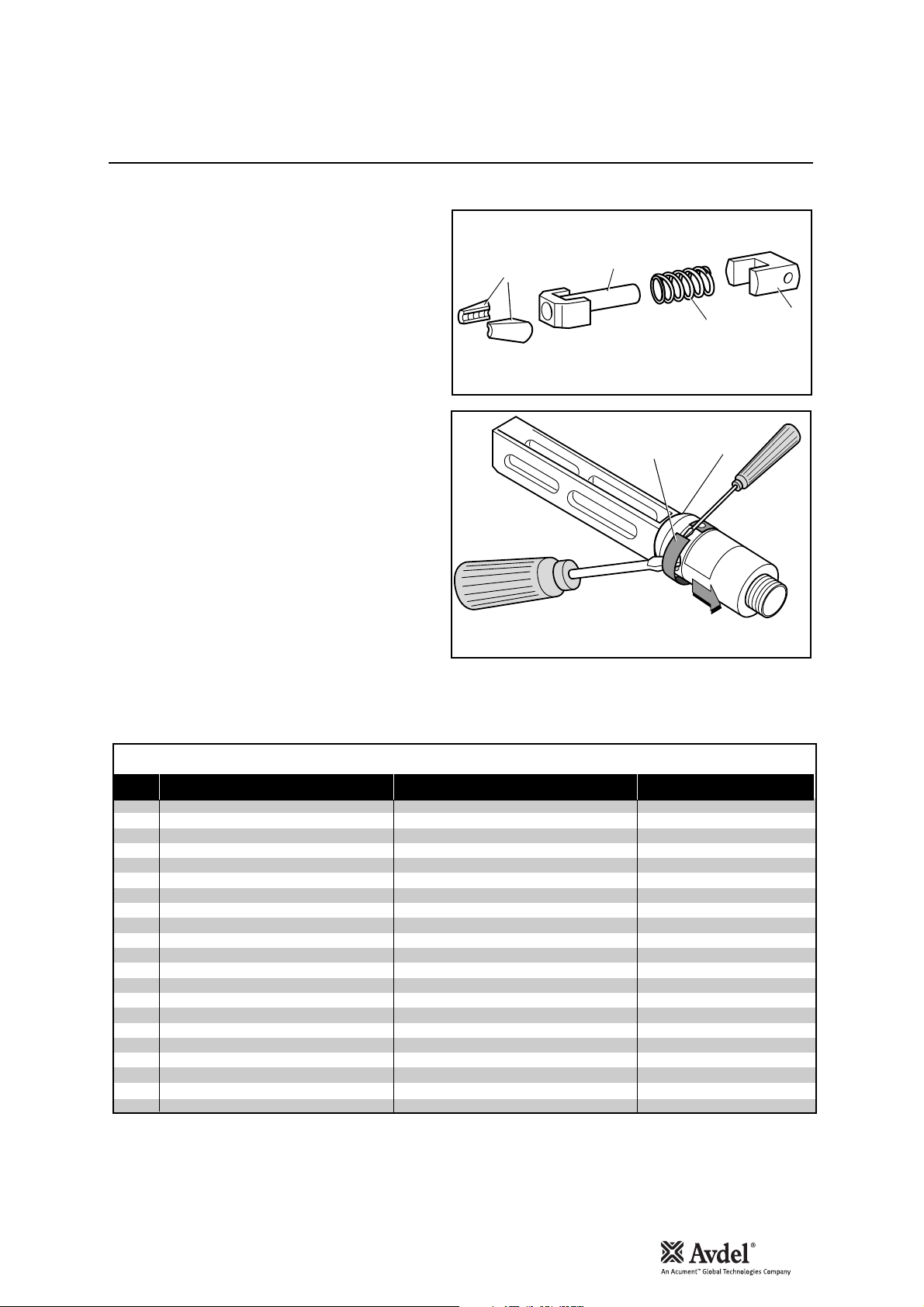
Swivel Head Servicing Instructions
Accessories
5
7
17
18
19
20
Swivel heads should be serviced at weekly intervals.
• Remove the complete head using the reverse procedure to
the ‘Fitting instructions’ omitting step ‘L’.
• If Guard 1 is at all damaged it must be replaced by a new
one.
• Any worn or damaged parts should be replaced.
• Pay particular attention to jaw carrier items in the upper
illustration opposite as follows:
Check wear on Jaws 17.
Check that Jaw Spreader Tube 18 is not distorted.
Check that Spring 19 is neither broken or distorted.
Check that Spring Guide 20 is not damaged.
• Check that spring clip 7 is not distorted. When removing
Spring Clip 7, use two screwdrivers as shown in the lower
illustration opposite.
• Check for excessive wear on slots of Body 5.
• Assemble according to fitting instructions.
Item numbers in bold refer to Swivel Head illustrations on
this page. Guard 1 refers to illustration on page 16.
While nose tips and jaws will vary for each swivel head, other components remain constant within each type of head. See table below
For nose tips and jaws part numbers see within the table on pages 9 to 12.
CONSTANT COMPONENTS
ITEM DESCRIPTION STRAIGHT SWIVEL RIGHT-ANGLE SWIVEL
1
2
3
4
5
6
7
8
9
10
11
12
13
15
16
18
19
20
21
22
23
GUARD
CIRCLIP
JAW CARRIER
LEVER
BODY
PIVOT PIN
SPRING CLIP
ROLLER
ADAPTOR
LOCKING RING
SPINDLE
DOWEL PIN
SCREW
PIVOT PIN
SCREW
JAW SPREADER
SPRING
SPRING GUIDE
SCREW
PLATFORM
SCREW
07494-05000
-
07494-03026
07494-03015
07343-02207
07495-03900
07007-00039
07345-03001
07345-03003
07345-03002
07007-00038
07342-02207
07494-03028
07346-03101
07165-00305
07494-03027
07001-00368
07345-00401
-
07495-03003
07004-00105
07494-03026
07495-03004
07495-03002
07343-02207
07495-03900
07007-00039
07345-03001
07345-03003
07345-03002
07007-00038
07342-02207
07343-02207
07494-03028
07346-03101
07165-00305
07494-03027
–
–
07210-00804
17
English

18
Servicing the Tool
• Daily, before use or when first putting the tool into service, pour a few drops of clean, light lubricating oil into the air inlet of the tool
if no lubricator is fitted on air supply. If the tool is in continuous use, the air hose should be disconnected from the main air supply
and the tool lubricated every two to three hours.
• Check for air leaks. If damaged, hoses and couplings should be replaced.
• If there is no filter on the pressure regulator, bleed the air line to clear it of accumulated dirt or water before connecting the air hose
to the tool. If there is a filter, drain it.
• Check that the nose assembly or swivel head is correct for the fastener to be placed.
• Check the stroke of the tool meets the minimum specification (page 5). The last step of the Priming Procedure on page 29 explains
how to measure the stroke.
• Either a stem collector or a stem deflector must be fitted to the tool unless using a swivel head.
• Check that Base Cover 31 is fully tightened onto Body 30.
• Stem Collector Bottle: ‘O’ Rings 20 and 28 to be checked for wear, cleaned and lubricated with Molykote
®
55m.
• Dismantle and clean the nose assembly with special attention to the jaws. Lubricate with Moly Lithium grease before assembling.
• Check for oil leaks and air leaks in the air supply hose and fittings.
Grease can be ordered as a single item, the part number is shown in the Service Kit page 19.
First Aid
SKIN:
As the grease is completely water resistant it is best removed with an approved emulsifying skin cleaner.
INGESTION:
Ensure the individual drinks 30ml Milk of Magnesia, preferably in a cup of milk.
EYES:
Irritant but not harmful. Irrigate with water and seek medical attention.
Fire
FLASH POINT: Above 220°C.
Not classified as flammable.
Suitable extinguishing media: CO
2
, Halon or water spray if applied by an experienced operator.
Environment
Scrape up for burning or disposal on approved site.
Handling
Use barrier cream or oil resistant gloves
Storage
Away from heat and oxidising agent.
Item numbers in bold refer to the general assembly drawing and parts list on pages 26 and 27.
IMPORTANT
Read Safety Instructions on page 4.
The employer is responsible for ensuring that tool maintenance instructions are given to the appropriate personnel.
The operator should not be involved in maintenance or repair of the tool unless properly trained.
The tool shall be examined regularly for damage and malfunction.
Daily
Weekly
Moly Lithium Grease EP 3753 Safety Data

Molykote®55m Grease Safety Data
First Aid
SKIN:
Flush with water. Wipe off.
INGESTION:
No first aid should be needed.
EYES:
Flush with water.
Fire
FLASH POINT: Above 101.1°C. (closed cup)
Explosive Properties: No
Suitable Extinguishing Media: Carbon Dioxide Foam, Dry Powder or fine water spray.
Water can be used to cool fire exposed containers.
Environment
Do not allow large quantities to enter drains or surface waters.
Methods for cleaning up: Scrape up and place in suitable container fitted with a lid. The spilled product produces an extremely
slippery surface.
Harmful to aquatic organisms and may cause long-term adverse effects in the aquatic environment. However, due to the physical
form and water - insolubility of the product the bioavailability is negligible.
Handling
General ventilation is recommended. Avoid skin and eye contact.
Storage
Do not store with oxidizing agents. Keep container closed and store away from water or moisture.
First Aid
SKIN:
No first aid should be needed.
INGESTION:
No first aid should be needed.
EYES:
No first aid should be needed.
INHALATION:
No first aid should be needed.
Fire
FLASH POINT: Above 101.1°C. (closed cup)
Explosive Properties: No
Suitable Extinguishing Media: Carbon Dioxide Foam, Dry Powder or fine water spray.
Water can be used to cool fire exposed containers.
Environment
No adverse effects are predicted.
Handling
General ventilation is recommended. Avoid eye contact.
Storage
Do not store with oxidizing agents. Keep container closed and store away from water or moisture.
Molykote®111 Grease Safety Data
Servicing the Tool
19
English

20
Service Kit
For an easy complete service, Avdel®offers the complete service kit below.
Servicing the Tool
Maintenance
The airline must be disconnected before any servicing or dismantling is attempted unless specifically instructed otherwise.
It is recommended that any dismantling operation be carried out in clean conditions.
Before proceeding with dismantling, empty the oil from the tool following the first three steps of the ‘Priming Procedure’ on page 28.
Prior to dismantling the tool it is necessary to remove the nose equipment. For instructions see the nose assemblies section, pages 9
to 12 or if a swivel head was fitted pages 14 and 15.
For a complete service of the tool, we advise that you proceed with dismantling of sub-assemblies in the order shown.
After any dismantling REMEMBER to prime the tool and to fit an appropriate nose assembly or swivel head.
(Annually or every 500,000 cycles whichever is the soonest)
Annually or every 500,000 cycles the tool should be completely dismantled and new components should be used where worn,
damaged or recommended. All ‘O’ rings and seals should be renewed and lubricated with Molykote
®
55m grease for pneumatic
sealing or Molykote
®
111 for hydraulic sealing.
IMPORTANT
Read Safety Instructions on page 4.
The employer is responsible for ensuring that tool maintenance instructions are given to the appropriate
personnel.
The operator should not be involved in maintenance or repair of the tool unless properly trained.
Nose Equipment
• Unscrew Nose Casing 1 and Nose Tip.
• Unscrew Jaw Housing 3 and remove Jaws 4, Jaw Spreader 5, Spring 7 and Buffer 6.
• Inspect all components. Renew all damaged or worn parts.
• Clean all parts and apply Moly Lithium Grease EP 3753 (07992-00020) to taper bore of Jaw Housing.
• Insert Jaws 4, Jaw Spreader 5, Spring 7 and Buffer 6 into Jaw Housing 3 and assemble onto Jaw Spreader Housing 41*.
• Screw Nose Tip into Nose Casing and tighten.
Item numbers in bold refer to Nose Tip Tables on pages 9 to 12.
41* refers to illustration on page 25.
SERVICE KIT : 71210-99990 Spanners are specified in inches and across flats unless otherwise stated
®
®
®
07900-00667 PISTON SLEEVE
07900-00692 TRIGGER VALVE EXTRACTOR
07900-00670 BULLET
07900-00672 'T' SPANNER
07900-00706 'T' SPANNER SPIGOT
07900-00684 GUIDE TUBE
07900-00685 INSERTION ROD
07900-00351 3 MM ALLEN KEY
07900-00469 2.5 MM ALLEN KEY
07900-00158 2 MM PIN PUNCH
07900-00224 4 MM A/F ALLEN KEY
07900-00734 STOP NUT - MAXLOK
®
PART Nº DESCRIPTIONPART Nº DESCRIPTION
07900-00164 CIRCLIP PLIERS
07900-00008
07900-00012
07900-00015
07900-00686 PEG SPANNER
07900-00677 SEAL EXTRACTOR
07900-00698 STOP NUT
07900-00700 PRIMING PUMP
07992-00020 GREASE - MOLY LITHIUM E.P.3753
07992-00075 GREASE - MOLYKOTE 55M
07900-00755 GREASE - MOLYKOTE 111
7
/16 x 1/2 SPANNER
9
/16 x 5/8 SPANNER
5
/8 x 11/16 SPANNER

Dismantling the Tool
Servicing the Tool
Before dismantling the tool the oil must be emptied from it.
• With the air supply switched OFF at ON/OFF Valve Assembly 62 remove Bleed Screw 1 and Bonded Seal 6.
• Insert tool over a suitable container, switch air supply ON and actuate tool.
• Oil will expel from bleed screw orifice into container.
• Switch air supply OFF after all oil is expelled.
This operation must have the Bleed Screw orifice facing away from the person performing this operation.
• Twist and pull off Stem Collector Bottle Assembly 25. See illustration on page 7.
• Remove Stop Plate Assembly 104 by unscrewing Screws 89 2 off.
• Unscrew Retaining Nut 50.
• Pull off Bottle Adaptor Assembly 32 together with ‘O’ Rings 20 and 28.
• Remove End Cap Assembly 35 together with ‘O’ Ring 97 and Lip Seal 9.
• Remove Spring 91.
• Loosen Locknut 40 with a spanner* and unscrew Jaw Spreader Housing 41 together with ‘O’ Ring 12.
• Remove Locknut 40 together with ‘O’ Rings 19 and 15, withdraw Vacuum Sleeve 42..
• Push Head Piston 36 to the rear and out of Head Assembly 58 taking care not to damage the cylinder bore
• Using circlip pliers* remove Seal Retainer 43. Push Lip Seal 8 and Bearing Tape 26 to the rear and out of Head Assembly 58 taking
care not to damage the cylinder bore.
• Remove Seal Housing 52 and Lip Seal 2.
Assemble in reverse order noting the following points:
• Place Lip Seal 8 onto the insertion rod* ensuring correct orientation. Locate the guide tube* into the head of the tool and push the
insertion rod* with the seal in place through the guide tube*. Pull the insertion rod* out and then the guide tube*.
• The chamfered edge of Seal Retainer 43 must face forward with the gap at the bottom.
• After fitting Lip Seal 11, ‘O’ Rings 18 and Bearing Tape 27 onto the Head Piston 36 ensuring correct orientation, lubricate the cylinder
bore and place the piston sleeve* into the back of Head Assembly 58. Slide the bullet* onto the threaded part of Head Piston 36 and
push the piston with the seals through the piston sleeve* as far as it will go. Slide the bullet* off the piston and remove piston sleeve*.
• Jaw Spreader Housing 41 must be fully tightened onto Head Piston 36 before tightening Locknut 40 against it.
• Reprime in accordance with the instructions on page 29.
* Item included in the nG3 Service Kit. For complete list see page 20.
Item numbers in bold refer to the general assembly drawing and parts list on pages 26 and 27.
Head Assembly
21
English

22
• Remove ‘ON/OFF’ valve assembly 62.
• Clamp the body of the inverted tool ACROSS THE AIR INLET BOSSES in a vice fitted with soft jaws.
• Pull off Rubber Boot 48.
• Using the peg spanner* unscrew Base Cover 31.
• Unscrew Nyloc Nuts 67 (2 off) and remove Base Plate Assembly 65.
• Remove Cylinder Liner 37 together with Sealing Washers 29 (2 off) and ‘O’ Rings 66 (2 off).
• Remove Pneumatic Piston Assembly 57 together with ‘O’ Ring 75, Lip Seal 90 (3 off) and Guide Ring 51.
• Engage the Seal Extractor* into Seal Assembly 63 and withdraw Seal Assembly from intensifier tube of the Head Assembly 58.
Assemble in reverse order to dismantling.
* seals should be checked for damage and replaced as necessary. Lubricate Pneumatic seals with Molykote
®
55m Grease and Hydraulic
seals with Molykote
®
111 Grease.
Dismantling
•
Remove Pneumatic Piston Assembly 57 as described above in Pneumatic Piston Assembly.
• Using Spanner (07900-00672), and Location Spigot (07900-00671). Unscrew Clamp Nut 39 and remove together with Top Plate
Assembly 44 together with Tie Rods 56, Transfer Tube Assembly 61, ‘O’ Rings 14 and Silencer 53.
• Remove tool from vice and separate Body 30 from Handle Assembly 64. Remove ‘O’ ring 17.
• Push out the Valve Seat 34, from the Body 30, together with ‘O’ Rings 14.
• Pull out Valve Spool Assembly 59 from Handle Assembly 64. Remove ‘O’ Ring 7 from handle counterbore.
Assembly
Assemble in reverse order to Dismantling Instructions
• Seals should be checked for damage and replaced if necessary, lubricated with Molykote
®
55M Grease.
• Apply Loctite
®
243 to Clamp Nut 39 and tighten to torque 11ftlb (14.91 Nm)
IMPORTANT
Check the tool against daily and weekly servicing.
Priming is ALWAYS necessary after the tool has been dismantled and prior to operating.
* Item included in the nG3 Service Kit. For complete list see page 20.
Item numbers in bold refer to the general assembly drawing and parts list on pages 26 and 27.
Pneumatic Piston Assembly
Servicing the Tool
Air Valve
Servicing the Tool
Dismantling
• Using a 4mm pin punch (07900-00158) drive Trigger Pin 46 out and remove Trigger Assembly 33.
• Remove Pneumatic Piston Assembly 57 as described in Pneumatic Piston Assembly, see page 22.
• Using Spanner (07900-00672), and Location Spigot (07900-00671), unscrew Clamp Nut 39 and remove together with Top Plate
Assembly 44 together with Tie Rods 56, Transfer Tube Assembly 61, Seperate Body 30 from Handle Assembly 64. Remove ‘O’
Rings 16 and 17.
• Seperate Head Assembly 58 from Handle Assembly 64. NOTE ORIENTATION OF ROTARY VALVE 38
• Push out Rotary Valve 38 together with ‘O’ Rings 5.
Assemble in reverse order to Dismantling Instructions noting the following:
• Seals should be checked for damage and replaced if necessary, lubricated with Molykote
®
55m grease.
• Ensure Rotary Valve 38 is assembled in correct orientation, align pins with forks on the Trigger 33.
See illustration below.
Rotary Valve
Dismantling
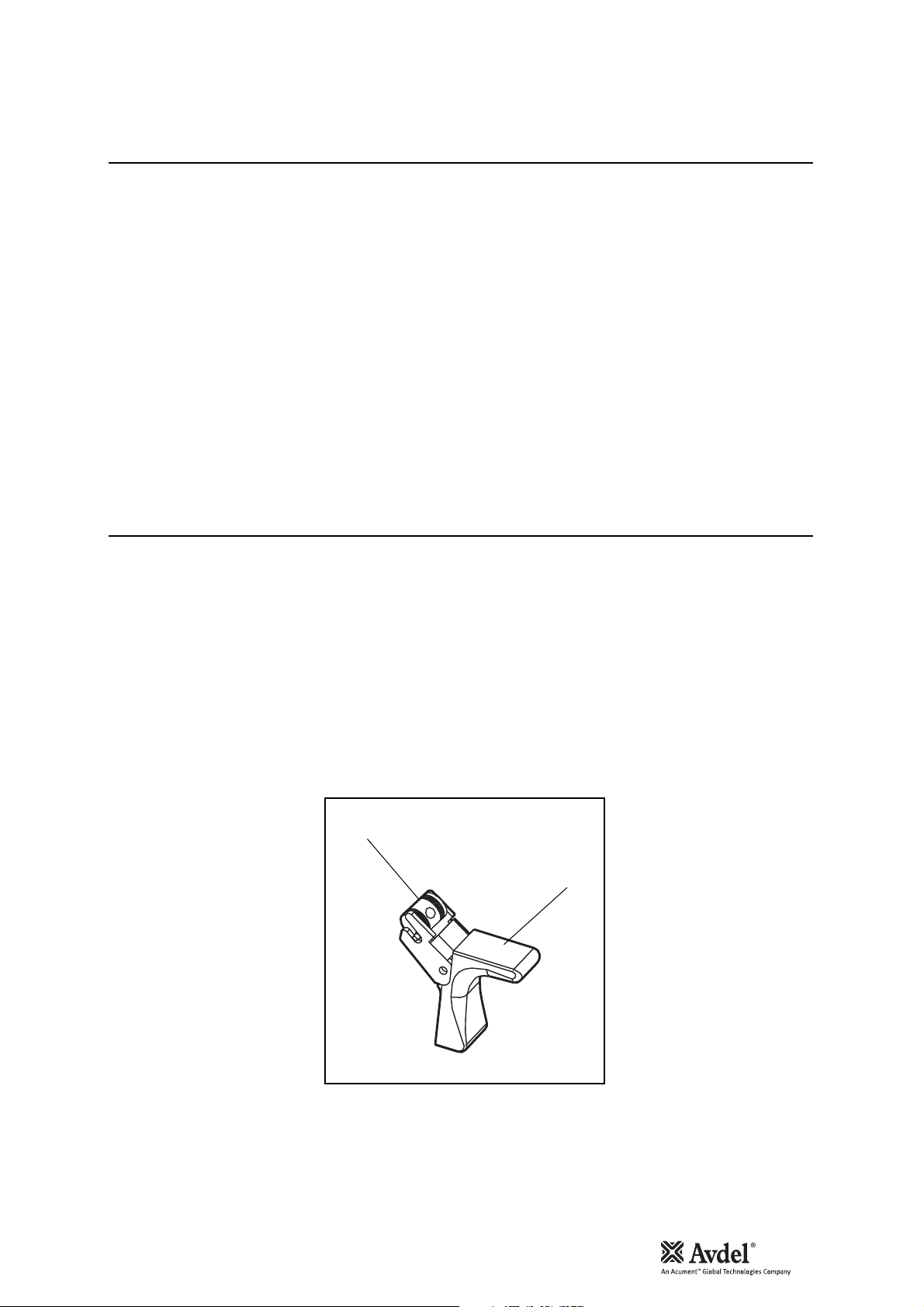
• Using a 4mm pin punch (07900-00158) drive Trigger Pin 46 out and remove Trigger 33.
• Unscrew Trigger Valve 21 using trigger valve extractor (0900-00692).
Assemble in reverse order to Dismantling Instructions noting the following:
• When assembling Trigger 33 the trigger forks locate on the pins each side of the Rotary Valve 38.
• Ensure Rotary Valve 38 is orientated correctly. See illustration below.
Trigger
Item numbers in bold refer to the general assembly drawing and parts list on pages 26 and 27.
23
English
38
33
24
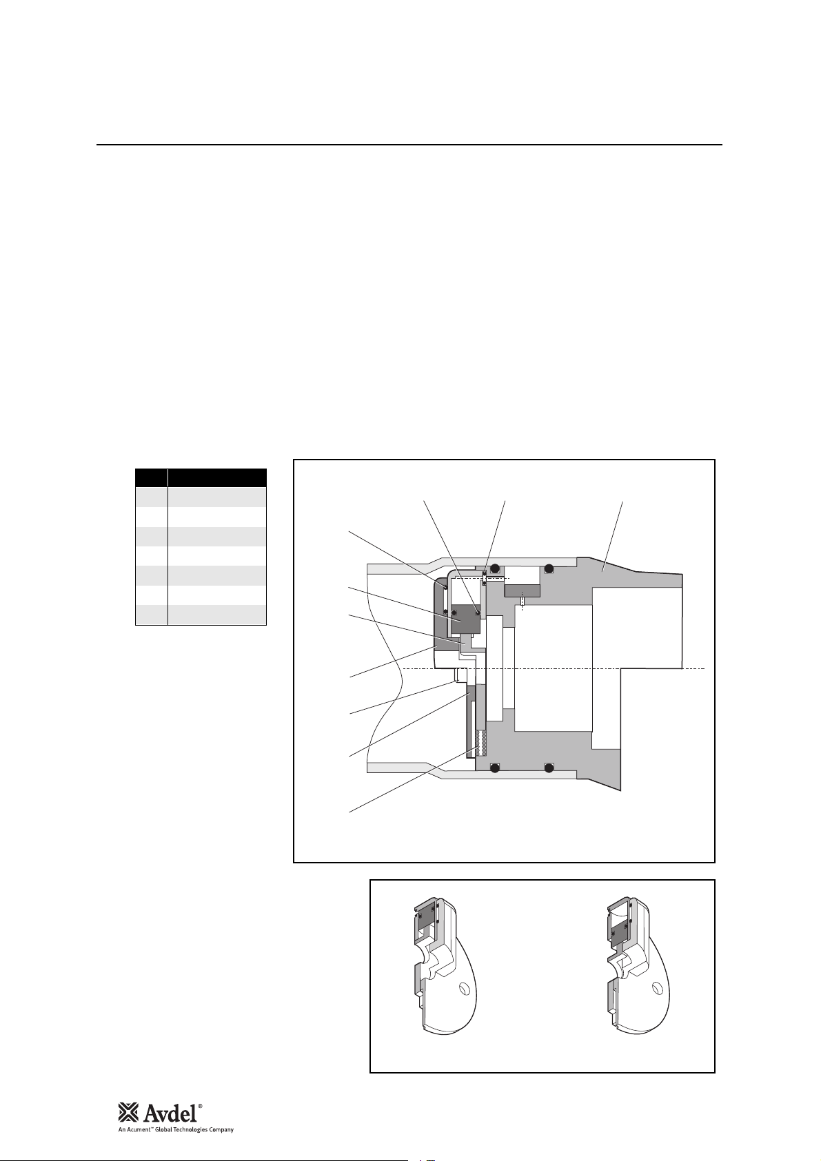
Stop Plate Assembly (71213-03900)
Servicing the Tool
Assembly (see illustration below)
• Place ‘O’ Ring 2 into the recess in Housing 5 retain in position using grease Molykote
®
55.
• Assemble ‘O’ Ring 4 onto Piston 1 and push assembly into Housing 5 making sure it is in as far as it will go.
• Position the slot in Piston 1 parallel to the step face in Housing 5.
• Slide Plate Shut Off 3 into the assembled parts 1, 2, 4, and 5. Retain parts in place using grease Molykote
®
55.
• Place ‘O’ Ring 4 into the recess of Cover Plate 6 retain in position using grease Molykote
®
55.
• Place spring 7 into position locate using the recesses in both Plate Shut Off 3 and Bottle Adaptor Assembly 32*.
• Position the above assembled parts onto Bottle Adaptor Assembly 32*.
• Secure in position using two Screws 89*.
*see pages 26 and 27.
1 PISTON
2 ‘O’ RING
3 PLATE SHUT OFF
4 ‘O’ RING
5 HOUSING
6 COVER PLATE
7 SPRING
ITEM DESCRIPTION
4
1
3
4
2
32*
89*
5
6
7
CLOSED
OPEN

Notes
25
English
26
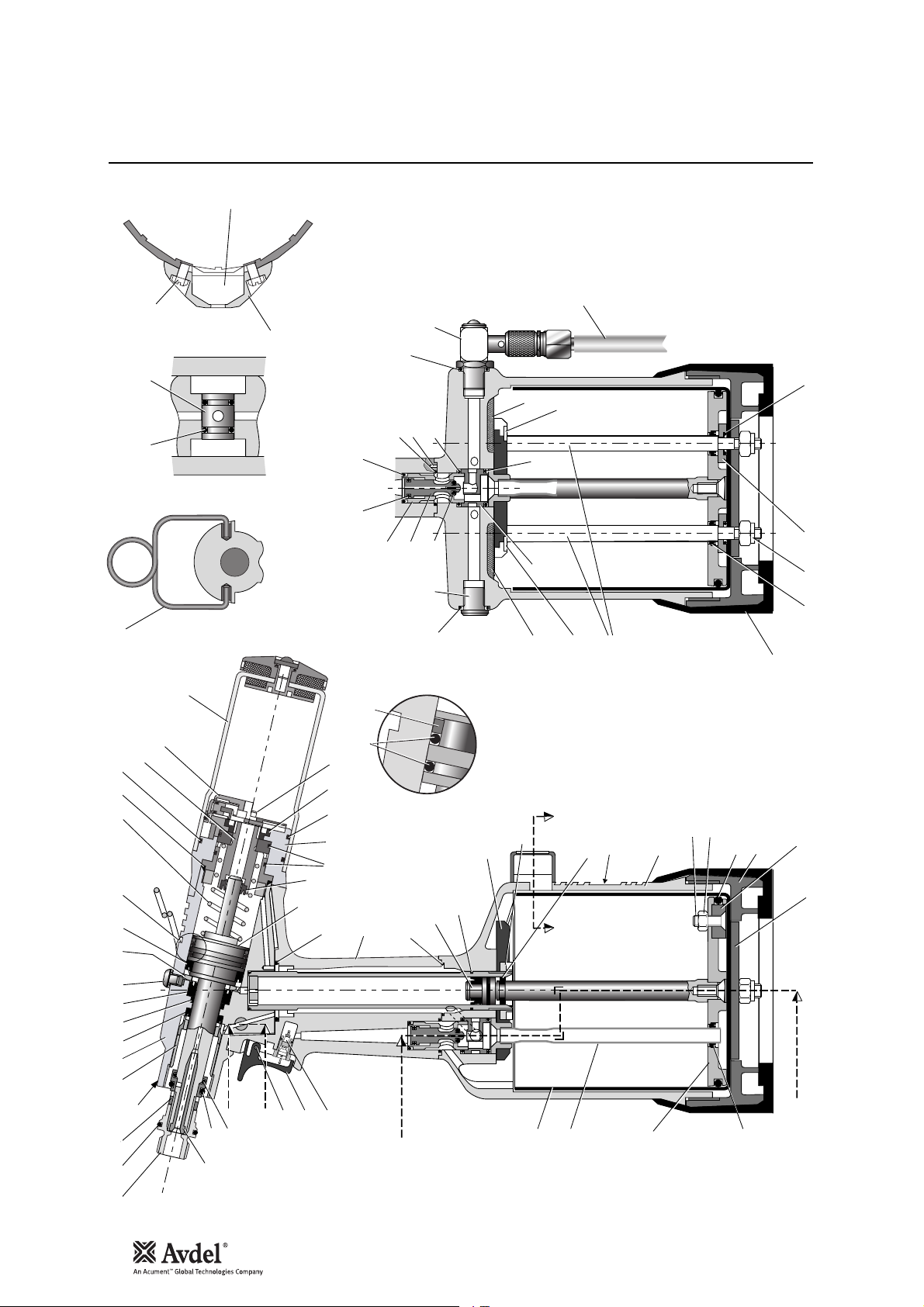
General Assembly of Base Tool 71223-02000
71
H - H
45
28 11
13
91
'X'
74
73
385
104 Assy
35 Assy
25 Assy
72
B - B
Ring
Suspension
8920
50
97 32
9
36
17
7
98
27
18
64 Assy
99
4
24
14
Assy 59
17
62 Assy
14
96
22
4
16
63 Assy
Detail 'X'
44
39
53
14
53
34
76
HH HH
76
23
51
56
49
30
79
80
75
31
A - A
90 67 29 66
48
77
65 Assy
Assy
26
2 8
58
41 12 40 1,6 4352
100
19
42
15
A
B
B
21
46
Assy 33
A
A
37
Assy 61
Assy 57
90

Parts List for 71223-02000
27
English
111111111221111111122112212111231121111
QTY SPARES
SEAL RETAINER
TOP PLATE ASSEMBLY
SUSPENSION RING
TRIGGER PIN
RUBBER BOOT
LABEL
RETAINING NUT
GUIDE RING
SEAL HOUSING
SILENCER
TIE ROD
PNEUMATIC PISTON ASSEMBLY
HEAD ASSEMBLY
VALVE SPOOL ASSEMBLY
TRANSFER TUBE ASSEMBLY
ON/OFF VALVE ASSEMBLY
INTENSIFIER SEAL ASSEMBLY
HANDLE ASSEMBLY
BASE PLATE ASSEMBLY
'O' RING
M6 NYLOC NUT
MODIFIED COUNTER
COUNTER MOULDING
MOULDING RETAINING NUT
SPECIAL M4 SCREW
'O' RING
WASHER
CENTRE POLE MAGNET
M5 X 19 COUNTERSUNK SCREW
M5 NYLOK NUT
SCREW
LIP SEAL
SPRING
'O' RING
'O' RING
'O' RING
71210-02019
71213-02010
71210-02022
71210-02024
71221-02007
71223-02027
71213-02028
71210-03205
71210-02104
71210-02031
71221-02004
71221-03210
71213-03320
71210-03400
71230-03600
71210-03700
71210-03800
71213-02013
71221-02014
07003-00027
07002-00108
71221-20105
71221-20101
71221-20103
71221-20102
07003-00280
07002-00163
07007-01993
71221-20104
07002-00098
07001-00677
07003-00274
07490-03002
07003-00268
07003-00398
07003-00042
43444546484950515253565758596162636465666771727374757677798089909196979899
1
VALVE BODY
LABEL BOOK SYMBOL
TOOL INSTRUCTION MANUAL
STOP PLATE ASSEMBLY
71210-03401
07007-01503
07900-00842
71213-03900
100
103
104
112211111113112211111211112111111111111
QTY SPARES
M5x5 HEX SOCKET BUTTON HD BLEED SCREW
LIP SEAL
'O' RING
'O' RING
M5 BONDED SEAL
'O' RING
LIP SEAL
LIP SEAL
LIP SEAL
'O' RING
'O' RING
'O' RING
'O' RING
'O' RING
'O' RING
'O' RING
'O' RING
'O' RING
TRIGGER VALVE
1/8" BSP PLUG
6" FLEXIBLE HOSE
3mm DIAx10mm SPIROL PIN
STEM COLLECTOR BOTTLE ASSEMBLY
BEARING TAPE - PISTON ROD
BEARING TAPE - PISTON
'O' RING
SEALING WASHER
BODY MACHINED
BASE COVER
BOTTLE ADAPTOR ASSEMBLY
TRIGGER ASSEMBLY
VALVE SEAT
END CAP ASSEMBLY
HEAD PISTON
07001-00405
07003-00333
07003-00127
07003-00189
07003-00194
07003-00271
07003-00273
07003-00274
07003-00341
07003-00277
07003-00278
07003-00281
07003-00204
07003-00287
07003-00288
07003-00342
07003-00310
07003-00415
07005-00088
07005-01274
07008-00010
07007-00224
71213-03800
71213-02021
71213-02022
07003-00416
71221-02006
71223-02001
71221-02002
71213-03000
71213-02008
71210-02009
71213-02025
71223-02121
71223-02000 PARTS LIST * These are minimum recommended levels of spares based on regular servicing
010204050607080911121314151617181920212223242526272829303132333435363738394041
ITEM PART Nº DESCRIPTION ITEM PART Nº DESCRIPTION
CYLINDER LINER
ROTARY VALVE
CLAMP NUT
LOCKNUT
71221-02008
71213-02012
71210-02014
71210-02103
1
JAW SPREADER HOUSING
VACUUM SLEEVE
71210-02101
71220-02102
42
28
Priming
Priming is ALWAYS necessary after the tool has been dismantled and prior to operating. It may also be necessary to restore the full stroke
after considerable use, when the stroke may be reduced and fasteners are not fully placed by one operation of the trigger.
The recommended oil for priming is Hyspin®VG32 available in 0.5 litre (part number 07992-00002) or one gallon containers (part number
07992-00006). Please see safety data below.
First Aid
SKIN:
Wash thoroughly with soap and water as soon as possible. Casual contact requires no immediate attention. Short term contact requires no
immediate attention.
INGESTION:
Seek medical attention immediately. DO NOT induce vomiting.
EYES:
Irrigate immediately with water for several minutes. Although NOT a primary irritant, minor irritation may occur following contact.
Fire
Flash point 232°C. Not classified as flammable.
Suitable extinguishing media: CO
2
, dry powder, foam or water fog. DO NOT use water jets.
Environment
WASTE DISPOSAL: Through authorised contractor to a licensed site. May be incinerated. Used product may be sent for reclamation.
SPILLAGE: Prevent entry into drains, sewers and water courses. Soak up with absorbent material.
Handling
Wear eye protection, impervious gloves (e.g. of PVC) and a plastic apron. Use in well ventilated area.
Storage
No special precautions.
To enable you to follow the priming procedure opposite, you will need to obtain a priming kit:
Oil Details
Hyspin®VG 32 Oil Safety Data
Priming Kit
PRIMING KIT : 07900-00688
PART Nº DESCRIPTION
07900-00351 3mm ALLEN KEY
07900-00700 PRIMING PUMP
07900-00224 4mm ALLEN KEY
07900-00698 STOP NUT
07900-00734 STOP NUT - MAXLOK
®

Priming Procedure
Priming
IMPORTANT
DISCONNECT THE TOOL FROM THE AIR SUPPLY OR SWITCH OFF AT VALVE 55.
REMOVE NOSE ASSEMBLY OR SWIVEL HEAD COMPONENTS.
All operations should be carried out on a clean bench, with clean hands in a clean area.
Ensure that the new oil is perfectly clean and free from air bubbles.
Care MUST be taken at all times, to ensure that no foreign matter enters the tool, or serious damage may result.
• Switch OFF air supply at ON/OFF Valve Assembly 62.
• Remove all nose equipment. (see page 8)
• Remove Bleed Screw 1 and Bonded Seal 6.
• Invert tool over suitable container, switch ON air supply at ON/OFF Valve Assembly 62 and actuate tool.
• Residual oil in the tools hydraulic system will empty through bleed screw orifice.
CARE SHALL BE TAKEN TO ENSURE THAT THE BLEED HOLE IS NOT DIRECTED TOWARDS THE OPERATOR OR OTHER
PERSONNEL.
• Switch air supply OFF at ON/OFF Valve Assembly 62.
• Screw priming pump (07900-00700) into bleed screw port, utilising Bonded Seal 6.
• Actuate Priming Pump by pressing down and releasing several times until resistance is evident and the Head Piston starts to move
rearward.
ENSURE PUMP IS KEPT ‘SQUARE’ TO BLEED SCREW PORT DURING PRIMING OPERATION TO PREVENT BREAKAGE OF BLEED
NIPPLE ON PRIMING PUMP.
• Remove the Priming Pump, surplus oil will expel from bleed screw port.
• Replace the Bleed Screw 1 together with Bonded Seal 6.
• Switch ON air supply at ON/OFF Valve Asembly 62.
• Check that the stroke of the Head Piston reaches specification. If not repeat above procedure.
• Switch OFF air supply and refit nose equipment. (see page 8).
Item numbers in bold refer to the general assembly drawing and parts list on pages 26 and 27.
29
English

30
† Page 17 if a swivel head is used instead of a nose assembly.
Item numbers in bold refer to the general assembly drawing and parts list on pages 26 and 27.
SYMPTOM POSSIBLE CAUSE REMEDY PAGE REF
Other symptoms or failures should be reported to your local Avdel authorised distributor or repair centre.
Symptom Possible Cause Remedy Page Ref
Fault Diagnosis
More than one Air leak Tighten joints or replace components
operation of the Insufficient air pressure Adjust air pressure to within specification 5
trigger needed to Worn or broken jaws Fit new jaws 8
place fastener Low oil level or air in oil Prime tool 28 and 29
Build up of dirt inside the nose assembly Service nose assembly 8†
Tool will not grip Worn or broken jaws Fit new jaws 8 to 12
stem of fastener Build up of dirt inside the nose assembly Service nose assembly 8
Loose jaw housing Tighten against locking ring 8
Weak or broken spring in nose assembly Fit new spring 8 to 12
Incorrect component in nose assembly Identify and replace 9 to 12
Jaws will not release Build up of dirt inside the nose assembly Service nose assembly 8†
broken stem of Jaw housing, nose tip or nose casing
fastener not properly seated Tighten nose assembly 9 to 12
Weak or broken spring in nose assembly Fit new spring 9 to 12
Air or oil leak Tighten joints or replace components
Low oil level or air present in oil Prime tool 28 and 29
Cannot feed next Broken stems jammed inside tool Empty stem collector 7
fastener Check jaw spreader is correct 9 to 12
Adjust air pressure to within specification 5
Slow cycle Low air pressure Adjust air pressure to within specification 5
Build up of dirt inside the nose assembly Service nose assembly 8†
Tool fails to operate No air pressure Connect and adjust to within specification 5
Damaged Trigger Valve 21 Replace 23
Fastener fails to break Insufficient air pressure Adjust air pressure to within specification 5
Fastener outside tool capability Use more powerful Genesis tool
Contact Avdel
Low oil level or air present in oil Prime tool 28 and 29

Declaration of Conformity
We, Avdel UK Limited, Watchmead Industrial Estate, Welwyn Garden City, Herts, AL7 1LY
declare under our sole responsibility that the product:
Model nG3
Serial No. ................................................
to which this declaration relates is in conformity with the following standards:
EN ISO 12100 - parts 1 & 2
BS EN ISO 8662 - part 6 BS EN ISO 11202
BS EN ISO 3744 BS EN 982
ISO EN 792 part 13 - 2000 BS EN 983
following the provisions of the Machine Directive 98/37/EC
This box contains a power tool which is in
conformity with Machines Directive
98/37/EC. The ‘Declaration of Conformity’ is
contained within.
A. Seewraj - Product Engineering Manager - Automation Tools
Date of issue
31
English


33
Règles de sécurité 34
Caractéristiques de l’outil
Caractéristiques de l'outil 35
Dimensions de l’outil 35
Utilisation prévue
Gamme de fixations 36
Numérotation des pièces 36
Mise en service
Alimentation pneumatique 37
Procédure d’utilisation 37
Équipement
Instructions de montage 38
Instructions d’entretien 38
Nez 39-42
Type 1 Standard 39
Nez Avseal®II 40
Type 2 Accès limité 41
Type 3 Aerospace 41
Type 4 Monobolt®- allongé 42
Type 5 Avtainer
®
42
Type 6 Monobolt®- Interlock
®
42
Accessoires
Déflecteur de tiges 43
Préparation de l'outil de base en vue d'une utilisation 43
avec le déflecteur de tiges
Rallonge 43
Ejecteur lateral 44
Capacité de tête pivotante et droite 44
Préparation de l'outil de base en vue d'une utilisation 45
à angle droit et droite
Capacité de tête pivotante à angle droit 45
Instructions de montage des têtes pivotantes 46
Instructions d’entretien des têtes pivotantes 47
Composants constants 47
Entretien de l’outil
Journalier / hebdomadaire 48
Graisse au bisulfure de Molybdène EP 3753 48
informations de sécurité
Informations de sécurité, graisse Molykote
®
55m 49
Informations de sécurité, graisse Molykote®111 49
Kit d’entretien 50
Entretien 50
Equipement de pose 50
Démontage de l'outil 51
Ensemble tête 51
Ensemble piston pneumatique 52
Soupape à air 52
Valve rotative 53
Gâchette 53
Ensemble plaque de butée (71213-03900) 54
Assemblage général de l’outil de base
Assemblage général 56
Liste de pièces 57
Plein d’huile
Huile recommandée 58
Informations de sécurité, huile Hyspin
®
VG 32 58
Kit de plein d’huile 58
Procédure de plein d’huile 59
Diagnostic des pannes
Symptôme, cause possible & remède 60
Avdel UK Limited poursuit une politique de développement et d'amélioration continue et se réserve le droit de modifier les caractéristiques de ses produits sans préavis.
GARANTIE LIMITEE.
Les termes de la garantie limitée Avdel confirment l'engagement de cette dernière
vis-à-vis de produits exempts de vices de fabrication et de matériaux et ce dans des
conditions d'utilisation normales. Cette garantie limitée tient compte des restrictions
suivantes : (1) le produit sera installé, entretenu et exploité conformément à la
documentation et au mode d'emploi y afférents et (2) Avdel aura confirmé le vice
signalé après inspection et tests. La garantie limitée Avdel susdite est valable douze
(12) mois, à compter de la livraison du produit par Avdel à l'acheteur direct du produit
Avdel. Le renvoi des marchandises défectueuses constitue le recours exclusif en cas
de manquement à la garantie susdite ; celles-ci seront remplacées ou remboursées au
prix d'achat, la décision en la matière appartenant à Avdel. LA GARANTIE LIMITEE
EXPRESSE ET LE RECOURS SUSDITS SONT EXCLUSIFS ET SE SUBSTITUENT A TOUS
AUTRES GARANTIES ET RECOURS. AVDEL DESAVOUE ET EXCLUT SPECIFIQUEMENT
TOUTE GARANTIE IMPLICITE DE QUALITE, D'APTITUDE A L'EMPLOI ET DE
COMMERCIABILITE DU PRODUIT.
Sommaire
Français

34
Règles de sécurité
1 Ne pas employer à d'autres usages que celui prévu.
2 Ne pas utiliser avec cet outil / cette machine d'autres matériels que ceux recommandés et fournis par Avdel UK Limited.
3 Toute modification apportée par le client à l'outil ou à la machine, aux équipement, aux accessoires ou à tout autre matériel fourni par
Avdel UK Limited ou ses représentants relève de la seule et entière responsabilité du client. Avdel UK Limited donnera volontiers son avis
sur toute modification envisagée.
4 L'outil ou la machine doivent être maintenus en permanence en état de fonctionner sans danger et leur bon état et fonctionnement doivent être
vérifiés à intervalles réguliers par un personnel compétent et ayant reçu la formation adéquate. Toute opération de démontage ne doit être
entreprise que par des personnes formées aux procédures Avdel UK Limited. Ne pas démonter cet outil/cette machine avant d'avoir consulté
les instructions de maintenance. Prière de consulter Avdel UK Limited pour ce qui concerne vos besoins en formation.
5 L'outil ou la machine doivent à tout moment être utilisés conformément à la législation d'hygiène et de sécurité conforme aux règlements
du Ministère du Travail en application de l'article R233-69 du code du travail. Toute question relative à la bonne utilisation de l'outil ou de la
machine et à la sécurité de l'opérateur doit être adressée à Avdel UK Limited.
6 Il appartient au client d'expliquer à chaque opérateur les précautions à respecter lors de l'utilisation de l'outil ou de la machine.
7 Toujours débrancher le tuyau d'air du raccord d'arrivée de l'outil ou de la machine avant tout réglage, montage ou démontage d'un
ensemble de nez.
8 Ne pas actionner un outil/une machine orientés vers une/des personne(s) ou l’opérateur.
9 L’opérateur veillera à adopter une position équilibrée et stable avant d’utiliser l’outil/la machine.
10 S’assurer que les orifices de mise à l’atmosphère ne viennent pas à être obstrués ou masqués.
11 La pression de service ne doit pas dépasser 7 bars.
12 Ne pas utiliser l’outil si celui-ci n’est pas muni d’un équipement complet ou d’une tête pivotante, à moins d’une consigne contraire explicite.
13 L’on veillera à faire en sorte que les tiges usagées ne risquent pas de constituer un danger.
14 La fonction d’élimination de l’air DOIT être désactivée à l’aide de la gâchette avant d’ôter le vase récupérateur de tiges qui DOIT être vidé
lorsqu’il est à moitié plein.
15 L'outil NE DOIT PAS être utilisé lorsque le vase de récupération des tiges est enlevé.
16 Si l’outil nG3 est muni d’un déflecteur de tiges, l’on veillera à faire pivoter le déflecteur de manière à ce que l’ouverture soit tournée du
côté opposé à l’opérateur et, le cas échéant, à des personnes travaillant à proximité.
17 Lors de l'utilisation de l'outil, l'opérateur et les personnes se trouvant à proximité doivent impérativement porter des lunettes de sécurité
pour se protéger contre l'éjection des fixations en cas de pose ‘en l'air’. Nous recommandons le port de gants en cas de présence
d'arêtes ou d'
angles vifs sur l'application.
18 Veiller à ne pas laisser des vêtements amples, cravates, cheveux longs, chiffons de nettoyage, etc. se prendre dans les parties mobiles
de l'outil. L'outil doit être maintenu sec et propre pour donner la meilleure prise.
19 Lors du transport de l'outil, éloigner les mains de la gâchette ou du levier pour éviter un déclenchement intempestif de l'outil.
20 Tout contact excessif avec de l’huile hydraulique doit être évité. Veiller à bien se laver pour éviter tout risque d’éruption cutanée.
21 Les données C.O.S.H.H. de sécurité et d'hygiène professionnelle se rapportant aux fluides hydrauliques et lubrifiants sont disponibles sur
demande auprès du fournisseur de l'outil.
Toute personne participant à l'installation, à l'utilisation ou à l'entretien de cet outil doit lire attentivement ce manuel.

Caractéristiques de l'outil
Spécifications
35
Pression pneumatique Minimum - Maximum 5 à 7 bars
Volume d’air libre nécessaire à 5,5 bars 4,3 litres
Course Minimum 26 mm
Force de traction à 5,5 bars 12,9 kN
Cycle de pose Approximativement 1,2 seconde
Niveau sonore 75 dB(A)
Poids Equipement de pose inclus 2.25 kg
Vibrations Inférieures à 2,5 m/s
2
Dimensions en millimètres
Dimensions de l’outil
Remarque : tiges à vase de
récupération; version courte est un
accessoire référence 71213-03810
Français
ECORCHE DU RECUPERATEUR DE
TIGES A VASE DE RECUPERATION ; VERSION COURTE

36
Utilisation prévue
Le nG3 est un outil oléo-pneumatique
destiné à la pose à cadence rapide de
rivets à rupture de tige Avdel
®
, qui
convient parfaitement au travail en lots
ou en chaîne continue pour une grande
diversité d’applications dans tous les
secteurs industriels. Les fixations qu’il
permet de poser sont indiquées cicontre.
L'outil comporte un dispositif à
dépression réglable qui sert à maintenir
la fixation et à récupérer facilement les
tiges brisées quelle que soit l'orientation
de l'outil.
Un outil complet se compose de
trois éléments individuels fournis
séparément. Voir le schéma cidessous.
L’EQUIPEMENT DE POSE DOIT
ETRE INSTALLE CONFORMEMENT
AUX INSTRUCTIONS DE LA PAGE
38.
La référence de l’outil de base reste la même, quel que soit l’équipement ou le nez monté. Voir l’assemblage général pages 56 et
57. Pour monter une tête pivotante, il est nécessaire d’adapter le même outil de base. Pour plus de détails, voir pages 44 et 45.
La référence du nez correspond à une fixation particulière. En cas de difficulté d'accès,
il existe certains nez allongés. Voir le tableau de la page 41 et 42.
L’équipement unique permet de poser des fixations non aéronautiques en choisissant simplement le
modèle voulu dans la gamme de nez de type 1. Il existe d’autre équipements pour les applications à accès
limité et pour les fixations aéronautiques et spéciales. Voir le tableau de la page 41. Un équipement peut
être remplacé par une tête pivotante (voir pages 44 à 45). Dans ce cas, le nez fait partie de la tête
pivotante.
Gamme de fixations
Numérotation des pièces
NOM DE LA
FIXATION
®
AVEX
®
STAVEX
AVINOX® II
AVIBULB
BULBEX
AVDEL® SR
MONOBOLT
INTERLOCK
AVTAINER
MBC/LC
AVSEAL® II
Q
T
CHERRYMATE™
KLAMPTITE™
KLAMPTITE™KTR
ETR
T-LOK
AVDEL
®
MBC
™ RIVET
™ RIVET
®
®
®
®
®
®
®
®
DIMENSION DE LA FIXATION ( )
3 3.2 4.0 4.3 4.8 5 5.2 6 6.4 6.5 7 8 9 9.5 10
– 1/8 5/32 – 3/16 – – – 1/4 – – – – 3/8 –
MM
Pouces
1
2
ÉQUIPEMENT
71210-15000
2
OUTIL DE BASE
71223-02000
1
3
NEZ
voir note 3
3
*AJOUTER LES 3 CHIFFRES
TROUVES DANS LA DERNIERE
COLONNE D'UN DES TABLEAUX
DE NEZ DES PAGES 39 - 42.
POUR LES OUTILS A TETES
PIVOTANTES, UTILISER LES
TABLEAUX DES PAGES 44 - 45.
++=
1
2
3
OUTIL COMPLET
71223-00 . . .
*

37
Tous les outils fonctionnent à l'air comprimé, à une pression optimale de 5,5 bars. Nous préconisons l'utilisation de régulateurs de pression
et de systèmes de filtration sur le circuit d'alimentation pneumatique. Ces appareils doivent être montés à 3 mètres au plus de l'outil (voir le
schéma ci-dessous) afin d'assurer à l'outil une durée de vie maximum et une maintenance minimum.
Les flexibles d'alimentation en air doivent être compatibles avec une pression de service active minimum équivalente à 150% de la pression
maximum produite par le système ou de 10 bars, selon la plus élevée de ces valeurs. Ces flexibles doivent résister à l'huile, avoir une paroi
extérieure résistant à l'abrasion, et ils doivent être armés si les conditions d'utilisation présentent un risque de détérioration. Tous les
flexibles d'air DOIVENT IMPERATIVEMENT avoir un diamètre intérieur minimum de 6,4 millimètres.
• Veiller à bien monter l’équipement ou la tête pivotante qui
conviennent à la fixation.
• Raccorder l’outil à l’alimentation pneumatique.
• Introduire la tige de la fixation dans le nez de l’outil. Dans le cas
d’un équipement, la fixation doit rester maintenue par le système à
dépression.
• Présenter sur l'application l'outil portant la fixation de telle sorte
que cette dernière pénètre bien d'équerre dans le trou de
l'application.
• Actionner à fond la gâchette. Le cycle de l'outil sertit la fixation et
s'il s'agit d'un équipement standard, la tige cassée est projetée
vers l'arrière de l'outil, dans le vase de récupération.
• Pour le retirer, faire légèrement pivoter/tirer sur le vase de
récupération. Avant de retirer le vase de récupération, soulever la
gâchette pour couper l'alimentation en vide.
Mise en service
Alimentation pneumatique
Procédure d’utilisation
• On minimisera la consommation d'air en soulevant la 'gâchette' pour
couper l'alimentation en vide dans les cas où une période d'inutilisation
de l'outil risque de se prolonger.
Français
N’utilisez pas l’outil lorsque
le vase de récupération des
tiges est enlevé
(SERT LORS DE LA MAINTENANCE DES APPAREILS
ROBINET D'ARRET
DE FILTRATION, REGULATION ET D'HUILAGE)
3 METRES MAXIMUM
LUBRIFICATION À L'AIR
AUTORISÉE
PIQUAGE
SUR L'ALIMENTATION
PRINCIPALE
10
8
6
12
4
14
2
16
0
POINT DE PURGE
DE L'ALIMENTATION
PRINCIPALE
REGULATEUR DE PRESSION
ET FILTRE (A PURGER QUOTIDIENNEMENT)
Soulever la gâchette
pour couper
l'alimentation
pneumatique.

38
Equipement
*Elément inclus dans le kit d'entretien nG3. Voir la liste complète page 50.
Instructions de montage
IMPORTANT
Les équipements NE COMPRENNENT PAS les nez. Ceux-ci doivent être commandés séparément.
Un outil complet doit toujours être équipé de l’équipement et du nez qui conviennent à votre fixation et qui doivent être commandés
séparément ; se reporter aux tableaux des ‘NEZ’ des pages 39 à 42.
Si l'application ne présente pas de difficulté d'accès, utiliser les nez de type 1, sauf dans le cas des fixations aéronautiques, qui
nécessitent un type 3, et des fixations Avtainer(r), qui demandent un type 5.
Les dimensions ‘A’ et ‘B’ des tableaux de nez suivants vous aideront à évaluer la compatibilité d’un nez en particulier.
Vérifier également que le carter de nez ne limite pas l'accès à votre application. Si c'est le cas, il existe des nez de type 2 pour
certaines fixations. Consulter le tableau de la page 41.
Il est impératif de n'utiliser l'outil qu'avec un équipement et un nez compatibles avec la fixation.
Le nez de type 4 peut servir à poser les Monobolt® 1/4 de pouce. Se reporter au tableau de la page 42.
On peut également remplacer les équipements par une tête pivotante pour atteindre des positions plus difficiles. Voir la partie
Accessoires, pages 44 à 47.
Les équipement doivent être entretenus chaque semaine. Il est conseillé de conserver un stock des pièces internes de l'équipement et du nez,
qui doivent être remplacées périodiquement.
Utilisez la clé 07900-00849 (fournie avec l'outil) pour faciliter l'entretien de l'équipement de pose.
• Démonter l'équipement de pose en procédant à l'inverse des instructions de montage.
• Remplacer toute pièce usée ou endommagée.
• Nettoyer les mâchoires et vérifier leur usure.
• Vérifier que ni le Porte-mâchoires, ni le Guide de Ressort Avant ne sont déformés.
• Vérifier que le ressort 7 n'est pas déformé.
• Assembler selon les instructions ci-dessus.
IMPORTANT
Débrancher l'alimentation pneumatique avant de monter ou démonter les équipement.
Les repères en caractères gras indiquent les composants des équipements dans les 5 tableaux de nez.
• Enduire les mâchoires 4 d'une légère couche de graisse au bisulfure de molybdène*.
• Faire tomber les Mâchoires 4 dans le Carter Porte-mâchoires 3 ou le Boîtier de Mors 9 selon l'équipement utilisé.
• Introduire le Porte-mâchoires 5 dans le Carter Porte-mâchoires 3, ou introduire le Guide de Ressort Avant 10 dans le Boîtier de Mors 9.
• Placer le butoir 6 sur le porte-mâchoires 5.
• Placer le Ressort 7 sur le Carter Porte-mâchoires 5 ou sur le Guide de Ressort Avant 10.
• Visser le Guide de Ressort Arrière 11 dans le Boîtier de Mors 9.
• Monter la Bague de Serrage 8 sur le Carter Guide de l'outil.
• En tenant l'outil pointé vers le bas, visser le Carter Porte-mâchoires ou le Boîtier de Mors assemblé sur le Carter Guide et serrer à la clé*.
• Visser le nez dans le carter de nez 1 et serrer à la clé*.
• Placer le carter de nez 1 sur le carter porte-mâchoires 3, ou dans le Boîtier de Mors 9, et visser sur l'outil, en serrant à la clé*.
Instructions d’entretien

Nez de Type
Equipement
39
Français
NEZ DE
TYPE 1
1
En pouces, puis en millimètres.
2
Nez à formage de tête pour têtes fraisées SEULEMENT.
* OUTRE l'équipement indiqué ci-dessous, il existe
une version extra-longue destinée à la pose du
Monobolt® 1/4 de pouce dans les applications à
accès limité. Voir le tableau des NEZ de type 4.
ÉQUIPEMENT
Réf. 71210-15000
REPERE DESCRIPTION REFERENCE
1 CARTER DE NEZ 07340-00306
2 JOINT TORIQUE 07003-00067
3 CARTER PORTE-MACHOIRES 07340-00304
4 MACHOIRES 71210-15001
5 PORTE-MACHOIRES 07498-04502
6 BUTOIR 71210-05001
7 RESSORT 07500-00418
8 BAGUE DE SERRAGE 07340-00327
FIXATION
®
AVEX
5
5
5
3
Large flange
MONOBOLT
BULBEX
AVINOX® II
T-LOK
AVIBULB
AVDEL® SR
Vis a tête fraisée
INTERLOCK
STAVEX
Bride large
Vis a tête fraisée
Q™ RIVET
CHERRYMATE™
KLAMPTITE™
KTR
KLAMPTITE™
T™ RIVET
Bride large
Bride large
3
3
3
3
®
5
®
3
1
5
3
®
3
1
®
5
3
1
5
3
3
1
3
®
®
5
3
3
3
5
3
1
5
3
3
3
3
3
3
3
3
Bride large
Bride large
4,8
3,3
2,9
4,8
3,3
2,8
3,3
2,8
3,3
3,3
4,1
3,3
4,1
3,3
2,8
3,3
2,8
4,8
3,3
3,3
3,3
2,8
4,8
3,3
4,8
3,3
5,7
5,7
3,3
2,8
3,3
2,8
2,8
3,3
2,8
3,3
2,8
2,8
4,8
3,3
3,3
3,3
3,3
3,3
4,8
4,8
4,8
4,8
6,35
6,35
6,35
6,35
6,65
6,65
6,65
6,65
voir
ci-dessous
…001
…004
…003
…001
…004
…010
…009
…010
…016
…017
…015
…021
…200
…004
…010
…004
…010
…082
…120
…120
…004
…010
…082
…021
…001
…004
…062
…064
…063
…010
…004
…010
…010
…016
…010
…004
…010
…010
…001
…120
…120
…021
…120
…021
…500
…501
…010
…021
…380
…381
…383
…384
…385
…386
…387
…388
1
MATERIAU
Ø
1
/
1
/
1
/
–
/
32
/
32
/
32
/
16
/
16
/
16
/
16
1
/
/
16
/
32
/
16
/
8
/
32
/
16
–
/
16
/
8
/
32
/
16
–
/
8
/
32
/
16
/
16
/
4
/
16
1
/
/
32
/
16
/
16
/
16
1
/
/
32
/
16
/
8
/
32
/
16
1
/
/
16
1
/
/
16
1
/
/
16
1
/
/
16
/
16
/
16
/
16
1
/
1
/
1
/
1
/
3,2
8
3,2
8
3,2
8
3
4,0
4,0
4,0
4,8
4,8
4,8
4,8
6,4
4
4,8
4,0
4,8
3,2
4,0
4,8
4,3
4,8
3,2
4,0
4,8
6
3,2
4,0
4,8
4,8
6,4
4,8
3,2
8
4,0
4,8
4,8
4,8
3,2
8
4,0
4,8
3,2
4,0
4,8
6,4
4
4,8
6,4
4
4,8
6,4
4
4,8
6,4
4
4,8
4,8
4,8
4,8
6,4
4
6,4
4
6,4
4
6,4
4
Alliage díaluminium
Acier
Alliage d’aluminium
Alliage d’aluminium
Alliage d’aluminium
Acier
Alliage d’aluminium
Alliage d’aluminium
Alliage d’aluminium
Acier
Alliage d’aluminium
Alliage d’aluminium
Tous
Alliage d’aluminium
Alliage d’aluminium
Acier inoxydable
Acier inoxydable
Acier inoxydable
Acier
Acier
Acier
Acier
Acier
Acier
Tous
Tous
Tous
Tous
Tous
Tous
Acier
Acier
Acier
Acier
Acier
Acier inoxydable
Acier inoxydable
Acier inoxydable
Tous
Tous
Tous
Tous
Tous
Tous
Tous
Tous
Tous
Tous
Alliage d’aluminium
Alliage d’aluminium
Alliage d’aluminium/Acier
Alliage d’aluminium/Acier
Alliage d’aluminium
Alliage d’aluminium
Alliage d’aluminium/Acier
Alliage d’aluminium/Acier
07340-06401
07340-06501
07340-06601
07348-07001
71210-16050
NEZ (mm)
REFERENCE 'A' 'B'NOM
71210-05002
71210-16070
71210-05002
71210-16070
07381-04701
07381-04701
07340-04800
07490-04401
07612-02001
71210-16020
71210-16070
07381-04701
71210-16070
07381-04701
07498-01401
07340-06201
07340-06201
71210-16070
07381-04701
07498-01401
07612-02001
71210-05002
71210-16070
71220-60001
07381-04701
71210-16070
07381-04701
07381-04701
07340-04800
07381-04701
71210-16070
07381-04701
07381-04701
71210-05002
07340-06201
07340-06201
07612-02001
07340-06201
07612-02001
71220-16060
71220-16061
07381-04701
07612-02001
703-A-25-6TA
703-B-21
703-A-25-6T
703-B-26
743-A-25-8TA
703-B-21
743-A-25-8T
743-B-26
2
2
2
4
5
12,7
12,7
12,7
12,7
12,7
12,7
12,7
12,7
19,0
12,7
12,7
12,7
12,7
12,7
12,7
12,7
12,7
12,7
12,7
12,7
12,7
12,7
12,7
12,7
12,7
12,7
12,7
12,7
12,7
12,7
12,7
12,7
12,7
19,0
12,7
12,7
12,7
12,7
12,7
12,7
12,7
12,7
12,7
12,7
12,7
12,7
12,7
12,7
12,7
12,7
12,7
12,7
12,7
12,7
12,7
12,7
8 7 6 5 4 23 1
61
22,9
REFERENCE DE
L'OUTIL COMPLET :
A
faire précéder de
B
71223-00

40
Equipement
Nez de Type
NEZ
AVSEAL
®
II
NOM
AVSEAL®II
FIXATION
–
–
–
–
–
–
–
–
–
–
–
–
–
–
–
MATÉRIAU
Ø
Alliage standard Al - nez affleuré
6.0
Alliage standard Al - nez allongé 2 mm
6.0
Alliage standard Al. - nez allongé 8 mm
6.0
6.5
Alliage standard Al - nez affleuré
6.5
Alliage standard Al - nez allongé 2 mm
6.5
Alliage standard Al. - nez allongé 8 mm
7.0
Alliage standard Al - nez affleuré
7.0
Alliage standard Al - nez allongé 2 mm
7.0
Alliage standard Al. - nez allongé 8 mm
8.0
Standard & basse pression - nez affleuré
8.0
Standard & basse pression - nez allongé 2 mm
8.0
Standard & basse pression - nez allongé 8 mm
9.0
Alliage basse pression Al - nez affleuré
9.0
Alliage basse pression Al - nez allongé 2 mm
9.0
Alliage basse pression Al - nez allongé 8 mm
ÉQUIPEMENT
Réf. 71210-16100
REPÈRE
DESCRIPTION RÉFÉRENCE
1 07340-00306
CARTER DE NEZ
2 07003-00067
JOINT TORIQUE
3 07340-00304
CARTER PORTE-MÂCHOIRES
MÂCHOIRES
4 71210-16101
PORTE-MÂCHOIRES
5 07498-04502
6 71210-05001
7 07500-00418
BAGUE DE SERRAGE
8 07340-00327
BUTOIR
RESSORT
EQUIPEMENT
71210-16100
71210-16100
71210-16100
71210-16100
71210-16100
71210-16100
71210-16100
71210-16100
71210-16100
71220-16100
71220-16100
71220-16100
71220-16100
71220-16100
71220-16100
ÉQUIPEMENT
Réf. 71220-16100
REPÈRE
DESCRIPTION RÉFÉRENCE
1 07340-00306
CARTER DE NEZ
2 07003-00067
JOINT TORIQUE
3 07612-02003
CARTER PORTE-MÂCHOIRES
4 71220-16120
5 07498-04502
6 07498-03003
7 07500-00418
8 07340-00327
MÂCHOIRES
PORTE-MÂCHOIRES
BUTOIR
RESSORT
BAGUE DE SERRAGE
NEZ (mm)
REFERENCE 'A' 'B'
71210-16104
71210-16108
71210-16112
71210-16114
71210-16115
71210-16116
71210-16105
71210-16109
71210-16113
71220-16102
71220-16103
71220-16104
71220-16105
71220-16106
71220-16107
12.7
12.7
12.7
12.7
12.7
12.7
12.7
12.7
12.7
14.3
14.3
14.3
12AF
12AF
12AF
L'OUTIL COMPLET :
A
B
voir
ci-dessous
… 407
2.5
… 408
5.4
… 409
11.4
… 413
2.5
… 414
5.4
… 415
11.4
… 410
2.5
… 411
5.4
… 412
11.4
… 413
2.5
… 414
5.4
… 415
11.4
… 430
3.3
… 431
5.4
… 432
11.4
RÉFÉRENCE DE
faire précéder
de 71223-00.
8 7 6 5 4 23 1
22.9
61

41
Français
Equipement
Nez de Type
Remarque : les repères 9 et 10 ne sont pas nécessaires pour l’assemblage des types de nez 2 ou 3 sur l’outil de base nG3 (71223-02000).
Remarque : les repères 9 et 10 ne sont pas nécessaires pour l’assemblage des types de nez 2 ou 3 sur l’outil de base nG3 (71223-02000).
NEZ DE
TYPE 2
EQUIPEMENT
Réf. 71210-15200
REPERE DESCRIPTION REFERENCE
1
2
3
CARTER PORTE-MACHOIRES
4
5
6
7
8
9 CARTER GUIDE 21210-02101
10 JOINT TORIQUE 07003-00277
CARTER DE NEZ
JOINT TORIQUE
MACHOIRES
PORTE-MACHOIRES
BUTOIR
RESSORT
BAGUE DE SERRAGE
07340-02804
07003-00067
07340-00304
71210-15001
07498-04502
71210-05001
07500-00418
07340-00327
FIXATION
1
MATERIAU
Ø
1
®
AVEX
BULBEX
T-LOK
STAVEX
AVIBULB
E.T.R
1
En pouces, puis en millimètres.
LES NEZ DE TYPE 2 SONT ALLONGES
POUR PERMETTRE D’ACCEDER A
DES APPLICATIONS QUE LES NEZ
DE TYPE 1 NE PEUVENT ATTEINDRE.
/
8
1
/
8
5
/
32
5
/
32
3
/
16
3
/
16
5
®
/
32
3
/
16
®
–
3
/
16
1
®
/
8
5
/
32
3
/
16
1
/
8
5
/
32
3
/
16
1
®
/
8
5
/
32
–
Alliage d’aluminium
3.2
Acier
3.2
Alliage d’aluminium
4.0
Acier
4.0
Alliage d’aluminium
4.8
Acier
4.8
Alliage d’aluminium
4.0
Alliage d’aluminium
4.8
Acier
4.3
Acier
4.8
Acier
3.2
Acier
4.0
Acier
4.8
Acier inoxydable
3.2
Acier inoxydable
4.0
Acier inoxydable
4.8
Acier
3.2
Acier
4.0
Acier/laiton
5.2
8 7 6 5 4239 10
NEZ (mm)
REFERENCE 'A' 'B'NOM
07340-02805
07340-02806
07340-02806
07340-02807
07340-02807
07340-07301
07340-02806
07340-02807
07241-07101
07241-07101
07340-02806
07340-02807
07340-02807
07340-02806
07340-02807
07340-02807
07340-02806
07340-02807
07340-02807
A
B
12.95
9.5
11.4
9.5
11.4
9.5
10.0
12.7
10.0
12.7
11.8
12.7
11.4
9.5
10.0
12.7
10.0
12.7
10.0
12.7
11.4
9.5
10.0
12.7
10.0
12.7
11.4
9.5
10.0
12.7
10.0
12.7
11.4
9.5
10.0
12.7
10.0
12.7
REFERENCE DE
L'OUTIL COMPLET :
faire précéder de
71223-00.
58.3
1
voir
ci-dessous
…002
…008
…008
…014
…014
…018
…008
…014
…121
…121
…008
…014
…014
…008
…014
…014
…008
…014
…014
22.9
NEZ DE
LES NEZ DE TYPE 3 SONT SPECIALEMENT DESTINES AUX
FIXATIONS AERONAUTIQUES LISTEES CI-DESSOUS
TYPE 3
EQUIPEMENT
Réf. 71210-15300
REPERE DESCRIPTION REFERENCE
1 07344-02001
2 07003-00067
3 07340-00304
CARTER PORTE-MACHOIRES
4 71210-15001
5 07498-04502
6 71210-05001
7 07500-00418
8 07340-00327
9 71210-02101
10 07003-00277
9 10
CARTER DE NEZ
JOINT TORIQUE
MACHOIRES
PORTE-MACHOIRES
BUTOIR
RESSORT
BAGUE DE SERRAGE
CARTER GUIDE
JOINT TORIQUE
8 7 6 5 423
FIXATION
1
Ø
1
®
/
3.2
AVDEL
®
MBC
MBC L/C
1
En pouces, puis en millimètres.
8
1
/
3.2
8
1
/
3.2
8
5
/
4.0
32
5
/
4.0
32
5
/
4.0
32
3
/
4.8
16
3
/
4.8
16
1
/
3.2
8
5
/
4.0
32
3
/
4.8
16
1
®
/
3.2
8
5
/
4.0
32
3
/
4.8
16
56.3
1
MATERIAU
Alliage d’aluminium
Alliage d’aluminium
Acier inoxydable
Alliage d’aluminium
Alliage d’aluminium
Acier inoxydable
Alliage d’aluminium
Alliage d’aluminium
Tous
Tous
Alliage d’aluminium
Tous
Tous
Alliage d’aluminium
O
Surdimensionnée
22.9
71210-16030
O
71210-16031
71210-16032
71210-16033
O
71210-16034
71210-16035
71210-16036
O
71210-16037
07340-06701
07340-06801
07340-06901
07344-04701
07344-04701
07344-04701
REFERENCE 'A' 'B'NOM
B
NEZ (mm)
12.7
12.7
12.7
12.7
12.7
12.7
12.7
12.7
12.7
12.7
12.7
12.7
12.7
12.7
A
L'OUTIL COMPLET :
voir
ci-dessous
2.5
…283
2.5
…284
3.3
…285
2.5
…288
2.5
…289
3.3
…290
2.5
…293
2.5
…294
4.8
…300
5.0
…305
5.1
…310
4.6
…320
4.6
…320
4.6
…320
REFERENCE DE
faire précéder de
71223-00.

42
Nez de Type
Equipement
NEZ DE
TYPE 4
ÉQUIPEMENT
REPERE DESCRIPTION REFERENCE
1 07498-00501
2 07003-00067
9 07498-00502
4 07497-03002
CARTER DE NEZ
JOINT TORIQUE
BOITIER DE MORS
MACHOIRES
11 7 10 4298
NEZ DE
TYPE 5
ÉQUIPEMENT
REPERE DESCRIPTION REFERENCE
1 07498-00501
2 07003-00067
9 07498-00801
4 07220-02302
10 07498-00803
CARTER DE NEZ
JOINT TORIQUE
BOITIER DE MORS
MACHOIRES
GUIDE DE RESSORT AVANT
FIXATION
1
MATERIAU
Ø
1
®
/
6,4
Tous
MONOBOLT
1
En pouces, puis en millimètres.
4
Réf. 71220-15400
REPERE DESCRIPTION REFERENCE
GUIDE DE RESSORT AVANT
10 07498-00507
7 07500-02005
GUIDE DE RESSORT ARRIERE
11 07498-00503
8 07340-00327
BAGUE DE SERRAGE
1
AVTAINER
1
®
En pouces, puis en millimètres.
RESSORT
FIXATION
1
Ø
3
/
9,6
8
98.5
MATERIAU
Acier
Réf. 71220-15500
REPERE DESCRIPTION REFERENCE
7 07500-02005
GUIDE DE RESSORT ARRIERE
11 07498-00503
8 07340-00327
ADAPTATEUR D'EJECTION LATERALE
12 07498-00900
ENS. ÉCROU D'ARRÊT OBTURATEUR DE VIDE
13 71233-20200
BAGUE DE SERRAGE
RESSORT
NEZ (mm)
REFERENCE 'A' 'B'NOM
71220-16021
A
B
MONTE SUR CET ÉQUIPEMENT
LONG, LE NEZ DE TYPE 4
PERMET DE POSER LES
FIXATIONS MONOBOLT® 1/4
DE POUCE DANS LES
APPLICATIONS TRES
20.6
PROFONDES.
NEZ (mm)
REFERENCE 'A' 'B'NOM
07498-00802
A
B
IL N'EXISTE QU'UN SEUL NEZ DE
TYPE 5, SPECIALEMENT CONÇU
POUR LA POSE DES FIXATIONS
AVTAINER® AVEC CET
ÉQUIPEMENT PARTICULIER.
4,114,3
REFERENCE DE
L'OUTIL COMPLET :
faire précéder de
71223-00
4,119,1
REFERENCE DE
L'OUTIL COMPLET :
faire précéder de
71223-00
voir
ci-dessous
…202
voir
ci-dessous
…243
28.6
13
90
NEZ DE
TYPE 6
FASTENER
1
6.4
6.4
6.4
MATERIAU
Tous
Tous
Tous
Ø
1
®
/
MONOBOLT
INTERLOCK
®
STAVEX
4
1
®
/
4
1
/
4
8 7 6 5 4 23 1
12 11 7 10 4298
B
NEZ (mm)
REFERENCE 'A' 'B'Nom
71220-16021
07612-02001
07612-02001
REFERENCE DE
A
L'OUTIL COMPLET:
faire précéder de
71223-00
4.1
14.3
3.6
14.3
3.614.3
61
voir
ci-dessous
... 201
... 261
... 261
22.9
1
98.5
ÉQUIPEMENT
Réf. 71230-15800
REPÈRE DESCRIPTION RÉFÉRENCE
1 CARTER DE NEZ
2 07003-00067
3 07612-02003
CARTER PORTE-MÂCHOIRES
4 07612-02002
5 07498-04502
6 07498-03003
7 07500-00418
8 07340-00327
1
En pouces, puis en millimètres.
JOINT TORIQUE
MÂCHOIRES
PORTE-MÂCHOIRES
BUTOIR
RESSORT
BAGUE DE SERRAGE
07340-00306
20.6

43
Français
DEFLECTEUR DE TIGES: 71213-20100
Déflecteur de tiges
Accessoires
Le déflecteur de tiges est un accessoire très simple qui s’installe en remplacement du récupérateur de tiges normal, en permettant
l’accès à des zones exiguës. Pour remplacer le récupérateur de tiges par un déflecteur, procédez de la façon suivante :
Les repères en caractères gras renvoient à l'assemblage général et à la liste de pièces des pages 56-57.
RALLONGE: 71210-20300
La rallonge s’installe entre l’outil et l’équipement et permet d’accéder
aux canaux plus profonds.
• Pour installer la rallonge, déposez tous les composants de
l’équipement.
• Visser la rallonge interne sur le carter guide 41.
• Visser la pièce externe sur l’ensemble tête 58.
• Installer l’équipement sur la rallonge.
• Desserrer l'écrou de blocage
40 à l'aide d'une clé AF de
16 mm.
• Dévisser et déposer le carter
guide 41 et l’écrou de blocage
40.
• Remplacer l'écrou de blocage
40 par l'écrou 'Etanche'
71213-02200, visser l'écrou
'Etanche" sur le piston 36 pour
couper le système à
dépression.
• Le carter guide 41 doit être
serré sur le piston 36 ; pour
finir, serrer l’écrou ‘étanche’
contre ce dernier.
• Retirez l'ensemble plaque
d'arrêt 71213-03900 (voir
page 24) en ôtant les vis 89
(2).
Rallonge
Préparation de l'outil de base en vue d'une utilisation avec le déflecteur de tiges
La conduite d'air DOIT être débranchée avant tout entretien ou démontage.
L'écrou 'étanche' 71213-02200 remplace l'écrou de blocage 40 (pour couper l'alimentation pneumatique au système à dépression)
comme suit :
• Installer le déflecteur de tiges (07340-00342) dans l'adaptateur
(71213-20101).
• Pousser le déflecteur de tiges assemblé et l'adaptateur sur
l'adaptateur du vase de récupération 32 et l'aligner sur la fente.
41
40
71213-20101
ADAPTATEUR
36
07340-00342
DEFLECTEUR DE TIGES
DEFLECTEUR DE TIGES
07340-00342
ECROU ETANCHE
71213-02103
ADAPTATEUR
71213-20101
INTERIEURE
71210-20301
EXTERIEURE
71210-20302

44
Têtes pivotantes
Accessoires
A la place d’un équipement, il est possible de monter sur un outil de base une tête pivotante. Elle permet une rotation de l’outil sur 360°
autour du nez, et d’atteindre ainsi beaucoup d’applications inaccessibles sans cet accessoire. Il existe deux types de tête pivotante : la
tête pivotante droite, équipée d’un nez légèrement décalé par rapport à la ligne centrale de la tête de l’outil et la tête pivotante à angle
droit, dont le nez se trouve sur un axe perpendiculaire à la tête de l’outil. Voir les dimensions sur les plans ci-dessous, et la description
détaillée pages 46-47.
IMPORTANT
AVANT de monter une tête pivotante, il est nécessaire d’adapter l’outil de base. Voir ci-contre la partie
Préparation de l’outil de base. Contrairement aux équipement, les références des têtes pivotantes
COMPRENNENT un nez, comme indiqué ci-dessous.
Les têtes pivotantes sont fournies séparément en vue d’être installées sur un outil de base pour former un outil complet. Voir les
références dans le tableau ci-dessous. Les mâchoires et les nez sont différents selon la fixation à poser, mais tous les autres
composants restent les mêmes dans chaque type de tête pivotante. Voir les tableaux de "possibilités" ci-dessous et le tableau des
"composants constants" de la page 45. Voir la page 47 pour le tableau des 'Composants constants'.
Les dimensions A et B permettent d’évaluer l’accessibilité de l’application.
Possibilités de la TETE PIVOTANTE A ANGLE DROIT
®
AVEX
BULBEX
®
AVINOX II
®
AVSEAL II
®
AVDEL
®
MBC
®
MBC
L/C
®
STAVEX
FIXATION
Ø
1
/
8
1
/
8
5
/
32
5
/
32
3
/
16
®
5
/
32
3
/
16
1
/
8
5
/
32
–
–
–
–
1
/
8
1
/
8
1
/
8
5
/
32
5
/
32
3
/
16
3
/
16
1
/
8
5
/
32
3
/
16
1
/
8
5
/
32
5
/
32
3
/
16
1
/
8
5
/
32
1
/
8
5
/
32
1
MATERIAU
3,2
Alliage d’aluminium
3,2
Acier
4,0
Alliage d’aluminium
4,0
Acier
4,8
Alliage d’aluminium
4,0
Alliage d’aluminium
4,8
Alliage d’aluminium
3,2
Acier inoxydable
4,0
Acier inoxydable
4
Alliage d’aluminium
4
Alliage d’aluminium
5
Alliage d’aluminium
5
Alliage d’aluminium
3,2
Alliage d’aluminium
3,2
Alliage d’aluminium
3,2
Acier inoxydable
4,0
Alliage d’aluminium
4,0
Alliage d’aluminium
4,8
Alliage d’aluminium
4,8
Alliage d’aluminium
3,2
Alliage d’aluminium
4,0
Alliage d’aluminium
4,8
Alliage d’aluminium
3,2
Alliage d’aluminium
4,0
Alliage d’aluminium
4,0
Alliage d’aluminium
4,8
Alliage d’aluminium
3,2
Acier
4,0
Acier
3,2
Acier inoxydable
4,0
Acier inoxydable
REFERENCE DE LA
TETE PIVO TANTE
07345-03000
07345-03100
07345-03100
07345-03200
07345-03200
07345-03100
07345-03200
07345-03100
07345-03200
07494-06000
07494-06600
07494-06100
07494-06700
07345-03300
07494-03600
O
07494-03000
07345-03400
07494-03700
O
07345-03500
07494-03800
O
07345-04000
07345-04100
07345-04200
07345-04700
07345-04700
07345-04800
O
07345-04800
07345-03100
07345-03200
07345-03100
07345-03200
REFERENCE
07345-03600
07345-03700
07345-03700
07345-03800
07345-03800
07345-03700
07345-03800
07345-03700
07345-03800
07494-06001
07494-06601
07494-06101
07494-06701
07345-03301
07494-03601
07494-03011
07345-03401
07494-03701
07345-03501
07494-03801
07165-00701
07165-00702
07165-00703
07345-04701
07345-04701
07345-04701
07345-04701
07345-03700
07345-03800
07345-03700
07345-03800
NEZ (mm)
"A" "B"NOM
7,87
7,87
7,87
7,87
7,87
7,87
7,87
7,87
7,87
6,35
2
6,35
7,62
2
7,62
5,08
5,08
5,08
6,6
6,6
8,13
8,13
4,75
6,35
7,92
7,87
7,87
7,87
7,87
7,87
7,87
7,87
7,87
3,81
3,81
3,81
3,81
3,81
3,81
3,81
3,81
3,81
1,95
4,11
2,00
4,11
1,17
1,17
3,81
0,84
0,84
0,25
0,25
1,9
2,36
2,46
2,03
2,03
2,03
2,03
3,81
3,81
3,81
3,81
REFERENCE
DES MACHOIRES
07340-00213
07340-00213
07340-00213
07490-04602
07490-04602
07340-00213
07490-04602
07340-00213
07490-04602
07340-00213
07340-00213
07340-00213
07340-00213
07340-00229
07340-00229
07340-00213
07340-00229
07340-00229
07498-04401
07498-04401
07340-00229
07340-00229
07498-04401
07340-00229
07340-00229
07498-04401
07498-04401
07340-00213
07490-04602
07340-00213
07490-04602
voir
ci-dessous
…001
…004
…004
…010
…010
…004
…010
…004
…010
…160
…180
…161
…181
…283
…284
…285
…288
…289
…293
…294
…300
…305
…310
…320
…320
…327
…327
…004
…010
…004
…010
56
1
En pouces, puis en millimèt res.
92
20
6
rotation 360∞
2
Nez long pour pose en p rofondeur. O Surdimensionnée
B
A
REFERENCE DE L'OUTIL COMPLET :
faire précéder de 71223-30
(l'écrou d'arrêt et l'obturateur de sécurité
sont compris)
IMPORTANT : contrairement aux outils complets
avec équipements, le nez des outils équipés de
têtes pivotantes est compris dans la tête.

45
Français
• Débrancher l’alimentation pneumatique.
• Enlever tous les composants d’équipement.
• Déposer l'ensemble vase de récupération de
récupérateur de tiges 25 (71213-03800).
• Remplacer l'ensemble 25 par un obturateur
de sécurité (71213-20201)
• Dévisser le carter guide 41 et l'enlever avec le
joint torique 12, l'écrou de blocage 40*, les
joints toriques 19* et 15* et le logement de
joint 52*. Ne pas remonter ces repères (*).
• Visser à fond à la main l’écrou d’arrêt (71213-
20200) sur l’avant du piston
de tête 36.
• Installer le carter guide 41 et le joint torique
12, le serrer contre le piston de tête 36 et
enfin, serrer l’écrou de blocage contre le
carter guide 41.
La tête pivotante peut maintenant être installée
sur l’outil – voir page suivante.
Les repères en caractères gras renvoient à
l'assemblage général et à la liste de pièces des
pages 54 et 57.
Outil de base prêt à recevoir un équipement
Outil de base prêt à recevoir une tête pivotante
Préparation de l'outil de base en vue de l'installation de l'adaptateur de tête pivotante à angle droit et droit
Accessoires
Possibilités de la TETE PIVOTANTE DROITE
FIXATION
1
MATERIAU
®
AVEX
BULBEX
AVINOX® II
AVSEAL® II
AVDEL
®
MBC
®
MBC
L/C
STAVEX
Ø
1
/
3,2
8
3,2
8
4,0
32
4,0
32
4,8
16
4,0
4,8
3,2
8
4,0
32
4
4
5
5
3,2
8
3,2
8
3,2
8
4,0
32
4,0
32
4,8
16
4,8
16
3,2
8
4,0
32
4,8
16
3,2
8
4,0
32
4,0
4,8
3,2
8
4,0
32
3,2
8
4,0
32
Alliage d’aluminium
Acier
Alliage d’aluminium
Acier
Alliage d’aluminium
Alliage d’aluminium
Alliage d’aluminium
Acier inoxydable
Acier inoxydable
Alliage d’aluminium
Alliage d’aluminium
Alliage d’aluminium
Alliage d’aluminium
Alliage d’aluminium
Alliage d’aluminium
Acier inoxydable
Alliage d’aluminium
Alliage d’aluminium
Alliage d’aluminium
Alliage d’aluminium
Alliage d’aluminium
Alliage d’aluminium
Alliage d’aluminium
Alliage d’aluminium
Alliage d’aluminium
Alliage d’aluminium
Alliage d’aluminium
Acier
Acier
Acier inoxydable
Acier inoxydable
O
O
O
O
1
/
5
/
5
/
3
/
®
5
/
32
3
/
16
1
/
5
/
–
–
–
–
®
1
/
1
/
1
/
5
/
5
/
3
/
3
/
1
/
5
/
3
/
1
/
5
/
5
/
32
3
/
16
®
1
/
5
/
1
/
5
/
41 12 40 52
19
15
71213-20200
ECROU D'ARRET
REFERENCE DE LA
TETE PIVO
TANTE
07346-03000
07346-03100
07346-03100
07346-03200
07346-03200
07346-03100
07346-03200
07346-03100
07346-03200
07495-04000
07495-04700
07495-04100
07495-04800
07346-03300
07495-03600
07495-03000
07346-03400
07495-03700
07346-03500
07495-03800
07346-04000
07346-04100
07346-04200
07346-04500
07346-04500
07346-04600
07346-04600
07346-03100
07346-03200
07346-03100
07346-03200
07345-03600
07345-03700
07345-03700
07345-03800
07345-03800
07345-03700
07345-03800
07345-03700
07345-03800
07494-06001
07494-06601
07494-06101
07494-06701
07345-03301
07494-03601
07494-03011
07345-03401
07494-03701
07345-03501
07494-03801
07165-00701
07165-00702
07165-00703
07345-04701
07345-04701
07345-04701
07345-04701
07345-03700
07345-03800
07345-03700
07345-03800
NEZ (mm)
"A" "B"NOM REFERENCE
7,87
7,87
7,87
7,87
7,87
7,87
7,87
7,87
7,87
6,35
2
6,35
7,62
2
7,62
5,08
5,08
5,08
6,6
6,6
8,13
8,13
4,75
6,35
7,92
7,87
7,87
7,87
7,87
7,87
7,87
7,87
7,87
36
OBTURATEUR DE SECURITE
71213-20201
Vue de l'outil dont le repère 25
a été déposé et sur lequel
l'écrou d'arrêt remplace les
repères 19, 15, 52, 40
REFERENCE
3,81
3,81
3,81
3,81
3,81
3,81
3,81
3,81
3,81
1,95
4,11
2,00
4,11
1,17
1,17
3,81
0,84
0,84
0,25
0,25
1,9
2,36
2,46
2,03
2,03
2,03
2,03
3,81
3,81
3,81
3,81
DES MACHOIRES
07340-00213
07340-00213
07340-00213
07490-04602
07490-04602
07340-00213
07490-04602
07340-00213
07490-04602
07340-00213
07340-00213
07340-00213
07340-00213
07340-00229
07340-00229
07340-00213
07340-00229
07340-00229
07498-04401
07498-04401
07340-00229
07340-00229
07498-04401
07340-00229
07340-00229
07498-04401
07498-04401
07340-00213
07498-04602
07340-00213
07498-04602
ci-dessous
…001
…004
…004
…010
…010
…004
…010
…004
…010
…160
…180
…161
…181
…283
…284
…285
…288
…289
…293
…294
…300
…305
…310
…320
…320
…327
…327
…004
…010
…004
…010
voir
7,6
A
97
74
56
52
32
20
B
rotation 360
1
En pouces, puis en millimètres.2Nez long pour pose en pr ofondeur .OSurdimensionnée
°
REFERENCE DE L'OUTIL COMPLET :
faire précéder de 71223-40
(l'écrou d'arrêt et l'obturateur de sécurité
sont compris)
IMPORTANT :
contrairement aux outils complets
avec équipements, le nez des outils équipés de
têtes pivotantes est compris dans la tête.

46
Accessoires
Les procédures de montage et d’entretien sont presque identiques pour les deux types de tête. Les différences sont clairement indiquées.
IMPORTANT
AVANT de monter une tête pivotante, il est nécessaire d’adapter l’outil de base. Voir la rubrique Préparation de
l’outil de base ci-contre.
Débrancher l’alimentation pneumatique avant de monter ou de déposer une tête pivotante.
A Monter la bague de serrage 10 sur le carter guide
41*
(71210-02101).*Voir pages 56 et 57.
B Avec la vis 13, enduite d’un produit de blocage pour filetages,
fixer le nez 14 sur le carter principal 5.
C Lubrifier légèrement les pièces 17, 18, 19, 20 et les introduire
dans le carter porte-mâchoires 3 de la façon indiquée. Fixer
avec les vis 16.
D Positionner le levier 4 sur le carter principal 5 et le
maintenir en place avec l’axe 15 passant par le trou du
corps 5 (et non pas une fente).
E Lubrifier les côtés du carter porte-mâchoires et l’introduire dans
le carter principal 5.
F Lubrifier les galets 8 et VÉRIFIER qu’ils tournent librement dans
les trous de l’adaptateur 9. Si nécessaire, aléser les trous.
G Positionner l’agrafe ressort 7 sur l’adaptateur 9 au-delà des
trous des galets, et tourner jusqu’à ce que le téton de
positionnement soit en face du trou correspondant de
l’adaptateur 9 (le plus petit trou).
H Monter l’adaptateur 9 sur l’extrémité du carter principal 5, et
faire tomber les galets 8 en place. Pousser l’agrafe ressort 7
sur les galets 8.
I Introduire le pivot 11 à travers l’adaptateur 9 dans le carter
porte-mâchoires 3 jusqu’à ce que le trou soit aligné avec la fente
du carter principal 5. Maintenir provisoirement en place avec
l’axe 6.
J Introduire l’axe 12 à travers la fente avant du carter principal 5
dans le carter porte-mâchoires 3.
K Maintenir l’ensemble vertical pour empêcher les axes de tomber et
faire coulisser plusieurs fois l’ensemble carter porte-mâchoires
d’avant en arrière pour vérifier qu’il se déplace librement. Passer à M.
L Enlever la vis 23 (x 4) et la protection 1. Sur les têtes pivotantes
droites, enlever également la vis 21
et la plate-forme 22.
M Chasser le ou les axes 6 et faire tomber le pivot 11. Visser le
pivot 11 sur le carter guide de l’outil, en laissant le petit trou de
vis vers le haut sur les têtes pivotantes droites. Serrer sans
forcer avec un levier.
N Visser l’ensemble par-dessus le pivot 11 sur la poignée de
l’outil. Remettre en place les axes 6.
O Sur les têtes pivotantes droites, fixer la plate-forme 22 au
sommet du pivot avec la vis 21. Ebavurer l’arrière de la plateforme 22 pour qu’elle n’accroche pas la protection 1.
P Encliqueter la protection 1 sur l’ensemble, aligner les trous des vis
de la protection sur les trous taraudés de l’ensemble de corps.
Q Insérer l’axe 15 à travers les fentes de la protection et le trou du
corps. Installer le circlip 2 sur l’axe de manière à ce que le
circlip se cale dans la rainure prévue à cet effet.
R Enduire le filetage des vis 23 (x 4) de produit de blocage pour
filetages (frein-filet) et les visser dans l’ensemble de corps en
calant la protection sur l’ensemble de corps.
Instructions de montage des têtes pivotantes
La procédure suivante convient aux deux types de tête pivotante de l’outil. Si l’on a commandé une tête pivotante complète au lieu de
composants séparés, partir de l’étape L.
Toutes les pièces mobiles doivent être lubrifiées. Sauf indication contraire, employer de la graisse au bisulfure de molybdène (voir page 48).
Les instructions sur fond grisé concernent seulement la tête pivotante à angle droit. Les numéros de repère en caractères gras
renvoient aux illustrations ci-dessous.
TETE PIVOTANTE DROITE
TETE PIVOTANTE A ANGLE DROIT
15
13
1
18
3
16
17
16
19
20
14
5
6
21
22
11
12
7
8
8
10
8
9
23
17
18
19
20
1
16
3
14
12
13
2
16
4
6
6
8
11
7
8
5
9
10

1
2
3
4
5
6
7
8
9
10
11
12
13
15
16
18
19
20
21
22
23
07494-05000
-
07494-03026
07494-03015
07343-02207
07495-03900
07007-00039
07345-03001
07345-03003
07345-03002
07007-00038
07342-02207
07494-03028
07346-03101
07165-00305
07494-03027
07001-00368
07345-00401
-
07495-03003
07004-00105
07494-03026
07495-03004
07495-03002
07343-02207
07495-03900
07007-00039
07345-03001
07345-03003
07345-03002
07007-00038
07342-02207
07343-02207
07494-03028
07346-03101
07165-00305
07494-03027
–
–
07210-00804
47
Français
Instructions d’entretien des têtes pivotantes
Accessoires
Les têtes pivotantes doivent être entretenues chaque semaine.
• Déposer la tête complète, dans l’ordre inverse des
"Instructions de montage", en sautant l’étape L.
• Si la protection 1 porte la moindre trace de dommages, elle
doit être remplacée par une neuve.
• Remplacer toute pièce usée ou endommagée.
• Prêter une attention particulière aux pièces du carter porte-
mâchoires suivantes, représentées sur l’illustration ci-contre
en haut :
Vérifier l’usure des mâchoires 17.
Vérifier que le tube du porte-mâchoires 18 n’est pas déformé.
Vérifier que le ressort 19 n’est ni cassé ni déformé.
Vérifier que le guide de ressort 20 n’est pas endommagé.
• Vérifier que l’agrafe ressort 7 n’est pas déformée. Pour la
démonter, utiliser deux tournevis de la façon indiquée par
l’illustration ci-contre en bas.
• Vérifier que les fentes du carter principal 5 ne sont pas
excessivement usées.
• Remonter en suivant les instructions de montage.
Les numéros de repères en caractères gras se rapportent
aux illustrations de la tête pivotante de cette page.
Protection 1 se rapporte à l'illustration de la page 46.
Alors que les nez et les mâchoires sont différents pour chaque type de tête pivotante, les autres composants restent les mêmes. Voir
le tableau ci-dessous. Pour les références des nez et des mâchoires, voir les pages 39 à 42.
COMPOSANTS CONSTANTS
No. DESCRIPTION TETE DROITE TETE A ANGLE DROIT
PROTECTION
CIRCLIP
PORTE-MACHOIRES
LEVIER
CARTER PRINCIPAL
AXE
AGRAFE RESSORT
GALET
ADAPTATEUR
BAGUE DE SERRAGE
PIVOT
GOUPILLE
VIS
AXE
VIS
PORTE-MACHOIRES
RESSORT
GUIDE DE RESSORT
VIS
PLATE-FORME
VIS
5
7
17
18
19
20

48
Entretien de l’outil
• Chaque jour, avant d'utiliser l'outil, ou lors de sa première mise en service, verser quelques gouttes d'une huile de lubrification
propre dans l'arrivée d'air de l'outil, si l'alimentation pneumatique ne comporte pas d'huileur. Si l'outil est utilisé de façon continue,
débrancher le flexible de l'alimentation pneumatique, et lubrifier l'outil toutes les deux ou trois heures.
• Rechercher les fuites d'air. Les flexibles et raccords endommagés doivent être remplacés.
• S'il n'y a pas de filtre sur le régulateur de pression, purger la conduite d'air pour la débarrasser de toute accumulation de saletés ou
d'eau avant de raccorder le flexible à l'outil. Si un filtre est monté, le purger.
• Vérifier que l’équipement ou la tête pivotante conviennent à la fixation à poser.
• Vérifier que la course de l'outil correspond aux caractéristiques minimum (page 35). La dernière étape de la procédure de plein
d'huile, page 59, explique la façon de mesurer la course.
• Si l’on n’utilise pas de tête pivotante, l’outil doit être équipé soit d’un récupérateur de tiges, soit d’un déflecteur de tiges.
• Vérifier que le couvercle de base 31 est serré à fond sur le carter principal 30.
• Vase de récupération des tiges : vérifiez si les joints toriques 17 et 23 ne sont pas usés, nettoyez-les et lubrifiez-les avec de la
graisse Molykote®55M.
• Démonter et nettoyer l'équipement, en prêtant une attention particulière aux mâchoires. Lubrifier à la graisse au bisulfure de Molybdène
avant de remonter.
• Rechercher les fuites d'huile ou d'air sur les flexibles et les raccords.
Premiers secours
PEAU :
Cette graisse résistant parfaitement à l'eau, la meilleure façon de l'éliminer est d'employer un émulsifieur approuvé pour usage cutané.
INGESTION :
Veiller à ce que le patient boive 30 ml de lait de magnésie, de préférence dans une tasse de lait.
YEUX :
Irritante, mais sans danger. Rincer à l'eau et faire appel à un médecin.
Incendie
POINT ECLAIR : supérieur à 220°C.
Non classé comme inflammable.
Agents d'extinction appropriés : CO
2
, Halon ou jet d'eau, si appliqué par une personne qualifiée.
Environnement
Racler les dépôts. Les brûler ou les mettre en décharge sur un site approuvé.
Manutention
Utiliser une crème protectrice ou des gants résistant à l'huile.
Stockage
A l'écart de la chaleur et des agents oxydants.
Les repères en caractères gras renvoient à l'assemblage général et à la liste de pièces des pages 56 et 57.
IMPORTANT
Lire les instructions de sécurité de la page 34.
Il appartient à l'employeur de faire en sorte que les instructions de maintenance des outils soient confiées aux personnes
compétentes. L'opérateur ne doit pas être impliqué dans la maintenance ou la réparation de l'outil, à moins qu'il n'ait
reçu la formation appropriée. Examiner régulièrement l'outil en recherchant dommages et dysfonctionnement.
Chaque jour
Chaque semaine
Graisse au bisulfure de Molybdene EP 3753 informations de sécurité
La graisse peut être commandée séparément. Sa référence figure dans le kit d’entretien page 50.

49
Français
Informations de sécurité, graisse Molykote®55m
Premiers secours
PEAU :
Rincer à l'eau. Essuyer.
INGESTION :
Les mesures de premier secours ne sont normalement pas nécessaires.
YEUX :
Rincer à l'eau.
Incendie
POINT ECLAIR : supérieur à 101.1°C. (coupelle fermée)
Propriétés explosives : Aucune
Conviennent pour l'extinction : Mousse de dioxyde de carbone, poudre sèche ou fine pulvérisation d'eau.
L'eau peut être utilisée pour refroidir les récipients exposés au feu.
Environnement
Veiller à ce que de grandes quantités de produit ne s'écoulent pas dans les égouts ou eaux de ruissellement.
Méthodes de nettoyage : Racler les dépôts puis les placer dans un récipient approprié doté d'un couvercle. Les écoulements de
produit rendent les surfaces extrêmement glissantes.
Présente un danger pour les organismes aquatiques et peut avoir des répercussions négatives durables sur l'environnement
aquatique.
Manutention
Aération générale recommandée. Eviter tout contact avec la peau ou les yeux.
Stockage
Ne pas stocker à proximité d'agents oxydants. Maintenir le couvercle sur le produit et stocker à l'abri de l'eau et de l'humidité.
Premiers secours
PEAU :
Les mesures de premier secours ne sont normalement pas nécessaires.
INGESTION :
Les mesures de premier secours ne sont normalement pas nécessaires.
YEUX :
Les mesures de premier secours ne sont normalement pas nécessaires.
INHALATION:
Les mesures de premier secours ne sont normalement pas nécessaires.
Incendie
POINT ECLAIR : supérieur à 101.1°C. (coupelle fermée)
Propriétés explosives : Aucune
Conviennent pour l'extinction : Mousse de dioxyde de carbone, poudre sèche ou fine pulvérisation d'eau.
L'eau peut être utilisée pour refroidir les récipients exposés au feu.
Environnement
Aucun effet contraire anticipé.
Manutention
Aération générale recommandée. Eviter tout contact avec la peau ou les yeux.
Stockage
Ne pas stocker à proximité d'agents oxydants. Maintenir le couvercle sur le produit et stocker à l'abri de l'eau et de l'humidité.
Informations de sécurité, graisse Molykote®111
Entretien de l’outil

50
Kit d’entretien
Pour faciliter une maintenance complète, Avdel®propose un kit d'entretien.
Entretien de l’outil
Entretien
Sauf indication contraire, l'alimentation pneumatique doit être débranchée avant toute opération d'entretien ou de démontage.
Il est recommandé d'effectuer tout démontage dans de bonnes conditions de propreté.
Avant d’entamer le démontage, vidanger l’outil de son huile en respectant les trois premières étapes de la Procédure de plein d’huile, page
58.
Avant de démonter l’outil, il est nécessaire de déposer l’équipement de pose. Voir pour cela la partie équipement, pages 39 á 41,
ou pages 44 et 45 dans le cas d’une tête pivotante.
Pour un entretien complet de l'outil, nous conseillons de procéder par démontage des sous-ensembles dans l'ordre indiqué.
Après chaque démontage, PENSER à faire le plein d’huile et à monter l’ensemble de nez ou la tête pivotante appropriés.
(Une fois par an ou tous les 500 000 cycles, au premier des deux termes)
Tous les ans ou tous les 500 000 cycles, démonter entièrement l'outil et remplacer les pièces usées ou endommagées, ainsi que
celles qu'il est recommandé de changer. Les joints toriques et étanchéités doivent être remplacés par des pièces neuves, lubrifiés à la
graisse Molykote
®
55m pour les joints pneumatiques ou Molykote®111 pour les joints hydrauliques.
IMPORTANT
Lire les instructions de sécurité de la page 34.
Il appartient à l'employeur de faire en sorte que les instructions de maintenance des outils soient confiées aux
personnes compétentes. L'opérateur ne doit pas être impliqué dans la maintenance ou la réparation de l'outil, à moins
qu'il n'ait reçu la formation appropriée. Examiner régulièrement l’outil en recherchant dommages et
dysfontionnements.
Equipment de pose
• Dévisser le carter de nez 1 et le nez.
• Dévisser le carter porte-mâchoires 3 et déposer les mâchoires 4, le porte-mâchoires 5, le ressort 7 et le butoir 6.
• Contrôler les composants. Changer les pièces endommagées ou usées.
• Insérer les mâchoires 4, le porte-mâchoires 5, le ressort 7 et le butoir 6 dans le carter porte-mâchoires 3, puis l’assembler sur le
carter guide 41*.
• Visser le nez dans le carter de nez et serrer.
Les numéros de repères en caractères gras se rapportent aux tableaux des nez des pages 39 á 41.
41* se rapporte aux illustrations de la page 55.
KIT D’ENTRETIEN : 71210-99990 Sauf indication contraire, les dimensions des clés sont indiquées en pouces
REFERENCE DESCRIPTIONREFERENCE DESCRIPTION
07900-00667
07900-00692
07900-00670
07900-00672
07900-00706
07900-00684
07900-00685
07900-00351
07900-00469
07900-00158
07900-00224
07900-00734
MANCHON DE PISTON
EXTRACTEUR DE VALVE DE GACHETTE
BILLE
CLE EN T
EMBOUT DE CLE EN T
TUBE GUIDE
TIGE D’INSERTION
CLE ALLEN DE 3 MM
CLE ALLEN DE 2,5 MM
CHASSE-GOUPILLE DE 2 MM
CLE ALLEN DE 4 MM
ECROU D’ARRET - MAXLOK
®
07900-00164
07900-00008
07900-00012
07900-00015
07900-00686
07900-00677
07900-00698
07900-00700
07992-00020
07992-00075
07900-00755
PINCE A CIRCLIPS
CLE DE 7/16 x 1/2 DE POUCE
CLE DE 9/16 x 5/8 DE POUCE
CLE DE 5/8 x 11/16 DE POUCE
CLE A ERGOTS
EXTRACTEUR DE JOINTS
ECROU D’ARRET
POMPE POUR PLEIN D’HUILE
GRAISSE AU BISULFURE DE MOLYBDENE EP3753
GRAISSE - MOLYKOTE
GRAISSE - MOLYKOTE® 111
®
55M

51
Français
Démontage de l'outil
Entretien de l’outil
Avant de démonter l'outil, celui-ci doit être vidangé de son huile.
• Après avoir coupé l'alimentation pneumatique par le bias de l'ensemble valve MARCHE/ARRÊT 62, déposer la vis de purge 1 et le
joint collé 6.
• Inverser l'outil au-dessus du récipient qui convient, rétablir l'alimentation pneumatique et activer l'outil.
• L'huile s'écoule de l'orifice de la vis de purge, dans le récipient
• Une fois l'outil purgé, couper l'alimentation pneumatique.
La personne qui effectuera cette opération veillera à ne pas orienter l'orifice de la vis de purge vers elle.
• Faire pivoter et tirer sur l'ensemble vase de récupération du récupérateur de tiges 25. Voir l'illustration à la page 37.
• Déposer l'ensemble plaque supérieure 104 en dévissant les deux vis 89.
• Dévisser l'écrou de retenue 50.
• Extraire l'ensemble adaptateur de vase 32, avec les joints toriques 20 et 28.
• Déposer l'ensemble obturateur 35, avec le joint torique 97 et le joint à lèvre 9.
• Déposer le ressort 91.
• Desserrer l’écrou de blocage 40 à l’aide d’une clé* et dévisser le carter guide 41 avec le joint torique 12.
• Pousser le piston de tête 36 vers l'arrière et le sortir de l'ensemble tête 58, en veillant à ne pas endommager l'alésage du cylindre.
• A l'aide d'une pince à circlips*, déposer la retenue d'étanchéité 43. Pousser le joint à lèvre 8 et la bande de frottement 26 vers l'arrière
et le sortir de l'ensemble tête 58, en veillant à ne pas endommager l'alésage du cylindre.
• Déposer le logement de joint 52 et le joint à lèvre 2.
L'assemblage s'effectue dans l'ordre inverse, en tenant compte des points suivants :
• Poser le joint à lèvre 8 sur la tige d'insertion* en veillant à l'orienter dans le bon sens. Placer le tube guide * dans la tête de l'outil et
pousser en place à travers le tube guide* la tige d'insertion* munie du joint. Retirer la tige d'insertion*, puis le tube guide*.
• Le bord chanfreiné de la retenue de joint 43 doit être tourné vers l'avant et le vide doit se trouver au fond.
• Après avoir installé les joints à lèvre 11, 10, le joint torique 18 et la bande de frottement 27 sur le piston de tête 36, vérifier la
conformité de l'orientation de l'ensemble, lubrifier l'alésage de cylindre et placer le manchon de piston* dans l'arrière de l'ensemble
tête 58. Faire coulisser la bille* sur la partie filetée du piston de tête 36 et pousser le piston à fond, avec les joints, à travers le
manchon de piston*. Faire coulisser la bille* pour la déposer du piston et déposer le manchon de piston*.
• Serrer à fond le carter guide 41 sur le piston de tête 36 avant de serrer l'écrou de blocage 40 contre lui.
• Refaire le plein d'huile conformément aux instructions de la page 59.
Elément inclus dans le kit d'entretien nG3. Voir la liste complète page 50.
Les repères en caractères gras renvoient à l'assemblage général et à la liste de pièces des pages 56 et 57.
Ensemble tête

52
• Enlever l'ensemble valve MARCHE/ARRET 62.
• Bloquer le carter principal de l'outil à l'envers dans un étau équipé de mâchoires tendres par les bossages d’arrivée d’air.
• Extraire le soufflet en caoutchouc 48.
• Dévisser le couvercle de base 31 à l'aide d'une clé à ergots*.
• Dévisser les deux écrous Nyloc 67 et déposer l'ensemble plaque de base 65.
• Déposer la chemise du cylindre 37 avec les deux rondelles d'étanchéité 29 et les deux joints toriques 66.
• Déposer l'ensemble piston pneumatique 57, avec le joint torique 75, les trois joints à lèvre 90 et la bague de guidage 51.
• Insérer l'extracteur de joints* dans l'ensemble joint 60 et extraire l'ensemble d'étanchéité du tube d'intensificateur de l'ensemble tête 58.
Pour le remontage, inverser la procédure de démontage.
* Vérifier l'état des joints et changer les joints endommagés le cas échéant. Lubrifier les joints pneumatiques au Molykote
®
55m et les joints
hydrauliques au Molykote®111.
Démontage
•
Déposer l'ensemble piston pneumatique 57 en suivant les instructions fournies ci-dessus, à la rubrique Ensemble piston pneumatique.
• A l'aide de la clé (07900-00672) et de l'ergot de centrage (074900-00671), desserrer l'écrou de blocage 39 et le déposer avec
l'ensemble plaque supérieure 44, les colonnettes d'assemblage 56, l'ensemble tube de transfert 61, les joints toriques 14 et les
tampons de silencieux 53.
• Libérer l'outil de l'étau et séparer le carter principal 30 de la poignée 64. Déposer le joint torique 17.
• Pousser le siège de valve 34 du carter principal, avec les joints toriques 14.
• Extraire l'ensemble tiroir de valve 59 de la poignée 64. Déposer le joint torique 7 du réalésage de la poignée.
Assemblage
Pour le remontage, inverser la procédure de démontage
• Vérifier l'état des joints et changer les joints endommagés le cas échéant, après les avoir lubrifiés à la graisse Molykote
®
55M.
• Appliquer du Loctite
®
243 à l'écrou de blocage 39 et serrer au couple de 11ftlb (14,91 Nm)
IMPORTANT
Pratiquer sur l'outil les vérifications et opérations correspondant à l'entretien journalier et hebdomadaire.
Un plein d'huile est TOUJOURS nécessaire après un démontage de l'outil, et avant toute utilisation.
* Elément inclus dans le kit d'entretien nG3. Voir la liste complète page 50.
Les repères en caractères gras renvoient à l'assemblage général et à la liste de pièces des pages 56 et 57.
Ensemble piston pneumatique
Entretien de l’outil
Soupape à air

53
Français
Entretien de l’outil
Démontage
• A l'aide d'un chasse-goupille de 4 mm (07900-00158), chasser l'axe de gâchette 46 et déposer l'ensemble gâchette 33.
• Déposer l’ensemble piston pneumatique 57 en suivant la procédure de la rubrique Ensemble piston pneumatique de la page 51.
• A l'aide de la clé (07900-00672) et de l'ergot de centrage (074900-00671), desserrer l'écrou de blocage 39 et le déposer avec
l'ensemble plaque supérieure 44, les colonnettes d'assemblage 56, l'ensemble tube de transfert 61. Séparer le carter principal
30 de la poignée 64. Déposer les joints toriques 16 et 17.
• Séparer l'ensemble tête 58 de la poignée 64. PRENDRE NOTE DE L'ORIENTATION DE LA VALVE ROTATIVE 38
• Extraire la valve rotative 38, avec les joints toriques 5.
L'assemblage s'effectue dans le sens inverse du démontage, en tenant compte des consignes suivantes :
• Vérifier l'état des joints et changer les joints endommagés le cas échéant, après les avoir lubrifiés à la graisse Molykote
®
55m.
• Vérifier que la valve rotative 38 est assemblée dans le bon sens, pour pouvoir aligner les axes de la valve sur les griffes de la
gâchette 33. Voir l'illustration ci-dessous.
Valve Rotative
Démontage
• A l'aide d'un chasse-goupille de 4 mm (07900-00158), chasser l'axe de gâchette 46 et déposer la gâchette 33.
• A l'aide de l'extracteur de valve pneumatique (0900-00692), dévisser la valve de gâchette 21.
L'assemblage s'effectue dans le sens inverse du démontage, en tenant compte des consignes suivantes :
• A l'assemblage de la gâchette 33, les griffes de la gâchette se placent sur les axes de chaque côté de la valve rotative 38.
• Veiller à ce que la valve rotative 38 soit orientée dans le bon sens. Voir l'illustration ci-dessous.
Gâchette
Les repères en caractères gras renvoient à l'assemblage général et à la liste de pièces des pages 56 et 57.
38
33

54
Ensemble plaque de butée (71213-03900)
Entretien de l’outil
Assemblage (voir l'illustration ci-dessous).
• Placer le joint torique 2 dans le renfoncement du logement 5 et les caler à la graisse Molykote
®
55m.
• Assembler le joint torique 4 sur le piston 1 et pousser l'assemblage dans le logement 5, en veillant à bien le pousser à fond.
• Orienter la fente du piston 1 parallèlement à la face en escalier du logement 5.
• Faire coulisser le joint plein 3 dans les pièces assemblées 1, 2, 4, et 5. Caler les pièces à la graisse Molykote
®
55m.
• Placer le joint torique 4 dans le renfoncement de la plaque de fermeture 6 et le caler à la graisse Molykote
®
55m.
• Placer le ressort 7 à sa place et le caler à l'aide des deux renfoncements des deux joints pleins 3 et l'ensemble adaptateur de
vase de récupération 32*.
• Placer les pièces assemblées ci-dessus sur l'ensemble adaptateur de vase de récupération 32*.
• Caler à l'aide des deux vis 89*.
*voir les pages 56 et 57.
1 PISTON
2 JOINT TORIQUE
3 JOINT PLEIN
4 JOINT TORIQUE
5 LOGEMENT
6 PLAQUE FERMOIR
7 RESSORT
N˚
DESCRIPTION
4
4
1
3
2
32*
89*
5
6
7
FERME
OUVERT

55
Notes
Français

56
Assemblage général de l’outil de base 71223-02000
1
7
H - H
74
73
385
45
28 11
35 Assemb
13
91
'X'
25 Assemb
104 Assemb
72
B - B
Anneau de
Suspension
8920
50
97 32
9
36
17
14
7
98
99
27
18
64 Assemb
62 Assemb
4
24
14
96
22
Assemb 59
4
63 Assemb
17
16
Détail 'X'
44
39
53
14
34
53
76
HH HH
76
23
51
56
49
30
79
80
75
31
A - A
90 67 29 66
48
77
65 Assemb
Assemb
26
2 8
58
41 12 40 1,6 4352
100
19
42
15
A
B
B
21
46
Assemb 33
A
A
37
Assemb 61
Assemb 57
90

57
Liste de pièces 71223-02000
Français

58
Plein d’huile
Le plein d'huile est TOUJOURS nécessaire après un démontage de l'outil et avant toute utilisation. Vous pourriez également devoir rétablir la
course intégrale, après une utilisation intensive pouvant avoir entraîné la réduction de la course, d'où l'impossibilité de placer entièrement une
fixation d'une seule pression sur la gâchette.
L'huile recommandée est la Hyspin®VG32, qui existe en bidons de 0,5 litre, (référence 07992-00002), ou d'1 gallon (4,5 litres),
(référence 07992-00006). Voir ci-dessous les mesures de sécurité.
Premiers secours
PEAU :
Laver soigneusement, à l'eau et au savon, dès que possible. Un contact occasionnel ne requiert pas de soins immédiats. Un contact de courte
durée ne requiert pas de soins immédiats.
INGESTION :
Faire appel immédiatement à des soins médicaux. NE PAS faire vomir le patient.
YEUX :
Rincer immédiatement à l'eau courante pendant plusieurs minutes. Quoique cette huile NE soit PAS très irritante, une légère irritation peut
apparaître suite au contact.
Incendie
POINT ECLAIR : 232°C. Non classé comme inflammable.
Conviennent pour l'extinction : CO
2
, poudre sèche, mousse ou brouillard d'eau. NE PAS UTILISER de jets d'eau.
Environnement
MISE EN DECHARGE : sur site homologué par les soins d'une société agréée. Peut être incinérée. Le produit usagé peut être recyclé.
PRODUIT REPANDU : empêcher la contamination par le produit des évacuations, égouts et cours d'eau. Eponger avec une substance absorbante.
Manutention
Porter une protection oculaire, des gants imperméables (PVC, par exemple), et un tablier plastique. Employer dans des locaux bien aérés.
Stockage
Pas de précautions particulières.
Pour effectuer les opérations ci-dessous, un kit de plein d'huile est nécessaire.
Huile recommandée
Huile Hyspin®vg 32 - informations de sécurité
Kit de plein d’huile
698
734
ECROU DE BLOCAGE
ECROU DE BLOCAGE - MAXLOK
®

59
Procédure de plein d’huile
Plein d’huile
IMPORTANT
DEBRANCHER L'ALIMENTATION PNEUMATIQUE DE L'OUTIL, OU COUPER L'AIR A LA VALVE 55.
ENLEVER LES COMPOSANTS DE L’ÉQUIPEMENT OU DE LA TETE PIVOTANTE.
Toutes ces opérations doivent être effectuées sur un établi propre, avec des mains propres et dans un endroit propre.
Vérifier que l'huile est parfaitement propre et sans bulles d’air.
VEILLER à tout moment à éviter que des corps étrangers ne pénètrent dans l'outil, ce qui pourrait causer de graves dommages.
• Couper l'alimentation pneumatique par le biais de l'ensemble valve MARCHE/ARRÊT 62.
• Déposer tous les équipements de pose (voir page 38)
• Déposer la vis de purge 1 et le joint collé 6.
• Inverser l'outil au-dessus du récipient qui convient, rétablir l'alimentation pneumatique par le biais de l'ensemble valve MARCHE/ARRÊT 62
et activer l'outil.
• L'huile restant dans le circuit hydraulique de l'outil s'écoule de l'orifice de la vis de purge.
VEILLER A NE PAS ORIENTER L'ORIFICE DE PURGE EN DIRECTION DE L'OPERATEUR OU D'AUTRES PERSONNES.
• Couper l'alimentation pneumatique par le biais de l'ensemble valve MARCHE/ARRÊT 62.
• Visser la pompe pour plein d'huile (07900-00700) sur le port de vis de purge, à l'aide du joint collé 6.
• Activer la pompe pour plein d'huile en appuyant et en relâchant à plusieurs reprises, jusqu'à ce qu'une résistance se fasse sentir et à ce
que le piston de tête commence à reculer.
VEILLER À CE QUE LA POMPE RESTE 'PERPENDICULAIRE' À L'ORIFICE DE LA VIS DE PURGE PENDANT L'OPÉRATION DE PLEIN
D'HUILE, POUR ÉVITER LA RUPTURE DE LA VALVE DE PURGE DE LA POMPE POUR PLEIN D'HUILE.
• Déposer la pompe pour plein d'huile ; l'excédent d'huile s'écoule du port de vis de purge.
• Reposer la vis de purge 1, avec le joint collé 6.
• Rétablir l'alimentation pneumatique par le biais de l'ensemble valve MARCHE/ARRÊT 62.
• Vérifier que la course du piston de tête est conforme aux spécifications. Dans le cas contraire, répéter la procédure ci-dessus.
• Couper l'alimentation pneumatique et remonter l'équipement de pose (voir page 38).
Les repères en caractères gras renvoient à l'assemblage général et à la liste de pièces des pages 56 et 57.
Français

60
† Page 47 en cas d’utilisation d’une tête pivotante à la place d’un équipement.
Les repères en caractères gras renvoient à l'assemblage général et à la liste de pièces des pages 56 et 57.
SYMPTOM POSSIBLE CAUSE REMEDY PAGE REF
Les autres symptômes ou pannes doivent être signalés à votre distributeur Avdel agréé ou centre de réparation le plus proche.
SS YY MM PP TT OO MM EE CC AA UU SS EE PP OO SS SS II BB LL EE RR EE MM EE DD EE PP AA GG EE DD EE RR EE FF
Diagnostic des pannes
Il faut plus d'une action
sur la gâchette pour
poser une fixation
L'outil n'agrippe pas la
tige de la fixation
Les mâchoires ne
relâchent pas la tige
brisée de la fixation
Impossibilité
d'introduire la fixation
suivante
Cycle lent
L'outil ne fonctionne
pas
La fixation ne casse
pas
Fuite d'air
Pression d'air insuffisante
Mâchoires usées ou cassées
Niveau d'huile insuffisant ou présence d'air
dans l'huile
Accumulation de saleté à l'intérieur de
l'équipement
Mâchoires usées ou cassées
Accumulation de saleté à l'intérieur de
l'équipement
Carter porte-mâchoires desserré
Ressort de l'équipement faible ou cassé
Erreur de montage de l'équipement
Accumulation de saleté à l'intérieur de
l'équipement
Mauvais montage du carter porte-mâchoires,
du nez ou du carter de nez
Ressort de l'ensemble de nez faible ou cassé
Fuite d'air ou d'huile
Niveau d'huile insuffisant ou présence d'air
dans l'huile
Présence de tiges brisées dans l'outil
Pression d'air insuffisante
Accumulation de saleté à l'intérieur de
l'équipement
Pas de pression d'air
Valve de gâchette 21 endommagée
Pression d'air insuffisante
Fixation dépassant la capacité de l
'outil
Niveau d'huile insuffisant ou présence d'air
dans l'huile
35
38
58 et 59
58
†
38 á 42
38
38
38á 42
39 á 42
38
†
39 á 42
39 á 42
58 et 59
37
39 á 42
35
35
38
†
35
53
35
58 et 59
Serrer les raccords ou remplacer les pièces
Régler la pression d'air à la valeur recommandée
Monter des mâchoires neuves
Faire le plein d'huile
Nettoyer l'équipement
Monter des mâchoires neuves
Nettoyer l'équipement
Le serrer contre la bague de serrage
Monter un ressort neuf
Rechercher l'erreur et changer la pièce
Nettoyer l'équipement
Serrer l'équipement
Monter un ressort neuf
Serrer les raccords ou remplacer les pièces
Faire le plein d'huile
Vider le récupérateur de tiges
Vérifier que le porte-mâchoires est le bon
Régler la pression d'air à la valeur recommandée
Régler la pression d'air à la valeur recommandée
Nettoyer l'équipement
Raccorder et régler à la valeur recommandée
Remplacer
Régler la pression d'air à la valeur recommandée
Utiliser un outil Genesis, plus puissant.
Prendre contact avec Avdel

61
Déclaration de conformité
Nous, Avdel UK Limited; Watchmead Industrial Estate, Welwyn Garden City, Hertfordshire, AL7 1LY, Royaume-Uni, déclarons
sous notre seule responsabilité que le produit :
Modèle nG3
N° de série ................................................
faisant l'objet de la présente déclaration est conforme aux normes suivantes :
EN ISO 12100 - parties 1 et 2
BS EN ISO 8662 - partie 6 BS EN ISO 11202
BS EN ISO 3744 BS EN 982
ISO EN 792 - partie 13-2000 BS EN 983
selon les dispositions de la Directive 98/37/EC concernant le rapprochement des législations des États membres relatives
aux machines.
CCee tt ttee bb ooîîttee ccoo nn tt ii eenntt uunn oo uu tt ii ll pp nnee uu mmaattiiqquu ee eenn
cc oonnffoo rr mmii tt éé aavv eecc llaa DDiirree ccttiivvee ssuu rr ll eess mmaacc hhiinnee ss
9988 //3377 //EE CC ..
LLaa ""DDéé ccllaarraatt iioo nn dd ee ccoo nn ffoorrmmiittéé "" ee ss tt jjooiinn ttee..
A. Seewraj - Directeur, Services techniques de fabrication - outils d'automation
Date d'émission


63
Sicherheitsvorschriften 64
Technische Daten
Technische Gerätedaten 65
Geräteabmessungen 65
Arbeitsbereich
Nietsortiment 66
Teilenummerierung 66
Inbetriebnahme
Druckluftversorgung 67
Betrieb 67
Ausrüstungen
Einbauanweisungen 68
Wartungsanweisungen 68
Mundstücke 69-72
Avseal® II Mundstücke 70
Typ 1 Standard 71
Typ 2 Beschränkter Zugang 71
Typ 3 Luft- und Raumfahrt 72
Typ 4 Monobolt®– Verlängert 72
Typ 5 Avtainer
®
72
Typ 6 Monobolt®- Interlock
®
72
Zubehör
Greifteilabweiser 73
Vorbereitung des Grundgeräts zur Verwendung 73
mit Greifteilabweiser
Verlängerung 73
Drehköpfe 74
Drehkopf, Schwenkfunktion gerade 74
Vorbereitung des Grundgeräts für 75
rechtwinklige und gerade Funktion 75
Schwenkkopf-Vorrichtung Drehkopf,
Schwenkfunktion rechtwinklig
Vorbereitung des Grundgerätes 76
Anleitung zur Drehkopfmontage 77
Unveränderte Komponenten 77
Wartung des Gerätes
Täglich / Wöchentlich 78
Molylithiumfett EP 3753 Sicherheitsdaten 78
Molykote®55m Schmierfett Sicherheitsdaten 79
Molykote®111 Schmierfett Sicherheitsdaten 79
Werkzeugsatz 80
Wartung 80
Ausrüstung 80
Zerlegung des Geräts 81
Kopfbaugruppe 81
Pneumatikkolbenbaugruppe 82
Entlüftungsventil 82
Drehschieber 83
Auslöser 83
Anschlagplatten-Baugruppe (71213-03900) 84
Übersichtszeichnung des Grundgerätes
Übersichtszeichnung 86
Ersatzteilliste 87
Auffüllen
Öleinzelheiten 88
Hyspin®VG 32 Öl Sicherheitsdaten 88
Auffüllsatz 88
Auffüllvorgang 89
Beseitigen von Störungen
Symptom, mögliche Ursache und Abhilfe 90
Im Rahmen der Geschäftspolitik der ständigen Producktentwicklung und -verbesserung behält sich Avdel UK Limited das Recht vor, Spezifikation ohne vorherige Ankündigung zu ändern.
BESCHRÄNKTE GARANTIE
Avdel gibt die beschränkte Garantie, dass die Produkte von Avdel frei von Materialund Verarbeitungsmängeln sind, die unter normalen Betriebsbedingungen auftreten.
Diese beschränkte Garantie ist abhängig von: (1) Installation, Instandhaltung und
Betrieb des Produkts entsprechend der Produktdokumentation und dazugehörigen
Anweisungen, und (2) Bestätigung eines solchen Mangels nach Prüfung und Tests
durch Avdel. Avdel gewährt die vorangehende beschränkte Garantie für einen Zeitraum
von zwölf (12) Monaten nach Lieferung des Produkts durch Avdel an den direkten
Käufer von Avdel. Im Fall einer Verletzung der vorangehenden Garantie besteht die
einzige Abhilfe in der Rückgabe der fehlerhaften Güter zum Austausch oder zur
Rückerstattung des Kaufpreises nach Ermessen von Avdel. DIE VORANGEHENDE
AUSDRÜCKLICHE BESCHRÄNKTE GARANTIE UND ABHILFE SIND EXKLUSIV UND TRETEN
AN STELLE JEGLICHER ANDEREN GARANTIEN UND ABHILFEN. JEGLICHE IMPLIZIERTE
GARANTIE IN BEZUG AUF QUALITÄT, EIGNUNG FÜR EINEN BESTIMMTEN ZWECK ODER
MARKTGÄNGIGKEIT WERDEN HIERMIT VON AVDEL AUSDRÜCKLICH ZURÜCKGEWIESEN
UND AUSGESCHLOSSEN.
Inhaltsangabe
Deutsch

64
Sicherheitsvorschriften
1 Nicht zweckentfremdet verwenden.
2 Mit diesem Gerät keine anderen als die von Avdel UK Limited empfohlenen und gelieferten Ausrüstungen verwenden.
3 Für jede vom Kunden durchgeführte Änderung an Gerät/Maschine, Mundstücken, Zubehör und anderen von Avdel UK Limited oder von
ihren Vertretern gelieferten Einzelteilen ist der Kunde alleine verantwortlich. Avdel UK Limited wird Sie bei allen geplanten Veränderungen
gerne beraten.
4 Das Gerät/die Maschine muss jederzeit in einem betriebssicheren Zustand gehalten und in regelmäßigen Zeitabständen von Fachpersonal
auf Schäden und Funktion geprüft werden. Nur auf Avdel UK Limited-Geräte geschultes Personal darf eine Wartung durchführen oder das
Gerät zerlegen. Dieses Gerät/diese Maschine nicht ohne Nachschlagen in der Wartungsanleitungen zerlegen. Geben Sie Avdel UK Limited
bitte Ihren Ausbildungsbedarf bekannt.
5 Das Gerät/die Maschine muss jederzeit entsprechend der Gesetzgebung über Gesundheitsschutz und Sicherheit betrieben werden. In
Deutschland ist das Gerätesicherheitsgesetz anwendbar. Jede Frage über den ordnungsgemäßen Gerätebetrieb und die Sicherheit des
Bedieners ist an Avdel UK Limited zu richten.
6 Die beim Betrieb des Gerätes zu befolgenden Vorsichtsmaßnahmen sind durch den Kunden allen Bedienern zu erklären.
7 Trennen Sie bei allen Wartungsarbeiten, auch zum Wechseln von Mundstücken oder Ausrüstungen, das Gerät von der Druckluft.
8 Das Gerät/die Maschine nicht betreiben, wenn es/sie auf Personen oder den Bediener gerichtet ist.
9 Vor dem Betrieb des Gerätes/der Maschine immer einen festen Stand oder eine standfeste Position einnehmen.
10 Sicherstellen, dass die Entlüftungslöcher nicht verstopft oder überdeckt werden.
11 Der Betriebsdruck darf 7 bar nicht überschreiten.
12 Das Gerät darf nicht ohne vollständig angebaute Ausrüstung oder ohne Drehkopf betrieben werden, es sei denn, es wird ausdrücklich
anderweitig darauf verwiesen.
13 Darauf achten, dass verbrauchte Greifteile keine Gefahrenquelle bilden.
14 Die Vakuumluftversorgung MUSS mithilfe des Auslösers abgeschaltet werden, bevor Sie den Auffangbehälter entfernen. Dieser MUSS
geleert werden, wenn er halb voll ist.
15 Das Werkzeug DARF NICHT verwendet werden, wenn der Auffangbehälter entfernt ist.
16 Wenn am nG3-Gerät ein Greifteilabweiser angebaut ist, dann muss dieser so gedreht werden, dass die Öffnung vom Bediener und anderen
umstehenden Personen weggerichtet ist.
17 Beim Betreiben des Geräts müssen der Bediener und umstehende Personen eine Schutzbrille tragen, um gegen das Herausschießen „in
die Luft" gesetzter Niete geschützt zu sein. Wenn die Werkstücke scharfe Kanten oder Ecken aufweisen, empfehlen wir zusätzlich das
Tragen von Schutzhandschuhen.
18 Darauf achten, dass sich keine losen Kleidungsstücke, Krawatten, langes Haar, Reinigungslappen usw. in den beweglichen Teilen des
Gerätes verfangen. Um den bestmöglichen Griff sicherzustellen, ist das Gerät trocken und sauber zu halten.
19 Während des Tragens des Gerätes von einem Ort zum anderen die Hände von Auslöser/Umlenkhebel fernhalten, um ein ungewolltes
Anlaufen zu vermeiden.
20 Der übermäßige Kontakt mit Hydraulikflüssigkeit muss vermieden werden. Stets gründlich waschen, um das Risiko von Hautreizungen
gering zu halten.
21 Sicherheits-Daten für alle Hydrauliköle und Schmiermittel sind auf Anfrage von Ihrem Gerätelieferanten erhältlich.
Diese Betriebsanleitung muss von den für die Installation, Verwendung und Wartung zuständigen Personen
gelesen werden, wobei den folgenden Sicherheitsvorschriften besondere Aufmerksamkeit zu widmen ist.

Technische Gerätedaten
Technische Daten
65
Luftdruck Minimum - Maximum 5 - 7 bar
Erforderliches Luftvolumen bei 5,5 bar 4,3 Liter
Hub Minimum 26 mm
Zugkraft bei 5,5 bar 12,9 kN
Taktzeit ca. 1,2 Sekunden
Arbeitsgeräusch 75 dB(A)
Gewicht Ausrüstung inbegriffen 2.25 kg
Schwingungen geringer als 2,5 m/s
2
Abmessungen in Millimeter
Geräteabmessungen
Hinweis: Auffangbehälter,
kurze Version ist ein Zubehör
Teilnummer. 71213-03810
Deutsch
ÜBERSICHTSZEICHNUNG MIT
AUFFANGBEHÄLTER, KURZE VERSION

66
Arbeitsbereich
Das Druckluftgerät G2 wurde zum
Setzen von Avdel® Blindnieten bei hohen
Geschwindigkeiten konstruiert. Es ist auf
diese Weise ideal für die Serien- und
Fließlinienmontage in einer ausgedehnten
Anwendungsreihe in allen
Industriezweigen. Es ist für das Setzen
aller gegenüberliegend aufgeführten
Niete geeignet.
Das Gerät ist mit einem verstellbarem
Vakuumsystem für die Nietsicherung und
das störungsfreie Einsammeln von
ausgeworfenen Greifteilen ungeachtet der
Ausrichtung des Gerätes ausgerüstet.
Ein vollständiges Gerät, besteht aus
drei separaten Elementen, die
einzeln geliefert werden. Siehe
untenstehende Abbildung.
DIE AUSRÜSTUNG MUSS, WIE AUF
SEITE 68 BESCHRIEBEN, ANGEBAUT
SEIN.
Die Artikelnummer des Grundgerätes ist immer dieselbe, ganz gleich ob eine komplette Ausrüstung oder ein Mundstück eingebaut
ist (siehe Übersichtszeichnung auf Seite 86 und 87). Bei Einbau eines Drehkopfes ist eine Anpassung desselben Grundgerätes
vorzunehmen (siehe Einzelheiten auf Seite 74 und 75.
Die Mundstück-Artikelnummer bezieht sich auf einen spezifischen Niet. Besteht ein
beschränkter Zugang zu der Anwendung, stehen einige verlängerte Mundstücke zur
Verfügung (siehe Seite 71 und 72 für Auswahltabellen).
Diese einzelne komplette Ausrüstung erlaubt das Setzen aller nicht für die Luft- und Raumfahrt verwendeten
Niete, indem einfach das entsprechende Mundstück aus einer Reihe von Mundstücken des Typs 1 gewählt wird.
Andere komplette Ausrüstungen stehen für Anwendungen mit beschränktem Zugang sowie für Niete für die Luftund Raumfahrt und für Spezialniete zur Verfügung (Siehe Tabelle Seite 71). Eine komplette Ausrüstung kann durch
einen Drehkopf ersetzt werden (siehe Seite 74 und 75). In diesem Fall wird die Ausrüstung Teil des Drehkopfs.
Nietsortiment
Teilenummerierung
NIET-
BEZEICHNUNG
®
AVEX
®
STAVEX
AVINOX® II
AVIBULB
BULBEX
AVDEL® SR
MONOBOLT
INTERLOCK
AVTAINER
MBC/LC
AVSEAL® II
Q
CHERRYMATE™
KLAMPTITE™
KLAMPTITE™KTR
ETR
T-LOK
AVDEL
MBC
™ RIVET
T
™ RIVET
®
®
®
®
®
®
®
®
®
NIETGRÖSSE ( )
3 3.2 4.0 4.3 4.8 5 5.2 6 6.4 6.5 7 8 9 9.5 10
– 1/8 5/32 – 3/16 – – – 1/4 – – – – 3/8 –
MM
"
1
2
AUSRÜSTUNG
2
71210-15000
GRUNDGERÄT
1
71223-02000
3
MUNDSTÜCK
3
siehe Hinweis 3
1
2
++=
3
KOMPLETTES GERÄT
71223-00 . . .
*3 ZIFFERN AUS DER LETZTEN
SPALTE AUS DER MUNDSTÜCKTABELLE AUF SEITE 69, 70 ODER
71 ZUGEBEN.
FÜR GERÄTE MIT DREHKÖPFEN
IST DIE TABELLE AUF DEN
SEITEN 73-74 ZU VERWENDEN.
*

67
Alle Geräte werden durch Druckluft betätigt. Der optimale Druck beträgt 5,5 bar. Wir empfehlen die Verwendung von Druckreglern und
Filtersystemen in der Hauptluftversorgung. Diese sollten innerhalb von 3 m vom Gerät angebracht werden (siehe nachstehendes
Diagramm), um max. Gerätelebensdauer und min. Gerätewartung zu erreichen.
Druckluftversorgungsschläuche sollten für einen effektiven Mindestbetriebsdruck von 150% des im System erzeugten Maximaldrucks, mindestens
jedoch 10 bar, ausgelegt sein. Druckluftschläuche sollten ölfest sein, eine abriebfeste Hülle besitzen und, wo Betriebsbedingungen zu Schäden
führen können, bewehrt sein. Alle Druckluftschläuche MÜSSEN eine min. lichte Weite von 6,4 mm oder 1/4" haben.
• Sicherstellen, dass entweder die korrekte, für den Niet geeignete
Ausrüstung oder ein geeigneter Drehkopf montiert ist.
• Das Gerät an die Druckluftversorgung anschließen.
• Den Dorn des Niets in das Mundstück des Gerätes legen. Wird
eine komplette Ausrüstung verwendet, bleibt der Niet mit Hilfe der
Vakuumanlage eingezogen.
• Das Gerät mit dem Niet zur Anwendung bringen, so daß der
hervorstehende Niet in das Loch der Anwendung eindringt.
• Den Auslöser vollständig betätigen. Das Gerät setzt den Niet, und
bei Standard-Mundstücken wird der abgerisse Restdorn hinten aus
dem Gerät.
• Der Auffangbehälter wird durch eine teilweise drehende und
ziehende Bewegung abgenommen. Der Auslöser sollte angehoben
werden, um vor Abnahme des Auffangbehälters die
Vakuumluftzufuhr zu unterbrechen.
Inbetriebnahme
Druckluftversorgung
Betrieb
• Zur Reduzierung des Luftverbrauchs sollte der Auslöser 'angehoben'
werden, um die Vakuumluftzufuhr zu unterbrechen, wenn das Gerät
längere Zeit nicht benutzt wird.
Deutsch
Verwenden Sie das
Werkzeug nicht, wenn der
Auffangbehälter entfernt ist
ABSPERRHAHN (ZUR VERWENDUNG
WÄHREND WARTUNG VON
FILTER/REGLER ODER ÖLER)
MAX. 3 m
LUFTSCHMIERUNG
ZULÄSSIG
ANSCHLUSSSTELLE
AN NETZVERSORGUNG
10
8
6
12
4
14
2
16
0
ABFLUSSSTELLE AN
HAUPTVERSORGUNG
DRUCKREGLER UND
FILTER (TÄGLICH ABLASSEN)
Den Auslöser
anheben, um die
Vakuumluftzufuhr
zu unterbrechen.

68
Ausrüstungen
* Diese Teile sind Bestandteil des nG3-Werkzeugsatzes. Für eine vollständige Liste siehe Seite 80.
Einbauanweisungen
HINWEIS
Ausrüstungen enthalten KEINE Mundstücke. Mundstücke sind separat zu bestellen.
Ein komplettes Gerät muss immer mit der korrekten Ausrüstung und Mundstück für den jeweiligen Niet ausgestattet sein; diese
müssen separat bestellt werden, siehe unter 'MUNDSTÜCK-AUSWAHLTABELLEN' auf Seite 69 bis 72.
Ein Mundstück vom Typ "1" verwenden, wenn bei Ihrer Anwendung kein beschränkter Zugang vorliegt. Wenn Sie jedoch einen Niet für
die Luft- und Raumfahrt setzen, ist ein Mundstück vom Typ "3" erforderlich oder bei einen Avtainer®-Niet ein Mundstück vom Typ "5".
Abmessungen 'A' und 'B' in den folgenden Mundstück-Auswahltabellen unterstützen bei der Bewertung der Eignung eines bestimmten
Mundstücks.
Es ist außerdem zu überprüfen, daß die Abmessungen der Mundstückhülse den Zugang zu Ihrer Anwendung nicht beschränken. Bei
beschränktem Zugang stehen Mundstücke Typ "2" für einige der Nieten zur Verfügung (siehe Tabelle). Auf die Tabelle auf Seite 71
beziehen.
Es ist unbedingt erforderlich, daß vor Betreiben des Gerätes die Ausrüstung und das Mundstück mit dem Niet kompatibel sind.
Das Mundstück Typ 4 ist eine Alternative zum Einsatz 1/4 in Monobolt®. Siehe Tabelle Seite 72.
Drehköpfe stehen als Alternative für die kompletten Ausrüstungen zur Verfügung, wenn mehr Reichweite benötigt wird (siehe Seite
74 bis 76 im Abschnitt "Zubehör").
Die Ausrüstung ist in wöchentlichen Abständen zu warten. Es wird empfohlen, von allen internen Bauteilen der Ausrüstung und Mundstücke
einige auf Lager zu halten, da sie in regelmäßigen Zeitabständen ausgetauscht werden müssen.
Bei der Wartung der Ausrüstung den (mitgelieferten) Schlüssel 07900-00849 verwenden.
• Für das Entfernen des Mundstücks die "Einbauanweisungen" in umgekehrter Reihenfolge verwenden.
• Alle verschlissenen oder beschädigten Teile sind zu ersetzen.
• Reinigen und Spannbacken auf Verschleiß prüfen.
• Darauf achten, daß weder der Spannbackenspreizer noch die vordere Federführung verformt ist.
• Feder 7 auf Verziehungen prüfen.
• Gemäß den obigen Einbauanweisungen zusammenbauen.
HINWEIS
Die Druckluftversorgung muß während dem Einbau oder dem Entfernen von Ausrüstungen abgetrennt werden.
Die fettgedruckten Positionsnummern verweisen auf die Bauteile der kompletten Ausrüstung in allen 5 Mundstücktabellen
• Spannbacken 4 mit einer dünnen Schicht Molylithiumfett versehen.
• Spannbacken 4 in Spannbackengehäuse 3 oder Spannbackenpatrone 9 fallen lassen, je nachdem, welche komplette Ausrüstung
verwendet wird.
• Spannbackenspreizer 5 in Spannbackengehäuse 3 oder vordere Federführung 10 in Spannbackenpatrone 9 einschieben.
• Puffer 6 auf den Spannbackenspreizer 5 setzen.
• Feder 7 auf Spannbackenspreizer 5 oder auf vordere Federführung 10 legen.
• Hintere Federführung 11 in Spannbackenpatrone 9 einschrauben.
• Klemmring 8 auf das Backenspreizergehäuse des Gerätes montieren.
• Das Gerät so halten, dass es nach unten zeigt; die montierte Spannbackenpatrone auf das Backenspreizgehäuse aufschrauben und mit
einem Schraubenschlüssel anziehen*.
• Das Mundstück in die Mundstückhülse 1 schrauben und mit Maulschlüssel* anziehen.
• Mundstückhülse 1 über die Spannbackenpatrone 3 setzen und auf das Gerät schrauben. Mit Maulschlüssel anziehen.
Wartungsanweisungen

Mundstücke
Ausrüstungen
69
Deutsch
TYP 1
MUNDSTCKE
1
Zuerst in Zoll, dann in mm.
2
Mundstück-Vorderteil NUR mit Schrauben verwenden.
* ZUSÄTZLICH zu der unten gezeigten kompletten
Ausrüstung steht eine extralange komplette
Ausrüstung für das Setzen von 1/4" Monobolts® in
Anwendungen mit beschränktem Zugang zur
Verfügung (siehe MUNDSTÜCK-Tabelle für Typ 4).
AUSRÜSTUNG
Art-nr. 71210-15000
POS. BENENNUNG ART-NR.
1 MUNDSTÜCKHÜLSE 07340-00306
2 O-RING 07003-00067
3 SPANNBACKENPATRONE 07340-00304
4 SPANNBACKEN 71210-15001
5 SPANNBACKENSPREIZER 07498-04502
6 PUFFER 71210-05001
7 FEDER 07500-00418
8 KLEMMRING 07340-00327
BEZEICHNUNG
AVEX
Großer Flansch
MONOBOLT
BULBEX
AVINOX® II
T-LOK
AVIBULB
AVDEL® SR
Senkkopf
INTERLOCK
STAVEX
Großer Flansch
Senkkopf
Q™ RIVET
CHERRYMATE™
KLAMPTITE™
KTR
KLAMPTITE™
T™ RIVET
Großer Flansch
Großer Flansch
Großer Flansch
Großer Flansch
1
®
1
1
5
5
5
3
3
3
3
1
3
®
5
®
3
1
5
3
®
3
1
®
5
/
3
1
5
3
3
1
3
®
1
®
5
3
3
3
1
5
3
1
5
3
1
3
1
3
1
3
1
3
3
3
3
1
1
1
1
NIET
/
8
/
8
/
8
–
/
32
/
32
/
32
/
16
/
16
/
16
/
16
/
4
/
16
/
32
/
16
/
8
/
32
/
16
–
/
16
/
8
32
/
16
–
/
8
/
32
/
16
/
16
/
4
/
16
/
8
/
32
/
16
/
16
/
16
/
8
/
32
/
16
/
8
/
32
/
16
/
4
/
16
/
4
/
16
/
4
/
16
/
4
/
16
/
16
/
16
/
16
/
4
/
4
/
4
/
4
1
Ø
3,2
3,2
3,2
3
4,0
4,0
4,0
4,8
4,8
4,8
4,8
6,4
4,8
4,0
4,8
3,2
4,0
4,8
4,3
4,8
3,2
4,0
4,8
6
3,2
4,0
4,8
4,8
6,4
4,8
3,2
4,0
4,8
4,8
4,8
3,2
4,0
4,8
3,2
4,0
4,8
6,4
4,8
6,4
4,8
6,4
4,8
6,4
4,8
4,8
4,8
4,8
6,4
6,4
6,4
6,4
MATERIAL
Alu-Legierung
Stahl
Alu-Legierung
Alu-Legierung
Alu-Legierung
Stahl
Alu-Legierung
Alu-Legierung
Alu-Legierung
Stahl
Alu-Legierung
Alu-Legierung
Beliebig
Alu-Legierung
Alu-Legierung
Rostfreier Stahl
Rostfreier Stahl
Rostfreier Stahl
Stahl
Stahl
Stahl
Stahl
Stahl
Stahl
Beliebig
Beliebig
Beliebig
Beliebig
Beliebig
Beliebig
Stahl
Stahl
Stahl
Stahl
Rostfreier Stahl
Rostfreier Stahl
Rostfreier Stahl
Rostfreier Stahl
Beliebig
Beliebig
Beliebig
Beliebig
Beliebig
Beliebig
Beliebig
Beliebig
Beliebig
Beliebig
Alu-Legierung
Alu-Legierung
Alu-Legierung/Stahl
Alu-Legierung/Stahl
Alu-Legierung
Alu-Le
gierung
Alu-Legierung/Stahl
Alu-Legierung/Stahl
MUNDSTÜCK (mm)
ART-NR. 'A' 'B'
2
2
2
4
5
12,7
12,7
12,7
12,7
12,7
12,7
12,7
12,7
19,0
12,7
12,7
12,7
12,7
12,7
12,7
12,7
12,7
12,7
12,7
12,7
12,7
12,7
12,7
12,7
12,7
12,7
12,7
12,7
12,7
12,7
12,7
12,7
12,7
19,0
12,7
12,7
12,7
12,7
12,7
12,7
12,7
12,7
12,7
12,7
12,7
12,7
12,7
12,7
12,7
12,7
12,7
12,7
12,7
12,7
12,7
12,7
71210-05002
71210-16070
07340-06401
71210-05002
71210-16070
07381-04701
07340-06501
07381-04701
07340-04800
07490-04401
07340-06601
07612-02001
71210-16020
71210-16070
07381-04701
71210-16070
07381-04701
07498-01401
07340-06201
07340-06201
71210-16070
07381-04701
07498-01401
07612-02001
71210-05002
71210-16070
07348-07001
71210-16050
71220-60001
07381-04701
71210-16070
07381-04701
07381-04701
07340-04800
07381-04701
71210-16070
07381-04701
07381-04701
71210-05002
07340-06201
07340-06201
07612-02001
07340-06201
07612-02001
71220-16060
71220-16061
07381-04701
07612-02001
703-A-25-6TA
703-B-21
703-A-25-6T
703-B-26
743-A-25-8TA
703-B-21
743-A-25-8T
743-B-26
4,8
3,3
2,9
4,8
3,3
2,8
3,3
2,8
3,3
3,3
4,1
3,3
4,1
3,3
2,8
3,3
2,8
4,8
3,3
3,3
3,3
2,8
4,8
3,3
6,35
3,3
5,7
5,7
3,3
2,8
3,3
2,8
2,8
3,3
2,8
3,3
2,8
2,8
6,35
3,3
3,3
3,3
3,3
3,3
4,8
4,8
4,8
4,8
6,35
6,35
6,35
6,35
6,65
6,65
6,65
6,65
siehe
unten
…001
…004
…003
…001
…004
…010
…009
…010
…016
…017
…015
…021
…200
…004
…010
…004
…010
…082
…120
…120
…004
…010
…082
…021
…001
…004
…062
…064
…063
…010
…004
…010
…010
…016
…010
…004
…010
…010
…001
…120
…120
…021
…120
…021
…500
…501
…010
…021
…380
…381
…383
…384
…385
…386
…387
…388
8 7 6 5 4 23 1
61
22,9
KOMPLETTES GERÄT
A
B
TEILNUMMER:
mit 71223-00
vorangehend.

70
Ausrüstungen
AVSEAL
®
II
MUNDSTÜCKE
NIET
BEZEICHNUNG
Ø
MUNDSTÜCK (mm)
Siehe
unten
ART-NR. 'A' 'B'
MATERIAL
–
–
–
–
–
–
–
–
–
–
–
–
–
–
–
2.5
5.4
11.4
2.5
5.4
11.4
2.5
5.4
11.4
2.5
5.4
11.4
3.3
5.4
11.4
12.7
12.7
12.7
12.7
12.7
12.7
12.7
12.7
12.7
14.3
14.3
14.3
12AF
12AF
12AF
71210-16104
71210-16108
71210-16112
71210-16114
71210-16115
71210-16116
71210-16105
71210-16109
71210-16113
71220-16102
71220-16103
71220-16104
71220-16105
71220-16106
71220-16107
71210-16100
71210-16100
71210-16100
71210-16100
71210-16100
71210-16100
71210-16100
71210-16100
71210-16100
71220-16100
71220-16100
71220-16100
71220-16100
71220-16100
71220-16100
6.0
6.0
6.0
6.5
6.5
6.5
7.0
7.0
7.0
8.0
8.0
8.0
9.0
9.0
9.0
AVSEAL®II
… 407
… 408
… 409
… 413
… 414
… 415
… 410
… 411
… 412
… 413
… 414
… 415
… 430
… 431
… 432
A
B
KOMPLETTES
GERÄT TEILNUMMER:
mit 71223-00
vorangehend.
AUSRÜSTUNG
Art-Nr. 71210-16100
POS.
BENENNUNG ART-NR
1 07340-00306
2 07003-00067
3 07340-00304
4 71210-16101
5 07498-04502
6 71210-05001
7 07500-00418
8 07340-00327
8 7 6 5 4 23 1
61
22.9
AUSRÜSTUNG
Standard Al.-Legierung - Mundstück glatt
Standard Al.-Legierung - 2 mm Mundstück lang
Standard Al.-Legierung - 8 mm Mundstück lang
Standard Al.-Legierung - Mundstück glatt
Standard Al.-Legierung - 2 mm Mundstück lang
Standard Al.-Legierung - 8 mm Mundstück lang
Standard Al.-Legierung - Mundstück glatt
Standard Al.-Legierung - 2 mm Mundstück lang
Standard Al.-Legierung - 8 mm Mundstück lang
Standard & Niederdruck - Mundstück glatt
Standard & Niederdruck - 2 mm Mundstück lang
Standard & Niederdruck - 8 mm Mundstück lang
Niederdruck Al.-Legierung - Mundstück glatt
Niederdruck Al.-Legierung - 2 mm Mundstück lang
Niederdruck Al.-Legierung - 8 mm Mundstück lang
MUNDSTÜCKHÜLSE
O-RING
CHOBERT SPANNBACKENPATRONE
SPANNBACKEN
SPANNBACKENSPREIZER
PUFFER
FEDER
KLEMMRING
AUSRÜSTUNG
Art-Nr. 71220-16100
POS.
BENENNUNG ART-NR
1 07340-00306
2 07003-00067
3 07612-02003
4 71220-16120
5 07498-04502
6 07498-03003
7 07500-00418
8 07340-00327
MUNDSTÜCKHÜLSE
O-RING
CHOBERT SPANNBACKENPATRONE
SPANNBACKEN
SPANNBACKENSPREIZER
PUFFER
FEDER
KLEMMRING
Mundstücke

71
Deutsch
Ausrüstungen
Mundstücke
Hinweis: Pos. 9 und 10 sind bei Montage von von Mundstücken Typ 2 oder Typ 3 auf das Grundgerät nG3 (71223-02000) nicht
erforderlich.
Hinweis: Pos. 9 und 10 sind bei Montage von von Mundstücken Typ 2 oder Typ 3 auf das Grundgerät nG3 (71223-02000) nicht
erforderlich.
MUNDSTÜCKE
TYP 2
AUSRÜSTUNG
Art-nr. 71210-15200
POS. BENENNUNG
1 MUNDSTÜCKHÜLSE 07340-02804
2 'O' RING 07003-00067
3 SPANNBACKENPATRONE 07340-00304
4 SPANNBACKEN 71210-15001
5 SPANNBACKENSPREIZER 07498-04502
6 BUFFER 71210-05001
7 FEDER 07500-00418
8 KLEMMRING 07340-00327
9
SPANNBACKENSPREIZGEHÄUSE
10 'O' RING 07003-00277
ART-NR.
71210-02101
NIET
1
BEZEICHNUNG
AVEX
BULBEX
T-LOK
STAVEX
AVIBULB
E.T.R
1
1 Zuerst in Zoll, dann in mm.
1
®
/
8
1
/
8
5
/
32
5
/
32
3
/
16
3
/
16
5
®
/
32
3
/
16
®
–
3
/
16
1
®
/
8
5
/
32
3
/
16
1
/
8
5
/
32
3
/
16
1
®
/
8
5
/
32
–
Ø
3.2
3.2
4.0
4.0
4.8
4.8
4.0
4.8
4.3
4.8
3.2
4.0
4.8
3.2
4.0
4.8
3.2
4.0
5.2
MATERIAL
Alu-Legierung
Stahl
Alu-Legierung
Stahl
Alu-Legierung
Stahl
Alu-Legierung
Alu-Legierung
Stahl
Stahl
Stahl
Stahl
Stahl
Rostfreier Stahl
Rostfreier Stahl
Rostfreier Stahl
Stahl
Stahl
Stahl/Messing
MUNDSTÜCKE TYP 2 SIND LÄNGER, UM
BEI SOLCHEN ANWENDUNGEN ZUGANG
ZU ERMÖGLICHEN, FÜR DIE MUNDSTÜCKE
TYP 1 NICHT GEEIGNET SIND.
8 7 6 5 4239 10
MUNDSTÜCK (mm)
ART-NR. 'A' 'B'
07340-02805
07340-02806
07340-02806
07340-02807
07340-02807
07340-07301
07340-02806
07340-02807
07241-07101
07241-07101
07340-02806
07340-02807
07340-02807
07340-02806
07340-02807
07340-02807
07340-02806
07340-02807
07340-02807
9.5
9.5
9.5
12.7
12.7
12.7
9.5
12.7
12.7
12.7
9.5
12.7
12.7
9.5
12.7
12.7
9.5
12.7
12.7
A
B
1
siehe
unten
…002
12.95
…008
11.4
…008
11.4
…014
10.0
…014
10.0
…018
11.8
…008
11.4
…014
10.0
…121
10.0
…121
10.0
…008
11.4
…014
10.0
…014
10.0
…008
11.4
…014
10.0
…014
10.0
…008
11.4
…014
10.0
…014
10.0
KOMPLETTES GERÄT
TEILNUMMER:
mit 71223-00 vor
angehend.
22.9
58.3
MUNDSTÜCKE
MUNDSTÜCKE TYP 3 SIND SPEZIELL FÜR DIE UNTEN ANGEGEBENEN
NIETE FÜR LUFT- UND RAUMFAHRTANWENDUNGEN KONZIPIERT
TYP 3
AUSRÜSTUNG
Art-nr. 71210-15300
POS. BENENNUNG
1 MUNDSTÜCKHÜLSE 07340-02804
2 'O' RING 07003-00067
3 SPANNBACKENPATRONE 07340-00304
4 SPANNBACKEN 71210-15001
5 SPANNBACKENSPREIZER 07498-04502
6 BUFFER 71210-05001
7 FEDER 07500-00418
8 KLEMMRING 07340-00327
9
SPANNBACKENSPREIZGEHÄUSE
10 'O' RING 07003-00277
9 10
8 7 6 5 423
ART-NR.
71210-02101
BEZEICHNUNG
®
AVDEL
®
MBC
MBC L/C
1
1 Zuerst in Zoll, dann in mm.
Ø
1
/
8
1
/
8
1
/
8
5
/
32
5
/
32
5
/
32
3
/
16
3
/
16
1
/
8
5
/
32
3
/
16
1
®
/
8
5
/
32
3
/
16
1
NIET
1
MATERIAL
3.2
Alu-Legierung
3.2
Alu-Legierung
3.2
Rostfreier Stahl
4.0
Alu-Legierung
4.0
Alu-Legierung
4.0
Rostfreier Stahl
4.8
Alu-Legierung
4.8
Alu-Legierung
3.2
Beliebig
4.0
Beliebig
4.8
Alu-Legierung
3.2
Beliebig
4.0
Beliebig
4.8
Alu-Legierung
56.3
O
Übermaß
22.9
MUNDSTÜCK (mm) siehe
ART-NR. 'A' 'B'
71210-16030
71210-16031
O
71210-16032
71210-16033
71210-16034
O
71210-16035
71210-16036
71210-16037
O
07340-06701
07340-06801
07340-06901
07344-04701
07344-04701
07344-04701
12.7
12.7
12.7
12.7
12.7
12.7
12.7
12.7
12.7
12.7
12.7
12.7
12.7
12.7
KOMPLETTES GERÄT
A
B
unten
2.5
…283
2.5
…284
3.3
…285
2.5
…288
2.5
…289
3.3
…290
2.5
…293
2.5
…294
4.8
…300
5.0
…305
5.1
…310
4.6
…320
4.6
…320
4.6
…320
TEILNUMMER:
mit 71223-00
vorangehend.

72
Mundstücke
Ausrüstungen
TYP 4
MUNDST CKE
AUSRÜSTUNG Art-nr. 71220-15400
POS. BENENNUNG ART-NR.
1 07498-00501
2 07003-00067
9 07498-00502
4 07497-03002
MUNDSTÜCKHÜLSE
O-RING
SPANNBACKENPATRONE
SPANNBACKEN
11 7 10 4298
TYP 5
MUNDST CKE
AUSRÜSTUNG Art-nr. 71220-15500
POS. BENENNUNG ART-NR.
1 07498-00501
2 07003-00067
9 07498-00801
4 07220-02302
10 07498-00803
MUNDSTÜCKHÜLSE
O-RING
SPANNBACKENPATRONE
SPANNBACKEN
VORDERE FEDERFÜHRUNG
NIET
1
MATERIAL
BEZEICHNUNG
MONOBOLT
1
Zuerst in Zoll, dann in mm.
POS. BENENNUNG ART-NR.
VORDERE FEDERFÜHRUNG
10 07498-00507
7 07500-02005
HINTERE FEDERFÜHRUNG
11 07498-00503
8 07340-00327
1
BEZEICHNUNG
AVTAINER
1
Zuerst in Zoll, dann in mm.
POS. BENENNUNG ART-NR.
7 07500-02005
HINTERE FEDERFÜHRUNG
11 07498-00503
8 07340-00327
12 07498-00900
VAKUUM-ABSPERRMUTTER
13 71233-20200
Ø
1
/
®
6,4
4
KLEMMRING
Beliebig
FEDER
98,5
NIET
1
MATERIAL
Ø
3
®
/
9,6
Stahl
8
FEDER
KLEMMRING
AUSWERFERADAPTER
MUNDSTÜCK (mm)
ART-NR. 'A' 'B'
71220-16021
A
B
DAS AN DIESER LANGEN
AUSRÜSTUNG ANGEBAUTE
MUNDSTÜCK TYP 4 ERLAUBT
DAS SETZEN VON 1/4"
MONOBOLT®-NIETE IN
ANWENDUNGEN, BEI DENEN
20,6
DER ZUGANG SEHR TIEF IST.
MUNDSTÜCK (mm)
ART-NR. 'A' 'B'
07498-00802
A
B
NUR DAS MUNDSTÜCK TYP 5 WURDE
SPEZIELL FÜR DAS SETZEN DER
AVTAINER-NIETE MIT DIESER
SPEZIAL-AUSRÜSTUNG KONSTRUIERT.
4,114,3
KOMPLETTES GERÄT
TEILNUMMER:
mit 71223-00
vorangehend.
4,119,1
KOMPLETTES GERÄT
TEILNUMMER:
mit 71223-00
vorangehend.
siehe
unten
…202
siehe
unten
…243
28.6
13
90
12 11 7 10 4298
TYP 6
MUNDST CKE
FASTENER
1
6.4
6.4
6.4
MATERIAL
Beliebig
Beliebig
Beliebig
BEZEICHNUNG
MONOBOLT
INTERLOCK
®
STAXEX
Ø
1
®
/
4
®
1
/
4
1
/
4
8 7 6 5 4 23 1
KOMPLETTES GERÄT
A
B
MUNDSTÜCK (mm)
ART-NR.
71220-16021
07612-02001
07612-02001
'A' 'B'
14.3
14.3
TEILNUMMER:
71223-00
mit
vorangehend.
siehe
unten
4.1
... 201
3.614.3
... 261
3.6
... 261
22.9
61
1
98.5
AUSRÜSTUNG
Art-nr. 71230-15800
POS. BENENNUNG ART-NR.
1 MUNDSTÜCKHÜLSE
2 07003-00067
3 07612-02003
CHOBERT SPANNBACKENPATRONE
4 07612-02002
5 07498-04502
SPANNBACKENSPREIZER
6 07498-03003
7 07500-00418
8 07340-00327
1
Zuerst in Zoll, dann in mm.
O-RING
SPANNBACKEN
PUFFER
FEDER
KLEMMRING
07340-00306
20.6

73
Deutsch
GREIFTEILABWEISER: 71213-20100
Greifteilabweiser
Zubehör
Der Greifteilabweiser ist eine einfache Alternative zum serienmäßigen Greifteil-Auffangbehälter und erlaubt Zugang zu Bereichen mit
beschränktem Raum. Um den Greifteilabweiser durch einen Greifteil - Auffangbehälter zu ersetzen, ist wie folgt zu verfahren:
Die fettgedruckten Positionsnummern entsprechen der Übersichtszeichnung und der Ersatzteilliste auf Seite 86 und 87.
VERLÄNGERUNG: 71210-20300
Zwischen dem Gerät und der Ausrüstung montiert, ermöglicht die
Verlängerung den Zugang zu tiefen Kanälen.
• Um die Verlängerung zu montieren, sind alle Teile der Ausrüstung
zu entfernen.
• Die Innenverlängerung an das Spannbackenspreizgehäuse 41
schrauben.
• Die Außenverlängerung an die Kopfbaugruppe 58 schrauben.
• Die Ausrüstung an die Verlängerung montieren.
• Kontermutter 40 mit einem 16 mm
AF-Schraubenschlüssel lösen.
• Spannbackenspreizgehäuse 41 und
Kontermutter 40 losschrauben und
abnehmen.
• Kontermutter 40 gegen
Verschlussmutter 71213-02200
austauschen, Verschlussmutter auf
Kolben 36 schrauben, um das
Vakuumsystem zu deaktivieren.
• Das Spannbacken-spreizgehäuse 41
muss auf Kolben 36 befestigt und
abschließend die Verschlussmutter
dagegen angezogen werden.
• Die Schrauben 89 (2 Stück) lösen und
die Anschlagplatten-Baugruppe
71213-03900 (siehe Seite 24)
entfernen.
Verlängerung
Vorbereitung des Grundgerätes zur Verwendung mit Greifteilabweiser
Vor der Wartung bzw. Zerlegung MUSS die Druckluftleitung getrennt werden.
Kontermutter 40 wie folgt durch Verschlussmutter 71213-02200 ersetzen (zur Unterbrechung der Luftzufuhr zum Vakuumsystem):
• Greifteilabweiser (07340-00342) in Adapter (71213-20101)
einsetzen.
• Den zusammengebauten Greifteilabweiser und Adapter über den
Flaschenadapter 32 schieben und auf die Kerbung ausrichten.
41
40
36
ENDKAPPE
71213-20101
71213-20101
ENDKAPPE
07340-00342
GREIFTEILABWEISER
GREIFTEILABWEISER
07340-00342
VERSCHLUSSMUTTER
71213-02103
INNEN
71210-20301
AUSSEN
71210-20302

74
Drehköpfe
Zubehör
Anstatt der kompletten Ausrüstung kann ein Drehkopf auf einem Grundgerät montiert werden, wodurch eine Drehung von 360° des
Gerätes um das Mundstück sowie Zugang zu vielen Anwendungen, der anderweitig zu beschränkt ist, erlaubt werden. Es gibt zwei
Drehkopftypen: der gerade Drehkopf mit einem etwas von der Mittelachse des Gerätekopfes versetzten Mundstück und der
rechtwinklige Drehkopf mit dem Mundstück auf einer zum Gerätekopf senkrecht stehenden Achse. Siehe nachstehende Zeichnungen
für Abmessungen und Seite 76 und 77 für Einzelheiten.
HINWEIS
VOR dem Einbau des Drehkopfs ist eine Anpassung des Grundgerätes vorzunehmen. Siehe Vorbereitung des
Grundgerätes auf der gegenüberliegenden Seite.
Im Gegensatz zu den kompletten Ausrüstungen ENTHALTEN die Teilenummern der Drehköpfe ein Mundstück, wie
nachstehend aufgeführt.
Drehköpfe können zur Montage an ein Grundgerät einzeln bestellt werden, um ein komplettes Gerät zu erhalten (siehe nachstehende
Tabelle für Teilenummern). Spannbacken und Mundstücke richten sich je nach dem zu setzenden Niet; alle anderen Bauteile bleiben
jedoch die gleichen für jeden Drehkopftyp. Siehe nachstehende "Fähigkeitstabellen" sowie "gleichbleibende Bauteiltabelle" auf Seite 75.
Tabelle für 'Unveränderte Komponenten' siehe Seite 77.
Abmessungen "A" und "B" helfen Ihnen dabei, die Zugänglichkeit Ihrer Anwendung zu bewerten.
Fähigkeit des GERADEN DREHKOPFES
®
AVEX
BULBEX
AVINOX
AVSEAL
AVDEL
®
MBC
®
MBC
L/C
STAVEX
NIET
1
MATERIAL
Ø
1
/
3,2
8
3,2
8
4,0
4,0
4,8
4,0
4,8
3,2
8
4,0
4
4
5
5
3,2
8
3,2
8
3,2
8
4,0
4,0
4,8
4,8
3,2
8
4,0
4,8
3,2
8
4,0
4,0
4,8
3,2
8
4,0
3,2
8
4,0
Alu-Legierung
Stahl
Alu-Legierung
Stahl
Alu-Legierung
Alu-Legierung
Alu-Legierung
Rostfreier Stahl
Rostfreier Stahl
Alu-Legierung
Alu-Legierung
Alu-Legierung
Alu-Legierung
Alu-Legierung
Alu-Legierung O
Rostfreier Stahl
Alu-Legierung
Alu-Legierung O
Alu-Legierung
Alu-Legierung O
Alu-Legierung
Alu-Legierung
Alu-Legierung
Alu-Legierung
Alu-Legierung
Alu-Legierung O
Alu-Legierung
Stahl
Stahl
Rostfreier Stahl
Rostfreier Stahl
1
/
5
/
32
5
/
32
3
/
16
®
5
/
32
3
/
16
®
1
/
II
5
/
32
®
–
II
–
–
–
®
1
/
1
/
1
/
5
/
32
5
/
32
3
/
16
3
/
16
1
/
5
/
32
3
/
16
1
/
5
/
32
5
/
32
3
/
16
®
1
/
5
/
32
1
/
5
/
32
ART-NR.
07345-03000
07345-03100
07345-03100
07345-03200
07345-03200
07345-03100
07345-03200
07345-03100
07345-03200
07494-06000
07494-06600
07494-06100
07494-06700
07345-03300
07494-03600
07494-03000
07345-03400
07494-03700
07345-03500
07494-03800
07345-04000
07345-04100
07345-04200
07345-04700
07345-04700
07345-04800
07345-04800
07345-03100
07345-03200
07345-03100
07345-03200
MUNDSTÜCK (mm)DREHKOPF
ART-NR.
07345-03600
07345-03700
07345-03700
07345-03800
07345-03800
07345-03700
07345-03800
07345-03700
07345-03800
07494-06001
07494-06601
07494-06101
07494-06701
07345-03301
07494-03601
07494-03011
07345-03401
07494-03701
07345-03501
07494-03801
07165-00701
07165-00702
07165-00703
07345-04701
07345-04701
07345-04701
07345-04701
07345-03700
07345-03800
07345-04701
07345-04800
SPANNBACKEN
"A" "B"BEZEICHNUNG
7,87
3,81
7,87
3,81
7,87
3,81
7,87
3,81
7,87
3,81
7,87
3,81
7,87
3,81
7,87
3,81
7,87
3,81
6,35
6,35
7,62
7,62
5,08
5,08
5,08
6,6
6,6
8,13
8,13
4,75
6,35
7,92
7,87
7,87
7,87
7,87
7,87
7,87
7,87
7,87
1,95
4,11
2,00
4,11
1,17
1,17
3,81
0,84
0,84
0,25
0,25
1,9
2,36
2,46
2,03
2,03
2,03
2,03
3,81
3,81
3,81
3,81
2
2
ART-NR.
07340-00213
07340-00213
07340-00213
07490-04602
07490-04602
07340-00213
07490-04602
07340-00213
07490-04602
07340-00213
07340-00213
07340-00213
07340-00213
07340-00229
07340-00229
07340-00213
07340-00229
07340-00229
07498-04401
07498-04401
07340-00229
07340-00229
07498-04401
07340-00229
07340-00229
07498-04401
07498-04401
07340-00213
07490-04602
07340-00213
07490-04602
siehe
unten
…001
…004
…004
…010
…010
…004
…010
…004
…010
…160
…180
…161
…181
…283
…284
…285
…288
…289
…293
…294
…300
…305
…310
…320
…320
…327
…327
…004
…010
…004
…010
1
Zuerst in Zoll, dann in mm.
56
92
20
6
Drehung um 360∞
2
Langes Mundstück zum tiefen Einsetzen. O Übermaß
B
A
KOMPLETTES GERÄTTEILNUMMER:
mit 71223-30 vorangehend
(einschließlich Haltemutter und Schutzkappe)
WICHTIG: Im Gegensatz zu kompletten Geräten mit
Ausrüstungen ist bei Geräten mit D rehkopf das
Mundstück als Teil des Kopfes inbegri ffen.

75
Deutsch
• Die Druckluftversorgung abtrennen.
• Alle Teile der kompletten Ausrüstung
entfernen.
• Auffangbehälter-Baugruppe 25 (71213-
03800) ausbauen.
• Baugruppe 25 gegen Schutzkappe (71213-
20201) austauschen
• Spannbackenspreizgehäuse 41 abschrauben
und mit O-Ring 12, Kontermutter 40*,
O-Ringe 19* und 15* sowie
Dichtungsaufnahme 52* entfernen. Diese
Positionen nicht wieder einbauen (*).
• Soweit sie sich mit der Hand aufschrauben
läßt, die Haltemutter 71213-20200 vorne auf
den Kopfkolben 36 schrauben.
• Spannbackenspreizgehäuse 41 und O-Ring
12 montieren, auf Kopfkolben 36 befestigen,
abschließend Absperrmutter gegen
Spannbackenspreizgehäuse 41 anziehen.
Das Gerät kann jetzt mit einem Drehkopf
ausgestattet werden, siehe folgende Seite.
Die fettgedruckten Positionsnummern
entsprechen der Übersichtszeichnung und der
Ersatzteilliste auf Seite 76 und 77.
Komplette Ausrüstung für das Grundgerät
Drehkopf für das Grundgerät
Vorbereitung des Grundgeräts für Anbau des rechtwinkligen und geraden Drehkopfs
Zubehör
41 12 40 52
71213-20200
HALTEMUTTER
19
15
36
71213-20201
SCHUTZKAPPE
Ansicht mit 25 abgebaut,
und Haltemutter als
Ersatz für ausgebaute
Komponenten 19, 15, 52, 40
Fähigkeit des RECHTWINKLIGEN DREHKOPFES
®
AVEX
BULBEX
AVINOX® II
AVSEAL® II
®
AVDEL
®
MBC
®
MBC
L/C
®
STAVEX
NIET
1
MATERIAL
Ø
1
/
3,2
8
1
/
8
5
/
32
5
/
32
3
/
16
5
®
/
32
3
/
16
1
/
8
5
/
32
–
–
–
–
1
/
8
1
/
8
1
/
8
5
/
32
5
/
32
3
/
16
3
/
16
1
/
8
5
/
32
3
/
16
1
/
8
5
/
32
5
/
32
3
/
16
1
/
8
5
/
32
1
/
8
5
/
32
Alu-Legierung
3,2
Stahl
4,0
Alu-Legierung
4,0
Stahl
4,8
Alu-Legierung
4,0
Alu-Legierung
4,8
Alu-Legierung
3,2
Rostfreier Stahl
4,0
Rostfreier Stahl
4
Alu-Legierung
4
Alu-Legierung
5
Alu-Legierung
5
Alu-Legierung
3,2
Alu-Legierung
3,2
Alu-Legierung
3,2
Rostfreier Stahl
4,0
Alu-Legierung
4,0
Alu-Legierung
4,8
Alu-Legierung
4,8
Alu-Legierung
3,2
Alu-Legierung
4,0
Alu-Legierung
4,8
Alu-Legierung
3,2
Alu-Legierung
4,0
Alu-Legierung
4,0
Alu-Legierung
Alu-Legierung
4,8
3,2
Stahl
4,0
Stahl
3,2
Rostfreier Stahl
4,0
Rostfreier Stahl
O
O
O
O
ART-NR.
07346-03000
07346-03100
07346-03100
07346-03200
07346-03200
07346-03100
07346-03200
07346-03100
07346-03200
07495-04000
07495-04700
07495-04100
07495-04800
07346-03300
07495-03600
07495-03000
07346-03400
07495-03700
07346-03500
07495-03800
07346-04000
07346-04100
07346-04200
07346-04500
07346-04500
07346-04600
07346-04600
07345-03700
07345-03800
07345-37600
07345-03800
MUNDSTÜCK (mm)DREHKOPF
ART-NR.
07345-03600
07345-03700
07345-03700
07345-03800
07345-03800
07345-03700
07345-03800
07345-03700
07345-03800
07494-06001
07494-06601
07494-06101
07494-06701
07345-03301
07494-03601
07494-03011
07345-03401
07494-03701
07345-03501
07494-03801
07165-00701
07165-00702
07165-00703
07345-04701
07345-04701
07345-04701
07345-04701
07345-03700
07345-03800
07345-03700
07345-03800
"A" "B"BEZEICHNUNG
3,81
7,87
3,81
7,87
3,81
7,87
3,81
7,87
3,81
7,87
3,81
7,87
3,81
7,87
3,81
7,87
3,81
7,87
1,95
6,35
2
2
6,35
7,62
7,62
5,08
5,08
5,08
6,6
6,6
8,13
8,13
4,75
6,35
7,92
7,87
7,87
7,87
7,87
7,87
7,87
7,87
7,87
4,11
2,00
4,11
1,17
1,17
3,81
0,84
0,84
0,25
0,25
1,9
2,36
2,46
2,03
2,03
2,03
2,03
3,81
3,81
3,81
3,81
ART-NR.
07340-00213
07340-00213
07340-00213
07490-04602
07490-04602
07340-00213
07490-04602
07340-00213
07490-04602
07340-00213
07340-00213
07340-00213
07340-00213
07340-00229
07340-00229
07340-00213
07340-00229
07340-00229
07498-04401
07498-04401
07340-00229
07340-00229
07498-04401
07340-00229
07340-00229
07498-04401
07498-04401
07340-00213
07490-04602
07340-00213
07490-04602
SPANNBACKEN
siehe
unten
…001
…004
…004
…010
…010
…004
…010
…004
…010
…160
…180
…161
…181
…283
…284
…285
…288
…289
…293
…294
…300
…305
…310
…320
…320
…327
…327
…004
…010
…004
…010
7,6
52
32
20
97
56
74
B
1
Drehung um 360
Zuerst in Zoll, dann in mm.2Langes Mundstück zum tiefen Einsetzen.OÜbermaß
°
A
KOMPLETTES GERÄTTEILNUMMER:
mit 71401-40 vorangehend
(einschließlich Haltemutter und Schutzkappe)
WICHTIG:
Im Gegensatz zu kompletten Geräten mit
Ausrüstungen ist bei Geräten mit Drehkopf das
Mundstück alsTeil des Kopfes inbegriffen.

76
Zubehör
Die Einbau- und Wartungsverfahren für beide Kopftypen sind fast identisch. Unterschiede sind klar gekennzeichnet.
HINWEIS
VOR dem Einbau des Drehkopfs ist eine Anpassung des Grundgeräts vorzunehmen. Siehe „Vorbereitung des
Grundgerätes" gegenüberstehend.
Beim Einbau oder Entfernen von Drehköpfen muß die Druckluftversorgung abgetrennt werden.
A Klemmring 10 über die Spannbackenspreizer 41* passen.
Siehe Seite 86 und 87.
B Schraube 13 mit Schraubensicherungskleber bestreichen und zum
Sichern des Mundstückes 14 auf dem Gehäuse 5 verwenden.
C Positionen 17, 18, 19 und 20 leicht einschmieren und wie
abgebildet in den Spannbackenhalter 3 einschieben. Mit
Schrauben 16 sichern.
D Umlenkhebel 4 in das Gehäuse 5 positionieren und mit Stift 15
durch die Bohrung des Gehäuses 5 (kein Schlitz) festhalten.
E Die Seiten des Spannbackenhalters einschmieren und in das
Gehäuse 5 einführen.
F Führungsrollen 8 einschmieren und SICHERSTELLEN, daß sie
sich leicht in den Bohrungen des Adapters 9 drehen können.
Falls erforderlich, die Bohrungen erweitern.
G Haltefeder mit Stift 7 über den Adapter 9 hinter den
Bohrungen für die Führungensrollen positionieren und drehen,
bis der Aufnahmebolzen mit der entsprechenden Bohrung im
Adapter 9 (kleinste Bohrung) ausgerichtet ist.
H Den Adapter 9 über das Ende des Gehäuses 5 montieren und
Führungsrollen 8 in ihre richtige Lage bringen. Haltefeder mit
Stift über die Führungsrollen drücken.
I Spindel 11 durch den Adapter 9 in den Spannbackenhalter 3
einschieben, bis die Bohrung mit dem Schlitz im Gehäuse 5
ausgerichtet ist. Vorübergehend mit Hilfe von Lagerstift 6
festhalten.
J Lagerbolzen 12 durch den vorderen Schlitz des Gehäuses 5
in den Spannbackenhalter 3 einschieben.
K Die Baugruppe vertikal halten, um das Herausfallen aller
Lagerstifte zu verhindern. Den Spannbackenhalter ein paarmal
hin- und herschieben, um freie Beweglichkeit zu
gewährleisten. Sprung nach M.
L Schraube 23 (4 stück) und Abdeckung 1 entfernen. Auf einem
geraden Drehkopf außerdem Schraube 21 und Leitblech
22
entfernen.
M Lagerstift(e) 6 herausdrücken und Spindel 11 herausfallen
lassen. Spindel 11 auf die Führungsbuchse des Gerätes
schrauben. Für ein gerades Drehen dafür sorgen, daß das
kleine Schraubenbefestigungsloch nach oben liegt. Mit einer
Stange leicht anziehen.
N Die Baugruppe über die Spindel 11 auf den Gerätehandgriff
schrauben. Lagerstift(e) 6 ersetzen.
O Auf geraden Drehköpfen: Das Leitblech 22 oben auf der Spindel mit
der Schraube 21 befestigen. Das hintere Ende des Leitblechs 22
entgraten, so daß es sich nicht an Abdeckung 1 verfangen kann.
P Abdeckung 1 über die Baugruppe einrasten und die
Schraubenlöcher in der Abdeckung auf die Gewindebohrungen
in der Baugruppe ausrichten.
Q Den Lagerstift 15 durch die Schlitze in der Abdeckung und die
Bohrung in der Baugruppe stecken. Den Sicherungsring 2 so an den
Lagerstift montieren, dass der Ring in der vorgesehenen Nut sitzt.
R Die Gewinde der Schrauben 23 (4 Stück) mit Gewindekleber
bestreichen und in die Baugruppe schrauben, um die
Abdeckung an der Baugruppe zu befestigen.
Einbauanleitung zur Drehkopfmontage
Die nachfolgenden Verfahren erlauben den Zusammenbau und Einbau jedes Drehkopfes am Gerät. Bei Bestellung eines kompletten Drehkopfes
anstatt von einzelnen Bauteilen brauchen Sie nur bei Stufe L zu beginnen.
Alle beweglichen Teile müssen geschmiert sein. Falls nicht anders angegeben, ist Molylithiumfett zu verwenden (für Einzelheiten siehe Seite 78).
Alle auf einem grauen Hintergrund abgedruckten Anweisungen beziehen sich nur auf den rechtwinkligen Drehkopf.
Fettgedruckte Positionsnummern verweisen auf die nachstehenden Abbildungen.
VERSATZ KOPF
WINKELKOPF
15
13
1
18
17
20
16
6
7
8
8
19
5
8
10
9
14
21
22
16
12
11
3
20
19
18
17
23
1
16
3
14
12
13
2
16
4
6
6
5
8
9
10
11
7
8

77
Deutsch
Anleitung zur Drehkopfwartung
Zubehör
Drehköpfe sind in wöchentlichen Intervallen zu warten.
• Den kompletten Kopf entfernen, indem die
"Einbauanweisungen" in umgekehrter Reihenfolge
angewendet werden und Schritt "L" ausgelassen wird.
• Ist die Abdeckung 1 beschädigt, ist sie durch eine neue zu
ersetzen.
• Alle verschlissenen oder beschädigten Teile sind zu ersetzen.
• Den Positionen des Spannbackenhalters in der
gegenüberliegenden oberen Abbildung ist wie folgt
besondere Beachtung zu schenken:
Auf Verschleiß der Spannbacken 17 prüfen.
Prüfen, daß das Spannbackenspreizerrohr 18 nicht verformt ist.
Prüfen, daß die Feder 19 weder gebrochen noch verformt ist.
Prüfen, daß die Federführung 20 nicht beschädigt ist.
• Prüfen, daß die Haltefeder mit Stift 7 nicht verformt ist.
Beim Entfernen der Haltefeder mit Stift 7 zwei
Schraubendreher verwenden, wie in der gegenüberliegenden
unteren Abbildung gezeigt.
• Auf übermäßigen Verschleiß der Schlitze im Gehäuse 5 prüfen.
• Gemäß den Einbauanweisungen zusammenbauen.
Fettgedruckte Positionsnummern beziehen sich auf Abbildungen
des Drehkopfs auf dieser Seite. Schutzschild 1 bezieht sich auf
die Abbildung auf Seite 76.
Während verschiedenartige Mundstücke und Spannbacken für jeden Drehkopf verwendet werden, bleiben die anderen Bauteile für jeden Kopftyp
die gleichen (siehe nachstehende Tabelle). Für die Teilnummern von Mundstücken und Spannbacken siehe Seite 74 oder 75.
POS.
GLEICHBLEIBENDE BAUTEILE
BENENNUNG ART-NR.
RECHTWINKLIGER DREHKOPF
1
2
3
4
5
6
7
8
9
10
11
12
13
15
16
18
19
20
21
22
23
ABDECKUNG
SICHERUNGSRING
SPANNBACKENHALTER
UMLENKHEBEL
GEHÄUSE
LAGERSTIFT
HALTEFEDER MIT STIFT
FÜHRUNGSROLLE
ADAPTER
KLEMMRING
SPINDEL
LAGERBOLZEN
SCHRAUBE
LAGERSTIFT
SCHRAUBE
SPANNBACKENSPREIZER
FEDER
FEDERFÜHRUNG
SCHRAUBE
LEITBLECH
SCHRAUBE
07494-05000
-
07494-03026
07494-03015
07343-02207
07495-03900
07007-00039
07345-03001
07345-03003
07345-03002
07007-00038
07342-02207
07494-03028
07346-03101
07165-00305
07494-03027
07001-00368
07345-00401
-
07495-03003
07004-00105
07494-03026
07495-03004
07495-03002
07343-02207
07495-03900
07007-00039
07345-03001
07345-03003
07345-03002
07007-00038
07342-02207
07343-02207
07494-03028
07346-03101
07165-00305
07494-03027
–
–
07210-00804
5
7
17
18
19
20

78
Wartung des Gerätes
• Täglich, vor jedem Einsatz oder bei der ersten Inbetriebnahme des Gerätes ein paar Tropfen reines, leichtes Schmieröl in den
Zuluftanschluß des Gerätes gießen, wenn in die Druckluftversorgung kein Öler eingebaut ist. Bei Dauerbetrieb des Gerätes sollte der
Luftschlauch jede zwei bis drei Stunden von der Versorgungsleitung abgeschlossen und das Gerät abgeschmiert werden.
• Auf Luftundichtheiten prüfen. Beschädigte Schläuche und Kupplungen sind zu ersetzen.
• Bei einem Druckregler ohne Filter die Druckluftleitung entlüften, um irgendwelche Ansammlungen von Schmutz oder Wasser vor dem
Anschluß der Druckluftleitung an das Gerät zu entfernen. Ist ein Filter vorhanden, diesen ablassen.
• Prüfen, daß die komplette Ausrüstung oder der Drehkopf für den zu setzenden Niet korrekt ist.
• Prüfen, daß der Hub des Gerätes den Mindestdaten entspricht (Seite 65). Der letzte Schritt des Auffüllvorgangs auf Seite 89
beschreibt, wie der Hub gemessen wird.
• Wenn kein Drehkopf verwendet wird, ist entweder ein Greifteil-Auffangbehälter oder ein Greifteilabweiser am Gerät anzubringen.
• Prüfen, daß der Gehäuseboden 31 im Gehäuse 30 fest angezogen wurde.
• Auffangbehälter: Die O-Ringe 17 und 23 müssen auf Verschleiß geprüft, gereinigt und mit Molykote
®
55M eingefettet werden.
• Ausrüstung demontieren und reinigen, dabei besonders die Spannbacken beachten. Vor dem Zusammenbau mit Molylithiumfett einfetten.
• Auf Öllecks und Luftundichtheiten im Druckluftförderschlauch und in den Armaturen prüfen.
Fett kann als Einzelteil bestellt werden. Die Artikelnummer ist im Werkzeugsatz auf Seite 80 angegeben.
Erste Hilfe
HAUT:
Da Fett vollständig wasserfest ist, sollte es am besten mit einem freigegebenen emulgierenden Hautreiniger entfernt werden.
EINNAHME:
Der Betroffene sollte 30 ml Magnesiamilch trinken, möglichst in einer Tasse Milch.
AUGEN:
Reizwirkung, jedoch nicht schädlich. Mit Wasser spülen und ärztliche Hilfe aufsuchen.
Brand
FLAMMPUNKT: über 220°C
Nicht als entflammbar klassifiziert.
Geeignetes Löschmittel: CO
2
, Halon oder Wassersprühe, wenn durch erfahrenen Bediener betätigt.
Umwelt
Abschaben zwecks Verbrennung oder Entsorgung an einem zugelassenen Ort.
Handhabung
Hautschutzcreme oder ölfeste Handschuhe verwenden.
Lagerung
Entfernt von Wärme und Oxidationsmittel.
Die fettgedruckten Positionsnummern entsprechen der Übersichtszeichnung und der Ersatzteilliste auf Seite 86 und 87.
WICHTIG
Die Sicherheitsvorschriften auf Seite 64 lesen.
Der Arbeitgeber trägt die Verantwortung, sicherzustellen, daß die Gerätewartungsanweisungen dem entsprechenden Personal
ausgehändigt werden. Ohne fachgerechte Ausbildung sollte der Bediener nicht zu Wartungs- oder Reparaturarbeiten am Gerät
herangezogen werden.Das Gerät ist in regelmäßigen Abständen auf Schäden und fehlerhafte Funktion zu kontrollieren.
Täglich
Wöchentlich
Molylithiumfett EP 3753 - Sicherheitsdaten

79
Deutsch
79
Molykote®55m Schmierfettsicherheitsdaten
Erste hilfe
HAUT:
Mit Wasser abspülen. Abwischen.
EINNAHME:
Keine Erste-Hilfe-Maßnahme erforderlich.
AUGEN:
Mit Wasser ausspülen.
Brand
FLAMMPUNKT: über 101.1°C (verschlossener Behälter)
Explosive Eigenschaften: Keine
Kohlendioxidschaum, Trockenpulver oder Wassersprühnebel.
Wasser kann zum Kühlen von Behältern verwendet werden, die Feuer ausgesetzt waren.
Umwelt
Keine größeren Mengen in die Kanalisation oder offene Gewässer gelangen lassen.
Bereinigungsmethoden: Abkratzen und in einem Behälter mit Verschlussdeckel geben. Das Produkt hinterlässt eine extrem rutschige
Oberfläche.
Schädlich für aquatische Organismen und kann Langzeitverunreinigungen in Gewässern verursachen. Aufgrund der Form und der
Wasserunlöslichkeit des Produkts ist die Bioverfügbarkeit vernachlässigbar.
Handhabung
Eine allgemeine Arbeitsplatzbelüftung wird empfohlen. Haut- und Augenkontakt vermeiden.
Lagerung
Nicht zusammen mit oxidierenden Substanzen lagern. Den Behälter verschlossen halten und von Wasser oder Feuchtigkeit
fernhalten.
Erste Hilfe
HAUT:
Keine Erste-Hilfe-Maßnahme erforderlich.
EINNAHME:
Keine Erste-Hilfe-Maßnahme erforderlich.
AUGEN:
Keine Erste-Hilfe-Maßnahme erforderlich.
EINATMEN:
Keine Erste-Hilfe-Maßnahme erforderlich.
Brand
FLAMMPUNKT: über 101.1°C (verschlossener Behälter)
Explosive Eigenschaften: Keine
Kohlendioxidschaum, Trockenpulver oder Wassersprühnebel.
Wasser kann zum Kühlen von Behältern verwendet werden, die Feuer ausgesetzt waren.
Umwelt
Keine schädigenden Auswirkungen.
Handhabung
Eine allgemeine Arbeitsplatzbelüftung wird empfohlen. Haut- und Augenkontakt vermeiden.
Lagerung
Nicht zusammen mit oxidierenden Substanzen lagern. Den Behälter verschlossen halten und von Wasser oder Feuchtigkeit fernhalten.
Molykote®111 Schmierfettsicherheitsdaten
Wartung des Gerätes

80
80
Werkzeugsatz
Für eine leicht durchzuführende und vollständige Wartung wird von Avdel®ein kompletter Werkzeugsatz angeboten.
Wartung des Gerätes
Wartung
Vor Wartung oder Zerlegen ist soweit nicht anders angewiesen, die Druckluftversorgungsleitung abzuschließen.
Es wird empfohlen, sämtliche Zerlegearbeiten unter sauberen Bedingungen durchzuführen.
Vor Beginn des Zerlegens das Öl aus dem Gerät ablassen, indem die ersten drei Schritte des "Auffüllvorgangs" auf Seite 88 befolgt
werden.
Vor dem Zerlegen des Gerätes ist es erforderlich, das Mundstück zu entfernen. Für Anweisungen siehe Abschnitt "Ausrüstungen" auf
Seite
69 bis 72 oder, wenn ein Drehkopf eingebaut wurde, Seite 74 bis 75.
Zwecks kompletter Wartung des Gerätes empfehlen wir, die Untergruppen in der nachstehend angegebenen Reihenfolge zu zerlegen.
Nach jedem Zerlegen DARAN DENKEN, das Gerät aufzufüllen und eine entsprechende komplette Ausrüstung oder einen Drehkopf
anzubringen.
(Jährlich oder jede 500 000 Zyklen, was immer zuerst eintritt)
Das Gerät muss jährlich oder jede 500 000 Zyklen vollständig zu zerlegt werden, und für verschlissene, beschädigte oder empfohlene
Bauteile sind neue zu verwenden. Sämtliche O-Ringe und Dichtungen sind zu erneuern und pneumatische Abdichtungen mit Molykote
®
55m
Schmierfett oder hydraulische Abdichtungen mit Molykote
®
111 einzufetten.
WICHTIG
Die Sicherheitsvorschriften auf Seite 64 lesen.
Der Arbeitgeber trägt die Verantwortung, sicherzustellen, daß die Wartungsanweisungen dem entsprechenden
Personal ausgehändigt werden.
Ohne fachgerechte Ausbildung sollte der Bediener nicht zu Wartungs- oder Reparaturarbeiten am Gerät
herangezogen werden.
Ausrüstung
• Mundstückhülse 1 und Mundstück losschrauben
• Spannbackenpatrone 3 losschrauben und Spannbacken 4, Spannbackenspreizer 5, Feder 7 und Puffer 6 ausbauen.
• Alle Komponenten überprüfen. Beschädigte oder abgenutzte Teile ersetzen.
• Alle Teile reinigen und Molylithium-Schmiermittel EP 3753 (07992-00020) an Bohrung der Spannbackenpatrone auftragen.
• Spannbacken 4, Spannbackenspreizer 5, Feder 7 und Puffer 6 in Spannbackenpatrone 3 einsetzen und auf Spannbacken-
spreizgehäuse 41* montieren.
• Mundstück in Mundstückhülse schrauben und anziehen.
Fettgedruckte Positionsnummern beziehen sich auf Mundstücktabellen auf Seite 69 bis 72.
41* bezieht sich auf Abbildungen auf Seite 85.
WERKZEUGSATZ: 71210-99990
Wenn nicht anders angegeben, entsprechen die Doppelmaulschlüsselmaße der Schlüsselweite (in Zoll)
ART-NR. BENENNUNGART-NR. BENENNUNG
07900-00667
07900-00692
07900-00670
07900-00672
07900-00706
07900-00684
07900-00685
07900-00351
07900-00469
07900-00158
07900-00158
07900-00158
KOLBENFÜHRUNGSHÜLSE
AUSLÖSER-VENTILAUSZIEHER
FÜHRUNGSHÜLSE, O-RING
STECKSCHLÜSSEL
AUFNAHMEZAPFEN
FÜHRUNGSBUCHSE
EINZIEHSTANGE
INNENSECHSKANTSCHLÜSSEL M3
INNENSECHSKANTSCHLÜSSEL M2.5
SPLINTENTREIBER 2 mm
INNENSECHSKANTSCHLÜSSEL M4
HALTEMUTTER - MAXLOK
®
07900-00164
07900-00008
07900-00012
07900-00015
07900-00686
07900-00677
07900-00698
07900-00700
07992-00020
07992-00075
07900-00755
SICHERUNGSRINGZANGE
DOPPELMAULSCHLÜSSEL 7/16 x 1/2
DOPPELMAULSCHLÜSSEL 9/16 x 5/8
DOPPELMAULSCHLÜSSEL 5/8 x 11/16
STIFTSCHLÜSSEL
DICHTUNGSFÜHRUNGSHÜLSE
HALTEMUTTER
ÖLPRESSE
MOLYLITHIUMFETT EP 3753
SCHMIERFETT - MOLYKOTE
SCHMIERFETT - MOLYKOTE® 111
®
55M

81
Deutsch
Zerlegen des Geräts
Wartung des Gerätes
Vor dem Zerlegen des Geräts muss das Öl davon abgelassen werden.
• Bei am EIN/AUS-Schaltventil 62 auf AUS geschalteter Luftzufuhr die Ablassschraube 1 und Dichtscheibe 6 entfernen.
• Gerät in einen geeigneten Behälter halten, die Luftzufuhr auf EIN schalten und das Gerät betätigen.
• Das Öl läuft daraufhin aus der Ablassöffnung in den Behälter.
• Nachdem das gesamte Öl ausgelaufen ist, die Luftzufuhr auf AUS schalten.
Es ist bei diesem Vorgang darauf zu achten, dass die Ablassöffnung nicht auf die diesen Vorgang durchführende Person gerichtet ist,
sondern von ihr wegzeigt.
• Auffangbehälter 25 drehen und durch Ziehen abnehmen. Siehe Abbildung auf Seite 67.
• Anschlagplatte 104 durch Lösen der 2 Schrauben 89 abnehmen.
• Haltemutter 50 losschrauben.
• Auffangbehälter-Adapter 32 zusammen mit O-Ringen 20 und 28 abziehen.
• Hintere Kappe 35 zusammen mit O-Ring 97 und Lippendichtung 9 ausbauen.
• Feder 91 ausbauen.
• Kontermutter 40 mit einem Schraubenschlüssel* lösen und Spannbackenspreizgehäuse 41 mit O-Ring 12 losschrauben.
• Kontermutter 40 mit O-Ringen 19 und 15 ausbauen, Vakuumhülse 42 herausziehen.
• Kopfkolben 36 nach hinten aus der Kopfbaugruppe 58 herausschieben, dabei darauf achten, die Zylinderbohrung nicht zu beschädigen.
Mithilfe einer Sicherungsringzange* den Dichtring-Haltering 43 ausbauen. Lippendichtung 8 und Lagerband 26 nach hinten aus der
Kopfbaugruppe 58 herausschieben, dabei darauf achten, die Zylinderbohrung nicht zu beschädigen.
• Dichtungsaufnahme 52 und Lippendichtung 2 ausbauen.
Der Zusammenbau erfolgt in umgekehrter Reihenfolge, wobei Folgendes zu beachten ist:
• Lippendichtung 8 auf Einsetzstab* platzieren, dabei auf korrekte Ausrichtung achten. Die Führungsbuchse* im Kopf des Geräts
lokalisieren und den Einsetzstab* mit der eingesetzten Dichtung durch die Führungsbuchse schieben. Erst den Einsetzstab*, danach die
Führungsbuchse* herausziehen
• Der abgeschrägte Rand des Dichtring-Halterings 43 muss nach vorne zeigen, mit der Spalte unten.
• Nach Einbau der Lippendichtungen11, 10, des O-Rings 18 und Lagerbands 27 auf den Kopfkolben 36, wobei auf korrekte Ausrichtung
zu achten ist, die Zylinderbohrung schmieren und die Kolbenführungshülse* hinten in der Kopfbaugruppe 58 platzieren. Die
Montagepatrone* auf das Gewindestück des Kopfkolbens 36 schieben und den Kolben mit den Dichtungen so weit wie möglich durch
die Kolbenführungshülse* schieben. Die Montagepatrone* vom Kolben ziehen und die Kolbenführungshülse * entfernen.
• Vor Anziehen der Kontermutter 40 ist das Spannbackenspreizgehäuse 41 fest auf dem Kopfkolben 36 anzuziehen.
• Das Gerät entsprechend den Anweisungen auf Seite 89 mit der Ölpresse nachfüllen.
*Diese Teile sind Bestandteil des nG3-Werkzeugsatzes. Für eine vollständige Liste siehe Seite 80.
Die fettgedruckten Positionsnummern entsprechen der Übersichtszeichnung und der Ersatzteilliste auf Seite 86 und 87.
Kopfbaugruppe

82
82
• Den kompletten Schieber EIN/AUS 62.
• Gehäuse des umgekehrten Gerätes ÜBER DEN LUFTANSCHLUSSAUGEN in einem Schraubstock mit weichen Backen einspannen.
• Gummikappe 48 abziehen.
• Mithilfe des Stiftschlüssels* den Gehäuseboden 31 abschrauben.
• Die Nyloc-Muttern 67 (2 Stk.) lösen und die Grundplatten-Baugruppe 65 abnehmen.
• Zylinderlaufbuchse 37 zusammen mit Dichtscheiben 29 (2 Stk.) und O-Ringen 66 (2 Stk.) ausbauen.
• Pneumatische Kolbenbaugruppe 57 zusammen mit O-Ring 75, Lippendichtung 90 (3 Stk.) und Ringdichtung 51 ausbauen.
• Dichtungsführungshülse* in Dichtung 60 einsetzen und Dichtung aus dem Druckübersetzerrohr der Kopfbaugruppe 58 herausziehen.
Der Zusammenbau erfolgt in umgekehrter Reihenfolge des Zerlegens.
* Dichtungen sind auf Beschädigung zu prüfen und ggf. zu erneuern. Pneumatikdichtungen mit Molykote®55m und Hydraulikdichtungen mit
Molykote®111 schmieren.
Zerlegung
•
Die pneumatische Kolbenbaugruppe 57 ausbauen, wie zuvor unter Pneumatische Kolbenbaugruppe beschrieben.
• Mithilfe von Schraubenschlüssel (07900-00672) und Aufnahmezapfen (07900-00671) Klemmmutter 39 losschrauben und zusammen mit
Deckelplatte 44 und Zugstangen 56, Transferrohren 61, O-Ringen 14 und Schalldämpfern 53 ausbauen.
• Gerät aus dem Schraubstock herausnehmen und Gehäuse 30 vom Griff 64 abnehmen. O-Ring 17 abnehmen.
• Ventilsitz 34 aus Gehäuse 30 herausschieben, zusammen mit O-Ringen 14.
• Ventilkolben-Baugruppe 59 aus Griff 64 herausziehen. O-Ring 7 aus Senkung des Griffs entfernen.
Zusammenbau
Der Zusammenbau erfolgt in umgekehrter Reihenfolge der Zerlegung
• Die Dichtungen sind auf Beschädigung zu prüfen und ggf. zu erneuern, Schmierung mit Molykote
®
55M Schmiermittel.
• Loctite
®
243 auf Klemmmutter 39 auftragen und auf ein Drehmoment von 14,91 Nm anziehen.
WICHTIG
Überprüfen Sie das Gerät.
Auffüllen ist IMMER nach jedem Zerlegen und vor Inbetriebnahme des Gerätes erforderlich.
* Diese Teile sind Bestandteil des nG3-Werkzeugsatzes. Für eine vollständige Liste siehe Seite 80.
Die fettgedruckten Positionsnummern entsprechen der Übersichtszeichnung und der Ersatzteilliste auf Seite 86 und 87.
Druckluftkolben
Wartung des Gerätes
Entlüftungsventil

83
Deutsch
Wartung des Gerätes
Zerlegung
• Mithilfe eines 4 mm Splintentreibers (07900-00158) den Lagerstift 46 austreiben und den kompletten Auslöser 33 ausbauen.
• Druckluftkolben 57 wie im Abschnitt Druckluftkolben beschrieben ausbauen, siehe Seite 82.
• Mithilfe von Schraubenschlüssel (07900-00672) und Aufnahmezapfen (07900-00671) Klemmmutter 39 losschrauben und
zusammen mit Deckelplatte 44 und Zugstangen 56, Transferrohren 61 ausbauen. Gehäuse 30 von Griff 64 trennen. O-Ringe 16
und 17 abnehmen.
• Kopfbaugruppe 58 vom Griff 64 abnehmen. AUF AUSRICHTUNG DES DREHSCHIEBERS 38 ACHTEN
• Drehschieber 38 zusammen mit O-Ringen 5 herausschieben.
Der Zusammenbau erfolgt in umgekehrter Reihenfolge der Zerlegung, wobei Folgendes zu beachten ist:
• Die Dichtungen sind auf Beschädigung zu prüfen und ggf. zu erneuern, Schmierung mit Molykote
®
55m Schmiermittel.
• Darauf achten, dass der Drehschieber 38 beim Zusammenbau korrekt eingesetzt wird, so dass die Ventilstifte auf die Gabeln auf
dem Auslöser 33 ausgerichtet sind. Siehe Abbildung unten.
Drehschieber
Zerlegung
• Mit Hilfe eines Splintentreibers* 4 mm (07900-00158) Durchmesser Lagerstift 46 austreiben und Auslöser 33 abheben.
• Ventil 21 mit Hilfe eines Druckluftventilausziehers* (0900-00692) abschrauben.
Der Zusammenbau erfolgt in umgekehrter Reihenfolge der Zerlegung, wobei Folgendes zu beachten ist:
• Beim Zusammenbau des Auslösers 33 sind die Auslösegabeln auf die Stifte auf jeder Seite des Drehschiebers 38 auszurichten.
• Auf korrekte Ausrichtung des Drehschiebers 38 achten. Siehe Abbildung unten.
Auslöser
Die fettgedruckten Positionsnummern entsprechen der Übersichtszeichnung und der Ersatzteilliste auf Seite 86 und 87.
38
33

84
Anschlagplatte (71213-03900)
Wartung des Gerätes
Zusammenbau (siehe Abbildung unten)
• O-Ring 2 in die Vertiefung in Gehäuse 5 platzieren, mittels Schmiermittel Molykote
®
55m fixieren.
• O-Ring 4 auf Kolben 1 montieren und die Baugruppe in Gehäuse 5 schieben, darauf achten, sie so weit wie möglich vorwärts zu
schieben.
• Schlitz in Kolben 1 parallel auf Stufenfläche von Gehäuse 5 ausrichten.
• Absperrplatte 3 in die zusammengebauten Teile 1, 2, 4 und 5 schieben. Teile mit Schmiermittel Molykote
®
55m fixieren.
• O-Ring 4 in Vertiefung von Deckel 6 einsetzen. Mit Schmiermittel Molykote
®
55m fixieren.
• Feder 7 anhand von Vertiefungen in Absperrplatte 3 und Flaschenadapter 32* korrekt in Position bringen.
• Die zuvor zusammengebauten Teil auf Flaschenadapter 32* platzieren.
• Mithilfe der zwei Schrauben 89* befestigen.
*siehe Seite 86 und 87.
1 KOLBEN
2 ‘O’ RING
3 ABSPERRPLATTE
4 ‘O’ RING
5 GEHÄUSE
6 ABDECKPLATTE
7 FEDER
POS. BENENNUNG
89*
4
2
32*
4
1
3
5
6
7
GESCHLOSSEN
OFFEN

85
Anmerkungen
Deutsch

86
Übersichtszeichnung des Grundgerätes 71223-02000
71
H - H
74
73
38
5
45
35 Zus.-Bau
28 11
13
91
'X'
25 Zus.-Bau
104 Zus.-Bau
72
B - B
7
98
4
24
14
99
Zus.-Bau 59
Geräteaufhängung
27
18
8920
50
97 32
9
36
64 Zus.-Bau
17
17
62 Zus.-Bau
14
96
22
4
44
16
63 Zus.-Bau
53
Detail 'X'
39
14
34
53
76
HH HH
76
23
51
56
49
30
79
80
75
31
A - A
90 67 29 66
48
77
65 Zus.-Bau
26
2 8
58
Zus.-Bau
100
41 12 40 1,6 4352
19
42
15
A
B
B
21
46
Zus.-Bau 33
A
A
37
Zus.-Bau 61
90
Zus.-Bau 57

87
Ersatzteilliste für 71223-02000
Deutsch

88
Ölwechsel
Das Auffüllen mit Öl ist nach JEDEM Zerlegen des Gerätes und vor der Inbetriebnahme erforderlich. Es kann ebenfalls erforderlich sein, nach
längerem Gebrauch den vollen Hub wieder herzustellen, da der Hub reduziert sein kann und Niete in dem Fall bei einer Betätigung des
Auslösers nicht mehr richtig gesetzt werden.
Das empfohlene Öl für das Auffüllen ist Hyspin®VG32; dies steht in 0,5 l Gebinden (Teilnr. 07992-00002) oder 4,5 l -Gebinden
(Teilnr. 07992-00006) zur Verfügung. Spezifikation und Sicherheitsdaten sind nachstehend angegeben.
Erste hilfe
HAUT:
Sobald wie möglich gründlich mit Seife und Wasser waschen. Ein zufälliger Kontakt erfordert keine sofortigen Maßnahmen. Ein kurzzeitiger
Kontakt erfordert keine sofortigen Maßnahmen.
EINNEHMEN:
Sofort ärztliche Hilfe aufsuchen. KEINEN Brechreiz herbeiführen.
AUGEN:
Sofort mehrere Minuten lang mit Wasser ausspülen. Obgleich KEIN hauptsächliches Reizmittel, können geringe Reizerscheinungen nach einem
Kontakt auftreten.
Brand
Flammpunkt: 232°C. Nicht als entflammbar klassifiziert.
Geeignete Feuerlöschmedien: CO
2
, Trockenpulver, Schaum oder Wassernebel. KEINEN Wasserstrahl verwenden.
Umgebung
ABFALLENTSORGUNG: Durch autorisierten Unternehmer auf eine zugelassene Mülldeponie. Kann verbrannt werden. Verbrauchtes Öl kann zur
Wiedergewinnung zurückgesandt werden.
VERSCHÜTTUNGEN: Ein Eindringen in Kanäle, Abflußleitungen und Wasserläufe verhindern. Mit absorbierendem Stoff aufsaugen.
Handhabung
Schutzbrille, undurchdringliche Handschuhe (z.B. PVC) und eine Kunststoffschürze tragen. In gut belüftetem Raum verwenden.
Lagerung
Keine besonderen Vorsichtsmaßnahmen.
Um die nachstehenden Verfahren befolgen zu können, müssen Sie sich einen Auffüllsatz beschaffen:
Öleinzelheiten
Hyspin®VG 32 Öl-Sicherheitsdaten
Auffüllsatz
698
734
ANSCHLAGMUTTER
ANSCHLAGMUTTER - MAXLOK
®

89
Auffüllvorgang
Ölwechsel
WICHTIG
GERÄT VON DER DRUCKLUFTVERSORGUNG ABTRENNEN ODER AM VENTIL 55 ABSCHALTEN.
BAUTEILE DER KOMPLETTEN AUSRÜSTUNG ODER DES DREHKOPFES ENTFERNEN.
Sämtliche Arbeitsvorgänge sind auf einer sauberen Werkbank, mit sauberen Händen und in einem sauberen Bereich durchzuführen.
Sicherstellen, daß das Öl absolut sauber und frei von Luftblasen ist.
VORSICHT ist jederzeit erforderlich, um sicherzustellen, daß keine Fremdkörper in das Gerät eindringen, die zu schwerem
Schaden führen würden.
• Luftzufuhr am EIN/AUS-Ventil 62 auf AUS schalten.
• Das gesamte Mundstück ausbauen (siehe Seite 68)
• Ablassschraube 1 und Dichtscheibe 6 entfernen.
• Gerät umgedreht über einen geeigneten Behälter halten, Luftzufuhr am EIN/AUS-Ventil 62 auf EIN schalten und Gerät betätigen.
• Ölrückstände im Hydrauliksystem des Geräts laufen daraufhin durch die Ablassöffnung ab.
ES IST DARAUF ZU ACHTEN, DASS DAS ENTLÜFTUNGSLOCH NICHT AUF DEN BEDIENER ODER ANDERES PERSONAL GERICHTET
IST.
• Luftzufuhr am EIN/AUS-Ventil 62 auf AUS schalten.
• Die Ölpresse (07900-00700) mithilfe von Dichtscheibe 6 in die Öffnung der Ablassschraube einschrauben.
• Ölpresse durch mehrfaches Drücken nach unten und Loslassen betätigen, bis Widerstand fühlbar ist und der Kopfkolben beginnt, sich nach
hinten zu bewegen.
DARAUF ACHTEN, DASS DIE ÖLPRESSE BEIM ABFÜLLEN GERADE UND AUFRECHT ZUR ABLASSSCHRAUBEN-ÖFFNUNG
GEHALTEN WIRD, UM EIN ABBRECHEN DES ABLASSNIPPELS AN DER ÖLPRESSE ZU VERHINDERN.
• Ölpresse abnehmen, überschüssiges Öl tritt aus der Ablassöffnung aus.
• Ablassschraube 1 mit Dichtscheibe 6 einbauen.
• Luftzufuhr am EIN/AUS-Ventil 62 auf EIN schalten.
• Prüfen, ob der Hub des Kopfkolbens die erforderliche Spezifikation erreicht. Andernfalls obigen Vorgang wiederholen.
• Luftzufuhr auf AUS schalten und Mundstück wieder einbauen. (siehe Seite 68).
Die fettgedruckten Positionsnummern entsprechen der Übersichtszeichnung und der Ersatzteilliste auf Seite 86 und 87.
Deutsch

90
† Seite 76, wenn ein Drehkopf anstelle einer Ausrüstung verwendet wird.
Die fettgedruckten Positionsnummern entsprechen der Übersichtszeichnung und der Ersatzteilliste auf Seite 86-87.
SYMPTOM POSSIBLE CAUSE REMEDY PAGE REF
Andere Symptome oder Störungen sind Ihrem zuständigen Avdel-Händler oder -Reparaturcenter mitzuteilen.
SYMPTOM MÖGLICHE URSACHE ABHILFE SEITENVERWEIS
Beseitigen von Störungen
Mehr als eine Betätigung
des Auslösers ist zum
Setzen des Niets
erforderlich
Gerät hält den Dorn des
Niets nicht fest
Spannbacken geben den
gebrochenen Dorn des
Niets nicht frei
Keine Zuführung eines
neuen Niets
Langsamer Zyklus
Kein Betrieb des Geräts
Niet zerbricht nicht
Luftundichtheiten
Ungenügender Luftdruck
Spannbacken verschlissen oder gebrochen
Niedriger Ölstand oder Öllufteinschlüsse
Schmutzansammlung in der Ausrüstung
Spannbacken verschlissen oder gebrochen
Schmutzansammlung in der Ausrüstung
Lose Spannbackenpatrone
Feder in der Ausrüstung lahm oder gebrochen
Falsches Bauteil in der Ausrüstung
Schmutzansammlung in der Ausrüstung
Spannbackenpatrone, Mundstück oder
Mundstückhülse sitzen nicht korrekt
Feder in der Ausrüstung lahm oder gebrochen
Luft- oder Ölundichtheit
Niedriger Ölstand oder Lufteinschlüsse im Öl
Gebrochene Greifteile klemmen im Gerät
Ungenügender Luftdruck
Schmutzansammlung in der Ausrüstung
Kein Luftdruck
Beschädigtes Auslöserventil 41
Ungenügender Luftdruck
Niet außerhalb Leistungsfähigkeit des Gerätes
Niedriger Ölstand oder Lufteinschlüsse im Öl
Verbindungen anziehen oder Bauteile ersetzen
Luftdruck auf vorgeschriebenen Wert
einstellen
Neue Spannbacken einbauen
Gerät mit Öl auffüllen
Ausrüstung warten
Neue Spannbacken einbauen
Ausrüstung warten
Gegen Klemmring anziehen
Neue Feder einbauen
Bauteil auffinden und ersetzen
Ausrüstung warten
Ausrüstung anziehen
Neue Feder einbauen
Verbindungen anziehen oder Bauteile ersetzen
Gerät mit Öl auffüllen
Greifteil-Auffangbehälter entleeren
Falscher Spannbackenspreizer
Luftdruck auf vorgeschriebenen Wert
einstellen
Luftdruck auf vorgeschriebenen Wert
einstellen
Ausrüstung warten
Anschließen und auf vorgeschriebenen Wert
einstellen
Ersetzen
Luftdruck auf vorgeschriebenen Wert
einstellen
Ein leistungsfähigeres Genesis-Gerät
verwenden. Avdel kontaktieren
Gerät mit Öl auffüllen
65
68
86 und 89
68
†
68 bis 72
68
68
68 bis 72
69 bis 72
68
†
69 bis 72
69 bis 72
88 und 89
67
69 bis 72
65
65
68
†
65
83
65
88 und 89

91
Konformitätserklärung
Wir, Avdel UK Limited, Watchmead Industrial Estate, Welwyn Garden City, Hertfordshire, AL7 1LY, erklären unter unserer
alleinigen Verantwortung, dass das Produkt:
Modell nG3
Seriennummer, ................................................
auf das sich diese Erklärung bezieht, den nachstehend aufgeführten Normen entspricht:
EN ISO 12100 - Teile 1 & 2
BS EN ISO 8662 - Teil 6 BS EN ISO 11202
BS EN ISO 3744 BS EN 982
ISO EN 792 - Teil 13-2000 BS EN 983
gemäß den Maßgaben der Maschinenrichtlinie 98/37/EC
DDiiee ssee VV eerrppaacc kkuunn gg eenntthhäälltt eeiinn GGeerrää tt ,, ddaa ss
ddeerr MM aa sscchhiinn eennrriicc hhttlliinnii ee 9988//3377//EECC
ee nntt sspprriicc hh tt ..
DDiiee „„KKoonnff oorrmmiittäättss eerrkkllää rruunngg““ llii eegg tt bbee ii..
A. Seewraj - Leiter für Produkttechnik - Automatisierungswerkzeuge
Ausgabedatum


93
Norme di sicurezza 94
Specifiche
Specifiche attrezzo 95
Dimensioni attrezzo 95
Ambito di utilizzo
Gamma rivetti 96
Codici parte 96
Messa in servizio
Alimentazione aria 97
Procedura operativa 97
Testate
Istruzioni per il montaggio 98
Istruzioni per la manutenzione 98
Naselli 99 - 102
Tipo 1 Standard 99
Naselli Avseal
®
II 100
Tipo 2 Accesso limitato 101
Tipo 3 Aerospaziale 101
Tipo 4 Monobolt®- Esteso 102
Tipo 5 Avtainer
®
102
Tipo 6 Monobolt®- Interlock
®
102
Accessori
Gruppo deflettore 103
Preparazione attrezzo base con deflettore 103
Prolunga 103
Testate girevoli 104
Capacità testa girevole diritta 104
Preparazione attrezzo base per accessorio testa
girevole ad angolo retto e diritta 105
Capacità testa girevole ad angolo retto 105
Istruzioni montaggio testata girevole 106
Manutenzione testata girevole 107
Componenti costanti 107
Manutenzione
Quotidiana / settimanale 108
Scheda sicurezza grasso al Molitio EP 3753 108
Scheda di sicurezza Molykote
®
55m 109
Scheda di sicurezza Molykote®111 109
Corredo di manutenzione 110
Manutenzione 110
Testata 110
Smontaggio attrezzo 111
Gruppo testa 111
Gruppo pistone pneumatico 112
Valvola di ventilazione 112
Valvola di aspirazione 113
Grilletto 113
Gruppo piastra di arresto (71213-03900) 114
Schema generale attrezzo base
Schema generale 116
Elenco dei Componenti 117
Rabbocco dell'olio
Specifiche olio 118
Scheda di sicurezza olio Hyspin
®
VG 32 118
Corredo per il rabbocco 118
Procedura di rabbocco 119
Diagnostica
Malfunzionamenti, cause possibili e soluzioni 120
Avdel UK Limited persegue una politica di miglioramento e sviluppo continui e si riserva il diritto di cambiare le specifiche dei propri prodotti senza preavviso.
GARANZIA LIMITATA
Avdel fornisce la garanzia limitata che i suoi prodotti, in condizioni normali di
funzionamento, sono esenti da difetti di fabbricazione e di materiali. La presente
Garanzia Limitata è soggetta alle seguenti condizioni: (1) Che l'installazione, la
manutenzione ed il funzionamento del prodotto vengano effettuati in armonia con
quanto indicato nella documentazione e nelle istruzioni allegate al prodotto stesso e
(2) che tali difetti vengano confermati da Avdel a seguito di controlli e prove. Avdel
concede la garanzia limitata di cui sopra per un periodo di dodici (12) mesi a partire
dalla data di consegna del prodotto da parte di Avdel all'acquirente diretto. Nell'ipotesi
di qualsivoglia inadempienza della garanzia di cui sopra, l'unico rimedio consisterà
nella restituzione degli Articoli difettosi che, a discrezione di Avdel, potranno essere
sostituiti o rimborsati al prezzo di acquisto. LA GARANZIA ESPLICITA LIMITATA ED IL
RIMEDIO DI CUI SOPRA VENGONO CONCESSI IN FORMA ESCLUSIVA E SOSTITUISCONO
QUALSIVOGLIA ALTRE FORME DI GARANZIA O RIMEDIO. QUALSIVOGLIA GARANZIA
IMPLICITA DI QUALITA', DI IDONEITA' ALLLO SCOPO, O DI COMMERCIABILITA' VIENE,
CON IL PRESENTE ATTO, SPECIFICAMENTE NEGATA ED ESCLUSA DA PARTE DI AVDEL.
Indice
Italiano

94
Norme di sicurezza
1 Non utilizzare l'attrezzo per scopi diversi da quelli specificati.
2 Non usare con il presente attrezzo equipaggiamenti che non siano raccomandati e forniti da Avdel UK Limited.
3 L'utente è responsabile delle modifiche eseguite dallo stesso alla macchina/attrezzo, testate, accessori e altri equipaggiamenti forniti da
Avdel UK Limited o dal proprio rappresentante. Avdel UK Limited è disposta a fornire la propria consulenza su eventuali proposte di
modifica.
4 L'attrezzo/macchina deve essere mantenuto in condizioni di sicurezza in qualsiasi momento e controllato a intervalli regolari da personale
qualificato e addestrato all'uopo per verificarne il funzionamento e rilevare eventuali danni. Le operazioni di smontaggio devono essere
eseguite esclusivamente da personale a conoscenza delle procedure di lavoro di Avdel UK Limited. Non smontare il presente
attrezzo/macchina senza prima aver letto le istruzioni di manutenzione. Per fornire al personale l'addestramento necessario, rivolgersi a
Avdel UK Limited.
5 L'attrezzo/macchina deve essere sempre impiegato in conformità alle normative di legge sulla sicurezza e protezione della salute sul
lavoro. Nel Regno Unito la materia è regolata dalla legge "Health and Safety at Work etc. act 1974" (Salute e sicurezza sul lavoro). In caso
occorrano chiarimenti sull'impiego corretto dell'attrezzo/macchina e sulla sicurezza dell'operatore, rivolgersi a Avdel UK Limited.
6 Le precauzioni da osservare durante l'impiego dell'attrezzo/macchina devono essere illustrate dall'utente a tutti gli operatori.
7 Scollegare sempre l'alimentazione dell'aria dall'attacco di ingresso dell'attrezzo/macchina prima di regolare, montare o smontare la
testata.
8 Non puntare l'attrezzo/macchina verso l'operatore o altre persone che si trovino in vicinanza.
9 Trovare una posizione ben stabile prima di utilizzare l'attrezzo/macchina.
10 Accertarsi che gli sfiati dell'aria non siano bloccati né coperti.
11 La pressione di esercizio non deve superare i 7 bar.
12 Non utilizzare l'attrezzo se privo di testata (standard o girevole) completa montata a meno che non venga diversamente specificato.
13 I gambi dei rivetti ribaditi possono ferire le persone: fare attenzione.
14 La pompa dell'aria DEVE essere chiusa con il grilletto prima di rimuovere il corpo del gruppo raccogligambi, il quale DEVE essere svuotato
se pieno a metà.
15 Il dispositivo NON DEVE essere attivato una volta rimosso il corpo del gruppo raccogligambi.
16 Se sull'attrezzo nG3 viene installato il gruppo deflettore, ruotarlo finché l'apertura dello stesso non è rivolta verso il lato opposto
all'operatore e alle altre persone vicine.
17
Quando l'attrezzo è in funzione, l'operatore e le persone in vicinanza devono indossare occhiali protettivi a riparo contro l'espulsione di
rivetti nel caso vengano ribaditi "a vuoto". Si raccomanda inoltre di indossare guanti protettivi se il pezzo in lavorazione presenta bordi o
angoli taglienti.
18 Fare attenzione a evitare che vestiti, cravatte, capelli, stracci di pulizia ecc. vengano afferrati dal meccanismo dell'attrezzo. Mantenere
l'attrezzo pulito e asciutto per assicurare la presa salda e sicura dello stesso.
19 Durante gli spostamenti tenere le mani lontano dalla leva per evitare di azionare l'attrezzo accidentalmente.
20 Evitare il più possibile di entrare in contatto con l'olio idraulico. Lavarsi a fondo per minimizzare i rischi di reazioni.
21 Sono disponibili su richiesta dal vostro fornitore attrezzi i dati C.O.S.H.H. per tutti gli oli e lubrificanti idraulici.
Il presente manuale d'istruzione deve essere letto dal personale addetto all'installazione, funzionamento e
manutenzione dell'attrezzo prestando particolare attenzione alle norme di sicurezza sotto elencate.

Specifiche attrezzo
Specifiche
95
Pressione aria minima - massima 5-7 bar
Volume richiesto aria libera @ 5,5 bar 4,3 litri
Corsa minima 26 mm
Forza di trazione @ 5,5 bar 12,9 kN
Tempo ciclo circa 1,2 secondi
Rumorosità 75 dB(A)
Peso Testata compresa 2,25 kg
Vibrazione inferiore a 2,5 m/s
2
Dimensioni in millimetri
Dimensioni attrezzo
Nota: versione corta bottiglia
raccogligambi è un accessorio
codice 71213-03810
Italiano
VEDUTA DELLA VERSIONE CORTA
BOTTIGLIA RACCOGLIGAMBI

96
Ambito di utilizzo
L’attrezzo oleopneumatico nG3 è stato
progettato per il piazzamento rapido
dei bulloni strutturali a strappo Avdel®.
È l’attrezzo ideale da usare nelle linee o
isole di assemblaggio in un’ampia
gamma di applicazioni e in tutti i settori
industriali. La tabella a lato riporta le
caratteristiche dei rivetti compatibili.
L'attrezzo è dotato di un dispositivo di
aspirazione regolabile per trattenere il
rivetto e raccogliere i gambi utilizzati
senza problemi a prescindere
dell'orientamento dell'attrezzo.
Un attrezzo completo è costituito
da tre parti separate fornite
individualmente. Vedi lo schema
sotto.
LA TESTATA DEVE ESSERE
MONTATA NEL MODO DESCRITTO
A PAGINA 98.
Il codice dell’attrezzo base rimane lo stesso a prescindere dalla testata o dal nasello montato. Vedere lo Schema Generale a pagina da
116 e 117. Se viene montata una testata girevole occorre adattare lo stesso attrezzo base (vedere particolari a pagina de 104 a 105).
Il codice relativo al nasello si riferisce a un rivetto specifico. Per le situazioni di accesso
limitato sono disponibili naselli allungati. Consultare le tabelle di selezione a pagina da
101 a 102.
Questa singola testata permette il piazzamento di tutti i rivetti (tranne quelli del tipo impiegato nell’industria aerospaziale)
selezionando semplicemente il nasello opportuno dalla gamma disponibile relativa al tipo 1. Sono disponibili altre testate
adatte nelle situazioni di accesso limitato e per il piazzamento di rivetti speciali e del tipo impiegato nell’industria
aerospaziale (consultare le tabelle alle pagine da 101). Al posto della testata standard può essere montata una testata
girevole (vedere pagine 104 a 105), nel qual caso il nasello è compreso nella testata girevole.
Gamma rivetti
Codici parte
TIPO
RIVETTO
®
AVEX
®
STAVEX
AVINOX® II
AVIBULB
BULBEX
AVDEL® SR
MONOBOLT
INTERLOCK
AVTAINER
MBC/LC
AVSEAL® II
Q
T
CHERRYMATE™
KLAMPTITE™
KLAMPTITE™KTR
ETR
T-LOK
AVDEL
®
MBC
™ RIVET
™ RIVET
®
®
®
®
®
®
®
®
DIMENSIONI ( )
3 3.2 4.0 4.3 4.8 5 5.2 6 6.4 6.5 7 8 9 9.5 10
–1/85/32 –3/16 –––1/4 –– ––3/8 –
MM
Pollici
1
ATTREZZO BASE
1
71223-02000
2
3
NASELLO
vedere spiegazione 3
1
2
++=
3
ATTREZZO COMPLETO
71223-00 . . .
*
2
71210-15000
3
TESTATA
*AGGIUNGERE TRE CIFRE PRESE
DALL'ULTIMA COLONNA DELLE
TABELLE DEI NASELLI ALLE PAGINE
99-102.
PER ATTREZZI COMPLETI DI
TESTATA GIREVOLE CONSULTARE
LE TABELLE ALLE PAGINE
104-105.

97
Tutti gli attrezzi vengono fatti funzionare con aria compressa con una pressione ottimale di 5,5 bar. Si raccomanda d’installare regolatori di pressione e
dispositivi di filtraggio nella conduttura di alimentazione dell'aria. Questi dovranno essere montati ad un max. di 3 metri di distanza dall'attrezzo (vedere
lo schema sotto riportato), per assicurare la durata massima dell'attrezzo con un minimo di manutenzione.
I tubi flessibili di alimentazione dell'aria dovrebbero essere caratterizzati da una pressione operativa minima nominale pari al 150% della pressione
massima prodotta nel sistema, o comunque superiore a 10 bar. I tubi flessibili per l'aria compressa in entrata dovranno essere resistenti all'olio,
dovranno essere rivestiti esternamente di materiale resistente alle abrasioni e dovranno essere protetti qualora le condizioni di lavoro possano
danneggiarli. Tutti i tubi flessibili per l'aria compressa DEVONO avere un diametro di passaggio minimo di 6,4 millimetri o 1/4 di pollice.
• Accertarsi che sull'attrezzo sia montata la testata standard o
girevole adatta al bullone strutturale a strappo da ribadire.
• Collegare l’attrezzo all’alimentazione dell’aria.
• Introdurre il gambo del rivetto nel foro del nasello: se l’attrezzo
base monta una testata, il risucchio prodotto dal circuito di
aspirazione dovrebbe mantenere il rivetto in posizione, altrimenti
regolare la valvola di aspirazione.
• Per mezzo dell’attrezzo inserire perpendicolarmente il rivetto nel
foro del pezzo in lavorazione.
• Il ciclo attrezzo broccerà il rivetto e con testate standard lo stelo
spezzato verrà proiettato sul retro dell’attrezzo nella bottiglia
raccoglitrice.
• Ruotare parzialmente e tirare per rimuovere la bottiglia
raccoglitrice. Alzare il grilletto per interrompere l’alimentazione
aria a vuoto prima di togliere la bottiglia raccoglitrice.
Messa in servizio
Alimentazione Aria
Procedura operativa
• Se non si deve usare l’attrezzo per un certo periodo di tempo e onde
minimizzare il consumo d’aria, ‘sollevare’ il grilletto per interrompere
l’alimentazione d’aria a vuoto.
Italiano
Sollevare il grilletto
per interrompere
l’alimentazione aria
a vuoto.
Non utilizzare il dispositivo
una volta rimosso il corpo
del gruppo raccogligambi
RUBINETTO DI ARRESTO (UTILIZZATO
DURANTE LA MANUTENZIONE DEL
FILTRO/REGOLATORE
O DELLA UNITÀ DI LUBRIFICAZIONE)
3 METRI MASSIMO
LUBRIFICAZIONE
ARIA PERMESSA
PUNTO DI PRESA
DALL'ALIMENTAZIONE
PRINCIPALE
10
8
6
12
4
14
2
16
0
PUNTO DI SPURGO PER
L'ALIMENTAZIONE PRINCIPALE
REGOLATORE DI PRESSIONE E
FILTRO (SPURGARE GIORNALMENTE)
Den Auslöser
anheben, um die
Vakuumluftzufuhr
zu unterbrechen.

98
Testate
* si riferisce ai particolari già compresi nel corredo di manutenzione nG3. Per l'elenco completo consultare la pagina 110.
Istruzioni per il montaggio
IMPORTANTE
Le testate NON comprendono i naselli, che devono essere ordinati a parte.
L'attrezzo completo dev'essere sempre dotato di testata e nasello corretti per il rivetto e dev'essere ordinato separatamente, fare
riferimento alle tabelle 'NASELLI' alle pagine 99 a 102.
Se l'accesso alla vostra applicazione non è limitato, usare naselli del tipo "1", a meno che non vengano utilizzati rivetti del tipo impiegato
nell'industria aerospaziale, che richiedono un nasello del tip "3", o rivetti Avtainer(r), che richiedono invece un nasello del tipo "5".
Le dimensioni 'A' e 'B' nelle seguenti tabelle Naselli saranno d'aiuto nel valutare l'idoneità di un nasello particolare.
Verificare anche che le dimensioni del cannotto esterno non limitino l'accesso alla propria applicazione, in caso contrario alcuni rivetti
consentono l'uso di naselli del tipo "2". Vedi tabella a pagina 101.
Prima di impiegare l'attrezzo, è della massima importanza controllare che la testata e il nasello montati siano compatibili con il rivetto da
ribadire.
Il nasello di Tipo 4 è un'alternativa all'uso della Monobolt(r) da 1/4". Fare riferimento alla tabella a pagina 102.
Al posto delle testate standard è possibile utilizzare testate girevoli nei casi in cui è richiesto un campo d'azione maggiore: consultare le
pagine da 104 a 107 nella sezione "Accessori".
Le testate devono essere sottoposte a manutenzione a intervalli settimanali. Raccomandiamo di mantenere una scorta di tutti i componenti
interni delle testate e dei naselli in quanto hanno bisogno di essere sostituiti regolarmente.
Usare la chiave 07900-00849 (fornita con l’attrezzo) durante la manutenzione della testata.
• Togliere le testate eseguendo le "Istruzioni per il Montaggio" in ordine inverso.
• Tutte le parti danneggiate o usurate devono essere sostituite.
• Pulire le ganasce e verificarne lo stato di usura.
• Verificare che l'allargatore ganasce e la guida molla non siano deformati.
• Controllare la molla 7 per verificare che non sia stata distorta.
• Riassemblare seguendo le istruzioni di montaggio sopra riportate.
IMPORTANTE
L'aria di alimentazione va scollegata quando si deve montare o smontare una testata.
II numeri in grassetto si riferiscono ai componenti delle testate riportati in tutte le 5 tabelle dei naselli
• Ungere leggermente la parte esterna delle ganasce 4 con grasso al Molitio*.
• Collocare le ganasce 4 nella sede ganasce 3 o nel cannotto interno 9, a seconda della testata usata.
• Inserire l'allargatore ganasce 5 nella sede ganasce 3 o inserire la guida molla 10 nel cannotto interno 9.
• Porre la rondella paracolpi 6 sull'allargatore ganasce 5.
• Collocare la molla 7 nell'allargatore ganasce 5 o nella guida molla 10.
• Avvitare la guida molla 11 nel cannotto interno 9.
• Montare l'anello di bloccaggio 8 all'attacco pistone dell'attrezzo.
• Tenendo l'attrezzo rivolto verso il basso, avvitare la sede ganasce o il cannotto assemblato all'attacco pistone, stringendo con una
chiave*.
• Avvitare il nasello al cannotto esterno 1, stringendo con la chiave*.
• Porre il cannotto esterno 1 sopra la sede ganasce 3 e avvitare all'attrezzo, serrando con una chiave*.
Istruzioni per la manutenzione

Naselli
Testate
99
Italiano
TIPO 1
NASELLI
1
In pollici, quindi in millimetri.
2
Le teste che formano i naselli da usare SOLAMENTE
con teste incassate.
* OLTRE alla testata sotto riportata è disponibile
una testata extra lunga per ribadire rivetti
Monobolt® da 6,4 mm in applicazioni dall’accesso
limitato. Consultare la tabella NASELLO tipo 4.
TESTATA
codice 71210-15000
PART. DESCRIZIONE CODICE
1 CANNOTTO ESTERNO 07340-00306
2 O RING 07003-00067
3 SEDE GANASCE 07340-00304
4 GANASCE 71210-15001
5 ALLARGATORE GANASCE 07498-04502
6 PARACOLPI 71210-05001
7 MOLLA 07500-00418
8 ANELLO DI BLOCCAGGIO 07340-00327
RIVETTO
®
AVEX
5
5
5
3
testa larga
MONOBOLT
BULBEX
AVINOX® II
T-LOK
AVIBULB
AVDEL® SR
INTERLOCK®
STAVEX
testa larga
Vite a Testa
Svasata.
Q™ RIVET
CHERRYMATE™
KLAMPTITE™
KTR
KLAMPTITE™
T™ RIVET
testa larga
testa larga
testa larga
testa larga
3
3
3
3
®
5
®
3
1
5
3
®
3
1
®
5
3
1
5
3
3
1
3
®
5
3
3
3
5
3
1
5
3
3
3
3
3
3
3
3
1
1
1
1
/
1
1
1
1
1
1
1
1
1
1
/
/
/
/
/
/
/
/
/
/
/
/
–
/
/
/
/
/
/
/
/
/
/
/
/
/
/
/
/
/
/
/
/
/
/
/
/
–
32
32
32
16
16
16
16
/
16
32
16
/
8
32
16
16
/
8
32
16
–
/
8
32
16
16
/
4
16
/
32
16
16
16
/
32
16
/
8
32
16
/
16
/
16
/
16
/
16
16
16
16
/
/
/
/
1
Ø
3,2
8
3,2
8
3,2
8
4,0
4,0
4,0
4,8
4,8
4,8
4,8
6,4
4
4,8
4,0
4,8
3,2
4,0
4,8
4,3
4,8
3,2
4,0
4,8
3,2
4,0
4,8
4,8
6,4
4,8
3,2
8
4,0
4,8
4,8
4,8
3,2
8
4,0
4,8
3,2
4,0
4,8
6,4
4
4,8
6,4
4
4,8
6,4
4
4,8
6,4
4
4,8
4,8
4,8
4,8
6,4
4
6,4
4
6,4
4
6,4
4
MATERIALE
Lega Al
Acciaio
Lega Al
Lega Al
3
Lega Al
Acciaio
Lega Al
Lega Al
Lega Al
Acciaio
Lega Al
Lega Al
Qualsiasi
Lega Al
Lega Al
Acciaio inossidabile
Acciaio inossidabile
Acciaio inossidabile
Acciaio
Acciaio
Acciaio
Acciaio
Acciaio
Acciaio
6
Qualsiasi
Qualsiasi
Qualsiasi
Qualsiasi
Qualsiasi
Qualsiasi
Acciaio
Acciaio
Acciaio
Acciaio
Acciaio
Acciaio inossidabile
Acciaio inossidabile
Acciaio inossidabile
Qualsiasi
Qualsiasi
Qualsiasi
Qualsiasi
Qualsiasi
Qualsiasi
Qualsiasi
Qualsiasi
Qualsiasi
Qualsiasi
Lega Al
Lega Al
Lega Al/Acciaio
Lega Al/Acciaio
Lega Al
Lega Al
Lega Al/Acciaio
Lega Al/Acciaio
NASELLO (mm)
CODICE 'A' 'B'TIPO
71210-05002
71210-16070
07340-06401
71210-05002
71210-16070
07381-04701
07340-06501
07381-04701
07340-04800
07490-04401
07340-06601
07612-02001
71210-16020
71210-16070
07381-04701
71210-16070
07381-04701
07498-01401
07340-06201
07340-06201
71210-16070
07381-04701
07498-01401
07612-02001
71210-05002
71210-16070
07348-07001
71210-16050
71220-60001
07381-04701
71210-16070
07381-04701
07381-04701
07340-04800
07381-04701
71210-16070
07381-04701
07381-04701
71210-05002
07340-06201
07340-06201
07612-02001
07340-06201
07612-02001
71220-16060
71220-16061
07381-04701
07612-02001
703-A-25-6TA
703-B-21
703-A-25-6T
703-B-26
743-A-25-8TA
703-B-21
743-A-25-8T
743-B-26
2
2
2
4
5
12,7
12,7
12,7
12,7
12,7
12,7
12,7
12,7
19,0
12,7
12,7
12,7
12,7
12,7
12,7
12,7
12,7
12,7
12,7
12,7
12,7
12,7
12,7
12,7
12,7
12,7
12,7
12,7
12,7
12,7
12,7
12,7
12,7
19,0
12,7
12,7
12,7
12,7
12,7
12,7
12,7
12,7
12,7
12,7
12,7
12,7
12,7
12,7
12,7
12,7
12,7
12,7
12,7
12,7
12,7
12,7
4,8
3,3
2,9
4,8
3,3
2,8
3,3
2,8
3,3
3,3
4,1
3,3
4,1
3,3
2,8
3,3
2,8
4,8
3,3
3,3
3,3
2,8
4,8
3,3
4,8
3,3
5,7
5,7
3,3
2,8
3,3
2,8
2,8
3,3
2,8
3,3
2,8
2,8
4,8
3,3
3,3
3,3
3,3
3,3
4,8
4,8
4,8
4,8
6,35
6,35
6,35
6,35
6,65
6,65
6,65
6,65
vedi
sotto
…001
…004
…003
…001
…004
…010
…009
…010
…016
…017
…015
…021
…200
…004
…010
…004
…010
…082
…120
…120
…004
…010
…082
…021
…001
…004
…062
…064
…063
…010
…004
…010
…010
…016
…010
…004
…010
…010
…001
…120
…120
…021
…120
…021
…500
…501
…010
…021
…380
…381
…383
…384
…385
…386
…387
…388
8 7 6 5 4 23 1
testa larga
Vite a Testa
Svasata.
61
22,9
CODICE ATTREZZO
A
B
COMPLETO:
porre 71223-00 a
sinistra delle tre cifre

100
Testate
NASELLI
AVSEAL
®
II
RIVETTO
MATERIALE
Ø
NASELLO (mm)
Vedere
sotto
CODICE N. 'A' 'B'
DENOMINAZIONE
–
–
–
–
–
–
–
–
–
–
–
–
–
–
–
2.5
5.4
11.4
2.5
5.4
11.4
2.5
5.4
11.4
2.5
5.4
11.4
3.3
5.4
11.4
12.7
12.7
12.7
12.7
12.7
12.7
12.7
12.7
12.7
14.3
14.3
14.3
12AF
12AF
12AF
71210-16104
71210-16108
71210-16112
71210-16114
71210-16115
71210-16116
71210-16105
71210-16109
71210-16113
71220-16102
71220-16103
71220-16104
71220-16105
71220-16106
71220-16107
71210-16100
71210-16100
71210-16100
71210-16100
71210-16100
71210-16100
71210-16100
71210-16100
71210-16100
71220-16100
71220-16100
71220-16100
71220-16100
71220-16100
71220-16100
6.0
6.0
6.0
6.5
6.5
6.5
7.0
7.0
7.0
8.0
8.0
8.0
9.0
9.0
9.0
AVSEAL®II
… 407
… 408
… 409
… 413
… 414
… 415
… 410
… 411
… 412
… 413
… 414
… 415
… 430
… 431
… 432
A
B
CODICE COMPLETO
ATTREZZO:
porre 71223-00 a sinistra
delle tre cifre
TESTATA
n. codice 71210-16100
ITEM DESCRIZIONE N.CODICE
1 07340-00306
2 07003-00067
3 07340-00304
4 71210-16101
5 07498-04502
6 71210-05001
7 07500-00418
8 07340-00327
8 7 6 5 4 23 1
61
22.9
TESTATA
Nasello di pulizia - Lega A1 standard
Nasello esteso da 2mm - Lega A1 standard
Nasello esteso da 8mm - Lega A1 standard
Nasello di pulizia - Lega A1 standard
Nasello esteso da 2mm - Lega A1 standard
Nasello esteso da 8mm - Lega A1 standard
Nasello di pulizia - Lega A1 standard
Nasello esteso da 2mm - Lega A1 standard
Nasello esteso da 8mm - Lega A1 standard
Nasello di pulizia - Standard e a bassa pressione
Nasello esteso da 2mm - Standard e a bassa pressione
Nasello esteso da 2mm - Standard e a bassa pressione
Nasello di pulizia – Lega A1 a bassa pressione
Nasello esteso da 2mm – Lega A1 a bassa pressione
Nasello esteso da 8mm – Lega A1 a bassa pressione
CANNOTTO
O RING
CORPO GANASCE
GANASCE
DIVARICATORE GANASCE
PARACOLPI
MOLLA
ANELLO DI BLOCCAGGIO
TESTATA
n. codice 71220-16100
ITEM DESCRIZIONE N.CODICE
1 07340-00306
2 07003-00067
3 07612-02003
4 71220-16120
5 07498-04502
6 07498-03003
7 07500-00418
8 07340-00327
CANNOTTO
O RING
CORPO GANASCE
GANASCE
DIVARICATORE GANASCE
PARACOLPI
MOLLA
ANELLO DI BLOCCAGGIO
Naselli
 Loading...