

Avdel Genesis G4 HD Heavy Duty Instruction Manual

4
Genesis®G4 HD
Heavy Duty
Hydropneumatisk drevet verktøj
Genesis®G4 HD tyyppi
Raskastyyppinen
Hydropneumaattinen työkalu
Genesis®G4 HD
Ekstra kraftig
Hydro-Pneumatisk Trykluftsværktøj
Genesis®G4 HD
För tyngre arbeten
Hydropneumatiskt verktyg
Instruction Manual
Instruktionshåndbog
Instruktionshandbok
Brukerhåndbok
Käyttöohje
Genesis®G4 HD
Heavy Duty
Hy dro-P neu mat i c P owe r Too l


3
En g lish
Safety Rules 4
Specifications
Tool Specification 5
Tool Dimensions 5
Intent of Use
Range of Fasteners 6
Part Numbering 6
Putting into Service
Air Supply 7
Operating Procedure 7
Adjusting Vacuum Extraction 7
Nose Assemblies
Nose Tips 8-10
Fitting Instructions 9
Fitting Instructions for Maxlok
®
and Avtainer
®
11
Servicing Instructions for all nose assemblies 11
Accessories
Stem Deflector 12
Extension 12
Side Ejector 12
Servicing the Tool
Daily / Weekly 13
Moly Lithium Grease EP 3753 Safety Data 13
MolyKote 55m & MolyKote 111 Safety Data 14
Annually 15
Service Kit 15
Head Assembly 15-16
Pneumatic Piston Assembly 16
Valve Spool Assembly 16
Trigger 16
General Assembly of Base Tool
General Assembly and Parts List 18-19
Priming
Oil Details 20
Hyspin VG 32 Safety Data 20
Priming Kit 20
Priming Procedure 21
Fault Diagnosis
Symptom, Possible Cause & Remedy 22-23
Dansk 25
Svenska 47
Norsk 69
Suomi 91
Avdel UK Limited policy is one of continuous product development and improvement and we reserve the right to change the specification of any product without prior notice.
Warranty
Avdel installation tools carry a 12 month warranty against defects caused by faulty
materials or workmanship, the warranty period commencing from the date of delivery
confirmed by invoice or delivery note.
The warranty applies to the user/purchaser when sold through an authorised outlet,
and only when used for the intended purpose. The warranty is invalidated if the
installation tool is not serviced, maintained and operated according to the instructions
contained in the Instruction and Service Manuals.
In the event of a defect or failure, and at its sole discretion, Avdel undertakes only to
repair or replace faulty components.
Con tents

4
Saf ety Rules
1 Do not use outside the design intent.
2 Do not use equipment with this tool/machine other than that recommended and supplied by Avdel UK Limited.
3 Any modification undertaken by the customer to the tool/machine, nose assemblies, accessories or any equipment supplied by
Avdel UK Limited or their representatives, shall be the customer’s entire responsibility. Avdel UK Limited will be pleased to advise
upon any proposed modification.
4 The tool/machine must be maintained in a safe working condition at all times and examined at regular intervals for damage and
function by trained competent personnel. Any dismantling procedure shall be undertaken only by personnel trained in Avdel UK
Limited procedures. Do not dismantle this tool/machine without prior reference to the maintenance instructions. Please contact
Avdel UK Limited with your training requirements.
5 The tool/machine shall at all times be operated in accordance with relevant Health and Safety legislation. In the U.K. the “Health
and Safety at Work etc. Act 1974” applies. Any question regarding the correct operation of the tool/machine and operator safety
should be directed to Avdel UK Limited.
6 The precautions to be observed when using this tool/machine must be explained by the customer to all operators.
7 Always disconnect the airline from the tool/machine inlet before attempting to adjust, fit or remove a nose assembly.
8 Do not operate a tool/machine that is directed towards any person(s) or the operator.
9 Always adopt a firm footing or a stable position before operating the tool/machine.
10 Ensure that vent holes do not become blocked or covered.
11 The operating pressure shall not exceed 7 bar.
12 Do not operate the tool if it is not fitted with a complete nose assembly unless specifically instructed otherwise.
13 Care shall be taken to ensure that spent stems are not allowed to create a hazard.
14 If the tool is fitted with a stem collector,it must be emptied when half full.
15 If the G4 tool is fitted with a stem deflector, it should be rotated until the aperture is facing way from the operator and other
person(s) working in the vicinity.
16 When using the tool, the wearing of safety glasses is required both by the operator and others in the vicinity to protect against
fastener ejection, should a fastener be placed ‘in air’. We recommend wearing gloves if there are sharp edges or corners on the
application.
17 Take care to avoid entanglement of loose clothes, ties, long hair, cleaning rags etc. in the moving parts of the tool which should
be kept dry and clean for best possible grip.
18 When carrying the tool from place to place keep hands away from the trigger/lever to avoid inadvertent start up.
19 Excessive contact with hydraulic fluid oil should be avoided. To minimize the possibility of rashes, care should be taken to wash
thoroughly.
This instruction manual must be read with particular attention to the following safety rules, by any person
installing, operating, or servicing this tool.
5
En g lish
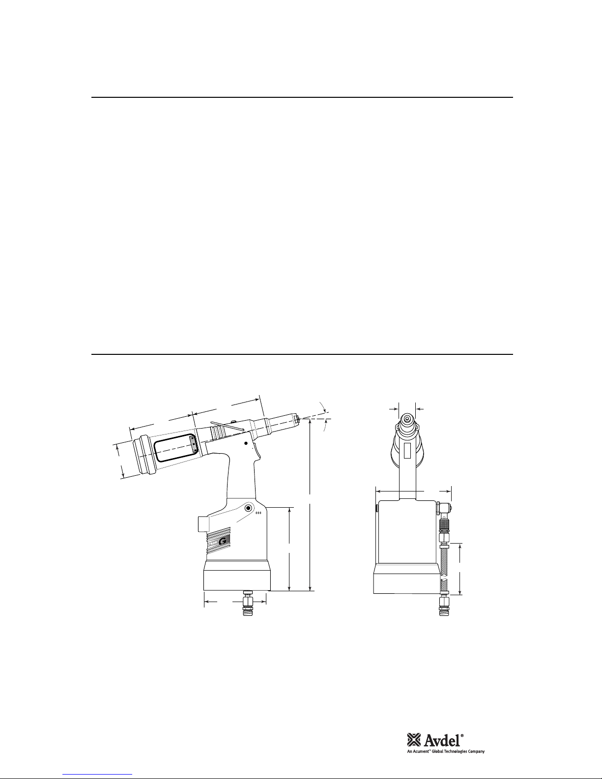
Dimensions in millimetres.
30
12°30'
134
128
152
150
316
145
116
70
4
Air Pressure Minimum - Maximum 5-7 bar (72.5 - 101.5 psi)
Free Air Volume Required @ 5.5 bar 4.3 litres (0.15 cuft)
Stroke Minimum 17 mm (0.7 in)
Pull Force @ 5.5 bar 18.68 kN (4200 lbf)
Cycle time Approximately 1.2 seconds
Noise Level 75 dB(A)
Weight Without nose equipment 2.35 kg (5.17 lb)
Vibration Less than 2.5 m/s2 (8.2 ft/s2)
Spe cifications
Too l S pe ci fi ca ti on s
Too l M ea su rem en ts
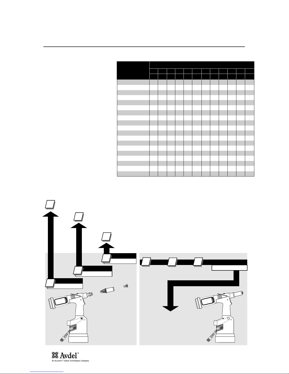
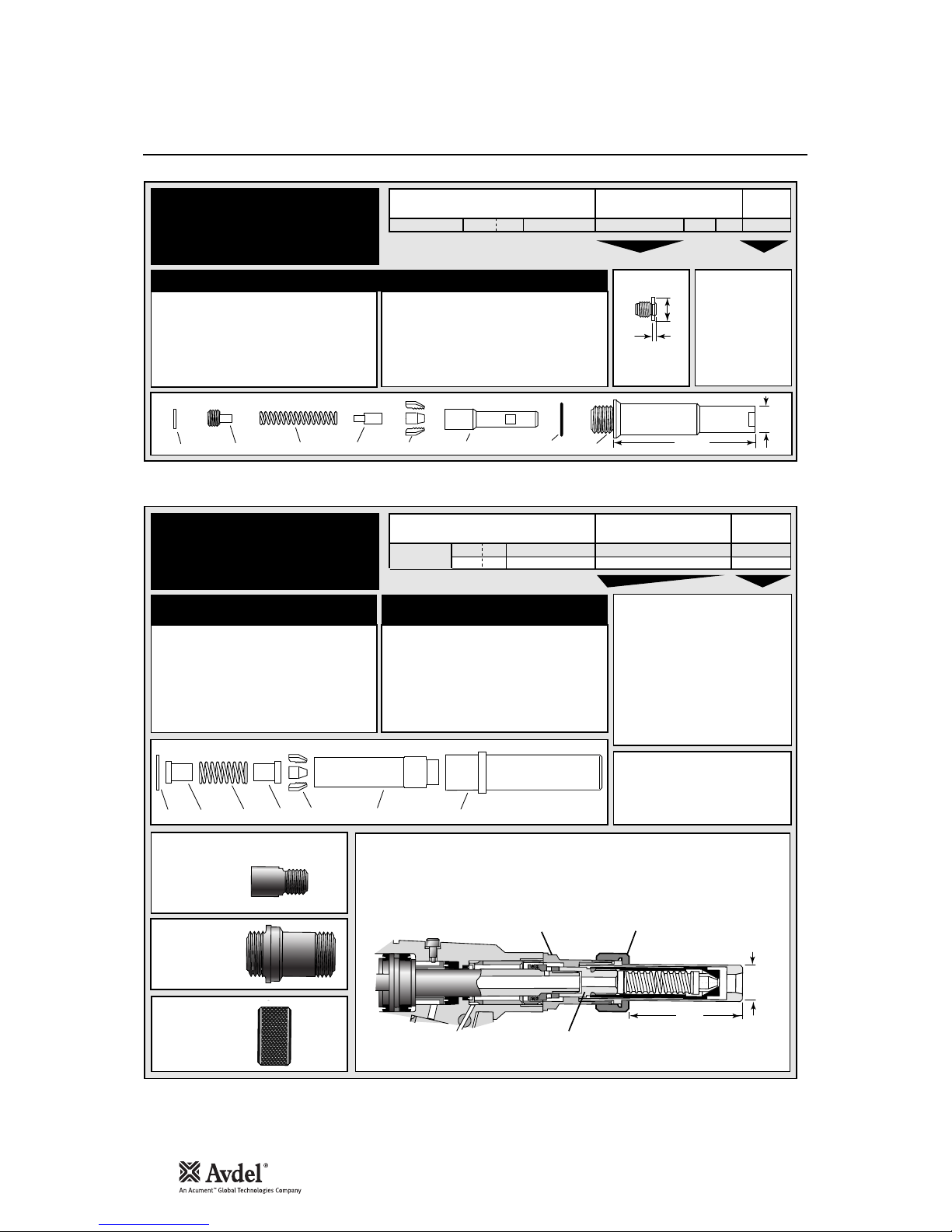
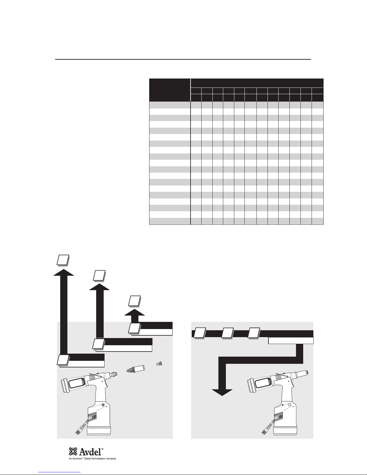
6
G4 HD is a hydro-pneumatic tool designed to
place Avdel®breakstem fasteners at high
speed making it ideal for batch or flow-line
assembly in a wide variety of applications
throughout all industries. It can place all
fasteners listed opposite.
The tool features an adjustable vacuum
system for fastener retention and trouble free
collection of the spent stems regardless of
tool orientation. See the ‘Operating Procedure’
on page 7 for adjustment instructions.
A complete tool is made up of three separate
elements which will be supplied individually.
See diagram below.
NOSE EQUIPMENT MUST BE FITTED AS
DESCRIBED ON PAGES 8-11.
FASTENER
NAME
MM
IN
FASTENER SIZE ( )
AVEX
®
STAVEX
®
AVINOX
®
AVIBULB
®
BULBEX
®
T-LOK
®
AVDEL® SR
INTERLOCK
®
HEMLOK
®
TLR
®
MAXLOK
®
AVTAINER
®
AVDEL
®
MBC
MBC/LC
AVSEAL
®
QTM RIVET
T
TM
RIVET
CHERRYMATE
TM
4.3 4.8 5 5.2 6 6.4 6.5 7 8 9 9.5 10
–
3
/16 – – –1/4 – – – –3/8 –
● ●
● ●
●
● ●
●
● ●
● ●
● ●
●
● ●
● ●
●
●
●
●
● ● ●
● ●
● ●
● ●
COMPLETE TOOL
71231-00 . . .
*
BASE TOOL
1
1
2
3
1
NOSE ASSEMBLY
NOSE TIP
2
71231-02000
71210-15000
see note 3
2
3
+ + =
3
4
4
The part number of the base tool remains the same whichever nose assembly, or nose tip is fitted. See the General Assembly
pages 18-19. If a Maxlok
®
nose assembly is fitted, the same base tool MUST be adapted. See details page 11.
The nose tip part number relates to a specific fastener. If access to the application is
restricted, some extended nose tips are available. See ‘type 2 nose tip’ table page 9.
This single nose assembly will allow placing of non-aerospace fasteners by simply selecting the appropriate nose
tip from the range of type 1 nose tips. Other nose assemblies are available for applications with restricted
access, for aerospace and special fasteners. See tables pages 8-10.
* ADD 3 DIGITS FROM THE
LAST COLUMN OF A NOSE TIP
TABLE ON PAGE 8, 9 OR 10.
FOR MAXLOK
®
, USE MAXLOK
®
TABLE PAGE 10 EVEN THOUGH
THERE IS NO NOSE TIP.
Int ent of Use
7
En g lish
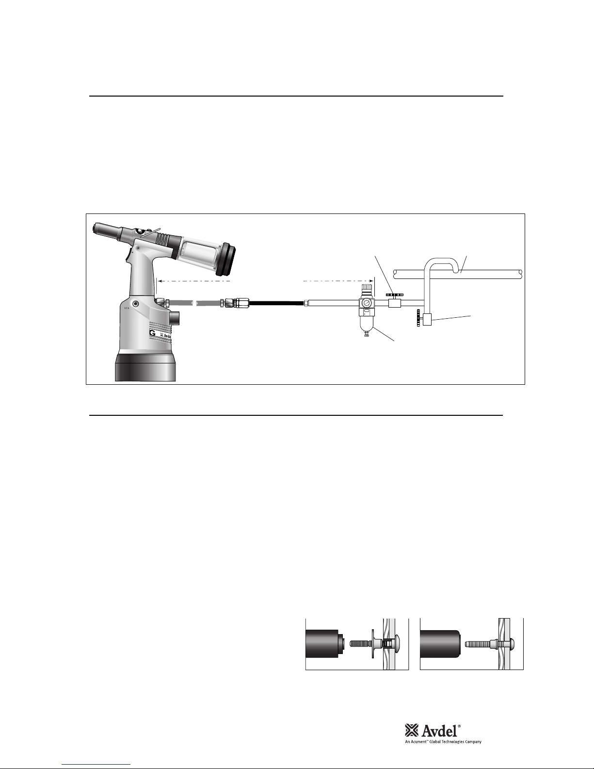
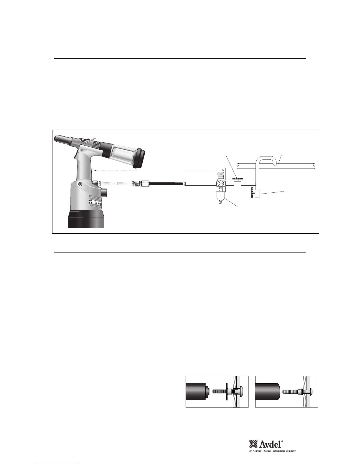
All tools are operated with compressed air at an optimum pressure of 5.5 bar. We recommend the use of pressure regulators and
automatic filtering systems on the main air supply. These should be fitted within 3 metres of the tool (see diagram below) to ensure
maximum tool life and minimum tool maintenance.
Air supply hoses should have a minimum working effective pressure rating of 150% of the maximum pressure produced in the system or
10 bar, whichever is the highest. Air hoses should be oil resistant, have an abrasion resistant exterior and should be armoured where
operating conditions may result in hoses being damaged. All air hoses MUST have a minimum bore diameter of 6.4 millimetres or 1/4
inch.
Read daily servicing details pages 13.
ADJUSTING THE VACUUM EXTRACTION
• Using a screwdriver, turn rotary valve 65 until the air flow at
the rear of the tool ceases.
• With the nose of the tool pointing downwards, insert a
fastener other than Avtainer®or Maxlok®, into the nose and
hold it into position.
• Turn the rotary valve either way until there is sufficient suction
to retain the fastener.
8
6
4
2
0
1
0
1
2
14
1
6
TAKE OFF POINT
FROM
MAIN SUPPLY
STOP COCK
(USED DURING MAINTENANCE
OF FILTER/REGULATOR OR LUBRICATION UNITS)
MAIN SUPPLY
DRAIN POINT
PRESSURE REGULATOR
AND FILTER (DRAIN DAILY)
3 METRES MAXIMUM
4
ALL FASTENERS EXCEPT AVTAINER®AND MAXLOK
®
• Ensure that a nose assembly suitable for the fastener is fitted
(see pages 8-10).
• Connect the tool to the air supply.
• Insert the fastener stem into the nose of the tool. The fastener
should remain held in by the vacuum system. If not, adjust the
vacuum extraction rotary valve 65 (see note below).
• Bring the tool with the fastener to the application so that the
protruding fastener enters squarely the hole of the application.
• Fully actuate the trigger. The tool cycle will broach the fastener
and the broken stem will be projected to the rear of the tool.
AVTAINER®AND MAXLOK
®
• Ensure that the correct nose assembly is fitted.
• Connect the tool to the air supply.
• Disable the vacuum extraction system by turning rotary
valve 65 until you feel or hear no air flow out of the front of
the nose assembly.
• Push the Maxlok
®
or Avtainer®stem through the application
hole.
• Place the collar on the stem (orientation as shown below).
• Keeping the head of the stem against the application, push
the tool onto the protruding stem.
• Fully depress the trigger. One cycle will ensure that the
collar is swaged into the lock grooves of the stem and that
the stem breaks at the breaker groove.
• Release the trigger. The tool completes its cycle by pushing
itself off the collar and the spent stem will be pushed to the
rear of the tool on insertion of the next fastener.
Item numbers in bold refer to the general assembly drawing and parts list on pages 18-19.
Placing AVTAINER
®
Placing MAXLOK
®
Put ting into Se rvice
Ai r Su pp ly
Op er at in g Pro ced ure

8
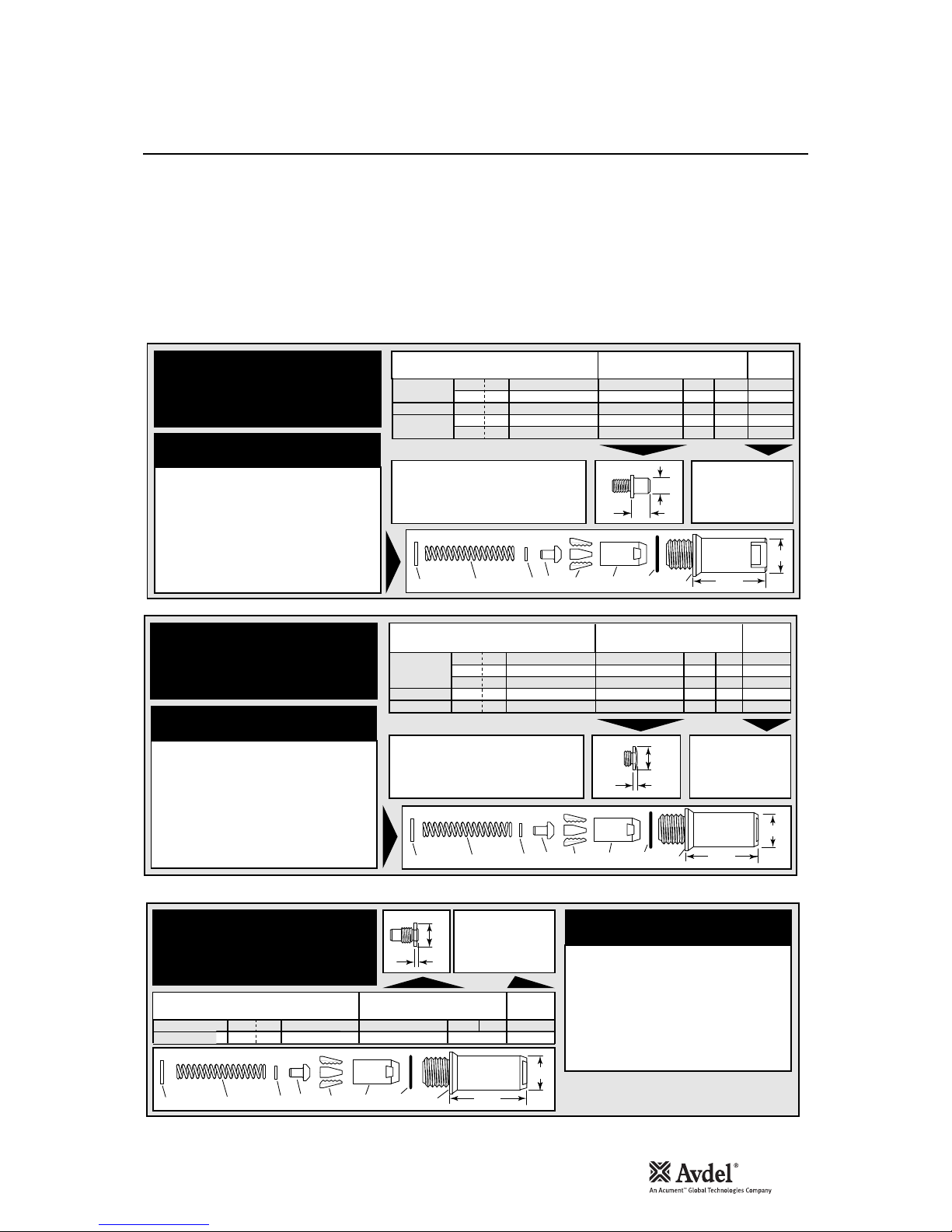
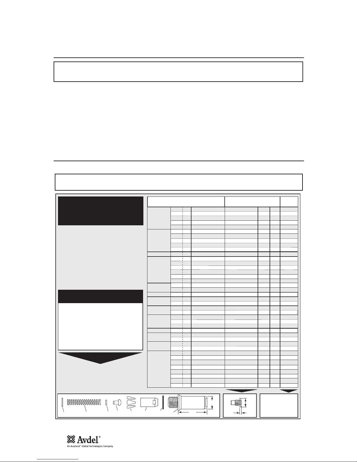
I M P O R T A N T
Nose assemblies do NOT include nose tips. Nose tips must be ordered separately.
A tool must always be fitted with the correct nose assembly and nose tip for your fastener and must be ordered separately, refer to
the ‘NOSE TIPS’ tables below and pages 9-10.
If your application presents no access restriction use a type 1 nose tip unless you are placing aerospace fasteners which require a
type 3 nose tip, Avtainer
®
a type 5, Hemlok®and 1/4” Interlock®a type 6. Maxlok®requires a special nose assembly which does not
make use of any nose tip, see pages 10-11.
Dimensions ‘A’ and ‘B’ will help you assess the suitability of a particular nose tip.
You should also check that the dimensions of the nose casing will not restrict access to your application. If access is restricted type 2
nose tips with extra reach, are available for some fasteners. Refer to the table on page 9.
It is essential that a fastener-compatible nose assembly and nose tip are fitted prior to operating the tool (no nose tip with Maxlok
®
).
I M P O R T A N T
The air supply must be disconnected when fitting or removing nose assemblies.
See page 9, except for Avtainer®and Maxlok®see page 11.
1
In inches then in millimetres.
2
Head forming nose tips for use with countersunk heads
ONLY.
3
Long nose tip for deep placing.
4
Material of the body then of the stem. 'Al' is the
abbreviation for Aluminium.
T Y P E 1
N O S E T I P S
F A ST EN E R
MATERIAL
Ø
1
N O SE T I P ( mm )
see
bel ow
PART Nº 'A' 'B'NAME
Alumini um
Alumini um
Steel
Alumini um
Alumini um
Steel
Steel
Stainle ss Steel
Steel
Steel
Alumini um
Alumini um
Alumini um
Alumini um
Alumini um
Alumini um
Alumini um
Alumini um
Alumini um
Stainle ss Steel
Steel
Steel
Steel
Steel
Any
Any
Any
Any
Any
Any
Any
Any
Al/Al
4
Al/Al
4
Al/Stee l
4
Al/Stee l
4
Al/Al
4
Al/Al
4
Al/Stee l
4
Al/Stee l
4
3
/
16
3
/
16
3
/
16
3
/
16
1
/
4
3
/
16
3
/
16
3
/
16
3
/
16
1
/
4
3
/
16
–
–
–
–
–
–
3
/
16
1
/
4
3
/
16
–
3
/
16
3
/
16
–
3
/
16
1
/
4
3
/
16
3
/
16
3
/
16
1
/
4
3
/
16
1
/
4
3/16
3/16
3/16
3/16
1/4
1/4
1/4
1/4
2.8
3.3
3.3
4.1
3.3
3.3
2.8
2.8
2.8
2.8
2.8
5.5
7.3
5.6
7.3
5.6
7.3
4.1
4.4
4.8
3.3
3.3
4.8
3.3
5.7
3.3
5.7
2.8
3.3
3.3
3.3
3.3
9.5
8.0
9.5
9.0
11. 2
8.0
10. 2
8.3
12. 7
19. 0
12. 7
12. 7
12. 7
19. 0
12. 7
12. 7
12. 7
12. 7
12. 7
12. 7
12. 7
12. 7
12. 7
12. 7
12. 7
12. 7
12. 7
12. 7
12. 7
12. 7
12. 7
12. 7
12. 7
12. 7
12. 7
12. 7
12. 7
12. 7
12. 7
12. 7
15. 9
12. 7
15. 9
12. 7
17. 5
12. 7
16. 7
12. 7
073 81- 0470 1
073 40- 0480 0
074 90- 0440 1
073 40- 0660 1
2
076 12- 0200 1
073 81- 0470 1
073 81- 0470 1
073 81- 0470 1
073 40- 0480 0
076 12- 0200 1
073 81- 0470 1
712 20- 1600 6
712 20- 1601 1
3
712 20- 1600 7
712 20- 1601 2
3
712 20- 1600 8
712 20- 1601 3
3
076 05- 0022 0
712 20- 1608 0
074 98- 0140 1
073 40- 0620 1
073 40- 0620 1
074 98- 0140 1
076 12- 0200 1
073 48- 0700 1
712 20- 6000 1
712 10- 1605 0
073 81- 0470 1
073 40- 0620 1
076 12- 0200 1
073 40- 0620 1
076 12- 0200 1
703 -A- 25-6 TA
703 -B- 21
703 -A- 25-6 T
703 -B- 26
743 -A- 25-8 TA
743 -B- 21
743 -A- 25-8 T
743 -B- 26
4.8
4.8
4.8
4.8
6.4
4.8
4.8
4.8
4.8
6.4
4.8
8
8
9
9
10
10
4.8
6.4
4.8
4.3
4.8
4.8
6
4.8
6.4
4.8
4.8
4.8
6.4
4.8
6.4
4.8
4.8
4.8
4.8
6.4
6.4
6.4
6.4
AVEX
®
Large flange
STAVEX
®
Countersunk
Large flange
BULBEX
®
AVSEAL
®
TLR
®
AVINOX
®
II
T-LOK
®
AVIBULB
®
AVDEL
®
SR
Countersunk
INTERLOCK
®
Q™ RIVET
CHERRYMATE
®
T™ RIVET
Large flange
Large flange
Large flange
Large flange
… 0 1 0
… 0 1 6
… 0 1 7
… 0 1 5
… 0 2 1
… 0 1 6
… 0 1 0
… 0 1 0
… 0 1 0
… 0 2 1
… 0 1 0
… 1 6 5
… 1 8 5
… 1 6 6
… 1 8 6
… 1 6 7
… 1 8 7
… 1 4 0
… 1 4 1
… 0 8 2
… 1 2 0
… 1 2 0
… 0 8 2
… 0 2 1
… 0 6 2
… 0 6 3
… 0 6 4
… 0 1 0
… 1 2 0
… 0 2 1
… 1 2 0
… 0 2 1
… 3 8 0
… 3 8 1
… 3 8 3
… 3 8 4
… 3 8 5
… 3 8 6
… 3 8 7
… 3 8 8
A
B
ITEM DESCRIPTION PART Nº
1 NOSE CASING 07340-00306
2 'O' RING 07003-00067
3 JAW HOUSING 07340-00304
4 JAWS 71210-15001
5 JAW SPREADER 07498-04502
6 BUFFER 71210-05001
7 SPRING 07500-00418
8 LOCKING RING 07340-00327
COMPLETE TOOL
PART NUMBER :
precede with
71231-00
8 7 6 5 4 23 1
61
22.9
N O S E AS S E M BL Y
part nº 71210-15000
Fi tt in g In st ru ct ion s
Nos e Assemblies
9
En g lish
Item numbers in bold refer to nose assembly components in type 1,2, 3 and 6 nose tip tables.
• Lightly coat jaws 4 with Moly lithium grease*.
• Drop jaws 4 into jaw housing 3.
• Insert jaw spreader 5 into jaw housing 3.
• Locate buffer 6 on jaw spreader 5.
• Locate spring 7 onto jaw spreader 5.
• Fit locking ring 8 onto the jaw spreader housing.
• Holding tool pointing down, screw the assembled jaw housing onto the jaw spreader housing and tighten with spanner*.
• Screw the nose tip into nose casing 1 and tighten with spanner*.
• Place nose casing 1 with ‘O’ ring 2 over jaw housing 3 and screw onto the tool, tightening with spanner*.
* Item included in the G4 service kit. For complete list see page 15.
1
In inches then in millimetres.
F A ST EN E R
MATERIAL
Ø
1
N O SE T I P ( mm )
see
bel ow
PART Nº 'A' 'B'NAME
Alumini um
Steel
Alumini um
Steel
Steel
3
/
16
3
/
16
3
/
16
–
3
/
16
10. 0
11. 8
10. 0
10. 0
10. 0
12. 7
12. 7
12. 7
12. 7
12. 7
073 40- 0280 7
073 40- 0730 1
073 40- 0280 7
072 41- 0710 1
072 41- 0710 1
4.8
4.8
4.8
4.3
4.8
AVEX
®
BULBEX
®
T-LOK
®
… 0 1 4
… 0 1 8
… 0 1 4
… 1 2 1
… 1 2 1
ITEM DESCRIPTION PART Nº
1 NOSE CASING 07340-02804
2 'O' RING 07003-00067
3 JAW HOUSING 07340-00304
4 JAWS 71210-15001
5 JAW SPREADER 07498-04502
6 BUFFER 71210-05001
7 SPRING 07500-00418
8 LOCKING RING 07340-00327
COMPLETE TOOL
PART NUMBER :
precede with
71231-00
N O S E AS S E M BL Y
part nº 71210-15200
A
B
TYPE 2 NOSE TIPS ARE EXTENDED
TO ALLOW ACCESS INTO
APPLICATIONS WHERE TYPE 1
NOSE TIPS WILL NOT REACH.
T Y P E 2
N O S E T I P S
8 7 6 5 4 23
1
58.3
22.9
T Y P E 3
N O S E T I P S
COMPLETE TOOL
PART NUMBER :
precede with
71231-00
1
56.3
22.9
1
In inches then in millimetres.
O
Oversize
N O S E AS S E M BL Y
part nº 71210-15300
ITEM DESCRIPTION PART Nº
1 NOSE CASING 07344-02001
2 'O' RING 07003-00067
3 JAW HOUSING 07340-00304
4 JAWS 71210-15001
5 JAW SPREADER 07498-04502
6 BUFFER 71210-05001
7 SPRING 07500-00418
8 LOCKING RING 07340-00327
F A ST EN E R
MATERIAL
Ø
1
N O SE T I P ( mm ) se e
bel ow
PART Nº 'A' 'B'NAME
Alumini um
Alumini um
O
Stainle ss Steel
Any
Any
3
/
16
3
/
16
3
/
16
3
/
16
3
/
16
2.5
2.5
2.4
5.1
4.6
12. 7
12. 7
12. 7
12. 7
12. 7
712 10- 1603 6
712 10- 1603 7
712 20- 1603 8
073 40- 0690 1
073 44- 0470 1
4.8
4.8
4.8
4.8
4.8
AV DEL
®
MB C
MB C L/C
… 2 9 3
… 2 9 4
… 2 9 5
… 3 1 0
… 3 2 0
A
B
8 7 6 5 4 23
TYPE 3 NOSE TIPS ARE SPECIFICALLY
FOR THE AEROSPACE FASTENERS
LISTED ABOVE.
1
In inches then in millimetres.
T Y P E 6
N O S E T I P S
F A ST EN E R
MATERIAL
Ø
1
N O SE T I P ( mm )
see
abo ve
PART Nº 'A' 'B'NAME
Any
Any
1
/
4
1
/
4
3.6
3.6
14. 3
14. 3
076 12- 0200 1
076 12- 0200 1
6.4
6.4
HEMLOK
®
INTERLOCK
®
… 2 6 1
… 2 6 1
A
B
ITEM DESCRIPTION PART Nº
1 NOSE CASING 07340-00306
2 'O' RING 07003-00067
3 JAW HOUSING 07612-02003
4 JAWS 07612-02002
5 JAW SPREADER 07498-04502
6 BUFFER 07498-03003
7 SPRING 07500-00418
8 LOCKING RING 07340-00327
COMPLETE TOOL
PART NUMBER :
precede with
71231-00
8 7 6 5 4 3 1
61
22.9
N O S E AS S E M BL Y
part nº 71230-15800
2
Nos e Assemblies
10
Nos e Assemblies
T Y P E 5
N O S E T I P
COMPLETE TOOL
PART NUMBER :
precede with
71231-00
1
1
In inches then in millimetres
N O S E AS S E M BL Y part nº 71230-15600
ITEM DESCRIPTION PART Nº
1 NOSE CASING 07498-00501
2 'O' RING 07003-00067
9 CHUCK COLLET 07498-00801
4 JAWS 07220-02302
ITEM DESCRIPTION PART Nº
10 FRONT SPRING GUIDE 07498-00803
7 SPRING 07500-02005
11 REAR SPRING GUIDE 07498-00503
8 LOCKING RING 07340-00327
F A ST EN E R
MATERIAL
Ø
1
N O SE T I P ( mm ) se e
bel ow
PART Nº 'A' 'B'NAME
Steel
3
/
8
4.119. 1074 98- 0080 2
9.6
… 2 4 3
98.5
20.6
11 7 10 4 298
A
B
AV TAINE R
®
M A X L O K®-
N O N O S E T I P
12
1
In inches then in millimetres
NOSE ASSEMBLY NOSE ASSEMBLY
part nº 07610-02000 for
3
/
16
" ø part nº 07610-02100 for 1/4 " ø
ITEM DESCRIPTION PART Nº
9
CHUCK COLLET 07610-02002
4 JAWS 07610-02003
10 SPRING GUIDE 07220-02104
7 SPRING 07610-02107
8 LOCKING RING 07610-02004
12 ANVIL
07610-02001
ITEM DESCRIPTION PART Nº
9
CHUCK COLLET 07610-02102
4 JAWS 07610-02103
10 SPRING GUIDE 07220-02104
7 SPRING 07610-02107
8 LOCKING RING 07610-02004
12 ANVIL
07610-02101
THE THREE COMPONENTS ILLUSTRATED LEFT ARE ESSENTIAL WHEN FITTING
A MAXLOK® NOSE ASSEMBLY TO THE G4 TOOL.
READ MAXLOK® 'FITTING INSTRUCTIONS' PAGE 11.
F A ST EN E R
MATERIAL
Ø
1
N O SE A S SE M BL Y see
bel ow
PART NºNAME
All
All
3
/
16
1
/
4
076 10- 0200 0
076 10- 0210 0
4.8
6.4
MA XLOK
®
… 3 7 1
… 3 7 2
8 7 10 9410
64.5
19
COMPLETE TOOL PART NUMBER :
precede with 71231-00
The three adapting components
illustrated below left are
not included in the nose
assembly part number.
Each item must be ordered
separately, using individual
part numbers.
MAXLOK
®
NOSE ASSEMBLIES
will place both the ordinary flange
collar and the large flange collars.
07610-00501
CHUCK COLLET ADAPTOR
CHUCK COLLET ADAPTOR
71230-02063
ANVIL ADAPTOR
ANVIL ADAPTOR
07610-00307
ANVIL NUT
ANVIL NUT

11
En g lish
I M P O R T A N T
The air supply must be disconnected when fitting or removing any nose assembly unless specifically instructed
otherwise.
The air vacuum extraction system MUST be disabled before operating a G4 tool with a Maxlok®or Avtainer®nose
assembly.
Refer to the ‘Operating Procedure’ for Avtainer®and Maxlok®, page 7.
AVTAINER
®
Item numbers in bold refer to the general assembly and parts
list pages 18-19. Other items numbers refer to the‘type 5 nose
tip’ table page 10.
• Remove jaw spreader housing 1, ‘O’ ring 2, and vacuum
tube 51.
• Replace jaw spreader housing 1, ‘O’ ring 2.
• Lightly coat jaws 4 with Moly Lithium grease*.
• Drop jaws 4 into chuck collet 9.
• Insert front spring guide 10 into chuck collet 9.
• Locate spring 7 onto front spring guide 10.
• Screw rear spring guide 11 into chuck collet 9.
• Fit locking ring 8 onto the jaw spreader housing of the tool.
• Screw the assembled chuck collet onto the jaw spreader
housing and tighten with spanner.
• Screw the nose tip into nose casing 1 and tighten with
spanner*.
• Place nose casing 1 with ‘O’ ring 2 over chuck collet 9 and
screw onto the tool, tightening with spanner*
MAXLOK
®
When fitting a Maxlok®nose assembly, the base tool must be
adapted using three auxiliary components illustrated page 10.
Item numbers in bold refer to the general assembly and parts
list pages 18-19. Other items numbers refer to the ‘Maxlok
®
no
nose tip’ table page 10.
• Remove jaw spreader housing 1, ‘O’ ring 2, and vacuum
tube 51.
• Substitute jaw spreader housing 1 with chuck collet adaptor
07610-00501. Tighten fully onto piston before tightening
the locknut against it.
• Fit locking ring 8 onto the chuck collet adaptor.
• Lightly coat jaws 4 with Moly lithium grease.
• Drop jaws 4 into or chuck collet 9.
• Insert one spring guide 10 into chuck collet 9.
• Locate spring 7 onto the spring guide already in place.
• Drop the other spring guide 10 into spring 7.
• Holding tool pointing down, screw the assembled chuck
collet onto the chuck collet adaptor and tighten with
spanner.
• Screw anvil adaptor 71230-02063 into the head assembly.
• Place anvil 12 over chuck collet 9 and lock into place with
anvil nut 07610-00307.
Nose assemblies should be serviced at weekly intervals. You should hold some stock of all internal components of the nose
assembly and nose tips as they will need regular replacement.
• Remove the nose assembly using the reverse procedure to the ‘Fitting instructions’.
• Any worn or damaged part should be replaced.
• Clean and check wear on jaws.
• Ensure that the jaw spreader is not distorted.
• Check that the spring is not distorted.
• On nose assemblies for Maxlok
®
and Avtainer®check that the spring guides are not distorted.
• On nose assemblies for Maxlok
®
check that the anvil is neither cracked nor has any scoring or corrosion marks on the inside face
of the concave shape at the front end.
• Assemble according to fitting instructions.
* Item included in the G4 service kit. For complete list see page 15.
Nos e Assemblies
Fi tt in g in st ru ct ion f or M ax lo k®an d Av ta in er®No se A ss em bl ie s
Se rv ic in g ins tr uc ti on s fo r al l N os e As se mb li es
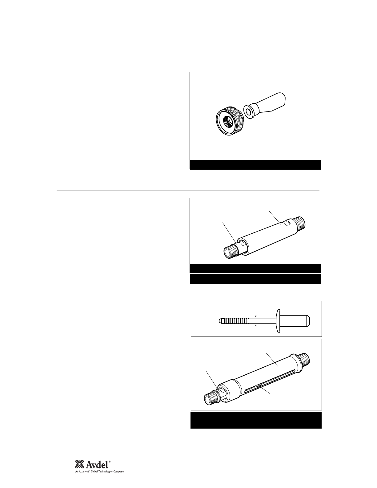
12
Acc essories
St em D ef le ct or
Ex te ns io n
Si de E je ct or
ADAPTOR NUT
71210-20101
STEM DEFLECTOR
07340-00342
The stem deflector is a very simple alternative to the standard
stem collector and allows access in restricted areas. It is easy
to fit to the tool as follows:
• Unscrew retaining nut 26 by inserting a 3 millimetre
diameter rod into one of the holes.
• Remove retaining nut 26 and the stem collector assembly,
items 18, 20, 21, 22, 23, 24, and 25.
• Screw the adaptor nut onto end cap 27.
• Push the boss end of the stem deflector into the internal
groove of the adaptor nut.
• Rotate the stem deflector until the aperture faces away
from the operator and other person(s) in the vicinity.
Item numbers in bold refer to the general assembly drawing and parts list on pages 18-19.
INNER
EXTENSION
OUTER CASING
KIT PART NUMBER: 71210-20100
STANDARD EXTENSION PART NUMBER: 71210-20300
INNER
EXTENSION
OUTER CASING
8-32 x 1/4" SOCKET
CAP HEAD SCREW
Part number: 07498-00900
for fasteners with a stem larger than 3.1 mm (1/8") Ø
STEM DIAMETER
Fitted between the tool and the nose assembly, the extension
gives an extra reach of 76 millimetres, ideal for use in deep
narrow applications.
• To fit the extension, remove any nose assembly
components.
• Screw the inner extension onto jaw spreader housing 1.
• Screw the outer casing onto head assembly 4.
• Screw the nose assembly onto the extension.
Fitted between the tool and the nose assembly, the side
ejector forces fastener stems to eject at the front of the tool
and gives an extra reach of 90mm. It is not an option when
placing Maxlok
®
fasteners.
• To fit the side ejector, remove any nose assembly
components.
• Remove the socket cap screw from the side ejector.
• Screw the inner extension onto jaw spreader housing 1.
• Screw the outer casing onto head assembly 4.
• Replace the socket cap screw securing with Loctite
Screwlock 222, part number 07900-00371.
• Screw the nose assembly onto the side ejector.
For greater ease of use, it is recommended that the stem
collector or stem deflector is replaced with safety cap part
number 71210-20201. ‘O’ ring 19 must remain.
3
/16" & 1/4" MAXLOK®EXTENSION: 71230-20300

13
En g lish
• Daily, before use or when first putting the tool into service, pour a few drops of clean, light lubricating oil into the air inlet of the
tool if no lubricator is fitted on air supply. If the tool is in continuous use, the air hose should be disconnected from the main air
supply and the tool lubricated every two to three hours.
• Check for air leaks. If damaged, hoses and couplings should be replaced.
• If there is no filter on the pressure regulator, bleed the air line to clear it of accumulated dirt or water before connecting the air
hose to the tool. If there is a filter, drain it.
• Check that the nose assembly is correct for the fastener to be placed.
• Check that the stroke of the tool meets the minimum specification (page 5). The last step of the Priming Procedure on page 19
explains how to measure the stroke.
• Either a stem collector or a stem deflector must be fitted to the tool if the vacuum extraction is ‘ON’. If it is turned ‘OFF’ a safety
cap must be fitted. See ‘side ejector’ opposite.
• Check that base cover 40 is fully tightened onto body 38.
• Ensure that rotary valve 65 is correctly adjusted for fastener retention or turned off for Avtainer
®
and Maxlok®(see ‘Operating
Procedure’ page 7).
• Dismantle and clean nose assembly, with special attention to the jaws. Lubricate with Moly Lithium grease EP 3753 before
assembling.
• Check for air leaks.
Grease can be ordered as a single item, the part number is shown in the service kit page 15.
First Aid
SKIN:
As the grease is completely water resistant it is best removed with an approved emulsifying skin cleaner.
INGESTION:
Ensure the individual drinks 30ml Milk of Magnesia, preferably in a cup of milk.
EYES:
Irritant but not harmful. Irrigate with water and seek medical attention.
Fire
FLASH POINT: Above 220°C.
Not classified as flammable.
Suitable extinguishing media: CO
2
, Halon or water spray if applied by an experienced operator.
Environment
Scrape up for burning or disposal on approved site.
Handling
Use barrier cream or oil resistant gloves
Storage
Away from heat and oxidising agent.
Item numbers in bold refer to the general assembly drawing and parts list on pages 18-19.
I M P O R T A N T
Read Safety Instructions on page 4.
The employer is responsible for ensuring that tool maintenance instructions are given to the appropriate personnel.
The operator should not be involved in maintenance or repair of the tool unless properly trained.
The tool shall be examined regularly for damage and malfunction.
Ser vicing the Tool
Da il y
Wee kl y
Mo ly L it hi um G re as e EP 3 75 3 Saf et y Da ta

14
Spe cifications
Mo ly Ko te 5 5m G re as e Sa fe ty D ata
Mo ly Ko te 1 11 G re as e Sa fe ty D ata
First Aid
SKIN:
Flush with water. Wipe off.
INGESTION:
No first aid should be needed.
EYES:
Flush with water.
Fire
FLASH POINT: Above 101.1°C. (closed cup)
Explosive Properties: No
Suitable Extinguishing Media: Carbon Dioxide Foam, Dry Powder or fine water spray.
Water can be used to cool fire exposed containers.
Environment
Do not allow large quantities to enter drains or surface waters.
Methods for cleaning up: Scrape up and place in suitable container fitted with a lid. The spilled product produces an extremely
slippery surface.
Harmful to aquatic organisms and may cause long-term adverse effects in the aquatic environment. However, due to the physical
form and water - insolubility of the product the bioavailability is negligible.
Handling
General ventilation is recommended. Avoid skin and eye contact.
Storage
Do not store with oxidizing agents. Keep container closed and store away from water or moisture.
First Aid
SKIN:
No first aid should be needed.
INGESTION:
No first aid should be needed.
EYES:
No first aid should be needed.
INHALATION:
No first aid should be needed.
Fire
FLASH POINT: Above 101.1°C. (closed cup)
Explosive Properties: No
Suitable Extinguishing Media: Carbon Dioxide Foam, Dry Powder or fine water spray.
Water can be used to cool fire exposed containers.
Environment
No adverse effects are predicted.
Handling
General ventilation is recommended. Avoid eye contact.
Storage
Do not store with oxidizing agents. Keep container closed and store away from water or moisture.

15
En g lish
The airline must be disconnected before any servicing or dismantling is attempted unless specifically instructed otherwise.
It is recommended that any dismantling operation be carried out in clean conditions.
Before proceeding with dismantling, empty the oil from the tool following the first three steps of the 'Priming Procedure' on page 21.
Prior to dismantling the tool it is necessary to remove the nose equipment. For instructions see the nose equipment section, pages 8-
11.
For a complete service of the tool, we advise that you proceed with dismantling of sub-assemblies in the order shown.
After any dismantling REMEMBER to prime the tool and to fit an appropriate nose assembly or swivel head.
I M P O R T A N T
Read Safety Instructions on page 4.
The employer is responsible for ensuring that tool maintenance instructions are given to the appropriate
personnel.
The operator should not be involved in maintenance or repair of the tool unless properly trained.
The tool should be examined regularly for damage and malfunction.
* Item included in the G4 service kit.
Item numbers in bold refer to the general assembly drawing and parts list on pages 18-19.
• Unscrew retaining nut 26 and pull off stem collector assembly, items 15, (72) 18, 20, 21, 22, 23, 24, 25 and ‘O’ ring 19.
• Using the ‘T’ spanner*, remove end cap 27 (73) together with seal 17 ‘O’ ring 16 and lip seal 28 and spring 70.
• Loosen locknut 3 with a spanner* then unscrew jaw spreader housing 1 and ‘O’ ring 2.
• Remove locknut 3 together with ‘O’ rings 49 and 50.
• Push head piston 7 to the rear and out of head assembly 4 taking care not to damage the cylinder bore.
• Remove seal retainer 30. Push lip seal 8 to the rear and out of head assembly 4 taking care again not to damage the cylinder
bore.
• Remove seal housing 5 and lip seal 67.
PART Nº DESCRIPTIONPART Nº DESCRIPTION
SERVICE KIT : 71210-99990 Spanners are specified in inches and across flats unless otherwise stated
07900-00667 PISTON SLEEVE
07900-00692 TRIGGER VALVE EXTRACTOR
07900-00670 BULLET
07900-00672 'T' SPANNER
07900-00706 'T' SPANNER SPIGOT
07900-00684 GUIDE TUBE
07900-00685 INSERTION ROD
07900-00351 3 MM ALLEN KEY
07900-00469 2.5 MM ALLEN KEY
07900-00158 2 MM PIN PUNCH
07900-00164 CIRCLIP PLIERS
07900-00008
7
/16 x 1/2 SPANNER
07900-00012
9
/16 x 5/8 SPANNER
07900-00015
5
/8 x 11/16 SPANNER
07900-00686 PEG SPANNER
07900-00677 SEAL EXTRACTOR
07900-00698 STOP NUT
07900-00700 PRIMING PUMP
07992-00020 GREASE - MOLY LITHIUM E.P.3753
07992-00075 GREASE - MOLYKOTE 55M
07900-00755 GREASE - MOLYKOTE 111
(or every 500,000 cycles whichever is the soonest)
Annually or every 500,000 cycles the tool should be completely dismantled and new components should be used where worn,
damaged or recommended. All ‘O’ rings and seals should be renewed and lubricated with MolyKote 55m grease for pneumatic sealing
or MolyKote 111 for hydraulic sealing.
For an easy complete service, Avdel is offering a complete service kit.
Ser vicing the Tool
An nu al ly
He ad A ss em bl y

16
Assemble in reverse order to dismantling noting the following points:
• Place lip seal 8 onto the insertion rod* ensuring correct orientation. Push the guide tube* into the head of the tool and push the
insertion rod* with the seal into place through the guide tube*. Pull the insertion rod* out then the guide tube.
• Drop seal retainer 30 against lip seal 8 large flange first.
• Fit seals 11 and 13 onto the piston.
• Lubricate the cylinder bore and place the piston sleeve* into the back of head assembly 4. Slide the bullet* onto the threaded part
of piston 7 and push the piston with the seals through the piston sleeve* as far as it will go. Slide the bullet* off the piston and
remove the piston sleeve.
• Fit seal housing 5 and lip seal 67.
• Tighten jaw spreader housing 1 fully tightened onto head piston 7 BEFORE tightening locknut 3 against it.
• Use Loctite 932 when reassembling Retaining Nut 26.
• Remove ‘ON/OFF’ valve assembly 60.
• Clamp the body of the inverted tool ACROSS THE AIR INLET BOSSES in a vice fitted with soft jaws.
• Pull off rubber boot 80.
• Using the peg spanner* unscrew base cover 40.
• Unscrew locknuts 76 (2 off) and remove base plate 77.
• Remove liner 45 together with sealing washers 75 (2 off) and 'O' rings 78 (2 off).
• Remove pneumatic piston assembly 42 together with ‘O’ ring 39, lip seal 41 (3 off) and guide ring 35.
Assemble in reverse order.
• Remove pneumatic piston assembly 42 and seal assembly 34 as described immediately above.
• Using the ‘T’ spanner* and ‘T’ spanner spigot* undo clamp nut 36 and remove it together with clamp plate 63, transfer tube
assembly 44, ‘O’ ring 6, valve rod 43 and silencer pads 62.
• Release the tool from the vice and separate body 38 with ‘O’ ring 31 from handle assembly 32.
• Remove ‘O’ ring 33 from the intensifier tube and pull off head assembly 4 from handle assembly 32.
• Push out valve seat 64 with both ‘O’ rings 6.
• Pull out all the components of valve spool assembly 54.
• Finally remove ‘O’ ring 59 out of the handle counterbore.
Assemble in reverse order noting the following points -
• Ensure that the central port in valve seat 64 faces upwards.
• Use Loctite 243 when reassembling Clamp Nut 36, torque to 11ft lb (14.91 Nm).
• Using the 2 millimetre diameter pin punch*, drive trigger pin 48 out and lift off trigger 47.
• Unscrew trigger valve 46 using the trigger valve extractor*.
Assemble in reverse order to dismantling.
I M P O R T A N T
Check the tool against daily and weekly servicing
Priming is ALWAYS necessary after the too has been dismantled and prior to operating.
* Item included in the G4 service kit. For complete list see page 15.
Item numbers in bold refer to the general assembly drawing and parts list on pages 18-19.
Ser vicing the Tool
He ad A ss em bl y
Pn eu ma ti c Pi st on As se mb ly
Valv e S po ol A ss em bl y
Tr ig ge r

17
En g lishNot es
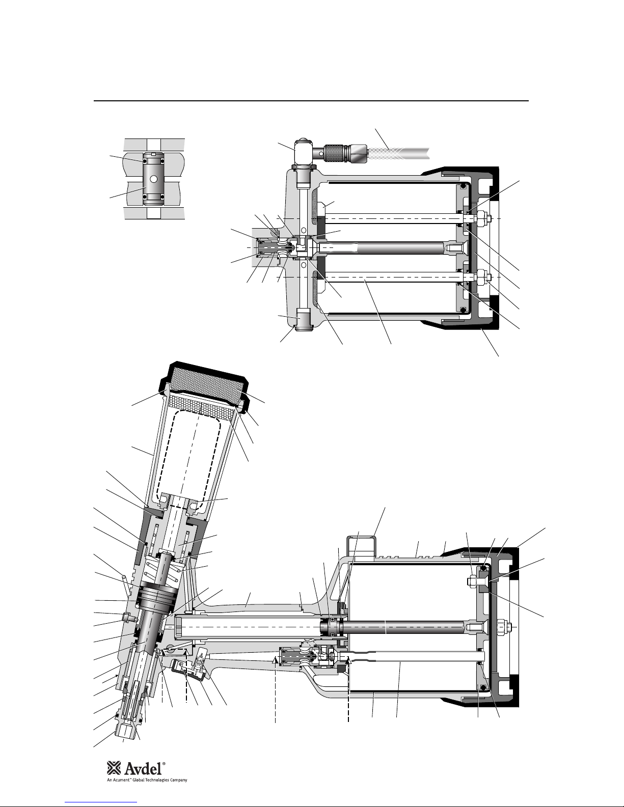
18
Gene ral Ass embly of Ba se Tool 712 31-0200 0
B - B
6665
37
848586
87
38
40
39
83
31
33
34
A
A
44
45
36
35
B
B
1 2 3 4 9 105 8
31
30
32
46
486747
51
50
49
26
73
70
28
72 16
17
18
14
20 21
22
25
24
11
7
A
23
13
88
42
41
80
8281
A - A
6
64
5958
57
54-56
55
52
53
6
61
60
69
6
74
80
41
76 7577
78
62
63

19
En g lish
010203040506070809101113141617182021222324252628303132333435363738394041424445
46
71210-02101
07003-00277
71230-02015
71230-03300
71210-02104
07003-00281
71231-02003
07003-00273
71230-02041
07003-00194
07003-00341
07003-00342
71210-02022
07003-00278
71210-02029
07003-00311
07640-00239
71210-02051
07640-00244
71210-02034
07340-00335
71210-02035
71210-02028
07003-00374
71230-02019
07003-00288
71221-02013
07003-00287
71230-03800
71230-03205
71210-02014
71231-02027
71221-02001
07003-00182
71221-02002
07003-00274
71231-03210
71230-03600
71221-02008
07005-00088
JAW SPREADER HOUSING
'O' RING
LOCKNUT
HEAD ASSEMBLY
SEAL HOUSING
'O' RING
HEAD PISTON
LIP SEAL
SCREW
BONDED SEAL
LIP SEAL
'O' RING
SUSPENSION RING
'O' RING
SEAL
'O' RING
STEM COLLECTOR OUTER
STEM COLLECTOR BODY
SILENCER
SILENCER CAP
STEM COLLECTOR END CAP
SILENCER
RETAINING NUT
LIP SEAL
SEAL RETAINER
'O' RING
HANDLE ASSEMBLY
'O' RING
INTENSIFIER SEAL ASSEMBLY
GUIDE RING
CLAMP NUT
LABEL
BODY
'O' RING
BASE COVER
LIP SEAL
PNEUMATIC PISTON ASSEMBLY (INCLUDES 41/35/39)
TRANSFER TUBE ASSEMBLY
CYLINDER LINER
TRIGGER VALVE
111113111112111111111111112111111113111
1
-
1
1
-
-3-
112121111
-
-1-
-1---
-
211
-
-1-1-1---
-
4748495051525354555657585960616263646566676869707273747576777879808182838485868788
71210-02008
71210-02024
07003-00310
07003-00204
71230-02102
07003-00127
07005-01274
71210-03400
07003-00268
71210-03402
71210-03401
07003-00042
07003-00271
71210-03700
07008-00010
71210-02031
71221-02003
71210-02009
71210-02013
07003-00189
07003-00333
07900-00707
07007-00224
07490-03002
71403-02110
71231-02001
71221-02004
71221-02006
07002-00108
71221-02005
07003-00027
71221-02003
71221-02007
07007-01993
71221-20104
07002-00098
71221-20105
71221-20101
71221-20102
71221-20103
07007-01503
TRIGGER
TRIGGER PIN
'O' RING
'O' RING
VACUUM SLEEVE
'O' RING
1/8" BSP PLUG
VALVE SPOOL ASSEMBLY (55 to 58)
• 'O' RING
• VALVE SPOOL
• VALVE BODY
• 'O' RING
'O' RING
ON/OFF VALVE ASSEMBLY
6" FLEXIBLE HOSE
SILENCER
TOP PLATE
VALVE SEAT
ROTARY VALVE
'O' RING
LIP SEAL
TOOL INSTRUCTION MANUAL
SPIROL PINS
SPRING
BOTTLE ADAPTOR ASSEMBLY
END CAP ASSEMBLY
TIE ROD
SEALING WASHER
M6 NYLOK NUT
BASE PLATE
'O' RING
TOP PLATE
RUBBER BOOT
CENTRE POLE MAGNET
M5 X 19 COUNTERSUNK SCREW
M5 NYLOK NUT
COUNTER
COUNTER MOULDING
SPECIAL M4 SCREW
MOULD RETAINING NUT
LABEL BOOK SYMBOL
11211111111111121112112111222121111111221
-
-
2
1-1
-
-2-
-
2
1
-
-2-
1–2-1
-------------------
ITEM PART Nº DESCRIPTION ITEM PART Nº DESCRIPTION
71231 - 0 2 000 PARTS LI S T * Th ese are mini mum reco mme n ded lev e ls o f s pare s ba sed on r egul ar s ervi cing
QTY SPARES QTY SPARES
Par ts List for 71 231-020 00

20
Pri ming
Oi l De ta il s
Hy sp in V G 32 O il Sa fe ty D at a
Pr im in g Ki t
To enable you to follow the priming procedure opposite, you will need to obtain a priming kit:
PART Nº DESCRIPTION
PRIMING KIT : 07900-00688
07900-00351 3mm ALLEN KEY
07900-00698 STOP NUT
07900-00700 PRIMING PUMP
07900-00224 4mm ALLEN KEY
07900-00734 MAXLOK
®
STOP NUT
Priming is ALWAYS necessary after the tool has been dismantled and prior to operating. It may also be necessary to restore the full
stroke after considerable use, when the stroke may be reduced and fasteners are not fully placed by one operation of the trigger.
The recommended oil for priming is Hyspin VG32 available in 0.5l (part number 07992-00002) or one gallon containers (part number
07992-00006). Please see safety data below.
First Aid
SKIN:
Wash thoroughly with soap and water as soon as possible. Casual contact requires no immediate attention. Short term contact requires no
immediate attention.
INGESTION:
Seek medical attention immediately. DO NOT induce vomiting.
EYES:
Irrigate immediately with water for several minutes. Although NOT a primary irritant, minor irritation may occur following contact.
Fire
Flash point 232°C. Not classified as flammable.
Suitable extinguishing media: CO
2
, dry powder, foam or water fog. DO NOT use water jets.
Environment
WASTE DISPOSAL: Through authorised contractor to a licensed site. May be incinerated. Used product may be sent for reclamation.
SPILLAGE: Prevent entry into drains, sewers and water courses. Soak up with absorbent material.
Handling
Wear eye protection, impervious gloves (e.g. of PVC) and a plastic apron. Use in well ventilated area.
Storage
No special precautions.

21
En g lish
I M P O R T A N T
DISCONNECT THE TOOL FROM THE AIR SUPPLY OR SWITCH OFF AT VALVE 55.
REMOVE NOSE ASSEMBLY OR SWIVEL HEAD COMPONENTS.
All operations should be carried out on a clean bench, with clean hands in a clean area.
Ensure that the new oil is perfectly clean and free from air bubbles.
Care MUST be taken at all times, to ensure that no foreign matter enters the tool, or serious damage may result.
• Remove bleed screw 9 and seal 10.
• Connect air supply to tool and switch ON/OFF valve 60 to "ON” position.
• Invert tool over suitable container and actuate trigger. Waste oil will be ejected through the bleed screw hole.
CARE SHALL BE TAKEN TO ENSURE THAT THE BLEED HOLE IS NOT DIRECTED TOWARDS THE OPERATOR OR OTHER
PERSONNEL.
• Screw stop nut 07900-00698 onto jaw spreader housing 1.
• Disconnect air supply to tool or switch ON/OFF valve 60 to ‘OFF” position.
• Fill the priming pump with oil.
• Screw priming pump 07900-00700 into the bleed screw hole with seal 10 in place.
• Actuate the priming pump by pressing down and releasing several times until resistance is felt.
• Remove the priming pump and the stop nut.
• Replace bleed screw 9 and seal 10.
• Connect air supply to tool and switch ON/OFF valve 60 to ‘ON” position.
• Check that the stroke of the tool meets the minimum specification of 17 millimetres. To check the stroke, measure the distance
between the front face of jaw spreader housing 1 and the front face of the head, BEFORE pressing the trigger and when the
trigger is fully actuated. The stroke is the difference between the two measurements. If it does not meet the minimum
specification, repeat the priming procedure.
Item numbers in bold refer to the general assembly drawing and parts list on pages 18-19.
Pri ming
Pr im in g Pro ce dure

22
Fau lt Diagnosis
Sym pt o m P o ss ibl e C au s e Re me d y Pag e R ef
Item numbers in bold refer to the general assembly drawing and parts list on pages 18-19.
More than one Air leak Tighten joints or replace components
operation of the Insufficient air pressure Adjust air pressure to within specification 5
trigger needed to Lack of lubrication Lubricate tool at air inlet point 7 & 13
place fastener Worn or broken jaws Fit new jaws 8-11
Low oil level or air in oil Prime tool 20-21
Build up of dirt inside the nose assembly Service 11
Tool will not grip Worn or broken jaws Fit new jaws 8-11
stem of fastener Build up of dirt inside the nose assembly Service 11
Loose jaw housing or chuck collet Tighten against locking ring 9-11
Weak or broken spring in nose assembly Fit new spring 8-11
Incorrect component in nose assembly Identify and replace 8-11
Rotary valve incorrectly adjusted Read ‘Operating Procedure’ 7
Jaws will not release Build up of dirt inside the nose assembly Service 11
broken stem of Jaw housing or chuck collet, nose tip and
fastener nose casing not properly seated Tighten nose assembly 9-11
Weak or broken spring in nose assembly Fit new spring 8-11
Air or oil leak Tighten joints or replace components
Low oil level or air present in oil Prime tool 20-21
Cannot feed next Broken stems jammed inside tool Empty stem collector 4 (point 14)
fastener Check jaw spreader is correct 8-11
Adjust air pressure to within specification 5
Rotary valve incorrectly adjusted Adjust following ‘Operating Procedure’ 7
Slow cycle Lack of lubrication Lubricate tool at air inlet point 7 & 13
Low air pressure Adjust air pressure to within the specification 5
Build up of dirt inside the nose assembly Service 11
Tool fails to operate No air pressure Connect and adjust to within the specification 5
Damaged trigger valve 42 Replace 16
Loose base cover 35 Tighten 16
Loose stem collector Tighten retaining nut 22 16
Fastener fails to break Insufficient air pressure Adjust air pressure to within specification 5
Fastener outside tool capability Use more powerful Genesis tool.
Contact Avdel
Low oil level or air present in oil Prime tool 20-21
Incorrect length of fastener (Maxlok®ONLY) Change to correct length
Tool fails to swage Insufficient air pressure Adjust air pressure to within specification 5
collar (Maxlok®ONLY) Worn or damaged anvil Replace 10-11
Low oil level or air present in oil Prime tool 20-21
Incorrect length of fastener Change to correct length
Other symptoms or failures should be reported to your local Avdel authorised distributor or repair centre.

Declaration of Conformity
We, Avdel UK Limited, Mundells, Welwyn Garden City, Herts, AL7 1EZ
declare under our sole responsibility that the product:
Model G4 HD
Serial No. ................................................
to which this declaration relates is in conformity with the following standards:
EN292 part 1 and part 2
ISO 8662 part 1 EN 60742/0695
ISO 3744 EN 50081-1
ISO PREN792 part 14 EN 55014
following the provisions of the Machine Directive 89/392/EC
(as amended by Directive 91/368/EC, 93/44/EC) and 93/68/EC
23
Welwyn Garden City - date of issue
A R Dear - Design & Development Manager
This box contains a power tool which is in
conformity with Machines Directive 89/392/EC.
The ‘Declaration of Conformity’ is contained
within.


25
Da n sk
Sikkerhedsregler 26
Specifikationer
Værktøjsspecifikationer 27
Værktøjsdimensioner 27
Anvendelsesformål
Nitter 28
Delnummerering 28
Værktøjets idriftsættelse
Lufttilførsel 29
Driftsvejledning 29
Justering af vakuumsuget 29
Næsekonstruktioner
Næsetipper 30-32
Monteringsvejledning 31
Monteringsvejledning for Maxlok
®
og Avtainer
®
33
Servicevejledning for alle næsekonstruktioner 33
Tilbehør
Dorndeflektor 34
Forlænger 34
Sideudstøder 34
Service af værktøjet
Dagligt / ugentligt 35
Moly Lithium smørefedt EP 3753 Sikkerhedsdata 35
Sikkerhedsdata til MolyKote 55m & MolyKote 111 36
Årligt 37
Serviceudstyr 37
Hovedkonstruktion 37-38
Trykluftsstempelkonstruktion 38
Ventilspolekonstruktion 38
Udløser 38
Generel konstruktion af grundværktøjet
Generel konstruktion og reservedelsliste 40-41
Smøring
Oplysninger om olie 42
Hyspin olie VG 32 sikkerhedsdata 42
Smøreudstyr 42
Smøreprocedure 43
Fejlsøgning
Symptom, mulig årsag og afhjælpningsmetode 44-45
Avdel UK Limited har en politik om konstant produktudvikling og forbedring, og der tages forbehold for ændringer af et produkt uden videre varsel.
Garanti
Avdel installationsværktøjer leveres med 12 måneders garanti mod defekter, som
skyldes mangelfulde materialer eller dårlig udførelse af produktet, og garantiperioden
starter fra leveringsdatoen, som bekræftes på fakturaen eller følgesedlen.
Garantien gælder for brugeren/køberen, når værktøjet sælges af en autoriseret
forhandler, og kun såfremt det bruges til det påtænkte formål. Garantien bortfalder,
hvis installationsværktøjet ikke efterses, vedligeholdes eller benyttes i
overensstemmelse med de instrukser, som findes i instruktions- og
servicehåndbøgerne
Kun i tilfælde af defekter eller fejl og efter eget skøn påtager Avdel d sig at reparere
eller udskifte de mangelfulde komponenter.
Ind holdsforteg nelse

26
Sik kerhedsregler
1 Bør ikke anvendes til andet end det påtænkte formål.
2 Værktøjet må ikke anvendes med andet udstyr end det, der anbefales og leveres af Avdel UK Limited.
3 Eventuelle ændringer af værktøjet/maskinen, næsekonstruktioner, tilbehør eller andet udstyr leveret af Avdel UK Limited eller
repræsentanter herfor, sker på kundens fulde ansvar. Avdel UK Limited rådgiver gerne ved eventuelle ændringer.
4 Værktøjet/maskinen bør til enhver tid vedligeholdes under sikre arbejdsforhold og gennemgås med regelmæssige intervaller for
skader og funktionalitet af faglært, kompetent personale. Eventuel afmontering må kun foretages af personale, trænet i Avdel UK
Limited’ procedurer. Værktøjet/maskinen bør ikke adskilles, uden man først henviser til vedligeholdelsesvejledningerne. Kontakt
venligst Avdel UK Limited med henblik på Deres uddannelsesbehov.
5 Værktøjet/maskinen bør til enhver tid betjenes i overensstemmelse med den relevante sundheds- og sikkerhedslovgivning.
Gældende love i UK er ”The Health and Safety at Work etc. Act 1974”. Spørgsmål vedrørende korrekt betjening af
værktøjet/maskinen samt brugersikkerhed bør rettes til Avdel UK Limited.
6 Kunden har pligt til at forklare for alle brugere de sikkerhedsforanstaltninger, der gør sig gældende ved brug af værktøjet/maskinen.
7 Luftledningen bør altid kobles fra værktøjets indsugning, inden man gør forsøg på at justere, montere eller fjerne
næsekonstruktionen.
8 Værktøjet må ikke betjenes, når det er rettet mod andre person(er) eller operatøren selv.
9 Sørg altid for at have et godt fodfæste eller en stabil position, inden værktøjet betjenes.
10 Kontrollér, at ventilationsåbningerne ikke er blokeret eller dækket til.
11 Driftstrykket bør ikke overstige 7 bar.
12 Værktøjet må ikke betjenes, hvis det ikke er udstyret med en komplet næsekonstruktion, med mindre der gives instrukser om
andet.
13 Sørg omhyggeligt for, at brugte dorne ikke udgør en risiko.
14 Hvis værktøjet er udstyret med en dornopsamler, skal den tømmes, når den er halvt fuld.
15 Hvis G4-værktøjet er udstyret med en dorndeflektor, skal den drejes indtil åbningen vender væk fra operatøren og andre personer,
som arbejder i nærheden.
16 Når værktøjet anvendes, er det påkrævet for operatøren og andre personer i nærheden at bære sikkerhedsbriller for at beskytte
mod nitteudstødning, hvis en nitte skydes ud ‘i luften’. Det anbefales at bruge handsker, hvis der er skarpe kanter eller hjørner på
applikationen.
17 Undgå indvikling af løsthængende tøj, slips, langt hår, rengøringsklude osv. i de bevægelige dele i værktøjet, som bør holdes tørre
og rene for at opnå det bedst mulige greb.
18 Når værktøjet transporteres, skal De holde hænderne væk fra udløseren/betjeningshåndtaget for at undgå uagtsom start af
værktøjet.
19 Overdreven kontakt med hydraulikolie bør undgås. For at mindske risikoen for udslæt skal man sørge for at vaske sig grundigt
ved evt. kontakt.
Denne instruktionshåndbog og følgende sikkerhedsregler skal læses af enhver person, som installerer,
benytter eller yder service på dette værktøj.

27
Da n sk
Dimensioner i millimeter
30
12°30'
134
128
152
150
316
145
116
70
4
Lufttryk Minimum - Maksimum 5-7 bar (72,5 - 101,5 psi)
Frit luftvolumenbehov v. 5,5 bar 4,3 litres (0,15 kubikfod)
Slaglængde Minimum 17 mm (0,7 tommer)
Trækkraft v. 5,5 bar 18,68 kN (4200 lbf)
Omløbstid Cirka 1,2 sekunder
Støjniveau 75 dB(A)
Vægt Uden næseudstyr 2,35 kg (5,17 lb)
Vibration Mindre end 2,5 m/s2(8,2 fod/s2)
Spe cifikationer
Væ rk tø js sp ec if ik ati on er
Væ rk tø js di me ns io ner
28
G4 er et hydropneumatisk værktøj, der er
konstrueret til at anbringe Avdel®-nitter med
afbrækkelig dorn ved høj hastighed. Dette
gør det ideelt til montering i forbindelse med
serie- og kontinuerlig produktion i en lang
række områder inden for alle industrier. Det
kan anbringe alle de typer nitter, der er vist
på modsatte side.
Værktøjet har et justerbart vakuumsystem til
fastholdelse af nitter og problemfri opsamling
af brugte dorne uanset værktøjets
orientering. Se 'Driftsvejledning' på side 29
for en vejledning af justering.
Et komplet værktøj består af tre separate
elementer, som leveres enkeltvis. Se
diagrammet nedenfor.
NÆSEUDSTYR SKAL MONTERES SOM
BESKREVET PÅ SIDE 30-33.
AVEX
®
STAVEX
®
AVINOX
®
AVIBULB
®
BULBEX
®
T-LOK
®
AVDEL® SR
INTERLOCK
®
HEMLOK
®
TLR
®
MAXLOK
®
AVTAINER
®
AVDEL
®
MBC
MBC/LC
AVSEAL
®
QTM RIVET
TTM RIVET
CHERRYMATE
TM
4.3 4.8 5 5.2 6 6.4 6.5 7 8 9 9.5 10
–
3
/16 – – – 1/4 – – – – 3/8 –
● ●
● ●
●
● ●
●
● ●
● ●
● ●
●
● ●
● ●
●
●
●
●
● ● ●
● ●
● ●
● ●
MM
IN
NAVN PÅ
NITTE
STØRRELSE PÅ NITTE ( )
KOMPLET VÆRKTØJ
71231-00 . . .
*
BASISVÆRKTØJ
1
1
2
3
1
NÆSEKONSTRUKTION
NÆSETIP
2
71231-02000
71210-15000
se bemærkning 3
2
3
+ + =
3
*
TILFØJ 3 CIFRE FRA DEN
SIDSTE KOLONNE I
NÆSETIPTABELLEN PÅ SIDE 30,
31 ELLER 32.
I FORB. MED MAXLOK
®
ANVENDES MAXLOK
®
-TABELLEN
PÅ SIDE 32, SELVOM DER IKKE
ER NOGEN NÆSETIP.
4
4
Delnummeret på grundværktøjet forbliver det samme, uanset hvilken næsekonstruktion eller næsetip, der er sat på. Se den generelle
konstruktion på side 40-41. Hvis værktøjet er udstyret med en Maxlok
®
-næsekonstruktion, SKAL det samme grundværktøj tilpasses.
Se detaljerne på side 33.
Næsetippens delnummer relaterer til en bestemt nitte. Hvis adgang til emnet er begrænset, findes
der enkelte forlængede næsetipper. Se tabellen for ‘Næsetipper af type 2’ på side 31.
Denne næsekonstruktion vil gøre det muligt at sætte standard nitter (ikke fly-industri) ved ganske enkelt at vælge den
korrekte næsetip fra udvalget af næsetipper af type 1. Der findes andre næsekonstruktioner til emner med begrænset
adgang, til fly-industri og særlige nitter. Se tabellerne på side 30-32.
Anv endelsesform ål
29
Da n sk
Alle værktøjer drives med trykluft ved et optimalt tryk på 5,5 bar. Vi anbefaler brug af trykregulatorer og automatisk
oliering/filtrering på hovedlufttilførslen. Disse monteres indenfor 3 meters afstand fra værktøjet (se nedenstående
diagram) for at sikre maksimal levetid og minimal vedligeholdelse af værktøjet.
Lufttilførselsslangernes minimumskapacitet bør være et effektivt arbejdstryk på 150% af det maksimale tryk, der
produceres i systemet, eller 10 bar, alt efter hvilket af disse udgør det højeste tryk. Luftslanger bør være oliebestandige
med slidbestandig yderside og armering, såfremt slangen udsættes for skadevoldende drift. Alle luftslanger SKAL have en
minimumshuldiameter på 6,4 mm eller
1/
4
".
Vedrørende daglig vedligeholdelse, se side 35.
JUSTERING AF VAKUUMSUGET
• Drej ventilen 65 ved brug af en skruetrækker, indtil
luftstrømmen ved værktøjets bagende stopper.
• Indfør en nitte, som ikke er en Avtainer
®
eller Maxlok®, i
næsen med værktøjsnæsen pegende nedad, og hold den på
plads.
• Drej ventilen den ene eller den anden vej, indtil der er
tilstrækkeligt sug til at fastolde nitten.
8
6
4
2
0
10
12
14
16
STARTPUNKT FRA
HOVEDTILFØRSLEN
STOPHANE
(ANVENDES UNDER SERVICE
AF FILTER/REGULATOR ELLER SMØREKOP)
UDTØMNINGSPUNKT
FOR HOVEDTILFØRSLEN
TRYKREGULATOR OG FILTER
(TØMMES DAGLIGT)
MAKSIMALT 3 METER
4
ALLE NITTER BORTSET FRA AVTAINER®OG MAXLOK
®
• Sørg for at en næsekonstruktion, der passer til nitten, er sat på
(se side 30-32).
• Tilslut værktøjet til lufttilførslen.
• Indfør nittedornen i næsen på værktøjet. Nitten bør fastholdes af
vakuumsystemet. Hvis ikke, justeres vakuum ventilen 65 (se
bemærkningen nedenfor).
• Før værktøjet med nitten hen til emnet, således at den
fremspringende nitte trænger lige ind i hullet på emnet.
• Aktivér udløseren helt. Værktøjscyklussen vil antrække nitten, og
den afbrækkede dorn vil blive skudt tilbage i værktøjets bagende.
AVTAINER®OG MAXLOK
®
• Sørg for at den rigtige næsekonstruktion er sat på.
• Tilslut værktøjet til lufttilførslen.
• Kobl vakuumsystemet fra ved at dreje ventilen 65, indtil De
ikke kan høre eller føle luft strømme ud forrest fra
næsekonstruktionen.
• Skub Maxlok
®
- eller Avtainer®-skaftet gennem hullet i emnet.
• Anbring kraven på skaftet (orienteringen vises nedenfor).
• Skub værktøjet hen på det fremspringende skaft, mens De
holder bottens hoved mod emnet.
• Tryk udløseren helt i bund. En cyklus vil sikre, at kraven
sænkes ned i låserillerne, og at skaftet brækkes af i
afbrækningsrillen.
• Giv slip på udløseren. Værktøjet fuldfører dets cyklus ved at
skubbe sig selv af kraven, og det afknækkede skaft vil blive
skubbet til værktøjets bagende ved indføring af den næste
bolt.
Delene med fed skrift refererer til den generelle konstruktion og reservedelslisten på side 40-41.
Anbringelse af AVTAINER
®
Anbringelse af MAXLOK
®
Vær ktøjets idri ftsættelse
Lu ft ti lf ør se l
Dr if ts ve jl ed ni ng
30
V I G T I G T
Næsekonstruktioner omfatter IKKE næsetipper. Næsetipper skal bestilles separat.
Et værktøj skal altid være udstyret med en korrekt næsekonstruktion og næsetip til Deres nitte og skal bestilles separat. Se
‘NÆSETIP’ tabellerne nedenfor og på side 31-32.
Hvis der ikke er nogen adgangsbegrænsning i Deres applikation, skal De bruge en næsetip af type 1, med mindre De anbringer flynitter, som kræver en næsetip af type 3, en Avtainer
®
af type 5, en Hemlok®og en 1/4" Interlock®af type 6. Maxlok®kræver en
særlig næsekonstruktion, som ikke gør brug af en næsetip. Se side 32-33.
Dimensionerne ‘A’ og ‘B’ vil hjælpe Dem med at vurdere, hvor passende en bestemt næsetip er.
De bør også checke, at dimensionerne på næsehuset ikke vil begrænse adgangen til Deres emne. Hvis der er begrænset adgang,
findes der en næsetip af type 2 med ekstra rækkevidde til visse nitter. Henvis til tabellen på side 31.
Det er absolut nødvendigt, at en passende næsekonstruktion og næsetip sættes på, før De bruger værktøjet (ingen næsetip i
forbindelse med Maxlok®).
V I G T I G T
Lufttilførslen skal afbrydes ved montering eller aftagning af næsekonstruktioner.
Se side 31, og for Avtainer®og Maxlok®se side 33.
Ø
1
'A' 'B'
Aluminium
Aluminium
Stål
Aluminium
Aluminium
Stål
Stål
Rustfrit stål
Stål
Stål
Aluminium
Aluminium
Aluminium
Aluminium
Aluminium
Aluminium
Aluminium
Aluminium
Aluminium
Rustfrit stål
Stål
Stål
Stål
Stål
Alle
Alle
Alle
Alle
Alle
Alle
Alle
Alle
Al/Al
4
Al/Al
4
Al/Stål
4
Al/Stål
4
Al/Al
4
Al/Al
4
Al/Stål
4
Al/Stål
4
3
/
16
3
/
16
3
/
16
3
/
16
1
/
4
3
/
16
3
/
16
3
/
16
3
/
16
1
/
4
3
/
16
–
–
–
–
–
–
3
/
16
1
/
4
3
/
16
–
3
/
16
3
/
16
–
3
/
16
1
/
4
3
/
16
3
/
16
3
/
16
1
/
4
3
/
16
1
/
4
3/16
3/16
3/16
3/16
1/4
1/4
1/4
1/4
2.8
3.3
3.3
4.1
3.3
3.3
2.8
2.8
2.8
2.8
2.8
5.5
7.3
5.6
7.3
5.6
7.3
4.1
4.4
4.8
3.3
3.3
4.8
3.3
5.7
3.3
5.7
2.8
3.3
3.3
3.3
3.3
9.5
8.0
9.5
9.0
11. 2
8.0
10. 2
8.3
12. 7
19. 0
12. 7
12. 7
12. 7
19. 0
12. 7
12. 7
12. 7
12. 7
12. 7
12. 7
12. 7
12. 7
12. 7
12. 7
12. 7
12. 7
12. 7
12. 7
12. 7
12. 7
12. 7
12. 7
12. 7
12. 7
12. 7
12. 7
12. 7
12. 7
12. 7
12. 7
15. 9
12. 7
15. 9
12. 7
17. 5
12. 7
16. 7
12. 7
073 81- 0470 1
073 40- 0480 0
074 90- 0440 1
073 40- 0660 1
2
076 12- 0200 1
073 81- 0470 1
073 81- 0470 1
073 81- 0470 1
073 40- 0480 0
076 12- 0200 1
073 81- 0470 1
712 20- 1600 6
712 20- 1601 1
3
712 20- 1600 7
712 20- 1601 2
3
712 20- 1600 8
712 20- 1601 3
3
076 05- 0022 0
712 20- 1608 0
074 98- 0140 1
073 40- 0620 1
073 40- 0620 1
074 98- 0140 1
076 12- 0200 1
073 48- 0700 1
712 20- 6000 1
712 10- 1605 0
073 81- 0470 1
073 40- 0620 1
076 12- 0200 1
073 40- 0620 1
076 12- 0200 1
703 -A- 25-6 TA
703 -B- 21
703 -A- 25-6 T
703 -B- 26
743 -A- 25-8 TA
743 -B- 21
743 -A- 25-8 T
743 -B- 26
4.8
4.8
4.8
4.8
6.4
4.8
4.8
4.8
4.8
6.4
4.8
8
8
9
9
10
10
4.8
6.4
4.8
4.3
4.8
4.8
6
4.8
6.4
4.8
4.8
4.8
6.4
4.8
6.4
4.8
4.8
4.8
4.8
6.4
6.4
6.4
6.4
AVEX
®
Stor flange
STAVEX
®
Forsænket
Stor flange
BULBEX
®
AVSEAL
®
TLR
®
AVINOX
®
II
T-LOK
®
AVIBULB
®
AVDEL
®
SR
Forsænket
INTERLOCK
®
Q™ RIVET
CHERRYMATE
®
T™ RIVET
Stor flange
Stor flange
Stor flange
Stor flange
… 0 1 0
… 0 1 6
… 0 1 7
… 0 1 5
… 0 2 1
… 0 1 6
… 0 1 0
… 0 1 0
… 0 1 0
… 0 2 1
… 0 1 0
… 1 6 5
… 1 8 5
… 1 6 6
… 1 8 6
… 1 6 7
… 1 8 7
… 1 4 0
… 1 4 1
… 0 8 2
… 1 2 0
… 1 2 0
… 0 8 2
… 0 2 1
… 0 6 2
… 0 6 3
… 0 6 4
… 0 1 0
… 1 2 0
… 0 2 1
… 1 2 0
… 0 2 1
… 3 8 0
… 3 8 1
… 3 8 3
… 3 8 4
… 3 8 5
… 3 8 6
… 3 8 7
… 3 8 8
A
B
8 7 6 5 4 23 1
61
22.9
DEL. BESKRIVELSE VARENR.
1 07340-00306
2 07003-00067
3 07340-00304
4 71210-15001
5 07498-04502
6 71210-05001
7 07500-00418
8 07340-00327
N Æ S E T I P P E R
T Y P E 1
N I TT E
MATERIALE
N Æ SE TI P ( mm )
Se
nedenfor
VARENR.NAVN
1
I tommer, derefter i millimeter.
2
Hovedformningsnæsetipper er KUN til brug ved
undersænkede nitter.
3
Lang næsetip til dyb placering.
4
Materiale-Nittekroppens, derefter dornen. 'Al' er en
forkortelse for aluminium.
NÆSEK O N S TRUKTION
Varenr. 71210-15000
NÆSEHUS
'O'-RING
KÆBEHUS
KÆBER
KÆBEÅBNER
BUFFER
FJEDER
LÅSERING
KOMPLET
VÆRKTØJS
DELNUMMER:
71231-00 står foran
Mo nt er in gs ve jl ed nin g
Næs ekonstruktio ner
 Loading...