

Avdel Genesis G3 HD Instruction Manual
3
Ferramenta Mecânica
Hidro-Pneumática
Genesis
®
G3 HD
Hydro-pneumatisch
Plaatsingsgereedschap
Genesis
®
G3 HD
Hydro-Pneumatic
Power Tool
Genesis
®
G3 HD
Máquina
Hidro-neumática
Genesis
®
G3 HD
In st ru ct io n Ma nu al
Ma nu al d e In st ru cc io ne s
Ma nu al d e In st ru çõ es
Ha nd le id in g


3
Safety Rules 4
Specifications
Tool Specifications 5
Tool Dimensions 5
Intent of Use
Range of Fasteners 6
Part Numbering 6
Putting into Service
Air Supply 7
Operating Procedure 7
Nose Assemblies
Fitting Instructions 8
Servicing Instructions 8
Nose Tips 9-11
Accessories
Stem Deflector 12
Extension 12
Side Ejector 12
Swivel Heads 13
Preparing the Base Tool 14
Swivel Head Fitting Instructions 15
Swivel Head Servicing Instructions 16
Servicing the Tool
Daily / Weekly 17
Moly Lithium Grease EP 3753 Safety Data 17
MolyKote 55m & MolyKote 111 Safety Data 18
Annually 19
Service Kit 19
Head Assembly 19-20
Pneumatic Piston Assembly 20
Valve Spool Assembly 20
Trigger 20
General Assembly of Base Tool
General Assembly and Parts List 22-23
Priming
Oil Details 24
Hyspin VG 32 Oil Safety Data 24
Priming Kit 24
Priming Procedure 25
Fault Diagnosis
Symptom, Possible Cause & Remedy 26
Español 29
Português 55
Nederlands 81
Avdel UK Limited policy is one of continuous product development and improvement and we reserve the right to change the specification of any product without prior notice.
Warranty
Avdel UK Limited installation tools carry a 12 month warranty against defects caused
by faulty materials or workmanship, the warranty period commencing from the date of
delivery confirmed by invoice or delivery note.
The warranty applies to the user/purchaser when sold through an authorised outlet,
and only when used for the intended purpose. The warranty is invalidated if the
installation tool is not serviced, maintained and operated according to the instructions
contained in the Instruction and Service Manuals.
In the event of a defect or failure, and at its sole discretion, Avdel undertakes only to
repair or replace faulty components.
Contents Englis h

4
Safety Rules
1 Do not use outside the design intent.
2 Do not use equipment with this tool/machine other than that recommended and supplied by Avdel UK Limited.
3 Any modification undertaken by the customer to the tool/machine, nose assemblies, accessories or any equipment supplied by Avdel
UK Limited or their representatives, shall be the customer’s entire responsibility. Avdel UK Limited will be pleased to advise upon any
proposed modification.
4 The tool/machine must be maintained in a safe working condition at all times and examined at regular intervals for damage and
function by trained competent personnel. Any dismantling procedure shall be undertaken only by personnel trained in Avdel UK Limited
procedures. Do not dismantle this tool/machine without prior reference to the maintenance instructions. Please contact Avdel UK
Limited with your training requirements.
5 The tool/machine shall at all times be operated in accordance with relevant Health and Safety legislation. In the U.K. the “Health and
Safety at Work etc. Act 1974” applies. Any question regarding the correct operation of the tool/machine and operator safety should
be directed to Avdel UK Limited.
6 The precautions to be observed when using this tool/machine must be explained by the customer to all operators.
7 Always disconnect the airline from the tool/machine inlet before attempting to adjust, fit or remove a nose assembly.
8 Do not operate a tool/machine that is directed towards any person(s) or the operator.
9 Always adopt a firm footing or a stable position before operating the tool/machine.
10 Ensure that vent holes do not become blocked or covered.
11 The operating pressure shall not exceed 7 bar.
12 Do not operate the tool if it is not fitted with a complete nose assembly or swivel head unless specifically instructed otherwise.
13 Care shall be taken to ensure that spent stems are not allowed to create a hazard.
14 If the tool is fitted with a stem collector,it must be emptied when half full.
15 If the G3 tool is fitted with a stem deflector, it should be rotated until the aperture is facing way from the operator and other person(s)
working in the vicinity.
16 When using the tool, the wearing of safety glasses is required both by the operator and others in the vicinity to protect against
fastener ejection, should a fastener be placed ‘in air’. We recommend wearing gloves if there are sharp edges or corners on the
application.
17 Take care to avoid entanglement of loose clothes, ties, long hair, cleaning rags etc. in the moving parts of the tool which should be
kept dry and clean for best possible grip.
18 When carrying the tool from place to place keep hands away from the trigger/lever to avoid inadvertent start up.
19 Excessive contact with hydraulic fluid oil should be avoided. To minimize the possibility of rashes, care should be taken to wash
thoroughly.
This instruction manual must be read with particular attention to the following safety rules, by any person
installing, operating, or servicing this tool.
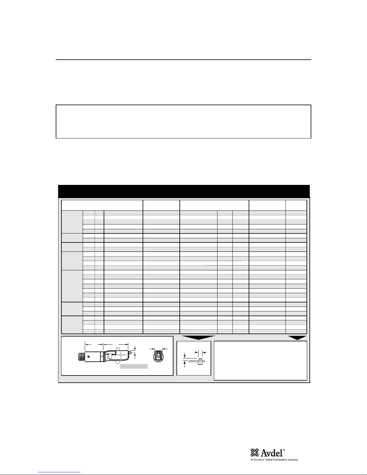
5
Tool S p ecif i c atio n s
Specifications
Air Pressure Minimum - Maximum 5-7 bar (72.5 - 101.5 psi)
Free Air Volume Required @ 5.5 bar 4.3 litres (0.15 cuft)
Stroke Minimum 26 mm (1.02 in)
Pull Force @ 5.5 bar 12.9 kN (2900 lbf)
Cycle time Approximately 1.2 second
Noise Level 75 dB(A)
Weight Without nose equipment 2.35 kg (5.17 lb)
Vibration Less than 2.5 m/s2 (8.2 ft/s2)
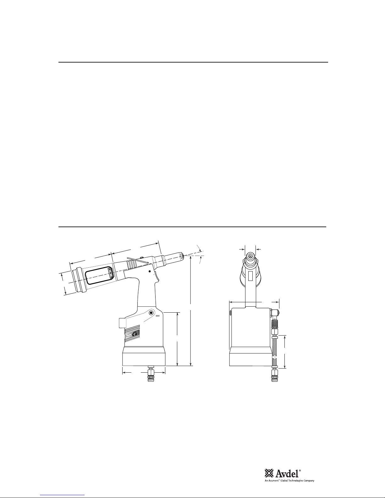
30
12°30'
134
128
152
150
316
145
116
70
3
Dimensions in millimetres.
Tool M e asur emen t s
Englis h

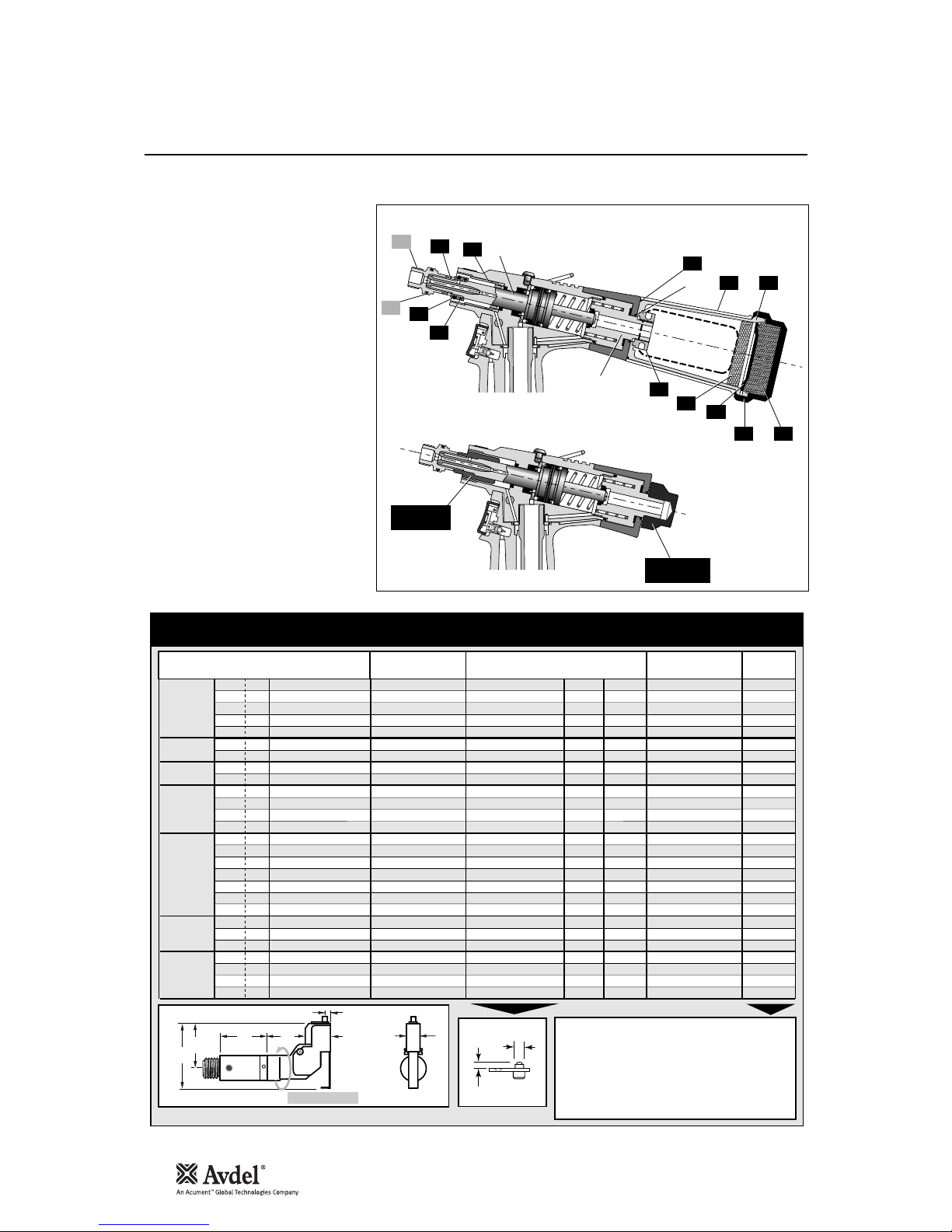
6
Intent of Use
G3 HD is a hydro-pneumatic tool designed to
place Avdel®breakstem fasteners at high
speed making it ideal for batch or flow-line
assembly in a wide variety of applications
throughout all industries. It can place all
fasteners listed below.
The tool features an adjustable vacuum
system for fastener retention and trouble
free collection of the spent stems
regardless of tool orientation. See the
‘Operating Procedure’ on page 7, for
adjustment instructions.
A complete tool is made up of three
separate elements which will be supplied
individually. See diagram below.
NOSE EQUIPMENT MUST BE FITTED AS
DESCRIBED ON PAGE 8.
FASTENER
NAME
MM
IN
FASTENER SIZE ( )
AVEX
®
STAVEX
®
AVINOX
®
AVIBULB
®
ETR
BULBEX
®
T-LOK
®
AVDEL® SR
MONOBOLT
®
INTERLOCK
®
TLR
®
AVTAINER
®
AVDEL
®
MBC
MBC/LC
AVSEAL
®
Q
™ RIVET
T
™ RIVET
CHERRYMATE™
KLAMPTITE™
3 3.2 4.0 4.3 4.8 5 5.2 6 6.4 6.5 7 8 9 9.5 10
–1/85/32 –3/16 – – –1/4 – – – –3/8 –
●
●
●
●
● ● ● ● ●
●
●
●
●
●
●
●
●
●
●
●
●
●
●
●
●
●
●
●
●
●
●
●
●
●
●
●
●
●
●
●
●
●
●
●
●
●
●
●
●
●
●
●
●
●
●
●
●
●
COMPLE TE TO OL
71221-00 . . .
*
BASE TOOL
1
1
2
3
1
NOSE A SSEMB LY
NOSE TIP
2
71221-02000
71210-15000
see note 3
2
3
+ + =
3
3
3
The part number of the base tool remains the same whichever nose assembly, or nose tip is fitted. See the General Assembly
pages 22-23. If a swivel head is fitted, the same base tool must be adapted. See details page 14.
The nose tip part number relates to a specific fastener. If access to the application is
restricted, some extended nose tips are available. See page 9 for selection table.
This single nose assembly will allow placing of non-aerospace fasteners by simply selecting the appropriate nose
tip from the range of type 1 nose tips. Other nose assemblies are available for applications with restricted
access, for aerospace and special fasteners. See tables pages 10-11. A nose assembly can be substituted by a
swivel head (see pages 13-15). In this case the nose tip is part of the swivel head.
* ADD 3 DIGITS FROM THE LAST
COLUMN OF A NOSE TIP TABLE
ON PAGE 9, 10 0R 11.
FOR TOOLS WITH SWIVEL HEADS
USE TABLE PAGES 13-14.
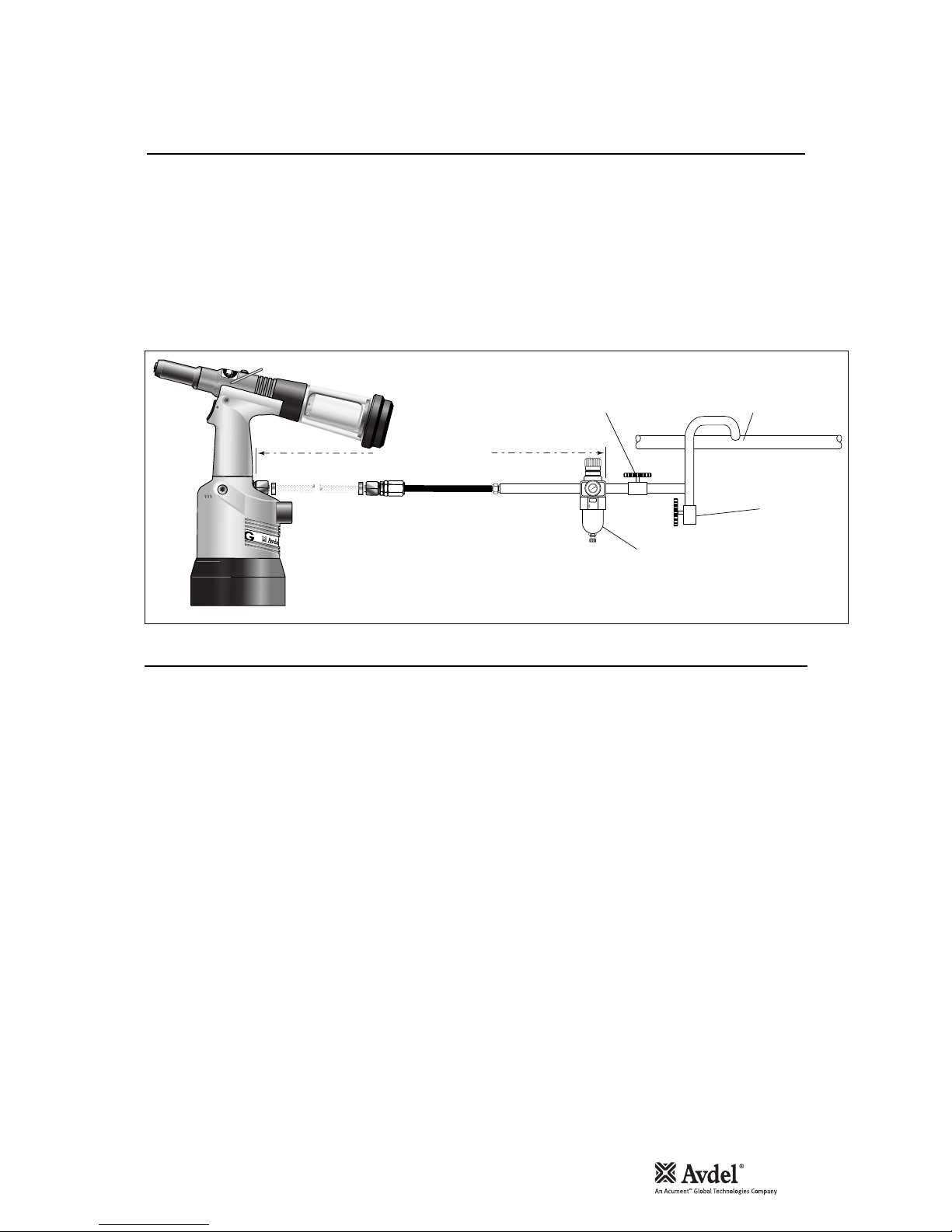
7
All tools are operated with compressed air at an optimum pressure of 5.5 bar. We recommend the use of pressure regulators and
automatic filtering systems on the main air supply. These should be fitted within 3 metres of the tool (see diagram below) to ensure
maximum tool life and minimum tool maintenance.
Air supply hoses should have a minimum working effective pressure rating of 150% of the maximum pressure produced in the system
or 10 bar, whichever is the highest. Air hoses should be oil resistant, have an abrasion resistant exterior and should be armoured where
operating conditions may result in hoses being damaged. All air hoses MUST have a minimum bore diameter of 6.4 millimetres or
1
/4
inch.
Read servicing daily details page 17.
8
6
4
2
0
1
0
1
2
14
1
6
TAKE OFF POINT
FROM
MAIN SUPPLY
STOP COCK
(USED DURING MAINTENANCE
OF FILTER/REGULATOR OR LUBRICATION UNITS)
MAIN SUPPLY
DRAIN POINT
PRESSURE REGULATOR
AND FILTER (DRAIN DAILY)
3 METRES MAXIMUM
3
• Ensure that either the correct nose assembly or swivel head
suitable for the fastener is fitted (see pages 8-11 and 13-15).
• Connect the tool to the air supply.
• Insert the fastener stem into the nose of the tool. If using a nose
assembly, the fastener should remain held in by the vacuum
system. If not, adjust the vacuum extraction rotary valve 60.
• If using a swivel head, the vacuum extraction is disabled but the
jaws themselves will grip the fastener.
• Bring the tool with the fastener to the application so that the
protruding fastener enters squarely the hole of the application.
• Fully actuate the trigger. The tool cycle will broach the fastener
and with standard nose assemblies the broken stem will be
projected to the rear of the tool .
ADJUSTING THE VACUUM EXTRACTION
• Using a screwdriver, turn rotary valve 60 until the air flow at
the rear of the tool ceases.
• With the nose of the tool pointing downwards, insert a
fastener into the nose and hold it into position.
• Turn the rotary valve either way until there is sufficient suction
to retain the fastener.
Item numbers in bold refer to the general assembly drawing and parts list on pages 22-23.
Putting into Service
Ai r Supp l y
Op e ratin g Pro cedu re
Englis h

8
Nose Assemblies
I M P O R T A N T
Nose assemblies do NOT include nose tips. Nose tips must be ordered separately.
A complete tool must always be fitted with the correct nose assembly and nose tip for your fastener and must be ordered separately,
refer to the ‘NOSE TIPS’ tables on pages 9-11.
If your application presents no access restriction use a type ‘1’ nose tip unless you are placing aerospace fasteners which requires a
type ‘3’ nose tip or Avtainer
®
fasteners a type 5 nose tip.
Dimensions ‘A’ and ‘B’ below will help you assess the suitability of a particular nose tip.
You should also check that the dimensions of the nose casing will not restrict access to your application. If access is restricted type
‘2’ nose tips are available for some fasteners. Refer to the table on page 10.
It is essential that nose assembly and nose tip are compatible with the fastener prior to operating the tool.
The type 4 is an alternative to place
1
/4 in Monobolt®. See respective table.
Swivel heads are available as an alternative to nose assemblies as well as an extension when further reach is required. See page 1216 in the ‘Accessories’ section.
Nose assemblies should be serviced at weekly intervals. You should hold some stock of all internal components of the nose assembly and
nose tips as they will need regular replacement.
• Remove the nose equipment using the reverse procedure to the ‘Fitting instructions’.
• Any worn or damaged part should be replaced.
• Clean and check wear on jaws.
• Ensure that neither the jaw spreader nor the front spring guide is distorted.
• Check spring 7 is not distorted.
• Assemble according to fitting instructions above.
I M P O R T A N T
The air supply must be disconnected when fitting or removing nose assemblies.
Item numbers in bold refer to nose assembly components in all 5 nose tip tables.
• Lightly coat jaws 4 with Moly lithium grease*.
• Drop jaws 4 into jaw housing 3 or chuck collet 9 depending on which nose assembly you are using.
• Insert jaw spreader 5 into jaw housing 3 or insert front spring guide 10 into chuck collet 9.
• Locate buffer 6 on jaw spreader 5.
• Locate spring 7 onto jaw spreader 5 or onto front spring guide 10.
• Screw rear spring guide 11 into chuck collet 9.
• Fit locking ring 8 onto the jaw spreader housing of the tool.
• Holding tool pointing down, screw the assembled jaw housing or chuck collet onto the jaw spreader housing and tighten with spanner*.
• Screw the nose tip into nose casing 1 and tighten with spanner*.
• Place nose casing 1 over jaw housing 3 or chuck collet 9 and screw onto the tool, tightening with spanner*.
* Item included in the G3 service kit. For complete list see page 19.
Fi t ting I nstru c t ions
Se r v ing I n struc t ions

9
1
In inches then in millimetres.
2
Head forming nose tips for use with countersunk heads
ONLY.
3
Long nose tip for deep placing
T Y P E 1
N O S E T I P S
N O S E A S S E M B L Y
part nº 71210-15000
F A S T E N E R
MATERIAL
Ø
1
N O S E T I P ( m m )
see
belo w
PART Nº 'A' 'B'NAME
Al All oy
Steel
Al All oy
Al All oy
Al All oy
Steel
Al All oy
Al All oy
Al All oy
Steel
Al All oy
Al All oy
Any
Al All oy
Al All oy
Al All oy
Al All oy
Al All oy
Al All oy
Al All oy
Al All oy
Al All oy
Al All oy
Al All oy
Al All oy
Al All oy
Al All oy
Al All oy
Al All oy
Al All oy
Al All oy
Al All oy
Al All oy
Stainl ess S teel
Stainl ess S teel
Stainl ess S teel
Steel
Steel
Steel
Steel
Steel
Steel
Any
Any
Any
Any
Any
Any
Steel
Steel
Steel
Steel
Steel
Stainl ess S teel
Stainl ess S teel
Stainl ess S teel
Any
Any
Any
Any
Any
Any
Any
Any
Al All oy
Al All oy
Al All oy/St eel
Al All oy/St eel
Al All oy
Al All oy
Al All oy/St eel
Al All oy/St eel
1
/
8
1
/
8
1
/
8
–
5
/
32
5
/
32
5
/
32
3
/
16
3
/
16
3
/
16
3
/
16
1
/
4
3
/
16
5
/
32
3
/
16
–
–
–
–
–
–
–
–
–
–
–
–
–
–
–
–
3
/
16
1
/
4
1
/
8
5
/
32
3
/
16
–
3
/
16
1
/
8
5
/
32
3
/
16
–
1
/
8
5
/
32
3
/
16
3
/
16
1
/
4
3
/
16
1
/
8
5
/
32
3
/
16
3
/
16
3
/
16
1
/
8
5
/
32
3
/
16
1
/
8
5
/
32
3
/
16
1
/
4
3
/
16
1
/
4
3
/
16
1
/
4
3
/
16
3
/
16
3
/
16
3
/
16
1
/
4
1
/
4
1
/
4
1
/
4
6.35
3.3
2.9
6.35
3.3
2.8
3.3
2.8
3.3
3.3
4.1
3.3
4.1
3.3
2.8
4.9
6.9
4.7
6.9
5.3
7.2
5.4
7.3
5.4
7.3
5.5
7.3
5.6
7.3
5.6
7.3
4.1
4.4
3.3
2.8
4.8
3.3
3.3
3.3
2.8
4.8
3.3
6.35
3.3
5.7
5.7
3.3
2.8
3.3
2.8
2.8
3.3
2.8
3.3
2.8
2.8
6.35
3.3
3.3
3.3
3.3
3.3
4.8
4.8
6.35
6.35
6.35
6.35
6.65
6.65
6.65
6.65
12.7
12.7
12.7
12.7
12.7
12.7
12.7
12.7
19.0
12.7
12.7
12.7
12.7
12.7
12.7
12.7
12.7
12.7
12.7
12.7
12.7
12.7
12.7
12.7
12.7
12.7
12.7
12.7
12.7
12.7
12.7
12.7
12.7
12.7
12.7
12.7
12.7
12.7
12.7
12.7
12.7
12.7
12.7
12.7
12.7
12.7
12.7
12.7
12.7
12.7
12.7
19.0
12.7
12.7
12.7
12.7
12.7
12.7
12.7
12.7
12.7
12.7
12.7
12.7
12.7
12.7
12.7
12.7
12.7
12.7
12.7
12.7
7121 0-05002
7121 0-16070
0734 0-06401
2
7121 0-05002
7121 0-16070
0738 1-04701
0734 0-06501
2
0738 1-04701
0734 0-04800
0749 0-04401
0734 0-06601
2
0761 2-02001
7121 0-16020
7121 0-16070
0738 1-04701
7121 0-16001
7121 0-16006
3
7121 0-16002
7121 0-16007
3
7121 0-16003
7121 0-16008
3
7121 0-16004
7121 0-16009
3
7121 0-16005
7121 0-16010
3
7122 0-16006
7122 0-16011
3
7122 0-16007
7122 0-16012
3
7122 0-16008
7122 0-16013
3
0760 5-00220
7122 0-16080
7121 0-16070
0738 1-04701
0749 8-01401
0734 0-06201
0734 0-06201
7121 0-16070
0738 1-04701
0749 8-01401
0761 2-02001
7121 0-05002
7121 0-16070
0734 8-07001
7121 0-16050
7122 0-60001
0738 1-04701
7121 0-16070
0738 1-04701
0738 1-04701
0734 0-04800
0738 1-04701
7121 0-16070
0738 1-04701
0738 1-04701
7121 0-05002
0734 0-06201
0734 0-06201
0761 2-02001
0734 0-06201
0761 2-02001
7122 0-16060
7122 0-16061
703- A-25-6TA
703- B-21
703- A-25-6T
703- B-26
743- A-25-8TA
703- B-21
743- A-25-8T
743- B-26
3.2
3.2
3.2
3
4.0
4.0
4.0
4.8
4.8
4.8
4.8
6.4
4.8
4.0
4.8
4
4
5
5
6
6
6.5
6.5
7
7
8
8
9
9
10
10
4.8
6.4
3.2
4.0
4.8
4.3
4.8
3.2
4.0
4.8
6
3.2
4.0
4.8
4.8
6.4
4.8
3.2
4.0
4.8
4.8
4.8
3.2
4.0
4.8
3.2
4.0
4.8
6.4
4.8
6.4
4.8
6.4
4.8
4.8
4.8
4.8
6.4
6.4
6.4
6.4
AVEX
®
Large flange
MONOBOLT
®
BULBEX
®
AVSEAL
®
TLR
®
AVINOX® II
T-LOK
®
AVIBULB
®
AVDEL® SR
Countersunk
INTERLOCK
®
STAVEX
®
Large flange
Countersunk
Q™ RIVET
CHERRYMATE™
KLAMPTITE™
T™ RIVET
Large flange
Large flange
Large flange
Large flange
… 0 0 1
… 0 0 4
… 0 0 3
… 0 0 1
… 0 0 4
… 0 1 0
… 0 0 9
… 0 1 0
… 0 1 6
… 0 1 7
… 0 1 5
… 0 2 1
… 2 0 0
… 0 0 4
… 0 1 0
… 1 6 0
… 1 8 0
… 1 6 1
… 1 8 1
… 1 6 2
… 1 8 2
… 1 6 3
… 1 8 3
… 1 6 4
… 1 8 4
… 1 6 5
… 1 8 5
… 1 6 6
… 1 8 6
… 1 6 7
… 1 8 7
… 1 4 0
… 1 4 1
… 0 0 4
… 0 1 0
… 0 8 2
… 1 2 0
… 1 2 0
… 0 0 4
… 0 1 0
… 0 8 2
… 0 2 1
… 0 0 1
… 0 0 4
… 0 6 2
… 0 6 4
… 0 6 3
… 0 1 0
… 0 0 4
… 0 1 0
… 0 1 0
… 0 1 6
… 0 1 0
… 0 0 4
… 0 1 0
… 0 1 0
… 0 0 1
… 1 2 0
… 1 2 0
… 0 2 1
… 1 2 0
… 0 2 1
… 4 3 0
… 4 3 5
… 3 8 0
… 3 8 1
… 3 8 3
… 3 8 4
… 3 8 5
… 3 8 6
… 3 8 7
… 3 8 8
A
B
ITEM DESCRIPTION PART Nº
1 NOSE CASING 07340-00306
2 'O' RING 07003-00067
3 JAW HOUSING 07340-00304
4 JAWS 71210-15001
5 JAW SPREADER 07498-04502
6 BUFFER 71210-05001
7 SPRING 07500-00418
8 LOCKING RING 07340-00327
* In ADDITION to the nose assembly shown below,
an extra long nose assembly is available to place
1
/4" Monobolt® in applications with restricted
access. See type 4 NOSE TIP table.
COMPLETE TOOL
PART NUMBER :
precede with
71221-00
8 7 6 5 4 23 1
61
22.9
Nose Assemblies
Englis h

10
Nose Assemblies
1
In inches then in millimetres.
F A S T E N E R
MATERIAL
Ø
1
N O S E T I P ( m m )
see
bel o w
PART Nº 'A' 'B'NAME
Al All oy
Steel
Al All oy
Steel
Al All oy
Steel
Al All oy
Al All oy
Steel
Steel
Steel
Steel
Steel/ Brass
Any
Any
Any
1
/
8
1
/
8
5
/
32
5
/
32
3
/
16
3
/
16
5
/
32
3
/
16
–
3
/
16
1
/
8
5
/
32
5
/
32
1
/
8
5
/
32
3
/
16
12. 95
11. 4
11. 4
10. 0
10. 0
11. 8
11. 4
10. 0
10. 0
10. 0
11. 4
10. 0
10. 0
12. 95
11. 4
11. 4
9.5
9.5
9.5
12. 7
12. 7
12. 7
9.5
12. 7
12. 7
12. 7
9.5
12. 7
12. 7
9.5
9.5
9.5
073 40-0280 5
073 40-0280 6
073 40-0280 6
073 40-0280 7
073 40-0280 7
073 40-0730 1
073 40-0280 6
073 40-0280 7
072 41-0710 1
072 41-0710 1
073 40-0280 6
073 40-0280 7
073 40-0280 7
073 40-0280 5
073 40-0280 6
073 40-0280 7
3.2
3.2
4.0
4.0
4.8
4.8
4.0
4.8
4.3
4.8
3.2
4.8
5.2
3.2
4.0
4.8
AVEX
®
BULB EX
®
T-LO K
®
AVIB UL B
®
ETR
T
™
RIVET
… 0 0 2
… 0 0 8
… 0 0 8
… 0 1 4
… 0 1 4
… 0 1 8
… 0 0 8
… 0 1 4
… 1 2 1
… 1 2 1
… 0 0 8
… 0 1 4
… 0 1 4
… 0 0 2
… 0 0 8
… 0 1 4
ITEM DESCRIPTION PART Nº
1 NOSE CASING 07340-02804
2 'O' RING 07003-00067
3 JAW HOUSING 07340-00304
4 JAWS 71210-15001
5 JAW SPREADER 07498-04502
6 BUFFER 71210-05001
7 SPRING 07500-00418
8 LOCKING RING 07340-00327
COMPLETE TOOL
PART NUMBER :
precede with
71221-00
N O SE A S S E M B L Y
part nº 71210-15200
A
B
TYPE 2 NO SE T IP S AR E EXTENDED
TO AL LO W AC CE SS I NT O
APPLI CA TI ON S WH ER E TYPE 1
NOSE TI PS W IL L NO T REACH.
T Y P E 2
N O S E T I P S
8 7 6 5 4 23
1
58.3
22.9
T Y P E 3
N O S E T I P S
COMPLETE TOOL
PART NUMBER :
precede with
71221-00
1
56.3
22.9
1
In inches then in millimetres.
O
Oversize
N O SE A S S E M B L Y
part nº 71210-15300
ITEM DESCRIPTION PART Nº
1 NOSE CASING 07344-02001
2 'O' RING 07003-00067
3 JAW HOUSING 07340-00304
4 JAWS 71210-15001
5 JAW SPREADER 07498-04502
6 BUFFER 71210-05001
7 SPRING 07500-00418
8 LOCKING RING 07340-00327
TYP E 3 N O S E T I P S A R E S P E C I F ICALLY FOR T H E A E R O S P A C E
FAS T E N E R S L I S T E D B E L O W .
F A S T E N E R
MATERIAL
Ø
1
N O S E T I P ( m m ) se e
bel o w
PART Nº 'A' 'B'NAME
Al All oy
Al All oy
O
Stainl ess Steel
Al All oy
Al All oy
O
Stainl ess Steel
Al All oy
Al All oy
O
Stainl ess Steel
Any
Any
Any
Any
Any
Any
1
/
8
1
/
8
1
/
8
5
/
32
5
/
32
5
/
32
3
/
16
3
/
16
3
/
16
1
/
8
5
/
32
3
/
16
1
/
8
5
/
32
3
/
16
2.5
2.5
3.3
2.5
2.5
3.3
2.5
2.5
2.4
4.8
5.0
5.1
4.6
4.6
4.6
12. 7
12. 7
12. 7
12. 7
12. 7
12. 7
12. 7
12. 7
12. 7
12. 7
12. 7
12. 7
12. 7
12. 7
12. 7
712 10-1603 0
712 10-1603 1
712 10-1603 2
712 10-1603 3
712 10-1603 4
712 10-1603 5
712 10-1603 6
712 10-1603 7
712 20-1603 8
073 40-0670 1
073 40-0680 1
073 40-0690 1
073 44-0470 1
073 44-0470 1
073 44-0470 1
3.2
3.2
3.2
4.0
4.0
4.0
4.8
4.8
4.8
3.2
4.0
4.8
3.2
4.0
4.8
AV D EL
®
MB C
MB C L/ C
… 2 8 3
… 2 8 4
… 2 8 5
… 2 8 8
… 2 8 9
… 2 9 0
… 2 9 3
… 2 9 4
… 2 9 5
… 3 0 0
… 3 0 5
… 3 1 0
… 3 2 0
… 3 2 0
… 3 2 0
A
B
8 7 6 5 4 23

11
Nose Assemblies
T Y P E 5
N O S E T I P
COMPLETE TOOL
PART NUMBER :
precede with
71221-00
1
1
In inches then in millimetres
N O SE A S S E M B L Y part nº 71220-15500
ITEM DESCRIPTION PART Nº
1 NOSE CASING 07498-00501
2 'O' RING 07003-00067
9 CHUCK COLLET 07498-00801
4 JAWS 07220-02302
10 FRONT SPRING GUIDE 07498-00803
ITEM DESCRIPTION PART Nº
7 SPRING 07500-02005
11 REAR SPRING GUIDE 07498-00503
8 LOCKING RING 07340-00327
12 SIDE EJECTION ADAPTOR 07498-00900
THERE IS ONLY ONE TYPE 5 NOSE
TIP, SPECIFICALLY DESIGNED TO
PLACE AVTAINER
®
FASTENERS WITH
THIS SPECIAL NOSE ASSEMBLY.
F A S T E N E R
MATERIAL
Ø
1
N O S E T I P ( m m ) se e
bel o w
PART Nº 'A' 'B'NAME
Steel
3
/
8
4.119. 1
074 98-0080 2
9.6
AV T AIN E R
®
… 2 4 3
98.5
20.6
90
12 11 7 10 4 298
A
B
28.6
N O SE A S S E M B L Y
part nº 71230-15800
A
B
8 7 6 5 4 23 1
61
22.9
.. . 2 0 1
.. . 2 6 1
1
In inches then in millimetres
F A S T E N E R
MATERIAL
Ø
1
N O S E TI P ( m m ) s ee
a b o ve
PART Nº 'A' 'B'NAME
1
/
4
1
/
4
MONOBOLT
®
INTERLOCK
®
T Y P E 6
N O S E T I P S
ITEM DESCRIPTION PART Nº
1 NOSE CASING 07340-00306
2 'O' RING 07003-00067
3 CHUCK COLLET 07612-02003
4 JAWS 07612-02002
5 JAW SPREADER 07498-04502
6 BUFFER 07498-03003
7 SPRING 07500-00418
8 LOCKING RING 07340-00327
Any
Any
4.1
3.6
14. 3
14. 3
712 20-1602 1
076 12-0200 1
6.4
6.4
COMPLETE TOOL
PART NUMBER
PRECEDED WITH:
71221-00
T Y P E 4
N O S E T I P
COMPLETE TOOL
PART NUMBER :
precede with
71221-00
1
1
In inches then in millimetres
N O SE A S S E M B L Y part nº 71220-15400
ITEM DESCRIPTION PART Nº
1 NOSE CASING 07498-00501
2 'O' RING 07003-00067
9 CHUCK COLLET 07498-00502
4 JAWS 07497-03002
ITEM DESCRIPTION PART Nº
10 FRONT SPRING GUIDE 07498-00507
7 SPRING 07500-02005
11 REAR SPRING GUIDE 07498-00503
8 LOCKING RING 07340-00327
FIT TE D TO TH IS LO NG NO SE
ASS EM BLY, TH E TYP E 4 N OS E TIP
WIL L ALLOW T HE PL AC ING O F
1
/4 " MONOB OL T
®
FA ST ENERS
IN AP PLICA TI ONS R EQ UIR IN G
VER Y DEEP AC CESS.
F A S T E N E R
MATERIAL
Ø
1
N O S E T I P ( m m ) se e
bel o w
PART Nº 'A' 'B'NAME
Steel
1
/
4
4.114. 3
712 20-1602 1
6.4
MONOBOLT
®
… 2 0 2
11 7 10 4 298
A
B
20.6
98.5
Englis h
12
St e m Def l ector
Accessories
ADAPTOR NUT
71210-20101
STEM DEFLECTOR
07340-00342
The stem deflector is a very simple alternative to the standard
stem collector and allows access in restricted areas. To
replace the stem collector with the stem deflector proceed as
follows:
• Unscrew retaining nut 22 by inserting a 3 millimetre
diameter rod into one of the holes.
• Remove retaining nut 22 and the stem collector assembly,
items 18, 19, 20, 21, 45, 62 and 63.
• Screw the adaptor nut onto end cap 23.
• Push the boss end of the stem deflector into the internal
groove of the adaptor nut.
• Rotate the stem deflector until the aperture faces away
from the operator and other person(s) in the vicinity.
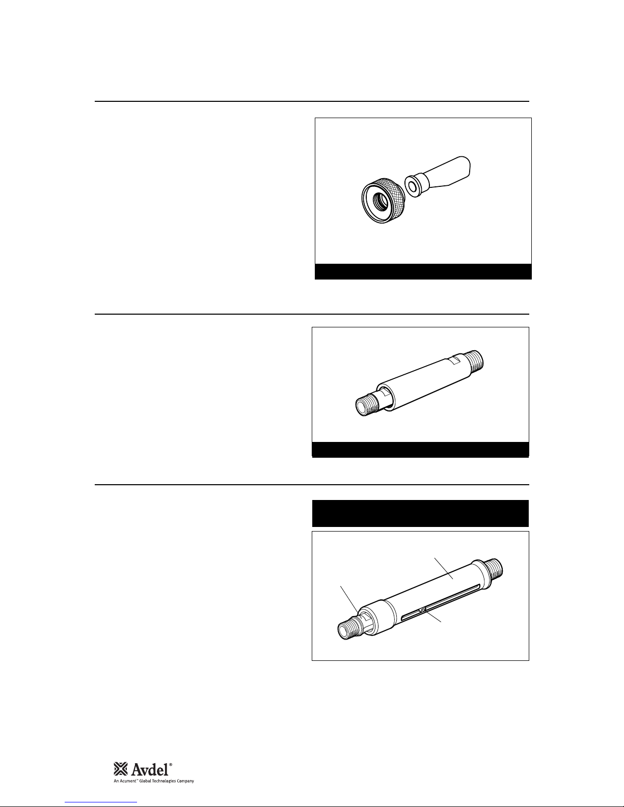
Item numbers in bold refer to the general assembly drawing and parts list on pages 22-23.
INNER
71210-20301
OUTER
71210-20302
STEM DEFLECTOR: 71210-20100
EXTENSION: 71210-20300
INNER
EXTENSION
OUTER CASING
8-32 x 1/4" SOCKET
CAP HEAD SCREW
Part number: 07498-00900
for fasteners with a stem larger than 3.1 mm (1/8") Ø
Fitted between the tool and the nose assembly the extension
gives an extra reach of 76mm, ideal for use in deep narrow
applications.
• To fit the extension, remove any nose assembly
components.
• Screw the inner extension to jaw spreader housing 1.
• Screw the outer onto head assembly 4.
• Fit the nose assembly onto the extension.
Fitted between the tool and the nose assembly, the side ejector
forces fastener stems to eject at the front of the tool and gives
an extra reach of 90mm.
It cannot be used in conjunction to a swivel head. Select the
correct part number (below right) according to the stem diameter
of the fastener.
For greater ease of use, it is recommended that the stem
collector or deflector is replaced with safety cap part number
71210-20201 as used with swivel heads. See page 14 for fitting
instructions, but note that the stop nut is not fitted in this case.
• To fit the side ejector, remove any nose assembly
components.
• Remove the socket cap screw from the side ejector.
• Screw the inner extension onto jaw spreader housing 1.
• Screw the outer casing onto head assembly 4.
• Replace the socket cap screw securing with Loctite
Screwlock 222, part number 07900-00371.
• Screw the nose assembly onto the side ejector.
Ex t ensio n
Si d e Eje c tor
13
Sw i vel H e ad
Accessories
Instead of a nose assembly, a swivel head can be fitted to a base tool. It allows 360° rotation of the tool about the nose tip and allows
access into many applications otherwise too restrictive. There are two types of swivel heads: the straight swivel head with the nose tip
slightly offset from the centre line of the tool head and the right-angle swivel head with the nose tip on a perpendicular axis to the head
of the tool. See drawings below for dimensions and pages 15-16 for detail.
I M P O R T A N T
PRIOR to fitting a swivel head, the base tool must be adapted. See Preparing the base tool on page 14.
In contrast to nose assemblies part numbers of swivel heads do INCLUDE a nose tip as shown below.
Swivel heads can be ordered on their own or fitted to a base tool forming a complete tool. See table below for part numbers. Jaws
and nose tips vary depending on the fastener to be placed but all other components remain the same within each type of swivel head.
See the ‘capability’ tables below and ‘constant component table’ page 16.
'A’ and ‘B’ dimensions will help you assess the accessibility of your application.
1
In inches then in millimetres.
2
Long nose tip for deep placing.
O
Oversize
F A S T E N E R
MATERIAL
Ø
1
N O S E T I P ( m m )S W I V E L H E A D
PART Nº
J A W S
see
bel o w
'A' 'B'NAME
Al All oy
Steel
Al All oy
Steel
Al All oy
Al All oy
Al All oy
Stainl ess Steel
Stainl ess Steel
Al All oy
Al All oy
Al All oy
Al All oy
Al All oy
Al All oy
O
Stainl ess Steel
Al All oy
Al All oy
O
Al All oy
Al All oy
O
Al All oy
Al All oy
Al All oy
Al All oy
Al All oy
Al All oy
O
Al All oy
1
/
8
1
/
8
5
/
32
5
/
32
3
/
16
5
/
32
3
/
16
1
/
8
5
/
32
–
–
–
–
1
/
8
1
/
8
1
/
8
5
/
32
5
/
32
3
/
16
3
/
16
1
/
8
5
/
32
3
/
16
1
/
8
5
/
32
5
/
32
3
/
16
3.8 1
3.8 1
3.8 1
3.8 1
3.8 1
3.8 1
3.8 1
3.8 1
3.8 1
1.9 5
4.1 1
2.0 0
4.1 1
1.1 7
1.1 7
3.8 1
0.8 4
0.8 4
0.2 5
0.2 5
1.9
2.3 6
2.4 6
2.0 3
2.0 3
2.0 3
2.0 3
7.8 7
7.8 7
7.8 7
7.8 7
7.8 7
7.8 7
7.8 7
7.8 7
7.8 7
6.3 5
6.3 5
7.6 2
7.6 2
5.0 8
5.0 8
5.0 8
6.6
6.6
8.1 3
8.1 3
4.7 5
6.3 5
7.9 2
7.8 7
7.8 7
7.8 7
7.8 7
073 45-0300 0
073 45-0310 0
073 45-0310 0
073 45-0320 0
073 45-0320 0
073 45-0310 0
073 45-0320 0
073 45-0310 0
073 45-0320 0
074 94-0600 0
074 94-0660 0
074 94-0610 0
074 94-0670 0
073 45-0330 0
074 94-0360 0
074 94-0300 0
073 45-0340 0
074 94-0370 0
073 45-0350 0
074 94-0380 0
073 45-0400 0
073 45-0410 0
073 45-0420 0
073 45-0470 0
073 45-0470 0
073 45-0480 0
073 45-0480 0
PART Nº
073 40-0021 3
073 40-0021 3
073 40-0021 3
074 90-0460 2
074 90-0460 2
073 40-0021 3
074 90-0460 2
073 40-0021 3
074 90-0460 2
073 40-0021 3
073 40-0021 3
073 40-0021 3
073 40-0021 3
073 40-0022 9
073 40-0022 9
073 40-0021 3
073 40-0022 9
073 40-0022 9
074 98-0440 1
074 98-0440 1
073 40-0022 9
073 40-0022 9
074 98-0440 1
073 40-0022 9
073 40-0022 9
074 98-0440 1
074 98-0440 1
PART Nº
073 45-0360 0
073 45-0370 0
073 45-0370 0
073 45-0380 0
073 45-0380 0
073 45-0370 0
073 45-0380 0
073 45-0370 0
073 45-0380 0
074 94-0600 1
074 94-0660 1
2
074 94-0610 1
074 94-0670 1
2
073 45-0330 1
074 94-0360 1
074 94-0301 1
073 45-0340 1
074 94-0370 1
073 45-0350 1
074 94-0380 1
071 65-0070 1
071 65-0070 2
071 65-0070 3
073 45-0470 1
073 45-0470 1
073 45-0470 1
073 45-0470 1
3.2
3.2
4.0
4.0
4.8
4.0
4.8
3.2
4.0
4
4
5
5
3.2
3.2
3.2
4.0
4.0
4.8
4.8
3.2
4.0
4.8
3.2
4.0
4.0
4.8
AVEX
®
BULB EX
®
AVIN OX
®
AVSE AL
®
AV D EL
®
MB C
MB C L/ C
… 0 0 1
… 0 0 4
… 0 0 4
… 0 1 0
… 0 1 0
… 0 0 4
… 0 1 0
… 0 0 4
… 0 1 0
… 1 6 0
… 1 8 0
… 1 6 1
… 1 8 1
… 2 8 3
… 2 8 4
… 2 8 5
… 2 8 8
… 2 8 9
… 2 9 3
… 2 9 4
… 3 0 0
… 3 0 5
… 3 1 0
… 3 2 0
… 3 2 0
… 3 2 7
… 3 2 7
COMPLETE TOOL PART NUMBER :
precede with 71221-30
(the stop nut and safety cap are included)
IMPORTANT: by opposition to complete tools
with nose assemblies, those fitted with swivel heads
include the nose tip as a part of the head.
S TR A IG H T S WI V EL HE A D c ap a bi l it y
A
B
360
° r
otat
i
on
56
92
6
20
Englis h
14
Pr epar i n g th e Base To o l
Accessories
1
In inches then in millimetres.
2
Long nose tip for deep placing.
O
Oversize
F A S T E N E R
MATERIAL
Ø
1
N O S E T I P ( m m )SW IV E L H E A D
PART Nº
J A W S
see
bel o w
'A' 'B'NAME
Al All oy
Steel
Al All oy
Steel
Al All oy
Al All oy
Al All oy
Stainl ess Steel
Stainl ess Steel
Al All oy
Al All oy
Al All oy
Al All oy
Al All oy
Al All oy
O
Stainl ess Steel
Al All oy
Al All oy
O
Al All oy
Al All oy
O
Al All oy
Al All oy
Al All oy
Al All oy
Al All oy
Al All oy
O
Al All oy
1
/
8
1
/
8
5
/
32
5
/
32
3
/
16
5
/
32
3
/
16
1
/
8
5
/
32
–
–
–
–
1
/
8
1
/
8
1
/
8
5
/
32
5
/
32
3
/
16
3
/
16
1
/
8
5
/
32
3
/
16
1
/
8
5
/
32
5
/
32
3
/
16
3.8 1
3.8 1
3.8 1
3.8 1
3.8 1
3.8 1
3.8 1
3.8 1
3.8 1
1.9 5
4.1 1
2.0 0
4.1 1
1.1 7
1.1 7
3.8 1
0.8 4
0.8 4
0.2 5
0.2 5
1.9
2.3 6
2.4 6
2.0 3
2.0 3
2.0 3
2.0 3
7.8 7
7.8 7
7.8 7
7.8 7
7.8 7
7.8 7
7.8 7
7.8 7
7.8 7
6.3 5
6.3 5
7.6 2
7.6 2
5.0 8
5.0 8
5.0 8
6.6
6.6
8.1 3
8.1 3
4.7 5
6.3 5
7.9 2
7.8 7
7.8 7
7.8 7
7.8 7
073 46-0300 0
073 46-0310 0
073 46-0310 0
073 46-0320 0
073 46-0320 0
073 46-0310 0
073 46-0320 0
073 46-0310 0
073 46-0320 0
074 95-0400 0
074 95-0470 0
074 95-0410 0
074 95-0480 0
073 46-0330 0
074 95-0360 0
074 95-0300 0
073 46-0340 0
074 95-0370 0
073 46-0350 0
074 95-0380 0
073 46-0400 0
073 46-0410 0
073 46-0420 0
073 46-0450 0
073 46-0450 0
073 46-0460 0
073 46-0460 0
PART Nº
073 40-0021 3
073 40-0021 3
073 40-0021 3
074 90-0460 2
074 90-0460 2
073 40-0021 3
074 90-0460 2
073 40-0021 3
074 90-0460 2
073 40-0021 3
073 40-0021 3
073 40-0021 3
073 40-0021 3
073 40-0022 9
073 40-0022 9
073 40-0021 3
073 40-0022 9
073 40-0022 9
074 98-0440 1
074 98-0440 1
073 40-0022 9
073 40-0022 9
074 98-0440 1
073 40-0022 9
073 40-0022 9
074 98-0440 1
074 98-0440 1
PART Nº
073 45-0360 0
073 45-0370 0
073 45-0370 0
073 45-0380 0
073 45-0380 0
073 45-0370 0
073 45-0380 0
073 45-0370 0
073 45-0380 0
074 94-0600 1
074 94-0660 1
2
074 94-0610 1
074 94-0670 1
2
073 45-0330 1
074 94-0360 1
074 94-0301 1
073 45-0340 1
074 94-0370 1
073 45-0350 1
074 94-0380 1
071 65-0070 1
071 65-0070 2
071 65-0070 3
073 45-0470 1
073 45-0470 1
073 45-0470 1
073 45-0470 1
3.2
3.2
4.0
4.0
4.8
4.0
4.8
3.2
4.0
4
4
5
5
3.2
3.2
3.2
4.0
4.0
4.8
4.8
3.2
4.0
4.8
3.2
4.0
4.0
4.8
AVEX
®
BULB EX
®
AVIN OX
®
AVSE AL
®
AV D EL
®
MB C
MB C L/ C
… 0 0 1
… 0 0 4
… 0 0 4
… 0 1 0
… 0 1 0
… 0 0 4
… 0 1 0
… 0 0 4
… 0 1 0
… 1 6 0
… 1 8 0
… 1 6 1
… 1 8 1
… 2 8 3
… 2 8 4
… 2 8 5
… 2 8 8
… 2 8 9
… 2 9 3
… 2 9 4
… 3 0 0
… 3 0 5
… 3 1 0
… 3 2 0
… 3 2 0
… 3 2 7
… 3 2 7
COMPLETE TOOL PART NUMBER :
precede with 71221-40
(the stop nut and safety cap are included)
IMPORTANT: by opposition to complete tools
with nose assemblies, those fitted with swivel heads
include the nose tip as a part of the head.
R IG H T- A NG L E S WI V EL HE A D c ap a bi l it y
7
.
6
32
2
0
52
56
7
4
97
A
B
360
° rota tion
1
2
3
5
7
17
23
20
22
21
62
19
63
18
45
66
65
71210-20202
STOP NUT
71210-20201
SAFETY C AP
• Disconnect the air supply.
• Remove any nose assembly items.
• Remove retaining nut 22 and all
elements of the stem collector (items
18, 19, 20, 21, 45, 62, 63). Note that
‘O’ ring 17 remains.
• Replace the above with a safety cap as
shown in drawing opposite.
• Unscrew jaw spreader housing 1 and
remove with ‘O’ ring 2, locknut 3, ‘O’
rings 66 and 65, and seal housing 5.
• Screw stop nut 71210-20202 onto the
front of head piston 7 as far as it will go
by hand.
• Re-fit jaw spreader housing 1 and ‘O’ ring
2.
• Unscrew the stop nut until it locks
against jaw spreader housing 1 and
tighten with spanner.
The tool is now ready to be fitted with a
swivel head. Instructions are on page 15.
Base tool to receive a nose assembly
Base tool to receive a swivel head
15
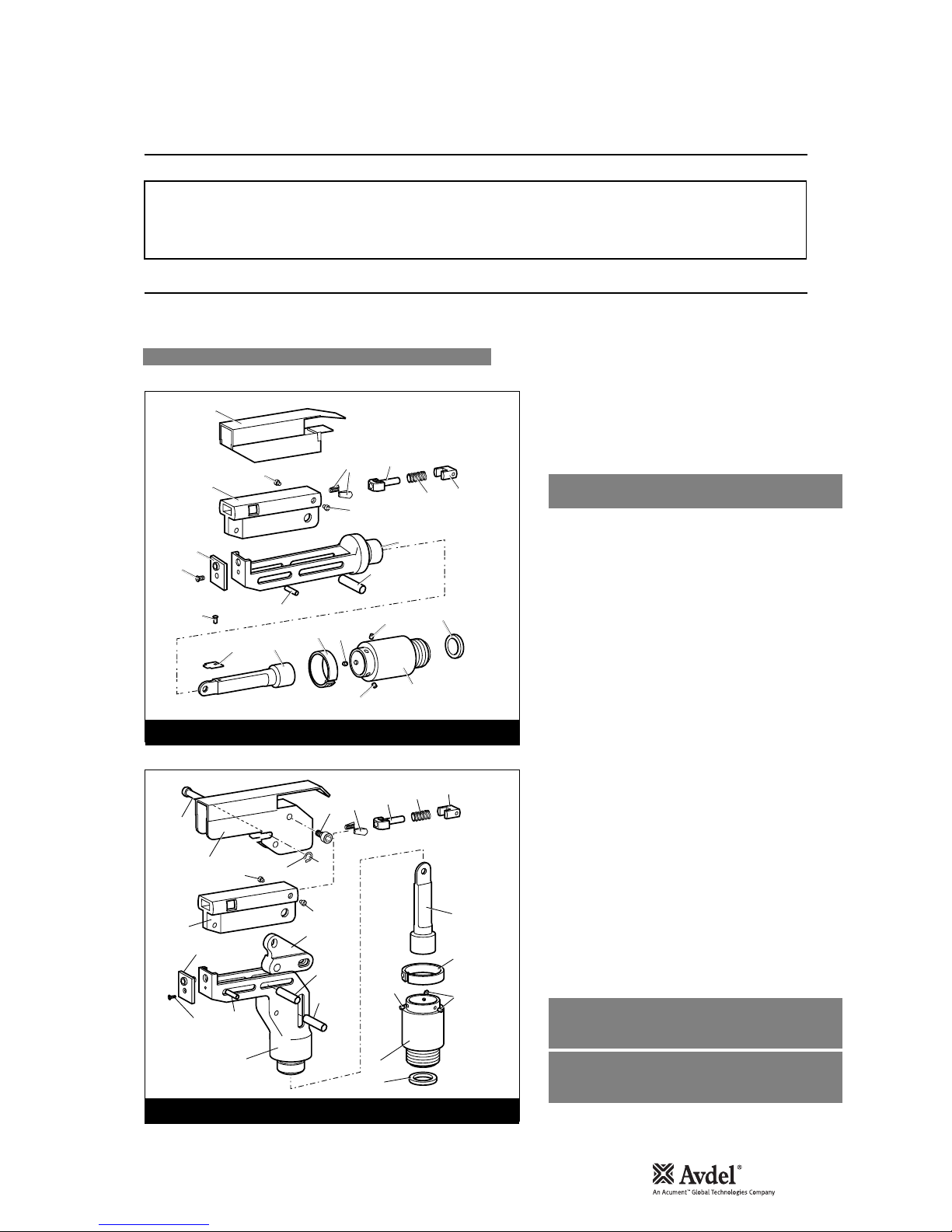
Sw i vel H e ad Fi t t ing I n stru c t ions
Accessories
The following procedure will allow you to assemble and fit either of the swivel heads to the tool. If you order a complete swivel head
rather than individual components, you will only need to start at stage L.
All moving parts should be lubricated. Unless stated otherwise use Moly Lithium grease (details page 17).
When on grey tint, instructions refer only to the right-angle swivel head. Item numbers in bold refer to illustrations below.
The fitting and servicing procedures for both types of head are almost identical. Differences are clearly indicated.
I M P O R T A N T
PRIOR to fitting a swivel head, the base tool must be adapted. See Preparing the base tool opposite.
The air supply must be disconnected when fitting or removing swivel heads.
16
1
3
12
14
13
16
6
5
21
22
11
7
9
8
8
8
10
17
18
19
20
STRAIGHT SWIVEL HEAD
2
1
15
9
8
8
10
7
11
17
23
18
19
20
3
16
16
4
12
14
13
6
6
5
RIGHT-ANGLE HEAD
A Fit locking ring 10 over jaw spreader housing 1.
B Coat screw 13 with thread locking adhesive and use to
secure nose tip 14 onto body 5.
C Lightly lubricate items 17, 18, 19, 20 and insert into jaw
carrier 3 as shown. Secure with screws 16.
D Position lever 4 into body 5 and hold in place with pin 15
through the hole of body 5 (not a slot).
E Lubricate the sides of the jaw carrier assembly and insert
into body 5.
F Lubricate rollers 8 and ENSURE that they will freely rotate in
the holes of adaptor 9. If necessary ream the holes.
G Position spring clip 7 over adaptor 9 past the holes for the
rollers and rotate until the locating peg is aligned with the
corresponding hole in adaptor 9 (smallest hole).
H Fit adaptor 9 over the end of body 5 and drop rollers 8 into
place. Push spring clip 7 over rollers 8.
I Insert spindle 11 through adaptor 9 into jaw carrier 3 until
the hole lines up with slot in body 5. Temporarily hold in place
with pin 6.
J Insert pin 12 through the front slot of body 5 into jaw carrier
3.
K Hold the assembly vertical to prevent all pins dropping and
slide the jaw carrier assembly back and forth a few times to
ensure free movement. Go to M.
L Remove screws 23 (4 off) and guard 1. On a straight swivel
head also remove screw 21 and platform 22.
M Push pin(s) 6 out and let spindle 11 drop out. Screw spindle
11 onto the jaw spreader housing of the tool, leaving the
small screw fixing hole uppermost for straight swivel. Tighten
gently with a tommy bar.
N Screw the assembly over spindle 11 onto the tool handle.
Replace pin(s) 6.
O On straight swivel heads attach platform 22 onto the top of
the spindle with screw 21. Deburr the back end of platform
22 so that it cannot catch on guard 1.
P Snap guard 1 over the assembly, align screw holes in guard
with tapped holes in body assembly.
Q Insert pivot pin 15 through slots in guard and hole in body.
Fit circlip 2 onto pivot pin so that the circlip seats in
groove provided.
R Coat the thread of screws 23 (4 off) with thread locking
adhesive and screw into body assembly securing guard to
body assembly.
Englis h

16
Sw i vel H e ad Se r v icing Instr u ction s
Accessories
5
7
17
18
19
20
Swivel heads should be serviced at weekly intervals.
• Remove the complete head using the reverse procedure to
the ‘Fitting instructions’ omitting step ‘L’.
• If guard 1 is at all damaged it must be replaced by a new
one.
• Any worn or damaged parts should be replaced.
• Pay particular attention to jaw carrier items in the upper il-
lustration opposite as follows:
Check wear on jaws 17.
Check that jaw spreader tube 18 is not distorted.
Check that spring 19 is neither broken or distorted.
Check that spring guide 20 is not damaged.
• Check that spring clip 7 is not distorted. When removing
spring clip 7, use two screwdrivers as shown in the lower
illustration opposite.
• Check for excessive wear on slots of body 5.
• Assemble according to fitting instructions.
While nose tips and jaws will vary for each swivel head, other components remain constant within each type of head. See table below.
For nose tips and jaws part numbers see pages 9-11.
C O N S T A N T C O M P O N E N T S
ITEM STRAIGHT SWIVEL RIGHT-ANGLE SWIVEL
1
2
3
4
5
6
7
8
9
10
11
12
13
15
16
18
19
20
21
22
23
GUARD
CIRCLIP
JAW CARRIER
LEVER
BODY
PIVOT PIN
SPRING CLIP
ROLLER
ADAPTOR
LOCKING RING
SPINDLE
DOWEL PIN
SCREW
PIVOT PIN
SCREW
JAW SPREADER
SPRING
SPRING GUIDE
SCREW
PLATFORM
SCREW
0 7 49 4- 05 00 0
-
0 7 49 4- 03 02 6
0 7 49 4- 03 01 5
0 7 34 3- 02 20 7
0 7 49 5- 03 90 0
0 7 00 7- 00 03 9
0 7 34 5- 03 00 1
0 7 34 5- 03 00 3
0 7 34 5- 03 00 2
0 7 00 7- 00 03 8
0 7 34 2- 02 20 7
0 7 49 4- 03 02 8
0 7 34 6- 03 10 1
0 7 16 5- 00 30 5
0 7 49 4- 03 02 7
0 7 00 1- 00 36 8
0 7 34 5- 00 40 1
-
0 7 49 5- 03 00 3
0 7 00 4- 00 10 5
0 7 49 4- 03 02 6
0 7 49 5- 03 00 4
0 7 49 5- 03 00 2
0 7 34 3- 02 20 7
0 7 49 5- 03 90 0
0 7 00 7- 00 03 9
0 7 34 5- 03 00 1
0 7 34 5- 03 00 3
0 7 34 5- 03 00 2
0 7 00 7- 00 03 8
0 7 34 2- 02 20 7
0 7 34 3- 02 20 7
0 7 49 4- 03 02 8
0 7 34 6- 03 10 1
0 7 16 5- 00 30 5
0 7 49 4- 03 02 7
–
–
0 7 21 0- 00 80 4

17
Servicing the Tool
• Daily, before use or when first putting the tool into service, pour a few drops of clean, light lubricating oil into the air inlet of the tool
if no lubricator is fitted on air supply. If the tool is in continuous use, the air hose should be disconnected from the main air supply
and the tool lubricated every two to three hours.
• Check for air leaks. If damaged, hoses and couplings should be replaced.
• If there is no filter on the pressure regulator, bleed the air line to clear it of accumulated dirt or water before connecting the air
hose to the tool. If there is a filter, drain it.
• Check that the nose assembly or swivel head is correct for the fastener to be placed.
• Check the stroke of the tool meets the minimum specification (page 5). The last step of the 'Priming Procedure' on page 23
explains how to measure the stroke.
• Either a stem collector or a stem deflector must be fitted to the tool unless a swivel head is fitted.
• Ensure that rotary valve 60 is correctly adjusted for fastener retention (see ‘Operating Procedure’ page 7).
• Dismantle and clean the nose assembly with special attention to the jaws. Lubricate with Moly Lithium grease before assembling.
• Check for oil leaks and air leaks in the air supply hose and fittings.
Grease can be ordered as a single item, the part number is shown in the service kit page 19.
First Aid
SKIN:
As the grease is completely water resistant it is best removed with an approved emulsifying skin cleaner.
INGESTION:
Ensure the individual drinks 30ml Milk of Magnesia, preferably in a cup of milk.
EYES:
Irritant but not harmful. Irrigate with water and seek medical attention.
Fire
FLASH POINT: Above 220°C.
Not classified as flammable.
Suitable extinguishing media: CO
2
, Halon or water spray if applied by an experienced operator.
Environment
Scrape up for burning or disposal on approved site.
Handling
Use barrier cream or oil resistant gloves
Storage
Away from heat and oxidising agent.
Item numbers in bold refer to the general assembly drawing and parts list on pages 22-23.
I M P O R T A N T
Read Safety Instructions on page 4.
The employer is responsible for ensuring that tool maintenance instructions are given to the appropriate personnel.
The operator should not be involved in maintenance or repair of the tool unless properly trained.
The tool shall be examined regularly for damage and malfunction.
Da i ly
Weekl y
Mo l y Lit h ium G reas e EP 3 7 5 3 Sa f e ty D a t a
Englis h

Specifications
First Aid
SKIN:
Flush with water. Wipe off.
INGESTION:
No first aid should be needed.
EYES:
Flush with water.
Fire
FLASH POINT: Above 101.1°C. (closed cup)
Explosive Properties: No
Suitable Extinguishing Media: Carbon Dioxide Foam, Dry Powder or fine water spray.
Water can be used to cool fire exposed containers.
Environment
Do not allow large quantities to enter drains or surface waters.
Methods for cleaning up: Scrape up and place in suitable container fitted with a lid. The spilled product produces an extremely
slippery surface.
Harmful to aquatic organisms and may cause long-term adverse effects in the aquatic environment. However, due to the physical
form and water - insolubility of the product the bioavailability is negligible.
Handling
General ventilation is recommended. Avoid skin and eye contact.
Storage
Do not store with oxidizing agents. Keep container closed and store away from water or moisture.
First Aid
SKIN:
No first aid should be needed.
INGESTION:
No first aid should be needed.
EYES:
No first aid should be needed.
INHALATION:
No first aid should be needed.
Fire
FLASH POINT: Above 101.1°C. (closed cup)
Explosive Properties: No
Suitable Extinguishing Media: Carbon Dioxide Foam, Dry Powder or fine water spray.
Water can be used to cool fire exposed containers.
Environment
No adverse effects are predicted.
Handling
General ventilation is recommended. Avoid eye contact.
Storage
Do not store with oxidizing agents. Keep container closed and store away from water or moisture.
Mo l ykote 55m G reas e Safe t y Dat a
Mo l ykote 111 G reas e Safe t y Dat a
18

19
An n ually
Servicing the Tool
PART Nº DESCRIPTIONPART Nº DESCRIPTION
SERVICE KIT : 71210-99990 Spanners are specified in inches and across flats unless otherwise stated
07900-00667 PISTON SLEEVE
07900-00692 TRIGGER VALVE EXTRACTOR
07900-00670 BULLET
07900-00672 'T' SPANNER
07900-00706 'T' SPANNER SPIGOT
07900-00684 GUIDE TUBE
07900-00685 INSERTION ROD
07900-00351 3 MM ALLEN KEY
07900-00469 2.5 MM ALLEN KEY
07900-00158 2 MM PIN PUNCH
07900-00164 CIRCLIP PLIERS
07900-00008
7
/16 x 1/2 SPANNER
07900-00012
9
/16 x 5/8 SPANNER
07900-00015
5
/8 x 11/16 SPANNER
07900-00686 PEG SPANNER
07900-00677 SEAL EXTRACTOR
07900-00698 STOP NUT
07900-00700 PRIMING PUMP
07992-00020 GREASE - MOLY LITHIUM E.P.3753
07992-00075 GREASE - MOLYKOTE 55M
07900-00755 GREASE - MOLYKOTE 111
(or every 500,000 cycles whichever is the soonest)
Annually or every 500,000 cycles the tool should be completely dismantled and new components should be used where worn, damaged
or recommended. All ‘O’ rings and seals should be renewed and lubricated with Molykote 55m grease for pneumatic sealing or Molykote
111 for hydraulic sealing.
For an easy complete service, Avdel is offering a complete service kit.
The airline must be disconnected before any servicing or dismantling is attempted unless specifically instructed otherwise.
It is recommended that any dismantling operation be carried out in clean conditions.
Before proceeding with dismantling, empty the oil from the tool following the first three steps of the 'Priming Procedure' on page 23.
Prior to dismantling the tool it is necessary to remove the nose equipment. For instructions see the nose equipment section, pages 811 or if a swivel head was fitted pages 13-15.
For a complete service of the tool, we advise that you proceed with dismantling of sub-assemblies in the order shown.
After any dismantling REMEMBER to prime the tool and to fit an appropriate nose assembly or swivel head.
• Unscrew retaining nut 22 and remove stem collector assembly, items 20, 18, 19, 21, 62, 63 and 45.
• Remove bottle adaptor assembly 13.
• Using the ‘T’ spanner* remove end cap assembly 23 together with seal 15, ‘O’ ring 14 and lip seal 24.
• Remove spring 24 and spring centralising bush 25.
• Loosen locknut 3 with a spanner* then unscrew jaw spreader housing 1 and ‘O’ ring 2.
• Remove locknut 3 together with 'O' rings 65 and 66 and vacuum sleeve 46.
• Push head piston 7 to the rear and out of head assembly 4 taking care not to damage the head cylinder bore.
• Using circlip pliers* remove seal retainer 26. Push lip seal 8 to the rear and out of head assembly 4 taking care again not to damage the
head cylinder bore.
• Remove seal housing 5 and lip seal 6.
* Item included in G3 service kit.
Item numbers in bold refer to the general assembly drawing and parts list on pages 22-23.
I M P O R T A N T
Read Safety Instructions on page 4.
The employer is responsible for ensuring that tool maintenance instructions are given to the appropriate
personnel.
The operator should not be involved in maintenance or repair of the tool unless properly trained.
The tool should be examined regularly for damage and malfunction.
He a d Ass e mbly
Englis h

Servicing the Tool
• Remove ‘ON/OFF’ valve assembly 55.
• Clamp the body of the inverted tool ACROSS THE AIR INLET BOSSES in a vice fitted with soft jaws.
• Pull off rubber boot 72.
• Using the peg spanner* unscrew base cover 36.
• Unscrew locknuts 68 (2 off) and remove base plate 70.
• Remove liner 41 together with sealing washers 71 (2 off) and 'O' rings 69 (2 off).
• Remove pneumatic piston assembly 38 together with ‘O’ ring 35, lip seal 37 (3 off) and guide ring 31.
Assemble in reverse order.
• Remove pneumatic piston assembly 38 as above.
• Using the ‘T’ spanner* and ‘T’ spanner spigot* unscrew clamp nut 32 and remove it together with top plate 58, tie rods 39 and transfer
tube assembly 40.
• Release the tool from the vice and separate body 34 from handle assembly 28.
• Remove ‘O’ ring 29 from intensifier tube and remove head assembly 4 from handle assembly 28.
• Push out valve seat 59 together with both ‘O’ rings 64 (2 off).
• Remove all components of valve spool assembly 49.
• Remove ‘O’ ring 54 from handle recess.
Assemble in reverse order noting the following points -
• Ensure valve seat is correctly orientated.
• Use Loctite 243 when reassembling Clamp Nut 32, torque to 11ft lb (14.91 Nm).
• Using the 2 millimetre diameter pin punch*, drive trigger pin 44 out and lift off trigger 43.
• Unscrew trigger valve 42 using the trigger valve extractor*.
Assemble in reverse order to dismantling.
I M P O R T A N T
Check the tool against daily and weekly servicing
Priming is ALWAYS necessary after the too has been dismantled and prior to operating.
* Item included in the G3 service kit. For complete list see page 19.
Item numbers in bold refer to the General Assembly drawing and parts list on pages 22-23.
Assemble in reverse order to dismantling noting the following points:
• Place lip seal 8 onto the insertion rod* ensuring correct orientation. Push the guide tube* into the bore of the head assembly 4, push the
insertion rod* with lip seal 8 attached through the guide tube* to locate seal into recess. Withdraw insertion rod* and guide tube*.
• The chamfered edge of seal retainer 26 must face towards lip seal 8 orientated with the 'gap' of the retainer towards the bottom of the
bore, in line with the hydraulic inlet port to the head bore.
• After fitting lip seal 11 and 'O' ring 12 (2 off) onto the head piston 7 ensuring correct orientation, lubricate seals and cylinder bore.
Assemble piston sleeve* into the head assembly bore 4. Attach bullet* to thread of head piston 7. Push the piston fully through the
sleeve*. Remove the bullet* and the piston sleeve*.
• Jaw spreader housing 1 must be fully tightened onto head piston 7 'trapping' vacuum sleeve 46 before tightening locknut 3 against it.
• Use Loctite 932 when reassembling Retaining Nut 22.
He a d Ass e mbly
Pn e umati c Pist o n Ass e m bly
Valv e Spoo l Asse m b ly
Tr i gger
20

21
Notes
Englis h
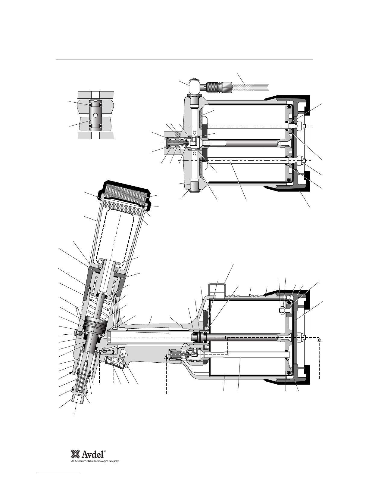
General Assembly of Base Too l 71 22 1- 02 00 0
B - B
A - A
6160
33
34
36
35
27
29
30
A
A
38
40
41
37
32
58
31
B
B
1 2 3 480 9 105 6 8
26
27
28
42
44
43
46
66
65
23
25
37
24
13
14
1516
63
11
127
A
62
22
45
18
19
21
20
767778
79
74
75
70
57
64
57
59
64
54
53
52
49-51
50
47
48
64
56
55
67
39
72
37 68 71 69
73
22

Parts List for 71221-02000
23
010203040506070809101112131415161819202122232425262728293031323334353637383940
41
71210-02101
07003-00277
71210-02103
71210-03320
71210-02104
07003-00333
71220-02121
07003-00273
07001-00405
07003-00194
07003-00341
07003-00342
71403-02110
07003-00278
71210-02029
71210-02022
07640-00239
71210-02051
07340-00335
07640-00244
71210-02028
71403-02120
07490-03002
71403-02104
71210-02019
07003-00288
71221-02013
07003-00287
71210-03800
71210-03205
71210-02014
71221-02027
71221-02001
07003-00182
71221-02002
07003-00274
71221-03210
71221-02004
71230-03600
71221-02008
JAW SPREADER HOUSING
'O' RING
LOCKNUT
HEAD ASSEMBLY
SEAL HOUSING
LIP SEAL
HEAD PISTON
LIP SEAL
SOCKET BUTTON HEAD SCREW
BONDED SEAL
LIP SEAL
'O' RING
BOTTLE ADAPTOR ASSEMBLY
'O' RING
SEAL
SUSPENSION RING
STEM COLLECTOR OUTER
STEM COLLECTOR BODY
STEM COLLECTOR END CAP
SILENCER
RETAINING NUT
END CAP ASSEMBLY
SPRING
SPRING CENTRALISING BUSH
SEAL RETAINER
'O' RING
HANDLE ASSEMBLY
'O' RING
INTENSIFIER SEAL ASSEMBLY
GUIDE RING
CLAMP NUT
LABEL
BODY - MACHINED
'O' RING
BASE COVER - MACHINED
LIP SEAL
PNEUMATIC PISTON ASSEMBLY (INCLUDES 31/35/37)
TIE ROD
TRANSFER TUBE ASSEMBLY
LINER - MACHINED
111111111112111111111111121111111114121
1
-
1
1
-
-1-
1121211-1
-
-1-
-1-
-
121
-
-1-
-1-1---
-
424344454647484950515253545556575859606162636465666768697071727374757677787980
81
07005-00088
71210-02008
71210-02024
07003-00311
71220-02102
07003-00127
07005-01274
71210-03400
07003-00268
71210-03402
71210-03401
07003-00042
07003-00271
71210-03700
07008-00010
71210-02031
71221-02003
71210-02009
71210-02013
07003-00189
71210-02034
71210-02035
07003-00281
07003-00204
07003-00310
07007-00224
07002-00108
07003-00027
71221-02005
71221-02006
71221-02007
07007-01993
71221-20104
07002-00098
71221-20105
71221-20101
71221-20102
71221-20103
07007-01503
07900-00818
TRIGGER VALVE
TRIGGER
TRIGGER PIN
'O' RING
VACUUM SLEEVE
'O' RING
1
/8" BSP PLUG
VALVE SPOOL ASSEMBLY (50 to 53)
• 'O' RING
• VALVE SPOOL
• VALVE BODY
• 'O' RING
'O' RING
ON/OFF VALVE ASSEMBLY
FLEXIBLE HOSE
SILENCER
TOP PLATE
VALVE SEAT
ROTARY VALVE
'O' RING
SILENCER CAP#
SILENCER#
'O' RING
'O' RING
'O' RING
SPIROL PIN
M6 NYLOK NUT
'O' RING
BASE PLATE
SEALING WASHER
RUBBER BOOT
CENTRE POLE MAGNET
M5 X 19 COUNTERSUNK SCREW
M5 NYLOK NUT
COUNTER
COUNTER MOULDING
SPECIAL M4 SCREW
MOULD RETAINING NUT
LABEL BOOK SYMBOL
TOOL INSTRUCTION MANUAL
111111111111111211121131122212111111221
1
-----1-
-2-
-
2
1
-
-2---2-
131
1
-------------
-
1
ITEM PART Nº DESCRIPTION QTY SPARES ITEM PART Nº DESCRIPTION QTY SPARES
712 2 1 -02 0 0 0 P A RTS L IST * These a r e m i n i m u m r e c o m m e n d e d l evels of sp a r e s b a s e d o n r e g u l a r s e rvicing
Englis h

Priming
Priming is ALWAYS necessary after the tool has been dismantled and prior to operating. It may also be necessary to restore the full
stroke after considerable use, when the stroke may be reduced and fasteners are not fully placed by one operation of the trigger.
The recommended oil for priming is Hyspin VG32 available in 0.5l (part number 07992-00002) or one gallon containers (part number
07992-00006). Please see safety data below.
First Aid
SKIN:
Wash thoroughly with soap and water as soon as possible. Casual contact requires no immediate attention. Short term contact requires no
immediate attention.
INGESTION:
Seek medical attention immediately. DO NOT induce vomiting.
EYES:
Irrigate immediately with water for several minutes. Although NOT a primary irritant, minor irritation may occur following contact.
Fire
Flash point 232°C. Not classified as flammable.
Suitable extinguishing media: CO
2
, dry powder, foam or water fog. DO NOT use water jets.
Environment
WASTE DISPOSAL: Through authorised contractor to a licensed site. May be incinerated. Used product may be sent for reclamation.
SPILLAGE: Prevent entry into drains, sewers and water courses. Soak up with absorbent material.
Handling
Wear eye protection, impervious gloves (e.g. of PVC) and a plastic apron. Use in well ventilated area.
Storage
No special precautions.
To enable you to follow the priming procedure opposite, you will need to obtain a priming kit:
PART Nº DESCRIPTION
PRIMING KIT : 07900-00688
07900-00351 3mm ALLEN KEY
07900-00698 STOP NUT
07900-00700 PRIMING PUMP
07900-00224 4mm ALLEN KEY
07900-00734 MAXLOK
®
STOP NUT
Oi l Deta i ls
Hy s pin V G 32 O i l Saf e t y Da t a
Pr i ming K it
24

Priming
25
I M P O R T A N T
DISCONNECT THE TOOL FROM THE AIR SUPPLY OR SWITCH OFF AT VALVE 55.
REMOVE NOSE ASSEMBLY OR SWIVEL HEAD COMPONENTS.
All operations should be carried out on a clean bench, with clean hands in a clean area.
Ensure that the new oil is perfectly clean and free from air bubbles.
Care MUST be taken at all times, to ensure that no foreign matter enters the tool, or serious damage may result.
• Remove bleed screw 9 and seal 10.
• Connect air supply to tool and switch ON/OFF valve 55 to ‘ON” position.
• Invert tool over suitable container and actuate trigger. Waste oil will be ejected through the bleed screw hole.
CARE SHALL BE TAKEN TO ENSURE THAT THE BLEED HOLE IS NOT DIRECTED TOWARDS THE OPERATOR OR OTHER
PERSONNEL.
• Screw stop nut 07900-00698 onto jaw spreader housing 1.
• Disconnect air supply to tool or switch ON/OFF valve 55 to ‘OFF” position.
• Fill the priming pump with oil.
• Screw priming pump 07900-00700 into the bleed screw hole with seal 10 in place.
• Actuate the priming pump by pressing down and releasing several times until resistance is felt.
• Remove the priming pump and the stop nut.
• Replace bleed screw 9 and seal 10.
• Connect air supply to tool and switch ON/OFF valve 55 to ‘ON” position.
• Check that the stroke of the tool meets the minimum specification of 26 millimetres. To check the stroke, measure the distance
between the front face of jaw spreader housing 1 and the front face of the head, BEFORE pressing the trigger and when the
trigger is fully actuated. The stroke is the difference between the two measurements. If it does not meet the minimum
specification, repeat the priming procedure.
Item numbers in bold refer to the general assembly drawing and parts list on pages 22-23.
Pr i ming P ro c e dure
Englis h

Fault Diagnosis
* Pages 13-15 if a swivel head is used instead of a nose assembly
† Page 15 if a swivel head is used instead of a nose assembly
Item numbers in bold refer to the general assembly drawing and parts list on pages 22-23.
More than one Air leak Tighten joints or replace components
operation of the Insufficient air pressure Adjust air pressure to within specification 5
trigger needed to Lack of lubrication Lubricate tool at air inlet point 7
place fastener Worn or broken jaws Fit new jaws 8-11*
Low oil level or air in oil Prime tool 24-25
Build up of dirt inside the nose assembly Service nose assembly 8†
Tool will not grip Worn or broken jaws Fit new jaws 8-11*
stem of fastener Build up of dirt inside the nose assembly Service nose assembly 8-11*
Loose jaw housing Tighten against locking ring 8-11*
Weak or broken spring in nose assembly Fit new spring 8-11*
Incorrect component in nose assembly Identify and replace 8-11*
Rotary valve incorrectly adjusted Read ‘Operating Procedure’ 7
Jaws will not release Build up of dirt inside the nose assembly Service nose assembly 8†
broken stem of Jaw housing, nose tip or nose casing
fastener not properly seated Tighten nose assembly 8
Weak or broken spring in nose assembly Fit new spring 8-11*
Air or oil leak Tighten joints or replace components
Low oil level or air present in oil Prime tool 24-25
Cannot feed next Broken stems jammed inside tool Empty stem collector 4 (point 14)
fastener Check jaw spreader is correct 8-11*
Adjust air pressure to within specification 5
Rotary valve incorrectly adjusted Adjust as in ‘Operating Procedure’ 7
Slow cycle Lack of lubrication Lubricate tool at air inlet point 8
Low air pressure Adjust air pressure to within specification 5
Build up of dirt inside the nose assembly Service nose assembly 9†
Tool fails to operate No air pressure Connect and adjust to within specification 5
Damaged trigger valve 42 Replace 19-20
Loose base cover 36 Tighten 19-20
Loose stem collector Tighten retaining nut 22 19-20
Fastener fails to break Insufficient air pressure Adjust air pressure to within specification 5
Fastener outside tool capability Use more powerful Genesis tool.
Contact Avdel UK Limited
Low oil level or air present in oil Prime tool 24-25
Other symptoms or failures should be reported to your local Avdel authorised distributor or repair centre.
Sy mpt om Po s si b le Ca u se R eme dy Pa ge Ref
26

27
Declaration of Conformity
We, Avdel UK Limited, Mundells, Welwyn Garden City, Herts, AL7 1EZ
declare under our sole responsibility that the product:
Model G3 HD
Serial No. ................................................
to which this declaration relates is in conformity with the following standards:
EN292 part 1 and part 2
ISO 8662 part 1 EN 60742/0695
ISO 3744 EN 50081-1
ISO PREN792 part 14 EN 55014
following the provisions of the Machine Directive 89/392/EC
(as amended by Directive 91/368/EC, 93/44/EC) and 93/68/EC
Welwyn Garden City - date of issue
A R Dear - Design & Development Manager
This box contains a power tool which is in
conformity with Machines Directive
89/392/EC. The ‘Declaration of Conformity’
is contained within.


29
Normas de seguridad 30
Especificaciones
Especificaciones de la máquina 31
Dimensiones de la máquina 31
Uso previsto
Gama de remaches 32
Números de pieza 32
Puesta en servicio
Suministro de aire 33
Procedimiento de funcionamiento 33
Boquillas
Instrucciones de montaje 34
Instrucciones de mantenimiento 34
Sufrideras 35-37
Accesorios
Deflector de vástagos 38
Extensión 38
Eyector lateral 38
Cabezales giratorios 39
Preparación de la máquina base 40
Instrucciones de montaje del cabezal giratorio 41
Instrucciones de mantenimiento del cabezal giratorio 42
Mantenimiento de la máquina
Diario / Semanal 43
Datos de seguridad de la grasa de Litio Moly EP 3753 43
Datos de seguridad de la grasa MolyKote 55m y MolyKote 111 44
Anual 45
Kit de mantenimiento 45
Conjunto de cabezal 45-46
Conjunto de émbolo neumático 46
Conjunto de manguito de válvula 46
Gatillo 46
Montaje general de la máquina base
Montaje general y lista de componentes 48-49
Cebado
Detalles del aceite 50
Datos de seguridad del aceite Hyspin VG 32 50
Juego para cebado 50
Procedimiento de cebado 51
Diagnóstico de averías
Síntoma, causa posible y solución 52
La política de Avdel Sistemas de Fijación es la de desarrollo y mejora continua del producto, reservándose el derecho de cambiar las especificaciones de cualquier producto sin previo aviso.
Garantía
Las máquinas de colocación de Avdel Sistemas de Fijación poseen una garantía de 12
meses frente a defectos originados por componentes defectuosos o por mano de obra,
iniciándose el período de garantía a partir de la fecha de entrega confirmada por la
factura o nota de envio.
La garantía es aplicable al usuario / comprador cuando la venta se realice a través de
un distribuidor autorizado, y únicamente con el propósito adecuado. La garantía
quedará invalidada si no se lleva a cabo el servicio, el mantenimiento y el
funcionamiento de la máquina de instalación de acuerdo a las instrucciones contenidas
en los Manuales de servicio e instrucciones.
En caso de fallo o defecto, queda a la elección de Avdel Sistemas de Fijación el llevar
a cabo la reparación o la sustitución de los componentes defectuosos.
Índice Españo l

30
Normas de seguridad
1 No la usen para otro propósito que no sea aquel para el que está diseñada.
2 No utilizar con esta máquina/herramienta ningún otro equipo más que el recomendado y suministrado por Avdel Sistemas de Fijación.
3 Cualquier modificación realizada por el cliente en la herramienta/máquina, las boquillas, accesorios o en cualquier equipo suministrado
por Avdel Sistemas de Fijación o por sus representantes, será de entera responsabilidad del cliente. Avdel Sistemas de Fijación
aconsejará gustosamente sobre cualquier modificación propuesta.
4 La herramienta/máquina debe mantenerse en condiciones seguras de trabajo en todo momento y debe ser examinada a intervalos
regulares en cuanto a funcionalidad y existencia de posibles daños por personal con formación adecuada. Cualquier operación de
desmontaje será únicamente llevada a cabo por personal con conocimiento en los procedimientos de Avdel Sistemas de Fijación. No
desmontar esta máquina/herramienta sin consultar previamente las instrucciones de mantenimiento. Sírvanse contactar con Avdel
Sistemas de Fijación haciendo mención a sus necesidades de formación.
5 La máquina/herramienta debe funcionar, en todo momento, de acuerdo con la legislación vigente en Seguridad y Salud. Cualquier
pregunta referente a la utilización correcta de la máquina y a la seguridad del operario, deberá estar dirigida a Avdel Sistemas de
Fijación.
6 Las precauciones que deben observarse cuando se use esta herramienta/máquina, deben ser explicadas por el cliente a todos los
operarios.
7 Antes de intentar ajustar, adaptar o retirar una boquilla, debe desconectarse siempre la línea de aire de la entrada de la
herramienta/máquina.
8 No hacer funcionar una herramienta/máquina que se encuentre dirigida hacia cualquier persona(s) o hacia el propio operario.
9 Adoptar siempre una posición de apoyo firme y estable antes de hacer funcionar la herramienta/máquina.
10 Asegurarse de que los orificios de escape no se encuentran bloqueados ni tapados.
11 La presión de trabajo no debe superar los 7 bar.
12 No accionar la máquina sin que la boquilla o el cabezal giratorio se encuentren montados en su totalidad, a menos que se indique
específicamente lo contrario.
13 Deben tomarse las precauciones debidas para asegurarse que los vástagos gastados no constituyan un peligro.
14 Si la máquina lleva incorporado un colector de vástagos, éste deberá vaciarse cuando se encuentre a la mitad de su capacidad.
15 Si la máquina G3 incorpora un deflector de vástagos, éste deberá girarse hasta que la abertura se encuentre en dirección opuesta a
la posición del operario y de cualquier otra persona(s) que trabaje(n) en las proximidades.
16 Cuando se utilice la máquina, se hace necesaria la utilización de gafas de seguridad, tanto por parte del operario como de cualquier
persona que se encuentre en las proximidades, a fin de protegerse de la proyección de cualquier remache, en el caso de que éste
saliera despedido al aire. Se recomienda la utilización de guantes en el caso de que la aplicación presente bordes o esquinas afilados.
17 Prestar especial atención para evitar posibles enredos de ropas, corbatas, cabellos, trapos, con las partes móviles de la máquina, las
cuales deberán mantenerse secas y limpias para favorecer en lo posible el agarre.
18 Cuando se transporte la máquina de un emplazamiento a otro, mantener las manos alejadas del gatillo para evitar que se produzca un
arranque inadvertido.
19 Deberá evitarse un contacto excesivo con aceite hidráulico. Para minimizar la posibilidad de erupciones cutáneas, deberá tomarse la
precaución de lavarse a fondo.
Este manual de instrucciones debe ser leído con una atención particular teniendo en cuenta las siguientes
reglas de seguridad, por cualquier persona que instale, haga funcionar o que repare esta máquina.
 Loading...